

Craftsman 143994016 Owner’s Manual
SEARS
operator's
manual
MODEL NO. 143.994016
4.0 RESERVE POWER
10 CUBIC INCH
(164cc)
DISPLACEMENT
l
SOLID STATE IGNITION
ENGIN
CAUTION:
Read RULES for
Safe OPERATION
and INSTRUCTIONS
Carefully
California Proposition 65 WARNING: The engine exhaust from this productcontains chemicals [
known to the State of California to cause cancer, birth defects or other reproductive harm.
Sold by SEARS, ROEBUCK AND CO., CHICAGO, IL 60684 U.S.A.
and SEARS CANADA, INC., TORONTO, ONTARIO, CANADA
Printed in U.S.A. 4-1-99 181-1188-11
• Operating
• Maintenance
• Repair Parts
I
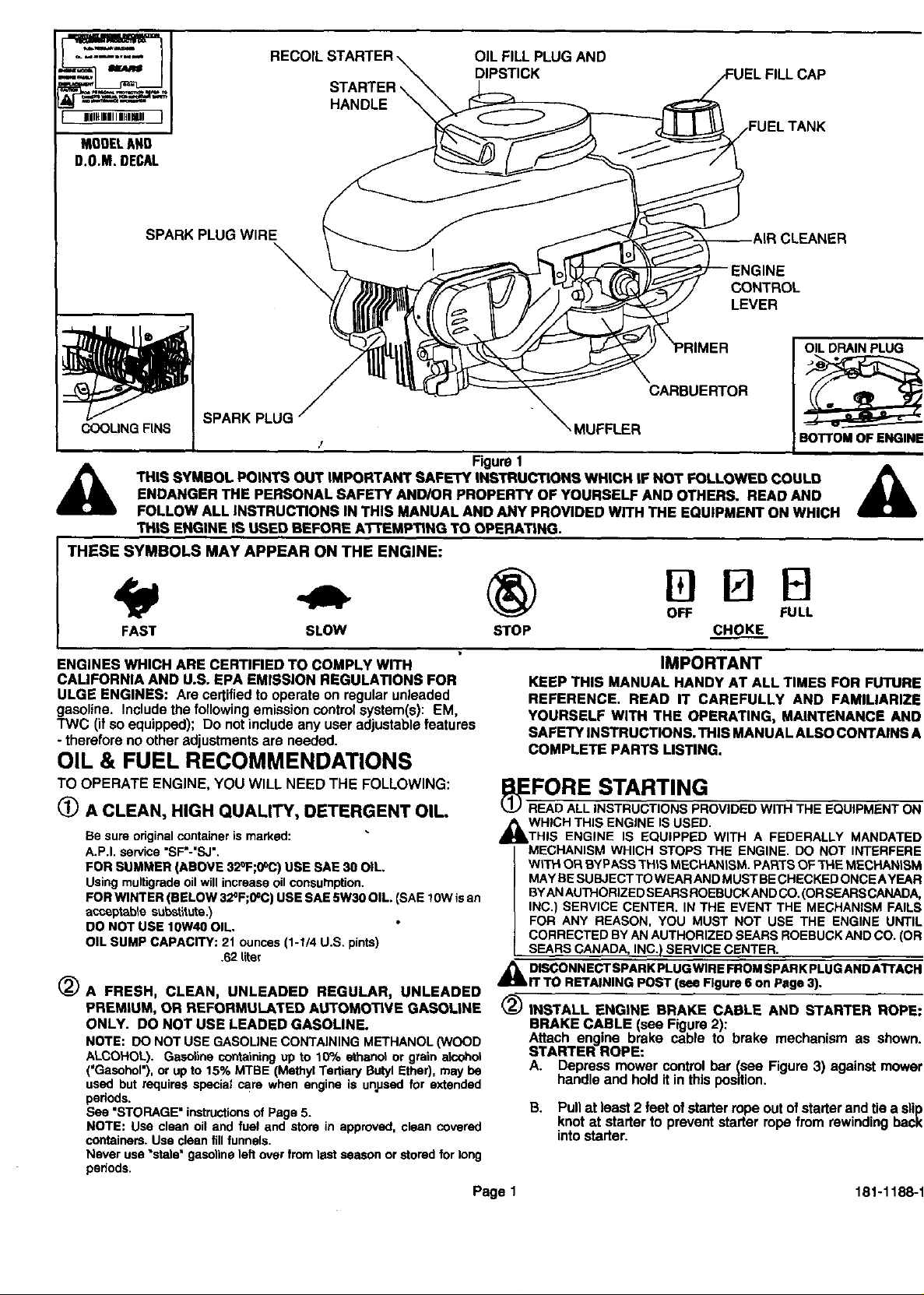
STARTER,
HANDLE
MODELANO
D.O.M.DECAL
SPARK PLUG WIRE CLEANER
SPARK PLUG
/
THIS SYMBOL POINTS OUT IMPORTANT SAFETY INSTRUCTIONS WHICH IF NOT FOLLOWED COULD ._
ENDANGER THE PERSONAL SAFETY AND/OR PROPERTY OF YOURSELF AND OTHERS. READ AND
FOLLOW ALL INSTRUCTIONS IN THIS MANUAL ANDANY PROVIDED WITH THE EQUIPMENT ON WHICH
THIS ENGINE IS USED BEFORE A3"rEMFnNG TO OPERATING.
THESE SYMBOLS MAY APPEAR ON THE ENGINE:
OIL FILL PLUG AND
DIPSTICK
,MUFFLER
Figure1
CONTROL
LEVER
OIL DRAIN PLUG
CARBUERTOR
BOTTOM OF ENGINE
Alt
FAST SLOW STOP CHOKE
ENGINES WHICH ARE CERTIFIED TO COMPLY WITH
CALIFORNIA AND U.S. EPA EMISSION REGULATIONS FOR
ULGE ENGINES: Are certified to operate on regular unleaded
gasoline, Include the following emission control system(s): EM,
TWC (if so equipped); Do not include any user adjustable features
- therefore no other adjustments are needed.
OIL & FUEL RECOMMENDATIONS
TO OPERATE ENGINE, YOU WILL NEED THE FOLLOWING:
_) A CLEAN, HIGH QUALITY, DETERGENT OIL
Be sure original container is marked:
A.P.I. service "SF'-"SJ'.
FOR BUMMER (ABOVE 32°F;0°C) USE SAE 30 OIL.
Using multigrede oil will increase oil consumption.
FOR WINTER (BELOW 32°F;0°C) USE SAE 5W30 OIL. (SAE 10W is an
accoptable substilute.)
DO NOT USE 10W40 OIL.
OIL SUMP CAPACITY: 2t ounces (1-1/4 U.S. pints)
.62 liter
(_A FRESH, CLEAN, UNLEADED REGULAR, UNLEADED
PREMIUM, OR REFORMULATED AUTOMOTIVE GASOLINE
ONLY. DO NOT USE LEADED GASOLINE.
NOTE: DO NOT USE GASOLINE CONTAINING METHANOL (WOOD
ALCOHOL). Gasetine containing up to 10°/= sthanot or grain ateehol
('Gasohol'), or up to 15% MTBE (Methyl Tertiary Butyl Ether), may be
used but requires special care when engine is unused for extended
periods.
See "STORAGE" instructions of Page 5.
NOTE: Use clean oil and fuel and store in approved, clean covered
containers. Use clean fill funnels.
Never use "stale" gasoline left over from last season or stored for long
periods.
OFF FULL
IMPORTANT
KEEP THIS MANUAL HANDY AT ALL TIMES FOR FUTURE
REFERENCE. READ IT CAREFULLY AND FAMILIARIZE
YOURSELF WITH THE OPERATING, MAINTENANCE ANO
SAFETY INSTRUCTIONS. THIS MANUAL ALSO CONTAINS A
COMPLETE PARTS LISTING.
ERFORE STARTING
EAD ALL INSTRUCTIONS PROVIDED WITH THE EQUIPMENT ON
_b WHICH THIS ENGINE IS USED.
THIS ENGINE IS EQUIPPED WITH A FEDERALLY MANDATED
MECHANISM WHICH STOPS THE ENGINE. DO NOT INTERFERE
WiTH OR BYPASS THiS MECHANISM. PARTS OF TPIE MECHANISM
MAY BE SUBJECTTO WEAR AND MUST BE CHECKED ONCEAYEAR
BYAN AUTHORIZED SEARS ROEBUCKAND CO. (OR SEARS CANADA,
INC.) SERVICE CENTER. IN THE EVENT THE MECHANISM FAILS
FOR ANY REASON, YOU MUST NOT USE THE ENGINE UNTIL
CORRECTED BY AN AUTHORIZED SEARS ROEBUCK AND CO. (OR
SEARS CANADA, INC.) SERVICE CENTER.
_ DISCONNECT SPARK PLUG WIRE FROM SPARK PLUG AND ATTACH
IT TO RETAINING POST (see Figure 6 on Page 3).
(_ INSTALL ENGINE BRAKE CABLE AND STARTER ROPE:
BRAKE CABLE (see Figure 2):
Attach engine brake cable to brake mechanism as shown.
STARTER ROPE:
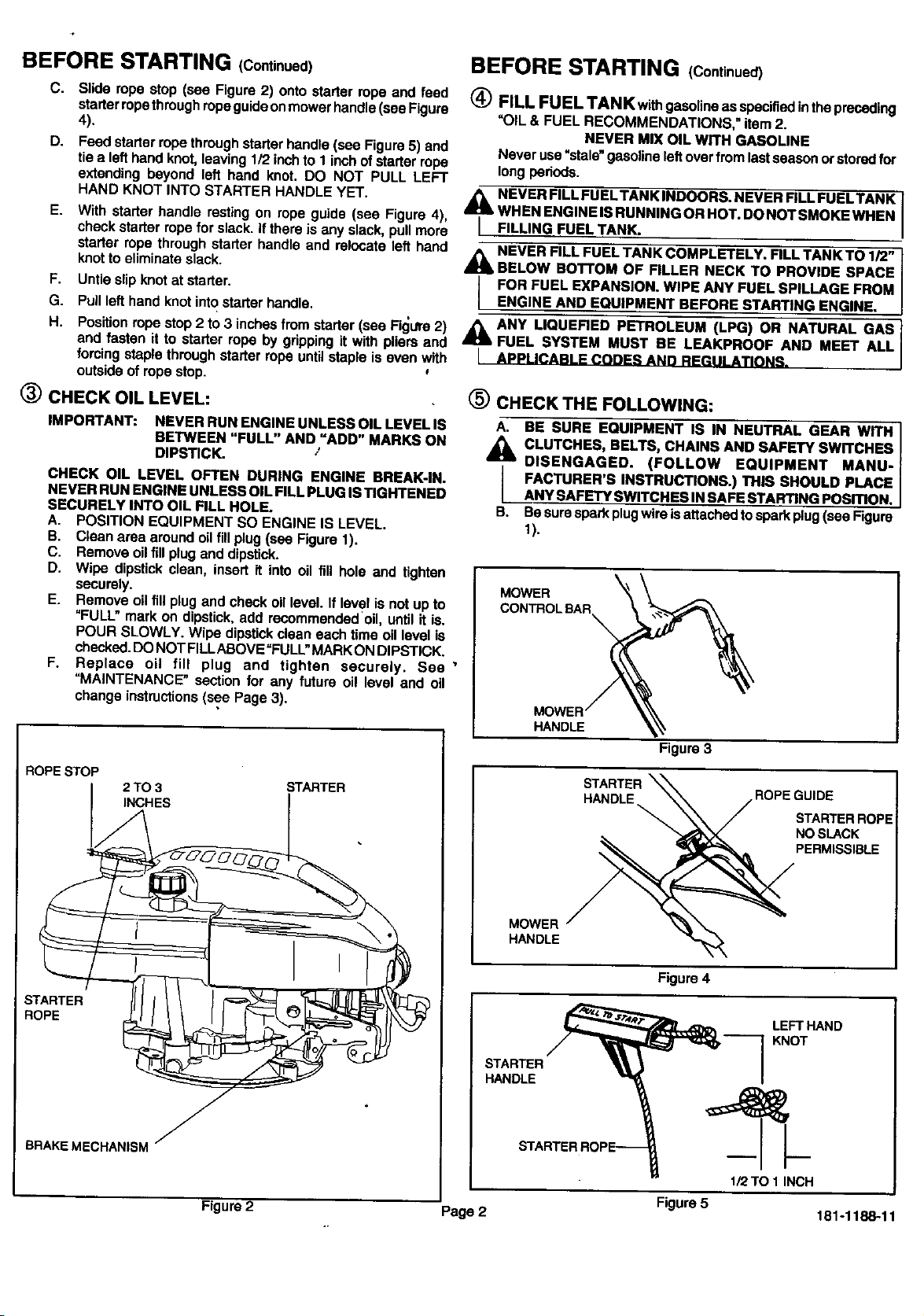
A. Depress mower control bar (see Figure 3) against mower
handle and hold it in this posdion.
B. Pullat least2 feet ofstarterropeout ofstarterandtie a slip
knotat starterto preventstarter ropefrom rewinding back
intostarter.
Page 1 181-1188-1
BEFORE STARTING (Continued)
C. Slide ropestop (see Figure2) onto starter ropeand feed
starer ropethroughropeguideonmowerhandle(seeFigure
4).
D. Feedstarterropethroughstarterhandle(see Figure5) and
tiea lefthandknot,leaving1/2 inchto 1 inchofstarer rope
extendingbeyond left hand knot. DO NOT PULL LEFT
HAND KNOT INTO STARTER HANDLEYET.
E. With starer handle resting on rope guide (see Figure 4),
checkstarterrope for slack.If there is any slack,pull more
starer rope through starer handle and relocate left hand _ NEVER FILL FUEL TANK COMPLETELY. FILL TANK TO 1/2"
knot to eliminate slack. _ BELOW BO'I'FOM OF FILLER NECK TO PROVIDE SPACE
F. Untie slip knot at starter. _ FOR FUEL EXPANSION. WIPE ANY FUEL SPILLAGE FROM
G. Pull left hand knot into starter handle, [ ENGINE AND EQUIPMENT BEFORE STARTING ENGINE.
H. Position rope stop 2 to 3 inches from starter (see Fig.s 2) &,_ ANY LIQUERED PETROLEUM (LPG) OR NATURAL GAS
and fasten it to starter rope by gripping it with pliers and a FUEL SYSTEM MUST BE LEAKPROOF AND MEET ALL
forcing staple through starter rope until staple is even with I APPLICABLE CODES AND REGULATIONS.
outside of rope stop.
BEFORE STARTING (Continued)
(_ FILL FUEL TANK withgasoline as specified inthe preceding
"OIL & FUEL RECOMMENDATIONS," item 2.
NEVER MIX OIL WITH GASOLINE
Never use "stale" gasoline leftover from last season or stored for
long periods.
_lb NEVER FILL FUEL TANK INDOORS. NEVER FILL FUELTANK
WHEN ENGINE IS RUNNING OR HOT. DO NOT SMOKE WHEN
FILLING FUEL TANK.
(_) CHECK OIL LEVEL: (_ CHECK THE FOLLOWING:
IMPORTANT: NEVER RUN ENGINE UNLESS OIL LEVELIS
BETWEEN "FULL" AND =ADD" MARKS ON
DIPSTICK.
CHECK OIL LEVEL OFTEN DURING ENGINE BREAK-IN.
NEVER RUN ENGINE UNLESS OIL FILL PLUG IS TIGHTENED
SECURELY INTO OIL FILL HOLE.
A. POSITION EQUIPMENT SO ENGINE IS LEVEL.
S. C|esn area around o_1fill plug (see F_Jure 1).
C. Remove oil fill plug and dipstick.
D. Wipe dipstick clean, insert it into oil fill hole and tighten
securely.
E. Remove oil fill plug and check oil level. If level is not up to
"FULL" mark on dipstick, add recommendedoil, until it is.
POUR SLOWLY. Wipe dipstick clean each time oil level is
checked. DO NOT FILLABOVE =FULL" MARK ON DIPSTICK.
F. Replace oil fill plug and tighten securely. See'
"MAINTENANCE" section for any future oil level and oil
change instructions (see Page 3),
A. BE SURE EQUIPMENT IS IN NEUTRAL GEAR WITH I
CLUTCHES, BELTS, CHAINS AND SAFETY SWITCHES I
DISENGAGED. (FOLLOW EQUIPMENT MANU- I
FACTURER'S INSTRUCTIONS.) THIS SHOULD PLACE
ANY SAFETY SWITCHES IN SAFE STARTING POSITION.
B. Be sure spark plugwire isattached to spark plug (see Figure
1).
MOWER
HANDLE
Figure 3
ROPESTOP
2TO 3 STARTER
INCHES _ .
ROPE
STARTER
BRAKEMECHANISM
I -7
Figure 2
Page2
STARTER
HANDLE ROPE GUIDE
STARTER ROPE
NO SLACK
PERMISSIBLE
MOWER
HANDLE
Figure 4
LEFT HAND
KNOT
STARTER
HANDLE
1/2TO 1 INCH
Figure 5 181-1188-11
STARTING
_ NEVER RUN ENGINE INDOORS OR IN ENCLOSED, POORLY
VENTILATED AREAS. ENGINE EXHAUST CONTAINS
CARBON MONOXIDE, AN ODORLESS AND DEADLY GAS
(CARBON MONOXIDE IS ALSO PRESENT IN ENGINE
EXHAUST FROM LIQUID PETROLEUM (LPG) AND NATURAL
GAS FUEL SYSTEMS).
KEEP HANDS, FEET, HAIR AND LOOSE CLOTHING AWAY
_FROM ANY MOVING PARTS ON ENGINE AND EQUIPMENT.
MAINTENANCE
_ WARNING TEMPERATURE OF MUFFLER AND NEARBY
AREAS MAY EXCEED 15(]PF (65°C). AVOID THESE AREAS.
CHECK OIL LEVEL:
Checkoilleveleveryfive(5) operatinghoursoreachtimeengine
isused.See "3CHECK OILLEVEL"in=BEFORESTARTING"on
Page2.
_L WARNING TEMPERATURE OF MUFFLER AND NEARBY
AREAS MAY EXCEED 150°F (65°C). AVOID THESE AREAS.
Move engine control (see Figure 1) to HI Position.
+
(_ START ENGINE:
A.
Thecarburetoronyourenginehasbeencompletelyal:ljusted
at thefactory. Whenstartinga cold engine,pushredprimer
bulbfirmly with your thumb 5 times, allowingprimerbulb
to returncompletely to originalpositionbetweenpushes.
Repeat theabovefor eachstarteroperationas necessary.
NOTE: DO NOT USE PRIMER TO RESTART A WARM
ENGINE AFTER A SHORT SHUTDOWN,
B. Operatemowercontroltoreleaseengine brake.
C. Graspstarterhandle(seeFigure4) andpullropeout,slowly,
untilitpullsslightlyharder.Letroperewindslowly.Thenpull
ropewitha rapidfull arm stroke.Let rope rewindSLOWLY.
Do notletstarterhandlesnapbackagainstropeguide(see
Figure4).
D+ RepeatinstructionsBandC ifnecessary,untilenginestarts.
NOTE: if enginedoesnotstart,repeatinstructionsA, B, C
and D untilitstarts.
ENGINE SPEED: Enginespeed iscontrolledbythe enginecontrol
(see Figure1). Enginecontrolshouldbe inHI positionfor highgrass
conditionsandfor mostefficientbagginginheavy grassconditions,
and in LOW positionfor lightgrass,trimmingandfor fuel economy.
STOPPING
(_) See mower manufacturer's instructions.
(_ AFTER ENGINE IS STOPPED:
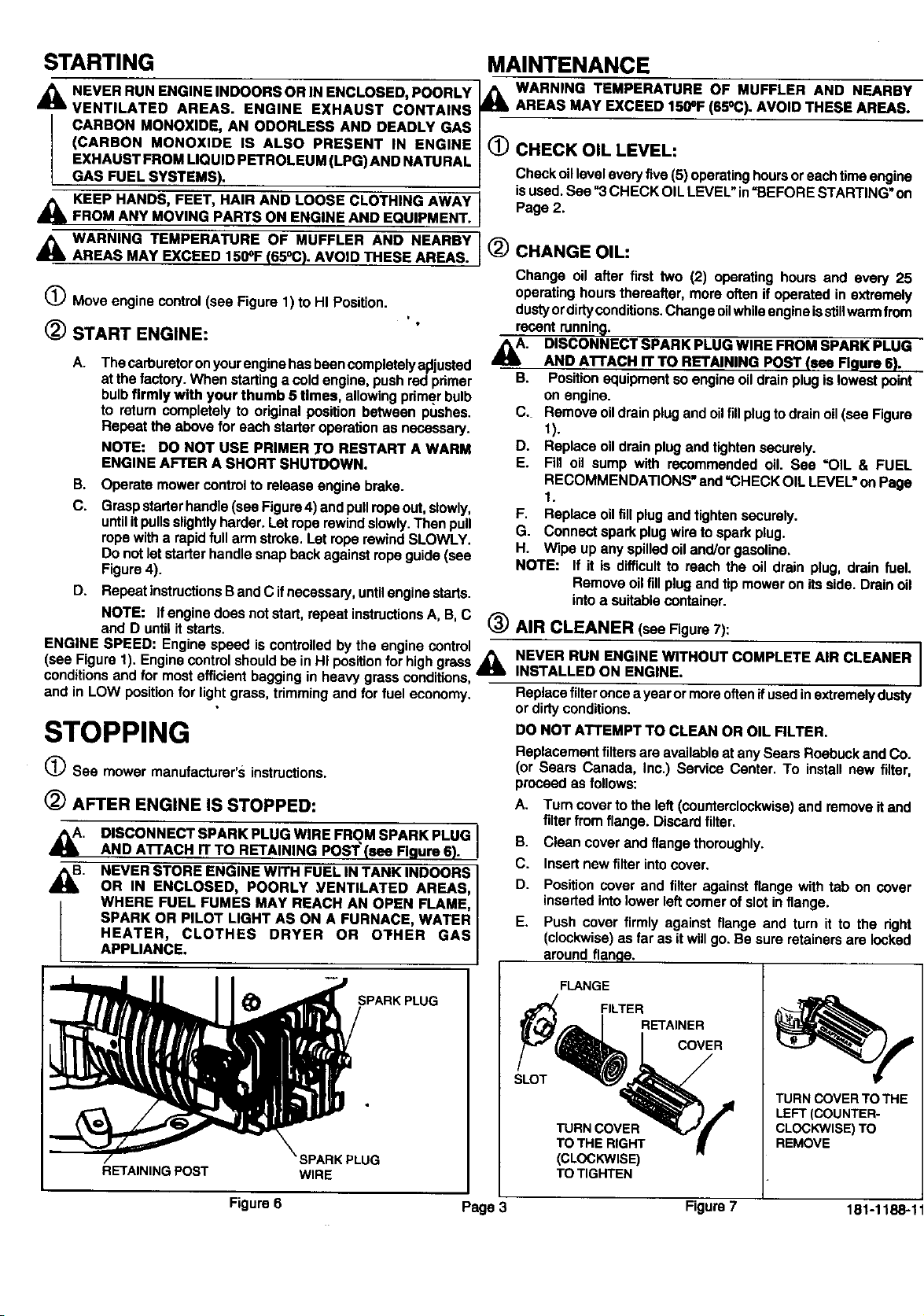
_. DISCONNECT SPARK PLUG WIRE FROM SPARK PLUG
_. NEVER STORE ENGINE WITH FUEL IN TANK INDOORS
AND ATrACH IT TO RETAINING POST (see Figure 6).
OR IN ENCLOSED, POORLY ,VENTILATED AREAS,
WHERE FUEL FUMES MAY REACH AN OPEN FLAME,
SPARK OR PILOT LIGHT AS ON A FURNACE, WATER
HEATER, CLOTHES DRYER OR OTHER GAS
APPLIANCE.
_) CHANGE OIL:
Change oil after first two (2) operating hours and every 25
operating hours thereafter, more often if operated in extremely
dusty or dirtyconditions. Change oilwhile engine isstill warm from
recent running.
_. DISCONNECT SPARK PLUG WIRE FROM SPARK PLUG
AND ATrACH IT TO RETAINING POST (see Figure 6). I
B. Position equipment so engine oil drain plug is lowest point
on engine.
C. Remove oil drain plug and oil fill plug to drain oil (see Figure
1).
D. Replace oil drain plug and tighten securely.
E. Fill oil sump with recommended oil. See "OIL & FUEL
RECOMMENDATIONS" and "CHECK OIL LEVEL" on Page
1.
F. Replace oil fill plug and tighten securely.
G. Connect spark plug wire to spark plug.
H. Wipe up any spilled oil and/or gasoline.
NOTE: If it is difficult to reach the oil drain plug, drain fuel.
Remove oil fill plug and tip mower on its side. Drain oil
into a suitable container.
_) AIR CLEANER (seeFigure7):
_ NEVER RUN ENGINE WITHOUT COMPLETE AIR CLEANER
INSTALLED ON ENGINE.
Replace filter once a year or more often ifused in extremely dusty
or dirty conditions.
DO NOT ATTEMPT TO CLEAN OR OIL FILTER,
Replacement filtersare available at any Sears Roebuck and Co.
(or Sears Canada, Inc.) Service Center. To install new filter,
proceed as follows:
A. Turn cover to the left (counterclockwise) and remove itand
filter from flange. Discard filter.
B. Clean cover and flange thoroughly.
C. Insert new filter into cover.
D. Position cover and filter against flange with tab on cover
inserted into lower left comer of slot in flange.
E. Push cover firmly against flange and turn it to the right
(clockwise) as far as it will go. Be sure retainers are locked
around flange.
I
RETAINING POST
FLANGE
SPARKPLUG
SLOT
WIRE
Figure 6 Page 3 Figure 7 181-1188-11
FILTER
TURN COVER
TO THE RIGHT
(CLOCKWISE)
TO TIGHTEN
RETAINER
COVER
TURN COVER TOTHE
LEFT(COUNTER-
CLOCKWISE)TO
REMOVE
 Loading...