

Craftsman 139.53960SRT, 139.53968SRT, 139.53971SRT, 139.53970SRT, 139.53973SRT Owner's Manual
Owner's Manual/Manual Del Propietario
112 HP
GARAGE DOOR OPENER
ABRIDOR DE PUERTA DE COCHERA
For Residential Use Only/S61o para uso residencial
Model/Modelos 139.53960SRT • 139.53968SRT • 139.53970SRT
139.53971SRT • 139.53973SRT
m
f.n
.-r-
Zt
CAUTION:
Read and follow all safety rules
and operating instructions before
first use of this product.
PRECAUCION:
Leer y seguir todas las reglas de
seguridad y las instrucciones de
operaci6n antes de usar este
producto por primera vez.
Fasten the manual near the garage
door after installation.
Guardar este manual cerca de la
puerta del garaje.
Comphes w=thUL 325 C_
regul_ons er{Bcbve
January _ 19_3 US
Cump_e con las
Regl_menta_ones UL 325
en vlgenc_a (lesde el 1 (_e
enero d6 1993
Sears, Roebuck and Co., Hoffman Estates, IL 60179 U.S.A
www.sears corn/craftsman
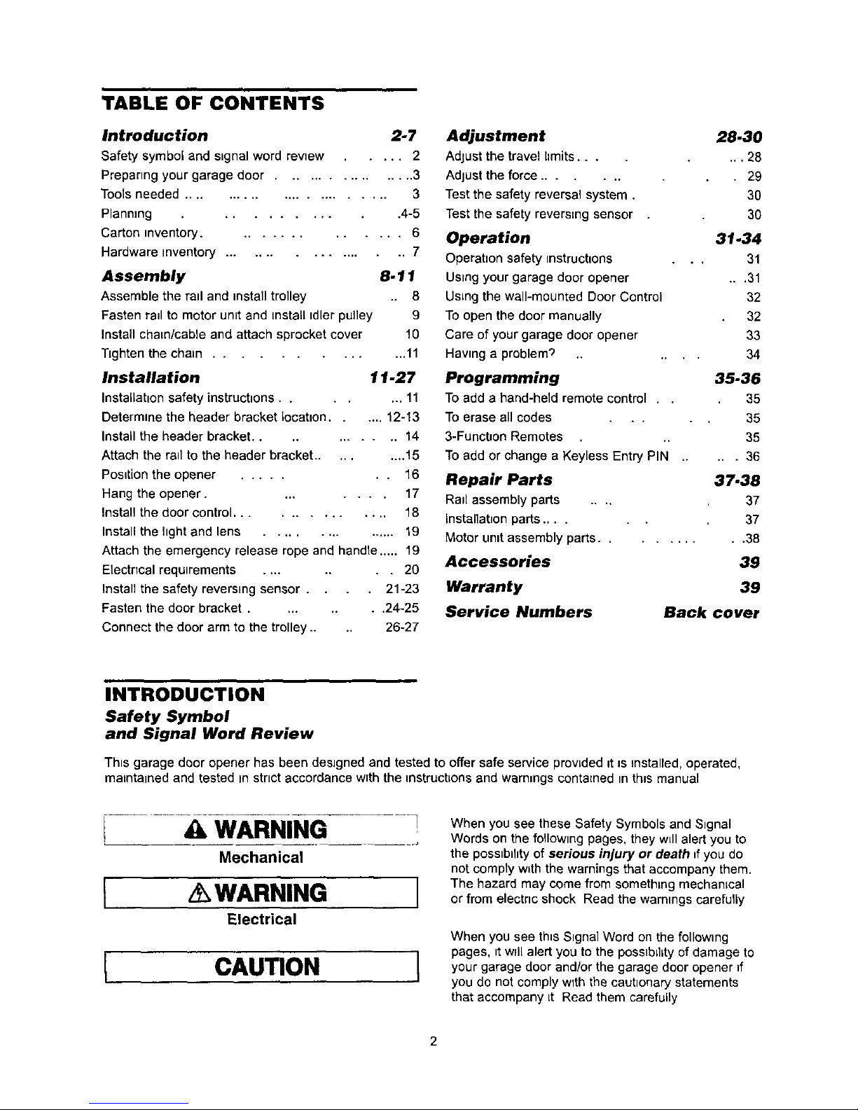
TABLE OF CONTENTS
Introduction 2-7
Safety symbol and signal word review ..... 2
Preparing your garage door ................. 3
Tools needed ........................ 3
Planning .......... 4-5
Carton inventory .............. 6
Hardware inventory ................ 7
Assembly 8.11
Assemble the rail and installtrolley 8
Fasten rail to motor unit and installidler pulley 9
Install chain/cable and attach sprocket cover 10
Tighten the chain ............. 11
Installation 11-27
Installation safety instructions ....... 11
Determine the header bracket location ..... 12-13
Install the header bracket ......... 14
Attach the rail to the header bracket ......... 15
Position the opener ....... 16
Hang the opener ........ 17
Install the door control .............. 18
Install the light and lens ............... 19
Attach the emergency release rope and handle ..... 19
Electncal requirements ...... 20
Instalt the safety reversing sensor . 21-23
Fasten the door bracket ...... 24-25
Connect the door arm to the trolley .... 26-27
Adjustment
Adjust the travel limits...
Adjust the force .......
Test the safety reversal system.
Test the safety reversing sensor
Operation
Operatton safety instructions
Ustng your garage door opener
Using the wall-mounted Door Control
To open the door manually
Care of your garage door opener
Having a problem'_
Programming
To add a hand-held remote control .
To erase all codes . .
3-Function Remotes
To add or change a Keyless Entry PIN
Repair Parts
Rail assembly parts ....
Installation parts ....
Motor unit assembly parts..
Accessories
Warranty
Service Numbers
28.30
... 26
• 29
30
30
31.34
.. 31
...31
32
32
33
34
35-36
35
35
35
... 36
37.38
37
37
...... 38
39
39
Back cover
INTRODUCTION
Safety Symbol
and Signal Word Review
This garage door opener has been designed and tested to offer safe service prowded it _sinstalled, operated,
maintained and tested in strict accordance with the instructions and warnings contained in this manual
! 4tI WARNING
Mechanical
[ AWARNING l
Electrical
[ CAUTION l
When you see these Safety Symbols and Stgnal
Words on the following pages, they will alert you to
the possiblhty of serious injury or death ff you do
not comply whththe warnings that accompany them.
The hazard may come from something mechanical
or from electnc shock Read the warnings carefully
When you see th_sSignal Word on the following
pages, _tw_llalert you to the posstbdlty of damage to
your garage door and/or the garage door opener ff
you do not comply wTth the cautionary statements
that accompany [t Read them carefully
2
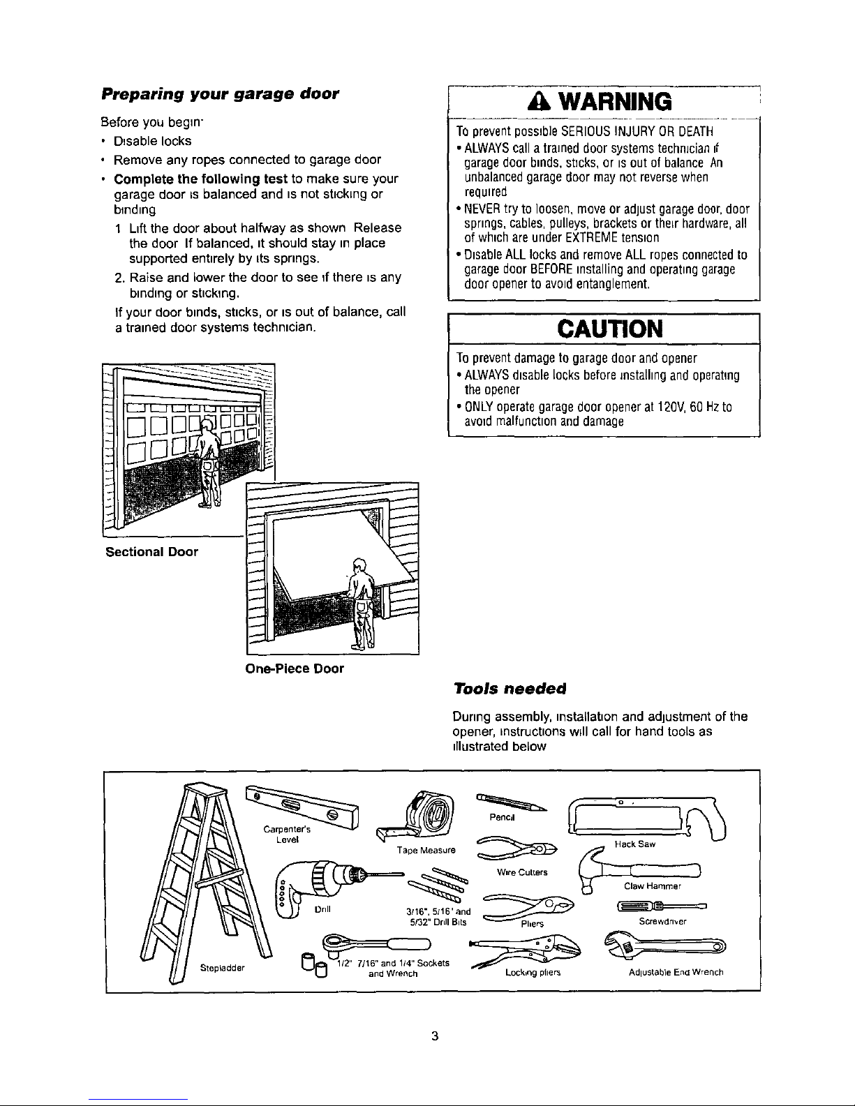
Preparing your garage door
Before you begin"
• Disable locks
• Remove any ropes connected to garage door
• Complete the following test to make sure your
garage door _sbalanced and _snot sbckmg or
binding
1 Lift the door about halfway as shown Release
the door If balanced, it should stay in place
supported entirely by its springs.
2. Raise and lower the door to see If there is any
binding or sticking.
If your door binds, sticks, or is out of balance, call
a trained door systems techmcian.
WARNING
Topreventposs_b]eSERIOUSINJURY013DEATH
• ALWAYScallatraJneddoor systemsteohmcian_f
garagedoorbrads,st_cks,or is outof balance An
unbalancedgaragedoor may not reversewhen
required
• NEVERtry to loosen,move or adjust garagedoer,door
spnngs,cables pulleys, bracketsor theLrhardware,all
of whichare underEXTREMEtension
• DisableALL locks and removeALL ropesconnectedto
garagedoor BEFOREinstallingand operatinggarage
door openerto avoidentanglement
CAUTION
Topreventdamageto garagedoor andopener
• ALWAYSd_sablelocks beforeJnstalhngand operating
theopener
• ONLYoperategaragedoor openerat 120V,60Hzto
avoidmalfunctionanddamage
Sectional Door
One-Piece Door
Level
Tools needed
During assembly,mstallabon and adjustment of the
opener, instructions w_llcall for hand tools as
dlustratedbelow
Stepladder
Drill
Pencil
Tape Measure
Wire CutLers
3/16", 5/16'and _--_
5!32" DrLIIBits PherS
Hack Saw
Screwdriver
AdluStable Encl Wrench
Planning
Identify the type and height of your garage door.
Survey your garage area to see if any of the
conditions below apply to your installation. Additional
materials may be required. You may find it helpful to
refer back to this page and the accompanying
illustrations as you proceed with the installation of
your opener.
Depending on your requirements, there are several
installation steps which may call for materials or
hardware not included in the carton.
• Installation Step 1 - Look at the wall or ceiling
above the garage door. The header bracket must
be securely fastened to structural supports.
• Installation Step 5 - Do you have a finished ceiling
in your garage? If so, a support bracket and
additional fastening hardware may be required.
• Installation Step 10 - Depending upon garage
construction, extension brackets or wood blocks
may be needed to install sensors.
• Installation Step 10-Alternate floor mounting of
the safety reversing sensor will require hardware
not provided.
Do you have an access door in addition to the
garage door? If not, Model 53702 Emergency Key
Release is required. See Accessories page.
Look at the garage door where it meets the floor.
Any gap between the floor and the bottom of the
door must not exceed 1/4". Otherwise, the safety
reversal system may not work properly. See
Adjustment Step 3. Floor or door should be
repaired.
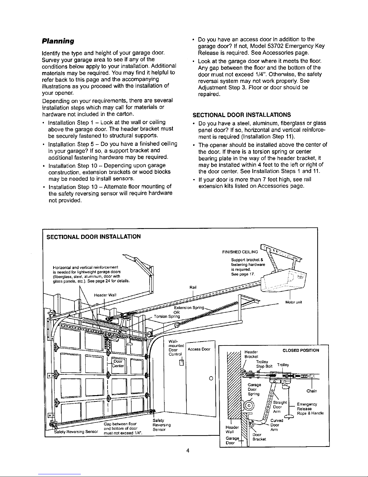
SECTIONAL DOOR INSTALLATIONS
• Do you have a steel, aluminum, fiberglass or glass
panel door? If so, horizontal and vertical reinforce-
ment is required (Installation Step 11).
• The opener should be installed above the center of
the door. If there is a torsion spring or center
bearing plate in the way of the header bracket, it
may be installed within 4 feet to the left or right of
the door center. See Installation Steps 1 and 11.
• If your door is more than 7 feet high, see rail
extension kits listed on Accessories page.
SECTIONAL DOOR INSTALLATION
FINISHED CEILING
Horizontal and vertical reinforcement
(fiberglass, steel, aluminum, door with
Header Wall
Rail
isrequited.
See page 17.
Motor unit
Header CLOSED POSITION
Bracket
Trolley
Stop Bolt Trolley
Chain
3ap between floor
and bottom of door
must not exceed 1/4".
Safety
Reversing
Sensor
Door
Arm
Door
Bracket
Emergency
Release
Rope & Handle
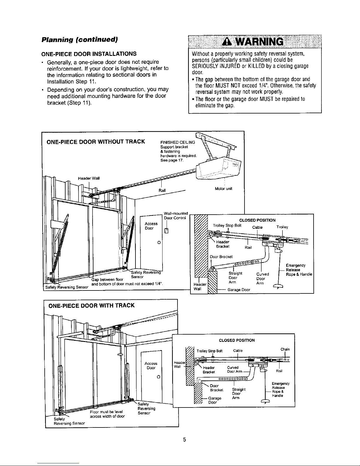
Planning (continued)
ONE-PIECE DOOR INSTALLATIONS
• Generally, a one-piece door does not require
reinforcement. If your door is lightweight,refer to
the information relating to sectional doors in
Installation Step 11.
• Depending on your door's construction, you may
need additional mounting hardware for the door
bracket (Step 11).
Withouta properlyworkingsafetyreversalsystem,
persons(particularlysmall children) could be
SERIOUSLYINJUREDor KILLEDbya closing garage
door
• Thegapbetweenthe bottomofthegaragedoorand
thefloor MUSTNOTexceed1/4". Otherwise,thesafety
reversalsystem may not work properly.
• Theflooror thegaragedoor MUSTberepairedto
eliminatethe gap.
ONE-PIECE DOOR WITHOUT TRACK
Header Wall
FINISHED CEILING
Support bracket
& fastening
hardware is required.
See page 17
Rail
Motor unit
Safety Reversing Sensor
Wall-mounted
Door Control
Access I /
Door ['t]
ol
Sensor
Gap between floor
and bottom of door must not exceed 1/4".
CLOSED POSITION
Trolley Stop Bolt Cable Trolley
I
Bracket
Door Bracket
Rail
Cu_ed
Door Door
Arm Arm
}eader
Vail Garage Door
Emergency
- Release
Rope & Handle
ONE-PIECE DOOR WITH TRACK
Floor must be level
ss width of door
Safety
Reversing Sensor
Access I
Door I
Ol
feb
Reversing
Sensor
CLOSED POSITION
Trolley Stop Bolt Cable Chain
Curved
Bracket Rail
Emergency
Bracket Straight Release
Door Handle
Arm
Door
5
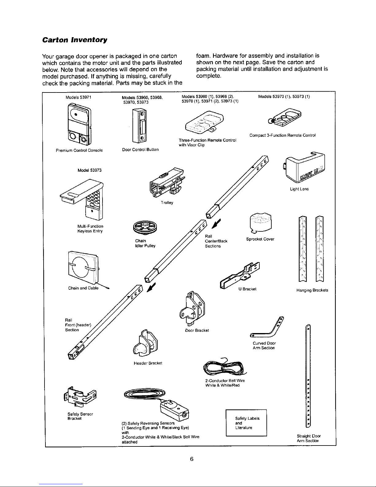
Carton Inventory
Your garage door opener is packaged in one carton
which contains the motor unit and the parts illustrated
below. Note that accessories will depend on the
model purchased. If anything is missing, carefully
check the packing material. Parts may be stuck in the
foam. Hardware for assembly and installation is
shown on the next page. Save the carton and
packing material until installation and adjustment is
complete.
Models 53971 Models 53960, 53968,
Premium Control Console Door Control Button
Model 53973
Multi-Function
Keyless Entry
Rail
Front (header)
Section
Safety Sensor
Bracket
Trolley
Models 53960 (1), 53968 (2),
53970 (1)1 53971 (2), 53973 (1)
Three-Function Remote Control
with Visor Clip
Chain
Idler Pulley
/
Rail
Center/Back
Sections
Models 53970 (1), 53973 (1)
Compact 3-Function Remote Control
Light Lens
©
Sprocket Cover
Door Bracket
Header Bracket
(2) Safety Reversin9 Sensors
(1 Sending Eye and 1 Receiving Eye)
with
2-Conductor White & White/Black Bell Wire
attached
J
Curved Door
Arm Section
2-Conductor Bell Wire
White & White/Red
Safety Labels
and
Literature
Hanging Brackets
Straight Door
Arm Section
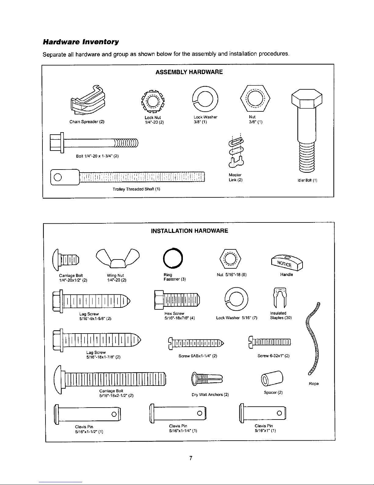
Hardware Inventory
Separate all hardware and group as shown below for the assembly and installation procedures.
ASSEMBLY HARDWARE
Lock Nut Lock Washer Nut
Chain Spreader (2) 1/4"-20 (2) 3/8" (1) 3/8" (1)
i
i
)//))//)///) _,
Bolt 1/4"-20 x 1-3/4" (2)
:,Ji,li,lli,i :i I¸¸ il,, ,;, ;i, ¸ , ,
!_l, !,,!dii,,,,,_,i:li,,,i:il, i:,i,, i!,ii,,i,,li, i,i,';',illl, l,i,;_,li,_l',_,ii, I
Trolley Threaded Shaft (1)
Master
Link (2)
Idler Bolt(1)
INSTALLATION HARDWARE
0 ©
Carriage Bolt Wing Nut Ring Nut 5116"-18 (8)
1/4"-20xl/2" (2) 1/4"-20 (2) Fastener (3)
_llLIlll_lllllllllll_
Lag Screw
5/16"-9xl-5/8" (2)
Hex Screw
5/16"-18x7/8" (4)
©
Lock Washer 5/16" (7)
IllllllLIIIIl!lL_llll[_
Lag Screw
5116"-18xl-7/8" (2)
(_ Carriage Bolt
i!lLIIllLillllllllLlilllllllll[!lll_
5116"-18x2-1/2" (2)
Dry Wall Anchors (2)
oll
Clevis Pin Clevis Pin
5116"x1-112"(1) 5/16"x1-114_(1)
Handle
Insulated
Staples (30)
Screw 6-32x1" (2)
Spacer (2)
o_
Clevis Pin
5/18"x1" (1)
i
J
Rope
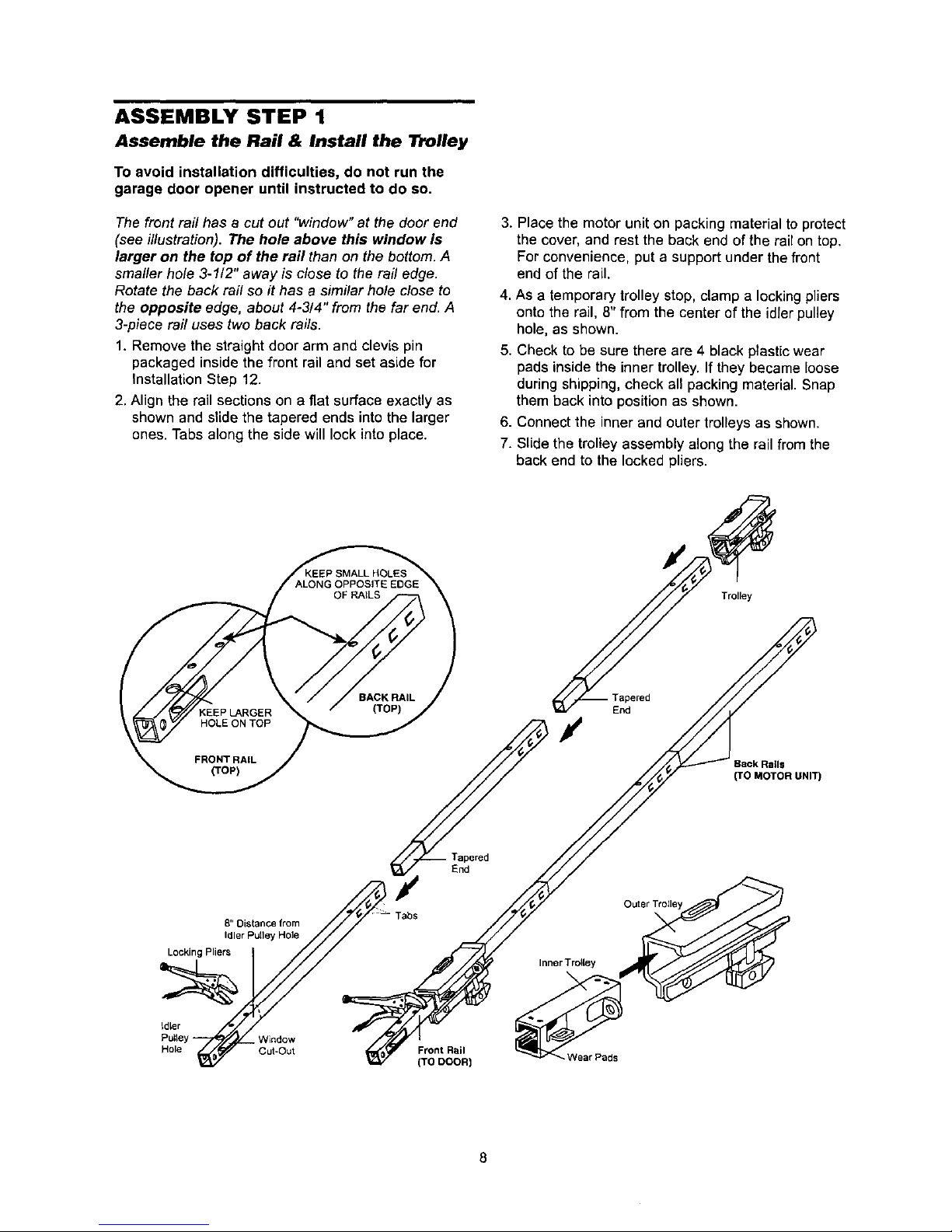
ASSEMBLY STEP 1
Assemble the Rail & Install the Trolley
To avoid installation difficulties, do not run the
garage door opener until instructed to do so,
The front rail has a cut out "window" at the door end
(see illustration). The hole above this window Is
larger on the top of the rail than on the bottom. A
smaller hole 3-112" away is close to the rail edge.
Rotate the back rail so it has a similar ho/e close to
the opposite edge, about 4-314" from the far end. A
3-piece rail uses two back rails.
1. Remove the straight door arm and clevis pin
packaged inside the front rail and set aside for
Installation Step 12.
2. Align the rail sections on a flat surface exactly as
shown and slide the tapered ends into the larger
ones. Tabs along the side will lock into place.
3. Place the motor unit on packing material to protect
the cover, and rest the back end of the rail on top.
For convenience, put a support under the front
end of the rail.
4. As a temporary trolley stop, clamp a locking pliers
onto the rail, 8" from the center of the idler pulley
hole, as shown.
5. Check to be sure there are 4 black plastic wear
pads inside the inner trolley. If they became loose
during shipping, check all packing material. Snap
them back into position as shown.
6. Connect the inner and outer trolleys as shown.
7. Slide the trolley assembly along the rail from the
back end to the locked pliers.
Trolley
End
Back Rails
(TO MOTOR UNIT)
Inner TrolLey
Wear Pads
8
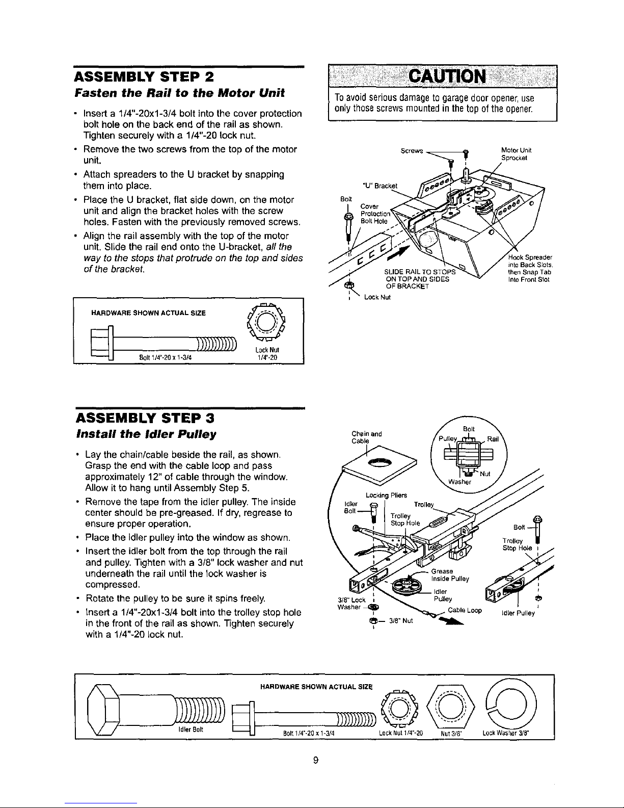
ASSEMBLY STEP 2
Fasten the Rail to the Motor Unit
• Insert a 1/4"-20xl-3/4 bolt into the cover protection
bolt hole on the back end of the rail as shown.
Tighten securely with a 1/4"-20 lock nut.
• Remove the two screws from the top of the motor
unit.
• Attach spreaders to the U bracket by snapping
them into place.
• Place the U bracket, flat side down, on the motor
unit and align the bracket holes with the screw
holes. Fasten with the previously removed screws.
• Align the rail assembly with the top of the motor
unit. Slide the rail end onto the U-bracket, all the
way to the steps that protrude on the top and sides
of the bracket.
HARDWARE SHOWN ACTUAL SIZE _'_'1
Bolt 1/4"-20 x 1-3/4 1/#-20
Toavoidseriousdamageto garagedooropener,use
onlythose screwsmountedin thetop of the opener.
Screws Motor Unit
Sprocket
"U" Bracket
Bolt
I Cover
SLIDE RAIL TO STOP
ON TOP AND SIDES
OF BRACKET
Lock Nut
into Back Slots1
then Snap Tab
IntoFrontSIot
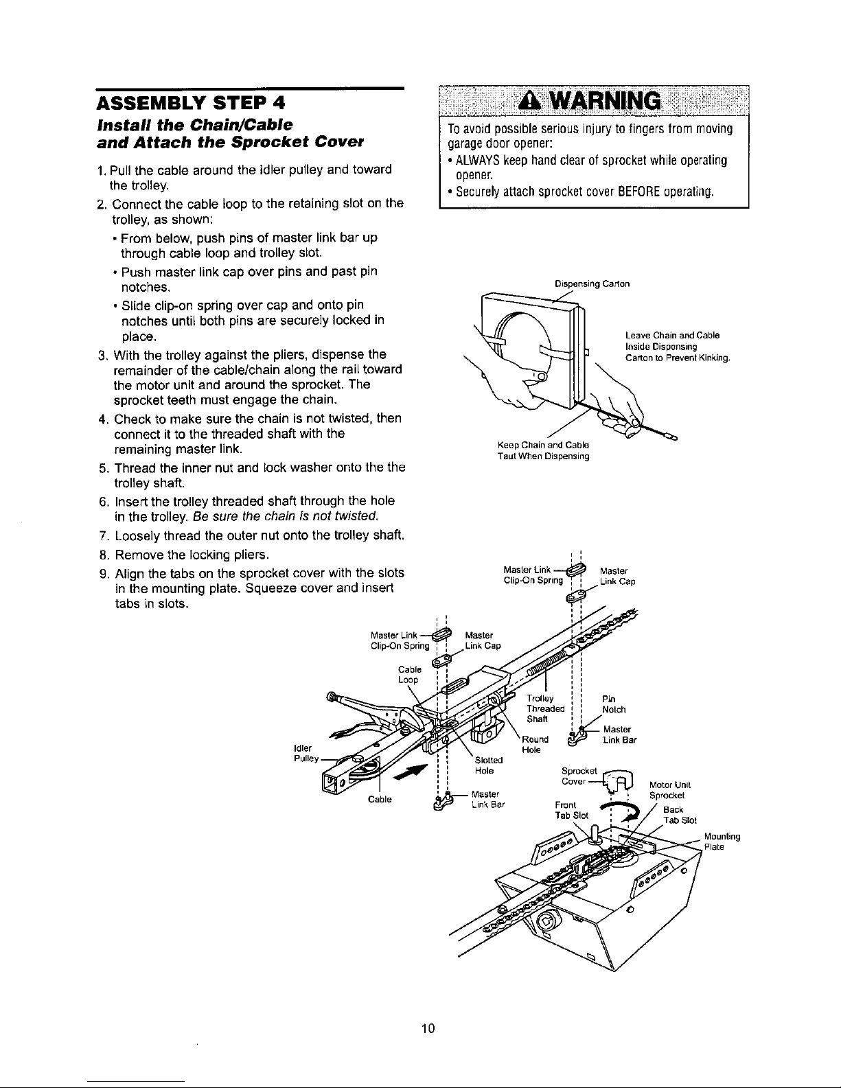
ASSEMBLY STEP 3
Install the Idler Pulley
• Lay the chain/cable beside the rail, as shown.
Grasp the end with the cable loop and pass
approximately 12" of cable through the window.
Allow it to hang until Assembly Step 5.
• Remove the tape from the idler pulley. The inside
center should be pre-greased. If dry, regrease to
ensure proper operation.
• Place the idler pulley into the window as shown.
• Insert the idler bo?tfrom the top through the rail
and pulley. Tighten with a 3/8" lock washer and nut
underneath the rail until the lock washer is
compressed.
• Rotate the pulley to be sure it spins freely.
• Insert a 1/4"-20xl-3/4 bolt into the trolley stop hole
in the front of the rail as shown. Tighten securely
with a 1/4"-20 lock nut.
Chain and
Cable
3/8"Lock
Washer_
Bolt --_
TrcJIley
St_p HoIe I
Grease _
Inside Pulley
i
Idler
Pulley
• Cable Loop Idler Pulley
HARDWARE SHOWN ACTUAL SIZE
Idler B01t Bolt1/4"-20x1-3/4 L0ckNut 1/4"-20 Nut3/8" LockWasher3/8"
9
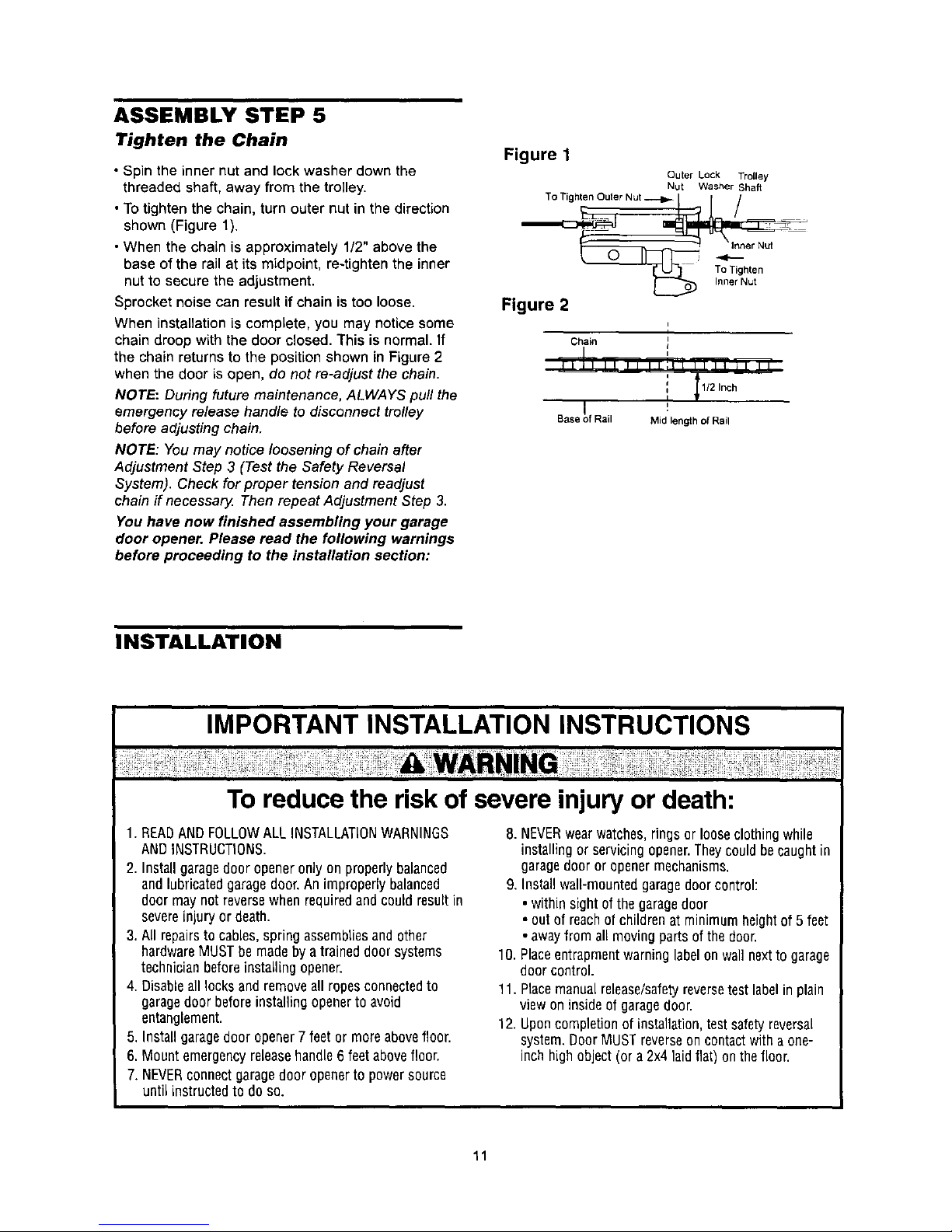
ASSEMBLY STEP 4
Install the Chain/Cable
and Attach the Sprocket Cover
1.Pull the cable around the idler pulley and toward
the trolley.
2. Connect the cable loop to the retaining slot on the
trolley, as shown:
• From below, push pins of master link bar up
through cable loop and trolley slot.
• Push master link cap over pins and past pin
notches.
• Slide clip-on spring over cap and onto pin
notches until both pins are securely locked in
place.
3. With the trolley against the pliers, dispense the
remainder of the cable/chain along the rail toward
the motor unit and around the sprocket. The
sprocket teeth must engage the chain.
4. Check to make sure the chain is not twisted, then
connect it to the threaded shaft with the
remaining master link.
5. Thread the inner nut and lock washer onto the the
trolley shaft.
6. Insert the trolley threaded shaft through the hole
in the trolley. Be sure the chain is not twisted.
7. Loosely thread the outer nut onto the trolley shaft.
8. Remove the locking pliers.
9. Align the tabs on the sprocket cover with the slots
in the mounting plate. Squeeze cover and insert
tabs in slots.
Cable
Loop
Toavoid possibleseriousinjury to fingersfrom moving
garagedoor opener:
•ALWAYSkeephandclearofsprocketwhile operating
opener.
• SecurelyattachsprocketcoverBEFOREoperating.
Dispensing Carton
Leave Chain and Cable
Inside Dispensin9
Carton to Prevent Kinking,
Keep Chain and Cable
Taut When Dispensing
i
I i
<
Master
Link Cap
Sha_
Pin
Notch
Idler
Cable
Link Bar
Hole
Hole Sprocket
Cover
---{r't [-'].,J Motor Unit
Master _" _; , Sprocket
Link Bar Front Back
Tab Slot ', Tab Slot
10
iii
ASSEMBLY STEP 5
Tighten the Chain
• Spin the inner nut and lock washer down the
threaded shaft, away from the trolley.
• Totighten the chain, turn outer nut in the direction
shown (Figure 1).
• When the chain is approximately 1/2" above the
base of the rail at its midpoint, re-tighten the inner
nut to secure the adjustment.
Sprocket noise can result if chain is too loose.
When installation is complete, you may notice some
chain droop with the door closed. This is normal. If
the chain returns to the position shown in Figure 2
when the door isopen, do not re-adjust the chain.
NOTE.: During future maintenance, ALWAYS pull the
emergency release handle to disconnect trolley
before adjusting chain.
NOTE: You may notice loosening of chain after
Adjustment Step 3 (Test the Safety Reversal
System). Check for proper tension and readjust
chain if necessar_ Then repeat Adjustment Step 3.
You have now finished assembling your garage
door opener. Please read the following warnings
before proceeding to the installation section:
Figure 1
Outer Lock TroLley
Nut Washer Shaft
To Tigh,en Outer Nut ---i_-1 [ /
'T°nTI_Nhrutn
Figure 2
,,
Chain I
I
i
tIJI II ,1 ,,i,_ 1111 il II
i II/2 Inch
/
Base _)fRail Mid length of Rail
INSTALLATION
IMPORTANT INSTALLATION INSTRUCTIONS
To reduce the risk of severe injury or death:
1. READANDFOLLOWALL INSTALLATIONWARNINGS
ANDINSTRUCTIONS.
2. Installgaragedoor openeronlyon properlybalanced
andlubricatedgaragedoor.An improperlybalanced
door maynot reversewhenrequiredand couldresultin
severeinjuryor death.
3. All repairsto cables,spring assembliesand other
hardwareMUSTbe maclebya traineddoor systems
technicianbeforeinstalling opener.
4. Disableall locksandremoveall ropesconnectedto
garagedoor beforeinstallingopenerto avoid
entanglement.
5. Installgaragedoor opener7 feet or more abovefloor.
6. Mount emergencyreleasehandle6 feetabovefloor.
7. NEVERconnectgaragedoor openerto powersource
until instructedto doso.
8. NEVERwearwatches,ringsor looseclothingwhile
installingor servicingopener.Theycouldbecaughtin
garagedoor or openermechanisms.
9. Installwall-mountedgaragedoorcontrol:
• withinsight of thegaragedoor
• out of reachofchildrenat minimumheightof 5 feet
• awayfrom all movingparts ofthe door.
10.Placeentrapmentwarninglabelon wall nextto garage
door control.
11. Placemanualrelease/safetyreversetestlabelin plain
viewon insideofgaragedoor.
12.Uponcompletionof installation,test safetyreversal
system.DoorMUSTreverseon contactwith a one-
inch highobject(or a 2x4 laidflat) onthefloor.
11
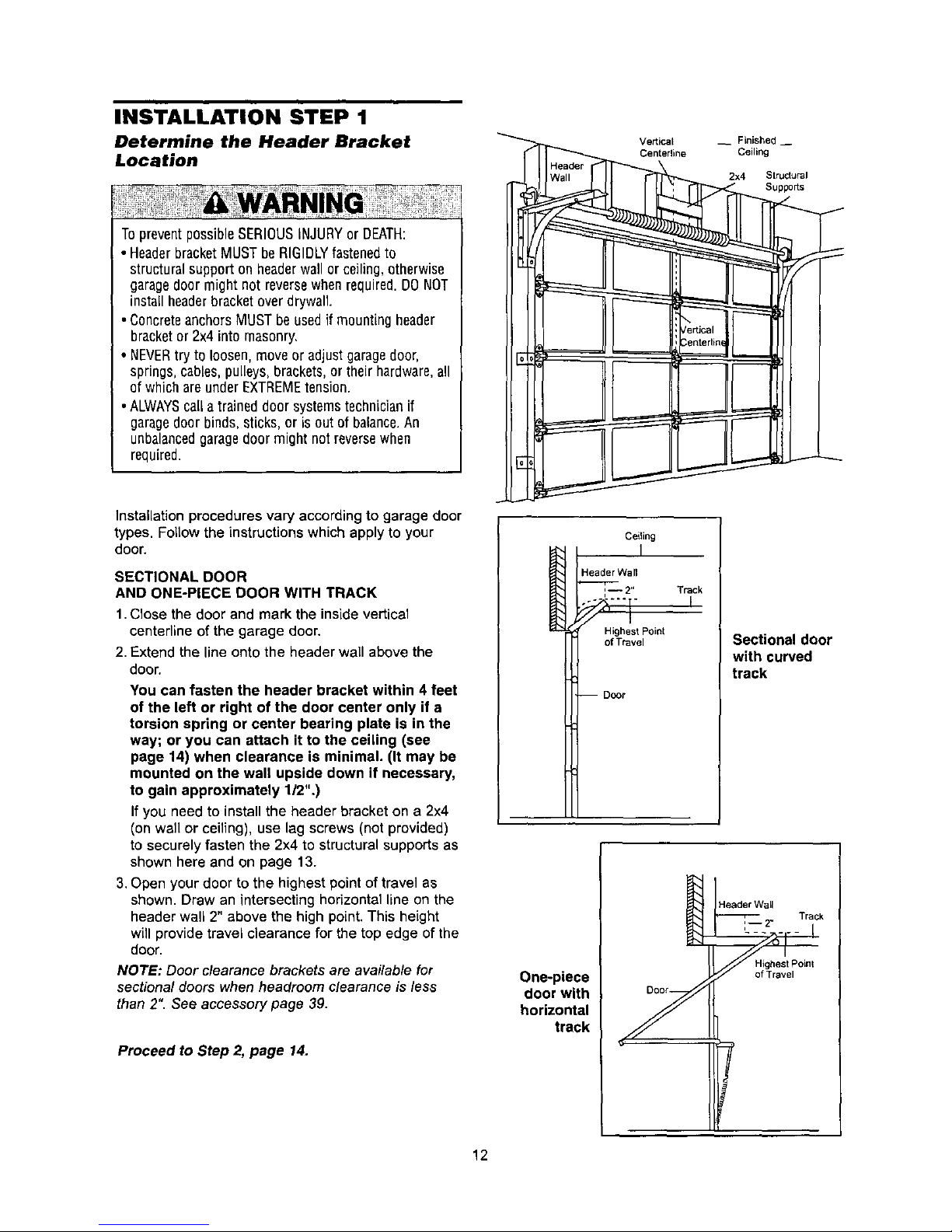
INSTALLATION STEP 1
Determine the Header Bracket
Location
TopreventpossibleSERIOUSiNJURYor DEATH:
• HeaderbracketMUSTbe RIGIDLYfastenedto
structural support on headerwall or ceiling,otherwise
garagedoor might not reversewhenrequired.DONOT
install headerbracketover drywall
•ConcreteanchorsMUSTbeusedif mountingheader
bracketor 2x4 into masonry,
• NEVERtry to loosen, moveor adjust garagedoor,
springs,cables,pulleys, brackets,or their hardware,all
of which areunder EXTREMEtension.
•ALWAYScall atrained door systemstechnicianif
garagedoor binds,sticks, or is outof balance.An
unbalancedgaragedoor might notreversewhen
required.
Installation procedures vary according to garage door
types. Follow the instructions which apply to your
door.
SECTIONAL DOOR
AND ONE-PIECE DOOR WITH TRACK
1.Close the door and mark the insidevertical
centerline of the garage door.
2.Extend the line onto the header wall above the
door.
You can fasten the header bracket within 4 feet
of the left or right of the door center only if a
torsion spring or center bearing plate is in the
way; or you can attach it to the ceiling (see
page 14) when clearance is minimal. (It may be
mounted on the wall upside down if necessary,
to gain approximately 1/2".)
If you need to install the header bracket on a 2x4
(on wall or ceiling), use lag screws (not provided)
to securely fasten the 2x4 to structural supports as
shown here and on page 13.
3. Open your door to the highest point of travel as
shown. Draw an intersecting horizontal line on the
header wall 2" above the high point, This height
will provide travel clearance for the top edge of the
door.
NOTE: Door clearance brackets are available for
sectional doors when headroom clearance is less
than 2". See accessory page 39.
Proceed to Step 2, page 14.
Vertical __ Finished-
Centerline Ceiling
2x4 StrucJural
Ceiling
I
Header Wall
._L--_2" Track
Highest Point
of Travel
-- DoOr
Sectional door
with curved
track
Header Wall
Track
'--2"
One-piece
door with
horizontal
track
of Travel
12
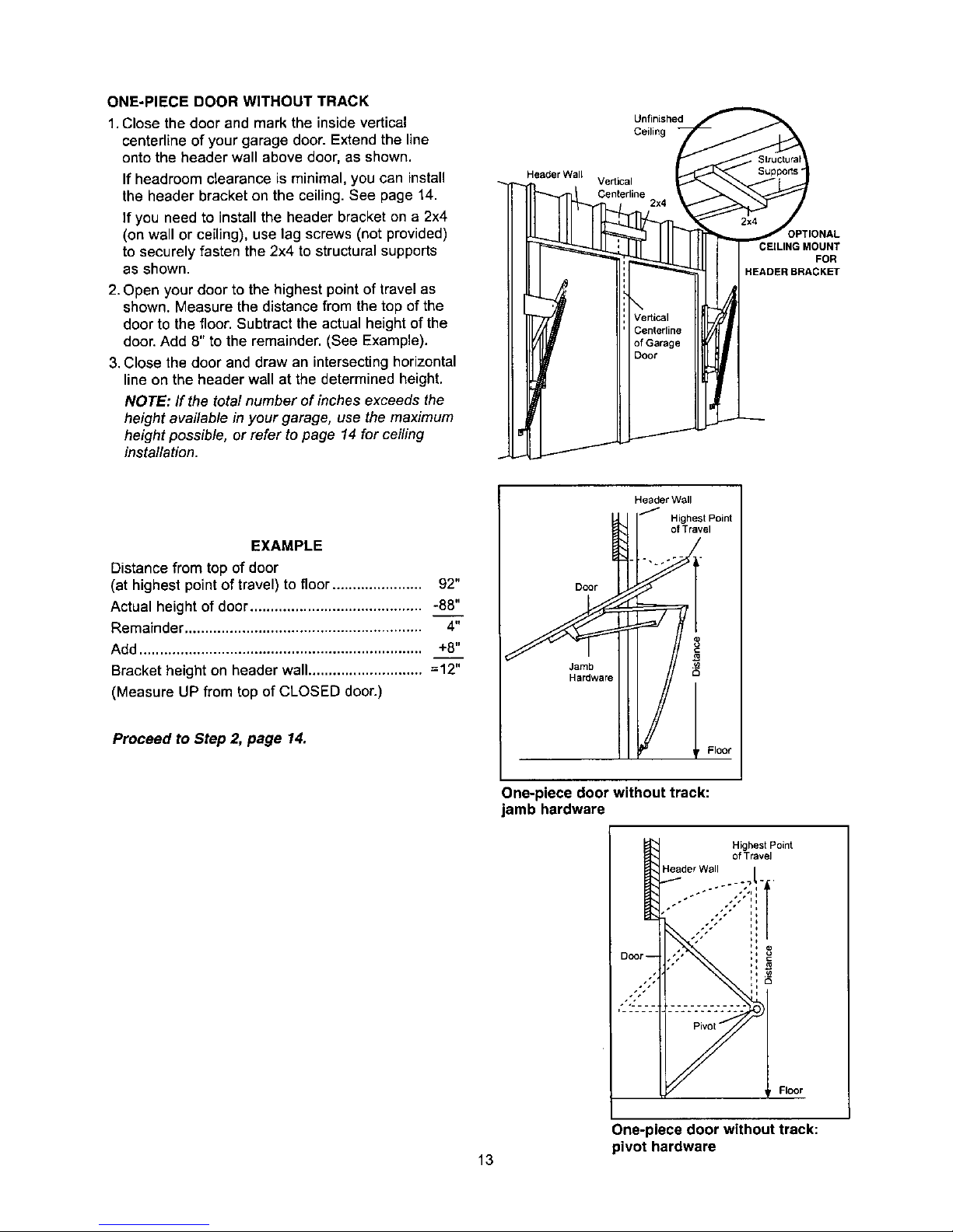
ONE-PIECE DOOR WITHOUT TRACK
1.Close the door and mark the insidevertical
centerline of your garage door. Extend the line
onto the header wall above door, as shown.
If headroom clearance is minimal, you can install
the header bracket on the ceiling. See page 14.
If you need to install the header bracket on a 2x4
(on wall or ceiling), use lag screws (not provided)
to securely fasten the 2x4 to structural supports
as shown.
2. Open your door to the highest point of travel as
shown. Measure the distance from the top of the
door to the floor. Subtract the actual height of the
door. Add 8" to the remainder. (See Example).
3.Close the door and draw an intersecting horizontal
line on the header wall at the determined height.
NOTE: If the total number of inches exceeds the
height available in your garage, use the maximum
height possible, or refer to page 14 for ceiling
installation.
Header Wall
Unfinished
Ceiling
Vedical
Centerline
CEILING MOUNT
FOR
HEADER BRACKET
EXAMPLE
Distancefrom top of door
(at highest pointof travel) to floor ...................... 92"
Actual height of door.......................................... -88"
Remainder.......................................................... 4"
Add ..................................................................... +8"
Bracket height on header wall............................ =12"
(Measure UP from top of CLOSED door.)
Proceed toStep _ page 14.
Header Wall
/ Highest Point
of Travel
"7
Q
One-piece door without track:
jamb hardware
Floor
One-piece door without track:
pivot hardware
13
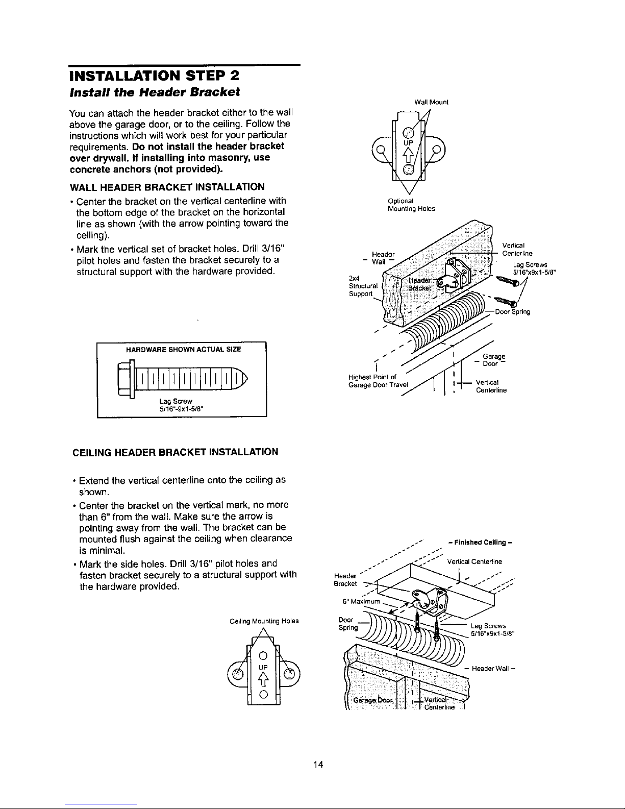
INSTALLATION STEP 2
Install the Header Bracket
You can attach the header bracket either to the wall
above the garage door, or to the ceiling. FoUow the
instructions which will work best for your particular
requirements. Do not install the header bracket
over drywall. If installing into masonry, use
concrete anchors (not provided).
WALL HEADER BRACKET INSTALLATION
• Center the bracket on the vertical centerline with
the bottom edge ofthe bracket on the horizontal
lineas shown (with the arrow pointingtowardthe
ceiling).
• Markthe vertical set of bracket holes, Drill3/16"
pilotholes and fasten the bracket securely to a
structuralsupportwith the hardware provided.
Wall Mount
Optional
Mounting Holes
Header
- Wall
2x4
Structural
Suppo_
Ve_ical
Centerline
Lag Scows
5/16"x9x1-518"
-Door Spring
HARDWARE SHOWN ACTUAL SIZE
LIl l llllllLlilLIl
Lag Screw
5/16"-9xl-5/8"
/
/
Highest Point of
Garage Door Travel
Garage
- Door -
Centerline
CEILING HEADER BRACKET INSTALLATION
• Extend the vertical centerline ontothe ceiling as
shown.
• Center the bracket on the vertical mark, no more
than 6" from the wall. Make sure the arrow is
pointing away from the wall. The bracket can be
mounted flush against the ceiling when clearance
is minimal.
• Mark the side holes. Drill 3/16" pilot holes and
fasten bracket securely to a structural support with
the hardware provided.
Ceiling Mounting Holes
Reader _
B_acket
6" Maximum
Door
- Finished Ceiling -
-- Lag Screws
5/16"xgxl-5/8"
- Header Wall-
Centerline
14
Header Bracket
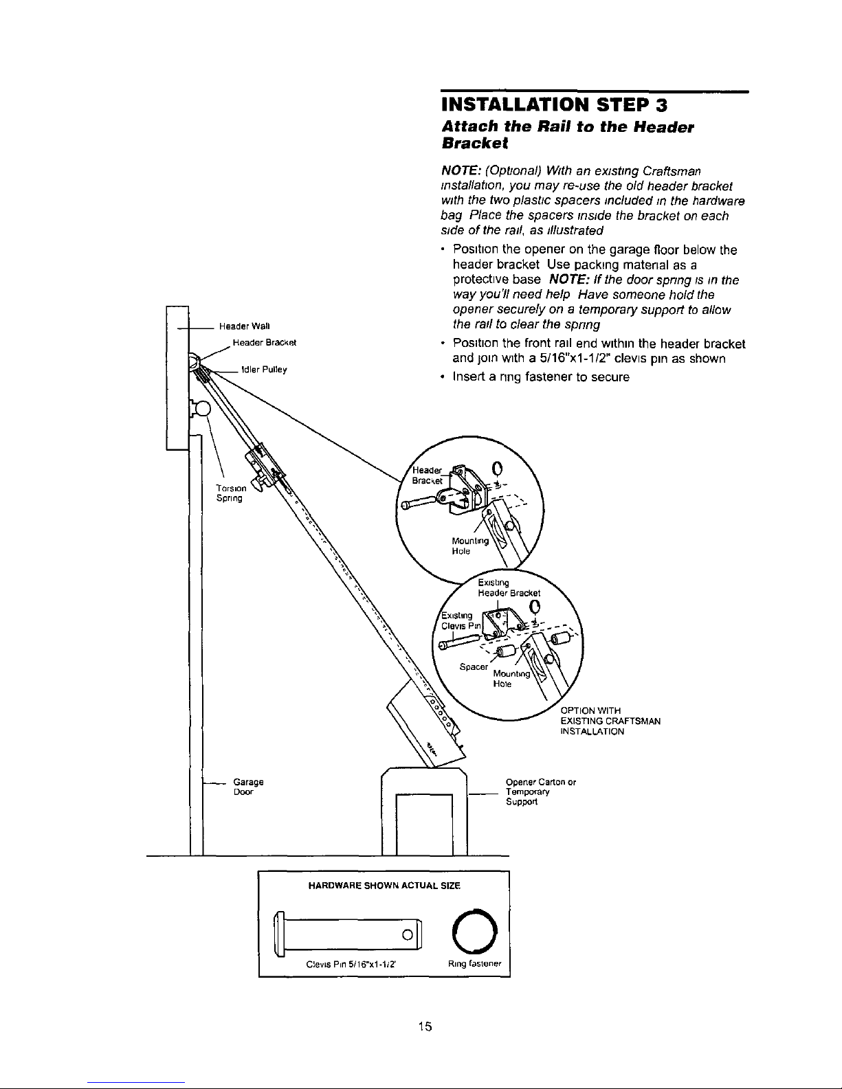
INSTALLATION STEP 3
Attach the Rail to the Header
Bracket
NOTE: (Opbonal) With an exlsbng Craftsman
mstallabon, you may re-use the old header bracket
with the two plastic spacers included fn the hardware
bag Place the spacers reside the bracket on each
side of the rail, as tllustrated
• Position the opener on the garage floor below the
header bracket Use packing material as a
protective base NOTE: If the door spnng ts m the
way you'll need help Have someonehold the
opener securely on a temporary support to allow
the rail to clear the spnng
• Position the front rail end within the header bracket
and join with a 5/16"x1-1/2" clevis pin as shown
• Insert a nng fastener to secure
Spring
0
Mounting
Hole
Header Bracket
0
HOle
3PTION WITH
EXISTING CRAFTSMAN
INSTALLATION
Garage
Door
OpenerCaKonor
__ Tempora_
Suppo_
HARDWARE SHOWN ACTUAL SIZE
O
Clev=s P=n5/16"xl-1/2' Ring fastener
15
iii
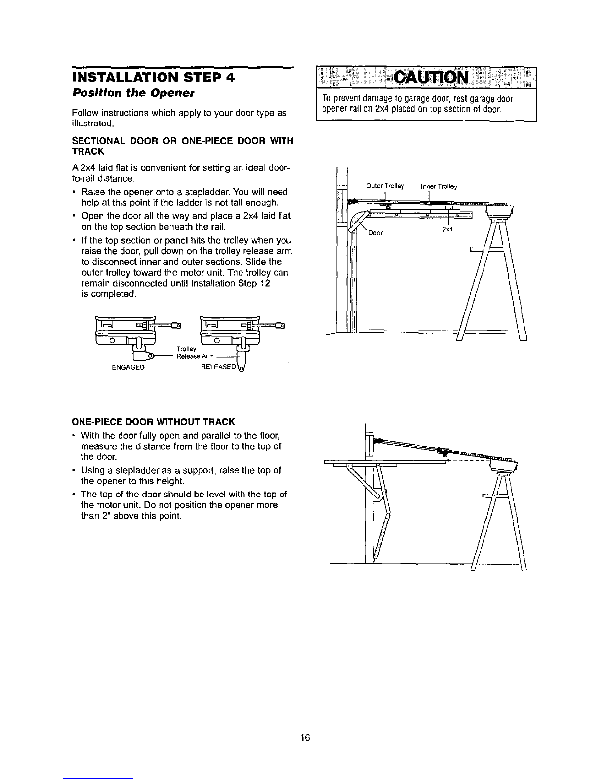
INSTALLATION STEP 4
Position the Opener
Follow instructions which apply to your door type as
illustrated.
SECTIONAL DOOR OR ONE-PIECE DOOR WITH
TRACK
A 2x4 laid flat is convenient for setting an ideal door-
to-rail distance.
• Raise the opener onto a stepladder. You willneed
help at this point if the ladder is not tall enough.
• Open the door all the way and place a 2x4 laid flat
on the top section beneath the rail.
• If the top section or panel hits the trolley when you
raise the door, pull down on the trolley release arm
to disconnect inner and outer sections. Slide the
outer trolley toward the motor unit. The trolley can
remain disconnected until Installation Step 12
is completed.
ENGAGED RELEASE_D
Outer Trolley Inner Trolley
ONE-PIECE DOOR WITHOUT TRACK
• With the door fully open and parallel to the floor,
measure the distance from the floor to the top of
the door.
• Using a stepladder as a support, raise the top of
the opener to this height.
• The top of the door should be level with the top of
the motor unit. Do not position the opener more
than 2" above this point.
i
16
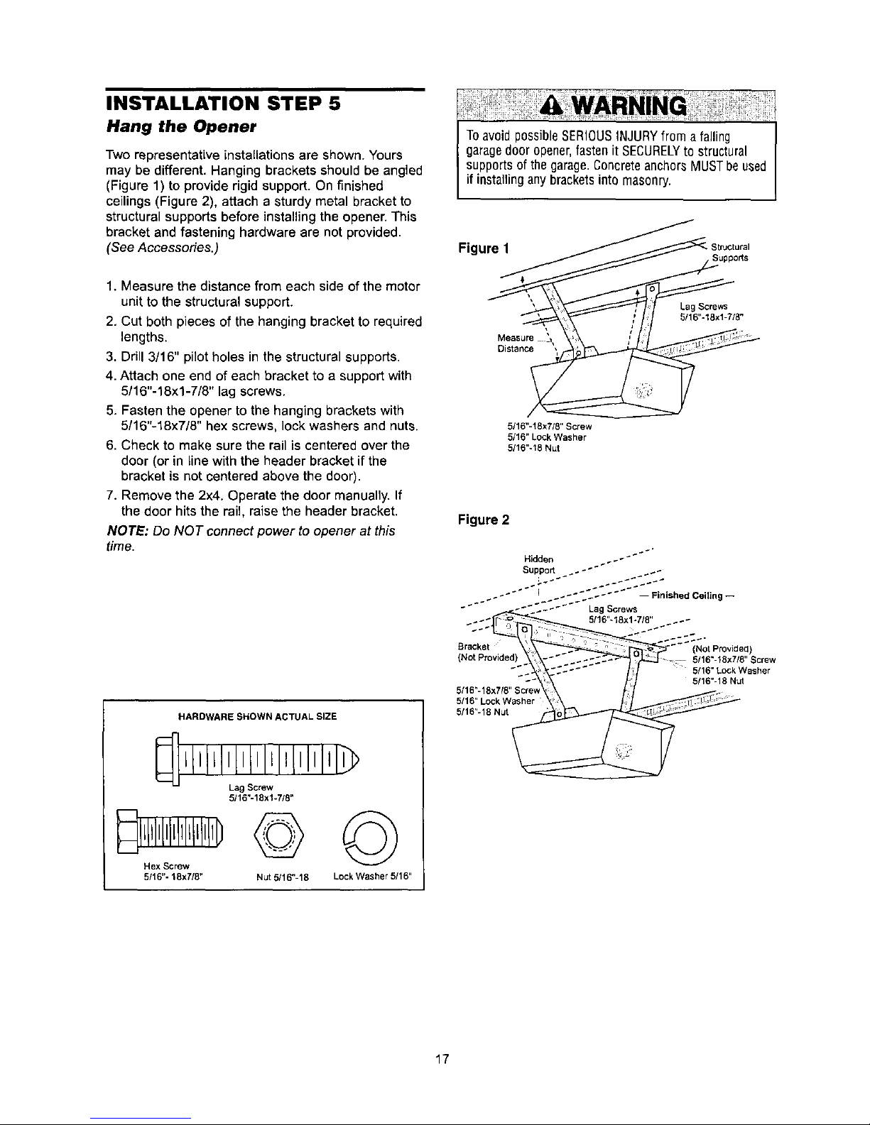
INSTALLATION STEP 5
Hang the Opener
Two representatLve installations are shown. Yours
may be different. Hanging brackets should be angled
(Figure 1) to provide rigid support. On finished
ceilings (Figure 2), attach a sturdy metal bracket to
structural supports before installing the opener. This
bracket and fastening hardware are not provided.
(See Accessories.)
ToavoidpossibleSERIOUSINJURYfrom a falling
garagedoor opener,fasten it SECURELYto structural
supportsofthe garage.ConcreteanchorsMUSTbeused
if installinganybracketsinto masonry.
Figure 1 Str'Jctural
1. Measure the distance from each side of the motor
unit to the structural support.
2, Cut both pieces of the hanging bracket to required
lengths.
3. Drill 3/16" pilot holes in the structural supports.
4. Attach one end of each bracket to a support with
5/16"-18xl-7/8" lag screws.
5. Fasten the opener to the hanging brackets with
5/16"-18x7/8" hex screws, lock washers and nuts.
6. Check to make sure the rail is centered over the
door (or in line with the header bracket if the
bracket is not centered above the door).
7. Remove the 2x4. Operate the door manually. If
the door hits the rail, raise the header bracket.
NOTE: Do NOT connect power to opener at this
time.
HARDWARESHOWNACTUALSIZE
Ll,l llLlllltI,LIlllll.
Lag Screw
5116"-18x1-7/8"
5/16"- 18x7/8" Nut 5/16"-18 Lock Washer 5/16"
Measure \,
Distance ',
Lag Screws
5/16"-18xl-7/8"
5/16"-!8×718"Screw
5/16" Lock Washer
5/16"-18 Nut
Figure 2
Hidden ..-
.-_ 5/16"-18xl-718" _.-
Bracket --_ (NotProvided)
(Not Provided)_- _ . .- :::..-"_'_ _._._J _ 5/16"-18x7/e" Screw
"'_ 5/16" Lock Washer
"-- 5/16"-18 Nut
5/16"-18x718"$crew
5/165/16"LockWasher18_i_, .TI::]_ !_;'_'
17
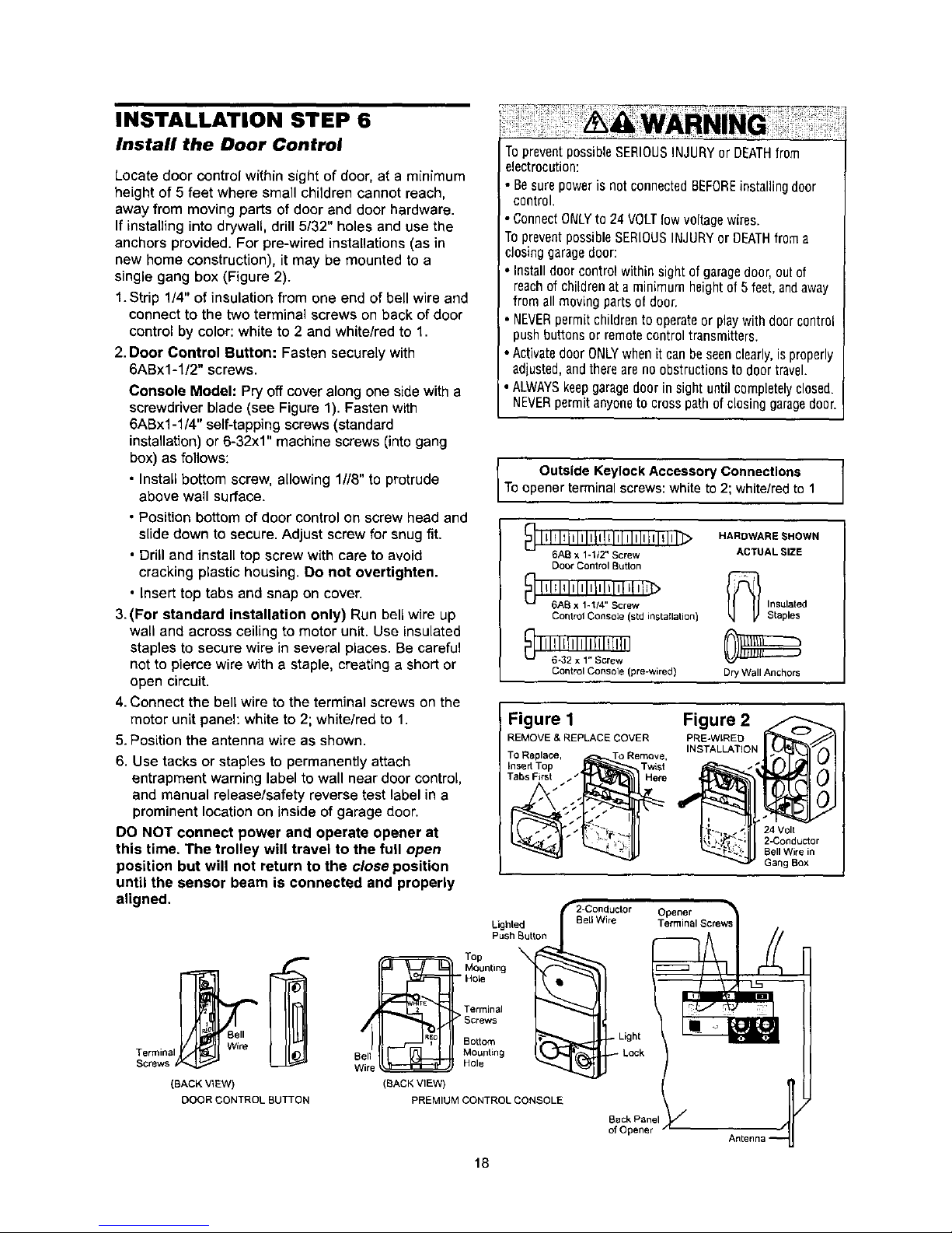
INSTALLATION STEP 6
Install the Door Control
Locate door control within sight of door, at a minimum
height of 5 feet where small children cannot reach,
away from moving parts of door and door hardware.
If installing into drywall, drill 5/32" holes and use the
anchors provided. For pre-wired installations (as in
new home construction), it may be mounted to a
single gang box (Figure 2).
1.Strip 1/4" of insulation from one end of bell wire and
connect to the two terminal screws on back of door
control by color: white to 2 and white/red to 1.
2. Door Control Button: Fasten securely with
6ABx1-l/2" screws.
Console Model: Pry offcover along one side witha
screwdriver blade (see Figure 1). Fasten with
6ABx1-1/4" self-tapping screws (standard
installation) or 6-32x1" machine screws (into gang
box) as follows:
• Install bottom screw, allowing 1//8" to protrude
above wall surface.
• Position bottom of door control on screw head and
slide down to secure. Adjust screw for snug fit.
• Drill and install top screw with care to avoid
cracking plastic housing. 13onot overtighten.
• Insert top tabs and snap on cover.
3.(For standard installation only) Run bell wire up
wall and across ceiling to motor unit. Use insulated
staples to secure wire in several places. Be careful
not to pierce wire with a staple, creating a short or
open circuit.
4.Connect the bell wire to the terminal screws on the
motor unit panel: white to 2; white/red to 1.
5.Position the antenna wire as shown.
6. Use tacks or staples to permanently attach
entrapment warning label to wall near door control,
and manual release/safety reverse test label in a
prominent location on inside of garage door.
DO NOT connect power and operate opener at
this time, The trolley will travel to the full open
position but will not return to the close position
until the sensor beam is connected and properly
aligned.
TopreventpossibleSERIOUSINJURYorDEATHfrom
electrocution:
• Besurepoweris not connectedBEFOREinstallingdoor
control.
• ConnectONLYto 24 VOLTlow voltagewires.
TopreventpossibleSERIOUSINJURYor DEATHfroma
closinggaragedoor:
• Installdoorcontrolwithinsightofgaragedoor,outof
reachofchildrenat aminimumheightof5feet,andaway
fromall movingpartsofdoor.
• NEVERpermitchildrento operateor playwithdoorc0ntrol
pushbuttonsor remotecontroltransmitters.
• ActivatedoorONLYwhenitcanbeseenclearly,is properly
adjusted,andthereareno obstructionstodoortravel.
ALWAYSkeepgaragedoor insight untilcompletelyclosed.
NEVERpermitanyoneto crosspathof closinggaragedoor.
Outside Keylock Accessory Connections
To opener terminal screws: white to 2; white/red to 1
_] I_!ll_illlllliltltl Illliillllil_>
6AB x 1-1/2" Screw
Door Control Button
H; IAI212Il1111/12,,tiSIcl'el/VJ_
Control Console (std installation)
I 116!; I21IxII,!': Ictrle!; II
Control Console (pre-wired)
HARDWARE SHOWN
ACTUAL SIZE
_ nsulated
Staples
Dry Wall Anchors
Figure 1
REMOVE & REPLACE COVER
TO Replace, To Remove,
Insert Top Twist
Tabs First__._._. Here
Figure 2
PRE-WtRED
INSTALLATION
24 Volt
2-Conductor
BellWire in
Gang Box
Lighted
Push Button
Bell
Terminal Wire
Screws
(BACK V_EW)
DOOR CONTROL BUTTON
:_F==_===_== Top
_v Mounting
- Hole
. > Terminal
/ _ Sorews
Bottom
Ben Mounting
Wire _ Hole
(BACK VIEW)
PREMIUM CONTROL CONSOLE
Back Panel
of Opener
18
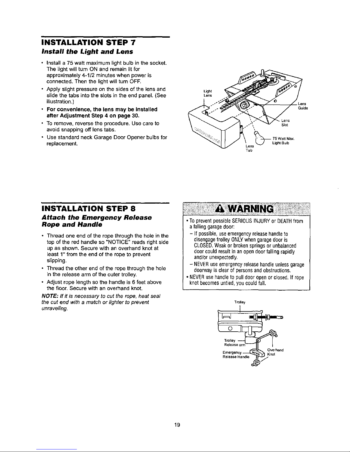
INSTALLATION STEP 7
Install the Light and Lens
• Install a 75 watt maximum light bulb in the socket.
The light will turn ON and remain lit for
approximately 4-1/2 minutes when power is
connected. Then the light will turn ore
• Apply slight pressure on the sides of the lens and
slide the tabs into the slots in the end panel. (See
illustration .)
• For convenience, the lens may be installed
after Adjustment Step 4 on page 30.
• To remove, reverse the procedure. Use care to
avoid snapping off lens tabs.
• Use standard neck Garage Door Opener bulbs for
replacement.
Light
Lens I
I*" Lens
" . Guide
_g._ Lens
ens Light Bulb
Tab
INSTALLATION STEP 8
Attach the Emergency Release
Rope and Handle
• Thread one end of the rope through the hole in the
top of the red handle so "NOTICE" reads right side
up as shown. Secure with an overhand knot at
least 1" from the end of the rope to prevent
slipping.
• Thread the other end of the rope through the hole
in the release arm of the outer trolley.
• Adjust rope length so the handle is 6 feet above
the floor. Secure with an overhand knot,
NOTE: flit is necessary to cut the rope, heat seal
the cut end with a match or lighter to prevent
unraveling.
• TopreventpossibleSERIOUSINJURYor DEATHfrom
a falling garagedoor:
- If possible,useemergencyreleasehandleto
disengagetrolley ONLYwhen garagedooris
CLOSED.Weakor brokenspringsor unbalanced
door couldresultin anopendoor fallingrapidly
and/orunexpectedly.
- NEVERuseemergencyreleasehandleunlessgarage
doorwayis clearof personsandobstructions.
• NEVERusehandleto pull door openor closed,If rope
knot becomesuntied,you couldfall.
Trolley
Trolley
Overhand
Eme_genc Knot
Release Handle
19
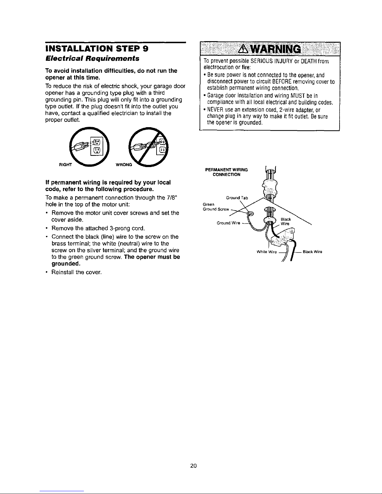
INSTALLATION STEP 9
Electrical Requirements
To avoid installation difficulties, do not run the
opener at this time.
To reduce the risk of electric shock, your garage door
opener has a grounding type plug with a third
grounding pin. This plug will only fit into a grounding
type outlet. If the plug doesn't fit into the outlet you
have, contact a qualified electrician to install the
proper outlet.
If permanent wiring is required by your local
code, refer to the following procedure.
To make a permanent connection through the 7/8"
hole in the top of the motor unit:
• Remove the motor unit cover screws and set the
cover aside,
• Remove the attached 3-prong cord.
• Connect the black (line) wire to the screw on the
brass terminal; the white (neutral) wire to the
screw on the silver terminal; and the ground wire
to the green ground screw. The opener must be
grounded.
• Reinstall the cover.
TopreventpossibleSERIOUSINJURYor DEATHfrom
electrocutionor fire:
• Besure poweris notconnectedtothe opener,and
disconnectpowerto circuit BEFOREremovingcoverto
establishpermanentwiring connection.
• Garagedoor installationandwiring MUSTbe in
compliancewith all localelectricaland buildingcodes.
• NEVERuseanextensioncord, 2-wire adapter,or
changeplug in anywayto makeit fit outlet. Besure
theopeneris grounded.
PERMANENT WIRING
CONNECTION
Ground Tab
Green
Ground Screw
White /
2O
INSTALLATION STEP 10
Install The Safety Reversing Sensor
The safety reversing sensor must be connected
and aligned correctly before the garage door
opener will move in the down direction,
IMPORTANT INFORMATION ABOUT
THE SAFETY REVERSING SENSOR
When properly connected and aligned, the sensor
will detect an obstacle in the path of its electronic
beam. The sending eye (with an orange indicator
light) transmits an invisible light beam to the
receiving eye (with a green indicator light). If an
obstruction breaks the light beam while the door is
closing, the door will stop and reverse to full open
position, and the opener lights will flash 10 times.
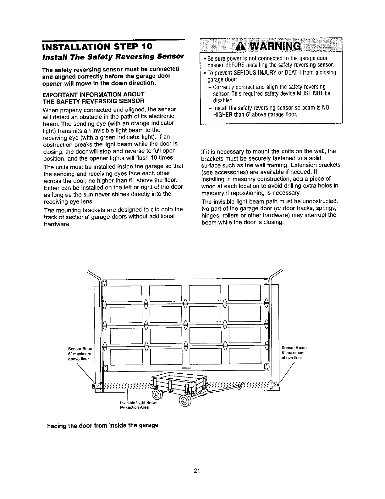
The units must be installed inside the garage so that
the sending and receiving eyes face each other
across the door, no higher than 6" above the floor.
Either can be installed on the left or right of the door
as long as the sun never shines directly into the
receiving eye lens.
The mounting brackets are designed to clip onto the
track of sectional garage doors without additional
hardware.
• Besurepowerisnot connectedto thegaragedoor
openerBEFOREinstalling the safetyreversingsensor.
• TopreventSERIOUSINJURYor DEATHfrom aclosing
garagedoor:
- Correctlyconnectand alignthesafety reversing
sensor.ThisrequiredsafetydeviceMUSTNOTbe
disabled.
- InstallthesafetyreversingsensorsobeamisNO
HIGHERthan 6"above garagefloor.
If it is necessary to mount the units on the wall, the
brackets must be securely fastened to a solid
surface such as the wall framing. Extension brackets
(see accessories) are available if needed. If
installing in masonry construction, add a piece of
wood at each location to avoid drilling extra holes in
masonry if repositioning is necessary.
The invisible light beam path must be unobstructed.
No part of the garage door (or door tracks, springs,
hinges, rollers or other hardware) may interrupt the
beam while the door is closing.
!i
Invisible Light Seam
Protection Area
SensorBeam
6"maximum
above floor
Facing the door from inside the garage
21
INSTALLING THE BRACKETS
Be sure power to the opener is disconnected.
Installand align the brackets so the sensors willface
each other across the garage door,with the beam no
higherthan 6"above the floor.They may be installed
in one of threeways, as follows.
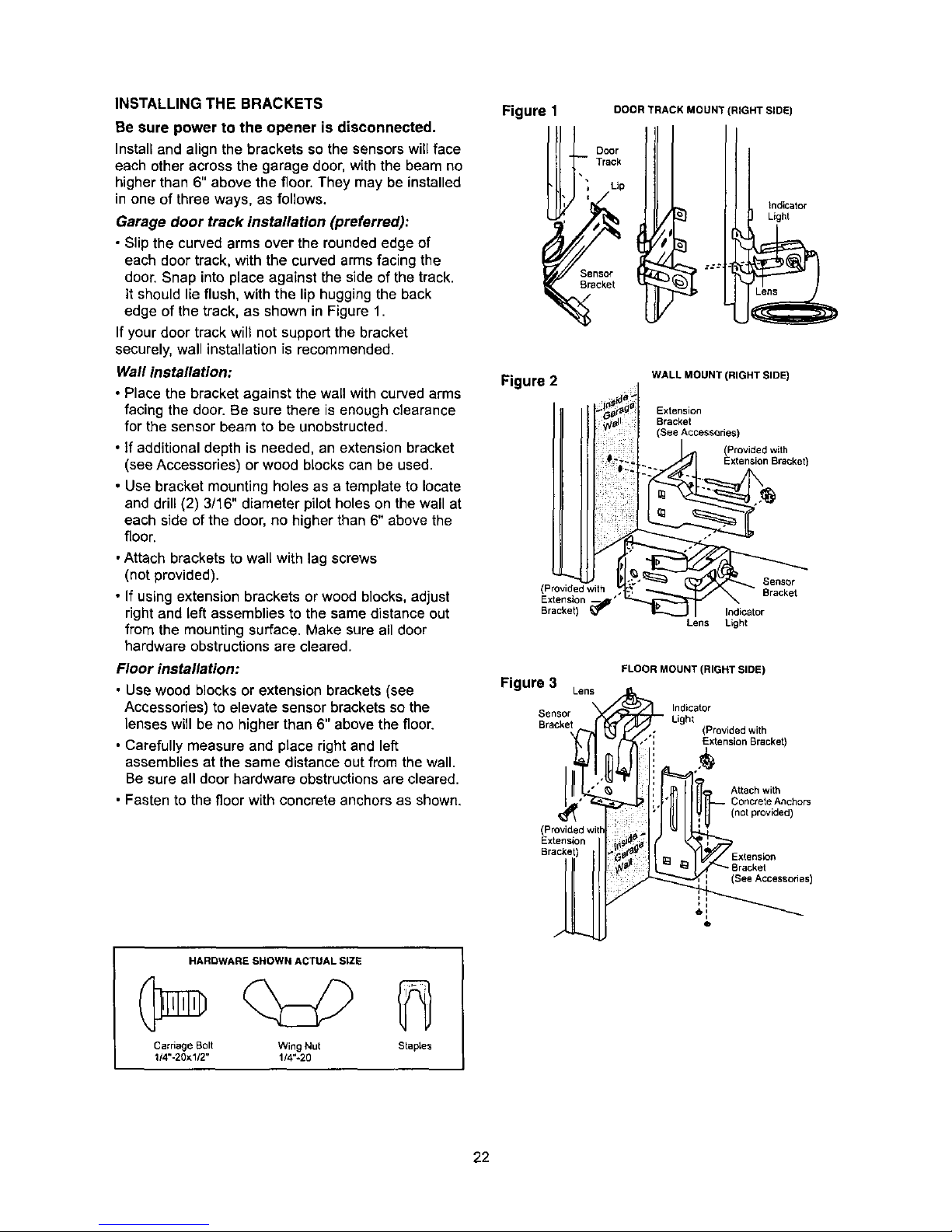
Garage door track installation (preferred):
• Slip the curved arms over the rounded edge of
each door track, with the curvedarms facing the
door. Snap intoplace against the side of the track.
it should lie flush, withthe lip huggingthe back
edge of the track, as shown in Figure 1.
Ifyour door trackwilt not supportthe bracket
securely,wall installationis recommended.
Wall installation:
• Place the bracket against the wall with curved arms
facing the door. Be sure there is enough clearance
for the sensor beam to be unobstructed.
• if additional depth is needed, an extension bracket
(see Accessories) or wood blocks can be used.
• Use bracket mounting holes as a template to locate
and drill (2) 3/16" diameter pilot holes on the wall at
each side of the door, no higher than 6" above the
floor.
• Attach brackets to wall with lag screws
(not provided).
• If using extension brackets or wood blocks, adjust
right and left assemblies to the same distance out
from the mounting surface. Make sure all door
hardware obstructions are cleared.
Floor installation:
• Use wood blocks or extension brackets (see
Accessories) to elevate sensor brackets so the
lenses will be no higher than 6" above the floor.
• Carefully measure and place right and left
assemblies at the same distance out from the wall.
Be sure all door hardware obstructions are cleared.
• Fasten to the floor with concrete anchors as shown,
HARDWARE SHOWN ACTUAL SIZE
Carriage Bolt Wing Nut Staples
1/4"-20x1/2" 1/4"o20
Figure 1
DOOR TRACK MOUNT (RIGHT SLOE)
Door
Track
_ensor
Bracket
indicator
Light
Figure 2
(Provided with
Extension --
Bracket) _"
WALL MOUNT (RIGHT SIDE)
Extension
Bracket
(See Accessories)
(Provided with
Extension Bracket)
Sensor
Bracket
Indicator
Lens Light
Figure 3 Lens
Sensor
Bracket
FLOOR MOUNT (RIGHT SIDE)
Indicator
Light
(Provided with
"*' Extension Sracket)
Attach with
Concrete Anchors
not provided)
, i**e°sie°
] Bracket
See Accessones)
t i
Q
22
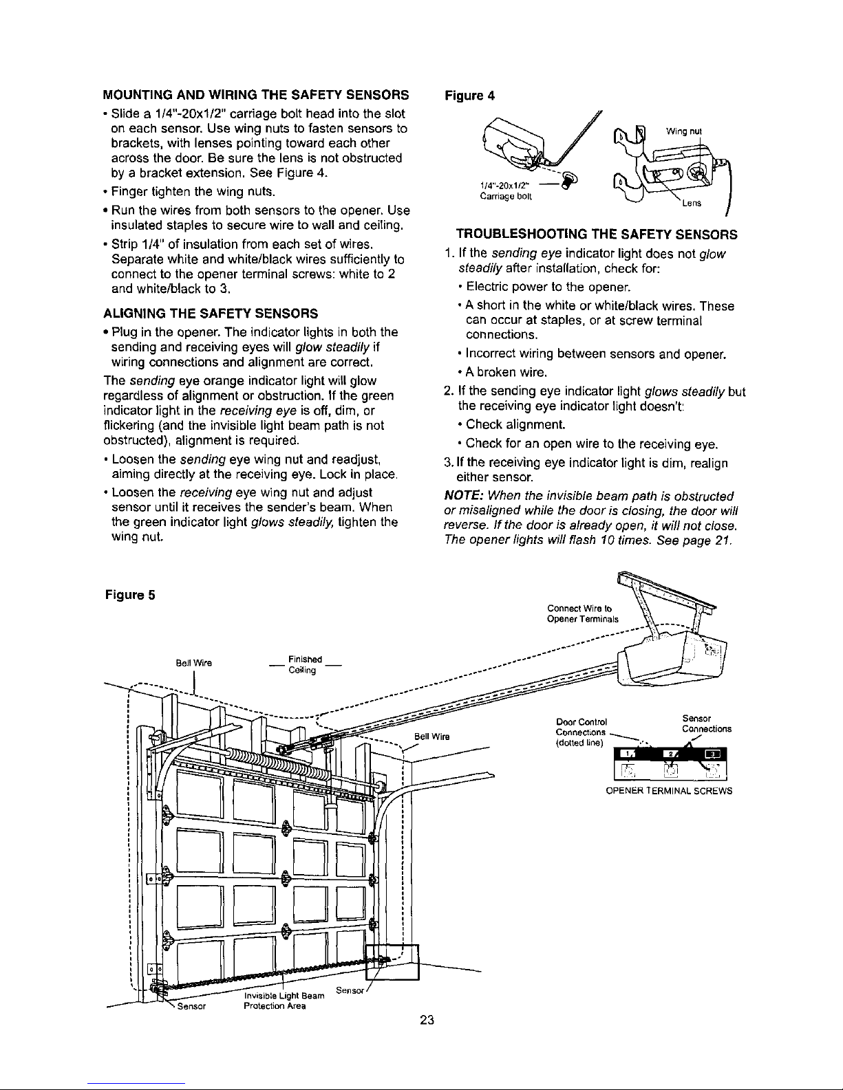
MOUNTING AND WIRING THE SAFETY SENSORS
• Slide a 1/4"-20x1/2" carriage bolt head into the slot
on each sensor. Use wing nuts to fasten sensors to
brackets, with lenses pointing toward each other
across the door. Be sure the lens is not obstructed
by a bracket extension. See Figure 4.
• Finger tighten the wing nuts.
• Run the wires from both sensors to the opener. Use
insulated staples to secure wire to wall and ceiTing.
• Strip 1/4" of insulation from each set of wires.
Separate white and white/black wires sufficiently to
connect to the opener terminal screws: white to 2
and white/black to 3.
ALIGNING THE SAFETY SENSORS
• Plug in the opener.The indicator lights in both the
sending and receiving eyes will glow steadily if
wiring connections and alignment are correct.
The sending eye orange indicator light will glow
regardless of alignment or obstruction. If the green
indicator light in the receiving eye is off, dim, or
flickering (and the invisible light beam path is not
obstructed), alignment is required.
• Loosen the sending eye wing nut and readjust,
aiming directly at the receiving eye. Lock in place.
• Loosen the receiving eye wing nut and adjust
sensor until it receives the sender's beam. When
the green indicator light glows steadily, tighten the
wing nut.
Figure 4
114"-20xl/2" _
Cardage bolt
Wing nut
TROUBLESHOOTING THE SAFETY SENSORS
1. If the sending eye indicatorlightdoes not g/ow
steadily after installation, checkfor:
• Electricpower to the opener.
• A short in the white or white/blackwires.These
can occur at staples, or at screw terminal
connections.
• Incorrectwiring between sensors and opener.
• A broken wire.
2. If the sending eye indicatorlightg/ows steadily but
the receivingeye indicatorlight doesn't:
• Check alignment.
• Check for an open wire to the receiving eye.
3. If the receivingeye indicatorlight is dim, realign
either sensor.
NOTE: When the invisib/ebeam path is obstructed
or misa/igned while the dooris c/osing, the door wi//
reverse. /f the door is a/ready open, it wi// not dose.
The opener /ights willflash 10 times. See page 21.
Figure 5
Connect Wire to
Opener Terminals
Bell Wire __ Finished __
Ceiling
Bell Wire
Door Control Sensor
Connections _ Connections
(dotted line) .'- J
%
OPENER TERMINAL SCREWS
Sellsot"
Invisible Light Seam
Protection Area
23
 Loading...