

Craftsman 13953716 Owner’s Manual
Touch Code Lock
NIodel 139.53716
o
n
KEYBOARD
The Touch Code Lock consists of a keyboard and a console The keyboard sends a coded signal from outside the garage
The console fastens to an inside garage wall it receives the 4-digit programmed coded signal and _tarts the door opener
The Touch Code Lock will work with most Genie "Push Twice to Operate" openers if you press any other digit after
you enter the 4-digit programmed code°
NOTE: CABLE CONNECTOR HOLE IS LOCATED ON LEFT SIDE OF CONSOLE IF POSSIBLE, INSTALL TOUCH CODE LOCK ON LEFT
SIDE OF GARAGE (DETERMINED BY FACING GARAGE FROM OUTSIDE) IF INSTALLED ON RIGHT SIDE OF GARAGE, CABLE MUST
BE ROUTED OVER OR UNDER CONSOLE
CONSOLE
FEATURES OF THE DIGITAL TOUCH CODE LOCK
Personalized Code: 10,000 possible combinations Code
can be changed easily if desired
Operation: Opener activates when programmed code is
entered on the keyboard
The user has 10 seconds from the time the first number
is pressed to enter the 4-digit code
If incorrect numbers are accidentally pressed, a5 second
interval is necessary before starting over.
Power Supply: Operates from the garage door opener
power with a battery b&ck-up for code memory and light-
ed keyboard Unit wiU not operate without battery
Installation: Simple to install in 5 easy steps
Console: Provides an additional push button controt to
operate door from inside garage
Keyboard; Thegarage door can be operated after a valid
code entry by pressing ANY single key AS LONG AS THE
KEYBOARD LIGHT REMAINS ON..
Keyboard Illuminates and remains lit for 10seconds when
ANY number is pressed in darkness this feature allows
user to press ANY number before entering the 4-digit code
IMPORTANT NOTE: When illumination is needed,
avoid pressing keyboard area which contains the first
code number.
DISCONNECT THE POWER TO THE GARAGE DOOR OPENER BEFORE BEGINNING INSTALLATION.
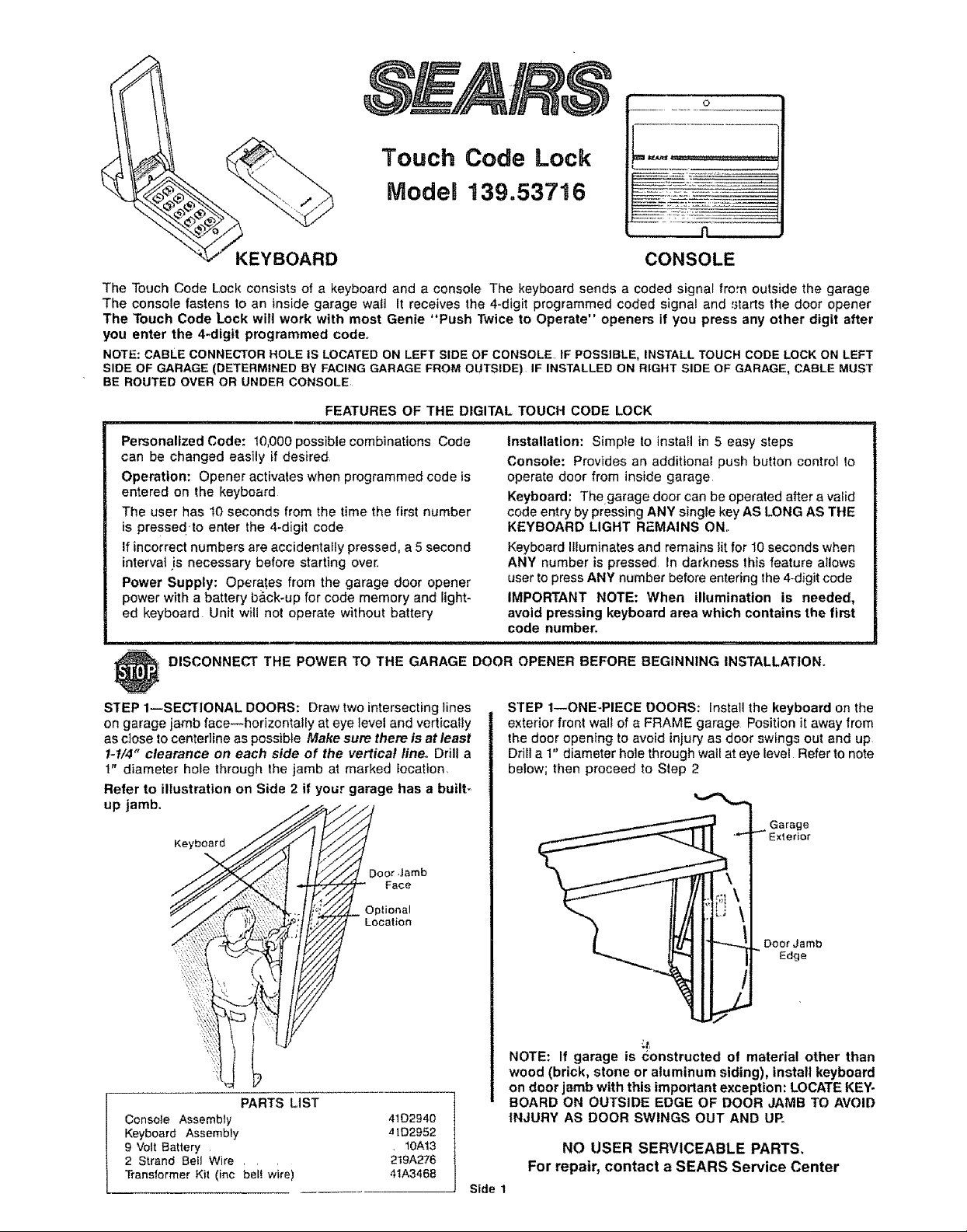
STEP 1--SECTIONAL DOORS: Draw two intersecting lines
on garage jamb face--horizontally at eye level and vertically
as close to centedine as possibfe Make sum there is at least
1-t/4" clearance on each side of the vertical line. Drill a
1" diameter hole through the jamb at marked location.
STEP 1--ONE-PIECE DOORS: install the keyboard on the
exterior front wal! of a FRAME garage Position it away from
the door opening to avoid injury as door swings out and up
Drill a 1" diameter hole through wall at eye level Refer to note
below; then proceed to Step 2
Refer to illustration on Side 2 if your garage has a built_
up jamb.
Garage
Keyboard
riot
Optional
Location
PARTS LIST
Conso}e Assembly 41D2940
Keyboard Assembly ,HD2952
9 Volt Battery 10A13
2 Strand Betl Wire , , , 219A276
Transformer Kit (inc bel! wire) 41A3468
Doer Jamb
Edge
NOTE: If garage is Constructed of material other than
wood (brick, stone or aluminum siding), install keyboard
on door jamb with this important exception: LOCATE KEY-
BOARD ON OUTSIDE EDGE OF DOOR JAMB TO AVOID
INJURY AS DOOR SWINGS OUT AND UP_
NO USER SERVICEABLE PARTS.
For repair, contact a SEARS Service Center
Side 1
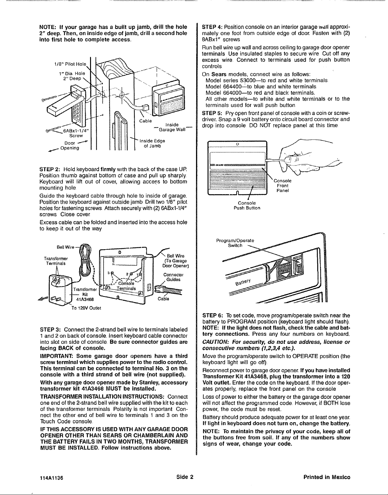
NOTE: if your garage has a built up jamb, drill the hole
2" deep. Then, on inside edge of jamb, drill a second hole
into first hole to complete access_
l/8" Pilot Hole I _'_--_
1" Dia Hole N \,J,_\"_
"4 1"V.i,--..__'_. fjfq.....
t_._"-_JIr I 1 1J I1_", I CabLe
Screw I I IL!III!IM
ooo,--_ I I I IIit tl rlnsi,deEdge
STEP 2: Hold keyboard firmly with the back of the case UP.
Position thumb against bottom of case and pull up sharply
Keyboard will lift out of cover, allowing access to bottom
mounting hole
Guide the keyboard cable through hole to inside of garage.
Position the keyboard against outside jamb Drill two 1/8" pilot
holes for fastening screws Attach securely with (2) 6ABx1-1/4"
screws CIose cover
Excess cable can be folded and inserted intotheaccess ho_e
to keep it out of the way
STEP 4: Position console on an interior garage wall approxi-
mately one foot from outside edge of door. Fasten with (2)
8ABxl" screws
Run bell wire up wall and across ceiling to garage door opener
terminals Use insulated staples to secure wire Cut off any
excess wire Connect to terminals used for push button
controls
On Sears models, connect wire as follows:
Model series 53000--to red and white terminals
Model 664400-Lto blue and white terminals
Modei 664000--to red and black terminals.
All other models_to white and white terminals or to the
terminals used for wall push button
STEP 5: Pry open front panel of console with a coin or screw-
driver. Snap a 9 voIt battery onto circuit board connector and
drop into console DO NOT replace panel at this time
Console
Push Button
Transformer (To Garage
Bell Wife
TerminaJs Doer Opener)
Con ne,;,"l_Or
Guides
Kit
4'_A3468 Cable
To 120V Ou#et
STEP 3: Connect the 2-strand bell wire to terminals labeled
1 and 2 on back of console, insert keyboard cable connector
into slot on side of console Be sum connector guides are
facing BACK of consote.
IMPORTANT; Some garage door openers have a third
screw terminal which supplies power to the radio control.
This terminal can be connected to terminal No. 3 on the
console with a third strand of bell wire (not supplied).
With any garage door opener made by Stanley, accessory
transformer kit 41A3468 MUST be installed.
TRANSFORMER INSTALLATION INSTRUCTIONS: Connect
one end of the 2-strand bell wire supplied with the kit to each
of the transformer terminals Polarity is not imporlant Con-
nect the other end of bell wire to terminals 1 and 3 on the
Touch Code console.
IF THIS ACCESSORY IS USED WITH ANY GARAGE DOOR
OPENER OTHER THAN SEARS OR CHAMBERLAIN AND
THE BATTERY FAILS IN TWO MONTHS, TRANSFORMER
MUST BE INSTALLED° Follow instructions above.
STEP 6: Toset code, move programloperate switch near the
battery to PROGRAM position (keyboard light should flash)
NOTE: If the light does not flash, check the cable and bat-
tery connections° Press any four numbers on keyboard
CAUTION: For security, do not use address, license or
consecutive numbers (1,2,3,4 etc.).
Move the programloperate switch toOPERATE position (the
keyboard light will go off)
Reconnect powerto garage door opener If you have installed
Transformer Kit 41A3468, plug the transformer into a 120
Volt outlet. Enter the code on the keyboard. If the door oper-
ates properfy, replace the front panet on the console
Loss of power to either the battery or the garage door opener
will not affect the programmed code. However, if BOTH lose
power, the code must be reseL
Battery should produce adequate power for at least one year_
If light in keyboard does not turn on, change the battery.
NOTE: To maintain the privacy of your code, keep all of
the buttons free from soU° If any of the numbers show
signs of wear, change your code°
114Al136 Stde 2 Printed In Mexico
 Loading...