

Page 1
CRnFTSMRN
Owners Manual
Garage Door Opener
Mode!
Model
Model
Model
Model
FASTEN THIS MANUAL NEAR THE GARAGE DOOR AFTER
INSTALLATION. PERIODIC CHECKS OF THE OPENER ARE
REQUIRED TO INSURE SATISFACTORY OPERATION.
FOR RESIDENTIAL USE ONLY.
139.5331 SSR'^- 1/3HP
139.53415SR - 1/2HP
139.53615SR - 1/2HP
139.53625SR - 1/2HP
139.53699SR - 1/2HP
CAUTION
PLEASE READ THIS
MANUAL CAREFULLY
CONTENTS PAGE
Safety Rules
Operation of Your Opener.....
Maintenance Schedule
Features of Your Opener...... . . 4
Specifications
Accessories „ . 4
Carton Check List
You'll Need Tools.................................
Assembly
Installation Information
Installation
Force & Limit Adjustment ...... . . 17
Safety Reverse Test ..........
Setting/Changing Code
Having a Problem ?..................
Repair Parts, Rail Assembly ., .
Repair Paris, Installation ...... ». 22
Repair Parts, Chassis Assembly . 23
How To Order Repair Parts ....
Maintenance Agreements .....
Sears Warranty
.....................................
.........
..............
......
................................
.........................
............
..
...........................................
.......................
....................................
..
..
..
.. 2
. . 3
. . 3
. . 4
, • S
. . 5
. . 6
,. 9
. . 10
.. 18
. - 19
,. 20
, . 22
. . 24
.. 24
, 24
Page 2
start By Reading These Important Safety Ryles
THIS SAFETY ALERT SYMBOL MEANS CAUTION — PERSONAL SAFETY OR PROPERTY
DAMAGE INSTRUCTION. READ THESE INSTRUCTIONS CAREFULLY.
THIS GARAGE DOOR OPENER IS DESIGNED AND TESTED TO OFFER REASONABLY
SAFE SERVICE PROVIDED IT IS INSTALLED AND OPERATED IN STRICT ACCORDANCE
WITH THE FOLLOWING SAFETY INSTRUCTIONS.
FAILURE TO COMPLY WITH THE FOLLOWING INSTRUCTIONS MAY RESULT IN SERIOUS
PERSONAL INJURY OR PROPERTY DAMAGE.
CAUTION: IF YOUR GARAGE HAS NO SERVICE ENTRANCE DOOR, INSTALL MODEL S3702 EMERGENCY RELEASE
KEYLOCK (PAGE 4}. THIS ACCESSORY ALLOWS MANUAL OPERATION OF GARAGE DOOR FROM OUTSIDE IN CASE
OF POWER FAILURE.
KEEP GARAGE DOOR BALANCED. Slicking or
binding doors must be repaired. Garage doors,
door springs, c^les, pulleys, brackets and their
hardware are under extreme tension and can
cause serious personal injury. DO NOT
ATTEMPT TO LOOSEN, MOVE OR ADJUST
THEM. Call a garage door serviceman.
DO NOT WEAR RiNGS, WATCHES OR LOOSE
CLOTHING while installing or servicing a garage
door opener.
To avoid serious personal injury from entangle
ment, REMOVE ALL ROPES CONNECTED TO
THE GARAGE DOOR before Installing the
garage door opener.
DISENGAGE ALL EXISTING GARAGE DOOR
LOCKS to avoid damage to garage door.
Installation and wiring must be in compliance
with your local building and electrical codes.
CONNECT THE POWER CORD ONLY TO A
PROPERLY GROUNDED OUTLET.
THE SAFETY REVERSE SYSTEM TEST iS VERY
IMPORTANT (page 18). Yjur garage door MUST
reverse on contact with a 1” obstacle placed on
the floor. Failure to properly adjust the opener
may result in serious personal injury from a
closing garage door. REPEAT THE TEST AT
LEACT’ ONCE EVERY THREE MONTHS AND
MAKE NEEDED ADJUSTMENTS.
Fasten the CAUTION LABEL adjacent to Lighted
Push Button as a reminder of safe operating
procedures.
Install Lighted Push Button (or any addiliona!
push buttons) IN A LOCATION WHERE THE
GARAGE DOOR IS VISIBLE, BUT OUT OF THE;
REACH OF CHILDREN. DO NOT ALLOW
CHILDREN TO OPERATE THE WALL PUSH
BUTTON(S) OR TRANSMITTER. Serious
petsonal injury from a closing garage door may
result from misuse of the opener.
CAUTION: Actívale opener only when the door
is in Ml view, free of obstructions and opener
is properly adjusted. NO ONE SHOULD ENTER
OR LEAVE THE GARAGE WHILE DOOR IS IN
MOTION. DO NOT ALLOW CHILDREN TO PLAY
NEAR THE DOOR.
LIGHTWEIGHT FIBERGUtSS, ALUMINUM AND
STEEL DOORS MUST BE SUBSTANTIALLY
REINFORCED TO AVOID DOOR DAMAGE, (See
page 15.) The best solution is to check with your
garage door manufacturer for an opener
installation reinforcement kil.
DO NOT USE THE FORCE ADJUSTMENTS TO
COMPENSATE FOR A BINDING OR STICKING
GARAGE DOOR. Excessive force will interfere
with the proper operation of the safely reverse
system or damage the garage door (page 17).
Use the emergency release ONLY to disengage
the trolley and, If possible, ONLY when the door
Is closed. DO NOT USE THE RED EMERGENCY
HANDLE TO PULL DOOR OPEN OR CLOSED.
DISCONNECT ELECTRIC POWER TO GARAGE
DOOR OPENER BEFORE MAKING REPAIRS OR
REMOVING COVERS.
Page 3

Oj:^eration of Your Opener
CAUTION
BEFORE YOU PROCEED, PLEASE READ THE
SAFETY RULES ON PAGE 2 AND OPERATING
INSTRUCTIONS ON THIS PAGE CAREFULLY.
TO AVOID DIFFICULTY DURING INSTALLATION, DO
NOT RUN OPENER UNTIL INSTRUCTED TO DO SO.
USING THE OPENER
Your opener can be activated by шту of the following devices:
1, The 3-Function Transmitter. Hold the LARGE push but
ton down until the door starts to move
2* The Wall Push Bultort. Hold push button down until the
door starts to move.
3. The Key Switch or Touch Code TranamIUer accessories.
Described on page 4
OPENING THE DOOR MANUALLY
THE DOOR SHOULD BE FULLY OOSED IF POSStBLE. WEAK OR
BROKEN SPRINGS COULD ALШW AN OPEN DOOR TO FALL
RAPIDLY. PROPERTY DAMAGE OB SERIOUS PERSONAL INJURY
COULD RESULT DO NOT USE EMERGENCY HANDLE TO PULL
DOOR OPEN OR CLOSED.
The door can be operated manually by disconnecting it from
the opener. Puli down sharply on the red emergency release
handle and lift the door manually, To automatically reconnect
the door to the opener, press the Wall Push Button,
LOCKOUT FEATURE: prevents trolley from reconnecting
automatically. И you need to use this feature, puU emergen^
handle down and back (toward the opener). Trolley will remain
“LocksdOur and door can be raised and lowered manualiy
To reconnect trolley, pull emergency handle straight down.
DO NOT permît children TO PLAY IN DOOR
AREA.
OPERATE ONLY WHEN OPENER IS PROPERLY
ADJUSTED AND THE DOOR IS VISIBLE AND
UNOBSTRUCTED.
WHEN OPENER IS ACTIVATED:
1, If open, the door will dose. If dosed, the door will open.
2. If closing, the door will reverse
3 If opening, the door will stop (allowing space for entry and
exit of pets and for fresh air).
4. If the door has been stopped in a partially open position,
it will dose.
5. If an obstruction is encountered while closing, the door will
reverse.
6. If an obstruction is encountered while opening, the door
will stop
7. If the optional 'infrared Sensor' is installed, the garage door
will reverse in the closing cycle when the invisible beam
is broken. An open door will not close when beam is broken.
The sensor has no effect in the opening cycle.
OPENER LIGHT will turn on under the following conditions:
when the opener is initially plugged in; when the power is
interrupted; when the opener is activated. It will turn off auto
matically after 4W minutes. Bulb size 75 watts maximum.
CARE OF THE OPENER
When properly installed, opener will provide high performance
with a minimum of maintenance. The opener does not require
additional lubrication.
Most complaints of unsatisfactory opener operation can be
traced to problems with the door Itself. When operated
manually, a properly balanced door will stay in any point of
travel while being supported entirely by its springs.
THE OPENER IS NOT INTENDED TO CORRECT ANY
PROBLEMS THAT ARE CAUSED BY AN UNBALANCED OR
BINDING DOOR, BROKEN DOOR SPRINGS OR BY FAULTY
DOOR HARDWARE.
LIMIT AND FORCE ADJUSTMENTS: These acrjuslments
must be chected and properly set when opener is installed.
Only a screwdriver is required. Page 17 refers to the limit and
force adjustments. Follow instructions carefully,
REPEAT SAFETY REVERSE TEST AFTER ANY ADUSTMEMT OF FORCE AND/OR LIMITS. Weather conditions
may cause'some minor changes in door operation requir
ing some readjustments, particularly during the first year
of operation.
THE SAFETY REVERSE SYSTEM IS IMPORTANT (See
pg. 18). GARAGE DOOR MUST REVERSE ON CONTACT
WITH A ONE-INCH OBSTACLE PLACED ON THE FLOOR.
FAILURE TO PROPERLY ADJUST OPENER MAY RESULT
IN SERIOUS PERSONAL INJURY FROM A CLOSING
GARAGE DOOR.
CHAIN TENSION ADJUSTMENT: After installation of the
opener and adjustment of forces and limits, the chain may
appear loose. This is normal. To check the chain tension:
disconnect the trolley by pulling the red emergengy handle.
If the chain returns to the position described and illustrated
in Step 5 page 9, DO NOT make ANY further adjustments,
TRANSMITTER: The 3-funclion transmitter will operate more
than one garage door opener,if desired. The push buttons
may also be used to operate other 53000 and/or53000SR
Series devices. The standard transmitter may be secured to
car sun visor with clip provided. Additional transmitters can
be purchased at any time. Refer to Accessories on page 4,
Any new transmitters must be set to the same code as the
original transmitter and receiver. Page 19 expialns how to
change your existing code and use the transmitter(s) with
other 53000 and/or 53000SR Series receivers. Self service
of your radio controls is not recommended. If service is
needed, contact your nearest Sears Service Center.
TRANSMfTTER BATTERY; The 12 Volt battery should
produce power for at least one year. As long as the battery
power is adequate, the transmitter test light will glow when
the push button is pressed (and the opener or other control
will operate). If tight doesn't come on, replace the battery. It
transmission range lessens, check battery test light.
TO CHANGE BATTERY: Sittfe the battery compartment cover
down (or remove cover screw). Position new l2VoU battery
as directed-
MAINTENANCE OF YOUR OPENER
AT LEAST 4 TIMES A YEAR
MANUALLY OPERATE DOOR. If it Is unbalanced or binding,
call for professional garage door service.
CHECK TO BE SURE DOOR OPENS & CLOSES FULLY.
Adjust Limits and/or ¡force H necessary.
REPEAT SAFETY REVERSE TEST. Make any necessary
adjustments (see page 18).
TWICE A YEAR
CHECK CHAIN TENSION. Adjust if necessary
ONCE A YEAR
OIL DOOR ROLLERS, BEARINGS AND HINGES.
Page 4
FEATURES OF YOUR OPENER
1. Motor: Permanently lubricated with automatic reset.
2. Opener Light: Turns on and off automatically with 4V2
minute iliumination for your safety and convenience.
3. Safety System: Independent up and down force
adjustment. The door reverses automaticaily when
obstructed in DOWN direction. The door STOPS when
obstructed in UP position
4. Easy Limit Adjustment: Limits of door opening and
closing adjusted by turning screws without removing
chassis cover.
SPECIFICATIONS
MOTOR
Type
Speed
Volts ...
Current
Gears.
Drive
Length of travel
Travel rate
Lamp
Door linkage .
PermanertE split capacitor
. 1500 rpm
120 Volts AC-60 Hz. Only
4.5 amperes
DRIVE MECHANISM
16:1 worm gear reduction
Chain & cable with two-piece troliey on
steel Tee-rail
. Adjustable to 7V2 feet
6 to B irtches per second
On when door starts in travel, off AVz
minutes after stop,
. Adjustable door arm. Pul! cord trolley
release
5. Digitai Radio Controls: The code can be easily
changed by the owner,
6. S-Funclion Transmitter: Has three push buttons Each
button can activate one or more Light Control and/or
garage door opener. The opener receiver is factory
preset to activate with LARGE transmitter push button.
7. Emergency Disconnect: Pul! cord disconnect permits
manual door operation.
8. Automatic Reconnect: The trolley halves reconnect
for automatic operation when the opener is energized
after emergency disconnect
SAFETY
Personal
Electronic
Eiectrica!
Limit device ,. , .
LimiS adjustment
Start circuit
Length (overali)... . 124 Inches
Headroom required
Hanging weight, . 32 pounds
.................
..................
................
................
Push button and automatic reversal in
down direction. Push button and Auto
matic stop in UP direction
independent UP and DOWN force ad
justment screws
. Motor overload protector & iow voltage
push button wiring
- Circuit actuated by limit nut
Screwdriver adjustment on side panel
Low voltage push button or radio
controf
DIMENSIONS
2 inches
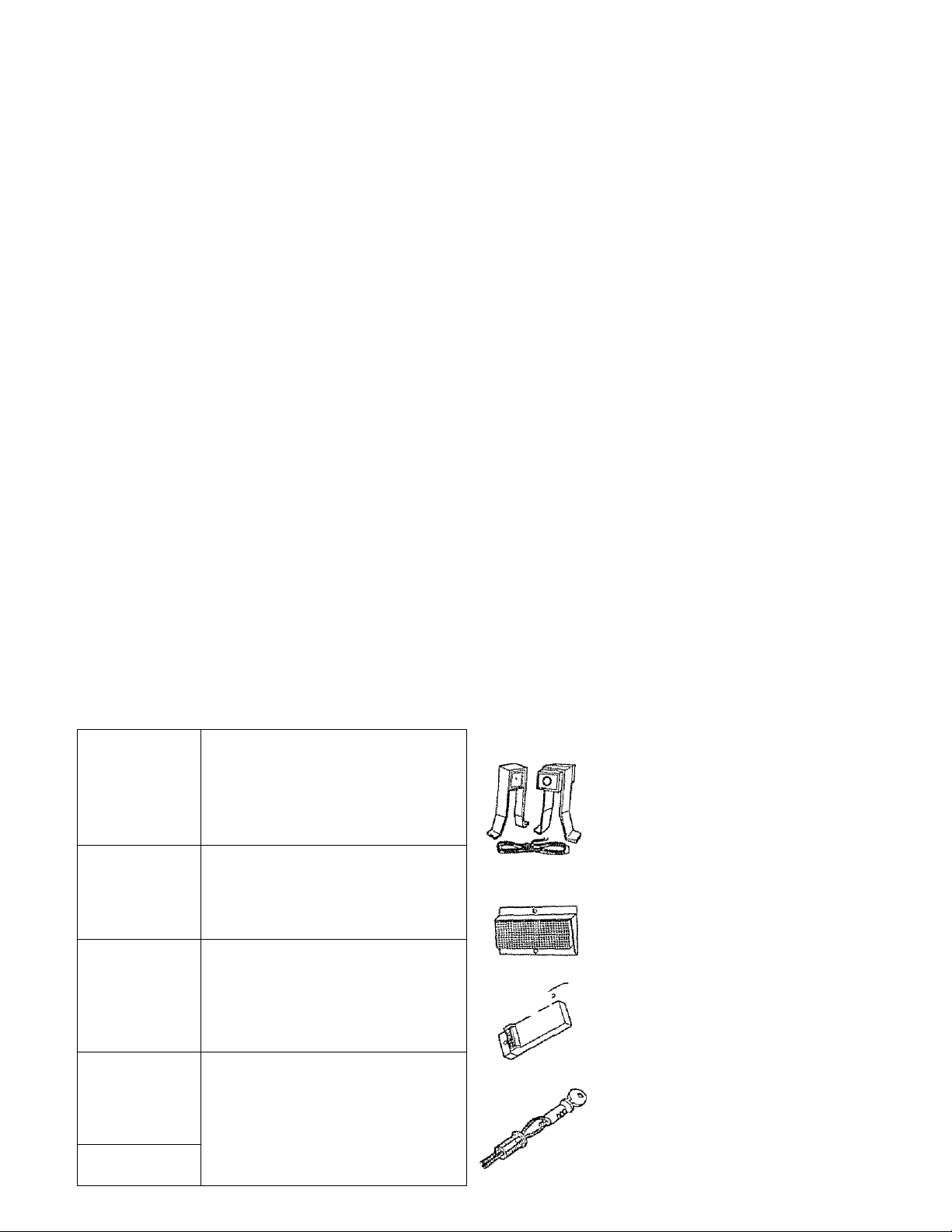
ACCESSORIES .
Sears offers many useful accessories for your garage door opener. They are illustrated below with Sears stock
numbers and descriptions.
EXTRA TRANSMITTER:
Standard size. Includes visor clip.
5375S
53703 ,
<2^
53709 DOOR CLEARANCE BRACKETS:
/ II
^ /¥ 7 , //
EXTRA TRANSMITTER:
Mini, with key ring.
OUTDOOR KEY SWITCH;
Opens the garage door automatically
from outside when transmitter is not
handy.
{For Sectional Doors Only)
Replace top brackets and rollers on
door to reduce height of door travel.
For use when instailing opener in
garage with iow headroom clearance.
0
53710
53717
53702
INFRARED REVERSING SENSOR:
An optional system which provides
auxiliary support to the safety features
buiit into your opener. If the system's
invisible beam is broken, a closing
door will reverse and an open door will
not close.
OPEN DOOR INDICATOR:
Provides an illuminated signal when
your garage door is open.
TOUCH CODE TRANSMITTER:
Enables homeowner to operate garage
door opener from outside by entering
code on specially designed keyboard.
EMERGENCY RELEASE KEYLOCK
REQUIRED for a garage with NO
service door.
Allows manual operation of garage
door from outside in case of power
failure.
Page 5
CARTON CHECK LIST
SEARS has packaged your GARAGE DOOR OPENER in two cartons which contain all the parts and hardware
illustrated below and on Page 22,
Sprodist
Covar
Rail
Groase
Transmitiera (2),
EKiepí 53415. 53315
A 53699 {1 only)
Toudi Ctxie
Transmiiter
139,53625 ONLY
Mini
Transffliaar
139 53S99 0NLY
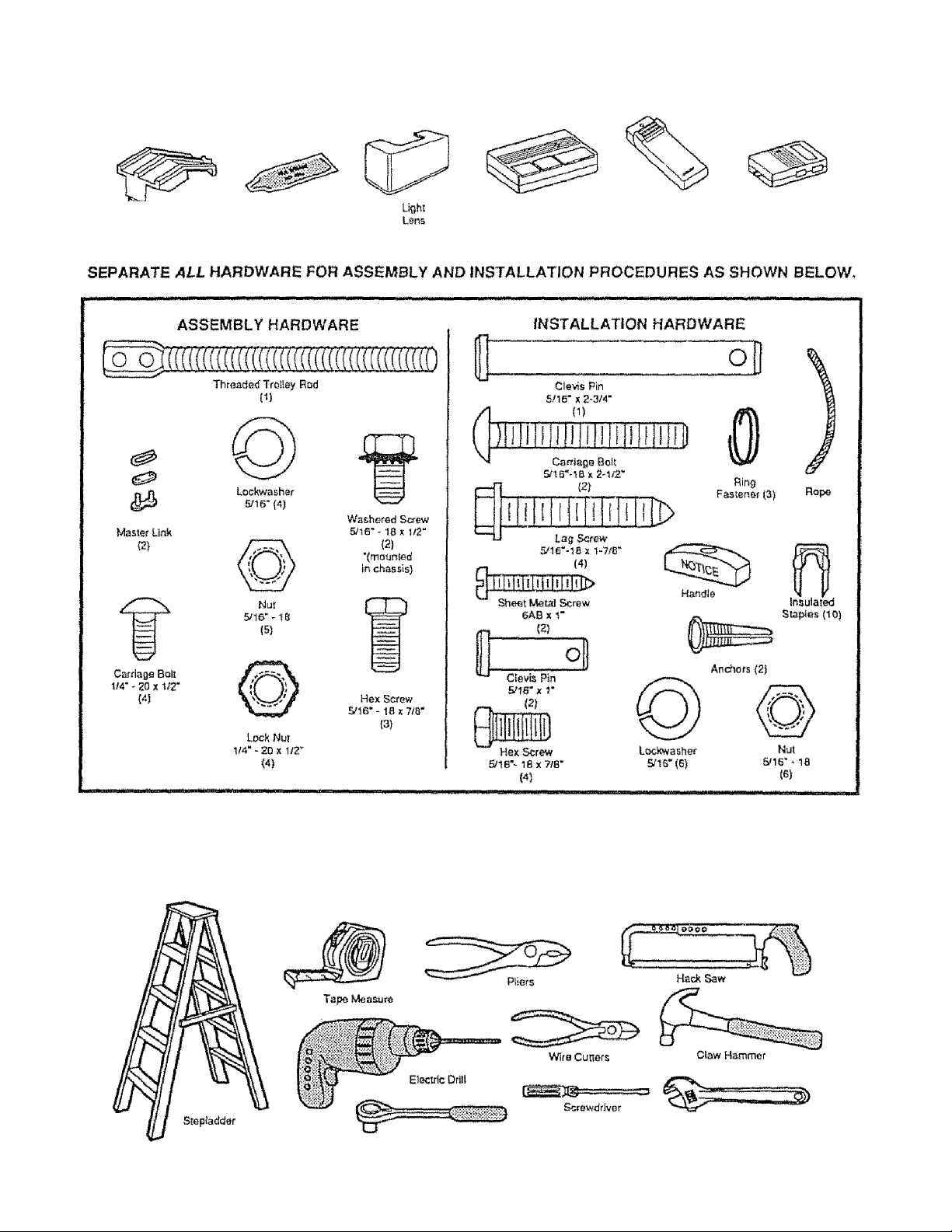
YOU’LL NEED TOOLS
During assembly and Installation of your opener, the instructions will call for the use of various hand tools. Have a
stepiadder handy, and those tools Illustrated below; hammer, electric drill {& 3/16''and 5/16"drlll bits), screwdriver,
adjustable end wrench or socket wrench kit, wire cutters, tape measure, pliers and hack saw.
Socket Wrench
Adjustable End Wrench
Page 6
Assembly
TO AVOID INSTALLATION DIFFICULTIES, DO NOT RUN THE GARAGE DOOR OPENER UNTIL INSTRUCTED TO DO SO.
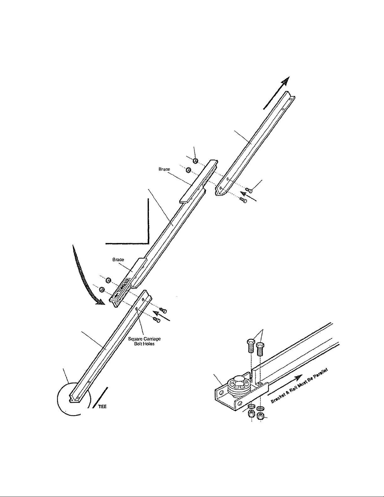
STEP 1 Assemble Tee Rail & Attach Cable Pulley Bracket
TEE RAIt BACK
{TO CHASSIS)
Tm Hai!
(Ervd Section)
CAUTION: Do not tighten the lock nuts until boll necks
are seated In square holes.
The end sections of the rail MUST be
connected to the center section from
the direction shown in the illustration.
Otherwise, the trolley will hit against
the nut when Installed (Pg. 7).
Tee Rail
(Center Section)
1M' lodi Nut
Caniage Bolt
lM*-20x1/r
PROCEDURE: Place the 3 Tee rail sections on a flat
surface for assembly THIS IS IMPORTANT. The end
sections are idenlicai.THE CENTER SECTION BRACES
MUST BE POSmONED AGAINST THE END SECTIONS
AS SHOWN. Make sure that the “directional arrow’’ls
pointing toward the front (to dcxir). Study the illustration
CAREFULLY.
(When assembled, Tee raul has afronHo-back position as
shown.)
Bolt rail sections together with the hardware illustrated and
from Ihe direction indicated.
SQUARE NECKS ON THE CARRIAGE BOLTS MUST BE
SEATED IN THE SQUARE HOLES IN RAIL SECTIONS.
Tea Rail
(End Section)
Cable pul)^ bfflckei
altadies to FRONT
END d( use ran
; RAIL FRONT
(TO DOOR)
Scfdws
&l6*-1Sx7/8'
CMite Pulley
Bracket
Lodi Washer
»16'
Nut
'S/16*
Position the cable pulley bracket on front end of tee rail
as shown. Fasten securely with the hardware provided.
IMPORTANT: When tightening screws, be sure to keep
bracket parallel to rail. Otherwise, rail may bow when
opener Is operated.
Page 7
Assembly
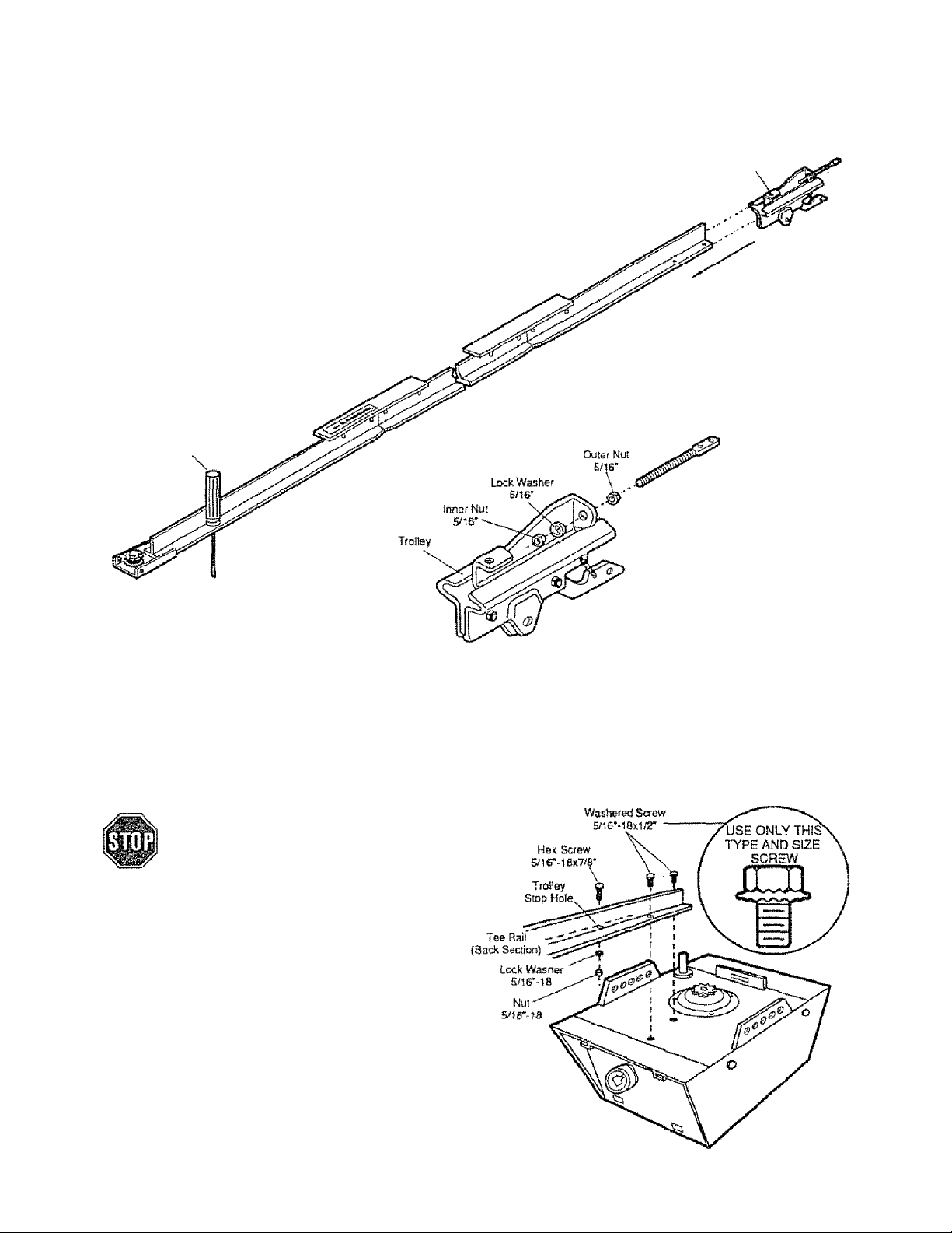
STEP 2 InstaU Trolley
AS A TEMPORARY STOP, INSERT A SCREWDRIVER
INTO HOLE IN FRONT END OF TEE RAIL AS SHOWN.
1. Attach threaded shaft to trolley with lockwasher arxJ nuts
as shown.
2. Slide trolley assembly along rail to screwdriver stop.
NOTE: if Irotley hits against the nut on Tee rail, center
section was attached from wrong side and must be
repositioned. Review Step 1.
TBtnporsry Stop
ScfBwdfivOf
\
Threadod
Shaft
TroKey
STEP 3 Attach Tee Rail To Opener Chassis
USE ONLY THOSE SCREWS MOUNTED IN
TOP OF OPENER CHASSIS. FAiLURE TO DO
SO WILL CAUSE SERIOUS DAMAGE TO THE
OPENER-
PROCEDURE; Place the opener chassis on packing
material to protect the cover. For convenience, place a
support under the cable pulley bracket.
Remove 5/16"-18 x 1/2" washered screws mounted in (op
of opener chassis. Align holes in back end of Tee rail with
holes in opener chassis. Fasten the rail to the chassis
with washered screws previously removed. CAUTION:
USE ONLY THESE SCREWS! Use of any other screws
will cause serious damage to door opener. Tighten
screws securely.
insert a 5/16"-18 x 7/8" washered screw into trolley stop
hole in the Tee rail as shown. Tighten securely with a 5/16"
lockwasher and nut.
Page 8

Assembly
DO NOT REMOVE CHAIN AND CABLE FROM CAFTTON,
Delach cable from side of carton and fasten to trolley with
a master fink from coin envelope,
MASTER LINK PROCEDURE: Push pins of master link
bar through loop of cable and hole in front end of trolley
(A) as shown. Push cap over pins and onto notches. Slide
clip-on spring over cap and onto pin notches until both pins
are locked in place.
Caation: fCeop the chain taut while instaiUng to help
prevent kinking.
With trolley against the screwdriver, dispense cable around
pulley. Proceed back around opener sprocket p)- be sure
sprocket teeth engage chain- and forward to the threaded
trolley shaft (C).
B
Opetw Chassis
Sprocket
insali Chain
(n This Direction
Use second master link to connect the chain to the flat
end of shaft as shown. Check to make sure chain Is not
twisted.
REMOVE SCREWDRIVER.
Flat End
instali Chain and Cabie
In This Direction
Master Unk
Clip-On Spring
Master Unk
Ciip-On sprine
Sprocket
Cover
Tab Skit
Mountins
Psaio
ATTACH SPROCKET COVER TO CHASSIS: insert back
IMj in chassis slot. Then bend cover forward and insert
front tab in slot provided on mounting plate-
Page 9

Assembly
STEP 5 Tight0n the Chain and Cable
Loosen
Inner
Nu!
Tmiley
:ММ1р1(МвП1МШН
Base of Tee Rail
BEFORE YOU PROCEED WITH THE INSTALLATION OF YOUR GARAGE DOOR OPENER. BE SURE TO COMPLY WITH
ALL SAFETY RULES.
KEEP GARAGE DOOR BALANCED. STICKING OR BINDING DOORS MUST BE REPAIRED. THE GARAGE DOOR,
DOOR SPRINGS, CABLES, PULLEYS, BRACKETS AND THEIR HARDWARE ARE UNDER EXTREME TENSION
AND CAN CAUSE SERIOUS PERSONAL INJURY. DO NOT ATTEMPT TO LOOSEN, MOVE OR ADJUST THEM.
CALL A GARAGE DOOR SERVICEMAN.
Lock Tighten
Washer Outer
Ь о \
Nut
Chain
....
.
1/a inch
CAUTION: Keep the chain from twisting as nuts are
turned.
PROCEDURE: Ttiread the outer nut toward trolley as
shown. (Loosen inner nut first, if necessary,)
Tension is correct when the chain is approximately 1/2"
above the base of the Tee rail, midway between pulley
bracket and chassis.
To maintain proper tension, make sure inner nut is re
tightened.
Sprocket noise can result if chain is either too loose
Of too tight.
CAUTION: Do not overtighten the chain. Defer ta
Page 3.
ASSEMBLY OF YOUR GARAGE DOOR OPENER IS NOW COMPLETE.
DO NOT WEAR WATCHES, RINGS OR LOOSE CLOTHING WHILE INSTALLING OR SERVICING A DOOR OPENER.
AS YOU PROCEED WITH THE REMAINING INSTRUCTIONS IN THIS OWNERS MANUAL, YOU MAY FIND IT HELPFUL
TO REFER TO THE FOLLOWING ILUJSTRATION OF THE FULLY ASSEMBLED AND INSTALLED GARAGE DOOR OPENER.
IT IS RECOMMENDED THAT THE OPENER BE INSTALLED 7 FEET OR MORE ABOVE FLOOR WHERE SPACE PERMITS
CERTAIN INSTALLATION PROCEDURES VARY ACCORDING TO GARAGE DOOR TYPES. WHERE THE DIFFERENCES
OCCUR, BE SURE TO FOLLOW ONLY THOSE INSTRUCTIONS WHICH APPLY TO YOUR DOOR CONSTRUCTION.
Page 10

installation
STEP 1
THE HEADER BRACKET MUST BE RIGIDLY FASTENED TO THE HEADER WALL. REINFORCE THE WALL
WITH 2x4 IF NECESSARY. FAILURE TO COMPLY MAY RESULT IN IMPROPER OPERATION OF SAFETY
REVERSE SYSTEM (SEE PAGE 18).
1. With the door dosed, locate and marK the vertical
centerline of garage door. Extend line onto header wall
atxjve the door.
2. Locale height for header bracket by opening door to
highest point of travel as shown. Draw an intersecting
horizontal line on header wall 2" above high point. This
height provides travel clearance for top edge of door.
NOTE: When the headroom is not sufficient for 2'
clearance, the bottom edge of bracket may be placed
parallel to the high point of iraveL
Door Clearance Brackets are designed for low
headroom Installations (page 4). They replace top
brackets and rollers on the garage door, thereby
lowering the high point of door travel. Installation
Instructions are contained in the accessory carton.
Hoadw
Bracicet
Installation procedures vary according to garage door types. Railow only those InsIruC'
lions which apply to your door as lilustmted.
Position and instati Header Bracket
INSTALLATION
SECTIONAL DOOR AND
1-PIECE DOOR WITH TRACK
secTraNALDOoft
CURVED TRACK
Ceiling
HORIZONTAL TRACK
ONE-PSECEDOOH
JAMB HARDWARE
Header
Bracket
tag Screws
Kigtiest
Point of
Travei
INSTALLATION
1-PlECE DOOR WITHOUT TRACK
ONE PIECE DOOR
...
NO TRACK
PIVOT HARDWARE
HiflhOEt Point
ONE PIECE DOOR
JAMB HARDWARE
Hnatffir
Bradcet
NO TRACK
\ Highest Potni
t\_ of Travtó
a. Position bracket as shown (bottom edge of bracket on
horizontal line). Mark either top and bottom or left and
right bracket holes. Drill 3/16" plot holes and fasten
bracket
1. Follow instructions as described in 1 ^ve.
2. Locate height for header bracket by opening door to
highest point of travel as shown. Measure the distance
from lop of door to floor. Subtrart actual height of door.
Add 8" to the remainder. Refer to example below,
NOTE: If total number of Inches exceeds the height
available In your garage, use the maximum height
possible. On finished ceilings, do not position the
bracket closer than 1/2" from celling.
3. Measuring from top of door draw an Intersecting
horizontal line on the header wall ^deiettnlned height.
Position the bottom edge of header bractet on the
horizorrtal line, centering bracket on vertióte line. Mark
either top ^ bottom or left and right holes. Drill 3/16*
pilot holes and fasten the bracket with 5/l6"x1-7/8* lag
screws as shown above.
EXAMPLE
Distance from top of door (at
highest point of travel) to floor
Actual height of door
Remainder .....................................................
Add
.............................................................................
Bracket height on header wail
(Measure UP from top of door
in closed position.)
....
.................
..................
......
...............
..
..
...................
—
*12"
10
Page 11

installation
STEP 3 Position Opener Chassis
<3 i«,r «3 Follow instructions which apply to your door type as illustrated.
STEP 2 Attach Tee Raff to Header Bracket
PROCEDURE: Position oponer chassis on garage floor
below the header bracket. Use packing material base to
protect cover. NOTE: To enable the Tee rail to clear
sectional door springs, it may be necessary to lift the
chassis onto a temporary support.
CMITION: Chassis must either bs secured to support
or held firmly in place by another person.
Raise the Tee rail until pulley and header brackets come
together. Align bracket holes and join with clevis pin as
shown Insert ring fastener to secure.
TO PREVENT DAMAGE TO ALL LIGHTWEIGHT DOORS AND DOORS WITH WINDOWS, DO NOT REST
HI HI THS OPENER ON THE DOOR-
INSTALLATION
SECTIONAL & ONE-PIECE
DOOR WITH TRACK
NOTE; A 2x4 is convenient for setting an ideal door*
to-Tee rail distance. It is not necessary where headroom
is insufficient.
PROCEDURE; Raise the opener chassis onto a step-
ladder, Open garage door. Place a 2x4 on top section of
door near centerilne as shown below. Rest Tee rail on 2x4,
INSTALLATION
ONE-PIECE DOOR
WITH NO TRACK
PROCEDURE: Measure the distance from floor to top of
door (in fully open position and parallel to the floor).
Using astepladder as a support, raise opener chassis to
the same distance from the floor (chassis will have a slight
angle as shown).
The top of the door should be level with the top of opener.
For maximum efficiency, do not position opener chassis
more than 2 inches above this 5>olnt.
11
Page 12

Inf^tallatîon
STEP 4 Hang Opener Chassis
THE OPENER CHASSIS MUST BE SECURELY FASTENED TO A STRUCTURAL SUPPORT OF GARAGE-
Three representative inslaliations are shown, \burs may be diffeterrt. Hanging brackets should be angled (Fig.1)
or crossed (Fig.2) to provide rigid support. On finished ceilings ^Fig.S), attach a sturdy metal bracket (not supplied) to
celling joists before installing opener.
PROCEDURE: On EACH side of the opener measure the
distance from chassis to the structural supports.
Cut both pieces of the hanging bracket to required lengths.
Ratten one end of each bracket and bend or twist to fit
the fastening angles Do not bend at the bracket holes.
Drill 3/16'' pilot holes in the structural supports. Attach flat
tened ends of brackets to supports with 5/16''xl-7/8* lag
screws.
Lift opener and fasten to hanging bracket as shown. Check
to make sure Tee rail is centered over door. REMOVE
2x4. Operate door manually. If door hits the rail, raise
header bracket.
Grease the top and underside of rail surface on
which trolley slides. A tube of grease is supplied.
RGUREl
5П6‘-18г:7/Э“ Screw
S/16" Lock Washer
5ne"-ia Nul
Bracket
(Not Supplied}
nCURES
5/16*Xl-7/8'
FiGURE 2
Lag Screws
FINISHED
CEIUNG
{No! Supplied)
&5S"-iB*7r8* Screw
Sne* Look Washer
&16*-18Nut
STEP 5 Attach Emeigency Release Rope & Handle
USE EMERGENCY RELEASE ROPE ONLY TO
DISENGAGE TROLLEY. DO NOT USE ROPE
AND HANDLE TO PULL THE DOOR OPEN OR
CLOSED,
PROCEDURE: Thread one end of rope through hole in top
of red handle so ‘NOTICE’ reads right side up as shown.
Secure with an overhand knot
NOTE: Knot should be at least Г from end of the rope
to prevent slipping.
Thread other end of rope through hole In release arm of
outer kolley. Adjust rope length so that handle is 6 feel
above the floor. Secure with an overhand knot as above.
NOTE: If it is necessary to cut rope, heat seal cut end
with a match or lighter to prevent fraying and/or
raveling.
12
Trolley
Overhand
Knot
Êmeroency
Release Handle
Page 13

Installation
STEP 6 fnstail Wall Push Button
IjDCATE wall push button (OR ANY ADDiTJONAL PUSH BUTTONS) WHERE THE GARAGE DOOR
IS VISIBLE, AWAY FROM DOOR AND DOOR HARDWARE AND OUT OF THE REACH OF CHILDREN.
SERIOUS PERSONAL INJURY FROM A MOVING GARAGE DOOR MAY RESULT FROM MISUSE OF THE
OPENER. DO NOT ALLOW CHILDREN TO OPERATE WALL PUSH BUTTON{S) OR THE TRANSMITTER.
FASTEN THE CAUTION LABEL ON THE WALL NEAR WALL PUSH BUTTON AS A REMINDER OF SAFE
OPERATING PROCEDURES,
PROCEDURE: Remove about a 1/4* of insulation from
each end of the S-strand bell wire. Connect on© end to the
screw terminals on the back of wall push button (or
doorbelt-type push button) as shown.
Fasten the wall push button with SABxl" sheet metal
screws. The doorbell-type push button has 6ABx1-l/2*
sheet metal screws. Use anchors if attaching to dry wall.
Install on an inside garage door A convenient place is be
side the service door and OUT OF REACH OF CHILDREN.
Run the bell wire up the wall and across the ceiling to the
garage door opener. Secure with insulated staples
The receiver terminals and the antenna are located on the
back panel of the opener chassis, Position antenna wire
as shown. Then connect the wire by color to the white and
red opener terminal screws.
DOOR BELL-TYPE
lighted push SUTTOW
WALL PUSH SUTTON
Pusftbutum
OPERATION OF THE VYALL PUSH BUTTON
Press and release to open or close door.
Press and releEee again to REVERSE door during
CLOSING cycle or to STOP door during OPENING
cycle.
13
Rear Panel
of Opener
WIRING INSTRUCTIONS FOR ACCESSORIES
Infrared Reversing Sensor:
To white and black opener terminals
Outdoor Key Switch:
To red and white opener terminate
-— Antenna
Page 14

JostaHation
STEP 7 InstaH Light and Lens
INSTALLING LIGHT;
Install a 75 watt maximun light bulb in socket as shown.
The light will tom on and remain lit for 4-1/2 minutes when
power is connected. After 4-1/2 minutes it will turn off.
If light bulb burns out prematurely due to vibration,
replace with a bulb specifically packaged for "Garage
Door Openers".
INSTALLING LENS:
Slide the lens Into the guides as shown Snap the bottom
t^s info fens slots.
STEP 8 Connect Electric Power
TO AVOID SERIOUS PERSONAL INJURY FROM ENTANGLEMENT, REMOVE ALL ROPES CONNECTED
TO THE GARAGE DOOR BEFORE OPERATING OPENER.
TO AVOID DAMAGE TO GARAGE DOOR AND OPENER, MAKE DOOR LOCKS INOPERATIVE BEFORE
CONNECTING ELECTRIC POWER. USE A WOOD SCREW OR NAIL TO HOLD THE LOCKS IN "OPEN”
(UNLOCKED) POSITION.
INSTALLATION & WIRING MUST BE IN COMPLIANCE WITH LOCAL ELECTRICAL AND BUILDING CODES.
OPERATION AT OTHER THAN 120V 60Hz WILL CAUSE OPENER MALFUNCTION AND DAMAGE.
Opener MUST be permanently wired or plugged into a
grounded Strong receptacle wired according to local elec
trical codes. DO NOT use a 2-wire adapter. DO NOT use ..............
an extension cord PERMANENT WIRING
CONNECTION
Ground Tab
Green Ground
Screw
RIGHT
IF LOCAL CODES REQUIRE PERMANENT WIRING:
WRONG
DISCONNECT THE POWER AT THE FUSE
BOX BEFORE PROCEEDING,
PROCEDURE: Refer to iilustration. Make connection
through the 7/8" diameter hole in top of opener chassis.
1. Remove opener chassis cover by removing the cover
screws
2. Remove attached 3-prong cord.
a Connect the black (line) wire to black wire on terminal
block; white (neutral) wire to the white terminal wire;
the green (ground) wire to green ground screw.
White
Wire'
CAUTION: BE SURE THAT THE UNIT IS GROUNDED
ACCORDING TO LOCAL CODE.
IMPORTANT NOTE: TO AVOID INSTALLATION
DIFFICULTIES, DO NOT RUN OPENER NOW.
14
Page 15

ïiisîallation
STEP
TO PREVENT DAMAGE TO LIGHTWEIGHT AND METAL GARAGE DOORS {OR ONES WITH GLASS
PANELS), ALWAYS REINFORCE THE INSIDE OF DOOR-BOTH VERTICALLY AND HORIZONTALLY—WITH
2x4 BOARDS OR ANGLE IRON.
The horizontal brace should be at least 6 feel Ion0. The vertical brace should cover height of top panel. Check
with your garage door manufacturer for a door reinforcement kit for an opener installation.
Q install Door Bracket and Plate
Follow instructions which apply to your door type as illustrated below.
Sectional Door installation Procedure
1 Assemble door bracket and plate as shown. Center
bracket on previously marked vertical guideline.
2, Position the bracket assembly on the face of the door
within the following limits;
A) The lop edge of the bracket 2"- 4* below the top
edge of the door.
B) Directly below any structura! support across the top
of the door.
Placement depends on your particular needs-
Vertical
Center
Line
Header
Bracket
One-Piece Door installation Procedure
NOTE: Door bracket has left and right aide fastening
holes. Assemble and install the door bracket and plate
if your installation requires top and bottom fastening
holes.
1, Center bracket (with or without plate as required) on
lop edge of door as shown. Mark holes.
2. Drill two 5/16" holes and fasten the door bracket with
hardware supplied
NOTE: If the door has no exposed framing, drill 3/16"
pilot holes and use 5/16* x 1 * 1/2" lag screws (not sup
plied) to fasten bracket to top of door.
NOTE: The door bracket may be installed on face of
door if required for your installation. (Refer to dotted
line drawing,) HOWEVER, drill 3/15" pilot holes and
substitute 5/16" X 1 *1/2" lag screws (not supplied) to
fasten the bracket to the door.
ONE PIECE DOOR
Header
Bracket
Door
Bra eke S
Header Wall ■
15
Page 16

Installation
C“rpp 10 Connect Door Arm to Trolley
■«j I C-r lU Follow only those instructions which apply to your door type.
Make sure garage door is closed tight. Pull the emergency release handle to disconnect the trolley. Manually move
outer trolley back to the center of inner trolley as shown In Figures A, B and C.
FIG A: Fasten straight door arm section
to outer trolley with a clevis pin Secure
the connection with a ring fastener.
Fasten curved section to door bracket in
the same way.
A
Ctevis Pin
Proceed to Step 1, page 17. Trolley will rs-engage automatically when opener is operated.
FIG B: Bring arm sections together Find
two pairs ol holes that line up and join
sections.
Select holes as far apart as possible to
increase door arm rigidity
Emergency
Reisase
Handle
N Saewa
5/ir-iax7r8"
Door Bracksi
FIG C: If holes in curved arm are ABOVE
holes in straight arm, disconnect straight
arm. Cut about 6" from the solid end.
Reconnect to trolley wilh CUT END
DOWN as shown,
Bring arm sections together Find two
pairs of holes that line up and Join with
screws, lock washers and nuts
X
Screws
S/16‘-18x7/8'
- Cut This End
ONE-PIECE DOOR INSTALLATION
SECTIONAL DOOR INSTALLATION
Door
ASSEMBLE DOOR ARM: Fasten straight and curved door
arm sections together to longest possible length. With door
closed, connect straight door arm section to door bracket
with a clevis pin. Secure with a ring fastener.
Before connecting door arm to trolley, limits of travel most be adjusted on one-piece doors. Limit adjustment screws
are located on left side panel as shown In illustralion on Page 17. Follow procedures below.
Bracket'
Clevis Pin
Straight '
Arm
5/16'-10x7/8
. Riris
Fastener
Screws
---------
Nuts
s/i6"-te
Curved
Door Arm
OPEN DOOR ADJUSTMENT
Decrease UP limit Turn UP limit adjustmenl screw counletcSockwise 4 complete turns.
Press Lighted Walt Push Button. Trolley will travel to full open.
Manually raise door arm to open position {paralSel to Itoor) and
ItIt door arm to trolley The arm should touch trolley just in back
of door arm connector hole as shown in solid line drawing. If arm
does not extend far enough, adjust limit further, One full turn
equals 2" of door travel.
CONNECT DOOR ARM TO TROLLEY; With door closed, join curved arm to connector hole in trolley with remaining clevis pin,. Secure
with ring fastening pin. NOTE: It may be necessary to lift door slightly to make connection.
Run opener through a complete travel cycie. if door has a slight ‘downward’ slant in full open position, decrease UP limits until door
is paraiiet to floor,
Decrease DOWN limit. Turn DOWN limit adjustment screw dock-
wise 8 complete turns
Press Lighted Wall Push Button. Trolley will travel to lull closed.
Manually close door and lift door arm to trolley. The arm should
touch trolley just ahead of door arm connector hoie as shown in
dolled line drawing. If arm is behind the connector hoie, adjust
limit further One lull turn equals 2" of door travel
CLOSED DOOR ADJUSTMENT
16
Page 17

Adjustment
STEP 1 Adjust UP and ÙOWN Limits
LIMIT AEJJUSTMENT settings regulate the points at which
the door will stop when moving up or down.
NOTE: Door STOPS in the UP direction if anything
interferes with door travel. Door REVERSES In fhe
DOWN direction if anything interferes with the door
travel (including binding or unbalanced doors).
PROCEDURE: To operate opener, press wall push button
or transmitter. Run the opener through a COMPLETE
TRAVEL CYCLE . Limit adjustments are not necessary
when the door opens attd closes completely and doesn't
reverse unintentionally in the down position.
The following chart outlines adjustment procedures. Run the opener through a COMPLETE TRAVEL CYCLE AFTER
EACH ADJUSTMENT. NOTE: REPEATED OPERATION OF THE OPENER DURING ADJUSTMENT PROCEDURES MAY
CAUSE MOTOR TO OVERHEAT AND SHUT OFF. SIMPLY WAIT IS MINUTES AND TRY AGAIN. Read chart carefully
before proceeding to Step 2. Use a screwdriver to make limit adjustments.
LIMIT ADJUSTMENT CHAFTT
IF DOOR DOES NOT OPEN COMPLETELY
BUT OPENS AT LEAST FIVE FEET
Increase UP travel. Turn the UP LIMIT adjustment screw
clockwise. One turn equals 2’ of travel.
If door does not open at least 5 feel: adjust OPEN
FORCE as explained in Step 2,
IF DOOR DOES NOT CLOSE COMPLETELY
(ON SECTIONAL DOORS)
increase DOWN travel.Turn down limit adjustment screw
counterclockwise. One turn equ^s 2* of travel.
If the door still wilt not close completely, fhe header bracket
is positioned too high. Repeat Step 1, page 10.
Left Side Panel
IF DOOR DOES NOT CLOSE COMPLETELY
(ON ONE-PIECE DOORS)
Increase DOWN travel. Turn the down limit adjustment
screw counterclockwise. One turn equals 2" of travel,
IF DOOR REVERSES WHEN CLOSING AND THERE
IS NO INTERFERENCE TO TRAVEL CYCLE
Test door for binding: Pull emergency release handle.
Manually open and close door. If door is binding, call a
door serviceman, If door is not bindirvg or unbalanced,
adjust CLOSE FORCE, See Step 2.
IF OPENER REVERSES IN FULLY CLOSED POSITION
Decrease DOWN travel Turn down limit adjustment screw
clockwise. One turn equals 2" of travel.
WC^EASe iWCfiÊASE,
iXîWH UP Ç
(®
TftAVCi IRAVEt
Adjustment Label
STEP 2 Adjust Force
DO NOT USE FORCE ADJUSTMENTS TO COMPENSATE FOR A BINDING OR STICKING GARAGE DOOR,
EXCESSIVE FORCE WILL INTERFERE WITH PROPER OPERATION OF SAFETY REVERSE SYSTEM OR
DAMAGE GARAGE DOOR.
Force Adjustment Controls are located on rear panel of
opener. FORCE ADJUSTMENT settings regulate amount
of the power required to open and close door.
NOTE: The door STOPS In the UP dlrectiot» if attyfhing
Interferes with Its travel. Door REVERSES In the DOWN
direction if anything interferes with Its travel (ihciuding
binding or unbalanced doors).
If the force Etejusfments are set too light, door tra\rel may be
interrupted by nuisance reversals in DOWN direction and
stops in UP direction. As weather conditions can affect the
door movement, occasional adjustment may be needed.
Maximum force adjustment range is 260 degrees, about
3/4 of a complete turn. Do not force controls beyond that
point. Turn force adjustment controls with a screwdriver.
FORCE ADJUSTMENT CHART
TEST DOWN (CLOSE) FORCE
Grasp the door hmtils or door bottom when door is about
halfway through DOWN (CLOSE) TRAVEL. Door should
retterse. If the door Is hard to hold or doesn’t reverse,
decrease DOWN (CLOSE) FORCE by lurntng (he control
in a counterclockwise direction. 10 degree turn
adjustments until door reverses normally. After each
adjustment, run opener through a complete cycle.
PROCEED TO STEP 3
Back Panel
ol Opener
Fort»
Adjustment
^ Control
Adjustment Label
IF DOOR DOESN’T OPEN AT LEAST 5 FEET
Increase UP (OPEN) FORCE by turning control clockwise.
Make 10 degree turn adjustments until door opens
completely. Readjust UP LIMIT if necessary. After each
adjustment, run opener through a complete travel cycle.
IF DOOR REVERSES DURING DOWN (CLOSE) CYCLE
Increase DOWN (CLOSE) FORCE by turning the control
clockwise. Make 10 degree turn adjustments until door
completes close cycle. After each adjustment, run the
opener through a complete travel cycle.
17
Page 18

Adjusiment
STEP 3 Test Safety Reverse Sysiem
THE SAFETY REVERSE SYSTEM TEST iS IMPORTANT. GARAGE DOOR MUST REVERSE ON CONTACT
WITH A ONE INCH OBSTACLE PLACED ON THE FLOOR. FAILURE TO PROPERLY ADJUST OPENER MAY
RESULT IN SERIOUS PERSONAL INJURY FROM A CLOSING GARAGE DOOR. REPEAT TEST AT LEAST
FOUR TIMES A YEAR AND ADJUST AS NEEDED.
PROCEDURE: Place a 1-irtch obslacie on the floor under
the garage dcMsr. Operate door in DOWN direction. The
door MUST reverse on the obstruction.
If the door STOPS on the obstruction, it is not traveling
far enough in the DOWN direction. Increase the DOWN
limit by turning DOWN limit adjustment screw counter
clockwise 1/4 turn. REPEAT TEST.
NOTE; Make sure limit adjustments do not force the
door arm beyond a straight up and down position. See
the illustration on Page 16.
When the door rsvetses on the 1-inch obstacle, remove
the obstruction and tun the opener through a complete
travel cycle. Door MUST NOT reverse in closed position.
If it does, repeal Adjustment Steps 1, 2 and 3,
REPEAT ADJUSTMENT STEP 3 AFTER:
® EACH AiWUSTMENT OF DOOR ARM LENGTH, CLOSE FORCE OR DOWN LIMIT.
ANY REPAIR OR ADJUSTMENT OF GARAGE DOOR (INCLUDING SPRINGS AND HARDWARE).
ANY REPAIR OR BUCKLING OF THE GARAGE FLOORANY REPAIR OR ADJUSTMENT OF THE GARAGE DOOR OPENER.
(Optional) STEP 4 Install Infrared Reversing Sensor
The iNFRAREO REVERSING SENSOR provides an
ADDITIONAL measure of safety against a small child
being caughi under a garage door. It uses an invisible
beam which, when broken by an obstruction, causes a
closing door to open and prevents an open door from
closing. ■
Mer the garage door opener has been completely instaitecJ
and adjusted, the INFRARED REVERSING SENSOR
accessory can be installed. Inslmctions are included with
this optional device.
18
^4 V IS
fcaati Immm
Page 19

Radio Controls
F.C.C rules prohibit adjustments to or modification of receiver and transmitter circuitry except for changing the
code setting and repfacing the transmitter battery THERE ARE NO OTHER USER SERVICEABLE PARTS
Your 53000SR SERIES garage door opener (with RECEIVER *SR’ CODE BUTTON) has been factory set to operate
with the LARGE push builort on the transmitter. The 3-function transmilter(s) can also activate additional garage
door openers and/or light controls • S3000 and/or 53000SR SERIES,
Instructions are given below for matching the code in all transmitters, changing your code selection or using the
transmitter(s) with other receivers,
1. Locate the code switches in transmitlerfs), either by sliding battery compartment cover down or by removing cover
screw and carefully turning case top over
2. With a pen or a screwdriver, change the setting of one or more switch (to a (+), (-) or (0) position).
NOTE; Code switches 2 through 9 in ALL transmitters used to operate a receiver must be set to match. (Code
switch 1 on a 3-funct(on transmitter is neutral, Set it to ANY position. It wHi not affect the code selected).
Manyfactured under 1 or more ol the tolSowirtg US, patenis: HE29325: 4,037,201; 4.750,110; 4,008,930
MATCH/CHANGE THE CODE IN TRANSMITTER(S)
SET CODE SWITCHES IN ALL TRANSMITTERS TO MATCHING POSITIONS
Standard
' 3'Füficílon
Transmitter
“Code Switches
11.9)
Standard
3*Funciion
Trans mitler
i—Cod© Swjldies
(2-9)
1^' tj
3-Funafen
' Mini TransmitSer
- Cocfe SwiKhes
(1-0)
SET RECEIVER TO ftflATCH TRANSMITTER(S) CODE
53000SR SERIES (WITH RECEIVER CODE BUTTON)
Garage Door Openers and Light Conlrois
(IHustratton A shows a garage door opener receiver)
3 FUNCTION
TRANSMÍTTER
Select a iransminer push
bunon 10 opsraie racskíer
\
I'
\ ■
A
SR Indicator
Code Btmort Light
GAHAGE DOOR
OPENER fiECetVER
(Wilh SR Code Button)
WfT SLK V
3. Press the RECEIVER SR code button on the right side
panel of opener (lilustralion A) The indicator light will
turn ON.
4, STAND AWAY FROM THE DOOR and press the
selected push button on the transmitter. The indicator
tight win turn OFF and door will move. Receiver and
transmitter codes now match and the opener will
operate with the selected push button on the transmitter.
NOTE: If transmitter push button is not pressed
within 30 seconds, the indicator light wilt turn OFF.
Begin again at Step 3.
TO USE THE TRANSMITTER(S) WITH OTHER 53000SR
SERIES RECEIVERS; Select another transmitter push
button to operate the Light Control or additional garage
door opener. Make sure all transmitters used to operate
receiver are set to the same code (Steps 1 and 2) Repeat
Steps 3 and 4.
S3000 SERIES (WITH RECEIVER CODE SWITCHES)
Garage Door Openers and Light Controls
{Illustration B shows a garage door opener receiver)
Push Button (-)
Push Button <+5
Code Switch #1 (-)
Receiver wilt operate
with trafismilters'
large push bunon
3 FUNCTION
TRANSMITTER
Select a trarssminer
push button to operate
receiver
GARAGE DOOH
OPENER RECEIVER
(With Code Switches)
Slide receiver code
switch SI !o position
that matches ssSected
transmitter push bunon
(+) S or-)
3, Locate the receiver code switches. Set code switch #1
to matcli transmitter push button you want to use with
that receiver (+), (0) or (-). Refer to iSiustratlon (B),
4. Hold a transmitter (with code switches visible) along
side the receiver. Beginning with RECEIVER code
switch #2, match the position of each transmitter
switch.
TO USE THE TRANSMITTER(S) WITH OTHER 53000
SERIES RECEIVERS: Select another transmitter push
button to operate the Light Control or additional garage
door opener.. Make sure all transmitters are set to a match
ing code (Steps 1 and 2), Repeat Steps 3 and 4
19
Page 20

Having a Problem? F^evtew Pages 2 and 3 Before Proceeding
SITUATION
OPENER DOESN’T OPERATE
FROM EITHER THE WALL PUSH
BUTTON OR TRANSMITTER
OPENER OPERATES FROM
TRANSMITTER BUT NOT
FROM WALL PUSH BUTTON
DOOR OPERATES FROM
WALL PUSH BUTTON BUT NOT
FROM THE TRANSMITTER
PROBABLE CAUSE & SOLUTION
1 Have you disengaged all door locks? Review Step 8, page 14,
2, Does the opener have electric power? Plug a lamp Into the outlet. If it doesn’t
light, check fuse box or circuit breaker (Some outlets are controlled by a wall switch.}
3 Repeated operation may have tripped the overload protector in the motor Wait
15 minutes. Try again.
4. Is there a build-up of ice or snow under door? Door may be frozen to ground. Re
move any obstruction,
5, Remove bell wire from opener terminals. Short red and white terminals by touch
ing both terminals at same time with a piece of metal (screwdriver or coin). If operver
runs, check for a faulty wire connection at wall push button or a short under staples.
1 Is w/all push button lit? If not. refer to No, 5 above and follow same procedure.
2 Are wiring connections correct? Review Step 6. page 13
Does the battery test light glow when transmitter push button is pressed? If not,
replace the battery
If you have two transmitters and only one operates, review the code setting
procedures on page 19. ALL transmitters must be set to same code.
Is transmitter(s) operating any other remote control devices? See the code setting
procedures on page 19,
Did you press the transmitter button designated to operate garage door opener?
Reprogram receiver and ALL transmitters, Try setting ALL transmitter code switches
on plus, center or minus positions. If transmitter(s) works, you can try a random
code switch setting again, if you desire.
TRANSMITTER HAS
SHORT RANGE
THE GARAGE DOOR OPENS
AND CLOSES BY ITSELF
DOOR DOESN’T OPEN
COMPLETELY
DOOR DOESN’T CLOSE
COMPLETELY
1 Check battery test light If the light is dim, change the battery
2. Change the location of the transmitter in the car.
3 A metal garage door or foil-backed insulation or metal siding will reduce the
transmission range Antenna extender kit is available from any Sears Store or
Service Center
4 Check to be sure antenna on the back panel of opener extends fully downward.
1
Is there a neighbor with a garage door opener using the same frequency code?
Change your code Review page 19
Check to be sure that none of the transmitter push buttons is stuck in the ‘down’
2.
position-.
Remove belf wire from opener terminals and operate from transmitter only. If this
solves the problem, the wall push button is faulty (replace), or there is a short or
broken wire between push button and opener.
Is something obstructing the door?
if door opens at least 5 feet, travel limits may need to be increased. One turn equals
2 inches of travel. See page 17.
REPEAT SAFETY REVERSE TEST after the adjustment is complete.
If door has been working properly but now doesn't open all the way, increase the
UP FORCE. See page 17.
REPEAT SAFETY REVERSE TEST after the adjustment is complete.
1. Is something obstructing the door?
2. Review the Travel Limits Adjustment Chart on page 17.
REPEAT SAFETY REVERSE TEST after any adjustment of door arm length,
close force or down limit.
DOOR WON’T CLOSE
1, The Infrared Reversing Sensor (If you have installed this accessory) may
misaligned or obstructed. Disconnect sensor and check door operation, f
problem disappears, correct alignment
20
Page 21

Having a Problem? (continued)
SITUATION
DOOR REVERSES FOR
NO APPARENT REASON
OPENER LIGHT
PROBABLE CAUSE & SOLUTION
1. is something obstructing the door? Pul! red emergency releas handle Operate
door manualiy If if is unbalanced or binding, call a garage door servicerrian to
correct the problem,
2. Clear any ice or snow from garage floor area where garage door doses
3. Review the Force Adjustment Chart on page 17
REPEAT SAFETY REVERSE TEST after adjustment is complete,
4. If door reverses in FULLY CLOSED position, decrease travel limits (see page 17)
REPEAT SAFETY REVERSE TEST after the adjustment is complete.
THE need FOR OCCASIONAL ADJUSTMENT OF THE FORCE AND LIMIT
SETTINGS IS NORMAL. WEATHER CONDITIONS IN PARTICULAR CAN
AFFECT DOOR TRAVEL.
5. The infrared Reversing Sensor (If you have installed this accessory) may be
misaligned or obstructed. Disconnect sensor and check door operation tf problem
disappears, correct alignment.
DOESN’T TURN ON
1, Replace the light bulb (75 watts maximum) Use a "garage door opener bulb" if
standard buib burns out prematurely due to vibration Vibration may be caused
by loose end panel. Retighten screws.
DOESN’T TURN OFF
1, There may be a defective ground at ceiling or wall receptacle
UNIT MUST BE GROUNDED.
OPENER STRAINS OR
MAXIMUM FORGE IS NEEDED
TO OPERATE DOOR
OPENER MOTOR HUMS
BRIEFLY, THEN WON’T WORK
OPENER WON’T OPERATE
DUE TO POWER FAILURE
CHAIN DROOPS OR SAGS
1. Door may be out of balance or springs are broken, Close doorand use emergency
release rope and handle to disconnect trolley. Open and close door fnajiualiy A
properly balanced door will stay in any point of travel while being supported entirely
by Its springs. If it does not, call a garage door serviceman to correct the problem.
1. Garage door springs are broken, SEE ABOVE
2. The trolley may be jammed into stop bolts, Pull or push on door while motor is
humming to release jammed condition. Re-adjust door limits (page 17) to prevent
over-travel.
REPEAT SAFETY REVERSE TEST after adjustment is complete.
3. if the problem occurs on first operation of the opener, door is iock^sd DISABLE
DOOR LOCK. If chain was removed and reinstalled, motor may be out of phase
Remove chain; cycle motor to the down position (Observe drive sprocket When
it turns in clockwise direction and stops in down position.) Reinstall chain.
REPEAT SAFETY REVERSE TEST after adjustment is complete.
1. Use emergency release rope and handle to disconnect trolley Door can be opened
and dosed manually. When the power is restored, press the wall push button and
trolley will automatically reconnect Refer to Page 3 for Lockout Feature
2. The emergency release Key Lock accessory (for use on garages with no service
door) disconnects the trolley from outside the garage in case of power failure.
1. it is normal for chain to droop slightly in the closed door position. Use emergency
release rope and handle to disconnect trolley. If chain returns to normal height
when the trolley is disengaged and door reverses on a one-inch obstruction, no
adjustments are needed (see page 9)
OPENER NOISE IS DISTURBING
IN LIVING QUARTERS OF HOME
1. If operational noise is a problem because of proximity of the opener to the living
quarters, Vibration isolator Kit 41A3263 can be ordered from any Sears Service
Center and most Sears stores This kit was designed to eliminate the 'sounding
board effect' and is easy to install.
21
Page 22

Repair Parts
RAIL ASSEMBLY PARTS LIST
KEY
PART
NO.
NO.
1
1A995 Master link kit
2
41S3244
3
41B3243 Inner trolley
4
2B313 Tee rail-center section
5 183B93
6 41B2616
7
41A3473 CHsin and
41A3534
DESCRIPTION
Outer trolley
Tee rail-end section (each)
Cable pulley bracket assy
NOT SHOWN
Rail assy hardware kit (includes
hardware illustrated on page 5)
INSTALLATION PARTS LIST
3-a
KEY
NO.
a. 1 41A3472-1 Wall push button assy
to
11 178B35 Curved door arm section
12 178B34
13 12B350
PART
NO. description
2 41A2756
10A14
3
4 41A3476
5 29C128 Transmitter visor dip
41A2B28
6
7 219A323 2-strand bell wire
41A2829 Header bracket w/cle vis pi n & fastener
8
12B374
9
12B380 Door bracket piaie
41A3S35 installation hardware bag (includes
444A443&* Owners manuaJ
Doorbeli-type lighted push button
12V battery
Transmitter case, cover & screw assy.
Emergency rope & handle assy.
Door bracket
Straight door arm section
Hanging brackets
NOT SHOWN
hardware illustrated on page 5)
n4-ftl,din
Ly
22
 Loading...