

Craftsman 139.53610, 139.53413, 139.53606 Owner's Manual
00000
OD
139
1
139°53606
139.5361 0
- 1/3HP
- 1/2 HP
= 1/2 HP
° 1/3 HP
Owners Manual
CAUTION
READ INSTRUCTIONS AND RULES
FOR SAFE OPERATION CAREFULLY
CONTENTS PAGE
Features of Your Opener ............. 2
Specifications .......................... 2
Accessories ............................... 2
Carton Check List ...................... 3
You'll Need Tools .................... 3
Safety Rules .............................. 4
Operation of Your Opener ............ 5
Maintenance Schedule ............... 5
Assembly .................................. 6
Installation Information ................. 9
Installation ........................... 9
Force& Limit Adjustment ............ 17
Safety Reverse Test ...................... 18
Setting/Changing Code ................ 19
Having a Problem? ..................... 20
Repair Parts, Rail Assembly ........... 22
Repair Parts, Installation .............. 22
Repair Parts, Chassis Assembly ..... 23
How to Order Repair Parts ........... 24
Maintenance Agreements ........... 24
Sears Warranty ......................... 24
FASTEN OWNERS MANUAL NEAR GARAGE DOOR AFTER INSTALLATION IS COMPLETE.
PERIODIC CHECKS OF THE OPENER ARE REQUIRED TO INSURE SATISFACTORY OPERATION.
FEATURES OF YOUR OPENER
1. Motor: Permanently lubricated with automatic
reset,
2. Opener Light: Turns on and off automatically.
Provides 4-1/2 minute illumination for your safety
and convenience,
3. Safety System: Independent up and down force
adjustment. Door reverses automatically when
obstructed in DOWN direction Door STOPS when
obstructed in UP direction
4. EasyLimitAdjustment: Limitsofdooropening
and closing adjusted by turning screws without
removing chassis cover
5. Digital Radio Controls: The code can be easily
changed by the owner
6. 3_Channel Transmitter: Three push buttons,
Each button can activate one or more remote
control devices The large transmitter button is
factory preset to operate the garage door opene_
7. Emergency Disconnect: Pullcord disconnect
permits manual door operation,
8. Automatic Reconnect: The trolley halves re-
connect for automatic operation when opener is
energized after emergency disconnect
SPECIFICATIONS
MOTOR SAFETY
Type . Permanent split capacitor
Speed 1500 rpm
Vofts .... 120 Volts AC - 60 Hz Only
Current 45 amperes
DRIVE MECHANISM
Gears ..... 16:1 worm gear reduction
Drive Chain & cable with two*piece trolley on
steel Tee rail
Length of Travel Adjustable to 7-1/2 feet
Travel rate 6 to 8 inches per second
Lamp .... On when door starts in travel, off 4-1/2
minutes after stop
Door linkage Adjustable door arm Pug cord troUey
release
Personal .... Push button & automatic reversal in down
direction Push button & automatic stop
tn up direction
Electronic Independent up & down force adjustment
screws
Electrical Motor overload protector and low voltage
push button wiring
Limit device . Circuit actuated by limit nut
Limit adjustment Screwdriver adjustment on side panel
Start circuil Low voltage push button or radio control
DIMENSIONS
Length (overall) . 124 in
Headroom required 2 inches
Hanging Weight 32 pounds
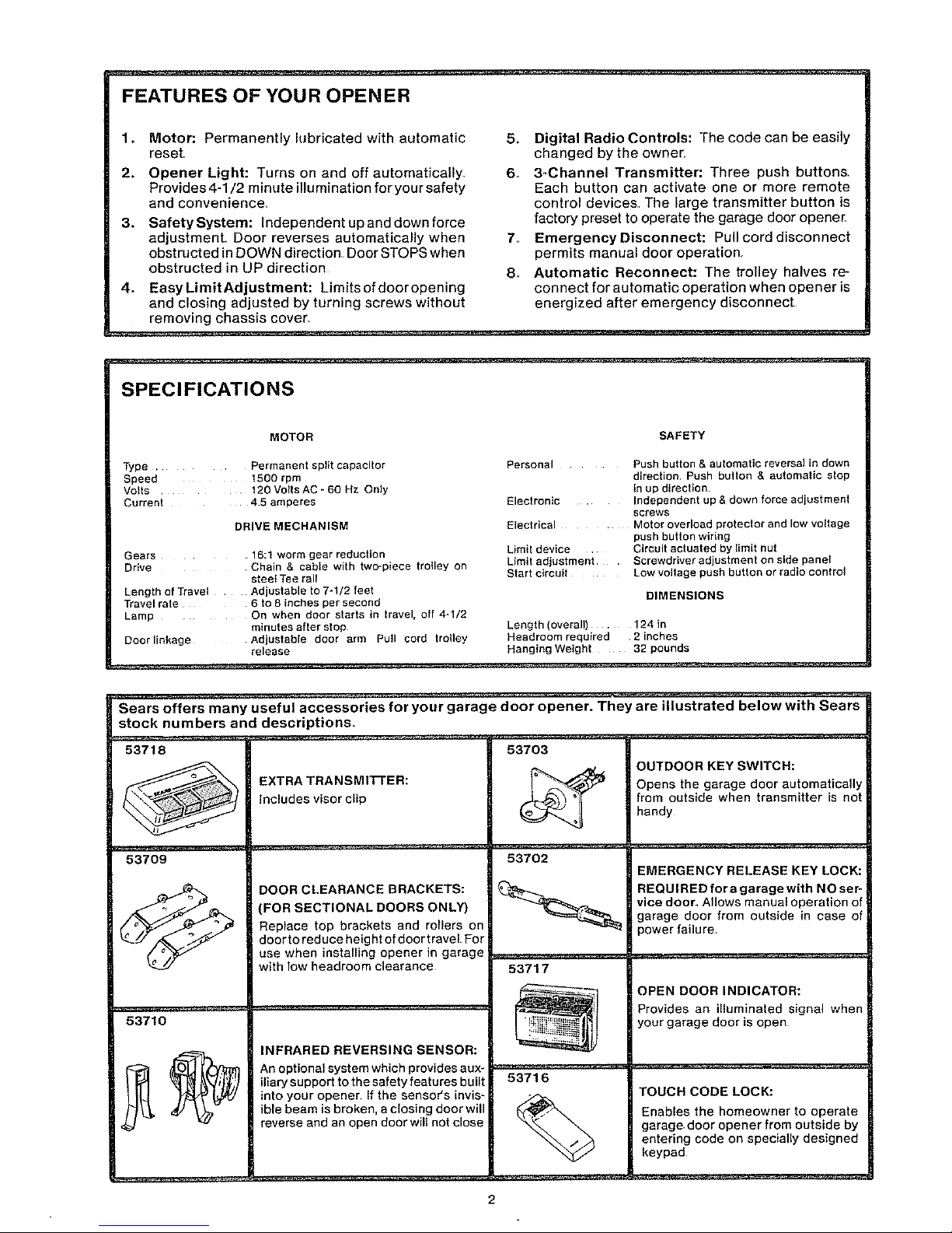
Sears offers many useful accessories for your garage door opener. They are illustrated below with Sears
stock numbers and descriptions,
53718 53703
OUTDOOR KEY SWITCH:
EXTRA TRANSMITTER: Opens he garage doer automat ca ly
Includes visor clip from outside when transmitter is not
handy
53709 53702
EMERGENCY RELEASE KEY LOCK:
_/_ DOOR CLEARANCE BRACKETS: REQUIRED fora garage with NO set-
(FOR SECTIONAL DOORS ONLY} vice door° Allows manual operation of
garage door from outside in ease of
Replace top brackets and rollers on power failure
doorto reduce height of door travel For
use when installing opener in garage ......................................................................................
with low headroom clearance 53717
......_-7 OPEN DOOR INDICATOR:
Provides an illuminated signal when i
• !_ your garage door is open
53710 . ._ii_E_.._
INFRARED REVERSING SENSOR:
"_ t_'. I_l'Ybzm An optional system which provides aux ...........................................................................................
iliary support to the safety features built 53716
into your opener If the sensor's invis- _ TOUCH CODE LOCK:
ible beam is broken, a closing door will _ Enables the homeowner to operate
reverse and an open door will not close garage door opener from outside by
entering code on specially designed
keypad
2
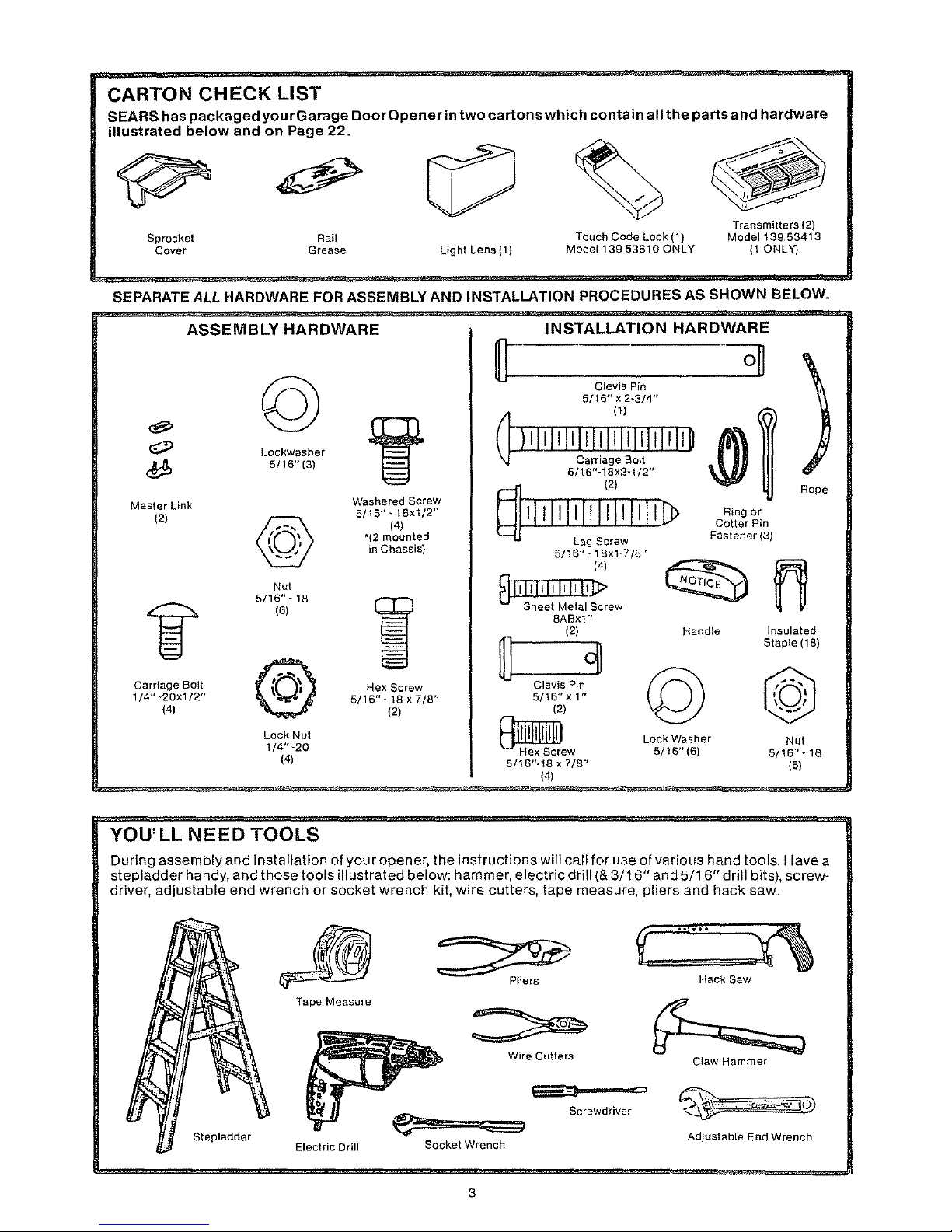
CARTON CHECK LIST
SEARS has packaged yourGarage Door Opener in two cartons which contain all the parts and hardware
illustrated below and on Page 22.
Light Lens (1)
Transmitters {2)
Sprocket Rail Touch Code Lock (1) Model 13953413
Cover Grease Model 139 53610 ONLY (1 ONLY)
SEPARATE ALL HARDWARE FOR ASSEMBLY AND INSTALLATION PROCEDURES AS SHOWN BELOW.
ASSEMBLY HARDWARE INSTALLATION HARDWARE
Lockwasher
(_ 5116"(3)
Master Link
(2)
Washered Screw
5/16"- 18xl/2'"
(41
*(2 mounted
in Chassis)
Nut
5/16 "_ 18
(B)
Carriage Bolt _f _ Hex Screw
1/4''_20xl/2" _ 5/16"-18x7/8"
(4) (2)
Lock Nut
1/4" -20
(4)
Clevis Pin
5/16" x 2-3/4"
5116"-18x2-1/2"
5!16" - 18xl-7/8"'
(4)
8ABxl '
(2) Handle
Clevis Pin
5/16" x 1"
(2)
_re Lock Washer
w 5/15"(6)
5/16"-18 × 7/8"
(4)
Ring or
Cotter Pin
Fastener(3)
Insulated
Staple (18)
©
Nut
5/16"-18
(6)
YOU'LL NEED TOOLS
During assembly and installation of you ropener, the instructions willcall for use of various hand tools,Have a
stepladder handy, and those tools illustrated below: hammer, electric drill (& 3/1 6" and 5/1 6" drill bits), screw-
driver, adjustable end wrench or socket wrench kit, wire cutters, tape measure, pliers and hack saw
Stepladder
Tape Measure
Electric Drill
Pliers
Hack Saw
Wire Cutters
Screwdriver
Socket Wrench
Claw Hammer
Adiustable End Wrench
3

Start By Reading These Impo ant Safety Rules
THIS SAFETY ALERT SYMBOL MEANS CAUTION -- PERSONAL SAFETY OR PROPERTY
DAMAGE INSTRUCTION. READ THESE INSTRUCTIONS CAREFULLY°
THIS GARAGE DOOR OPENER IS DESIGNED AND TESTED TO OFFER REASONABLY
SAFE SERVICE PROVIDED IT IS INSTALLED AND OPERATED IN STRICT ACCORDANCE
WITH TH E FOLLOWING SAFETY INSTRUCTIONS.
FAILURE TO COMPLYWITH THE FOLLOWING INSTRUCTIONS MAY RESULTIN SERIOUS
PERSONAL INJURY OR PROPERTY DAMAGE,
CAUTION: IF YOUR GARAGE HAS NO SERVICE ENTRANCE DOOR, INSTALL MODEL 53702 EMERGENCY RELEASE
KEYLOCK (PAGE 2). THIS ACCESSORY ALLOWS MANUAL OPERATION OF GARAGE DOOR FROM OUTSIDE IN CASE OF
POWER FAILURE.
KEEP GARAGE DOOR BALANCED° Sticking or
binding doors must be repaired.. Garage doors,
door springs, cables, pulleys, brackets and their
hardware may be under extreme tension and can
cause serious personal injury. DO NOT ATTEMPT
ADJUSTMENTS. Call a garage door seP_iceman
to move or adjust door springs or hardware_
DO NOT USE FORCE ADJUSTMENTS TO COM-
PENSATE FOR A BINDING OR STICKING
GARAGE DOOR. Excessive force will Interfere
with the proper operation of the safety reverse
system or damage the garage door° (Page 17)..
DO NOT WEAR RINGS, WATCHES OR LOOSE
CLOTH ING while installing or servicing a garage
door opener.
Fasten the CAUTION LABEL on the wall nearthe
lighted wall control as a reminderof safe operating
procedures.
To avoid serious personal injury from entangle-
ment, REMOVE ALL ROPES CONNECTED TO
THE GARAGE DOOR before installing the garage
door opener.
DISENGAGE ALL EXISTING GARAGE DOOR
LOCKS to avoid damage to garage door,,
Installwallcontrol(or additional push buttons) IN
A LOCATION WHERE GARAGE DOOR ISVISIBLE,
BUT OUT OF THE REACH OF CHILDREN. DO
NOTALLOWCHILDREN TOOPERATETHEWALL
PUSH BUTTON(S) OR TRANSMITTER. Serious
personal injury from a closing garage door may
result from misuse of opener..
Installation and wiring must be in compliance
with your local building and electrical codes.
CONNECT POWER CORD ONLYTO A PROPERLY
GROUNDED OUTLET.
CAUTION: Activate opener onlywhen the door is in
fu IIview, free of obstm ctio n an d opener is properly
adjusted° NO ONE SHOULD ENTER OR LEAVE
THE GARAGE WHILE DOOR IS IN MOTION° DO
NOT ALLOW CHILDREN TO PLAY NEAR DOOR°
LIGHTWEIGHT FIBERGLASS, ALUMINUM AND
STEEL DOORS MUST BE SUBSTANTIALLY RE-
INFORCED TO AVOID DOOR DAMAGE. (See
page 15.) The best solution is to check with you r
garage door manufacturer for an opener installa o
tion reinforcement kit_
Use emergency release ONLY to disengage trolley
and, if possible, ON LY when the door is closed.
DO NOT USE RED EMERGENCY RELEASE ROPE
AND HANDLE TO PULL DOOR OPEN OR CLOSED
THE SAFETY REVERSE SYSTEM TEST IS IM*
PORTANT. (See Pg.18). Your garage door MUST
reverse on contact with a one*inch obstacle placed
on the floor_ Failure to properly adjust the opener
may result in serious personal injury from a closing
garage door., REPEAT TEST AT LEAST ONCE
EVERY THREE MONTHS AND MAKE NEEDED
ADJ USTMENTS_
_ DISCONNECT ELECTRIC POWER TO GARAGE
DOOR OPENER BEFORE MAKING REPAIRS OR
REMOVING COVERS..
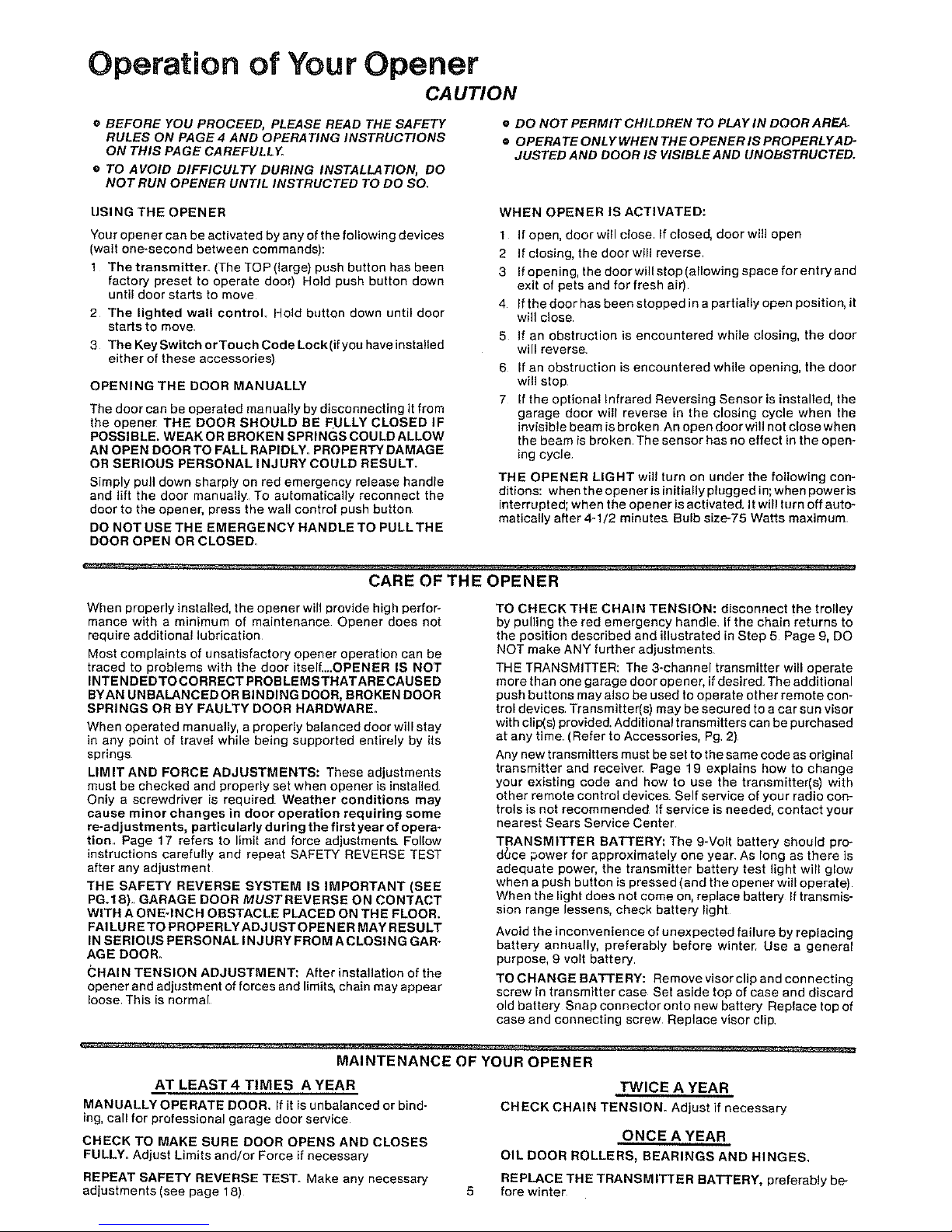
Operation of Your Opener
CAUTION
e BEFORE YOU PROCEED, PLEASE READ THE SAFETY
RULES ON PAGE 4 AND OPERATING INSTRUCTIONS
ON THIS PAGE CAREFULLY.
e TO AVOID DIFFICULTY DURING INSTALLATION, DO
NOT RUN OPENER UNTIL INSTRUCTED TO DO SO.
• DO NOT PERMIT CHILDREN TO PLAY IN DOOR AREA.
• OPERATEONLYWHENTHEOPENERISPROPERLYAD-
JUSTED AND DOOR IS WSIBLE AND UNOBSTRUCTED.
IJSING THE OPENER
Your opener can be activated by any of the following devices
(wait one-second between commands):
1 The transmitter. (The TOP (large) push button has been
factory preset to operate door) Hold push button down
until door starts to move
2 The lighted wall control, Hold button down until door
starts to move
3 The KeySwitch orTouch Code Lock(if you have installed
either of these accessories)
OPENING THE DOOR MANUALLY
The door can be operated manually by disconnecting it from
the opener THE DOOR SHOULD BE FULLY CLOSED IF
POSSIBLE, WEAK OR BROKEN SPRINGS COULD ALLOW
AN OPEN DOOR TO FALL RAPIDLY. PROPERTY DAMAGE
OR SERIOUS PERSONAL INJURY COULD RESULT.
Simply pull down sharply on red emergency release handle
and lift the door manually To automatically reconnect the
door to the opener, press the wall control push button
DO NOT USE THE EMERGENCY HANDLE TO PULLTHE
DOOR OPEN OR CLOSED
WHEN OPENER IS ACTIVATED:
I If open, door will close if closed, door will open
2 If closing, the door will reverse
3 If opening, the door will stop (allowing space for entry and
exit of pets and for fresh air)
4 If the door has been stopped in a partially open position, it
will close
5 If an obstruction is encountered while closing, the door
will reverse
6 If an obstruction is encountered while opening, the door
will stop
7 [f the optional Infrared Reversing Sensor is installed, the
garage door will reverse in the closing cycle when the
invisible beam is broke n An open doorwill not close when
the beam is broken The sensor has no effect in the open-
ing cycle
THE OPENER LIGHT will turn on under the following con-
ditions: when the opener is initially plugged in; when power is
interrupted; when the opener is activated. It will turn off auto-
matically after 4-1/2 minutes. Bulb size-75 Watts maximum
CARE OF THE OPENER
When properly installed, the opener will provide high perfor-
mance with a minimum of maintenance Opener does not
require additional lubrication
Most complaints of unsatisfactory opener operation can be
traced to problems with the door itself....OPENER IS NOT
INTENDEDTOCORRECT PROBLEMSTHATARECAUSED
BYAN UNBALANCED OR BINDING DOOR, BROKEN DOOR
SPRINGS OR BY FAULTY DOOR HARDWARE.
When operated manually, a properly balanced door will stay
in any point of travel while being supported entirely by its
springs
LIMIT AND FORCE ADJUSTMENTS: These adjustments
must be checked and properly set when opener is installed,
Only a screwdriver is required Weather conditions may
cause minor changes in door operation requiring some
re-adjustments, particularly during the first year of opera-
tion. Page 17 refers to limit and force adjustments. Follow
instructions carefully and repeat SAFETY REVERSE TEST
after any adjustment
THE SAFETY REVERSE SYSTEM IS IMPORTANT (SEE
PG.18)., GARAGE DOOR MUSTREVERSE ON CONTACT
WITH A ONE-INCH OBSTACLE PLACED ON THE FLOOR.
FAILURE TO PROPERLYADJUSTOPEN ER MAY RESULT
IN SERIOUS PERSONAL INJURY FROM A CLOSING GAR-
AGE DOOR.
CHAIN TENSION ADJUSTMENT: After installation of the
opener and adjustment of forces and limits, chain may appear
loose This is normal
TO CHECK THE CHAIN TENSION: disconnect the trolley
by pulling the red emergency handle If the chain returns to
the position described and illustrated in Step 5 Page 9, DO
NOT make ANY further adjustments.
THE TRANSMITTER: The 3-channel transmitter will operate
more than one garage door opener, if desired. The additional
push buttons may also be used to operate other remote con-
trol devices. Transmitter(s) may be secured to a car sun visor
with clip(s) provided. Additional transmitters can be purchased
at any time (Refer to Accessories, Pg_ 2)
Any new transmitters must be set to the same code as original
transmitter and receive_ Page 19 explains how to change
your existing code and how to use the transmitter(s) with
other remote control devices Self service of your radio con-
trois is not recommended If service is needed, contact your
nearest Sears Service Center
TRANSMITTER BATTERY: The 9-Volt battery should pre-
d_ce power for approximately one year As long as there is
adequate power, the transmitter battery test light will glow
when a push button is pressed (and the opener will operate)
When the light does not come on, replace battery If transmis-
sion range lessens, check battery light
Avoid the inconvenience of unexpected failure by replacing
battery annually, preferably before winter Use a general
purpose, 9 volt battery
TO CHANGE BATTERY: Remove visor clip and connecting
screw in transmitter case Set aside top of case and discard
old battery Snap connector onto new battery Replace top of
case and connecting screw Replace visor clip,
MAINTENANCE OF YOUR OPENER
AT LEAST4 TIMES A YEAR
MANUALLY OPERATE DOOR. If it is unbalanced or bind-
ing, call for professional garage door service
CHECK TO MAKE SURE DOOR OPENS AND CLOSES
FULLY. Adjust Limits and/or Force if necessary
REPEAT SAFETY REVERSE TEST. Make any necessary
adjustments (see page 18)
TWICE A YEAR
CHECK CHAIN TENSION. Adjust if necessary
ONCE A YEAR
OIL DOOR ROLLERS, BEARINGS AND HINGES,
REPLACE THE TRANSMITTER BATTERY, preferably be-
fore winter
Assembly
TO AVOID INSTALLATION DIFFICULTIES, DO NOT RUN THE GARAGE DOOR OPENER UNTIL YOU ARE
INSTRUCTED TO DO SO.
ST _: P "1 Assemble Tee Rail & Attach Cable Pulley Bracket
TEE RAIL BACK
(TO CHASSIS)
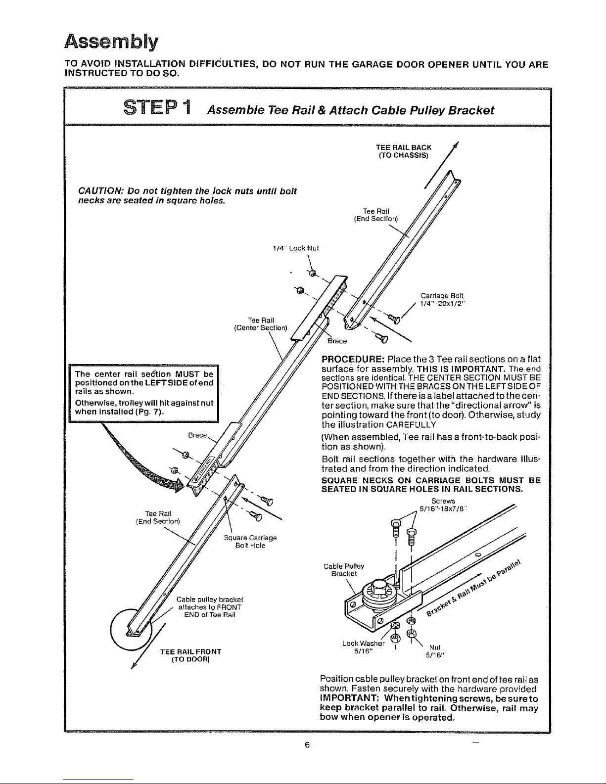
CAUTION: Do not tighten the lock nuts until bolt
necks are seated in square holes.
Tee Rail
(End Section)
t/4' Lock Nut
Tee Rail
The center rail section MUST be
positioned on the LEFTSIDE of end
rails as shown,
Otherwise, trolley will hit against nut
when installed (Pg. 7).
Brace
Tee Rail
(End Section)
Square Carriage
Bolt Hole
Cable pulley bracket
attaches to FRONT
END of Tee Rail
TEE RAIL FRONT
(TO DOOR)
Carriage Bolt
/2"
Brace _
PROCEDURE: Place the 3 Tee rail sections on a flat
surface for assembly. THIS IS IMPORTANT. The end
sections are identical. THE CENTER SECTION MUST BE
POSITIONED WITH THE BRACES ON THE LEFT SIDE OF
END SECTIONS. If there is a label attached to the cen-
ter section, make sure that the "directional arrow" is
pointing toward the front (to door) Otherwise, study
the illustration CAREFULLY
(When assembled, Tee rail has a front-to-back posi-
tion as shown).
Bolt rail sections together with the hardware illus-
trated and from the direction indicated
SQUARE NECKS ON CARRIAGE BOLTS MUST BE
SEATED IN SQUARE HOLES IN RAIL SECTIONS,
Screws
_ _5/16"_18x7/8""
Cable Pulley _ _,_';
k°ckW_s--_her_l _ Nut
5/16"
5/16"
Position cable pulley bracket on front end of tee rail as
shown. Fasten securely with the hardware provided
IMPORTANT: Whentighteningscrews, besureto
keep bracket parallel to rail, Otherwise, rail may
bow when opener is operated.
6
Assernbiy
STE P 2 Install Trolley & Attach Chain Retainer Bracket
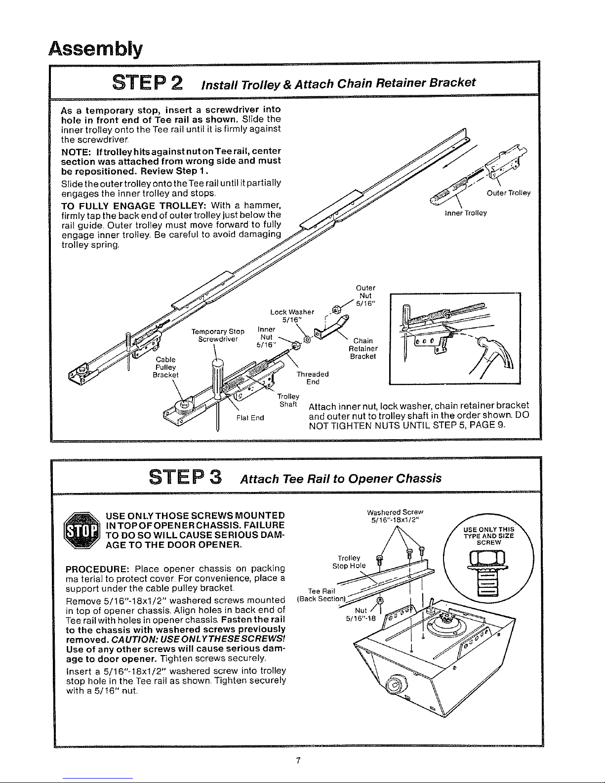
As a temporary stop, insert a screwdriver into
hole in front end of Tee rail as shown. Slide the
inner trolley onto the Tee rail until it is firmly against
the screwdriver
NOTE: If trolley hits against nut on Tee rail, center
section was attached from wrong side and must
be repositioned. Review Step 1.
Slide the outer trolley onto the Tee rail until it partially
engages the inner trolley and stops
TO FULLY ENGAGE TROLLEY: With a hammer,
firmly tap the back end of outer trolley just below the
rail guide Outer trolley must move forward to fully
engage inner trolley Be careful to avoid damaging
trolley spring,
Outer Trolley
Inner Trolley
Cable
Pulley
Bracket
\
Temporary Stop
Screwdriver
Flat End
Lock Washer
5/16"
Inner
Nut
Threaded
End
Outer
Nut
._5/16"
r
Chain
Retainer
Bracket
Trolley
Shaft
Attach inner nut, lock washer, chain retainer bracket
and outer nut to trolley shaft in the order shown_ DO
NOT TIGHTEN NUTS UNTIL STEP 5, PAGE 9,
STE P 3 Attach Tee Rail to Opener Chassis
USE ONLYTHOSE SCREWS MOUNTED
IN TOPOFOPEN ER CHASSIS. FAILURE
TO DO SO WILL CAUSE SERIOUS DAM-
AGE TO THE DOOR OPENER°
PROCEDURE: Place opener chassis on packing
ma terial to protect cover For convenience, place a
support under the cable pulley bracket
Re move 5/16"-18xl/2" washered screws mounted
in top of opener chassis Align holes in back end of
Tee ran with holes in opener chassis. Fasten the rail
to the chassis with washered screws previously
removed. CAUTION: USEONLYTHESESCREWS!
Use of any other screws will cause serious dam-
age to door opener. Tighten screws securely,
insert a 5/16"-18xl/2" washered screw into trolley
stop hole in the Tee rail as shown, Tighten securely
with a 5/16" nut
Washered Screw
5/16"-1Sxl/2"
Stop Hole
Tee Rall
(Back Sectior
5/16"-18
7
Assembly
STE P 4 I.stallChainandCable
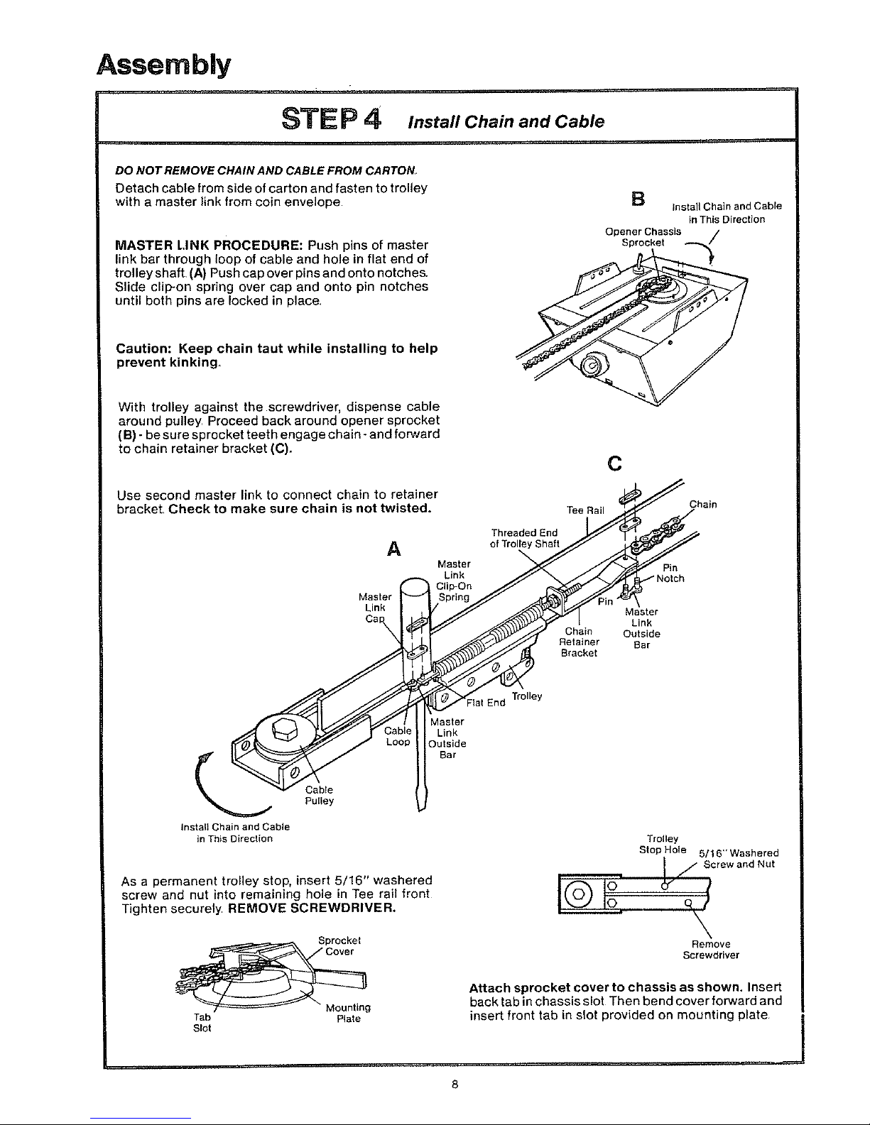
DO NOT REMOVE CHAIN AND CABLE FROM CARTON
Detach cable from side of carton and fasten to trolley
with a master link from coin envelope
MASTER LINK PROCEDURE: Push pins of master
link bar through loop of cable and hole in flat end of
trolley shaft (A) Push cap over pins and onto notches.
Slide clip-on spring over cap and onto pin notches
until both pins are locked in place,
I=!
installChainandCable
inThisDirection
Opener Chassis
Sprocket /
Caution: Keep chain taut while installing to help
prevent kinking,
With trolley against the screwdriver, dispense cable
around pulley Proceed back around opener sprocket
(B) - be sure sprocket teeth engage chain - and forward
to chain retainer bracket (C).
Use second master link to connect chain to retainer
bracket. Check to make sure chain is not twisted.
A
Pulley
Install Chain and Cable
in This D{recl[on
Master
Link
Clip-On
Spring
Master
Link
Outside
Bar
As a permanent trolley stop, insert 5/16" washered
screw and nut into remaining hole in Tee rail front
Tighten securely REMOVE SCREWDRIVER.
Tab Plate
Slot
C
Th_reo_rde_dsEhndTee Rail _ j Chain
Retaai_eetr ear
End Trolley
Trolley
St°P_H¢_ 5S/'Cr6ewWaan'h_ruetd
\
Remove
Screwdriver
Attach sprocket cover to chassis as shown, Insert
back tab in chassis slot Then bend cover forward and
insert front tab in slot provided on mounting plate
 Loading...