

Craftsman 139.53515SR User Manual
Sears Bestl/ZnnmMm
Owners Manual
Garage Door Opener
Model 139.53626SR - 1/2HP
Model 139.53515SR - 1/2HP
FASTEN THIS MANUAL NEAR THE GARAGE DOOR AFTER
INSTALLATION. PERIODIC CHECKS OF THE OPENER ARE
REQUIRED TO INSURE SATISFACTORY OPERATION.
FOR RESIDENTIAL USE ONLY.
CAUTION
PLEASE READ THIS
MANUAL CAREFULLY
CONTENTS
Safety Rules
Operation of Hbur Opener............... .. 3
Maintenance Schedule
Features of \bur Opener
Specifications................................... .. 4
Accessories......................................
Carton Check List
Y}u’ll Need Tools
Assembly
Installation Information
installation........................................
Force & Limit Adjustjnent
Safety Reverse Test......................... .. 18
Setting/Changing Code
Having a Problem 7
Repair Parts, Rail Assembly ...
Repair Parts, Installation
Repair Parts, Chassis Assembly
How To Order Repair Parts
Maintenance Agreements
Sears Warranty
.....................................
....................
..................
............................
.............................
.........................................
...................
...............
...................
.........................
................
______
...............
................................
PAGE
. 2
.. 3
. 4
. 4
.. 5
.. 6
. 9
.. 17
.. 19
.. 20
.. 22
.. 22
.. 23
.. 24
.. 24

start By Reading These Important Safety Rules
THIS SAFETY ALERT SYMBOL MEANS CAUTION — PERSONAL SAFETY OR PROPERTY
DAMAGE INSTRUCTION. READ THESE INSTRUCTIONS CAREFULLY.
THIS GARAGE DOOR OPENER IS DESIGNED AND TESTED TO OFFER REASONABLY
A
CAUTION: IF YOUR GARAGE HAS NO SERVICE ENTRANCE DOOR, INSTALL MODEL S3702 EMERGENCY RELEASE
KEYLOCK (PAGE 4). THIS ACCESSORY ALLOWS MANUAL OPERATION OF GARAGE DOOR FROM OUTSIDE IN CASE
OF POWER FAILURE,
SAFE SERVICE PROVIDED IT IS INSTALLED AND OPERATED IN STRICT ACCORDANCE
WITH THE FOLLOWING SAFETY INSTRUCTIONS.
FAILURE TO COMPLY WITH THE FOLLOWING INSTRUCTIONS MAY RESULT IN SERIOUS
PERSONAL INJURY OR PROPERTY DAMAGE.
A
A
A
A
KEEP GARAGE DOOR BALANCED. Sticking or
binding doors must be repaired. Garage doors,
door springs, cables, pulleys, brackets and their
hardware are under extreme tension and can
cause serious personal injury. DO NOT
ATTEMPT TO LOOSEN, MOVE OR ADJUST
THEM. Call a garage door serviceman.
DO NOT WEAR RINGS, WATCHES OR LOOSE
CLOTHING while installing or servicing a garage
door opener.
To avoid serious personal injury from entangle-
menL REMOVE ALL ROPES CONNECTED TO
THE GARAGE DOOR before installing the
garage door opener.
DISENGAGE ALL EXISTING GARAGE DOOR
LOCKS to avoid damage to garage door.
Installation and wiring must be in compliance
with your local building and electrical codes.
CONNECT THE POWER CORD ONLY TO A
PROPERLY GROUNDED OUTLET.
A
A
A
A
THE SAFETY REVERSE SYSTEM TEST IS VERY
IMPORTANT (page 18). Ysur garage door MUST
reverse on contact with a 1' obstacle placed on
the floor. Failure to properly adjust the opener
may result in serious personal injury from a
closing garage door. REPEAT THE TEST AT
LEAST ONCE EVERY THREE MONTHS AND
MAKE NEEDED ADJUSTMENTS.
Fasten the CAUTION LABEL alongside the Wall
Control as a reminder of safe operating
procedures.
Install the Wall Control (or any additional push
buttons) IN A LOCATION WHERE THE GARAGE
DOOR IS VISIBLE, BUT OUT OF THE REACH OF
CHILDREN. DO NOT ALLOW CHILDREN TO
OPERATE THE WALL PUSH BUTTON(S) OR
TRANSMITTER. Serious personal injury from a
closing garage door may result from misuse of
the opener.
CAUTION: Activate opener only when the door
is in tuli view, free of obstructions and opener
is properly adjusted. NO ONE SHOULD ENTER
OR LEAVE THE GARAGE WHILE DOOR IS IN
MOTION. DO NOT ALLOW CHILDREN TO PLAY
NEAR THE DOOR.
A
A
LIGHTWEIGHT FIBERGLASS, ALUMINUM AND
STEEL DOORS MUST BE SUBSTANTIALLY
REINFORCED TO AVOID DOOR DAMAGE. (See
page 15.) The best solution is to check with your
garage door manufacturer for an opener
installation reinforcement kit.
DO NOT USE THE FORCE ADJUSTMENTS TO
COMPENSATE FOR A BINDING OR STICKING
GARAGE DOOR. Excessive force will interfere
with the proper operation of the safety reverse
system or damage the garage door (page 17).
A
A
Use the emergency release ONLY to disengage
the trolley and, if possible, ONLY when the door
is closed. DO NOT USE EMERGENCY HANDLE
TO PULL DOOR OPEN OR CLOSED.
DISCONNECT ELECTRIC POWER TO GARAGE
DOOR OPENER BEFORE MAKING REPAIRS OR
REMOVING COVERS.

Operation of Your Opener
CAUTION
BEFORE YOU PROCEED, PLEASE READ THE
SAFETY RULES ON PAGE 2 AND OPERATING
INSTRUCTIONS ON THIS PAGE CAREFULLY.
TO AVOID DIFFICULTY DURING INSTALLATION, DO
NOT RUN OPENER UNTIL INSTRUCTED TO DO SO.
USING THE OPENER
Your opener can be activated by any of the following devices:
1. The 3-Function Transmitter. Hold LARGE push button
down until the door starts to move.
2. The Wall Control. Hold push bar down until the door starts
to move.
3. The Key Switch or Touch Code Transmitter accessories.
Descried on page 4.
OPENING THE DOOR MANUALLY
THE DOOR SHOULD BE FULLY CLOSED IF POSSIBLE. WEAK OR
BROKEN SPRINGS COULD ALLOW AN OPEN DOOR TO FALL
RAPIDLY. PROPERTY DAMAGE OR SERIOUS PERSONAL INJURY
COULD RESULT. DO NOT USE EMERGENCY HANDLE TO PULL
DOOR OPEN OR CLOSED.
The door can be operated manually by disconnecting it from
the opener. Pull down sharply on the red emergency release
handle and lift the door manually. To automatically reconnect
the door to the opener, press the Wall Control push bar.
LOCKOUT FEATURE: prevents trolley from reconnecting
automatically. If you need to use this feature, pull emergen^
handle down and back (toward the opener). Trolley will remain
"Locked-Out" and door can be raised and lowered manually.
To reconnect trolley, pull emergency handle straight down.
• DO NOT PERMIT CHILDREN TO PLAY IN DOOR
AREA.
• OPERATE ONLY WHEN OPENER IS PROPERLY
ADJUSTED AND THE DOOR IS VISIBLE AND
UNOBSTRUCTED.
WHEN OPENER IS ACTIVATED:
1. If open, the door will close. If closed, the door will open.
2. If closing, the door will reverse.
3. If opening, the door will stop (allowing space for entry and
exit of pets and for fresh air),
4. If the door has been stopped in a partially open position,
it will close.
5. If an obstruction is encountered while closing, the door will
reverse.
6. if an obstruction is encountered while opening, the door
will stop.
7. If the optional ‘Infrared Sensor’ is installed, the garage door
will reverse in the closing cycle when the invisible beam
is broken. An open door will not close when beam is broken.
The sensor has no effect in the opening cycle.
OPENER LIGHTS will turn on under the following conditions:
when the opener is initially plugged in; when the power is
interrupted; when the opener is activated. They will turn off
automatically after 4’/i minutes or provide constant light when
Light Feature is activated. Bulb size 75 watts maximum.
CARE OF THE OPENER
When properly instiled, opener will provide high performance
with a minimum of maintenance. The opener does not require
additional lubrication.
Most complaints of unsatisfactory opener operation can be
traced to problems with the door itself. When operated
manually, a properly balanced door will stay in any point of
travel while being supported entirely by its springs.
THE OPENER IS NOT INTENDED TO CORRECT ANY
PROBLEMS THAT ARE CAUSED BY AN UNBALANCED OR
BINDING DOOR, BROKEN DOOR SPRINGS OR BY FAULTY
DOOR HARDWARE.
LIMIT AND FORCE ADJUSTMENTS: These a(fjustments
must be checked and properly set when opener is installed.
Only a screwdriver is required. Page 17 refers to the limit and
force adjustments. Follow instructions carefully.
REPEAT SAFETY REVERSE TEST AFTER ANY ADJUST
MENT OF FORCE AND/OR LIMITS. Weather conditions
may cause some minor changes in door operation requir
ing some readjustments, particularly during the first year
of operation.
THE SAFETY REVERSE SYSTEM IS IMPORTANT (See
pg. 18). GARAGE DOOR MUST REVERSE ON CONTACT
WITH A ONE-INCH OBSTACLE PLACED ON THE FLOOR.
FAILURE TO PROPERLY ADJUST OPENER MAY RESULT
IN SERIOUS PERSONAL INJURY FROM A CLOSING
GAR.<\GE DOOR.
CHAIN TENSION ADJUSTMENT; After installation of the
opener and adjustment of forces and limits, the chain may
appear loose. This is normal. To check the chain tension:
disconnect the trolley by pulling the red emergency handle.
If the chain returns to the position described and illustrated
in Step 5 page 9, DO NCT make ANY further adjustments.
TRANSMITTER; The 3-function transmitter will operate more
than one garage door opener, if desired. The other push but
tons may also be used to operate 53000 and 53000SR Series
light controls. Transmitter may be secured to car sun visor
with clip provided. Additional transmitters can be purchased
at any time. Refer to Accessories on page 4.
Any new transmitters must be set to the same code as the
original transmitter. Page 19 explains how to change your
existing code and use the transmitter(s) with other 53000 and
53000 SR receivers. Self service of your radio controls is rwt
recommended. If service is needed, contact your nearest
Sears Service Center.
TRANSMITTER BATTERY: The 12 Vblt battery should
produce power for at least one year. As long as the battery
power is adequate, the transmitter test light will glow when
the push button is pressed (and the opener will operate).
When the light does not come on, replace the battery. If trartsmission range lessens, check battery test light.
TO CHANGE BATTERY Slide №e battery compartment cover
down. Position new 12 Volt battery as directed.
MAINTENANCE OF YOUR OPENER
AT LEAST 4 TIMES A YEAR
MANUALLY OPERATE DOOR. If it is unbalanced or birfoing,
call for professional garage door service.
CHECK TO BE SURE DOOR OPENS & CLOSES FULLY.
Adjust Limits and/or Force if necessary.
REPEAT SAFETY REVERSE TEST. Make any necessary
adjustments (see page 18).
TWICE A YEAR
CHECK CHAIN TENSION. Adjust if necessary.
ONCE A YEAR
OIL DOOR ROLLERS, BEARINGS AND HINGES.
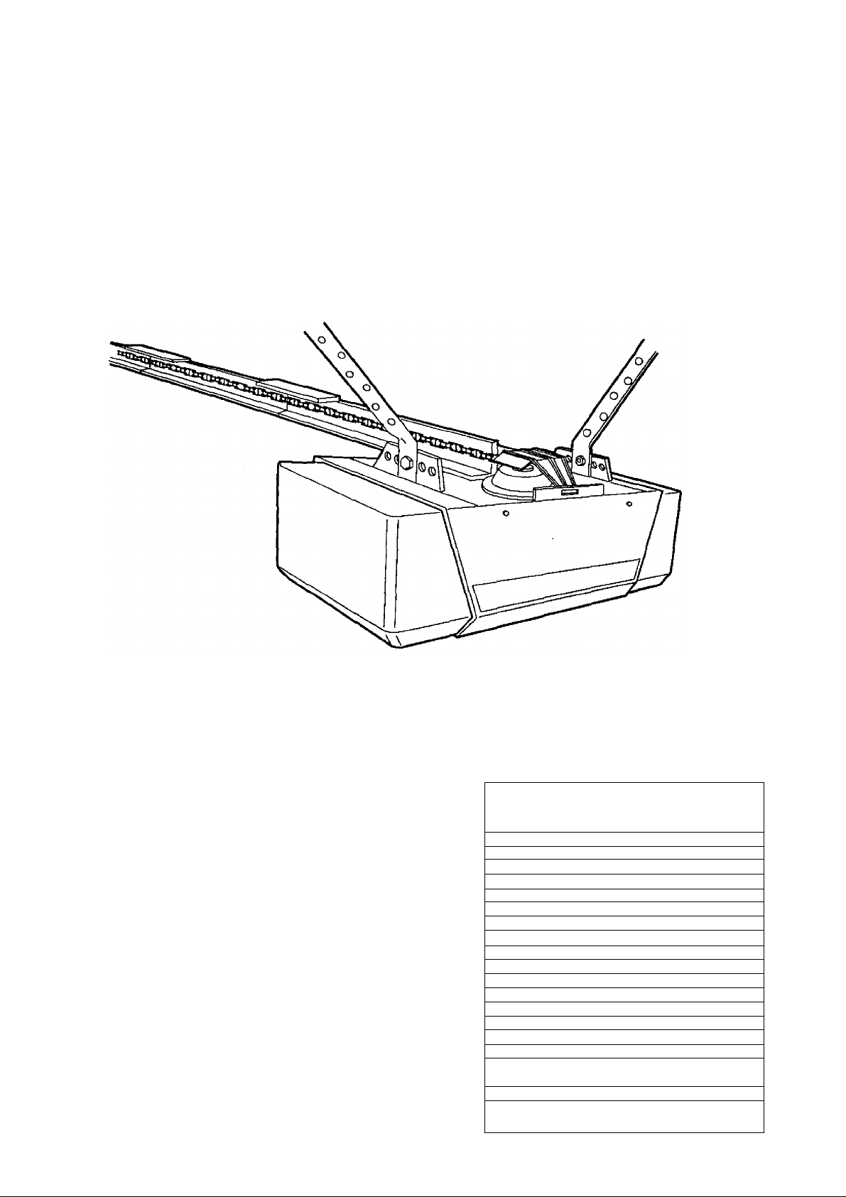
FEATURES OF YOUR OPENER
1. Motor: Permanently lubricated with automatic reset.
2. Opener Lights: Turn on and off automatically with ЛУг
minute illumination for your safety and convenience.
Provide constant fight when Light Feature is activated.
3. Safety System: Independent up and down force
adjustment. The door reverses automatically when
obstructed in DOVVN direction. The door STOPS when
obstructed in UP position
4. Easy Limit Adjustment: Limits of door opening and
closing adjust^ by turning screws without removing
chassis cover.
5. Digital Radio Controls: The code can be easily
changed by the owner,
6. Emergency Disconnect: Pull cord disconnect permits
manual door operation.
7. 3-Function Transmitter: Has three push buttons. Each
button can activate one or more remote control devices.
Opener is factory preset to activate when LARGE push
button on transmitter is pressed.
8. Automatic Reconnect: The trolley halves reconnect
for automatic operation when the opener is energized
after emergency disconnect.
9. Lock Push Button: When Lock Feature is activated,
opener will not operate from portable transmitters. Door
will OPEN from Wall Control push bar, Key Switch and
Touch Code Transmitter accessories, described below.
Door will CLOSE if Wall Control push bar is pressed
and held through a complete down cycle. If push bar
is released before travel Is completed, door will reverse.
SPECIFICATIONS
MOTOR
Type
................................
Speed............................. 1500 rpm
\folts
...............................
Current
..........................
Gears
..............................
Drive
..............................
Length of travel
Travel rate
Lamps
Door linkage..................Adjustable door arm. Pull cord trolley
......................
............................
Permanent split capacitor
120 Volts AC - 60 Hz. Only
45 amperes
DRIVE MECHANISM
16:1 worm gear reduction
Chain & cable with two-piece trolley on
steel Tee-rail
............
Adjustable to Th leet
6 to 8 inches per second
On when door starts in travel, off 4’A
minutes after stop. Constant light when
Light Control is ON.
release.
Personal........................Push button and automatic reversal in
Electronic......................Independent UP and DOWN force
Electrical
Limit device
Limit adjustment
Start circuit
Length (overall)
Headroom required .. 2 inches
Hanging weight
.......................
.................
...................
SAFETY
down direction. Push button and
Automatic stop in UP direction
adjustment screws
Motor overload protector & low voltage
push button wiring
Circuit actuated by limit nut
..........
Screwdriver adjustment on side panel
Low voltage push button or radio
control
DIMENSIONS
............
124 inches
............
32 pounds
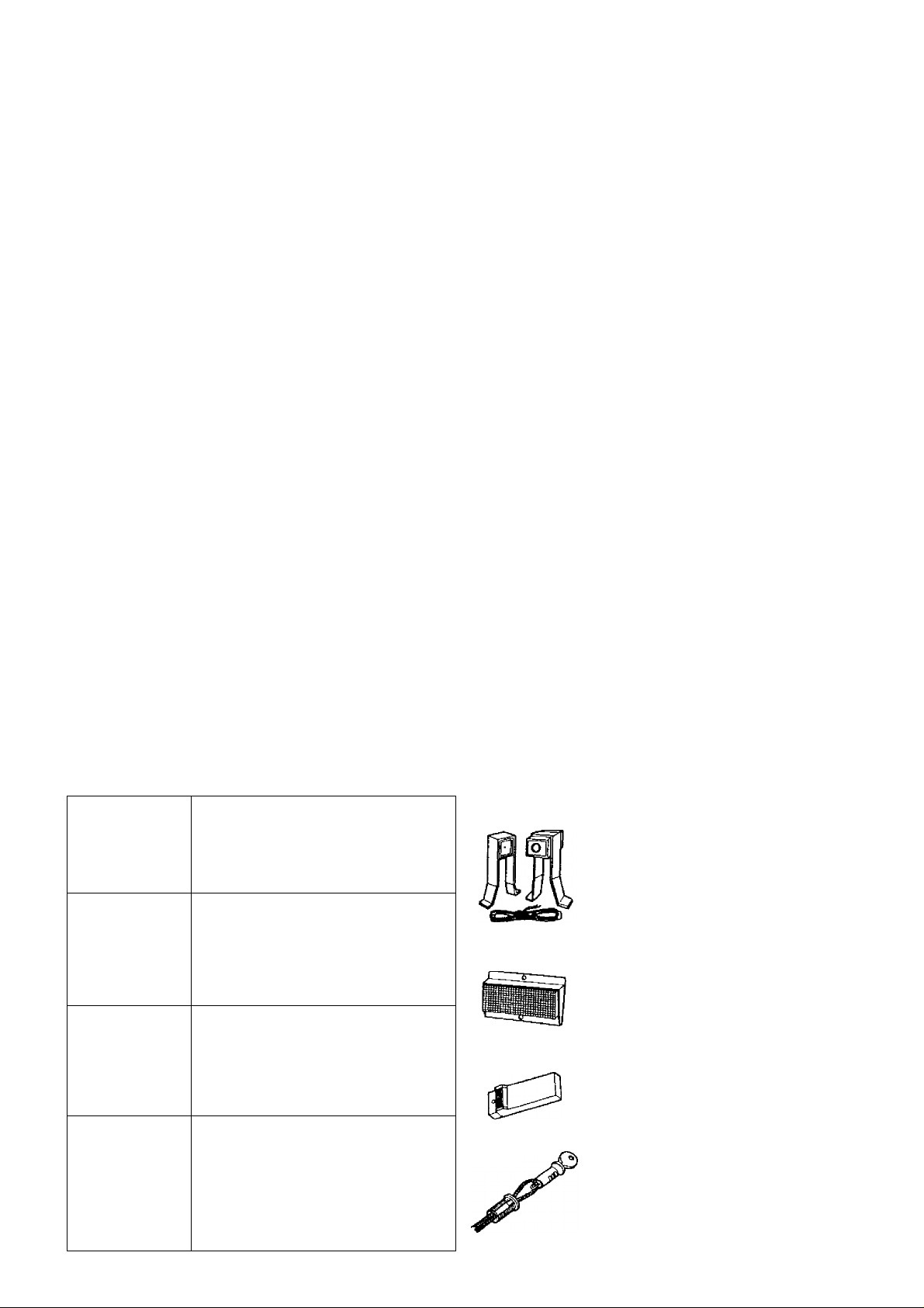
ACCESSORIES
Sears offers many useful accessories for your garage door opener. They are illustrated below with sears stock
numbers and descriptions.
53778 _^^
53758
EXTRA TRANSMITTER:
Standard size. Includes visor clip.
EXTRA TRANSMITTER:
Mini.
53710
53717
INFRARED REVERSING SENSOR:
An optional system which provides
auxiliary support to the safety features
built into your opener. If the sensor's
invisible beam is broken, a closing
door will reverse and an open door will
not close.
OPEN DOOR INDICATOR:
Provides an illuminated signal when
your garage door is open.
53703
53709
OUTDOOR KEY SWITCH:
Opens the garage door automatically
from outside when transmitter is not
handy.
DOOR CLEARANCE BRACKETS:
(For Sectional Doors Only)
Replace top brackets and rollers on
door to reduce height of door travel.
For use when installing opener in
garage with low headroom clearance.
53776
53702
TOUCH CODE TRANSMITTER:
Enables homeowner to operate garage
door opener from outside by entering
code on specially designed keyboard.
EMERGENCY RELEASE KEYLOCK
REQUIRED for a garage with NO
service door.
Allows manual operation of garage
door from outside in case of power
failure.
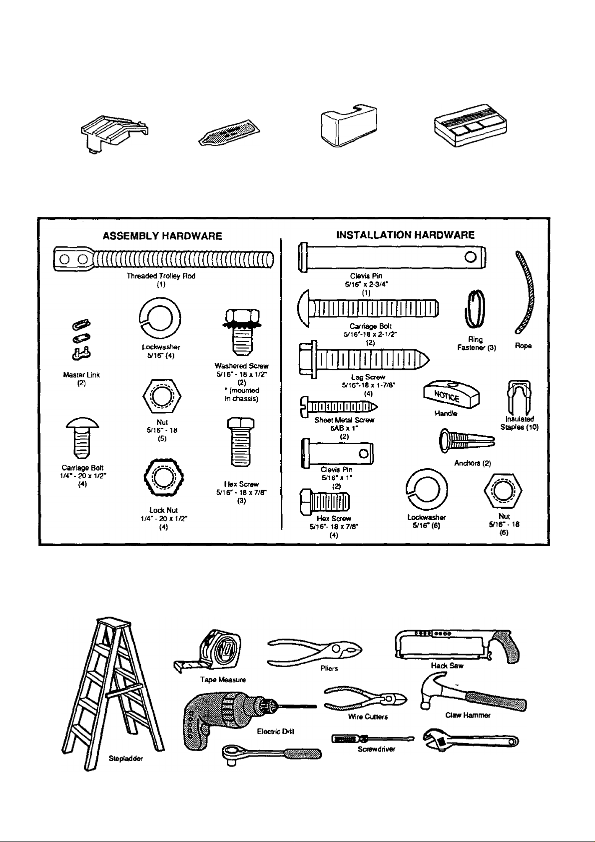
CARTON CHECK LIST
SEARS has packaged your GARAGE DOOR OPENER in two cartons which contain all the parts and hardware
Illustrated below and on Page 22.
Sprockel
Cower
Rail
Grease
Light
Lees (2)
3 Function Tiaosmitter
Model 139.53626 (1)
Model 139.53515 (2)
SEPARATE ALL HARDWARE FOR ASSEMBLY AND INSTALLATION PROCEDURES AS SHOWN BELOW.
YOU'LL NEED TOOLS
During assembly and installation of your opener, the Instructions will call for the use of various hand tools. Have a
stepladder handy, and those tools Illustrated below; hammer, electric drill (& 3/l6"and S/I6"drlll bits), screwdriver,
adjustable end wrench or socket wrench kit, wire cutters, tape measure, pliers and hack saw.
Socket Wrench
At^etable End Wrench
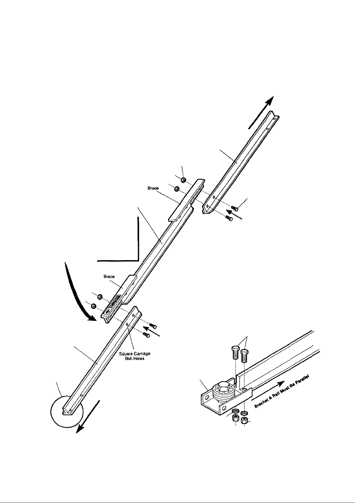
Assembly
TO AVOID INSTALLATION DIFFICULTIES, DO NOT RUN THE GARAGE DOOR OPENER UNTIL INSTRUCTED TO DO SO.
STEP 1 Assemble Tee Rail & Attach Cable Pulley Bracket
TEE RAIL BACK
(TO CHASSIS)
Tee Rail
CAUTION: Do not tighten the lock nuts until bolt necks
sre seated in square holes.
Tee Rail
(Center Section)
1/4“ Lock Nut
(End Section)
Carriage Bolt
1/4--20X1/2*
The end sections of the rsil MUST be
connected to the center section from
the direction shown in the illustration.
Otherwise, the trolley will hit against
the nut when installed (Pg. 7).
Tee Ral
(End Section)
Cable pulley bracket
attaches to FRONT
END of tee rail
PROCEDURE: Place the 3 Tee rail sections on a flat
surface for assembly. THIS IS IMPORTANT. The end
sections are identical. THE CENTER SECTION BRACES
MUST BE POSITIONED AGAINST THE END SECTIONS
AS SHOWN. Make sure that the “directional arrow’’is
pointing toward the front (to door). Study the illustration
CAREFULLY.
(When assembled. Tee rail has a front-to-back position as
shown.)
Bolt rail sections together with the hardware illustrated arxl
from the direction indicated.
SQUARE NECKS ON THE CARRIAGE BOLTS MUST BE
SEATED IN THE SQUARE HOLES IN RAIL SECTIONS.
Screws
8x7/8"
Cable Pulley
Bracket
TEE RAIL FRONT
(TOEXXJR)
Lock Washer
5/16"
Nut
-5/16"
Position the cable pulley bracket on front end of tee rail
as shown. Fasten securely with the hardware provided.
IMPORTANT: When tightening screws, be sure to keep
bracket parallel to rail. Otherwise, rail may bow when
opener is operated.
Assembly
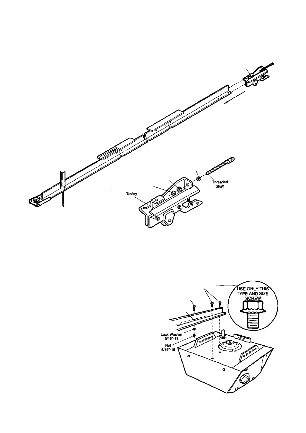
STEP 2 Install Trolley
AS A TEMPORARY STOP, INSERT A SCREWDRIVER
INTO HOLE IN FRONT END OF TEE RAIL AS SHOWN.
1. Attach threaded shaft to trolley with lockwasher and n uts
as shown.
2. Slide trolley assembly along rail to screwdriver stop.
NOTE: If trolley hits against the nut on Tee rail, center
section was attached from wrong side and must be
repositioned. Review Step 1.
Temporary Stop
Screwdriver
Inner Nut
5/16*
Trolley
Outer Nut
5/16'
Lock Waalner
5/16*
STEP 3 Attach Tee Rail To Opener Chassis
USE ONLY THOSE SCREWS MOUNTED IN
TOP OF OPENER CHASSIS. FAILURE TO DO
A
PROCEDURE: Place the opener chassis on packing
material to protect the cover. For convenience, place a
support under the cable pulley bracket.
Remove 5/16'-18 x 1/2' washered screws mounted in top
of opener chassis. Align hoies in back end of Tee rail with
holes in opener chassis. Fasten the raii to the chassis
with washered screws previously removed. CAUTION:
USE ONLY THESE SCREWS! Use of any other screws
will cause serious damage to door opener. Tighten
screws secureiy.
insert a 5/16'-16 X 7/8' hex screw into trolley stop hole in
the Tee rail as shown. Tighten securely with a 5/16* lockwasher and nut.
SO WILL CAUSE SERIOUS DAMAGE TO THE
OPENER.
Hex Screw
5/16*-18x7/8'
Trolley
Stop Hole
Tee Rail
(Back Section)
Washered Screw
5/16"-18x1/2*
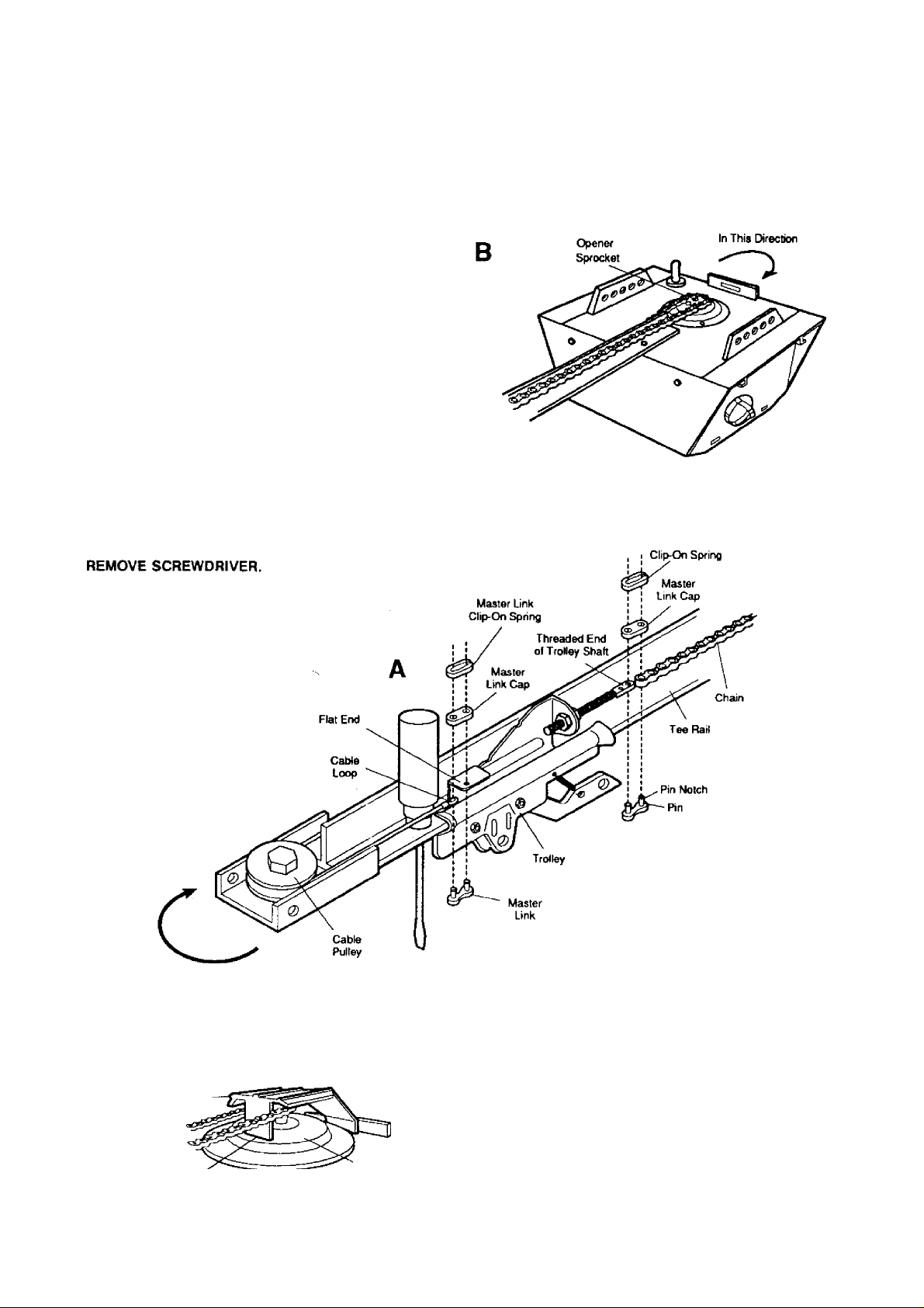
Assembly
STEP 4 Install Chain and Cable
DO NOT REMOVE CHAIN AND CABLE FROM CARTON.
Detach cable from side of carton. Remove master links
from coin envelope. .
MASTER LINK PROCEDURE: Insert pins of master link
bar through cable loop and hole in front end of trolley (A)
as shown. Push cap over pins and onto notches. Slide clipon spring over cap and onto pin notches until pins are
locked in place.
Caution: Keep the chain taut while installing to help
prevent kinking.
With trolley against the screwdriver, dispense cable around
pulley. Proceed back around opener sprocket (B)- be sure
sprocket teeth engage chain- and forward to the threaded
trolley shaft (C).
Use second master link to connect the chain to the flat
end of shaft as shown. Check to make sure chain is not
twisted.
Install Chain
Master Link
instaJI Chain and Cable
In This Direction
Sprocket
Cover
Tab Slot
Mounting
Plate
ATTACH SPROCKET COVER TO CHASSIS:
insert back tab in chassis slot. Then bend cover forward
and insert front tab in slot provided on mounting plate.
 Loading...