

Page 1
,';o’"" - rTT) ‘ -/T^,,1
- —- - -'-
Owners Manual
Garage Door Opener
Model 139.535006
CAUTION: READ INSTRUCTIONS AND RULES
FOR SAFE OPERATION CAREFULLY.
FASTEN THIS MANUAL NEAR THE GARAGE
DOOR AFTER INSTALLATION. PERIODIC
CHECKS OF OPENER ARE REQUIRED
TO INSURE SATISFACTORY OPERATION.
IWDEX
Features of Your Opener
Specifications
You’ll Need Tools
Safety Rules —...........
Carton Check List
Accessories
Identify Your Door Type
Assembly
Installation
Adjustment................................
Operation of Your Opener
Radio Controls
Having a Problem?......
Transmitter Schematic
Wiring Diagram
Receiver Schematic
Repair Parts, Rail Assembly ....
Repair Parts, installation
Repair Parts, Chassis Assembly
How to Order Repair Parts......
Maintenance Agreements
Sears Warranty
.................
.....................................
....................................
.................
..............
................................
_________
_____
......................
.
..................
_____
_
________
.......................
..........
.....................
_________
..............
.............
..................28
____
_______
....
.
.......
___
........
.......
„
_
.
Page
....
2
... 2
... 2
....
3
.
...
4
... 5
... 5
.,. 6
....
10
... 18
... 21
... 22
...24
...24
...25
....
25
....
26
...26
....
27
... 28
... 28
Page 2
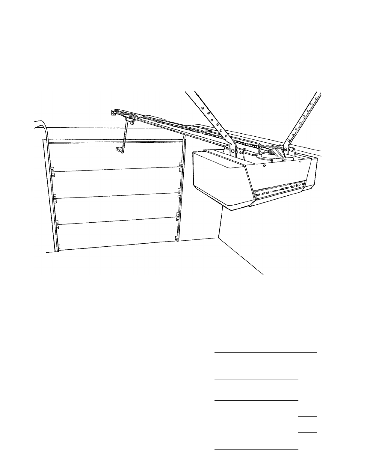
FEATURES OF YOUR OPENER
, Opener Lights: Turn on and off automatically,
with 4-1/2 minute illumination for your safety and
convenience. Provide constant light when Work
Light control button is pressed,,
, Safety System: Independent up and down force
adjustment Door reversesautomatically when ob
structed in DOWN direction Door STOPS when
obstructed in UP direction.
Emergency Disconnect: Pull cord disconnect
permits rnanuai door operation.
Automatic Reconnect: Trolley halves reconnect
for automatic operation when opener is energized
after emergency disconnect
SPECIFICATIONS
MOTOR
Type .
Speed
Volts .,
Current
Gear reduction
Drive
Lubrication
Length of Travel
Travel rate
Lamp
Door linkage
1/2 horsepower permanent split capacitor
, 1500 rpm
120 Volts AC - 60 Hz Only
4,5 amperes
DRIVE MECHANISM
16:1
Chain & cable with two-piece trolley on
steel Tee rail
Motor is seif-lubricated. Drive shaft bronze
oil-life bearings
Adjustable to 7-1/2 feet
6 to 8 inches per second
On when door starts in travel, off 4-1/2
minutes after stop. Also separate Work
Light push button
Adjustabie door arm Pull cord trolley
release
5. Motor Power: 1/2 horsepower permanently lubri
cated motor with automatic reset
6. Digital Radio Controls: 19,683 codes from which
to choose Can be changed easily by the owner.
7. Easy Limit Adjustment: Limits of door opening
and closing adjusted by turning screws without r e
moving chassis cover,
8. Vacation Push Button: When the Vacation Push
Button is ON, the opener wil! not operate from the
transmitter. The door will operate in the UP direc
tion ONLY from the Wali Control (or optional Key
Switch accessory, Page 5)
SAFETY
Personaf
Electronic
Electrical
Limit device. ...
Limit adjustment
Start circuit
Length (overall) . .
Headroom required
Shipping Weight
Push button S automatic reversal in down
rlirection. Push button S automatic stop
in up direction
Independent up a down force adjustment
screws
Motor overload protector and tow voltage
push button wiring
Circuit actuated by limit nut
Screwdriver adjustment on side panel
Low voltage push button or radio control
DIMENSIONS
122-1/2 inches
2 inches
43 pounds
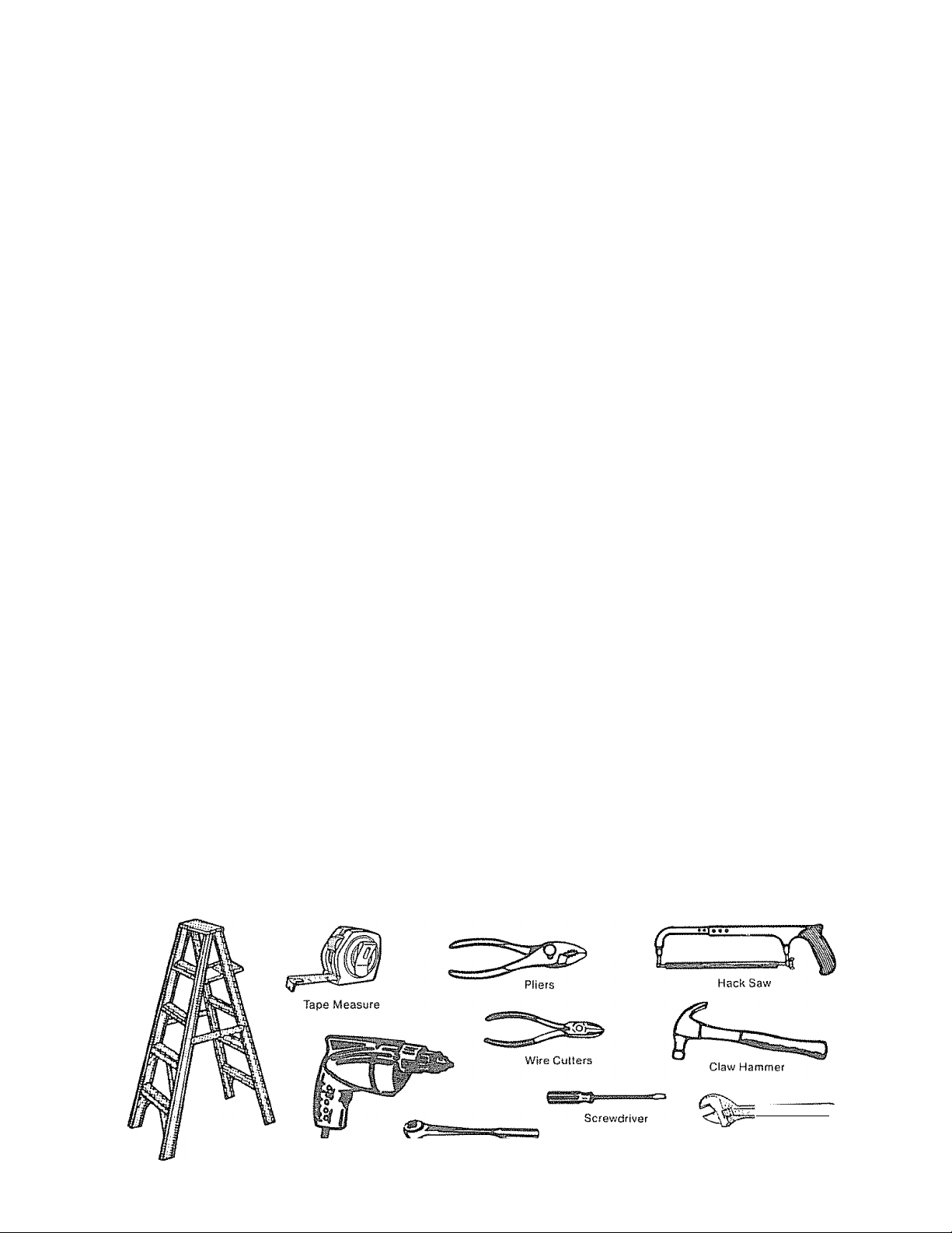
YOU’LL NEED TOOLS
During assembly and instaliaflon of your opener, the instruction will call for use of various hand tools. Have a
stepladder handy, and those tools illustraled below: Hammer, electric drill (also 3/16" and 5/16" drill bits), screw
driver, adjustable end wrench or socket wrench kit, wire cutters, tape measure, pliers and hack saw.
. SOI
stepladder
Electric Drill
Socket Wrench
Adjustable End Wrench
Page 3
Start By
Reading
THIS SAFETY ALERT SYMBOL MEANS CAUTION - PERSONAL SAFETY OR PROPERTY DAMAGE IN
STRUCTION, READ THESE INSTRUCTIONS CAREFULLY.
THIS GARAGE DOOR OPENER IS DESIGNED AND TESTED TO OFFER REASONABLY SAFE SERVICE
PROVIDED IT IS INSTALLED AND OPERATED IN STRICT ACCORDANCE WITH THE FOLLOWING
SAFETY INSTRUCTIONS,
FAILURE TO COMPLY WITH THE FOLLOWING INSTRUCTIONS MAY RESULT IN SERIOUS PERSONAL
INJURY OR PROPERTY DAMAGE,
These Important Safety Rules
KEEP GARAGE DOOR BALANCED, STICKING
OR BINDING DOORS MUST BE REPAIRED
GARAGE DOORS, DOOR SPRINGS, CABLES,
PULLEYS, BRACKETS ANDTHEIR HARDWARE
MAY BE UNDER EXTREME TENSION ANDCAN
CAUSE SERIOUS PERSONAL INJURY. DO NOT
ATTEMPT ADJUSTMENTS. CALL A GARAGE
DOOR SERVICEMAN TO MOVE, LOOSEN OR
ADJUST DOOR SPRINGS OR HARDWARE.
DO NOT WEAR RINGS, WATCHES OR LOOSE
CLOTHING WHILE INSTALLING OR SERVICING
A GARAGE DOOR OPENER,
TO AVOID SERIOUS PERSONAL INJURY FROM
ENTANGLEMENT, REMOVE ALL ROPES CON
NECTED TO THE GARAGE DOOR BEFORE IN
STALLING THE GARAGE DOOR OPENER
DISENGAGE ALL EXISTING GARAGE DOOR
LOCKS TO AVOID DAMAGE TO GARAGE DOOR-
DO NOT USE FORCE ADJUSTMENTSTOCOMPENSATE FOR A BINDING OR STICKING
GARAGE DOOR. EXCESSIVE FORCE WILL IN
TERFERE WITH THE PROPER OPERATION OF
THE SAFETY REVERSE SYSTEM OR DAMAGE
THE GARAGE DOOR (SEE PAGE 19).
FASTEN THE CAUTION LABEL ON THE WALL
NEAR THE WALL CONTROL AS A REMINDER
OF SAFE OPERATING PROCEDURES.
INSTALL THE WALLCONTROLjOR ADDITION
AL PUSH BUTTONS) OUT OF THE REACH OF
CHILDREN, DO NOT ALLOW CHILDREN TO
OPERATE WALL CONTROL OR TRANSMITTER.
SERIOUS PERSONAL INJURY FROM A CLOS
ING GARAGE DOOR MAY RESULT FROM ANY
MISUSE OF THE OPENER.
INSTALLATION AND WIRING MUST BE IN COM
PLIANCE WITH LOCAL BUILDING AND ELEC
TRICAL CODES
LIGHTWEIGHT DOORS REQUIRE SUBSTAN
TIAL REINFORCEMENT TO AVOID DOOR
DAMAGE. (SEE PAGE 10).
THE SAFETY REVERSE SYSTEM TEST IS IM
PORTANT (SEE PAGE 20), THE GARAGE DOOR
MUST REVERSE ON CONTACT WITH A ONE-
INCH OBSTACLE PLACED ON THE FLOOR
FAILURE TO PROPERLY ADJUST THE OPENER
MAY RESULT IN SERIOUS PERSONAL INJURY
FROM A CLOSING GARAGE DOOR. REPEAT
THE TEST AT LEAST ONCE A YEAR AND MAKE
ANY NEEDED ADJUSTMENTS,
CAUTION; ACTIVATE OPENER ONLY WHEN
THE DOOR IS IN FULL VIEW, FREE OF OB
STRUCTION AND OPENER IS PROPERLY AD
JUSTED. NO ONE SHOULD ENTER OR LEAVE
THE GARAGE WHILE DOOR IS IN MOTION,
DO NOT ALLOW CHILDREN TO PLAY NEAR
DOOR.
USE EMERGENCY RELEASE ONLY TO DIS
ENGAGE TROLLEY.. DO NOT USE RED EMER
GENCY RELEASE ROPE AND HANDLE TO PULL
DOOR OPEN OR CLOSED.
DISCONNECT ELECTRIC POWER TO GARAGE
DOOR OPENER BEFORE MAKING REPAIRS
OR REMOVING COVERS.
Page 4
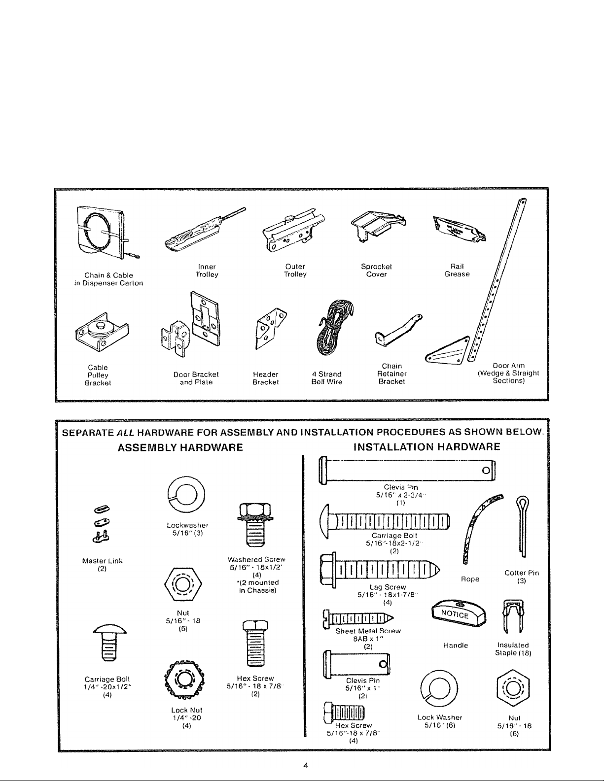
CARTON CHECK LIST
SEARS has packaged your Garage Door Opener in two cartons THE RAIL ASSEMBLY CARTON CONTAINS; a
three-piece rail, two hanging straps, straight door arm section* and rail assembly hardware.
THE OPENER CARTON CONTAINS:
Opener Chassis Wall Control Header Bracket*
Plastic Light Lenses (2) Sprocket Cover* 4-Strand Bell Wire*
Transmitter and Clip (1) Cable Pully Bracket* Owners Manual
Chain & Cable (in dispenser carton)* Door Bracket & Plate* Hardware Bag
2-Piece Trolley* Wedge Door Arm Section* (includes Caution Label)
‘ILLUSTRATED BELOW
Page 5
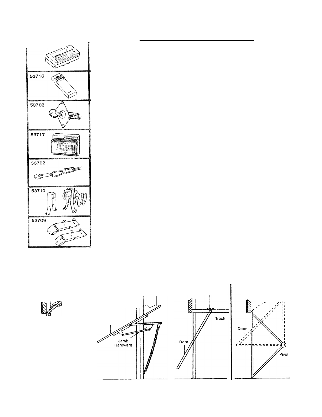
Accessories
Sears offers many useful accessories foryour garage door opener. They are illustrated below with Sears stock num
bers and descriptions.
" EXTRA TRANSMITTER: Includes visor clip.
.............................
TOUCH CODE LOCK: Enables homeowner to open the garage door opener from the
...............................................................................
....................
outside by entering code on specially designed keypad
OUTDOOR KEY SWITCH: Opens the garage door automatically from outside when
transmitter is not handy
OPEN DOOR INDICATOR: Provides an illuminated signal when your garage door
Is open
QUICK RELEASE KEY LOCK: Allows manual operation of yourgaragedoorfrom the
outside in case of power failure or where there is no service entrance For wood or
metal doors only
SECTIONAL DOOR
CURVED TRACK
Highest Point of Travel
---
1—
Track
INFRARED REVERSING SENSOR: An optional system which provides auxiliary
support to the safety features built into your opener. Sensors detect any obstruction
to your door while in the down cycle and transmit a signal to the opener. The opener
will cause a closing door to reverse and prevent an open door from closing.
FOR SECTIONAL DOORS ONLY
QUICK TURN BRACKETS: Replace top brackets and rollers on door to reduce
height of door travel For use when installing opener in garage with low head
room clearance
IDENTIFY YOUR DOOR TYPE FROM THESE ILLUSTRATIONS
ONE PIECE DOOR
NO TRACK
JAMB HARDWARE
Highest PoinI of Travel
^ -
Door
ONE PIECE DOOR
HORIZONTAL TRACK
JAMB HARDWARE
Highest Point ot Travel
ONE PIECE DOOR
NO TRACK
PIVOT HARDWARE
Highest Point of Travel
)
---------
Door
CERTAIN INSTALLATION PROCEDURES VARY ACCORDING TO GARAGE DOOR TYPES. WHERE DIFFERENCES
OCCUR. BE SURE TO FOLLOW ONLY THOSE INSTRUCTIONS WHICH APPLY TO YOUR DOOR
CONSTRUCTION
Page 6
Assembly
TO AVOID INSTALLATION DIFFICULTIES, DO NOT RUN THE GARAGE DOOR OPENER UNTIL YOU HAVE
COMPLETED STEPS, PAGE 15.
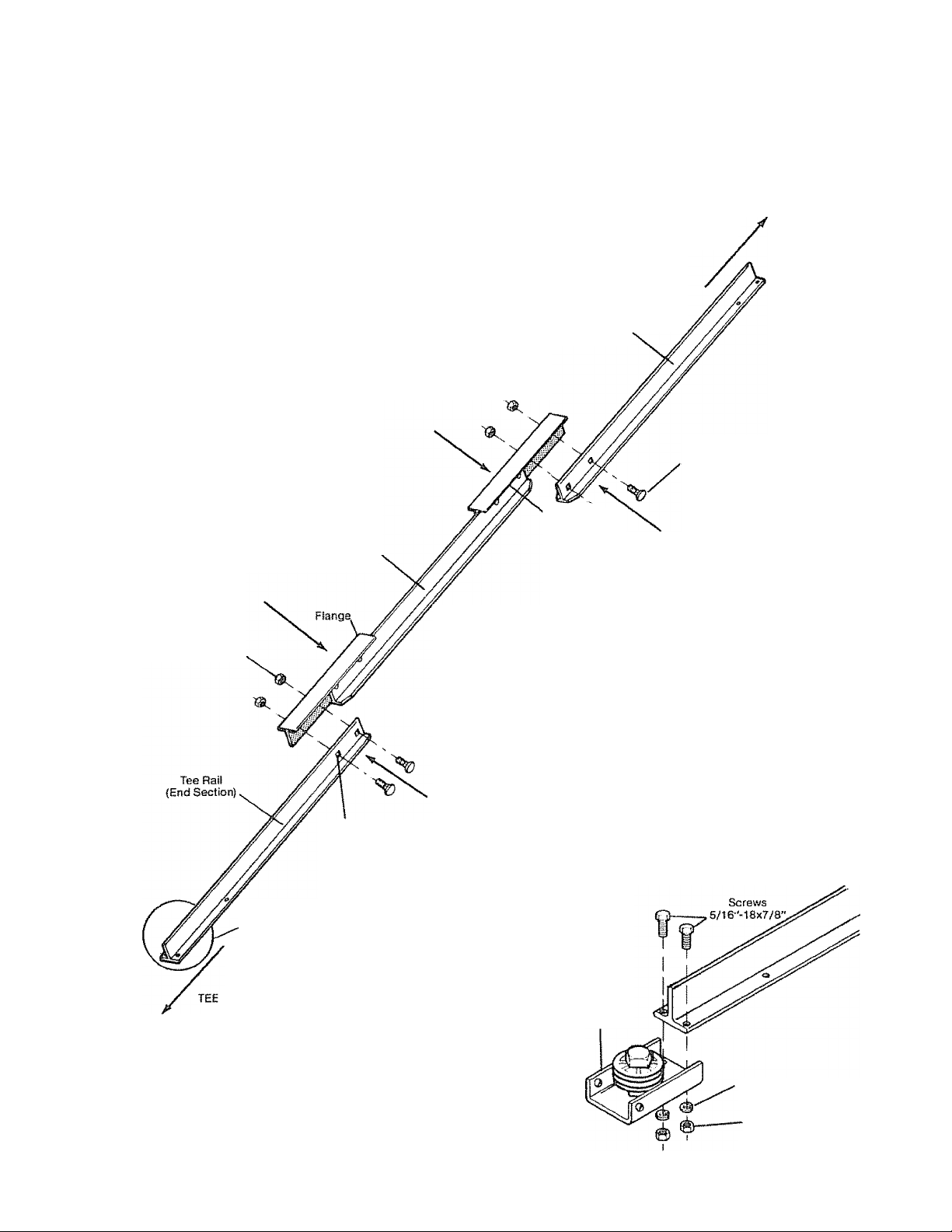
SXE P 1 Assemble Tee Rail & Attach Cable Pulley Bracket
TEE RAIL BACK
CTO CHASSIS)
CAUTION: Do not tighten the lock nuts until bolt
necks are seated in square holes.
Tee Rail
(End Seciiors)
Carriage Bolt
1/4"-20x1/2"
Flange
Tee Rail
(Center Section)
1 /4" Lock Nut
; RAIL FRONT
(TO DOOR)
Cable pulley bracket
. attaches to FRONT
END of Tee Rail
Square Carriage
Bolt Hole
PROCEDURE: Place the 3 Tee rail sections on a fiat
surface for assembly. THIS IS IM PORTANT. The center
section has two connection flanges The end sections
are identical.
Refer to illustration. BE SURE CENTER SECTION IS
POSITIONED ON THE CORRECT SIDE OF TEE
RAIL. (When assembled, Tee rail has a front-to-back
position as shown).
Bolt center rail section to end sections with the hard
ware illustrated.
SQUARE NECKS ON CARRIAGE BOLTS MUST BE
SEATED IN SQUARE HOLES IN TEE RAILS.
Cable Pulley
Bracket
Align front end of tee rail with cable pulley bracket and
connect as shown. Tighten screws and nuts securely.
Lock Washer
5/16"
Nut
5/16"
Page 7
Assembly
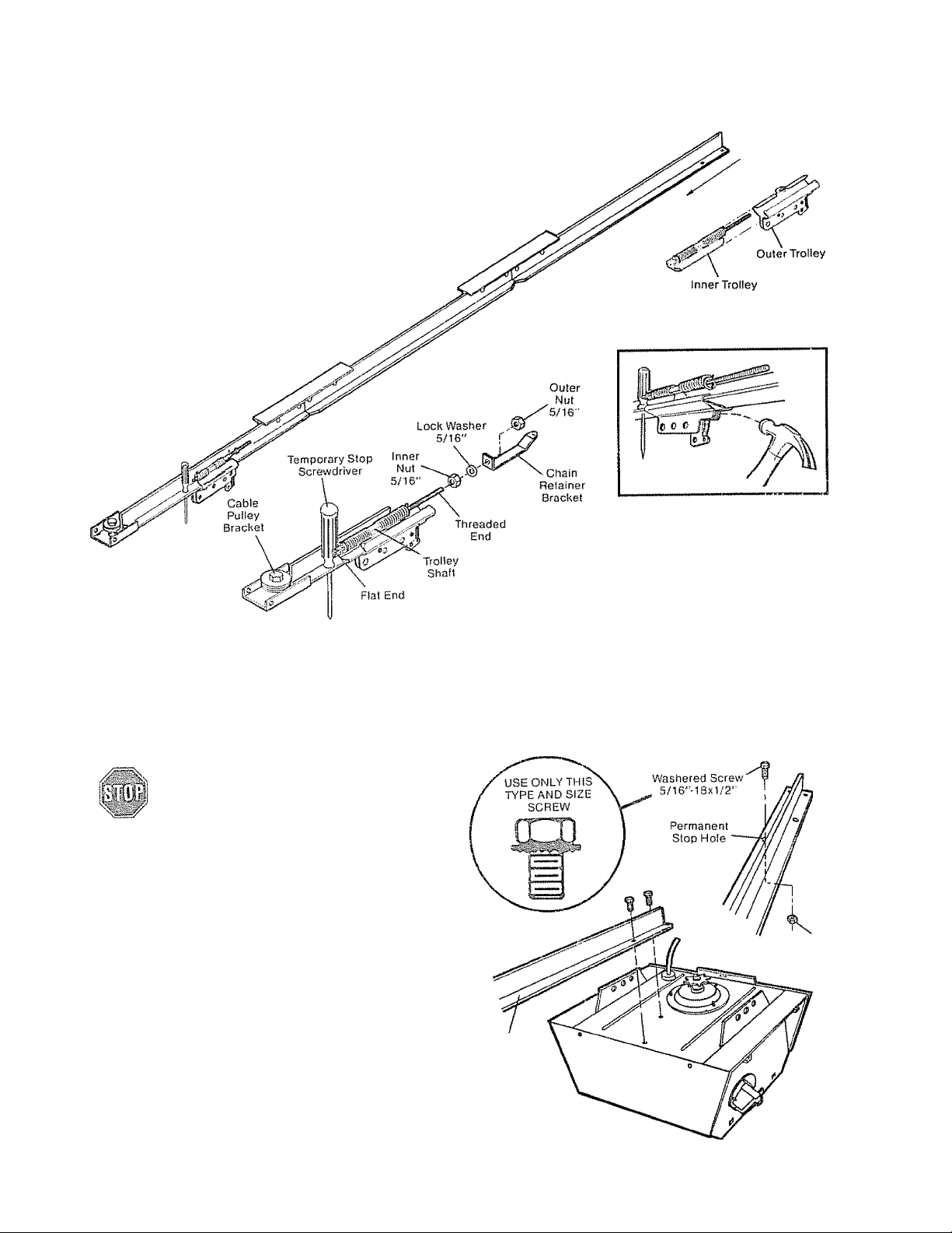
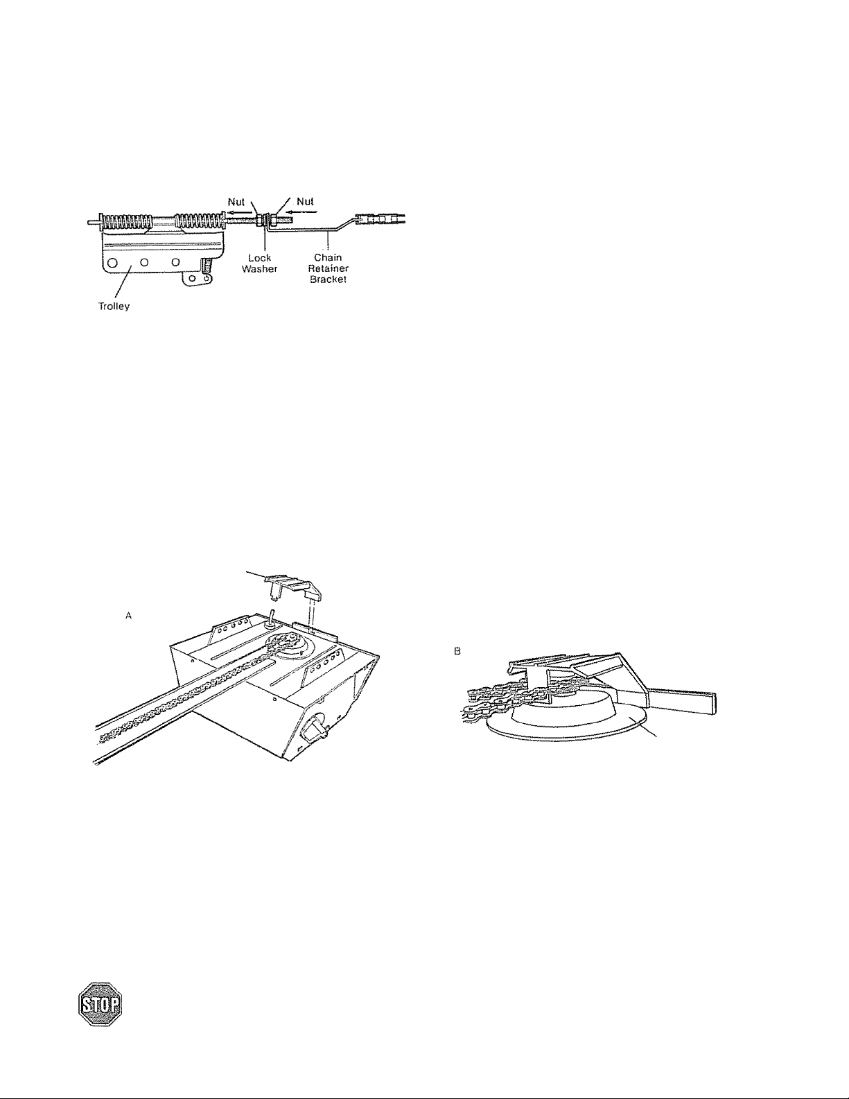
STEP 2 Connect Trolley & Attach Chain Retainer Bracket
Asa temporary stop, inserta screwdriver into Tee
rail as shown. Slide the inner trolley onto the Tee
rail, as shovi/n, until it is firmly against the screw
driver. Slide the outer trolley onto the Tee rail until it
partially engages the inner trolley and stops,
TO FULLY ENQAGE TROLLEY: With a hammer,
firmly tap the back end of outer trolley just below the
rail guide. Outer trolley must move forward to fully
engage inner trolley, Be careful to avoid damaging
trolley spring.
STEPS
USE ONLY THOSE SCREWS MOUNTED
INTOPOFOPENERCHASSIS. FAILURE
TO DO SO WILL CAUSE SERIOUS DAM
AGE TO THE DOOR OPENER,
PROCEDURE: Place opener chassis on packing
ma terial to protect cover. For convenience, place a
support under the cable pulley bracket.
Remove 5/16"-18x1/2" washered screws mounted
in top of opener chassis. Align holes in back end of
Tee rail with holes in opener chassis. Fasten the rail
to the chassis with washered screws previously
removed. CAUTION: USEONLYTHESESCRBWS!
Use of any other screws will cause serious dam
age to door opener. Tighten screws securely
Insert a 5/16”-18x1/2" washered screw into the per
manent stop hoie in the Tee rail back section as
shown. Tighten securely with a 5/16" nut
Attach Tee Rail to Opener Chassis
Attach inner nut, lock washer, chain retainer bracket
and outer nut to trolley shaft in the order shown. The
retainer bracket should be kept in the illustrated
position DO NOT TIGHTEN NUTS UNTIL STEP 5,
PAGE 9
5/16"-18
Tee Rail
(Back Section)
Nut
Page 8
Assembly
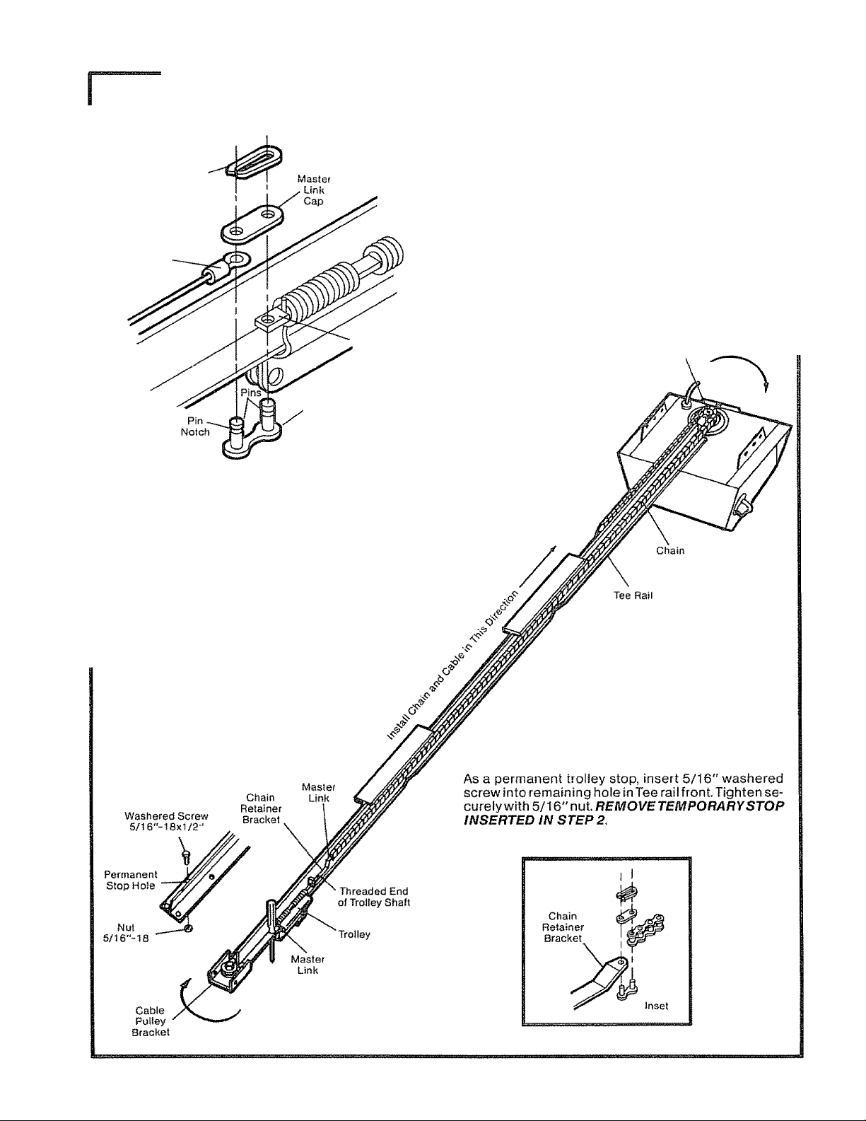
STEP 4 Install Chain and Cable
Master
Link
Clip-On
Spring
Cable
Loop
Flat End
Trolley
Shall
Ivl aster
Link
Outside
Bar
CAUTION: Keep chain taut while dispensing from
carton to help prevent kinking.
Slide trolley tight against screwdriver stop Dispense
cable around pulley bracket. Proceed back around
the opener sprocket and forward to chain retainer
bracket. Be sure teeth on chassis sprocket engage
chain.
Connect chain to chain retainer bracket, as shown in
inset, using second master link from coin envelope,
NOTE: Check to make sure chain is not twisted.
DO NOT REMOVE CHAIN AND CABLE FROM DIS-^
PENSER CARTON.
Detach cable from side of car ton and fasten to tr olley
with a master link from coin envelope,
MASTER LINK PROCEDURE: Push pins of master
link bar through loop of cable and hole in flat end of
trolley shaft Push cap onto pins and into notches
Slide clip-on spring over cap and into pin notches
until both pins are locked in place.
opener Chassis
Sprocket'
Page 9
Assembly
STEPS
Tighten the Chain and Cable
dAUTIONt Keep chain from twisting as nuts are
turned.
Loosen Tighten
Inner Outer
Chain
1/2 Inch
Base ot Tee Rail
PROCEDURE: Connect chain and cable to threaded
shaft of trolley in the order itiustrated: inner nut, lockwasher, chain retainer bracket and outer nut
Tighten the chain and cable by threading outer nut
toward trolley.
Chain is properly tightened when it is approximately
1/2" above the base of Tee rail midway between
cable pulley bracket and chassis.
When chain tension is correct, turn inner nut toward
chain retainer bracket untii tight
Sprocket noise can result if chain is either too
loose or too tight.
CAUTION: Do not overtighten chain and cable.
Refer to Page 21.
STEP® Attach Sprocket Cover to Opener Chassis
Sprocket
Cover '
ASSEMBLY OF YOUR GARAGE DOOR OPENER IS NOW COMPLETE.
CERTAIN INSTALLATION PROCEDURES VARY ACCORDING TO GARAGE DOOR TYPES. WHERE DIFFER
ENCES OCCUR, BE SURE TO FOLLOW ONLY THOSE INSTRUCTIONS WHICH APPLY TO YOUR DOOR
CONSTRUCTION.
PROCEDURE: Attach sprocket cover to chassis as
shown in Illustrations (A) and (B). insert back tab in
chassis slot. Then bend cover forward and insert
front tab in slot provided on mounting plate.
Mounting
Plate
DO NOT WEAR WATCHES, RINGS OR LOOSE CLOTHING WHILE INSTALLING OR SERVICING A DOOR OPENER.
KEEP GARAGE DOOR BALANCED. STICKING OR BINDING DOORS MUST SE REPAIRED. GARAGE DOORS,
DOOR SPRINGS, CABLES, PULLEYS, BRACKETS AND THEIR HARDWARE MAY BE UNDER EXTREME TEN
SION AND CAN CAUSE SERIOUS PERSONAL INJURY. DO NOT ATTEMPT ADJUSTMENTS. CALL A GARAGE
DOOR SERVICEMAN TO MOVE, LOOSEN OR ADJUST DOOR SPRINGS OR HARDWARE.
Page 10

Installation
Completed installations of header bracket, door bracket with plate and door arm (depending on door type) are shown
below,. The header bracket supports the front end of the Tee rail, The door bracket connects door arm to trolley,
IT IS RECOMMENDED THATTHE OPENER BE INSTALLED 7 FEETOR MORE ABOVE THE FLOOR WHERE SPACE
PERMITS. Follow only those instructions which apply to your door type as shown on Page 5.
STEP1
TO PREVENT DAMAGETO LIGHTWEIGHT GARAGE DOORS, ALWAYS REINFORCE THE INSIDEOFDOORBOTH VERTICALLY AND HORiZONTALLY-WITH 2x4 BOARDS OR ANGLE IRON.
Horizontal brace should be a! least 6 feet long Vertical brace should cover height of top panel. Reinforcement
hardware is not supplied (See No 1 Below.) FASTEN SECURELY AS SHOWN BEFORE INSTALLING DOOR
BRACKET AND PLATE
install Door Bracket and Plate
Sectional Door Installation Procedure
With door closed, locate and mark the vertical center
line of garage door. Extend line onto header wall
above door.
SECTIONAL DOOR
Door
Arm
Reinforcement
Board for
Lightweight Doors
1. Assemble door bracket and plate as shown Cen
ter bracket on vertical guideline (or up to one foot left
or right of center if necessary)
2. Position bracket assembly on face of door within
the following limits: A. Top edge of bracket 2" to 4"
below the top edge of door, B. Directly below any
structural support across top of door.
Placement depends on your particular needs
3. Mark and drill 5/16"TOP and BOTTOM fastening
holes. Secure bracket as shown
Carriage Bolt
5/i6'*-18x2-t/2
------------
Inside Edge
of Door or
Reinlofcement Board
Nut
5/16'-1S
Door Bracket
Plale
Lock
Washer
All One-Piece Door Installation Procedure
With door closed, locate and mark vertical center line
of door. Extend line onto header wall above door,
NOTE: The door bracket has left and right side
fastening holes. Assemble door bracket and plate
If your installation requires top and bottom fas
tening holes. (Refer to illustration).
Center bracket (with or without plate as required) on
top edge of door as shown Mark and drill two 5/16"
fastening holes and secure door bracket, NOTE; If
door has no exposed framing, drill 3/16" pilot
holes and substitute 5/16" x 1-1/2" lag screws
(not supplied) to fasten bracket to top of door.
Lock Washer
5/16"
NOTE: Door bracket may be installed on face of
door if required for your installation. (Refer to
dotted line drawing). HOWEVER, drill 3/16"pilot
holes and substitute 5/16" x 1-1/2" lag screws
(not supplied) to fasten bracket to door.
10
Header
Wall
Door Bracket
Plate
(Optional)
Page 11

Installation
THE HEADER BRACKET MUST BE RfGIDLY FASTENED TO THE HEADER WALL OR CElLtNG. REINFORCE
WALL OR CEILING WITH 2x4 IF NECESSARY.
STEP 2 Position & Install Header Bracket
Locate height for header bracket by opening door to
highest point of travel as shown. Draw a horizontal
line on header wall 2" above high point This height
provides travel clearance for top edge of door
When headroom is not sufficient for 2" clearance,
bottom edge of bracket may be placed parallel to the
high point of travel, or bracket may be attached to
ceiling
Optional Quick Turn Brackets are designed for low
headroom installations They replace top brackets
and rollers on the garage door, thereby lowering the
high point of door travel Installation instructions are
contained in the accessory carton
Position bracket as shown (bottom edge of bracket
on horizontal line), Mark either top and bottom or left
and right bracket holes Drill 3/16" pilot holes and
fasten bracket
Lag Screws
INSTALLATION
SECTIONAL DOOR AND
1-PIECE DOOR WITH TRACK
SECTIONAL DOOR
CURVED TRACK
^ Header
'( Bracket
Highest Point
of Travel
Door
Ceiling
Track
t
ONE-PIECE DOOR
HORIZONTAL TRACK
JAMB HARDWARE
INSTALLATION
1-PIECE DOOR WITHOUT TRACK
ONE-PIECE DOOR
NO TRACK
PIVOT HARDWARE
Header
k-l / Bracket
ONE-PIECE DOOR
NO TRACK
•JAMB HARDWARE
Highest Point
ol Travel
Locate height for header bracket by opening door to
highest point of travel as shown. Measure distance
from top of door to floor. Subtract actual height of
door Add 8" to the remainder See example below.
If the total number of inches exceeds the height
available in your garage, use the maximum height
possible On finished ceilings, do not position the
bracket closer than 1/2" from ceiling.
Measuring from top of door, draw a horizontal line on
the header wall at the determined height Position
bottom edge of header bracket on horizontal line,
centering bracket on vertical line. Mark either top
and bottom or left and right holes. Drill 3/16" pilot
holes and fasten with 5/16" x 1-7/8" lag screws as
shown above
EXAMPLE
0>
c
w Actual height of door -88"
Q
Distance from top of door (at
highest point of travel) to floor
Remainder
92"
Add + 8"
Bracket height on header wail =12"
''
4"
11
Page 12

Installation
STEPS
Attach Tee Rail to Header Bracket
PROCEDURE: Position opener chassis on garage
floor below door and header brackets. Use packing
material base to protect cover, iSiOTE: To enable
Tee rail to clear sectional door springs, it may be
necessary to lift the chassis onto a temporary
support.
CAUTION: Chassis must either be secured to sup
port or held firmly in place by another person.
Raise Tee rail until cable pulley and header brackets
come together, Align bracket holes and join with
clevis pin as shown. Insert and spread cotter pin to
secure.
STEP 4 Position Opener Chassis
TO PREVENT DAMAGE TO ALL LIGHTWEIGHT DOORS, AND DOORS WITH WINDOWS, DO NOT RESTTHE
OPENER ON THE DOOR.
SECTIONAL and ONE-PIECE
DOOR WITH TRACK
INSTALLATION
NOTE: A 2x4 Is convenient for setting an ideal
door-tO'Tee rail distance. It is not necessary
where headroom is insufficient.
PROCEDURE: Raise the opener chassis onto a
stepladder. Open the garage door. Place a 2x4 on
edge on top section of door directly above door
bracket. Rest Tee rail on 2x4,
ONE-PIECE DOOR
WITH NO - TRACK
INSTALLATION
PROCEDURE: Measure the distance from floor to
top of door (in fully open position and parallel to
floor).
Using a stepladder as a support, raise the opener
chassis to the same distance from the floor (chassis
will have a slight angle as shown)
The top of the door should be level with the top of the
opener For maximum efficiency, do not position the
opener chassis more than 2 inches above this point,
Top of Opener
12
Page 13

Installation
STEPS
Hang Opener Chassis
THE OPENER CHASSIS MUST BE ATTACHED TO A
STRUCTURAL SUPPORT OF THE GARAGE, Three
representative installations are shown. Yours may be
different Hanging brackets should be angled to pro
vide rigid support
PROCEDURE: On EACH side of opener measure
the distance from chassis to structural support
Cut both pieces of the hanging bracket to required
lengths. Flatten one end of each bracket and bend or
twist to fit fastening angles, DO NOT BEND AT BRAC
KET HOLES Drill 3/16" pilot holes in structural sup
port Fasten flattened ends of brackets to support
as shown.
Lift opener and fasten to hanging bracket as shown.
Checkto make sureTee rail is centered overdoor
bracket. Close the garage door. If door hits rail,
raise header bracket. REMOVE 2x4.
Grease rail surfaces on which trolley slides. A tube of
grease is supplied.
Bracket
(Not Supplied)
Finished
Ceiling
(Not Suppiied)
5/16'’-tax7/8" Screw
5/16" Lock Washer
5/16"-18 Nut
STEP 6
USE EMERGENCY RELEASE ONLY TO DIS
ENGAGE TROLLEY. DO NOT USE RED
EMERGENCY RELEASE ROPE AND HAN
DLE TO PULL DOOR OPEN OR CLOSED.
Attach Emergency Release Rope ^ Handle
PROCEDURE: Thread one end of rope through hole
in top of red handle so 'NOTICE' reads right side up
as shown. Secure with an overhand knot NOTE: Knot
should be at least 1 inch from end of rope to pre
vent slipping. Thread other end of rope through
hole in release arm of outer trolley. Adjust rope length
so that handle is 6 feet above the floor. Secure with
an overhand knot as above.
NOTE: If it is necessary to cut rope, heat seal cut
end with a match or lighter to prevent fraying
and/or raveling.
13
Emergency
Release Handle
Overhand
Knot
Page 14

Installation
Top
(astaliaHon
Flange
STEP?
Instali Wall Control
PROCEDURE: There are 4 screw terminals on the
back of the Wail Control, Connect the bell wire by
color; yellow to yellow, white to white, red to red and
black to black.
Fasten Wall Control to an Inside garage wall, as shown,
with the 8ABx1" sheet metal screws provided. A con
venient place is beside the service door and OUT OF
THE REACH OF CHILDREN,
Run the bell wire up the wall and across the ceiling to
the garage door opener. Use insulated staples.
Opener
Terminals
The receiver terminals as well as the antenna are
located on the right side pane! of the opener. Bend
antenna wire down until it is parallel to chassis panel.
Then connect the wire by color to the red, white,
black and yellow opener terminal screws.
INSTALL WALL CONTROL (OR ADDITIONAL
PUSH BUTTONS) OUTOFTHE REACH OFCHILDREN, DO NOT ALLOW CHILDREN TO OPER
ATE WALL CONTROL OR TRANSMITTER.
SERIOUS PERSONAL INJURY FROM A CLOS
ING GARAGE DOOR MAY RESULT FROM ANY
MISUSE OF OPENER.
FASTEN THE CAUTION LABEL ON THE WALL
NEAR THE WALL CONTROL AS A REMINDER
OF SAFE OPERATING PROCEDURES.
Flight Side
Panel
of
Opener
Wall Control
Push Button
Work Light
Push Button
WIRING INSTRUCTIONS FOR ACCESSORIES
Iftfrared Reversing System:
To white & black opener terminals
Open Door Indicator;
To white & orange opener terminals
Key Switch;
To red S white opener terminals
OPERATION OF WALL CONTROL
WALLCONTROLPUSH BUTTON
Press and release So open or close door
Press and release again So REVERSE door during CLOSING cycle
or to STOP door during OPENING cycle
VACATION PUSH BUTTON
Activate Vacation feature only when door is in ciosed position,
Press and release, Push button light will turn ON The Vacation fea
ture was designed to prevent operation of door Irom the transmitter
and allow door to travel in the UP direction ONLY Irom the Wall Con
trol push button (press and release) and Key Switch accessory
Press and release again. Push button light will turn OFF Opener will
return to normal operation
A power failure of more than 30 seconds will cause the vacation
feature to turn OFF
WORK LIGHT PUSH BUTTON
Press and release Opener light will turn on and remain on
Press and release again Opener light wilt return to normal operation.
14
Page 15

Installation
STEPS
TO AVOID SERIOUS PERSONAL INJURY FROM ENTANGLEMENT, REMOVE ALL ROPES CONNECTEDTO THE
GARAGE DOOR BEFORE OPERATING DOOR OPENER.
REMOVE EXISTING GARAGE DOOR LOCKS OR USE A WOOD SCREW OR NAIL TO MAKE THEM INOPERATIVE,
INSTALLATION AND WIRING MUST BE IN COMPLIANCE WITH LOCAL BUILDING AND ELECTRICAL CODES.
OPERATION AT OTHER THAN 120V 60Hz WILL CAUSE OPENER MALFUNCTION AND DAMAGE,
IF LOCAL ELECTRICAL CODES DO NOT REQUIRE
PERMANENT WIRING: Insert the 3-prong plug into a
3-hole receptacle. UNIT MUST BE GROUNDED, DO
NOT USE A 2-WIRE ADAPTER,
IF LOCAL CODES REQUIRE PERMANENT WIRING:
Refer to illustration,,
PROCEDURE: Make connection through 7/8 inch
diameter hole in top of opener chassis,
1. Remove opener chassis cover by removing the 4
cover screws,
2. Remove attached 3-prong cord,
3. Connect black (line) wire to black wire on terminal
block; white (neutral) wire to white terminal wire; green
(ground) wire to green ground screw
Coimect Eiectric Power
CAUTION: BE SURE UNIT IS GROUNDED
ACCORDING TO LOCAL CODE
STEPS
PROCEDURE; Install a 75 watt maximum light bulb
in each socket as shown. The lights turn on automati
cally when opener starts. After 4-1/2 minutes they
will turn off. Lights will REMAIN ON when Work Light
push button on Wall Control is pressed,
Install Lights and Lenses
IMPORTANT NOTE: If the lights in your garage
door opener do not work, it may NOT be the fault of
the opener. Some shorPneck bulbs, because of
their shape, do not make contact with the socket
base tab. Use standard-neck bulbs.
INSTALLING LENSES; Slide lenses into the lens
guides as shown. Snap bottom tabs into lens slots.
(The force and limit adjustment settings are located
on side panels behind lenses),
NOTE: FOR CONVENIENCE, LENSES MAYBE IN
STALLED AFTER ADJUSTMENT, STEPS, PAGE20.
15
Lens
Slot
Page 16

Installation
STEP 10
Connect Door Arm to Trolley
SECTIONAL DOOR INSTALLATION ONLY
PROCEDURE: Fasten straight door arm section to
trolley and wedge door arm section to door bracket,
as shown (A). Insert and spread a cotter pin to secur e
each connection,.
B
Bring the door arm sections together. Find a pair of
holes that line up and join sections as shown (B).
INSTALLATION FOR SECTIONAL DOOR IS COMPLETE. PROCEED TO ADJUSTMENT STEP 1, PAGE 18.
ALL ONE-PIECE DOOR INSTALLATIONS
ASSEMBLE DOOR ARM PROCEDURE: Fasten
straight and wedge door arm sections together to
their longest possible length. With dootclosed, con-,
nect straight door arm section to door bracket as
shown. Insert and spread cotter pin to secure.
16
Page 17

Installation
STEP 11
Adjust Limits (Ail One-Piece Doors Only}
CAUTION; To prevent damage to garage doors,
the opener limits must be adjusted on ALL ONEPIECE DOORS,
Limit Adjustment settings regulate the points at
which door will stop when moving up or down.
Repeated operation of theopenerduring adjustment
may cause the motor to overheat and shut off. Simply
wait 15 minutes and continue adjustments.
Limit adjustment screws are located on the left side
panel of the openeras shown. Increase limits by turn
ing screws in direction shown on label. Decrease
limits by turning screws in opposite direction.
Left Side
Panel UimiS
Adjustment
Screws
imii
iKßgwaosäL.si
iii®L?ilil '~r'. ‘ tifj>
■,
---
- -T- i J-
Adjustment Label
The following illustration shows the position of the door arm and trolley when the door is open (solid line drawing),
and when the door is closed (dotted line drawing)
PROCEDURE - OPEN DOOR ADJUSTMENT
DECREASE the UP limit by turning the UP limit adjust
ment screw counterclockwise 8 complete turns.
Press Wall Control push button. Trolley will travel to
full open position.
Manually raise garage door to open position (paral
lel to floor) and lift door arm to trolley. The arm should
touch trolley Just in back of door arm connector hole
as shown In solid line drawing If the arm does not
extend far enough, make further DECREASED limit
adjustment. One full turn equals 2 inches of door
PROCEDURE - CLOSED DOOR ADJUSTMENT
DECREASE the DOWN limit by turning the DOWN
limit adjustment screw clockwise 4 complete turns
Press Wall Control push button. Trolley will travel to
full closed position,
Manually close garage door and lift door arrh to the
trolley Arm should touch trolley just ahead of door
arm connector hole as shown in dotted line drawing.
If arm is behind the connector hole, make further
DECREASED limit adjustment. One full turn equals 2
inches of door travel.
travel,
CONNECT DOOR ARM TO TROLLEY PROCEDURE: With door closed,Join wedge door arm to connector hole in
trolley with the remaining clevis pin Secure with a cotter pin. NOTE: It may be necessary to lift door slightly to
make connection.
Run the opener through a complete travel cycle, If door has a slight ‘downward' slant in full open position, turn the
UP limit adjustment screw counterclockwise to decrease travel until door is parallel to floor.
17
Page 18

Adjustment
STEP1
The limit adjustment screws are located on the left side panel of the opener chassis as shown LI MIT ADJUSTMENT
settings regulate the points at which the door will stop when moving up or down
Adjust UP and DOWN Limits
NOTE: Door STOPS in UP direction if anything interferes with door travel. Door REVERSES in DOWN direc
tion if anything interferes with door travel (including binding or unbalanced doors).
PROCEDURE: To operate opener, press Wall Con
trol Push Button or transmitter push button. Run the
opener through a COMPLETE TRAVEL CYCLE. No
adjustments are needed when the door opens and
closes completely and does not reverse uninten
tionally in down direction.
The following char t outlines adjustment procedures.
Run opener through a COMPLETE TRAVEL CYCLE
AFTER EACH ADJUSTMENT. NOTE: REPEATED
OPERATION OFTHE OPEN ER DURING ADJUST
MENT PROCEDURES MAY CAUSE THE MOTOR
TO OVERHEATANDSHUTOFF. SIMPLYWA1T15
MINUTES AND TRY AGAIN. Read the chart care
fully before proceeding to Step 2, Pg. 19 Use a screw
driver to make limit adjustments
Adjustmen! Label
IF DOOR DOES NOT
OPEN COMPLETELY
BUT OPENS AT
LEAST FIVE FEET
IF DOOR DOES NOT
CLOSE COMPLETELY
IF DOOR REVERSES
WHEN CLOSING AND
THERE IS NO INTER-
FERENCETO
TRAVEL CYCLE
LliVilT ADJUSTMENT CHART
Increase UP travel by turning UP LIMIT adjustment screw in
clockwise direction as shown on label One turn equals 2
Inches of travel
If door doesn't open at least 5 feet, adjust OPEN FORCE as
explained in Step 2, Page 19
1. ON SECTIONAL DOORS:
Lengthen the door arm (See Step 10, Page 16).
If door arm is at maximum length, increase the DOWN travel
by turning the down limit adjustment screw in a counter
clockwise direction as shown on label. One turn equals 2
inches of travel.
If door still will not close completely, the header bracket is
positioned too high. Repeat Step 2, Page 11
2. ON ONE-PIECE DOORS:
Increase DOWN travel by turning the down limit adjustment
screw in a counterclockwise direction as shown on label. One
turn equals 2 inches of travel.
TEST DOOR FOR BINDING
Pull emergency release handle and manually open and close
the door. If door is binding, call a door ser viceman
1 . IF OPENER REVERSES BEFORE DOOR CLOSES FULLY:
Adjust the CLOSE FORCE as explained in Step 2, Page 19
2. IF OPENER REVERSES IN FULLY CLOSED POSITION;
Decrease DOWN travel. Tur n the down limit adjustment screw
in clockwise direction. One turn equals 2 Inches of travel
.............
.....................................................................................-
18
Page 19

Adjustment
STEP 2 Adjust Force
nn wrjT force ADJUSTMENTS TO COMPENSATE FOR A BINDING OR STICKING GARAGE DOOR.
iJcE^lil fStcE wfLUOTM OPERATION OFTHE SAFETY REVERSE SYSTEM
OR DAMAGE THE GARAGE DOOR.
Force Adjustment Controls are located on right side
panel of the opener chassis FORCE ADJUSTMENT
settings regulate the amount of power required to
open and close the door.
NOTE: Door STOPS In UP direction if anything
interferes with door travel. Door REVERSES in
DOWN direction if anything interferes with door
travel (including binding or unbalanced doors).
If force adjustments are set too light, door travel may
be interrupted by nuisance reversals in the DOWN
direction and stops in the UP direction As weather
conditions can affect door movement, occasional
adjustment may be needed
The maximum force adjustment range is 260 degrees,
about 3/4 of a complete turn. Do not force controls
beyond that point Turn force adjustment controls
with a screwdriver.
FORCE ADJUSTMENT CHART
Adjustment
Label
Force
■Adiustment
Controls
IF DOOR DOESN’T
OPEN AT LEAST 5 FT:
IF DOOR REVERSES
DURING THE DOWN
(CLOSE) CYCLE:
TEST DOWN
(CLOSE) FORCE:
Increase UP (OPEN) FORCE by turning control in a clock
wise direction as shown on label . Make 10 degree turn adjust
ments until door opens completely. Readjust UP LIMIT if
necessary. After each adjustment, run the opener through a
complete travel cycle.
Increase DOWN (CLOSE) FORCE by turning control in a
clockwise direction as shown on label, Make 10 degree turn
adjustments until door completes the close cycle. After each
adjustment, run opener through a complete travel cycle.
Grasp the door handle or door bottom when door is about
halfway through DOWN (CLOSE) TRAVEL. The door should
reverse If the door is hard to hold or doesn’t reverse, de
crease the DOWN (CLOSE) FORCE by turning the control in a
counter clockwise direction Make 10 degree turn adjust
ments until the door reverses normally. After each adjust
ment, run the opener through a complete travel cycle.
19
Page 20

Adjustment
STEFS
THE SAFETY REVERSE SYSTEM TEST IS IMPORTANT. THE GARAGE DOOR MUSTREVERSE ON CONTACT
WITH AONE INCH OBSTACLE PLACEDON THE FLOOR. FAILURETO PROPERLY ADJUSTTHE OPENER MAY
RESULT IN SERIOUS PERSONAL INJURY FROM ACLOSING GARAGE DOOR. REPEATTHE TEST AT LEAST
ONCE A YEAR AND MAKE ANY NEEDED ADJUSTMENTS,
PROCEDURE: Place a 1-inch obsiacle on the floor under the garage door. Operate the door in the DOWN
direction. The door must reverse on the obstruction.
If a SECTIONAL door STOPS on the obstruction,
lenghthen door arm (Step 10, Page 16) until the door
reverses in DOWN direction,.
If a ONE-PIECE door stops on obstruction, door is
not traveling far enough in DOWN direction. Increase
the DOWN limit by turning the DOWN limit adjust
ment screw counter-clockwise 1/4 turn REPEATTEST.
When the door reverses on the 1-inch obstruction,
remove obstruction and run opener through a com
plete travel cycle, Door must not reverse in closed
position, if it does, repeat Adjustment Steps 2 and 3.
Test Safety Reverse System
SECTIONAL DOOR
REPEAT ADJUSTMENT STEP 3 AFTER:
1. EACH ADJUSTMENT OF DOOR ARM LENGTH, CLOSE FORCE OR DOWN LIMIT
2. ANY REPAIR OR ADJUSTMENT OF THE GARAGE DOOR (INCLUDING SPRINGS AND HARDWARE)
3. ANY REPAIR OR BUCKLING OF THE GARAGE FLOOR
;
4,. ANY REPAIR OR ADJUSTMENT OF THE GARAGE DOOR OPENER
(Optional)
The INFRARED REVERSING SENSOR provides an
ADDITIONAL measure of safety against small child
ren being caughtunderagarage door, It uses an invis
ible beam which, when broken by an obstruction,
causes a closing door to open or prevents an open
door from closing
After the garage door opener has been completely
installed and adjusted, the INFRARED REVERSING
SENSOR accessory can be installed. Instructions are
included with this optional device
STEP 4
CAUTION: The Infrared Reversing Sensor will not
be in effect when Vacation Light is ON.
Install Infrared Reversing System
1/ ^'i'/ '^// "m ''^/Z ^^z
20
Page 21

Operation
CAUTION:
® START BY READING THE SAFETY RULES ON PAGE 3.
® READ THE OPERATING INSTRUCTIONS ON THIS PAGE CAREFULLY.
© DO NOT PERMIT CHILDREN TO PLA Y IN AREA OF DOOR.
© OPERATE ONLY WHEN OPENER IS PROPERLY ADJUSTED AND DOOR IS IN SIGHT AND FREE OF OBSTRUCTION.
THE SAFETY REVERSE SYSTEM IS IMPORTANT (SEE PAGE 20). GARAGE DOOR MUST REVERSE ON CON-
TACTWITHAONE-INCH OBSTACLE PLACEDONTHEFLOOR.FAILURETO PROPERLY ADJUSTOPENERMAY
RESULT IN SERIOUS PERSONAL INJURY FROM A CLOSING GARAGE DOOR. REPEATTHE TEST AT LEAST
ONCE A YEAR AND MAKE NEEDED ADJUSTMENTS.
USING THE OPENER
Your garage door opener can be activated by any of the following methods:
1. Pressing the transmitter push button, Hold the button down until door starts to move,
2. Pressing the Wall Control push buttons.
3. By turning the Key Switch (if you have installed this accessory).
WHEN EITHER THE WALL CONTROL OR TRANSWMTTER PUSH BUTTONS ARE PRESSED, ONE OF THE
FOLLOWING WILL OCCUR (Vacation Light OFF):
1. If open, the door wilt close. If closed, the door will open,
2. if closing, the door will reverse.
3. If opening, the door will stop (allowing space for entry and exit of pets and for fresh air).
4. If the door has been stopped in a partially open position (refer to 3. above), it will close.
5. If an obstruction is encountered while closing, the door wilt reverse.
6. If an obstruction is encountered while opening, the door will stop.
7. The optional Infrared Reversing Sensor, if instalied, will signal the opener to reverse the door in the closing cycle
when the IR beam is obstructed and prevent an open door from closing. It has no effect in the opening cycle.
of
Your Opener
THE LIGHTS
When the opener is activated, lights will turn on. They will turn off automatically after4-l/2 minutes. BULB SlZE-75
watts maximum. When Work Light is ON, the lights will remain on.
OPENING THE DOOR MANUALLY
The door can be operated manually by disconnecting it from the opener. Simply pul! down sharply on the red
emergency release handle. The door may now be lifted manually DO NOTUSE EMERGENCY ROPE AND HANDLE
TO PULL THE DOOR OPEN OR CLOSED. To automatically reconnect the door to the opener, press the Wall Control
push button
CARE OF THE OPENER
When properly installed, your opener will perform efficiently with a minimum of maintenance. You will be required to
replace a light bulb or change a transmitter battery from time to time. A 9-Volt Alkaline battery is the most reliable, and
is available at Sears.
The opener does not require additional lubrication - HOWEVER - the door rollers, bearings and hinges should be
oiled yearly.
Most complaints of unsatisfactory opener operation can be traced to problems with the door itself. The opener is not
intended to correct problems caused by an unbalanced or binding door, broken door springs orfaulty door hardware.
When operating the door manually, a properly balanced door will stay in any point of travel while being supported
soley by its springs, if you encounter any difficulty when operating door manually, call a garage door serviceman,
RADIO CONTROLS
Refer to pages 22 and 23 for complete details.
LIMIT AND FORCE ADJUSTMENTS
Refer to pages 18 and 19 for limit and force adjustments These adjustments must be checked and properly set when opener
is installed Weather conditions may cause minor changes in door operation requiring some change in adjustments,
particularly during the first year of operation. Only a screwdriver is required. Follow instructions carefully.
CHAIN TENSION ADJUSTMENT
After installation of opener and adjustment of forces and limits, chain may appear loose. This is normal. TO CHECK
CHAIN TENSION: disconnect the trolley by pulling red emergency handle. If chain returns to position described in
Step 5. Page 9, DO NOT make further adjustments.
21
Page 22

Radio Controls
RECEIVER
Right Side
Panel
Terminais
. Code
Swiich
Block
RADIO CONTROLS consist of a transmitter and a
receiver. The transmitter sends a coded signal from
outside the garage. The receiver is fastened to the
right side panel of the door opener, it receives the
transmitted signal and starts the door opener.
The signal code is set at the factory Page 23 des
cribes code changing procedures, if required.
Self service of radio controls is not recommended, if
service is needed, contact your nearest Sears Ser
vice Center.
THE TRANSMITTER
The portable transmitter may be secur ed to a car sun
visor with the clip provided Additional transmitters
can be purchased at any time for use in ali vehicles
using the garage, (Refer to Accessories, Page 5)„
New transmitters must be set to the same code as
original transmitter and receiver Foilow code set
ting procedures described on Page 23.
A 9-volt battery supplies the power The transmitter is
equipped with a battery check light When the trans
mitter push button is pressed, light will glow if battery
has power (and the opener will operate). When light
does not come on, replace battery. If transmission
range lessens, check battery light,
THE BATTERY
The battery should produce adequate po\«er for
approximately one year. Avoid the inconvenience of
unexpected battery failure by replacing it annualiy,
preferably before winter. Alkaline batteries are the
most reliable and are available at Sears.
TO REPLACE BATTERY: Remove visor dip and un
fasten connecting screw. Remove top of transmitter
case and discard old battery. Snap connector onto
new battery. Replace top of case and connecting
screw,. Replace visor clip
TRANSMITTER
Battery Tes
Light ■
22
Page 23

Radio Controls
Sears Trinary Radio Control
Manulactured under 1 or more oi Ure following li S. patents: 3 445 848: 3 906.348; and 4 037 201
The coded signal in Sears Trinary RadioControls can be changed easily without the aid of aserviceman.The only tool
needed Is a flat blade screwdriver Choose your own code by changing position of switches numbered 1 through 9 on
the receiver code switch block. Changing the position of only one switch makes an entirely different code.
MATCHING YOUR CODE IN A NEW TRANSMITTER
The original transmitter is preset at the factory to the same coded signal as the receiver. The code in any
NEW transmitters must be set to match the code In the original transmitter and the receiver.
PROCEDURE: With visor clip off, remove screw in
the original and new transmitter{s) as illustrated in
Figure 1. Carefully turn cades over (push button
sides up). Remove case tops as shown in Figure 2.
CAUTION: Be careful not to move circuit board
components.
Place transmitter circuit boards side by side as shown
in Figure 3, Set the code switches in the new trans
mitter to match those in the original transmitter. Use
a fingernail or screwdriver to slide the switches,.
Figure 3
E
-----------------
CHANGING YOUR CODE IN RECEIVER AND TRANSMITTER(S}
DISCONNECT POWER TO OPENER BEFORE CHANGING THE CODE IN THE RECEIVER.
The receiver is fastened to the right side panel of the
opener chassis. Code switches are shown in Figure 4.
IF YOUCHANGETHE CODE IN YOUR RECEIVER, ALSO
CHANGE THE CODE IN YOUR TRANSMITTER(S}.
PROCEDURE: Hold transmitter circuit board along
side recelvercode switches as shown To change the
code, use a fingernail or screwdriver. Slide one or
more receiver switches to a plus, minus or center
(0) position.
Set code switches in the transmitter(s) to match thé
new receiver code settings.
Code
Switch
Figure 1
-----------------------
5!||И1В!В r
-
V
Transmitter Circuit Board
RED WHT BLK
Hill HI Ü!@
:;i
Code Switches
Figure rt
1
c~~~n
•BiBiiîlîs c
Figure 2
щмицнитмццмшиии
ORN YEL
IMPORTANT NOTE: Code settings must be ex
actly the same in the receiver, transmitter and all
additional transmitters used to operate the door.
Please keep this instruction manual handy for
future reference.
23
h a 14 ъ:. 1 D 9
шеввееее
i-tf
Page 24

Having a Problem?
OPENER DOESN’T ACTIVATE
T Have you removed all door locks and bolts?
2 Does the opener have electric power? Check wall
switch, fuse, etc.
3. Is there a broken wire between Wall Control and
opener? Check under staples (A positive check
can be made by temporarily installing another wire)
4. Are wiring connections correct? Refer to Step 7,
Page 14.
5. Repeated operation may have tripped the over load
protector in the motor. Wait 15 minutes. Try again,
TRANSMITTER RANGE INSUFFICIENT
1. Check battery.
2 Change transmitter location in car
3. Metal garage door, foil-backed insulation or metal
siding will reduce range
4 Antenna on side panel of opener must be fully
extended downward.
DOOR DOESN’T OPEN OR CLOSE COMPLETELY
1, Is something obstructing the door?
2, Limits may need adjustment. See Pg. 18.
3., Force may need adjustment See Pg. 19
4 Door will not close while in Vacation mode.
DOOR OPENS AND CLOSES BY ITSELF
1 Neighbor with a Sears opener using the same code?
Change your code.
LIGHTS
1 Won’t turn OFF? Check Work Light Is it ON?
2. Won’t turn ON? Check light bulbs.
DOOR OPERATES FROM PUSH BUTTON BUT NOT
FROM TRANSMITTER
1. Replace the battery.
2 New transmitter? Have you set the code? Referto
Page 23..
3 Vacation light is ON.
DOOR REVERSES FOR NO APPARENT REASON
1 Pull red emergency release handle Operate the
door manually. Is it balanced? Binding? If service is
needed call a garage door serviceman
2 Force adjustment may be needed. See Pg 19
3 Check for proper alignment of Infrared Reversing
Sensor (if you have installed this accessory)..
4 Cleat ice and snow from gar age floor area where gar
age door closes.
THE NEED FOR OCCASIONAL ADJUSTMENT OF FORCE AND LIMIT CONTROLS IS NORMAL. WEATHER
CONDITIONS IN PARTICULAR CAN AFFECT DOOR MOVEMENT.
Transmitter
Schematic
24
Page 25

Wiring Diagram and Receiver Schematic
25
Page 26

INSTALLATION PARTS LIST
KEY
NO
1
2
3
4
5
6
7
8
9
10
11
PART
NO.
4102736
10A13
41A2830
29C121-2
41A2828
219A319
41A2829
12B374
12B3B0
178B32
178B33
NOT
41A2815
Wall control assy
9 volt battery (available at Sears!
Transmitter case, cover and screw assy
Transmitter visor dip
Emergency rope and handle assy
4-Strand bell wire
Header bracket plus colter pin and clevis
Door bracket
Door bracket piate
Wedge door arm section
Straight door arm section
SHOWN
Installation hardware bag (includes hardware illus
trated on Page 4)
-11
J
26
Page 27

Repair Parts
Chassis Assembly Parts List
KEY
PART
NO.
NO.
1 31C290
2 41A2827
3 41A2817
4
41B2S91
5 41C2725
41A3063
6
7 41A3073
KEY
DESCRIPTION
Sprockel cover
Gear and sprocket assy 9 108D30-1 Lens (each)
Complete with: 10 30B363
Spring washer 11 12A3T3
Thrust washer 12 1A2510
Retaining ring 13 41A2821 Motor assy, w/roli pin
Bearing plate
Roll pins (2)
Drive gear
Worm gear
Helical gear w/retainer 18 41A3027 Motor bracket and bearing assy.
Grease
Drive/worm gear kit w/grease
Roll pins(2i 21 41A3074 End panel
Line cord
Wire harness assy w/p!ug
Receiver logic board assy
Logic board
fcna pane! w/an lapeis
Light socket (1)
End pane! w/aii labels
PART
NO.
NO. DESCRIPTION
6 175888 Light socket (each)
Capacitor
Capacitor bracket
Terminal block w/screws
14
41C2740
15
41A2818
16
41D3013
17
41C3005
19
41A2826
41A2822 Interrupter cup assy
20
Cover w/ail labeis
Helicai gear and retainer w/grsase
Limit switch assy
RPM sensor assembly
Shaft bearing Kit
22 12B350 Hanging brackets
114AB95 Owners manual
41A2825 Chassis assy hardware kit (inctudes screws
not designated by number in illustration)
27
Page 28

Owners Manual
Al
ii VJ®
Garage
Door
Opener
Model
139.535006
V -r 3)-r’-y
i/ éü u\x ltJ Li ^
HOW TO ORDER REPAIR PARTS
Now that you have purchased your Sears Garage Door Opener, should a
need ever exist for repair parts or service, simply contact any Sears Service
Center and most Sears, Roebuck and Co, stores. Be sure to provide all
pertinent facts when you call or visit
The MODEL NUMBER of your garage door opener is printed on a label
located on the right side panel of the opener chassis.
Ail parts listed may be ordered from any service center and most Sears
stores.
WHEN ORDERING REPAIR PARTS, ALWAYS GIVE THE FOLLOWING
INFORMATION;
® PART NUMBER ® PART DESCRIPTION
® MODEL NUMBER ® NAME OF ITEM
If thé parts you need are not stocked locally, your order will be electroni
cally transmitted to a Sears Repair Parts Distribution Center for handling
IMPORTANT NOTE: If you suspect radio malfunction, contact your near
est SEARS Service Center
JMJtJlJ
MAINTENANCE AGREEMENTS ...YOUR WAY TO BUY TOMORROW’S SERVICE
TODAY’S PRICE ... With nationwide service and the benefits of a Sears warranty plus a Sears Mainte
nance Agreement, you don't have to worry about costly repairs resulting from normal use
The Maintenance Agreement does not cover installation or re-installation of the product or damage resulting from
external causes such as: acts of abuse, fire, flood, wind, lightning, freezing, etc.
To Purchase a Sears Maintenance Agreement - Ask Any Salesperson or Call Sears Service Today.
mIpHkSZÌSéIiiZ
SEARS WARRANTY
GARAGE DOOR OPENER MODEL 139.535006
FULL 90 DAY WARRANTY ON GARAGE DOOR OPENER
For 90 days from the date of purchase. Sears will repair this Garage Door Opener, free of charge, if defective in
material or workmanship.
From the 91st day until one year from the date of purchase, Sears will furnish replacement parts for any defective parts,
free of charge,. You pay for iabo
LIMITED WARRANTY ON MOTOR
After 1 year and through 5 years, if the motor on this Garage Door Opener is defective, Sears will furnish a replacement
motor, free of charge. You pay for labor.
Sears will not be liable for loss or damage to property or any incidental or consequential loss or
expense from property damage due directly or indirectly from the use of this product.
Some states do not allow the exclusion or limitation of incidental or consequential damages, so the above limitation or
exclusion may not apply to you
This warranty does not cover repairs necessary because of operator abuse or negligence, including the failure to install,
adjust and operate this garage door opener according to the instructions contained in the owner’s manual,
WARRANTY SERVICE iS AVAILABLE BY SIMPLY CONTACTING THE NEAREST SEARS SERVICE CENTER/DEPABTMENT IN THE UNITED STATES. This warranty applies only while the product is in use in the United States.
This warranty gives you specific legal rights, and you may also have other rights which vary from state to state
LIMITED WARRANTY
LIMITATION ON LIABILITY
114A895
SEARS ROEBUCK AND COMPANY, Dept 698/731 A, Sears Tower, Chicago, IL 60684
ÖSZ
zsz 'ZSDSZ
■Z3XZ
Printed in Mexico
 Loading...