

Page 1
1/2 HP
GARAGE DOOR OPENER
For Residential Use Only
Models • 139.18595
Read and follow all safety rules
and operating instructions before
first use of this product.
Fasten the manual near the garage
door after installation.
Periodic checks of the opener are
required to ensure safe operation.
Owner’s Manual
ENGLISH
Sears Canada, Inc., Toronto, Ontario M5B 2B8
■ Safety Precautions
■ Assembly
■ Installation
■ Adjustment
■ Maintenance
■ Operation
■ Troubleshooting
■ Parts List
®
Page 2
2
TABLE OF CONTENTS
When you see these Safety Symbols and Signal
Words on the following pages, they will alert you to
the possibility of serious injury or death if you do
not comply with the warnings that accompany them.
The hazard may come from something mechanical
or from electric shock. Read the warnings carefully.
When you see this Signal Word on the following
pages, it will alert you to the possibility of damage to
your garage door and/or the garage door opener if
you do not comply with the cautionary statements
that accompany it. Read them carefully.
INTRODUCTION
Safety Symbol and Signal Word Review
This garage door opener has been designed and tested to offer safe service provided it is installed, operated,
maintained and tested in strict accordance with the instructions and warnings contained in this manual.
Mechanical
Electrical
WARNING
WARNING
WARNING
WARNING
Introduction 2-7
Safety symbol and signal word review........................2
Preparing your garage door ........................................3
Tools needed...............................................................3
Planning ..................................................................4-5
Carton inventory..........................................................6
Hardware inventory .....................................................7
Assembly 8-11
Assemble the rail and install the trolley ......................8
Fasten the rail to the motor unit and
install the idler pulley...................................................9
Install the chain/cable................................................10
Tighten the chain.......................................................11
Installation 11-26
Installation safety instructions....................................11
Determine the header bracket location .....................12
Install the header bracket..........................................13
Attach the rail to the header bracket.........................14
Position the opener ...................................................15
Hang the opener .......................................................16
Install the door control...............................................17
Install the lights .........................................................18
Attach the emergency release rope and handle .......18
Electrical requirements..............................................19
Install The Protector System®..............................20-22
Fasten the door bracket.......................................23-24
Connect the door arm to the trolley .....................25-26
Adjustment 27-29
Adjust the travel limits ...............................................27
Adjust the force .........................................................28
Test the safety reversal system.................................29
Test The Protector System®......................................29
Operation 30-34
Operation safety instructions.....................................30
Using your garage door opener ................................30
Using the wall-mounted Door Control .......................31
To open the door manually........................................31
Care of your garage door opener..............................32
Having a problem? ....................................................33
Diagnostic chart.........................................................34
Programming 35-36
To add or reprogram a hand-held remote control .....35
To erase all codes .....................................................35
3-Function Remotes..................................................35
To add, reprogram or change
a Keyless Entry PIN ..................................................36
Repair Parts 37-38
Rail assembly parts...................................................37
Installation parts ........................................................37
Motor unit assembly parts.........................................38
Accessories 39
Warranty 39
Repair Parts and Service 40
WARNING
WARNING
CAUTION
Page 3
3
To prevent damage to garage door and opener:
• ALWAYS disable locks BEFORE installing and operating
the opener.
• ONLY operate garage door opener at 120V, 60 Hz to
avoid malfunction and damage.
To prevent possible SERIOUS INJURY or DEATH:
• ALWAYS call a trained door systems technician if
garage door binds, sticks, or is out of balance. An
unbalanced garage door may not reverse when
required.
• NEVER try to loosen, move or adjust garage door, door
springs, cables, pulleys, brackets or their hardware, all
of which are under EXTREME tension.
• Disable ALL locks and remove ALL ropes connected to
garage door BEFORE installing and operating garage
door opener to avoid entanglement.
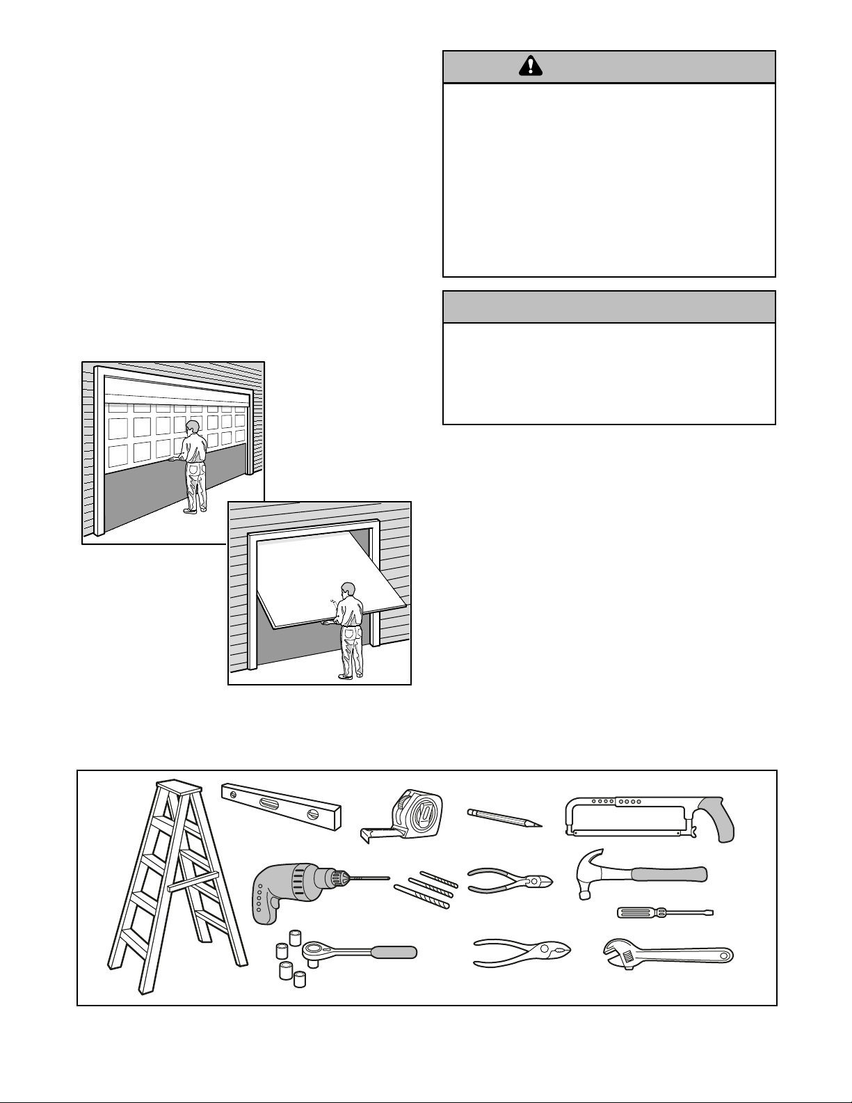
Preparing your garage door
Before you begin:
• Disable locks.
• Remove any ropes connected to garage door.
• Complete the following test to make sure your
garage door is balanced and is not sticking or
binding:
1. Lift the door about halfway as shown. Release
the door. If balanced, it should stay in place,
supported entirely by its springs.
2. Raise and lower the door to see if there is any
binding or sticking.
If your door binds, sticks, or is out of balance, call a
trained door systems technician.
Tools needed
During assembly, installation and adjustment of the
opener, instructions will call for hand tools as
illustrated below.
WARNING
WARNING
WARNING
WARNING
Sectional Door
One-Piece Door
WARNING
CAUTION
Carpenter's
Level (optional)
Drill
2
1
Tape Measure
Drill Bits
3/16", 5/16"
and 5/32"
Pencil
Hack Saw
Claw Hammer
Wire Cutters
Screwdriver
Stepladder
Sockets and Wrench
1/2", 5/8", 7/16", 9/16"
and 1/4"
Pliers
Adjustable End Wrench
Page 4
4
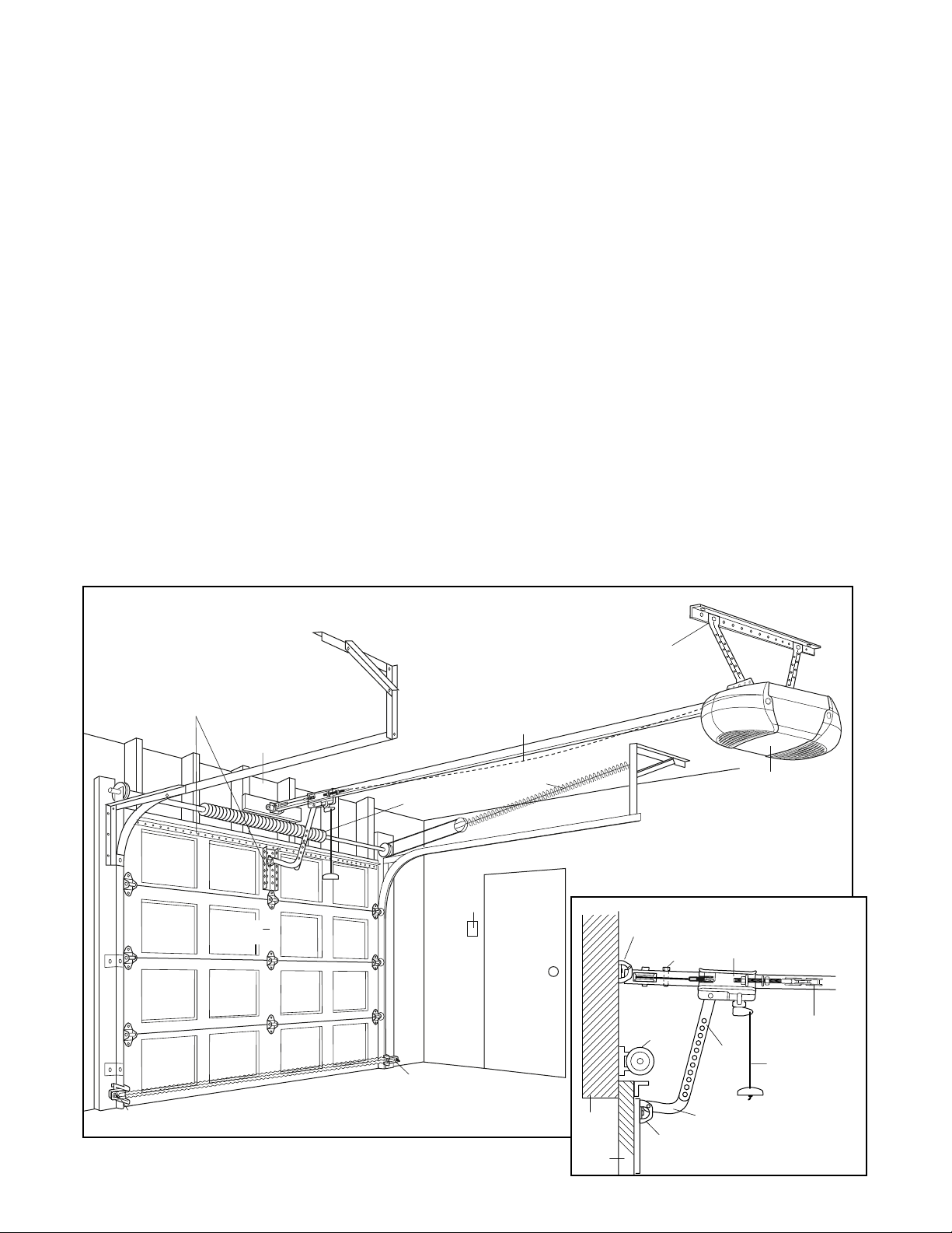
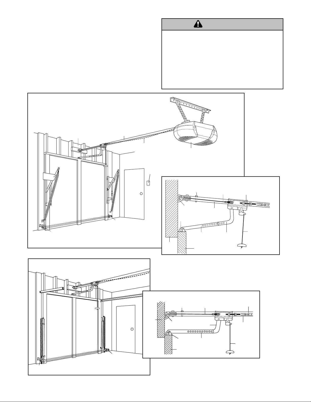
SECTIONAL DOOR INSTALLATION
Planning
Identify the type and height of your garage door.
Survey your garage area to see if any of the
conditions below apply to your installation. Additional
materials may be required. You may find it helpful to
refer back to this page and the accompanying
illustrations as you proceed with the installation of
your opener.
Depending on your requirements, there are several
installation steps which may call for materials or
hardware not included in the carton.
• Installation Step 1 – Look at the wall or ceiling
above the garage door. The header bracket must
be securely fastened to structural supports.
• Installation Step 5 – Do you have a finished ceiling
in your garage? If so, a support bracket and
additional fastening hardware may be required.
• Installation Step 10 – Depending upon garage
construction, extension brackets or wood blocks
may be needed to install sensors.
• Installation Step 10 – Alternate floor mounting of
the safety reversing sensor will require hardware
not provided.
• Do you have an access door in addition to the
garage door? If not, Model 18752 Emergency Key
Release is required. See Accessories page.
• Look at the garage door where it meets the floor.
Any gap between the floor and the bottom of the
door must not exceed 1/4" (6 mm). Otherwise, the
safety reversal system may not work properly. See
Adjustment Step 3. Floor or door should be
repaired.
SECTIONAL DOOR INSTALLATIONS
• Do you have a steel, aluminum, fiberglass or glass
panel door? If so, horizontal and vertical
reinforcement is required (Installation Step 11).
• The opener should be installed above the center of
the door. If there is a torsion spring or center
bearing plate in the way of the header bracket, it
may be installed within 4 feet (1.22 m) to the left or
right of the door center. See Installation Steps 1
and 11.
• If your door is more than 7 feet (2.13 m) high, see
rail extension kits listed on Accessories page.
Horizontal and vertical reinforcement
is needed for lightweight garage doors
(fiberglass, steel, aluminum, door with
glass panels, etc.). See page 23 for details.
Header Wall
Vertical
Centerline
of Garage
Door
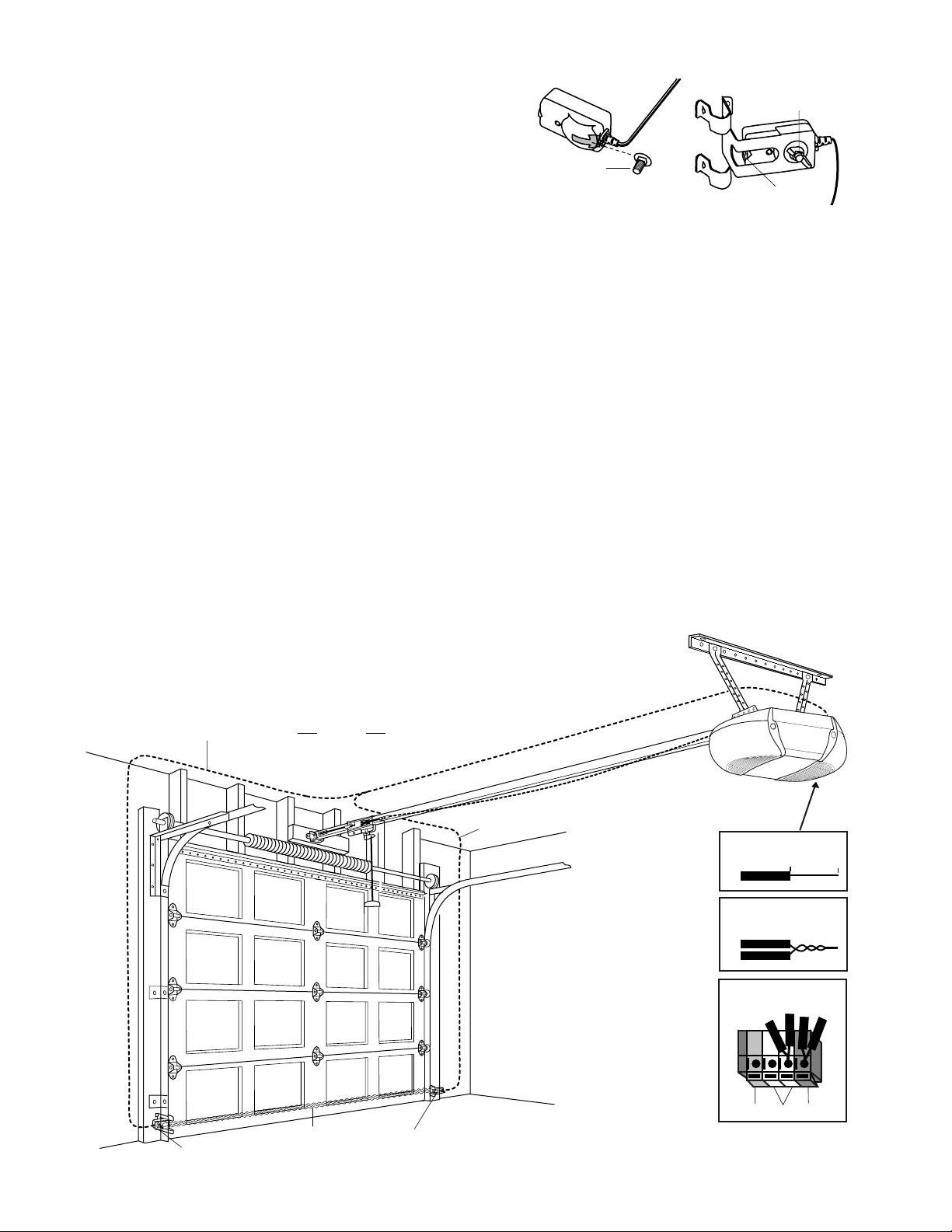
Safety Reversing Sensor
— — — — — — — —
Gap between floor
and bottom of door
must not exceed 1/4" (6 mm).
Slack in chain tension
is normal when
garage door is closed.
Torsion Spring
Wallmounted
Door
Control
Safety Reversing
Sensor
Extension Spring
OR
Access Door
FINISHED CEILING
Support bracket &
fastening hardware
is required.
See page 16.
Header
Bracket
Garage
Door
Spring
Header
Wall
Garage
Door
Trolley
Stop Bolt
Door
Bracket
CLOSED POSITION
Trolley
Straight
Door
Arm
Curved
Door
Arm
Motor unit
Chain
Emergency
Release
Rope & Handle
Page 5
5
Planning (Continued)
ONE-PIECE DOOR INSTALLATIONS
• Generally, a one-piece door does not require
reinforcement. If your door is lightweight, refer to
the information relating to sectional doors in
Installation Step 11.
• Depending on your door’s construction, you may
need additional mounting hardware for the door
bracket (Step 11).
ONE-PIECE DOOR WITHOUT TRACK
Without a properly working safety reversal system,
persons (particularly small children) could be
SERIOUSLY INJURED or KILLED by a closing garage
door.
• The gap between the bottom of the garage door and
the floor MUST NOT exceed 1/4" (6 mm). Otherwise,
the safety reversal system may not work properly.
• The floor or the garage door MUST be repaired to
eliminate the gap.
WARNING
ONE-PIECE DOOR WITH TRACK
WARNING
Header Wall
Safety Reversing
Sensor
Safety Reversing Sensor
Gap between floor
and bottom of door must not exceed 1/4" (6 mm).
FINISHED CEILING
Support bracket
& fastening
hardw
See page 16.
Rail
Access
Door
are is
required.
Slack in chain tension
is normal when garage
door is closed.
Wall-mounted
Door Control
Header
Wall
Motor Unit
Trolley Stop Bolt
Header
Bracket
Door Bracket
Straight
Door
Arm
Garage Door
CLOSED POSITION
Cable
Rail
Curved
Door
Arm
Trolley
Emergency
Release
Rope & Handle
Gap between floor
Safety
Reversing Sensor
and bottom of door
must not exceed 1/4" (6 mm).
Access
Door
Safety
Reversing
Sensor
Header
Wall
CLOSED POSITION
Trolley Stop Bolt
Header
Bracket
Door
Bracket
Garage
Door
Cable
Curved
Door Arm
Straight
Door
Arm
Chain
Rail
Emergency
Release
Rope &
Handle
Page 6
6
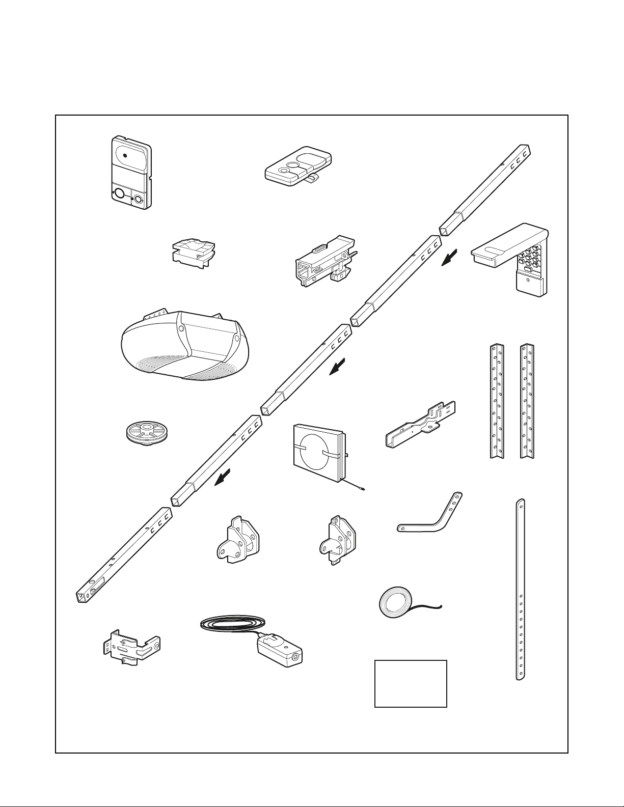
Your garage door opener is packaged in one carton
which contains the motor unit and all parts illustrated
below. Accessories will depend on the model
purchased. If anything is missing, carefully check the
packing material. Parts may be stuck in the foam.
Hardware for assembly and installation is shown on
the next page. Save the carton and packing material
until installation and adjustment is complete.
Carton Inventory
L
I
G
H
T
L
O
C
K
Premium Control Console
Chain Spreader
SECURITY✚
3-Function Remote Control (2)
®
Trolley
Rail
Center/Back
Sections
SECURITY✚
Keyless Entry
®
Rail
Front (header)
Section
Safety Sensor
Bracket (2)
Motor Unit with 2 Light Lenses
Idler Pulley
(2) Safety Reversing Sensors
(1 Sending Eye and 1 Receiving Eye)
with 2-Conductor White & White/Black
Bell Wire attached
Header Bracket
Chain and Cable
Door Bracket
"U" Bracket
Curved Door
Arm Section
2-Conductor Bell Wire
White & White/Red
Safety Labels
and
Literature
Hanging Brackets
Straight Door
Arm Section
Page 7
7
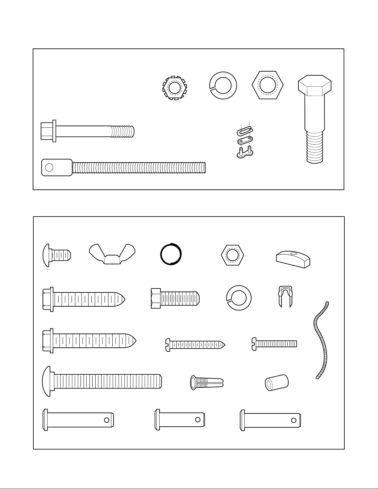
Hardware Inventory
Separate all hardware and group as shown below for the assembly and installation procedures.
ASSEMBLY HARDWARE
INSTALLATION HARDWARE
Bolt 1/4"-20x1-3/4" (2)
Carriage Bolt
1/4"-20x1/2" (2)
Trolley Threaded Shaft (1)
Wing Nut
1/4"-20 (2)
Lock Nut
1/4"-20 (2)
Lock Washer
3/8" (1)
Ring
Fastener (3)
Nut 5/16"-18 (8)
Master
Link (2)
Nut
3/8" (1)
Idler Bolt (1)
Handle
Lag Screw
5/16"-9x1-5/8" (2)
Lag Screw
5/16"-18x1-7/8" (2)
Carriage Bolt
5/16"-18x2-1/2" (2)
Clevis Pin
5/16"x1-1/2" (1)
Hex Bolt
5/16"-18x7/8" (4)
Screw
6ABx1-1/4" (2)
Clevis Pin
5/16"x1" (1)
Lock Washer 5/16" (7)
Drywall Anchors (2)
Insulated
Staples (30)
Screw 6-32x1" (2)
Rope
Spacer (2)
Clevis Pin
5/16"x1-1/4" (1)
Page 8
8
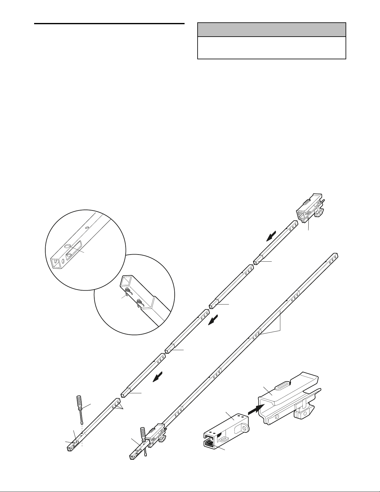
ASSEMBLY STEP 1
Assemble the Rail & Install the Trolley
To avoid installation difficulties, do not run the
garage door opener until instructed to do so.
To prevent INJURY from pinching, keep hands and
fingers away from the joints while assembling the rail.
WARNING
WARNING
WARNING
The front rail has a cut out “window” at the door end
(see illustration). The hole above this window is
larger on the top of the rail than on the bottom. A
smaller hole 3-1/2" (8.9 cm) away is close to the rail
edge. Rotate the back rail so it has a similar hole
close to the opposite edge, about 4-3/4" (12 cm)
from the far end. NOTE: Using the sequence above
the clips will be facing down.
1. Remove the straight door arm and hanging
bracket packaged inside the front rail and set
aside for Installation Step 5 and 12. NOTE: To
prevent INJURY while unpacking the rail carefully
remove the straight door arm stored within the rail
section.
2. Align the rail sections on a flat surface as shown
and slide the tapered ends into the larger ones.
Tabs along the side will lock into place.
NOTE: Rail sections may be assembled with the
clips up or down (down is preferred) disassembly of
rail may damage clips.
3. Place the motor unit on packing material to protect
the cover, and rest the back end of the rail on top.
For convenience, put a support under the front
end of the rail.
4. As a temporary trolley stop, insert a screwdriver
into the hole 10" (25 cm) away from the front of
the rail, as shown.
5. Check to be sure there are 4 plastic wear pads
inside the inner trolley. If they became loose
during shipping, check all packing material. Snap
them back into position as shown.
6. Slide the trolley assembly along the rail from the
back end to the screwdriver.
CAUTION
Trolley
Idler
Pulley
Hole
Window
Cut-Out
KEEP LARGER
HOLE ON TOP
FRONT RAIL
(TOP)
Screwdriver
Clip
Tapered
End of
Rail
Tabs
Front Rail
(TO DOOR)
Tapered
End
Tapered
End
Tapered
End
Inner Trolley
Wear Pads
Outer Trolley
Tapered
End
Back Rails
(TO MOTOR UNIT)
Page 9
9
To avoid SERIOUS damage to garage door opener,
use ONLY those bolts/fasteners mounted in the top of
the opener.
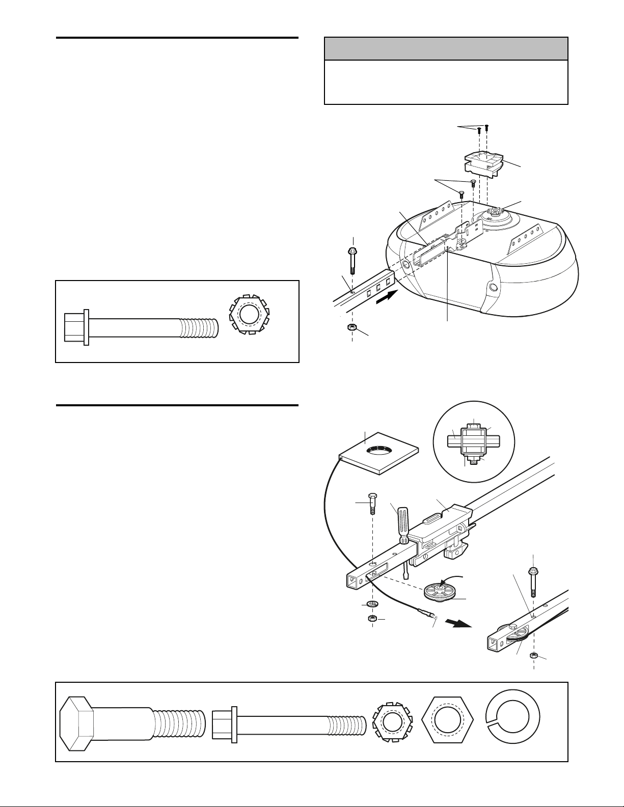
ASSEMBLY STEP 2
Fasten the Rail to the Motor Unit
• Insert a 1/4"-20x1-3/4 bolt into the cover protection
bolt hole on the back end of the rail as shown.
Tighten securely with a 1/4"-20 lock nut. Do NOT
overtighten.
• Remove the two bolts from the top of the motor
unit.
• Place the “U” bracket, flat side down onto the
motor unit and align the bracket hole with the bolt
holes. Fasten with the previously removed bolts.
• Align the rail assembly with the top of the motor
unit. Slide the rail end onto the “U” bracket, all the
way to the stops that protrude on the top and sides
of the bracket.
• Attach spreader to the motor unit with two screws.
ASSEMBLY STEP 3
Install the Idler Pulley
• Lay the chain/cable beside the rail, as shown.
Grasp the end of the cable and pass
approximately 12" (30 cm) of cable through the
window. Allow it to hang until Assembly Step 5.
• Remove the tape from the idler pulley. The inside
center should be pre-greased. If dry, regrease to
ensure proper operation.
• Place the idler pulley into the window as shown.
• Insert the idler bolt from the top through the rail
and pulley. Tighten with a 3/8" lock washer and nut
underneath the rail until the lock washer is
compressed.
• Rotate the pulley to be sure it spins freely.
• Insert a 1/4"-20x1-3/4 bolt into the trolley stop hole
in the front of the rail as shown. Tighten securely
with a 1/4"-20 lock nut.
WARNING
WARNING
WARNING
HARDWARE SHOWN ACTUAL SIZE
"
HARDWARE SHOWN ACTUAL SIZE
Lock Nut
Bolt 1/4"-20x1-3/4"
1/4"-20
CAUTION
Hex Screws
8-32x7/16"
Bolts
"U" Bracket
Bolt
Cover
Protection
Bolt Hole
SLIDE RAIL TO STOPS
Lock Nut
ON TOP AND SIDES
OF BRACKET
Chain
Spreader
Motor Unit
Sprocket
Chain and
Cable
Idler
Bolt
Lock
Washer
3/8"
Screwdriver
Nut 3/8"
Trolley
Cable Link
Pulley
Washer
Bolt
Rail
Nut
Trolley
Stop Hole
Grease
Inside Pulley
Idler
Pulley
Idler
Pulley
Bolt
Lock
Nut
Idler Bolt
Bolt 1/4"-20x1-3/4"
Lock Nut 1/4"-20
Nut 3/8"
Lock Washer 3/8
Page 10
10
To avoid possible SERIOUS INJURY to fingers from
moving garage door opener:
• ALWAYS keep hand clear of sprocket while operating
opener.
• Securely attach chain spreader BEFORE operating.
Leave Chain and Cable
Inside Dispensing
Carton to Prevent Kinking.
Dispensing Carton
Keep Chain and Cable
Taut When Dispensing
WARNING
Figure 1
Figure 2
Figure 3
Figure 4
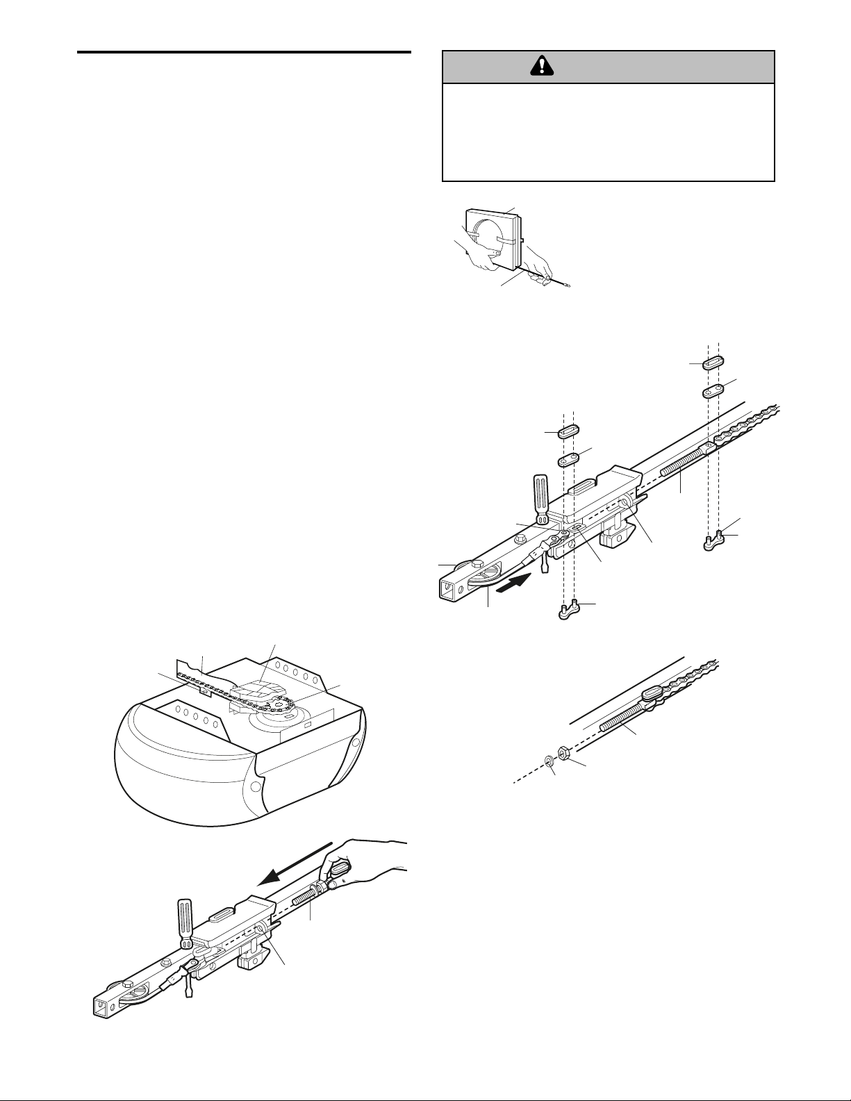
ASSEMBLY STEP 4
Install the Chain/Cable
1. Pull the cable around the idler pulley and toward
the trolley.
2. Connect the cable to the retaining slot on the
trolley, as shown (Figure 1):
• From below, push pins of master link bar up
through cable link and trolley slot.
• Push master link cap over pins and past pin
notches.
• Slide clip-on spring over cap and onto pin
notches until both pins are securely locked in
place.
3. With the trolley against the screwdriver, dispense
the remainder of the cable/chain along the rail
toward the motor unit into the slot on the chain
spreader, around the sprocket onto the chain
spreader and continuing to the trolley assembly.
The sprocket teeth must engage the chain
(Figure 2).
4. Check to make sure the chain is not twisted, then
connect it to the threaded shaft with the remaining
master link.
5. Thread the inner nut and lock washer onto the
trolley threaded shaft (Figure 3).
6. Insert the trolley threaded shaft through the hole in
the trolley. Be sure the chain is not twisted
(Figure 4).
7. Loosely thread the outer nut onto the trolley
threaded shaft.
8. Remove the screwdriver.
Chain
"U" Bracket
Bolt
Spreader
Motor Unit
Sprocket
WARNING
Master Link
Clip-On Spring
Master Link
Idler
Pulley
Clip-On Spring
Cable
Link
Cable
Master
Link Cap
Slotted
Hole
Master
Link Bar
Trolley
Threaded
Shaft
Round
Hole
Master
Link Cap
Pin
Notch
Master
Link Bar
Round
Hole
Trolley
Threaded
Shaft
Inner Nut
5/16"
Lock
Washer
5/16"
Trolley
Threaded
Shaft
Page 11
11
INSTALLATION
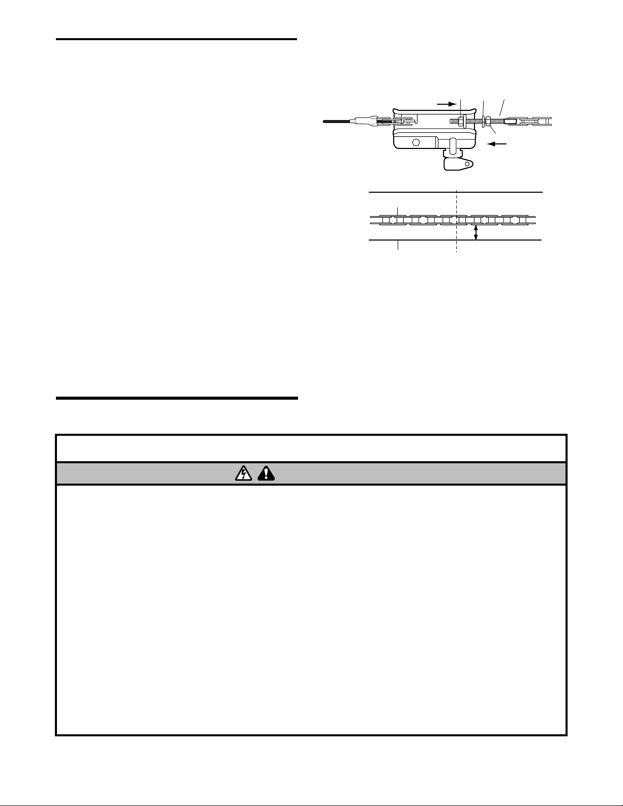
ASSEMBLY STEP 5
Tighten the Chain
• Spin the inner nut and lock washer down the
trolley threaded shaft, away from the trolley.
• To tighten the chain, turn outer nut in the direction
shown (Figure 1).
• When the chain is approximately 1/4" (6 mm)
above the base of the rail at its midpoint, re-tighten
the inner nut to secure the adjustment.
Sprocket noise can result if chain is too loose.
When installation is complete, you may notice some
chain droop with the door closed. This is normal. If
the chain returns to the position shown in Figure 2
when the door is open, do not re-adjust the chain.
NOTE: During future maintenance, ALWAYS pull the
emergency release handle to disconnect trolley
before adjusting chain.
NOTE: You may notice loosening of chain after
Adjustment Step 3 (Test the Safety Reversal
System). Check for proper tension and readjust
chain if necessary. Then repeat Adjustment Step 3.
You have now finished assembling your garage
door opener. Please read the following warnings
before proceeding to the installation section.
Figure 1
Figure 2
IMPORTANT INSTALLATION INSTRUCTIONS
To reduce the risk of SEVERE INJURY or DEATH:
WARNING
WARNING
1. READ AND FOLLOW ALL INSTALLATION WARNINGS
AND INSTRUCTIONS.
2. Install garage door opener only on properly balanced
and lubricated garage door. An improperly balanced
door may not reverse when required and could result in
SEVERE INJURY or DEATH.
3. All repairs to cables, spring assemblies and other
hardware MUST be made by a trained door systems
technician BEFORE installing opener.
4. Disable all locks and remove all ropes connected to
garage door BEFORE installing opener to avoid
entanglement.
5. Install garage door opener 7 feet (2.13 m) or more
above floor.
6. Mount emergency release handle 6 feet (1.83 m) above
floor.
7. NEVER connect garage door opener to power source
until instructed to do so.
8. NEVER wear watches, rings or loose clothing while
installing or servicing opener. They could be caught in
garage door or opener mechanisms.
9. Install wall-mounted garage door control:
• within sight of the garage door.
• out of reach of children at minimum height of 5 feet
(1.5 m).
• away from all moving parts of the door.
10. Place entrapment warning label on wall next to garage
door control.
11. Place manual release/safety reverse test label in plain
view on inside of garage door.
12. Upon completion of installation, test safety reversal
system. Door MUST reverse on contact with a
1-1/2" (3.8 cm) high object (or a 2x4 laid flat) on
the floor.
To Tighten Outer Nut
Chain
Base of Rail
Lock
Outer
Washer
Nut
To Tighten
Inner Nut
1/4" (6 mm)
Mid length of Rail
Trolley
Threaded
Shaft
Inner Nut
WARNING
Page 12
12
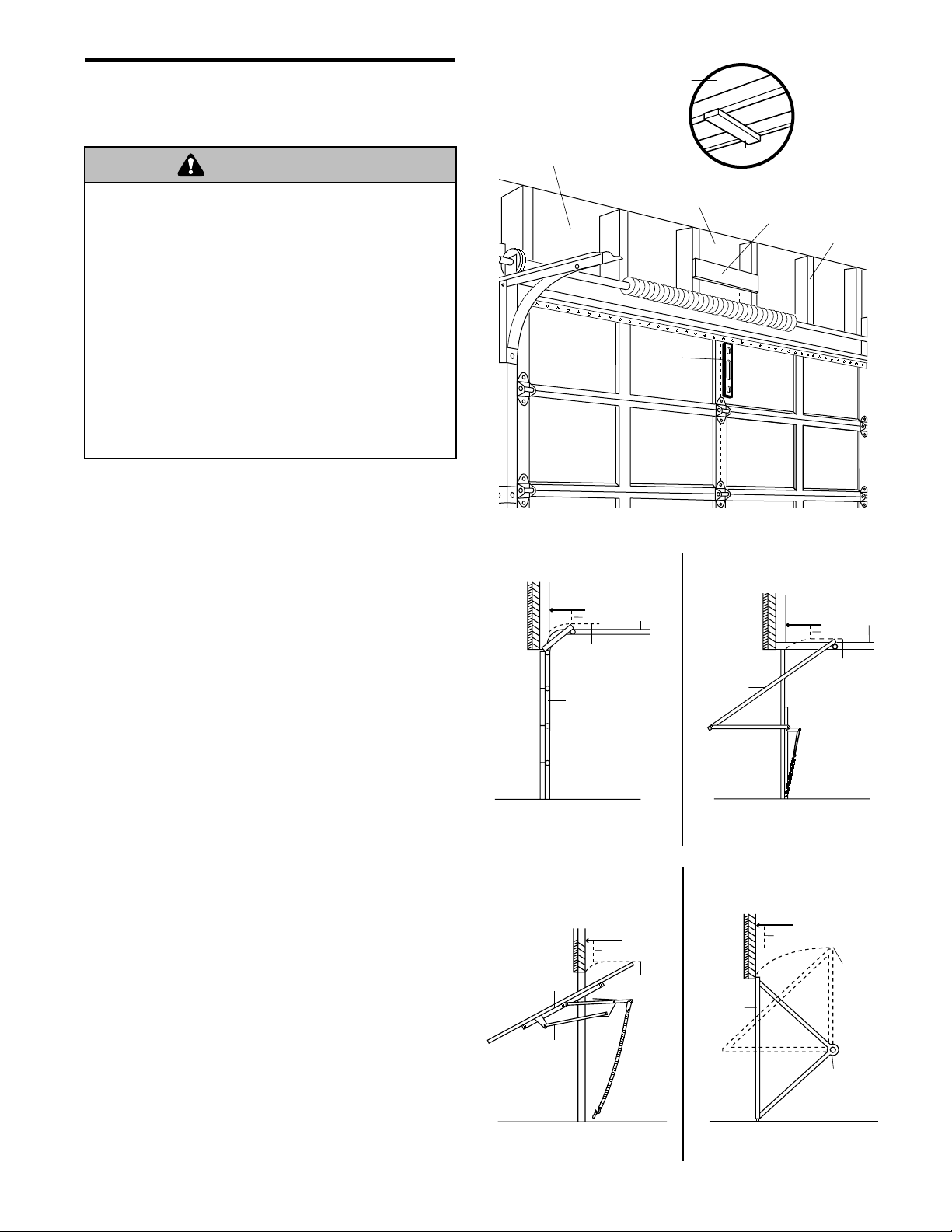
INSTALLATION STEP 1
Determine the Header Bracket
Location
Installation procedures vary according to garage door
types. Follow the instructions which apply to your
door.
1. Close the door and mark the inside vertical
centerline of the garage door.
2. Extend the line onto the header wall above the
door.
You can fasten the header bracket within 4 feet
(1.22 m) of the left or right of the door center
only if a torsion spring or center bearing plate
is in the way; or you can attach it to the ceiling
(see page 13) when clearance is minimal. (It
may be mounted on the wall upside down if
necessary, to gain approximately 1/2" (1 cm).
If you need to install the header bracket on a 2x4
(on wall or ceiling), use lag screws (not provided)
to securely fasten the 2x4 to structural supports as
shown here and on page 13.
3. Open your door to the highest point of travel as
shown. Draw an intersecting horizontal line on the
header wall above the high point:
• 2" (5 cm) above the high point for sectional door
and one-piece door with track.
• 8" (20 cm) above the high point for one-piece
door without track.
This height will provide travel clearance for the top
edge of the door.
NOTE: If the total number of inches exceeds the
height available in your garage, use the maximum
height possible, or refer to page 13 for ceiling
installation.
To prevent possible SERIOUS INJURY or DEATH:
• Header bracket MUST be RIGIDLY fastened to
structural support on header wall or ceiling, otherwise
garage door might not reverse when required. DO NOT
install header bracket over drywall.
• Concrete anchors MUST be used if mounting header
bracket or 2x4 into masonry.
• NEVER try to loosen, move or adjust garage door,
springs, cables, pulleys, brackets, or their hardware,
all of which are under EXTREME tension.
• ALWAYS call a trained door systems technician if
garage door binds, sticks, or is out of balance. An
unbalanced garage door might not reverse when
required.
WARNING
WARNING
Header Wall
Vertical Centerline
of Garage Door
Level
(optional)
Header Wall
2" (5 cm)
Track
Highest Point
of Travel
Door
Sectional door with curved track
Header Wall
8" (20 cm)
Door
Jamb
Hardware
Highest
Point
of Travel
Unfinished
Ceiling
OPTIONAL
CEILING
MOUNT
FOR
HEADER
2x4
Door
One-piece door with horizontal track
Door
BRACKET
2x4
Header Wall
Header Wall
8" (20 cm)
Structural
Supports
Track
2" (5 cm)
Highest Point
of Travel
Highest
Point
of Travel
Pivot
One-piece door without track:
jamb hardware
One-piece door without track:
pivot hardware
Page 13
13
INSTALLATION STEP 2
Install the Header Bracket
You can attach the header bracket either to the wall
above the garage door, or to the ceiling. Follow the
instructions which will work best for your particular
requirements. Do not install the header bracket
over drywall. If installing into masonry, use
concrete anchors (not provided).
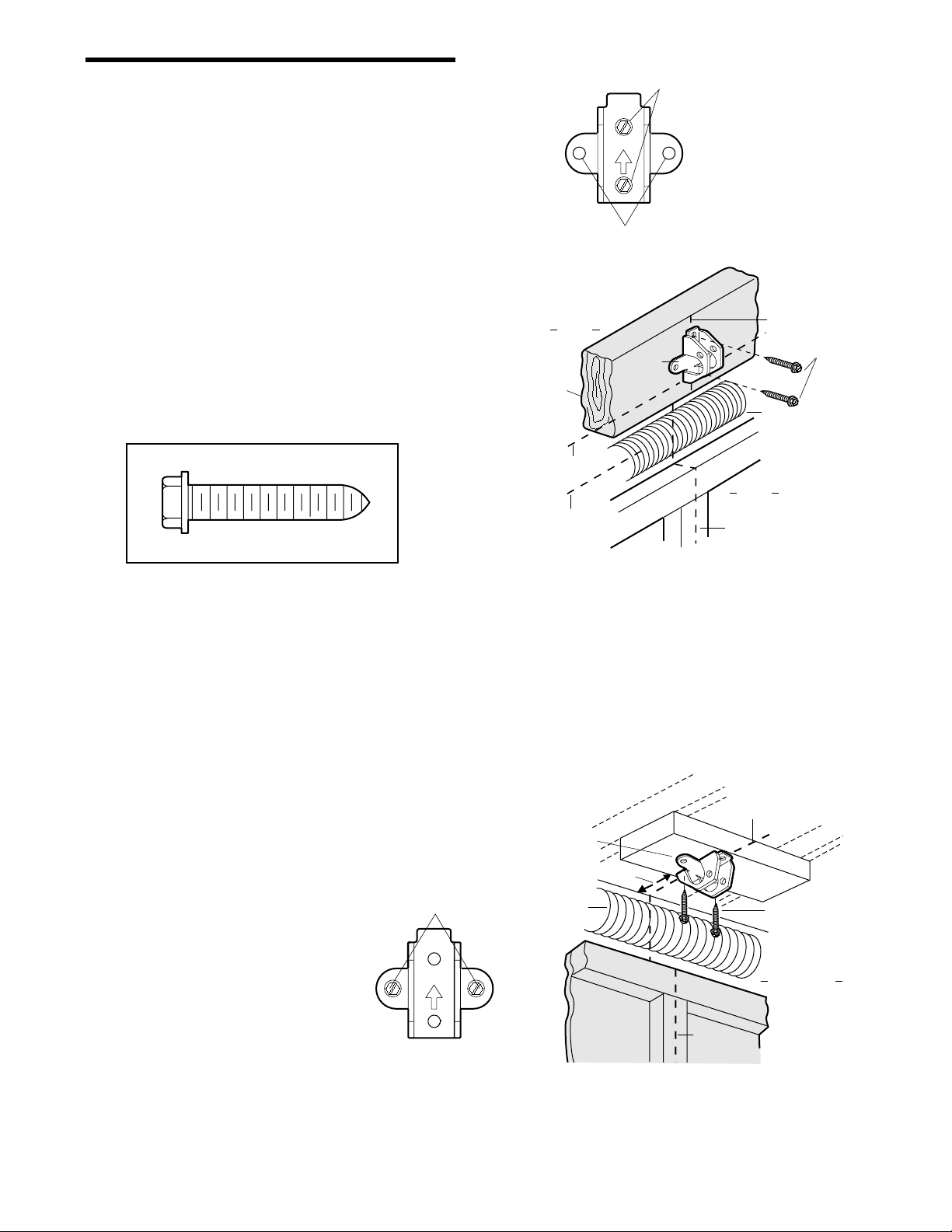
WALL HEADER BRACKET INSTALLATION
• Center the bracket on the vertical centerline with
the bottom edge of the bracket on the horizontal
line as shown (with the arrow pointing toward the
ceiling).
• Mark the vertical set of bracket holes (do not use
the holes designated for ceiling mount). Drill 3/16"
pilot holes and fasten the bracket securely to a
structural support with the hardware provided.
HARDWARE SHOWN ACTUAL SIZE
CEILING HEADER BRACKET INSTALLATION
• Extend the vertical centerline onto the ceiling as
shown.
• Center the bracket on the vertical mark, no more
than 6" (15 cm) from the wall. Make sure the arrow
is pointing away from the wall. The bracket can be
mounted flush against the ceiling when clearance
is minimal.
• Mark the side holes. Drill 3/16" pilot holes and
fasten bracket securely to a structural support with
the hardware provided.
Wall Mount
Lag Screw
5/16"-9x1-5/8"
Optional
Mounting Holes
Header
Wall
2x4
Structural
Support
Horizontal
Line
Highest Point of
Garage Door Travel
UP
Header
Bracket
Vertical
Centerline
of Garage Door
Lag Screws
5/16"x9x1-5/8"
Door Spring
Garage
Door
Vertical
Centerline
of Garage Door
Ceiling Mounting Holes
UP
Header
Bracket
6" (15 cm) Maximum
Door
Spring
Garage Door
— Finished Ceiling —
Vertical Centerline
of Garage Door
Vertical
Centerline
of Garage Door
Lag Screws
5/16"x9x1-5/8"
Header Wall
Page 14
14
INSTALLATION STEP 3
Attach the Rail to the Header
Bracket
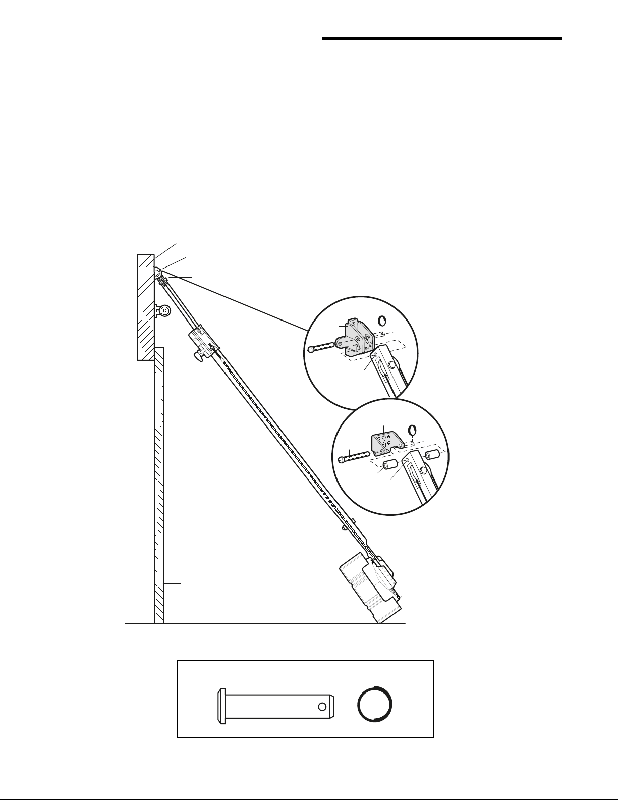
NOTE: (Optional) With some existing installations,
you may re-use the old header bracket with the two
plastic spacers included in the hardware bag. Place
the spacers inside the bracket on each side of the
rail, as illustrated.
• Position the opener on the garage floor below the
header bracket. Use packing material as a
protective base. NOTE: If the door spring is in the
way you’ll need help. Have someone hold the
opener securely on a temporary support to allow
the rail to clear the spring.
• Position the rail bracket against the header
bracket.
• Align the bracket holes and join with a clevis pin
5/16"x1-1/2" as shown.
• Insert a ring fastener to secure.
Opener Carton or
Temporary
Support
Garage
Door
OPTION WITH
SOME EXISTING
INSTALLATIONS
Header Bracket
Idler Pulley
Header Wall
Header
Bracket
Mounting
Hole
Existing
Header Bracket
Spacer
Mounting
Hole
Existing
Clevis Pin
Clevis Pin 5/16"x1-1/2"
Ring Fastener
HARDWARE SHOWN ACTUAL SIZE
Page 15
15
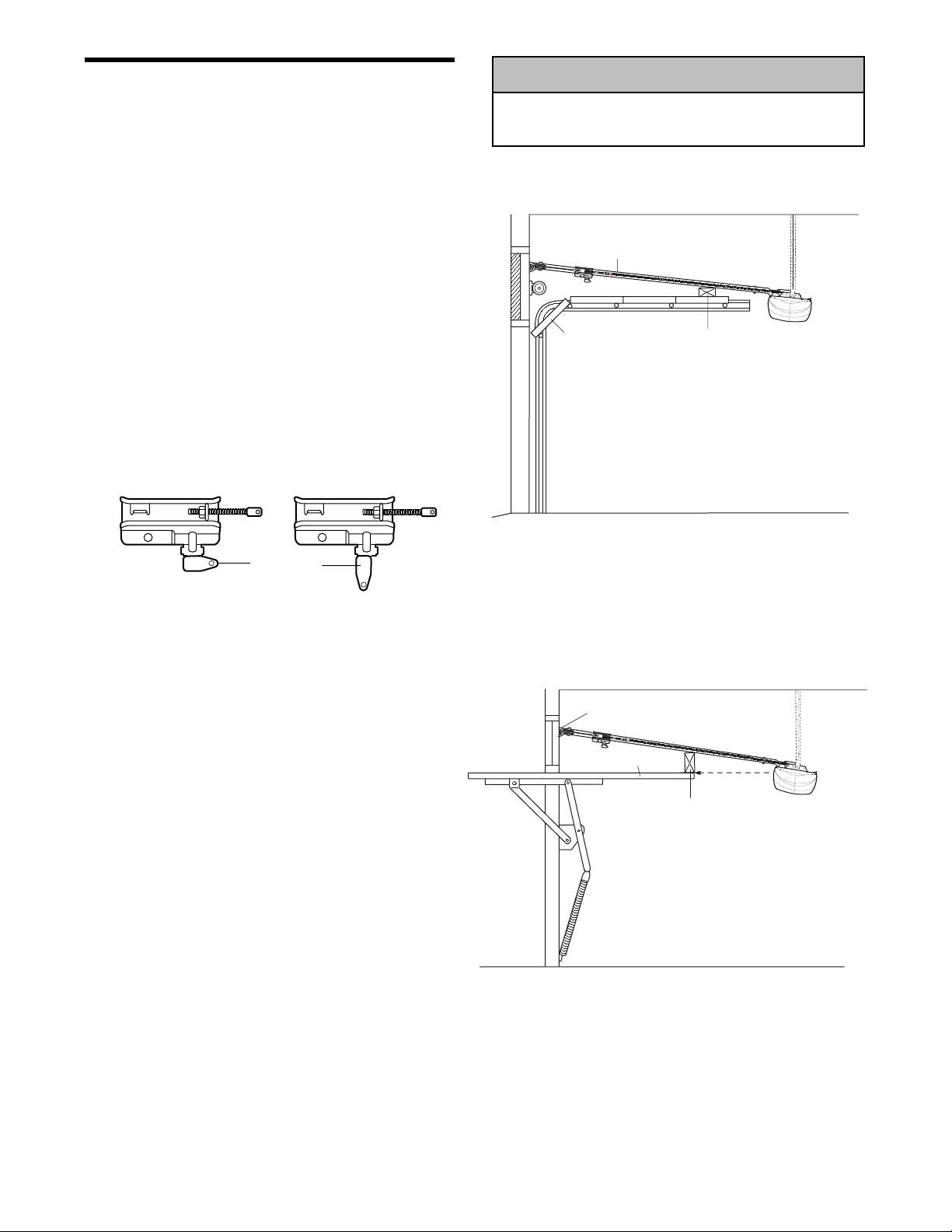
ONE-PIECE DOOR WITHOUT TRACK
A 2x4 on its side is convenient for setting an ideal
door-to-rail distance.
• Remove foam packaging.
• Raise the opener onto a stepladder. You will need
help at this point if the ladder is not tall enough.
• Open the door all the way and place a 2x4 on its
side on the top section of the door beneath the rail.
• The top of the door should be level with the top of
the motor unit. Do not position the opener more
than 4" (10 cm) above this point.
INSTALLATION STEP 4
Position the Opener
Follow instructions which apply to your door type as
illustrated.
SECTIONAL DOOR OR ONE-PIECE DOOR WITH
TRACK
A 2x4 laid flat is convenient for setting an ideal
door-to-rail distance.
• Remove foam packaging.
• Raise the opener onto a stepladder. You will need
help at this point if the ladder is not tall enough.
• Open the door all the way and place a 2x4 laid flat
on the top section beneath the rail.
• If the top section or panel hits the trolley when you
raise the door, pull down on the trolley release arm
to disconnect inner and outer sections. Slide the
outer trolley toward the motor unit. The trolley can
remain disconnected until Installation Step 12
is completed.
To prevent damage to garage door, rest garage door
opener rail on 2x4 placed on top section of door.
WARNING
WARNING
WARNING
CAUTION
Rail
Door
2x4 is used to determine
the correct mounting height
from ceiling.
Trolley
Release Arm
ENGAGED
RELEASED
Header
Bracket
Top of Door
2x4 is used to determine
the correct mounting height
from ceiling.
Page 16
16
INSTALLATION STEP 5
Hang the Opener
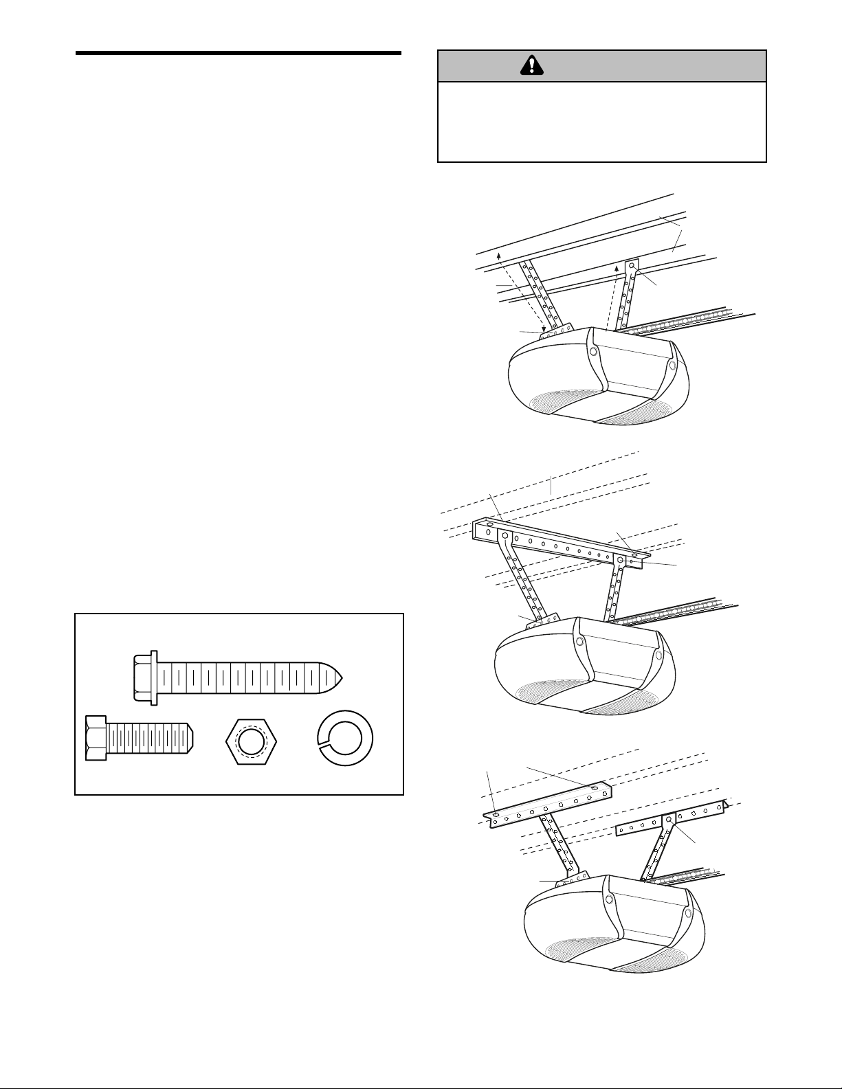
Three representative installations are shown. Yours
may be different. Hanging brackets should be angled
(Figure 1) to provide rigid support. On finished
ceilings (Figure 2 and Figure 3), attach a sturdy
metal bracket to structural supports before installing
the opener. This bracket and fastening hardware are
not provided.
1. Measure the distance from each side of the motor
unit to the structural support.
2. Cut both pieces of the hanging bracket to required
lengths.
3. Drill 3/16" pilot holes in the structural supports.
4. Attach one end of each bracket to a support with
5/16"-18x1-7/8" lag screws.
5. Fasten the opener to the hanging brackets with
5/16"-18x7/8" hex bolts, lock washers and nuts.
6. Check to make sure the rail is centered over the
door (or in line with the header bracket if the
bracket is not centered above the door).
7. Remove the 2x4. Operate the door manually. If the
door hits the rail, raise the header bracket.
NOTE: DO NOT connect power to opener at
this time.
To avoid possible SERIOUS INJURY from a falling
garage door opener, fasten it SECURELY to structural
supports of the garage. Concrete anchors MUST be used
if installing any brackets into masonry.
HARDWARE SHOWN ACTUAL SIZE
Figure 1
Figure 2
WARNING
Figure 3
WARNING
Measure
Distance
Bolt 5/16"-18x7/8"
Lock Washer 5/16"
Nut 5/16"-18
Bracket
(Not Provided)
Lag Screws
5/16"-18x1-7/8"
Hidden
Support
Lag Screws
5/16"-18x1-7/8"
Structural
Supports
FINISHED CEILING
Lag Screw 5/16"-18x1-7/8"
Hex Bolt
5/16"-18x7/8"
Nut 5/16"-18
Lock Washer 5/16"
Bolt 5/16"-18x7/8"
Lock Washer 5/16"
Nut 5/16"-18
Lag Screws
5/16"-18x1-7/8"
Bolt 5/16"-18x7/8"
Lock Washer 5/16"
Nut 5/16"-18
(Not Provided)
Bolt 5/16"-18x7/8"
Lock Washer 5/16"
Nut 5/16"-18
FINISHED CEILING
(Not Provided)
Bolt 5/16"-18x7/8"
Lock Washer 5/16"
Nut 5/16"-18
Page 17
17
To prevent possible SERIOUS INJURY or DEATH from
electrocution:
• Be sure power is not connected BEFORE installing door
control.
• Connect ONLY to 24 VOLT low voltage wires.
To prevent possible SERIOUS INJURY or DEATH from a
closing garage door:
• Install door control within sight of garage door, out of
reach of children at a minimum height of 5 feet
(1.5 m), and away from all moving parts of door.
• NEVER permit children to operate or play with door
control push buttons or remote control transmitters.
• Activate door ONLY when it can be seen clearly, is
properly adjusted, and there are no obstructions to door
travel.
• ALWAYS keep garage door in sight until completely
closed. NEVER permit anyone to cross path of closing
garage door.
WARNING
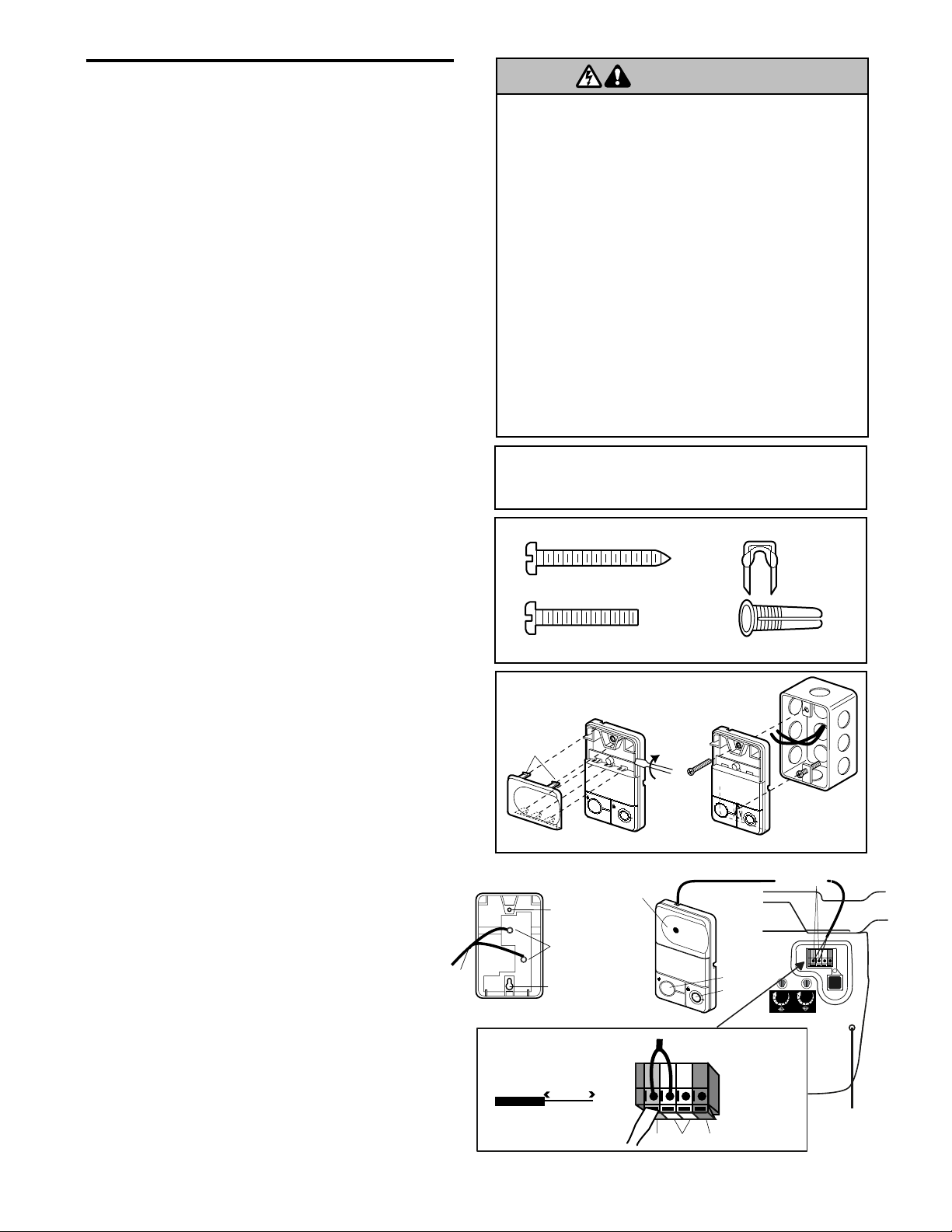
INSTALLATION STEP 6
Install the Door Control
Locate door control within sight of door, at a
minimum height of 5 feet (1.5 m) where small
children cannot reach, away from moving parts of
door and door hardware. If installing into drywall, drill
5/32" holes and use the anchors provided. For
pre-wired installations (as in new home
construction), it may be mounted to a single gang
box (Figure 2).
1. Strip 7/16" (11 mm) of insulation from one end of
bell wire and connect to the two screw terminals
on back of door control by color: white wire to
2 and white/red wire to the 1.
2. Remove cover by gently prying at slot in top of the
cover with a small flat head screwdriver. Fasten
with 6ABx1-1/4" self-tapping screws (drywall
installation) or 6-32x1" machine screws (into gang
box) as follows:
• Install bottom screw, allowing 1/8" (3 mm) to
protrude above wall surface.
• Position bottom of door control on screw head
and slide down to secure. Adjust screw
for snug fit.
• Drill and install top screw with care to avoid
cracking plastic housing. Do not overtighten.
• Insert top tabs and snap on cover.
3. (For standard installation only) Run bell wire up
wall and across ceiling to motor unit. Use
insulated staples to secure wire in several places.
Do not pierce wire with a staple, creating a short
or open circuit.
4. Strip 7/16" (11 mm) of insulation from end of bell
wire. Connect bell wire to the quick-connect
terminals as follows: white to white and white/red
to red.
NOTE: When connecting multiple door controls to
the opener, twist same color wires together. Insert
wires into quick-connect holes: white to white and
red/white to red.
5. Position the antenna wire as shown.
6. Use tacks or staples to permanently attach
entrapment warning label to wall near door
control, and manual release/safety reverse test
label in a prominent location on inside of
garage door.
NOTE: DO NOT connect power and operate
opener at this time. The trolley will travel to the full
open position but will not return to the close
position until the sensor beam is connected and
properly aligned.
HARDWARE SHOWN ACTUAL SIZE
Outside Keylock Accessory Connections
To opener quick-connect terminals: white to white;
white/red to red.
PREMIUM
CONTROL CONSOLE
Terminal
Screws
(BACK VIEW)
Top
Mounting
Hole
Bottom
Mounting
Hole
WHITE
2
RED
1
Bell
Wire
Strip wire 7/16" (11 mm)
7/16" (11 mm)
Red GreyWhite
Lock
Light
Lighted
Push Button
L
O
C
K
L
IG
H
T
2-Conductor
Bell Wire
Quick-Connect
Terminals
Antenna
To release wire, push in
tab with screwdriver tip
Door Control
Connections
WARNING
Screw 6ABx1-1/4"
Control Panel (std installation)
Screw 6-32x1"
Control Panel (pre-wired)
Figure 1 Figure 2
Twist
Here
PRE-WIRED
INSTALLATION
REMOVE & REPLACE COVER
L
I
G
H
T
To Remove,
L
O
C
K
To Replace,
Insert Top
Tabs First
Insulated
Staples
Drywall Anchors
24 Volt
2-Conductor
Bell Wire
Page 18
18
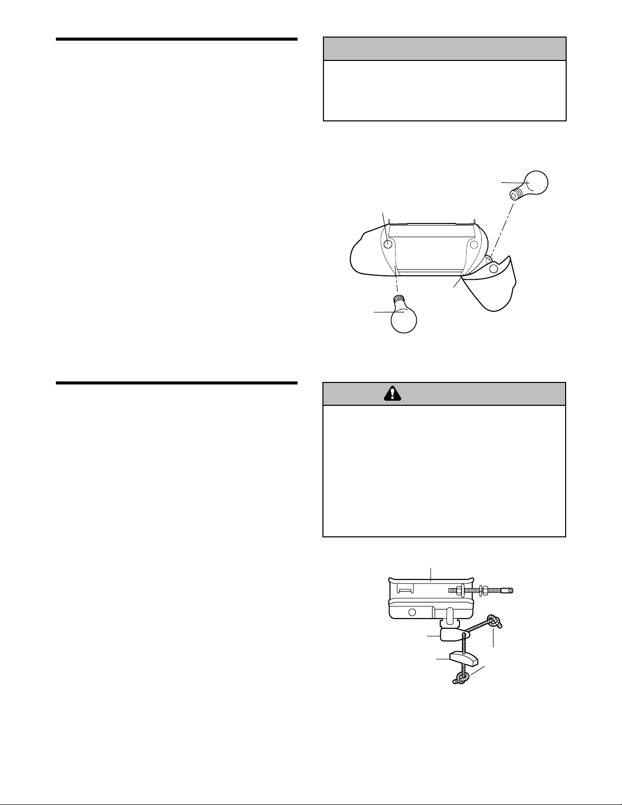
INSTALLATION STEP 7
Install the Lights
• Press the release tabs on both sides of lens.
Gently rotate lens back and downward until the
lens hinge is in the fully open position. Do not
remove the lens.
• Install up to a 100 watt maximum light bulb in each
socket. The lights will turn ON and remain lit for
approximately 4-1/2 minutes when power is
connected. Then the lights will turn OFF.
• Reverse the procedure to close the lens.
• If the bulbs burn out prematurely due to vibration,
replace with a Garage Door Opener bulb.
NOTE: Use only standard light bulbs. The use of
short neck or speciality light bulbs may overheat the
endpanel or light socket.
INSTALLATION STEP 8
Attach the Emergency Release
Rope and Handle
• Thread one end of the rope through the hole in the
top of the red handle so “NOTICE” reads right side
up as shown. Secure with an overhand knot at
least 1" (2.5 cm) from the end of the rope to
prevent slipping.
• Thread the other end of the rope through the hole
in the release arm of the outer trolley.
• Adjust rope length so the handle is 6 feet (1.83 m)
above the floor. Ensure that the rope and handle
clear the tops of all vehicles to avoid
entanglement. Secure with an overhand knot.
NOTE: If it is necessary to cut the rope, heat seal
the cut end with a match or lighter to prevent
unraveling.
To prevent possible SERIOUS INJURY or DEATH from a
falling garage door:
• If possible, use emergency release handle to disengage
trolley ONLY when garage door is CLOSED. Weak or
broken springs or unbalanced door could result in an
open door falling rapidly and/or unexpectedly.
• NEVER use emergency release handle unless garage
doorway is clear of persons and obstructions.
• NEVER use handle to pull door open or closed. If rope
knot becomes untied, you could fall.
WARNING
To prevent possible OVERHEATING of the endpanel or
light socket:
• DO NOT use short neck or specialty light bulbs.
• DO NOT use halogen bulbs. Use ONLY incandescent.
WARNING
WARNING
WARNING
CAUTION
100 Watt (Max)
Standard Light Bulb
Release Tab
100 Watt (Max)
Standard
Light Bulb
Lens
Hinge
WARNING
Trolley
Trolley
Release arm
Emergency
Release Handle
NOTICE
Overhand
Knot
Page 19
19
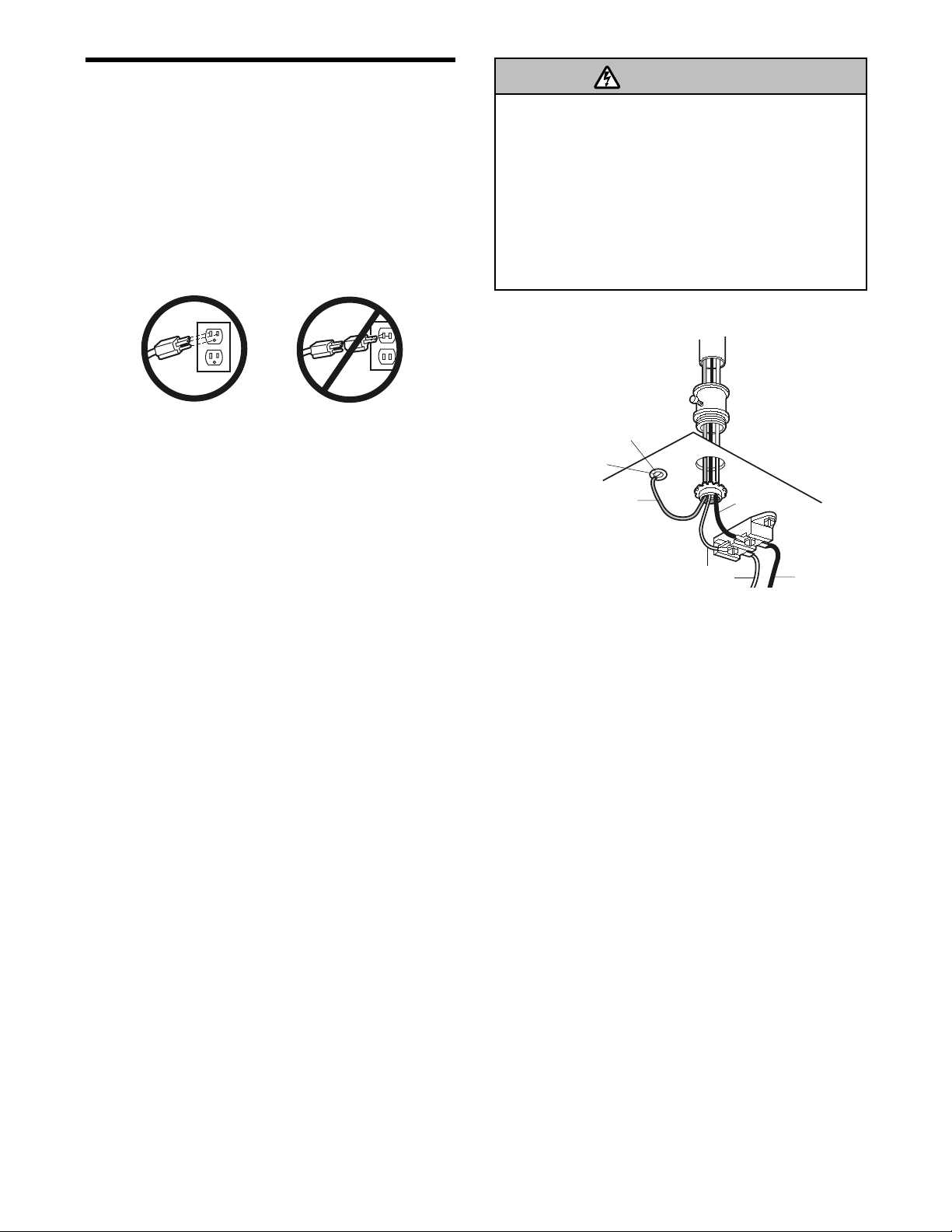
INSTALLATION STEP 9
Electrical Requirements
To avoid installation difficulties, do not run the
opener at this time.
To reduce the risk of electric shock, your garage door
opener has a grounding type plug with a third
grounding pin. This plug will only fit into a grounding
type outlet. If the plug doesn't fit into the outlet you
have, contact a qualified electrician to install the
proper outlet.
If permanent wiring is required by your local
code, refer to the following procedure.
To make a permanent connection through the 7/8"
hole in the top of the motor unit:
• Remove the motor unit cover screws and set the
cover aside.
• Remove the attached 3-prong cord.
• Connect the black (line) wire to the screw on the
brass terminal; the white (neutral) wire to the
screw on the silver terminal; and the ground wire
to the green ground screw. The opener must be
grounded.
• Reinstall the cover.
To avoid installation difficulties, do not run the
opener at this time.
To prevent possible SERIOUS INJURY or DEATH from
electrocution or fire:
• Be sure power is not connected to the opener, and
disconnect power to circuit BEFORE removing cover to
establish permanent wiring connection.
• Garage door installation and wiring MUST be in
compliance with all local electrical and building codes.
• NEVER use an extension cord, 2-wire adapter, or
change plug in any way to make it fit outlet. Be sure
the opener is grounded.
RIGHT
WRONG
WARNING
PERMANENT WIRING
CONNECTION
Green
Ground Screw
Ground Wire
Ground Tab
White Wire
Black
Wire
Black Wire
Page 20

20
Facing the door from inside the garage
INSTALLATION STEP 10
Install The Protector System
®
The safety reversing sensor must be connected
and aligned correctly before the garage door
opener will move in the down direction.
IMPORTANT INFORMATION ABOUT
THE SAFETY REVERSING SENSOR
When properly connected and aligned, the sensor
will detect an obstacle in the path of its electronic
beam. The sending eye (with an amber indicator
light) transmits an invisible light beam to the
receiving eye (with a green indicator light). If an
obstruction breaks the light beam while the door is
closing, the door will stop and reverse to full open
position, and the opener lights will flash 10 times.
The units must be installed inside the garage so that
the sending and receiving eyes face each other
across the door, no more than 6" (15 cm) above the
floor. Either can be installed on the left or right of the
door as long as the sun never shines directly into the
receiving eye lens.
The mounting brackets are designed to clip onto the
track of sectional garage doors without additional
hardware.
If it is necessary to mount the units on the wall, the
brackets must be securely fastened to a solid
surface such as the wall framing. Extension brackets
(see accessories) are available if needed. If
installing in masonry construction, add a piece of
wood at each location to avoid drilling extra holes in
masonry if repositioning is necessary.
The invisible light beam path must be unobstructed.
No part of the garage door (or door tracks, springs,
hinges, rollers or other hardware) may interrupt the
beam while the door is closing.
Be sure power is not connected to the garage door
opener BEFORE installing the safety reversing sensor.
To prevent SERIOUS INJURY or DEATH from a closing
garage door:
• Correctly connect and align the safety reversing
sensor. This required safety device MUST NOT be
disabled.
• Install the safety reversing sensor so beam is NO
HIGHER than 6" (15 cm) above garage floor.
WARNING
WARNING
Sensor Beam
6" (15 cm) max.
above floor
Invisible Light Beam
Protection Area
Sensor Beam
6" (15 cm) max.
above floor
Page 21
21
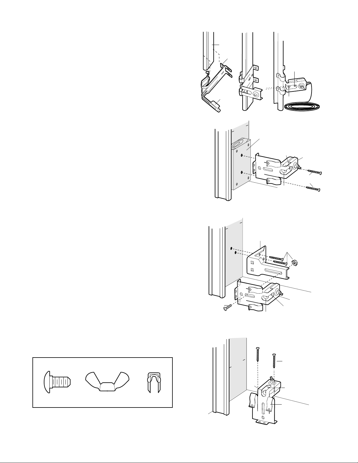
INSTALLING THE BRACKETS
Be sure power to the opener is disconnected.
Install and align the brackets so the sensors will face
each other across the garage door, with the beam no
higher than 6" (15 cm) above the floor. They may be
installed in one of three ways, as follows.
Garage door track installation (preferred):
• Slip the curved arms over the rounded edge of
each door track, with the curved arms facing the
door. Snap into place against the side of the track.
It should lie flush, with the lip hugging the back
edge of the track, as shown in Figure 1.
If your door track will not support the bracket
securely, wall installation is recommended.
Wall installation (Figure 2 & 3):
• Place the bracket against the wall with curved
arms facing the door. Be sure there is enough
clearance for the sensor beam to be unobstructed.
• If additional depth is needed, an extension bracket
(See Accessories) or wood blocks can be used.
• Use bracket mounting holes as a template to
locate and drill (2) 3/16" diameter pilot holes on
the wall at each side of the door, no higher than 6"
(15 cm) above the floor.
• Attach brackets to wall with lag screws
(Not provided).
• If using extension brackets or wood blocks, adjust
right and left assemblies to the same distance out
from the mounting surface. Make sure all door
hardware obstructions are cleared.
Floor installation (Figure 4):
• Use wood blocks or extension brackets (See
Accessories) to elevate sensor brackets so the
lenses will be no higher than 6" (15 cm) above the
floor.
• Carefully measure and place right and left
assemblies at the same distance out from the wall.
Be sure all door hardware obstructions are
cleared.
• Fasten to the floor with concrete anchors as
shown.
HARDWARE SHOWN ACTUAL SIZE
Figure 1
Figure 2
Figure 3
(Provided with
Extension
Bracket)
DOOR TRACK MOUNT (RIGHT SIDE)
Door
Track
Lip
Sensor
Bracket
WALL MOUNT (RIGHT SIDE)
Fasten Wood Block to Wall with
Lag Screws (Not Provided)
WALL MOUNT (RIGHT SIDE)
Extension
Bracket
(See Accessories)
Lens
Inside
arage
G
all
W
Inside
arage
G
all
W
Indicator
Light
Lens
Indicator
Light
Lens
(Provided with
Extension Bracket)
Indicator
Light
Sensor
Bracket
Lag Screws
(Not Provided)
Sensor
Bracket
Carriage Bolt
1/4"-20x1/2"
Wing Nut
1/4"-20
Staples
Figure 4
Inside
arage
G
all
W
FLOOR MOUNT (RIGHT SIDE)
Attach with
Concrete Anchors
(Not Provided)
Lens
Indicator
Light
Sensor
Bracket
Page 22
22
Figure 5MOUNTING AND WIRING THE SAFETY SENSORS
• Slide a 1/4"-20x1/2" carriage bolt head into the slot
on each sensor. Use wing nuts to fasten sensors to
brackets, with lenses pointing toward each other
across the door. Be sure the lens is not obstructed
by a bracket extension (Figure 5).
• Finger tighten the wing nuts.
• Run the wires from both sensors to the opener. Use
insulated staples to secure wire to wall and ceiling.
• Strip 7/16" (11 mm) of insulation from each set of
wires. Separate white and white/black wires
sufficiently to connect to the opener quick-connect
terminals. Twist like colored wires together. Insert
wires into quick-connect holes: white to white and
white/black to grey (Figure 6).
ALIGNING THE SAFETY SENSORS
• Plug in the opener. The indicator lights in both the
sending and receiving eyes will glow steadily if
wiring connections and alignment are correct.
The sending eye amber indicator light will glow
regardless of alignment or obstruction. If the green
indicator light in the receiving eye is off, dim, or
flickering (and the invisible light beam path is not
obstructed), alignment is required.
• Loosen the sending eye wing nut and readjust,
aiming directly at the receiving eye. Lock in place.
• Loosen the receiving eye wing nut and adjust
sensor until it receives the sender’s beam. When
the green indicator light glows steadily, tighten the
wing nut.
TROUBLESHOOTING THE SAFETY SENSORS
1. If the sending eye indicator light does not glow
steadily after installation, check for:
• Electric power to the opener.
• A short in the white or white/black wires. These
can occur at staples, or at opener connections.
• Incorrect wiring between sensors and opener.
• A broken wire.
2. If the sending eye indicator light glows steadily but
the receiving eye indicator light doesn't:
• Check alignment.
• Check for an open wire to the receiving eye.
3. If the receiving eye indicator light is dim, realign
either sensor.
NOTE: When the invisible beam path is obstructed
or misaligned while the door is closing, the door will
reverse. If the door is already open, it will not close.
The opener lights will blink 10 times. See page 20.
Invisible Light Beam
Protection Area
Sensor
Sensor
Connect Wire to
Quick-Connect Terminals
Bell Wire
Bell Wire
Finished
Ceiling
Quick-Connect Terminals
3. Insert into
appropriate terminals
1. Strip wire 7/16"
(11 mm)
2. Twist like colored
wires together
7/16" (11 mm)
Red
Grey
White
Figure 6
Wing Nut
Carriage Bolt
1/4"-20x1/2"
Lens
Page 23
23
Fiberglass, aluminum or lightweight steel garage doors
WILL REQUIRE reinforcement BEFORE installation of
door bracket. Contact your door manufacturer for
reinforcement kit.
WARNING
WARNING
WARNING
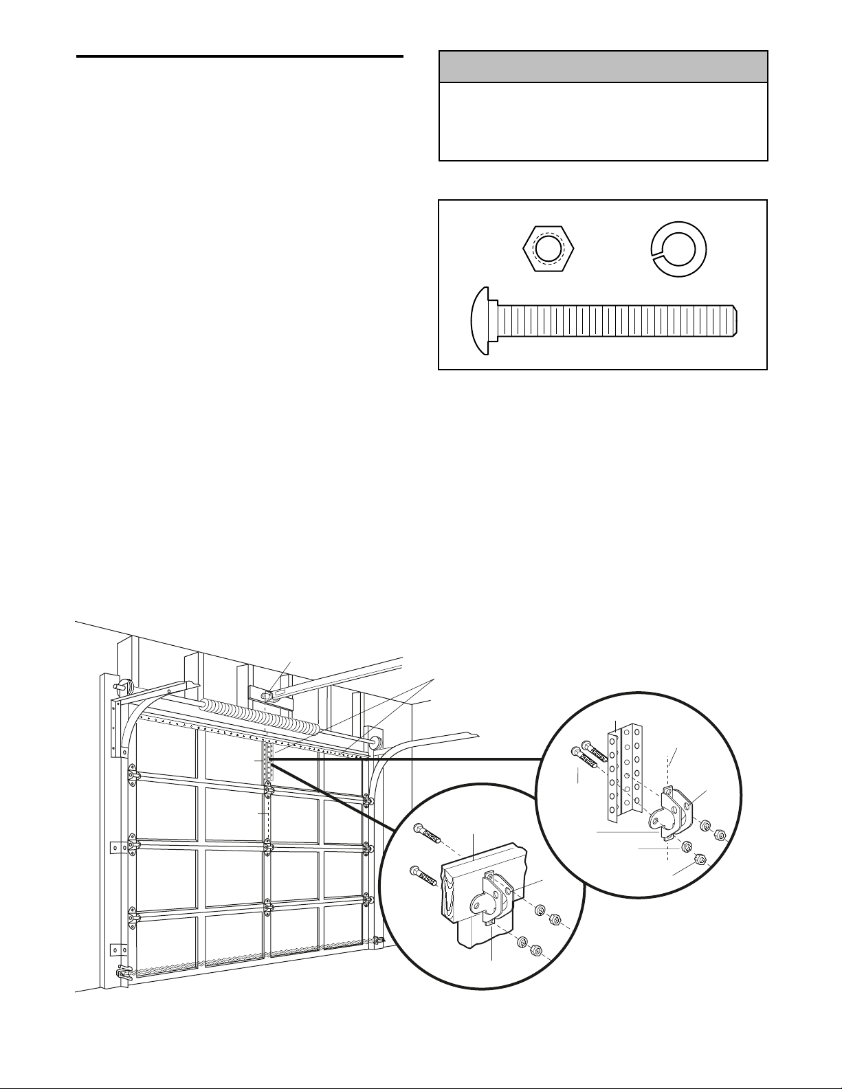
INSTALLATION STEP 11
Fasten the Door Bracket
Follow instructions which apply to your door type
as illustrated below or on the following page.
A horizontal reinforcement brace should be long
enough to be secured to two vertical supports. A
vertical reinforcement brace should cover the
height of the top panel.
The illustration shows one piece of angle iron as the
horizontal brace. For the vertical brace, two pieces of
angle iron are used to create a U-shaped support
(Figure 1). The best solution is to check with your
garage door manufacturer for an opener installation
door reinforcement kit.
NOTE: Many vertical brace installations provide for
direct attachment of the clevis pin and door arm. In
this case you will not need the door bracket; proceed
to Installation Step 12.
SECTIONAL DOORS
• Center the door bracket on the previously marked
vertical centerline used for the header bracket
installation. Note correct UP placement, as
stamped inside the bracket (Figure 2).
• Position the bracket on the face of the door within
the following limits:
A) The top edge of the bracket 2"-4" (5-10 cm)
below the top edge of the door.
B) The top edge of the bracket directly below any
structural support across the top of the door.
Vertical
Centerline
of Garage
Door
Door
Bracket
Location
Header Bracket
Horizontal and vertical reinforcement
is needed for lightweight garage doors
(fiberglass, aluminum, steel, doors with
glass panel, etc.). (Not Provided)
UP
Door Bracket
Inside Edge
of Door or
Reinforcement Board
Door
Bracket
Nut
5/16"-18
Carriage Bolt
5/16"-18x2-1/2"
Lock Washer
5/16"
Vertical
Centerline
of Garage
Door
UP
Vertical
Reinforcement
HARDWARE SHOWN ACTUAL SIZE
Figure 1
Figure 2
• Mark and drill 5/16" left and right fastening holes.
Secure the bracket as shown in Figure 1 if there is
vertical reinforcement.
If your installation doesn't require vertical
reinforcement but does need top and bottom
fastening holes for the door bracket, fasten as shown
in Figure 2.
CAUTION
Nut 5/16"-18
Carriage Bolt
5/16"-18x2-1/2"
Lock Washer 5/16"
Page 24
24
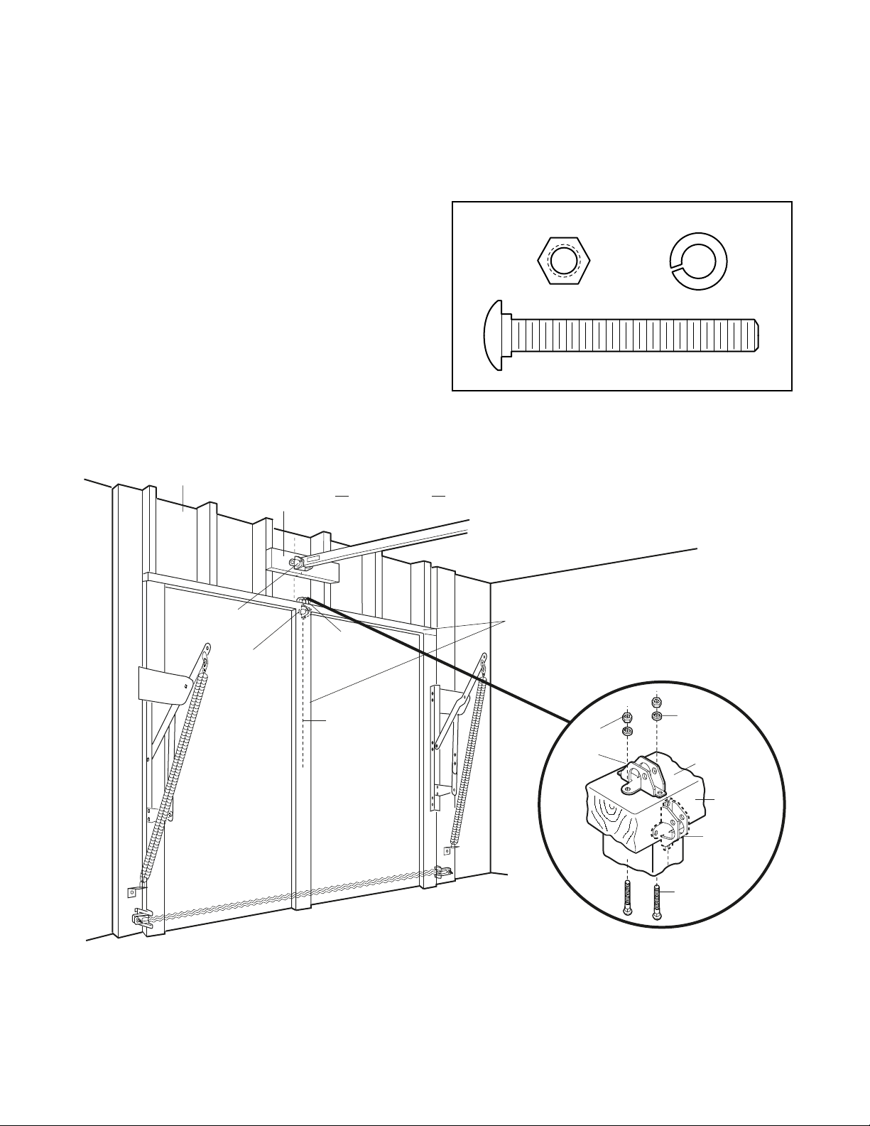
ONE-PIECE DOORS
Please read and comply with the warnings and
reinforcement instructions on the previous page.
They apply to one-piece doors also.
• Center the door bracket on the top of the door, in
line with the header bracket as shown. Mark either
the left and right, or the top and bottom holes.
• Drill 5/16" pilot holes and fasten the bracket with
hardware supplied.
If the door has no exposed framing, drill 3/16" pilot
holes and fasten the bracket with 5/16"x1-1/2" lag
screws (not provided) to the top of the door.
NOTE: The door bracket may be installed on the top
edge of the door if required for your installation.
(Refer to the dotted line optional placement drawing.)
Drill 3/16" pilot holes and substitute 5/16"x1-1/2" lag
screws (not provided) to fasten the bracket to the
door.
HARDWARE SHOWN ACTUAL SIZE
Nut 5/16"-18
Carriage Bolt
5/16"-18x2-1/2"
Lock Washer 5/16"
Header Wall
Header
Bracket
Optional
Placement
of Door
Bracket
2x4
Finished Ceiling
Door
Bracket
Vertical
Centerline
of Garage
Door
Horizontal and vertical
reinforcement is needed for
lightweight garage doors
(fiberglass, aluminum, steel,
door with glass panel, etc.).
(Not Provided)
For a door with no exposed framing,
or for the optional installation, use
5/16"x1-1/2" lag screws (Not Provided)
to fasten door bracket.
Nut
5/16"-18
Door
Bracket
Lock
Washer
5/16"
Top of Door
(Inside Garage)
Top Edge
of Door
Optional
Placement
Carriage Bolt
5/16"-18x2-1/2"
Page 25

25
INSTALLATION STEP 12
Connect Door Arm to Trolley
Follow instructions which apply to your door type as
illustrated below and on the following page.
SECTIONAL DOORS ONLY
• Make sure garage door is fully closed. Pull the
emergency release handle to disconnect the outer
trolley from the inner trolley. Slide the outer trolley
back (away from the pulley) about 8" (20 cm) as
shown in Figures 1, 2 and 3.
• Figure 1:
– Fasten straight door arm section to outer trolley
with the 5/16"x1" clevis pin. Secure the
connection with a ring fastener.
– Fasten curved section to the door bracket in the
same way, using the 5/16"x1-1/4" clevis pin.
• Figure 2:
– Bring arm sections together. Find two pairs of
holes that line up and join sections. Select holes
as far apart as possible to increase door arm
rigidity.
• Figure 3, Hole alignment alternative:
– If holes in curved arm are above holes in straight
arm, disconnect straight arm. Cut about 6"
(15 cm) from the solid end. Reconnect to trolley
with cut end down as shown.
– Bring arm sections together.
– Find two pairs of holes that line up and join with
bolts, lock washers and nuts.
• Pull the emergency release handle toward the
opener at a 45° angle so that the trolley release
arm is horizontal. Proceed to Adjustment Step 1,
page 27. Trolley will re-engage automatically when
opener is operated.
Figure 1
Figure 2
Figure 3
HARDWARE SHOWN ACTUAL SIZE
Clevis Pin
5/16"x1-1/4"
Pulley
Trolley
Stop Bolt
Pulley
8" (20 cm) min.
Trolley
Stop Bolt
Nuts
5/16"-18
Door Bracket
8" (20 cm) min.
Inner
Ring
Fastener
Door
Bracket
Lock
Washers
5/16"
Trolley
Curved Door Arm
Outer
Trolley
Emergency
Release
Handle
Straight
Door Arm
Bolts
5/16"-18x7/8"
Clevis Pin
5/16"x1"
Nut 5/16"-18
Clevis Pin
5/16"x1" (Trolley)
Lock Washer 5/16"
Clevis Pin
5/16"x1-1/4" (Door Bracket)
Ring Fastener
Hex Bolt
5/16"-18x7/8"
Pulley
Nuts
5/16"-18
8" (20 cm
Trolley
Stop Bolt
Lock
Washers
5/16"
) m
in.
Cut this end
Bolts
5/16"-18x7/8"
Page 26

26
ALL ONE-PIECE DOORS
1. Assemble the door arm, Figure 4:
• Fasten the straight and curved door arm sections
together to the longest possible length (with a 2
or 3 hole overlap).
• With the door closed, connect the straight door
arm section to the door bracket with the
5/16"x1-1/4" clevis pin.
• Secure with a ring fastener.
2. Adjustment procedures, Figure 5:
• On one-piece doors, before connecting the door
arm to the trolley, the travel limits must be
adjusted. Limit adjustment screws are located on
the left side panel as shown on page 27. Follow
adjustment procedures below.
• Open door adjustment: decrease UP
travel limit
- Turn the UP limit adjustment screw
counter-clockwise 4 turns.
- Press the Door Control push button. The trolley
will travel to the fully open position.
- Manually raise the door to the open position
(parallel to the floor), and lift the door arm to the
trolley. The arm should touch the trolley just in
back of the door arm connector hole. Refer to
the fully open trolley/door arm positions in the
illustration. If the arm does not extend far
enough, adjust the limit further. One full turn
equals 2" (5 cm) of trolley travel.
• Closed door adjustment: decrease DOWN
travel limit
- Turn the DOWN limit adjustment screw
clockwise 4 complete turns.
- Press the Door Control push button. The trolley
will travel to the fully closed position.
- Manually close the door and lift the door arm to
the trolley. The arm should touch the trolley just
ahead of the door arm connector hole. Refer to
the fully closed trolley/door arm positions in the
illustration. If the arm is behind the connector
hole, adjust the limit further. One full turn equals
2" (5 cm) of trolley travel.
3. Connect the door arm to the trolley:
• Close the door and join the curved arm to the
connector hole in the trolley with the remaining
clevis pin. It may be necessary to lift the door
slightly to make the connection.
• Secure with a ring fastener.
• Run the opener through a complete travel cycle.
If the door has a slight “backward” slant in full
open position as shown in the illustration,
decrease the UP limit until the door is parallel
to the floor.
NOTE: When setting the up limit on the following
page, the door should not have a “backward” slant
when fully open as illustrated below. A slight
backward slant will cause unnecessary bucking
and/or jerking operation as the door is being opened
or closed from the fully open position.
Figure 4
Figure 5
Inner Trolley
Outer Trolley
Door
Bracket
Clevis Pin
5/16"x1-1/4"
Straight
Arm
Bolts
5/16"-18x7/8
Ring
Fastener
Lock
Washers
5/16"
Nuts
5/16"-18
Curved
Door Arm
Door Arm
Closed
Door
Inner Trolley
Open Door
Emergency Release Handle
Outer Trolley
Correct Angle
Door with
Backward Slant
(Incorrect)
Page 27

27
ADJUSTMENT STEP 1
Adjust the UP and DOWN Travel
Limits
Limit adjustment settings regulate the points at which
the door will stop when moving up or down.
To operate the opener, press the Door Control push
bar. Run the opener through a complete travel cycle.
• Does the door open and close completely?
• Does the door stay closed and not reverse
unintentionally when fully closed?
If your door passes both of these tests, no limit
adjustments are necessary unless the reversing test
fails (Adjustment Step 3, page 29).
Adjustment procedures are outlined below. Read the
procedures carefully before proceeding to
Adjustment Step 2. Use a screwdriver to make limit
adjustments. Run the opener through a complete
travel cycle after each adjustment.
NOTE: Repeated operation of the opener during
adjustment procedures may cause the motor to
overheat and shut off. Simply wait 15 minutes and
try again.
NOTE: If anything interferes with the door’s upward
travel, it will stop. If anything interferes with the
door’s downward travel (including binding or
unbalanced doors), it will reverse.
HOW AND WHEN TO ADJUST THE LIMITS
• If the door does not open completely but opens
at least five feet (1.5 m):
Increase up travel. Turn the UP limit adjustment
screw clockwise. One turn equals 2" (5 cm) of
travel.
NOTE: To prevent the trolley from hitting the cover
protection bolt, keep a minimum distance of 2-4"
(5 cm - 10 cm) between the trolley and the bolt.
• If door does not open at least 5 feet (1.5 m):
Adjust the UP (open) force as explained in
Adjustment Step 2.
• If the door does not close completely:
Increase down travel. Turn the down limit
adjustment screw counterclockwise. One turn
equals 2" (5 cm) of travel.
If door still won't close completely and the trolley
bumps into the pulley bracket (page 4), try
lengthening the door arm (page 25) and
decreasing the down limit.
• If the opener reverses in fully closed position:
Decrease down travel. Turn the down limit
adjustment screw clockwise. One turn equals 2"
(5 cm) of travel.
Without a properly installed safety reversal system,
persons (particularly small children) could be
SERIOUSLY INJURED or KILLED by a closing garage
door.
• Incorrect adjustment of garage door travel limits will
interfere with proper operation of safety reversal
system.
• If one control (force or travel limits) is adjusted, the
other control may also need adjustment.
• After ANY adjustments are made, the safety reversal
system MUST be tested. Door MUST reverse on
contact with 1-1/2" high (3.8 cm) object (or 2x4 laid
flat) on floor.
• If the door reverses when closing and there is
no visible interference to travel cycle:
If the opener lights are flashing, the Safety
Reversing Sensors are either not installed,
misaligned, or obstructed. See Troubleshooting,
page 22.
Test the door for binding: Pull the emergency
release handle. Manually open and close the door.
If the door is binding or unbalanced, call for a
trained door systems technician. If the door is
balanced and not binding, adjust the DOWN
(close) force. See Adjustment Step 2.
WARNING
To prevent damage to vehicles, be sure fully open door
provides adequate clearance.
WARNING
WARNING
WARNING
WARNING
CAUTION
Cover Protection Bolt
2-4"
(5 cm10 cm)
Left Panel
ADJUSTMENT LABEL
Limit Adjustment
Screws
Page 28

28
ADJUSTMENT STEP 2
Adjust the Force
Force adjustment controls are located on the right
panel of the motor unit. Force adjustment settings
regulate the amount of power required to open and
close the door.
If the forces are set too light, door travel may be
interrupted by nuisance reversals in the down
direction and stops in the up direction. Weather
conditions can affect the door movement, so
occasional adjustment may be needed.
The maximum force adjustment range is about
3/4 of a complete turn. Do not force controls
beyond that point. Turn force adjustment controls
with a screwdriver.
NOTE: If anything interferes with the door’s upward
travel, it will stop. If anything interferes with the
door’s downward travel (including binding or
unbalanced doors), it will reverse.
HOW AND WHEN TO ADJUST THE FORCES
1. Test the DOWN (close) force
• Grasp the door bottom when the door is about
halfway through DOWN (close) travel. The door
should reverse. Reversal halfway through down
travel does not guarantee reversal on a 1-1/2"
(3.8 cm) obstruction. See Adjustment Step 3,
page 29. If the door is hard to hold or doesn't
reverse, DECREASE the DOWN (close) force by
turning the control counterclockwise. Make small
adjustments until the door reverses normally.
After each adjustment, run the opener through a
complete cycle.
• If the door reverses during the down (close)
cycle and the opener lights aren't flashing,
INCREASE DOWN (close) force by turning the
control clockwise. Make small adjustments until
the door completes a close cycle. After each
adjustment, run the opener through a complete
travel cycle. Do not increase the force beyond the
minimum amount required to close the door.
2. Test the UP (open) force
• Grasp the door bottom when the door is about
halfway through UP (open) travel. The door
should stop. If the door is hard to hold or
doesn't stop, DECREASE UP (open) force by
turning the control counterclockwise. Make small
adjustments until the door stops easily and opens
fully. After each adjustment, run the opener
through a complete travel cycle.
• If the door doesn’t open at least 5 feet (1.5 m),
INCREASE UP (open) force by turning the
control clockwise. Make small adjustments until
door opens completely. Readjust the UP limit if
necessary. After each adjustment, run the opener
through a complete travel cycle.
Without a properly installed safety reversal system,
persons (particularly small children) could be
SERIOUSLY INJURED or KILLED by a closing garage
door.
• Too much force on garage door will interfere with
proper operation of safety reversal system.
• NEVER increase force beyond minimum amount
required to close garage door.
• NEVER use force adjustments to compensate for a
binding or sticking garage door.
• If one control (force or travel limits) is adjusted, the
other control may also need adjustment.
• After ANY adjustments are made, the safety reversal
system MUST be tested. Door MUST reverse on
contact with 1-1/2" high (3.8 cm) object (or 2x4 laid
flat) on floor.
WARNING
WARNING
Force Adjustment
Controls
Right Panel
9
1
9
1
7
3
7
3
5
5
KG
KG
Antenna
ADJUSTMENT LABEL
Open Force
Close Force
Page 29

29
Without a properly installed safety reversal system,
persons (particularly small children) could be
SERIOUSLY INJURED or KILLED by a closing garage
door.
• Safety reversal system MUST be tested every month.
• If one control (force or travel limits) is adjusted, the
other control may also need adjustment.
• After ANY adjustments are made, the safety reversal
system MUST be tested. Door MUST reverse on
contact with 1-1/2" high (3.8 cm) object (or 2x4 laid
flat) on the floor.
ADJUSTMENT STEP 3
Test the Safety Reversal System
TEST
• With the door fully open, place a 1-1/2" (3.8 cm)
board (or a 2x4 laid flat) on the floor, centered
under the garage door.
• Operate the door in the down direction. The door
must reverse on striking the obstruction.
ADJUST
• If the door stops on the obstruction, it is not
traveling far enough in the down direction.
Increase the DOWN limit by turning the DOWN
limit adjustment screw counterclockwise 1/4 turn.
NOTE: On a sectional door, make sure limit
adjustments do not force the door arm beyond a
straight up and down position. See the illustration
on page 25.
• Repeat the test.
• When the door reverses on the 1-1/2" (3.8 cm)
board, remove the obstruction and run the opener
through 3 or 4 complete travel cycles to test
adjustment.
• If the unit continues to fail the Safety Reverse Test,
call for a trained door systems technician.
IMPORTANT SAFETY CHECK:
Test the Safety Reverse System after:
• Each adjustment of door arm length, limits, or
force controls.
• Any repair to or adjustment of the garage door
(including springs and hardware).
• Any repair to or buckling of the garage floor.
• Any repair to or adjustment of the opener.
ADJUSTMENT STEP 4
Test The Protector System
®
• Press the remote control push button to open the
door.
• Place the opener carton in the path of the door.
• Press the remote control push button to close the
door. The door will not move more than an inch
(2.5 cm), and the opener lights will flash.
The garage door opener will not close from a remote
if the indicator light in either sensor is off (alerting
you to the fact that the sensor is misaligned or
obstructed).
If the opener closes the door when the safety
reversing sensor is obstructed (and the sensors
are no more than 6" (15 cm) above the floor), call
for a trained door systems technician.
Without a properly installed safety reversing sensor,
persons (particularly small children) could be
SERIOUSLY INJURED or KILLED by a closing garage
door.
WARNING
WARNING
WARNING
1-1/2" (3.8 cm) board
(or a 2x4 laid flat)
WARNING
Safety Reversing Sensor
Safety Reversing Sensor
Page 30

30
OPERATION
Using Your Garage Door Opener
Your Security✚®opener and hand-held remote
control have been factory-set to a matching code
which changes with each use, randomly accessing
over 100 billion new codes. Your opener will operate
with up to eight Security✚®remote controls and one
Security✚®Keyless Entry System. If you purchase a
new remote, or if you wish to deactivate any remote,
follow the instructions in the Programming section.
Activate your opener with any of the following:
• The hand-held Remote Control: Hold the large
push button down until the door starts to move.
• The wall-mounted Door Control: Hold the push
button or bar down until the door starts to move.
• The Keyless Entry (See Accessories): If provided
with your garage door opener, it must be
programmed before use. See Programming.
When the opener is activated (with the safety
reversing sensor correctly installed and aligned)
1. If open, the door will close. If closed, it will open.
2. If closing, the door will reverse.
3. If opening, the door will stop.
4. If the door has been stopped in a partially open
position, it will close.
5. If obstructed while closing, the door will reverse. If
the obstruction interrupts the sensor beam, the
opener lights will blink for five seconds.
6. If obstructed while opening, the door will stop.
7. If fully open, the door will not close when the beam
is broken. The sensor has no effect in the opening
cycle.
If the sensor is not installed, or is misaligned, the
door won't close from a hand-held remote. However,
you can close the door with the Door Control, the
Outdoor Key Switch, or Keyless Entry, if you activate
them until down travel is complete. If you release
them too soon, the door will reverse.
The opener lights will turn on under the following
conditions: when the opener is initially plugged in;
when power is restored after interruption; when the
opener is activated.
They will turn off automatically after 4-1/2 minutes or
provide constant light when the Light feature on the
Premium Control Console is activated. Bulb size is
100 watts maximum.
Security
✚
®
light feature: Lights will also turn on
when someone walks through the open garage door.
With a Premium Control Console, this feature may be
turned off as follows: With the opener lights off, press
and hold the light button for 10 seconds, until the
light goes on, then off again. To restore this feature,
start with the opener lights on, then press and hold
the light button for 10 seconds until the light goes off,
then on again.
IMPORTANT SAFETY INSTRUCTIONS
To reduce the risk of SEVERE INJURY or DEATH:
WARNING
WARNING
1. READ AND FOLLOW ALL WARNINGS AND
INSTRUCTIONS.
2. ALWAYS keep remote controls out of reach of children.
NEVER permit children to operate or play with garage
door control push buttons or remote controls.
3. ONLY activate garage door when it can be seen clearly, it
is properly adjusted, and there are no obstructions to
door travel.
4. ALWAYS keep garage door in sight until completely
closed. NO ONE SHOULD CROSS THE PATH OF THE
MOVING DOOR.
5. NO ONE SHOULD GO UNDER A STOPPED, PARTIALLY
OPENED DOOR.
6. If possible, use emergency release handle to disengage
trolley ONLY when garage door is CLOSED. Weak or
broken springs or unbalanced door could result in an
open door falling rapidly and/or unexpectedly.
7. NEVER use emergency release handle unless garage
doorway is clear of persons and obstructions.
8. NEVER use handle to pull garage door open or closed. If
rope knot becomes untied, you could fall.
9. If one control (force or travel limits) is adjusted, the
other control may also need adjustment.
10. After ANY adjustments are made, the safety reversal
system MUST be tested.
11. Safety reversal system MUST be tested every month.
Garage door must reverse on contact with 1-1/2" high
(3.8 cm) object (or a 2x4 laid flat) on the floor.
12. ALWAYS KEEP GARAGE DOOR PROPERLY BALANCED
(see page 3). An improperly balanced door may not
reverse when required and could result in SEVERE
INJURY or DEATH.
13. All repairs to cables, spring assemblies and other
hardware, all of which are under EXTREME tension,
MUST be made by a trained door systems technician.
14. ALWAYS disconnect electric power to garage door
opener BEFORE making any repairs or removing
covers.
15.
SAVE THESE INSTRUCTIONS.
WARNING
Page 31

31
To Open the Door Manually
DISCONNECT THE TROLLEY:
The door should be fully
closed if possible. Pull
down on the emergency
release handle (so that the
trolley release arm snaps
into a vertical position) and
lift the door manually. The
lockout feature prevents
the trolley from
reconnecting automatically,
and the door can be raised
and lowered manually as
often as necessary.
TO RE-CONNECT THE
TROLLEY:
Pull the emergency
release handle toward the
opener at an angle so that
the trolley release arm is
horizontal. The trolley will
reconnect on the next UP
or DOWN operation,
either manually or by
using the door control or
remote.
To prevent possible SERIOUS INJURY or DEATH from a
falling garage door:
• If possible, use emergency release handle to
disengage trolley ONLY when garage door is CLOSED.
Weak or broken springs or unbalanced door could
result in an open door falling rapidly and/or
unexpectedly.
• NEVER use emergency release handle unless garage
doorway is clear of persons and obstructions.
• NEVER use handle to pull door open or closed. If rope
knot becomes untied, you could fall.
WARNING
Lockout position
(Manual disconnect)
To reconnect
Using the Wall-Mounted Door Control
THE PREMIUM CONTROL
CONSOLE
Press the lighted push button to
open or close the door. Press
again to reverse the door during
the closing cycle or to stop the
door while it's opening.
Light feature
Press the Light button to turn the opener light on or
off. It will not control the opener lights when the door
is in motion. If you turn it on and then activate the
opener, the light will remain on for 4-1/2 minutes.
Press again to turn it off sooner. The 4-1/2 minute
interval can be changed to 1-1/2, 2-1/2, or 3-1/2
minutes as follows: Press and hold the Lock button
until the light blinks (about 10 seconds). A single blink
indicates that the timer is reset to 1-1/2 minutes.
Repeat the procedure and the light will blink twice,
resetting the timer to 2-1/2 minutes. Repeat again for
a 3-1/2 minute interval, etc., up to a maximum of four
blinks and 4-1/2 minutes.
Lock feature
Designed to prevent operation of the door from
hand-held remote controls. However, the door will
open and close from the Door Control, the Outdoor
Key Switch and the Keyless Entry Accessories.
To activate, press and hold the Lock button for 2
seconds. The push button light will flash as long as
the Lock feature is on.
To turn off, press and hold the Lock button again for
2 seconds. The push button light will stop flashing.
The Lock feature will also turn off whenever the
“learn” button on the motor unit panel is activated.
Additional feature when used with the 3-Function
hand-held remote
To control the opener lights:
In addition to operating the door,
you may program the remote to
operate the lights.
1. With the door closed, press and hold a small
remote button that you want to control the light.
2. Press and hold the Light button on the door
control.
3. While holding the Light button, press and hold the
Lock button on the door control.
4. After the opener lights flash, release all buttons.
Lighted
Push Button
LIGHT
Light
Button
Lock
L
O
C
K
Button
WARNING
Trolley
Trolley
Release Arm
(In Manual
Disconnect
Position)
N
Trolley
Emergency
Release Handle
(Down and Back)
O
T
IC
E
Trolley
Release
Arm
NOTICE
Page 32

32
CARE OF YOUR OPENER
LIMIT AND FORCE ADJUSTMENTS:
Weather conditions may
cause some minor changes
in door operation requiring
some re-adjustments,
particularly during the first
year of operation.
Pages 27 and 28 refer to the
limit and force adjustments.
Only a screwdriver is
required. Follow the
instructions carefully.
Repeat the safety reverse test (Adjustment
Step 3, page 29) after any adjustment of limits or
force.
FORCE CONTROLS
1
3
9
7
5
1
3
9
7
5
LIMIT CONTROLS
KG
KG
THE REMOTE CONTROL BATTERY
The lithium battery should
produce power for up to
5 years. To replace battery,
use the visor clip or
screwdriver blade to pry open
the case as shown. Insert
battery, matching polarity
instructions inside the remote cover or on the printed
circuit board.
Dispose of old battery properly.
NOTICE: To comply with FCC and or Industry Canada rules (IC), adjustment or
modifications of this receiver and/or transmitter are prohibited, except for changing the
code setting or replacing the battery. THERE ARE NO OTHER USER SERVICEABLE PARTS.
Tested to Comply with FCC Standards FOR HOME OR OFFICE USE. Operation is subject to
the following two conditions: (1) this device may not cause harmful interference, and
(2) this device must accept any interference received, including interference that may
cause undesired operation.
To prevent possible SERIOUS INJURY or DEATH:
• NEVER allow small children near batteries.
• If battery is swallowed, immediately notify doctor.
WARNING
MAINTENANCE SCHEDULE
Once a Month
• Manually operate door. If it is unbalanced or
binding, call a trained door systems technician.
• Check to be sure door opens & closes fully. Adjust
limits and/or force if necessary. (See pages 27
and 28)
• Repeat the safety reverse test. Make any
necessary adjustments. (See Adjustment Step 3)
Twice a Year
• Check chain tension. Disconnect trolley first. Adjust
if necessary. (See page 11)
Once a Year
• Oil door rollers, bearings and hinges. The opener
does not require additional lubrication. Do not
grease the door tracks.
WARNING
Open this end
first to avoid
cracking
housing
Page 33

33
HAVING A PROBLEM?
1. My door will not close and the light bulbs blink
on my motor unit: The safety reversing sensor
must be connected and aligned correctly before the
garage door opener will move in the down direction.
• Verify the safety sensors are properly installed,
aligned and free of any obstructions. Refer to
Installation Step 10: Install The Protector
System®.
• Check diagnostic LED for flashes on the motor
unit then refer to the Diagnostic Chart on the
following page.
2. My remotes will not activate the door:
• Verify your Premium door control is not blinking. If
it is blinking, deactivate the Lock Mode following
the instructions for Using the Premium Control
Console.
• Reprogram remotes following the programming
instructions. Refer to Programming.
• If remote will still not activate your door, check
diagnostic LED for flashes on motor unit then
refer to Diagnostic Chart on the following page.
3. My door reverses for no apparent reason:
Repeat safety reverse test after adjustments to
force or travel limits. The need for occasional
adjustment for the force and limit settings is normal.
Weather conditions in particular can affect door
travel.
• Manually check door for balance or any binding
problems.
• Refer to Adjustment Step 2, Adjust the Force.
4. My door reverses for no apparent reason after
fully closing and touching the floor: Repeat
safety reverse test after adjustments to force or
travel limits. The need for occasional adjustment for
the force and limit settings is normal. Weather
conditions in particular can affect door travel.
• Refer to Adjustment Step 1, Adjust the UP and
DOWN Travel Limits. Decrease down travel by
turning down limit adjustment screw clockwise.
5. My lights will not turn off when door is open:
• The garage door opener is equipped with a
security light feature. This feature activates the
light on when the safety sensor beam has been
obstructed. Refer to Operation section; Using the
Wall Mounted Door Control, Light Feature.
6. My motor unit hums briefly:
• First verify that the trolley is against the stop bolt.
• Release the door from the opener by pulling the
Emergency Release Rope.
• Manually bring the door to a closed position.
• Loosen the chain by adjusting the outer nut 4 to
5 turns. This relieves the tension.
• Run the motor unit from the remote control or
door control. The trolley should travel towards
the door and stop. If the trolley re-engages with
the door, pull the Emergency Release Rope to
disengage.
• Decrease the UP travel by turning the UP Travel
adjustment screw 2 full turns away from
the arrow.
• Re-tighten the outer nut so the chain is a
1/4" (6 mm) above the base of the rail. (When
the door is reconnected and closed, the chain
will sag. This is normal.)
• If the trolley does not move away from the bolt,
repeat the steps above.
Safety Sensor
Sending Eye Safety Sensor
(Amber Indicator Light)
Bell Wire
"Learn"
Button
LED or
Diagnostic
LED
Receiving Eye Safety Sensor
(Green Indicator Light)
Page 34

34
Bell Wire
Your garage door opener is programmed with
self-diagnostic capabilities. The “Learn” button/diagnostic
LED will flash a number of times then pause signifying it
has found a potential issue. Consult Diagnostic Chart below.
Diagnostic Chart
Symptom: One or both of the Indicator lights on the safety sensors do
not glow steady.
• Inspect sensor wires for a short (staple in wire), correct wiring polarity
(black/white wires reversed), broken or disconnected wires, replace/attach
as needed.
• Disconnect all wires from back of motor unit.
• Remove sensors from brackets and shorten sensor wires to 1-2 ft (30-60 cm)
from back each of sensor.
• Reattach sending eye to motor unit using shortened wires. If sending eye
indicator light glows steadily, attach the receiving eye.
• Align sensors, if the indicator lights glow replace the wires for the sensors. If
the sensor indicator lights do not light, replace the safety sensors.
Symptom: LED is not lit on door control.
• Inspect door control/wires for a short (staple in wire), replace as needed.
• Disconnect wires at door control, touch wires together. If motor unit activates,
replace door control.
• If motor unit does not activate, disconnect door control wires from motor unit.
Momentarily short across red and white terminals with jumper wire. If motor
unit activates, replace door control wires.
Symptom: Sending indicator light glows steadily, receiving indicator light
is dim or flashing.
• Realign receiving eye sensor, clean lens and secure brackets.
• Verify door track is firmly secured to wall and does not move.
Symptom: Motor has overheated; the motor unit does not operate or trolley
is stuck on stop bolt = Motor unit hums briefly; RPM Sensor =
Short travel 6-8" (15-20 cm).
• Unplug unit to reset. Try to operate motor unit, check diagnostic code.
• If it is still flashing 5 times and motor unit moves 6-8" (15-20 cm), replace RPM
sensor.
• If motor unit doesn’t operate, motor unit is overheated. Wait 30 minutes and
retry. If motor unit still will not operate replace logic board.
Symptom: Motor unit doesn’t operate.
• Replace logic board because motor rarely fails.
Motor Circuit Failure.
Replace Receiver
Logic Board.
Motor overheated or
possible RPM sensor
failure. Unplug to reset.
Safety Sensors
slightly misaligned
(dim or flashing LED).
Door control or
wire shorted.
Safety sensors wire
shorted or black/white
wire reversed.
Safety sensors wire open
(broken or disconnected).
1 FLASH
2 FLASHES
3 FLASHES
4 FLASHES
5 FLASHES
6 FLASHES
OR
Safety Sensor
Diagnostics
Located On
Motor Unit
LED or
Diagnostic
LED
"Learn"
Button
Installed
Safety Sensor
Page 35

*3-Function Remotes
If provided with your garage door opener, the large
button is factory programmed to operate it. Additional
buttons on any
Security✚
®
3-Function
remote or compact
remote can be
programmed to operate
other Security✚
®
garage
door openers.
To Erase All Codes From Motor
Unit Memory
To deactivate any unwanted remote,
first erase all codes:
Press and hold the “learn” button on
motor unit until the learn indicator light
goes out (approximately 6 seconds). All
previous codes are now erased. Reprogram each
remote or keyless entry you wish to use.
1. Press and release the “learn”
button on the motor unit. The
learn indicator light will glow
steadily for 30 seconds.
2. Within 30 seconds, press and
hold the button on the hand-held
remote
* that you wish to operate
your garage door.
3. Release the button when the
motor unit lights blink. It has
learned the code. If light bulbs are
not installed, two clicks will be
heard.
To Add or Reprogram a Hand-held Remote Control
USING THE “LEARN” BUTTON USING THE PREMIUM CONTROL CONSOLE
PROGRAMMING
35
Your garage door opener has already been programmed at the factory to operate with your hand-held remote
control. The door will open and close when you press the large push button.
Below are instructions for programming your opener to operate with additional Security✚®remote controls.
1. Press and hold the button on the
hand-held remote
* that you wish
to operate your garage door.
2. While holding the ENTER button,
press and hold the LIGHT button
on the Premium Control Console.
3. Continue holding the ENTER and
LIGHT buttons while you press
the push bar on the Premium
Control Console (all three buttons
are held).
4. Release buttons when the motor
unit lights blink. It has learned the
code. If light bulbs are not
installed, two clicks will be heard.
L
O
C
K
L
I
G
H
T
L
O
C
K
L
I
G
H
T
NOTICE: If this Security
✚
®
garage door opener is operated with a non-rolling code transmitter, the technical
measure in the receiver of the garage door opener, which provides security against code-theft devices, will be
circumvented. The owner of the copyright in the garage door opener does not authorize the purchaser or
supplier of the non-rolling code transmitter to circumvent that technical measure.
LIGHT
LIGHT
L
O
C
K
L
O
C
K
Page 36

1. Enter a four digit personal
identification number (PIN) of your
choice on the keypad. Then press
and hold ENTER.
2. While holding the ENTER button,
press and hold the LIGHT button
on the Premium Control Console.
3. Continue holding the ENTER and
LIGHT buttons while you press
the push bar on the Premium
Control Console (all three buttons
are held).
4. Release buttons when the motor
unit lights blink. It has learned the
code. If light bulbs are not
installed, two clicks will be heard.
1. Press and release the “learn”
button on motor unit. The learn
indicator light will glow steadily for
30 seconds.
2. Within 30 seconds, enter a four
digit personal identification
number (PIN) of your choice on
the keypad. Then press and hold
the ENTER button.
3. Release the button when the
motor unit lights blink. It has
learned the code. If light bulbs are
not installed, two clicks will be
heard.
To Add, Reprogram or Change a Keyless Entry PIN
NOTE: Your new Keyless Entry must be programmed to operate your garage door opener.
USING THE “LEARN” BUTTON USING THE PREMIUM CONTROL CONSOLE
NOTE: This method requires two people if the Keyless
Entry is already mounted outside the garage.
To change an existing, known PIN
If the existing PIN is known, it may be changed by one
person without using a ladder.
1. Press the four buttons for the present PIN, then
press and hold the # button.
The opener light will blink twice. Release the #
button.
2. Press the new 4-digit PIN you have chosen, then
press Enter.
The motor unit lights will blink once when the PIN has
been learned.
Test by pressing the new PIN, then press Enter. The
door should move.
To set a temporary PIN
You may authorize access by visitors or service people
with a temporary 4-digit PIN. After a programmed
number of hours or number of accesses, this temporary
PIN expires and will no longer open the door. It can be
used to close the door even after it has expired. To set
a temporary PIN:
1. Press the four buttons for your personal entry PIN
(not the last temporary PIN), then press and hold the
✽ button.
The opener light will blink three times. Release the
button.
2. Press the temporary 4-digit PIN you have chosen,
then press Enter.
The opener light will blink four times.
3. To set the number of hours this temporary PIN will
work, press the number of hours (up to 255), then
press ✽.
OR
3. To set the number of times this temporary PIN will
work, press the number of times (up to 255), then
press #.
The opener light will blink once when the temporary PIN
has been learned.
Test by pressing the four buttons for the temporary PIN,
then press Enter. The door should move. If the
temporary PIN was set to a certain number of openings,
remember that the test has used up one opening. To
clear the temporary password, repeat steps 1-3, setting
the number of hours or times to 0 in step 3.
36
L
O
C
K
L
I
G
H
T
LIGHT
L
O
C
K
LIGHT
L
O
C
K
Page 37

Installation Parts
37
REPAIR PARTS
Rail Assembly Parts
KEY PART
NO. NO. DESCRIPTION
1 4A1008 Master link kit
2 41C5141-1 Complete trolley assembly
3 41A5665 Complete rail
4 144C56 Idler pulley
5 41A5807 Chain and cable
6 12D598-1 “U” bracket
NOT SHOWN
183A163 Wear pads
41A145 Rail clip
KEY PART
NO. NO. DESCRIPTION
1 41A4884 Premium control console
2 41A5076-2 3-Function remote control case
(no circuit board)
3 10A20 3V 2032 Lithium battery
4 29B137 Visor clip
5 31D431 Keyless entry keypad cover
6 31B430 Keyless entry battery cover
7 10A2 9V battery
8 41A2828 Emergency release rope and handle
assembly
9 41A4494-1 2-Conductor bell wire: white and
white/red
10 41A5047-2 Header bracket w/clevis pin and
fastener
11 41A5047 Door bracket w/clevis pin and fastener
12 178B35 Curved door arm section
13 178B34 Straight door arm section
14 12B776 Hanging bracket
15 41A5034 Safety sensor kit: receiving and sending
eyes with 3' 2-conductor bell wire
attached
16 41A5266-1 Safety sensor bracket
NOT SHOWN
41A5258-9 Installation hardware bag
(includes hardware listed on page 7)
114A3114 Owner's manual
1
L
I
G
H
T
L
O
C
K
4
10
9
12
11
16
1
15
2
3
4
5
6
3
2
5
8
N
6
O
TICE
7
14
13
Page 38

Motor Unit Assembly Parts
38
KEY PART
NO. NO. DESCRIPTION
1 41A5615 Chain Spreader
2 41C4220A Gear and sprocket assembly.
Complete with: Spring washer,
thrust washer, retaining ring,
bearing plate, roll pins (2), drive
gear and worm gear, helical gear
w/retainer and grease
3 41A2817 Drive/worm gear kit w/grease,
roll pins (2)
4 41B4245 Line cord
5 41A5484-5 End panels w/all labels
6 4A1344 Light socket
7 108D67 Lens
8 30B532 Capacitor - 1/2 HP
9 12A373 Capacitor bracket
10 41A3150 Terminal block w/screws
11 41D3058 Universal replacement motor &
bracket assembly.
Complete with: Motor, worm,
bracket, bearing assembly, RPM
sensor
KEY PART
NO. NO. DESCRIPTION
12 41A5525-11 Cover
13 41A2818 Limit switch drive & retainer
14 41D3452 Limit switch assembly
15 41A2822-1 Interrupter cup
16 41C4398A RPM sensor assembly
17 41A5483-2C Receiver logic board assembly.
Complete with: Logic board, end
panel w/all labels, light socket
18 41C5497 High voltage wire harness
41C5498 Low voltage wire harness
19 41D178-1 End panel w/all labels
NOT SHOWN
41A2826 Motor shaft bearing kit
41A2825 Opener assembly hardware kit
(includes screws not designated
by a number in illustration)
6
7
15
16
5
1
2
3
18
4
19
17
6
7
10
11
8
9
13
14
12
Brown
Wire
Drive
Gear
(Down)
Contact
Center Limit
Contact
DN
(Up)
Contact
LIMIT SWITCH
ASSEMBLY
Grey
Wire
UP
Yellow
Wire
Page 39

39
ACCESSORIES
SEARS WARRANTY
LIMITED 1 YEAR WARRANTY ON GARAGE DOOR OPENER
For 1 year from the date of purchase, Sears will repair this Garage Door Opener, free of charge, if defective in material or workmanship.
LIMITED 10 YEAR WARRANTY ON MOTOR
After 1 year and through 10 years, if the motor on the Garage Door Opener is defective in material or workmanship, Sears will furnish
a replacement motor, free of charge. You pay for labor.
LIMITED LIFETIME WARRANTY ON BELT
During its lifetime, if the belt on the Garage Door Opener is defective in material or workmanship, Sears will furnish a replacement belt,
free of charge. You pay for labor.
LIMITATION ON LIABILITY
SEARS WILL NOT BE LIABLE FOR LOSS OR DAMAGE TO PROPERTY OR ANY INCIDENTAL OR CONSEQUENTIAL LOSS OR
EXPENSE FROM PROPERTY DAMAGE DUE DIRECTLY OR INDIRECTLY TO THE USE OF THIS PRODUCT. Some provinces do not
allow the exclusion or limitation of incidental or consequential damages, so the above limitation or exclusion may not apply to you.
This warranty is applicable only to the first retail purchaser of the Garage Door Opener. This warranty does not cover light bulbs or
repair parts necessary because of operator abuse or negligence, including the failure to install, adjust and operate this garage door
opener according to instructions contained in the owner’s manual.
WARRANTY SERVICE IS AVAILABLE BY CONTACTING THE NEAREST SEARS SERVICE CENTER IN CANADA.
This warranty gives you specific legal rights, and you may also have other rights which vary from province to province.
SEARS CANADA, INC., TORONTO, ONTARIO M5B2B8
WARRANTY
10 Foot (3.06 m) Rail Extension:
To allow a 10 foot (3.06 m) door to
open fully.
139.18795
139.18791
139.18756
139.18840
139.18745
139.18777
139.18752
SECURITY✚®Compact
3-Function Remote Control:
With loop for attaching key ring.
SECURITY✚®3-Function
Remote Control:
Includes visor clip.
Outdoor Key Switch:
Operates the garage door
automatically from outside when
remote control is not handy.
Emergency Key Release:
Required for a garage with NO
access door. Enables homeowner
to open garage door manually from
outside by disengaging trolley.
8 Foot (2.44 m) Rail Extension:
To allow an 8 foot (2.44 m) door
to open fully.
139.18828
Extension Brackets:
(Available only through Sears
Parts & Service)
(Optional) For safety sensor
installation onto the wall or floor.
41A5281
139.18792
SECURITY✚®Keyless Entry:
Enables homeowner to operate
garage door opener from outside by
entering a password. Also can add
a temporary password for visitors or
service persons.
Door Clearance Brackets:
(For Sectional Doors Only)
Replaces top brackets and rollers
on door to reduce height of door
travel. For use when installing
opener in garage with low
headroom clearance.
139.18785
Garage Door Monitor:
Security for the largest door of your
home! Tells you if your garage door
is open or closed. Monitors up to 4
garage doors by adding additional
sensor modules.
Garage Door Monitor Sensor:
Additional accessory sensor for
homes with multiple garage doors.
139.18765
Plug-In Light Control:
Enables homeowner to turn on a lamp,
television or other appliance.from car,
bedside, or anywhere in the home with
a remote.
Page 40

Get it fixed, at your home or ours!
® Registered Trademark / ™ Trademark / SMService Mark of Sears, Roebuck and Co.
® Marca Registrada / ™ Marca de Fábrica /
SM
Marca de Servicio de Sears, Roebuck and Co.
MC
Marque de commerce / MDMarque déposée de Sears, Roebuck and Co.
114A3114 © 2004 Sears, Roebuck and Co.
Printed in Mexico
Just Call:
®
1-800-4-MY-HOME
(1-800-469-4663)
24 hours a day, 7 days a week
For the repair of major brand appliances in your own home
…
no matter who made it, no matter who sold it!
For your nearest Sears Parts and Service location,
to bring in products like vacuums, lawn equipment and electronics.
For Sears Parts & Service
, to order the replacement parts,
accessories and owner’s manuals that you need to do-it-yourself.
sears.ca
To purchase or inquire about a Sears Maintenance Agreement, call:
1-800-361-6665
9 a.m. – 8 p.m. EST, Mon. – Fri., 4 p.m. Sat.
Pour service en français:
MC
1-800-LE-FOYER
(1-800-533-6937)
sears.ca
®
HomeCentral
Page 41

1/2 HP
OUVRE-PORTE DE GARAGE
Pour résidences seulement
Modèle • 139.18595
Manuel d'instructions
FRANÇAIS
Sears Canada, Inc., Toronto, Ontario M5B 2B8
■ Consignes de sécurité
■ Montage
■ Pose
■ Réglage
■ Entretien
■ Fonctionnement
■ Défauts de fonctionnement
■ Liste des pièces
Lire attentivement ce manuel
ainsi que toutes les consignes de
sécurité avant d'utiliser
l'ouvre-porte de garage.
Après la pose, accrocher ce
manuel près de la porte de garage.
Pour un bon fonctionnement en toute
sécurité de cet ouvre-porte de garage,
le vérifier et le régler périodiquement.
®
Page 42

2
Introduction 2-7
Revue des symboles de sécurité et des mots
de signalement....................................................................2
Préparation de votre porte de garage.................................3
Outils nécessaires...............................................................3
Planification .....................................................................4-5
Inventaire de la boîte d’emballage ......................................6
Inventaire des fixations .......................................................7
Montage 8-11
Montage du rail et pose du chariot .....................................8
Fixation du rail au moteur et pose de la poulie...................9
Pose de la chaîne et du câble ..........................................10
Tension de la chaîne .........................................................11
Pose 11-26
Instructions pour une pose en toute sécurité ......................11
Déterminer l’emplacement du support de linteau ................12
Pose du support de linteau ...............................................13
Fixation du rail sur le support de linteau...........................14
Positionnement de l’ouvre-porte .......................................15
Accrochage de l’ouvre-porte .............................................16
Pose de la commande de porte........................................17
Pose des ampoules...........................................................18
Pose de la corde et de la poignée de
déclenchement d’urgence .................................................18
Exigences électriques .......................................................19
Pose du Système Protector
®
........................................20-22
Fixation du support de la porte ....................................23-24
Fixation de la biellette de la porte au chariot...............25-26
Réglages 27-29
Réglage des courses ........................................................27
Réglage de la force...........................................................28
Contrôle du système d’inversion de sécurité ....................29
Essai du Système Protector®............................................29
Fonctionnement 30-34
Instructions de fonctionnement en toute sécurité .............30
Utilisation de votre ouvre-porte de garage........................30
Utilisation de la commande de porte murale........................31
Ouverture manuelle de la porte ........................................31
Entretien de votre ouvre-porte de garage.........................32
Défauts de fonctionnement? .............................................33
Fiche diagnostique ............................................................34
Programmation 35-36
Pour ajouter ou reprogrammer une
télécommande à main.......................................................35
Pour effacer tous les codes...............................................35
Télécommandes à trois fonctions .....................................35
Pour ajouter, reprogrammer ou modifier un
NIP d’entrée sans clé........................................................36
Pièces de réparation 37-38
Pièces d’assemblage du rail .............................................37
Pièces pour la pose...........................................................37
Pièces d’assemblage du moteur.......................................38
Accessoires 39
Garantie 39
Pièces de réparation et service 40
Lorsque vous verrez ces symboles de sécurité et ces mots
de signalement sur les pages suivantes, ils vous aviseront
de la possibilité de blessures graves ou de mort si vous
ne vous conformez pas aux avertissements qui les
accompagnent. Le danger peut provenir de source
mécanique ou d’un choc électrique. Lisez attentivement les
avertissements.
Lorsque vous verrez ce mot de signalement sur les pages
suivantes, il vous avisera de la possibilité de dommages à
votre porte de garage ou ouvre-porte de garage, ou les
deux, si vous ne vous conformez pas aux énoncés de
mise en garde qui l’accompagnent. Lisez-les
attentivement.
Mécanique
Électrique
AVERTISSEMENT AVERTISSEMENT
AVERTISSEMENT
AVERTISSEMENT
INTRODUCTION
Revue des symboles de sécurité et des mots de signalement
Cet ouvre-porte de garage a été conçu et testé dans le but d’offrir un service sûr à condition qu’il soit installé, utilisé,
entretenu et testé en stricte conformité avec les instructions et les avertissements contenus dans le présent manuel.
TABLE DES MATIÈRES
AVERTISSEMENT
AVERTISSEMENT
ATTENTION
Page 43

3
Pour prévenir les dommages à la porte de garage et à
l’ouvre-porte :
• TOUJOURS désactiver les serrures AVANT de poser et
d’utiliser l’ouvre-porte.
• Faire fonctionner l’ouvre-porte de garage UNIQUEMENT à
une tension de 120 V, 60 Hz pour éviter les défauts de
fonctionnement et les dommages.
Pour prévenir d’éventuelles BLESSURES GRAVES ou
LA MORT :
• TOUJOURS appeler un technicien formé en systèmes de
porte si la porte de garage force ou est déséquilibrée. Une
porte de garage déséquilibrée peut ne pas remonter au
besoin.
• Ne JAMAIS tenter de desserrer, déplacer ou régler la porte
de garage ainsi que les ressorts, câbles, poulies, supports de
porte ou leurs ferrures de montage, lesquels sont tous sous
une tension EXTRÊME.
• Désactiver TOUTES les serrures et retirer TOUTES les cordes
raccordées à la porte de garage AVANT de poser et d’utiliser
l’ouvre-porte de garage afin d’éviter un emmêlement.
Préparation de votre porte de garage
Avant de commencer :
• Désactiver les serrures.
• Retirer toute corde raccordée à la porte de garage.
• Réaliser le test suivant pour s’assurer que la porte de
garage est équilibrée et qu’elle ne force pas :
1. Soulever la porte à moitié, comme illustré, puis la
relâcher. Si elle est équilibrée, elle devrait rester en
place, entièrement supportée par ses ressorts.
2. Faire monter et descendre la porte pour s’assurer
qu’elle ne force pas.
Si votre porte force ou est déséquilibrée, appeler un
technicien formé en systèmes de porte.
Outils nécessaires
Lors de l’assemblage, de la pose et du réglage de
l’ouvre-porte, les instructions feront appel aux outils à main
illustrés ci-après.
AVERTISSEMENT AVERTISSEMENT
AVERTISSEMENT
AVERTISSEMENT
Porte articulée
Porte rigide
AVERTISSEMENT
ATTENTION
Niveau de
menuisier (facultatif)
Perceuse
2
1
Ruban à mesurer
Forets de 3/16 de po,
de 5/16 de po et 5/32 de po
Crayon
Scie à métaux
Marteau
Pince coupante
Tournevis
Escabeau
Clé à douille et douilles de 1/2 po,
5/8 de po, 7/16 de po, 9/16 de po
et 1/4 de po
Pince universelle
Clé à molette
Page 44

4
POSE DE PORTE ARTICULÉE
Planification
Identifier le type et la hauteur de votre porte de garage.
Examiner la région du garage pour noter si l’une des
conditions ci-après s’applique à votre installation. Des
matériaux supplémentaires peuvent être nécessaires. Il
vous sera peut-être utile de vous reporter à cette page et
aux illustrations qui l’accompagnent en procédant à
la pose de l’ouvre-porte.
Suivant les exigences particulières, il faudra, pour
plusieurs opérations de pose, des matériaux et/ou des
fixations qui ne sont pas fournis.
•1
re
opération de pose – Concerne le mur ou le plafond
au-dessus de la porte de garage. Le crochet de linteau
doit être assurément attaché aux soutiens structuraux.
•5
e
opération de pose – Le plafond du garage est-il fini?
Dans l'affirmative, une cornière et des fixations
supplémentaires seront requises.
•10
e
opération de pose – Suivant la construction du
garage, des supports de rallonge ou des blocs en bois
peuvent être nécessaires pour poser les capteurs.
•10
e
opération de montage – Le montage alternatif au sol
du détecteur inverseur de sécurité nécessitera des
fixations non fournies.
• Y a-t-il une porte d'accès au garage? Dans la négative,
le dispositif de déclenchement à clé d’urgence Modèle
18752, sera requis. Se reporter à la page des
accessoires.
• Regarder la porte de garage au point où elle rencontre
le sol. Tout écartement entre le sol et le bas de la porte
ne doit pas dépasser 1/4 de pouce (6 mm), sinon le
système inverseur de sécurité pourrait ne pas
fonctionner adéquatement. Se reporter à la 3
e
opération
des réglages. Il faut réparer le sol ou la porte.
POSE DE PORTES ARTICULÉES
• Les panneaux de la porte sont-ils en acier, en
aluminium, en fibre de verre ou en verre? Dans
l'affirmative, des renforts horizontaux et verticaux seront
requis (11
e
opération de pose).
• L’ouvre-porte doit être posé au-dessus de l’axe de la
porte. S’il y a un ressort de torsion ou une plaque
d’appui centrale dans le chemin du support de linteau, il
peut être posé à moins de 4 pieds (1,22 m) vers la
gauche ou la droite de l’axe de la porte. Se reporter aux
1
re
et 11eopérations de pose.
• Si la porte mesure plus de 7 pieds (2,13 m) de hauteur,
se reporter aux nécessaires de rallonge de rail indiqués
à la page des accessoires.
Il faudra poser des renforts horizontaux
et verticaux dans le cas d'une porte de
garage légère (en fibre de verre, en acier,
en aluminium, en panneaux de verre, etc.).
Se reporter à la page 23 pour plus de détails.
Linteau
Ligne du centre
vertical de la
porte de garage
Détecteur inverseur de sécurité
— — — — — — — —
L'espace entre le plancher
et le bas de la porte ne doit pas être supérieur à 1/4 de po (6 mm).
Lorsque la porte du garage
est fermée, il est normal
que la chaîne dessine
une courbe.
Ressort de traction
Ressort de torsion
OU
Commande
de porte
murale
Détecteur
inverseur de
sécurité
Porte
d'accès
PLAFOND FINI
Une comière et des
fixations peuvent être
requises. Se reporter à
la page 16.
Support
de linteau
Boulon d'arrêt
du chariot
Ressort
de la porte de
garage
Linteau
Porte de
garage
Support
de porte
Chariot
Biellette
droite
Biellette
courbée
Moteur
PORTE FERMÉE
Chaîne
Poignée
et corde de
déclenchement
d'urgence
Page 45

5
Planification (Suite)
POSE DE PORTE RIGIDE
• En règle générale, une porte rigide ne nécessite aucun
renfort. Pour une porte légère, prière de se reporter aux
informations ayant trait aux portes articulées à la 11
e
opération de pose.
• En fonction de la construction de la porte, des fixations
supplémentaires seront peut-être requises pour le
support de la porte (11
e
opération).
PORTE RIGIDE SANS GUIDES
PORTE RIGIDE AVEC GUIDES
Sans système d’inversion de sécurité en bon état de marche,
des personnes (particulièrement les petits enfants) pourraient
être GRIÈVEMENT BLESSÉES ou TUÉES par une porte de
garage qui se ferme.
• L’espace entre le bas de la porte et le plancher NE DOIT PAS
dépasser 1/4 de po (6 mm), sinon le système d’inversion de
sécurité pourrait ne pas fonctionner adéquatement.
• Il FAUT réparer le plancher ou la porte de garage pour
éliminer l’espace.
AVERTISSEMENT AVERTISSEMENT
AVERTISSEMENT
AVERTISSEMENT
PLAFOND FINI
Une cornière et des
fixations peuvent être
requises. Se reporter
à la page 16.
Linteau
L'espace entre le plancher
Détecteur inverseur
de sécurité
et le bas de la porte ne doit
pas être supérieur à 1/4 de po (6 mm).
Rail
Lorsque la porte du garage
est fermée, il est normal
que la chaîne dessine
une courbe.
Commande
de porte
Porte
d'accès
Détecteur inverseur de sécurité
murale
Linteau
Moteur
Boulon d'arrêt
du chariot
Support
de linteau
Support
de porte
Biellette
droite
Porte de
garage
PORTE FERMÉE
Câble
Rail
Biellette
courbée
Chariot
Poignée
et corde
de
déclenchement
d'urgence
PORTE FERMÉE
Détecteur
inverseur
de sécurité
L'espace entre le plancher
et le bas de la porte
ne doit pas être supérieur
à 1/4 de po (6 mm).
Porte
d'accès
Détecteur
inverseur
de sécurité
Linteau
Boulon d'arrêt
du chariot
Support
de linteau
Support
de porte
Porte de
garage
Câble
Biellette
courbée
Biellette
droite
Chaîne
Rail
Poignée et
corde de
déclenchement
d'urgence
Page 46

6
Votre ouvre-porte de garage est emballé dans un boîte qui
contiennent le moteur et les pièces illustrées ci-après. Les
accessoires dépendront du modèle acheté. S’il manque
quoi que ce soit, vérifier le matériel d’emballage.
Les pièces peuvent être coincées dans la mousse. Les
fixations nécessaires au montage et à la pose apparaissent
sur la page suivante. Conserver la boîte et le matériel
d’emballage jusqu’au terme de la pose et du réglage.
Inventaire de la boîte d’emballage
SECURITY✚®
Télécommande à trois fonctions (2)
Commande murale de luxe
Écarteur de chaîne
Poulie
Chariot
SECURITY✚
Entrée sans clé
Sections
centrale/arrière
du rail
®
Moteur avec duex diffuseurs
Section
avant (linteau)
du rail
Support du détecteur
de sécurité (2)
Chaîne et câble
Support de linteau
(2) Capteurs d'inversion de sécurité
(1 œil de transmission et 1 œil de réception)
avec fil de sonnerie blanc et blanc/noir
à deux conducteurs fixé
Support de
la porte
Support en U
Biellette
courbée
Fil de sonnerie
blanc et blanc/rouge
à 2 conducteurs
Documentation
et étiquettes
de sécurité
Supports de
suspension
Biellette
droite
Page 47

7
Inventaire des fixations
Séparer toutes les fixations et les regrouper comme illustré ci-après aux fins des opérations de montage et de pose.
FIXATIONS POUR LE MONTAGE
FIXATIONS POUR LA POSE
Contre-écrou de
1/4 de po-20 (2)
Boulon de 1/4 po-20 x 1-3/4 po (2)
Boulon à tête bombée et collet
carré de 1/4 de po-20 x 1/2 po (2)
Tige filetée du chariot (1)
Écrou à oreilles
1/4 de po-20 (2)
Rondelle-frein
de 3/8 de po (1)
Anneau
d'arrêt (3)
Écrou de
3/8 de po (1)
Maillon de raccord (2)
Écrou de 5/16 de po-18 (8)
Boulon
de tension (1)
Poignée
Tire-fond de
5/16 de po-9 x 1-5/8 de po (2)
Tire-fond de
5/16 de po-18 x 1-7/8 de po (2)
Boulon à tête bombée et à collet carré de
5/16 de po-18 x 2-1/2 de po (2)
Axe de chape de
5/16 de po x 1-1/2 de po (1)
Boulon hexagonal de
5/16 de po-18 x 7/8 de po (4)
Vis
6AB x 1-1/4 po (2)
Chevilles pour
murs secs (2)
Axe de chape de
5/16 po x 1 po (1)
Rondelle-frein
de 5/16 de po (7)
Axe de chape de
5/16 de po x 1-1/4 de po (1)
Agrafe isolée (30)
Vis
6-32 x 1 po (2)
Corde
Entretoise (2)
Page 48

8
Afin de prévenir une BLESSURE occasionnée par un
pincement, tenir les mains et les doigts loin des joints lors de
l’assemblage du rail.
AVERTISSEMENT AVERTISSEMENT
AVERTISSEMENT
AVERTISSEMENT
MONTAGE - 1reOPÉRATION
Montage du rail et pose du chariot
Pour éviter les difficultés pendant la pose, ne faire
fonctionner l'ouvre-porte de garage que lorsque cela est
expressément indiqué.
Le rail avant a une « fenêtre » découpée à l’extrémité porte
(voir illustration). Le trou au-dessus de cette fenêtre est
plus gros sur le dessus du rail que sur le dessous. Un
plus petit trou à 3-1/2 po (8,9 cm) de distance se trouve
près du bord du rail. Faire tourner le rail arrière de manière
à ce qu’il ait un trou similaire près du bord opposé, à
environ 4-3/4 po (12 cm) depuis l’extrémité éloignée.
REMARQUE : En suivant les étapes ci-dessus, les attaches
seront tournées vers le bas.
1. Retirer la biellette droite, les supports de suspension et
l’axe de chape insérés à l’intérieur du rail avant et mettre
de côté pour l’installation à l’étape 5 et 12. REMARQUE :
Pour éviter toute BLESSURE lors du déballage du rail,
retirer soigneusement le bras rectiligne de la porte inséré
à l’intérieur de la section du rail.
2. Aligner les sections de rail sur une surface plate
exactement comme illustré et faire glisser les extrémités
effilées dans les plus grosses. Les languettes le long du
côté se bloqueront en place.
REMARQUE : Les sections du rail peuvent être
assemblées avec les attaches tournées vers le haut ou
vers le bas (préférablement vers le bas). Le démontage du
rail risque d’endommager les attaches.
3. Placer le moteur sur le matériel d’emballage afin de
protéger le couvercle et reposer l’extrémité arrière du rail
sur le dessus. Pour plus de commodité, placer un
support sous l’extrémité avant du rail.
4. Comme boutoir temporaire, insérez un tournevis dans
l’orifice situé à 10 pouces (25 cm) du devant du rail,
comme illustré.
5. S’assurer qu’il y a 4 coussinets d’usure en plastique à
l’intérieur du chariot intérieur. S’ils se sont détachés
durant l’expédition, vérifier tout le matériel d’emballage.
Les remettre en place, comme illustré.
6. Faire glisser l’ensemble de chariot le long du rail
depuis l’extrémité arrière vers le tournevis.
ATTENTION
GARDER LE
GROS TROU SUR
LE DESSUS
RAIL AVANT
(DESSUS)
Tournevis
Attache
Extrémité
effilée de rail
Languettes
Extrémité
effilée
Extrémité
effilée
Extrémité
effilée
Chariot intérieur
Chariot extérieur
Chariot
Extrémité
effilée
Rails arrière
(VERS TÊTE DE PUISSANCE)
Fenêtre
découpée
Trou de
la poulie
Rail avant
(VERS PORTE)
Coussinets d'usure
Page 49

9
MONTAGE - 2eOPÉRATION
Fixation du rail au moteur
• Insérer un boulon de 1/4 po-20 x 1-3/4 dans le trou du
boulon de protection du couvercle à l’extrémité arrière
du rail, comme illustré. Serrer fermement à l’aide d’un
contre-écrou de 1/4 po-20. Ne PAS trop serrer.
• Retirer les deux boulons depuis le dessus de
l’ouvre-porte.
• Placer le support en U, côté plat dirigé vers le bas, sur
le moteur et aligner les trous du support sur les trous de
boulon. Fixer à l’aide des boulon précédemment retirés.
• Aligner l’ensemble de rail sur le dessus de l’ouvre-porte.
Faire glisser l’extrémité du rail sur le support en U,
jusqu’aux arrêts qui font saillie au-dessus et sur les
côtés du support.
• Poser l’écarteur sur le moteur à l’aide de deux vis.
MONTAGE - 3eOPÉRATION
Pose de la poulie
• Poser la chaîne/câble à côté du rail, comme illustré.
Saisir l’extrémité avec la boucle du câble et passer
environ 12 po (30 cm) de câble à travers la fenêtre.
Laisser en suspension jusqu’à la 5
e
opération de
montage.
• Retirer le ruban de la poulie. Le centre intérieur doit être
prégraissé. S’il est sec, graisser à nouveau afin
d’assurer un bon fonctionnement.
• Placer la poulie dans la fenêtre comme illustré.
• Insérer le boulon de tension depuis le dessus à travers
le rail et la poulie. Serrer à l’aide d’une rondelle-frein de
3/8 po et d’un écrou sous le rail jusqu’à compression de
la rondelle-frein.
• Faire tourner la poulie pour s’assurer qu’elle tourne
librement.
• Insérer un boulon de 1/4 po-20 x 1-3/4 dans le trou
d’arrêt du chariot à l’avant du rail comme illustré. Serrer
solidement à l’aide d’un contre-écrou de 1/4 po-20.
GRANDEUR RÉELLE DES FIXATIONS
GRANDEUR RÉELLE DES FIXATIONS
Afin d’éviter d’endommager SÉRIEUSEMENT l’ouvre-porte de
garage, utiliser UNIQUEMENT les boulons et les fixations
montés sur le dessus de l’ouvre-porte.
AVERTISSEMENT AVERTISSEMENT
AVERTISSEMENT
AVERTISSEMENT
Boulon de 1/4 de po-20 x 1-3/4 de po
Contre-écrou
1/4 de po-20
ATTENTION
Vis à tête hexagonale
8 - 32 x 7/16
Boulons
Support en U
Boulon
Trou du boulon
de protection
du couvercle
FAIRE COULISSER
Contre-écrou
LE RAIL JUSQU'AUX ARRÊTS
SUR LE DESSUS ET AUX
CÔTÉS DU SUPPORT
Écarteur
de chaîne
Pignon du moteur
Chaîne et
câble
Boulon
de tension
Rondelle-frein
de 3/8 po
Tournevis
Écrou de
3/8 po
Poulie
Chariot
Maillon de câble
Boulon
Rondelle
Graisse à
l’intérieur
de la poulie
Poulie
Rail
Écrou
Trou d’arrêt
du chariot
Poulie
Boulon
Contreécrou
Boulon de tension
Boulon de 1/4 po-20 x 1-3/4 po
Contre-écrou
de 1/4 po-20
Écrou de
3/8 po
Rondelle-frein
de 3/8 po
Page 50

MONTAGE - 4eOPÉRATION
Pose de la chaîne et du câble
1. Tirer le câble autour de la poulie et vers le chariot.
2. Raccorder la boucle de câble à la fente de retenue sur le
chariot, comme illustré (Figure 1) :
• Depuis le dessous, pousser les chevilles de la barre du
maillon de raccord vers le haut à travers la boucle de
câble et la fente du chariot.
• Pousser le chapeau du maillon de raccord par-dessus
les chevilles et au-delà des encoches de cheville.
• Faire glisser le ressort à pince par-dessus le chapeau
et sur les encoches de cheville jusqu’à ce que les deux
chevilles soient solidement bloquées en place.
3. À l’aide de le tournevis, répartir le reste du câble/chaîne
au long du rail vers le moteur dans la fente de l’écarteur
de chaîne, puis l’enrouler autour du pignon, dans
l’écarteur de chaîne et poursuivre l’assemblage du
chariot. Les dents du pignon doivent engager la chaîne
(Figure 2).
4. S’assurer que la chaîne n’est pas tordue, puis la
raccorder à l’arbre fileté avec le maillon de raccord
restant.
5. Enfiler l’écrou intérieur et la rondelle de blocage dans la
tige filetée du chariot (Figure 3).
6. Insérer l’arbre fileté du chariot à travers le trou du
chariot. S’assurer que la chaîne n’est pas tordue
(Figure 4).
7. Enfiler sans serrer l’écrou extérieur dans la tige filetée
du chariot.
8. Retirer le tournevis.
10
Laisser la chaîne et
le câble dans le carton
distributeur pour
qu'ils ne s'entortillent pas.
Carton distributeur
Garder le câble et la chaîne
bien tendus lorsqu'on tire dessus
Figure 1
Figure 2
Figure 3
Figure 4
Pour éviter d’éventuelles BLESSURES GRAVES aux doigts par
suite du mouvement de l’ouvre-porte :
• TOUJOURS garder la main à l’écart du pignon lorsque
l’ouvre-porte fonctionne.
• Fixer solidement le carter du pignon AVANT de faire
fonctionner l’ouvre-porte.
AVERTISSEMENT AVERTISSEMENT
AVERTISSEMENT
Support en U
Écarteur
de chaîne
AVERTISSEMENT
Ressort à pince du
maillon de raccord
Ressort à pince du
maillon de raccord
Maillon
de câble
Poulie
Câble
Chapeau du maillon
de raccord
Arbre
fileté du
chariot
Trou rond
Trou
en fente
Barre du
maillon de
raccord
Chapeau
du maillon
de raccord
Encoche
de cheville
Barre
du maillon
de raccord
Boulon
Pignon du moteur
Arbre fileté du
chariot
Trou rond
Rondelle-frein
de 5/16 de po
Écrou intérieur
5/16 po
Arbre fileté
du chariot
Page 51

11
MONTAGE - 5eOPÉRATION
Tension de la chaîne
• Dévisser l’écrou intérieur de la tige filetée du chariot et
éloigner la rondelle.
• Pour tendre la chaîne, tourner l’écrou extérieur dans le
sens illustré (Figure 1).
• Lorsque la chaîne est à environ 1/4 po (6 mm)
au-dessus du patin du rail en son point milieu, resserrer
l’écrou intérieur pour garder le réglage.
Le pignon peut faire du bruit si la chaîne est trop
détendue.
Lorsque la pose est terminée, la chaîne peut pendre
lorsque la porte est fermée. Ceci est tout à fait normal. Si
la chaîne revient à la position illustrée à la Figure 2
lorsque la porte est ouverte, ne pas retendre la chaîne.
REMARQUE : Pour toutes les mises au point ultérieures,
TOUJOURS tirer la poignée de déclenchement d’urgence
avant d’ajuster la chaîne.
REMARQUE : La chaîne sera peut-être plus détendue
après la 3
e
opération de réglage (Essai du système
d’inversion de sécurité). Vérifier la tension et la régler de
nouveau au besoin. Répéter ensuite la 3
e
opération de
réglage.
Le montage de l’ouvre-porte de garage est maintenant
terminé. Lire les avertissements suivants avant de
procéder à la section sur la pose.
g
Figure 1
Figure 2
IMPORTANTES INSTRUCTIONS CONCERNANT
LA POSE
AVERTISSEMENT
AVERTISSEMENT
AVERTISSEMENT
POSE
1. LIRE ET SUIVRE TOUS LES AVERTISSEMENTS ET
INSTRUCTIONS DE POSE.
2. Poser l’ouvre-porte de garage uniquement sur une porte de
garage bien équilibrée et lubrifiée. Une porte mal équilibrée
peut ne pas remonter au besoin et pourrait provoquer des
BLESSURES GRAVES ou LA MORT.
3. Toutes les réparations aux câbles, ensembles de ressort et
autres ferrures de montage DOIVENT être confiées à un
technicien formé en systèmes de porte AVANT de poser
l’ouvre-porte.
4. Désactiver toutes les serrures et retirer toutes les cordes
raccordées à la porte de garage AVANT de poser l’ouvre-porte
afin d’éviter un emmêlement.
5. Poser l’ouvre-porte de garage à au moins 7 pieds (2,13 m)
au-dessus du sol.
6. Monter la poignée de déclenchement d’urgence à 6 pieds
(1,83 m) au-dessus du sol.
7. Ne JAMAIS raccorder l’ouvre-porte de garage à une source
de courant avant d’avoir reçu l’instruction de le faire.
8. Ne JAMAIS porter de montres, bagues ou vêtements amples
durant la pose ou l’entretien de l’ouvre-porte. Ils pourraient
être happés par la porte de garage ou les mécanismes de
l’ouvre-porte.
9. Poser la commande de porte murale :
• en vue de la porte de garage.
• hors de la portée des enfants à une hauteur minimum
de 5 pieds (1,5 m).
• à l’écart de toutes les pièces mobiles de la porte.
10. Placer l’étiquette d’avertissement de prise au piège sur le
mur à côté de la commande de la porte de garage.
11. Placer l’étiquette d’essai d’inversion de sécurité/ouverture
manuelle bien en vue à l’intérieur de la porte de garage.
12. Au terme de la pose, faire l’essai du système d’inversion de
sécurité. La porte DOIT remonter au contact d’un objet d’une
hauteur de 1-1/2 po (3,8 cm) (ou un 2 x 4 posé à plat) sur le
sol.
Pour réduire le risque de BLESSURES GRAVES
ou MORTELLES :
Pour visser
l'écrou extérieur
Chaîne
Patin du rail
Mi-lon
Écrou
extérieur
ueur du rail
Rondelle-
Arbre du
frein
chariot
Écrou intérieur
Pour visser
l'écrou intérieur
1/4 po (6 mm)
AVERTISSEMENT
Page 52

12
POSE – 1reOPÉRATION
Déterminer l’emplacement du support
de linteau
Les méthodes de pose varient en fonction de la porte du
garage. Suivre les instructions qui correspondent à la porte
du garage sur laquelle on pose l’ouvre-porte.
1. Fermer la porte et marquer l’axe vertical intérieur de la
porte du garage.
2. Prolonger cet axe sur le linteau au-dessus de la porte.
Ne pas oublier que l’on peut fixer le support
du linteau à moins de 4 pieds (1,22 m) à droite ou à
gauche de l’axe de la porte seulement si un ressort
de torsion ou une plaque d’appui centrale gêne; ce
support peut également être fixé au plafond (se
reporter à la page 13) si le dégagement n’est pas
suffisant. (Il peut être monté à l’envers sur un mur,
au besoin, pour gagner environ 1/2 po (1 cm).
Si l’on doit poser le support de linteau sur un 2 x 4 (au
mur ou au plafond), utiliser des tire-fond (non fournis)
pour s’assurer que le 2 x 4 est bien retenu sur les
solives, comme montré sur cette page et à la page 13.
3. Ouvrir la porte à son point de course le plus haut, tel
qu’ illustré. Tracer une ligne horizontale d’intersection
sur le linteau au-dessus du point le plus haut :
• 2 po (5 cm) au-dessus du point le plus haut pour
portes articulées et portes rigides avec rail.
• 8 po (20 cm) au-dessus du point le plus haut pour
portes rigides sans rail.
Cette hauteur permettra d’obtenir un dégagement
suffisant pour le passage de la partie supérieure de
la porte.
REMARQUE : Si le nombre total de pouces
(centimètres) dépasse la hauteur disponible dans le
garage, utiliser la hauteur maximum ou se reporter à la
page 13 pour la pose au plafond.
Pour prévenir d’éventuelles BLESSURES GRAVES ou
LA MORT :
• Le support de linteau DOIT être fixé DE MANIÈRE RIGIDE à
la solive sur le linteau ou le plafond, sinon la porte de garage
pourrait ne pas remonter au besoin. NE PAS poser le
support de linteau sur des plaques de placoplâtre.
• On DOIT utiliser des ancrages de béton pour le montage du
support de linteau ou d’un 2 x 4 dans la maçonnerie.
• Ne JAMAIS tenter de desserrer, déplacer ou régler la porte
de garage ainsi que les ressorts, câbles, poulies, supports de
porte ou leurs ferrures de montage, lesquels sont tous sous
une tension EXTRÊME.
• TOUJOURS appeler un technicien formé en systèmes de
porte si la porte de garage force ou est déséquilibrée. Une
porte de garage déséquilibrée peut ne pas remonter au
besoin.
Plafond
non fini
MONTAGE DU
SUPPORT DE
LINTEAU AU
PLANFOND
EN OPTION
AVERTISSEMENT
Linteau
Linteau
2 po (5 cm)
Point de course
le plus haut
Porte
Porte articulée avec guide courbé
Linteau
8 po (20 cm)
Porte
Ferrure de
montant
Point de course
le plus haut
Ligne du centre
vertical de la
porte de garage
Niveau de
menuisier
(Facultatif)
Guide
2 x 4
2 x 4
Solives
Linteau
2 po (5 cm)
Point de course
Porte
Porte rigide avec guide horizontal
Linteau
8 po (20 cm)
Porte
le plus haut
Point de
course
le plus haut
Pivot
Guide
Porte rigide sans guides :
ferrure de montant
Porte rigide sans guides :
basculant sur pivots
Page 53

13
POSE - 2eOPÉRATION
Pose du support de linteau
Le support de linteau peut être fixé soit sur le mur,
au-dessus de la porte, soit sur le plafond. Suivre les
instructions qui répondent le mieux aux besoins
particuliers. Ne pas poser le support de linteau sur des
plaques de placoplâtre. Utiliser des ancrages de béton
(non fournis) pour la pose dans la maçonnerie.
POSE DU SUPPORT DE LINTEAU AU MUR
• Centrer le support par rapport à l’axe vertical, la partie
inférieure du support étant alignée avec la ligne
horizontale, comme illustré (la flèche du support doit être
orientée vers le plafond).
• Marquer la série verticale de trous de support. Percer
des avant-trous de 3/16 de pouce et fixer fermement le
support sur une solive avec les fixations fournies.
GRANDEUR RÉELLE DES FIXATIONS
POSE DU SUPPORT DE LINTEAU AU PLAFOND
• Prolonger l’axe vertical sur le plafond, comme illustré.
• Centrer le support sur l’axe vertical à 6 pouces (15 cm)
au maximum du mur. S’assurer que la flèche est orientée
dans le sens opposé au mur. Le support peut être
encastré dans le plafond si le dégagement n’est pas
suffisant.
• Marquer les trous latéraux. Percer des avant-trous de
3/16 po et fixer fermement le support sur une solive du
plafond à l’aide des fixations fournies.
Montage mural
Tire-fond de
5/16 de po-9 x 1-5/8 de po
UP
Trous de montage
facultatifs
- Linteau -
2 x 4 fixé sur
les poteaux
Axe
horizontaux
Point le plus élevé
de la course de
la porte de garage
Support
de linteau
Ligne du centre
vertical de la
porte de garage
Ressort de
la porte
— Porte de garage —
Ligne du centre
vertical de la
porte de garage
Tire-fond de
5/16 de po x 9
x 1-5/8 de po
Trous de fixation
au plafond
UP
Support de
linteau
6 po (15 cm) maximum
Ressort de la porte
Porte de
garage
— Plafond fini —
Ligne du centre
vertical de la
porte de garage
Tire-fond de
5/16 de po x 9
x 1-5/8 de po
- Linteau -
Ligne du centre
vertical de la
porte de garage
Page 54

14
POSE - 3eOPÉRATION
Fixation du rail sur le support de
linteau
REMARQUE : (Facultatif) Pour certaines installations
préexistantes, il est possible de réutiliser l’ancien support
de linteau avec les deux entretoises en plastique
comprises dans le sac de quincaillerie. Placer les
entretoises à l’intérieur du support de chaque côté du rail,
comme illustré.
• Positionner l'ouvre-porte de garage sur le plancher, juste
sous le support de linteau. Utiliser une des boîtes
d'emballage pour le protéger. REMARQUE : Si le ressort
de la porte gêne, il faudra demander de l’aide. Demander
à une personne de bien retenir l’ouvre-porte sur un
support temporaire de façon que le rail ne touche pas le
ressort.
• Positionner le support du rail contre le support de linteau.
• Aligner les trous des supports et les raccorder avec un
axe de chape de 5/16 po x 1-1/2 po, comme il est illustré.
• Introduire un anneau d'arrêt pour immobiliser.
Porte de
garage
OPTION AVEC
INSTALLATIONS
PRÉEXISTANTES
Support de linteau
Poulie
Linteau
Support
de linteau
Trou de
montage
Support de linteau
existant
Entretoise
Axe de
chape
existant
Trou de
montage
Boîte d’emballage
ou support temporaire
Axe de chape de 5/16 de po x 1-1/2 po
Anneau d'arrêt
GRANDEUR RÉELLE DES FIXATIONS
Page 55

15
PORTE RIGIDE SANS GUIDES
Poser un 2 x 4 sur le côté pour obtenir l'espace qu'il faut
entre la porte et le rail.
• Enlever l’emballage en mousse.
• Lever l'ouvre-porte et le faire reposer sur un escabeau.
Si l'escabeau n'est pas assez haut, demander de l'aide.
• Ouvrir complètement la porte et mettre un 2 x 4 de côté
sur le dessus de la porte, sous le rail.
• Le haut de la porte doit être à la même hauteur que le
dessus du moteur. Ne pas positionner l'ouvre-porte à
plus de 4 pouces (10 cm) au-dessus de ce point.
POSE - 4eOPÉRATION
Positionnement de l'ouvre-porte
Suivre les instructions qui se rapportent à la porte de
garage particulière, en se rapportant aux illustrations.
PORTE ARTICULÉE OU PORTE RIGIDE
AVEC GUIDES
Un 2 x 4 posé à plat convient très bien pour obtenir
l'espace qu'il faut entre la porte et le rail.
• Enlever l’emballage en mousse.
• Lever l'ouvre-porte et le faire reposer sur un escabeau.
Si l'escabeau n'est pas assez haut, demander de l'aide.
• Ouvrir complètement la porte et mettre un 2 x 4 à plat
sur sa partie supérieure, sous le rail.
• Si le panneau ou la section du dessus vient en contact
avec le chariot lorsqu’on lève la porte, tirer sur la biellette
de dégagement du chariot pour dégager le chariot
intérieur du chariot extérieur. Faire glisser le chariot
extérieur vers le moteur. Il ne sera pas nécessaire de
réassembler le chariot avant la fin de l’opération 12.
Pour prévenir les dommages à la porte de garage, faire reposer
le rail de l’ouvre-porte de garage sur un 2 x 4 placé sur la
section supérieure de la porte.
AVERTISSEMENT AVERTISSEMENT
AVERTISSEMENT
AVERTISSEMENT
ATTENTION
Rail
Porte
Le 2 x 4 est utilisé pour déterminer
la hauteur de fixation correcte
à partir du plafond.
Biellette de
dégagement
´
ENGAGE DEGAGE
du chariot
´´
Support
de Linteau
Dessus de la porte
Le 2 x 4 est utilisé pour déterminer
la hauteur de fixation correcte
à partir du plafond.
Page 56

16
POSE - 5eOPÉRATION
Accrochage de l'ouvre-porte
Les illustrations représentent trois poses types. La pose
peut toutefois être différente. Les supports de suspension
doivent être inclinés, (Figure 1) pour assurer un support
rigide. Dans le cas d'un plafond fini, (Figure 2 et Figure 3),
fixer une cornière aux solives du plafond avant de poser
l'ouvre-porte. La cornière et les fixations ne sont pas
fournies.
1. Mesurer, de chaque côté de l'ouvre-porte, la distance
entre l'ouvre-porte et les solives.
2. Couper les deux supports de suspension à la longueur
requise.
3. Percer des avant-trous de 3/16 de pouce dans
les solives.
4. Fixer une extrémité de chaque support de suspension
sur une solive avec des tire-fond de 5/16 po -18 x
1-7/8 po.
5. Fixer l'ouvre-porte aux supports de suspension à l’aide
de boulons hexagonaux de 5/16 po-18 x 7/8 po, de
rondelles-frein et d’écrous.
6. S’assurer que le rail est centré au-dessus de la porte
(ou dans le prolongement du support de linteau si le
support n’est pas centré au-dessus de la porte).
7. Retirer le 2 x 4. Faire fonctionner la porte
manuellement. Si la porte frappe le rail, lever le support
de linteau.
REMARQUE : NE PAS mettre l’ouvre-porte sous tension à
ce stade.
GRANDEUR RÉELLE DES FIXATIONS
Figure 1
Figure 2
Figure 3
Pour éviter d’éventuelles BLESSURES GRAVES par suite de la
chute d’un ouvre-porte de garage, fixer l’ouvre-porte
SOLIDEMENT aux solives du garage. On DOIT utiliser des
ancrages de béton si les supports sont posés dans la
maçonnerie.
AVERTISSEMENT
Mesurer
la distance
Boulon de 5/16 po-18 x 7/8 po,
Rondelle-frein de 5/16 po,
Écrou de 5/16 po-18
Cornière
(Non fournie)
Boulon de 5/16 po-18 x 7/8 po,
Rondelle-frein de 5/16 po,
Écrou de 5/16 po-18
Solive cachée
Tire-fond de
5/16 po x18x1-7/8 po
Tire-fond de
5/16 po x 18 x 1-7/8 po
PLAFOND FINI
Solives
(Non fournis)
Boulon de 5/16 po-18 x
7/8 de po, Rondelle-frein
de 5/16 po, Écrou de
5/16 po-18
Tire-fond de 5/16 de po-18 x 1-7/8 de po
Boulon hexagonal de
5/16 de po-18 x 7/8 de po
Écrou de
5/16 de po-18
Rondelle-frein
de 5/16 de po
Tire-fond de
5/16 po x18x1-7/8 po
Boulon de 5/16 po-18 x 7/8 de po,
Rondelle-frein de 5/16 po,
Écrou de 5/16 po-18
PLAFOND FINI
(Non fournis)
Boulon de 5/16 po-18 x
7/8 de po, Rondelle-frein
de 5/16 po, Écrou de
5/16 po-18
Page 57

17
Pour prévenir d’éventuelles BLESSURES GRAVES ou LA MORT
par suite d’électrocution :
• S’assurer que le courant est coupé AVANT de poser la
commande de porte.
• Raccorder UNIQUEMENT à des fils basse tension 24 V.
Pour prévenir d’éventuelles BLESSURES GRAVES ou LA MORT
par suite d’une porte de garage qui se ferme :
• Poser la commande de porte en vue de la porte de garage,
hors de la portée des enfants à une hauteur minimum de
5 pieds (1,5 m), et à l’écart de toutes les pièces mobiles de la
porte.
• Ne JAMAIS laisser des enfants faire fonctionner les
boutons-poussoirs de la commande de porte ou les émetteurs
de la télécommande, ni jouer avec ceux-ci.
• Actionner la porte UNIQUEMENT lorsqu’on la voit clairement,
qu’elle est bien réglée et que rien ne gêne la course de
la porte.
• TOUJOURS garder la porte de garage en vue jusqu’à ce
qu’elle soit complètement fermée. Ne JAMAIS laisser
personne croiser le chemin d’une porte de garage qui
se ferme.
POSE - 6eOPÉRATION
Pose de la commande de porte
Poser la commande murale dans un endroit où on pourra
la voir de la porte, à au moins 5 pieds (1,5 m) du sol, là où
les enfants ne pourront pas l'atteindre et loin de toutes les
pièces mobiles et fixations de la porte. Si les murs sont
des murs secs, percer des trous de 5/32 de pouce et
utiliser les chevilles fournies. Pour des installations
pré-câblées (pour une nouvelle maison, par exemple), la
commande murale peut être fixée à une boîte électrique
simple standard (Figure 2).
1. Dénuder 7/16 po (11 mm) d’isolation d’une extrémité du
fil de sonnerie et le raccorder aux deux bornes filetées
qui se trouvent à l’arrière de la commande murale : le fil
blanc à 2; et le fil blanc/rouge à 1.
2. Retirer le couvercle en soulevant doucement à la fente
dans la partie supérieure du couvercle à l’aide d’un petit
tournevis à tête plate. Fixer à l’aide de vis
autotaraudeuses 6AB x 1-1/4 po (pose dans des murs
secs) ou de vis à métaux 6-32 x 1 po (dans la boîte
simple) comme suit :
• Fixer la vis inférieure en la laissant dépasser de
1/8 po (3 mm) au-dessus de la surface.
• Placer le bas de la commande sur la tête de la vis et
glisser vers le bas. Ajuster la vis pour une pose solide.
• Percer et visser la vis supérieure en évitant de fendre
le boîtier en plastique. Ne pas trop serrer.
• Insérer les languettes supérieures et enclencher le
couvercle.
3. (Installation standard seulement) Faire monter le fil
de sonnerie le long du mur et du plafond jusqu’au
moteur. Utiliser des agrafes isolées pour fixer le fil à
plusieurs endroits. Ne pas percer le fil avec une agrafe,
ce qui créerait un court-circuit ou un circuit ouvert.
4. Dénuder 7/16 po (11 mm) d’isolation de l’extrémité du fil
de sonnerie. Raccorder le fil de sonnerie aux bornes à
raccordement rapide comme suit : le fil blanc à blanc et
le fil blanc/rouge à rouge.
REMARQUE : Lors de la connexion de plusieurs
commandes de porte à l’ouvre-porte, torsader les fils de
même couleur. Insérer les fils dans les trous à
raccordement rapide : blanc à blanc et rouge/blanc
à rouge.
5. Placer le fil de l’antenne comme montré.
6. Utiliser des punaises ou des agrafes pour fixer en
permanence l’étiquette d’avertissement de prise au
piège sur le mur près de la commande de porte, et
l’étiquette d’essai d’inversion de sécurité/ouverture
manuelle bien en vue à l’intérieur de la porte de garage.
REMARQUE : NE PAS brancher et faire fonctionner
l’ouvre-porte pour le moment. Le chariot se déplacera
jusqu’à la position complètement ouverte mais ne
reviendra pas à la position fermée avant que le faisceau
détecteur soit branché et correctement aligné.
Raccordements à une serrure à clé extérieure
Vers les bornes à raccordement rapide de l’ouvre-porte :
blanc sur blanc; blanc/rouge sur rouge.
GRANDEUR RÉELLE DES FIXATIONS
L
O
C
K
L
IG
H
T
COMMANDE
MURALE DE LUXE
Verrouillage
Éclairage
Bouton-poussoir
éclairé
Fil de sonnerie
à 2 conducteurs
Bornes
Filetées
(VUE ARRIERE)
Trou de
fixation
supérieur
Trou de
fixation
inférieur
WHITE
2
RED
1
Fil de
sonnerie
Dénuder le fil sur 7/16 po
(11 mm)
Antenne
Rouge
Gris
Blanc
7/16po (11 mm)
Pour relâcher le fil, enfoncer
la languette à l'aide de l'extrémité
du tournevis
Connexions de
commande de porte
Bornes à
raccordement rapide
`
AVERTISSEMENT
Vis 6AB x 1-1/4 de po
Commande murale (pose dans des murs secs)
Vis 6-32 x 1 po
Commande murale (installation pré-câblée)
Chevilles pour murs secs
Figure 1 Figure 2
POUR ENLEVER ET REMETTRE
LE COUVERCLE
Pour remettre,
insérer tout d’abord
les pattes
supérieures
L
I
G
H
T
L
O
C
K
Pour enlever,
dévisser à
cet endroit
INSTALLATION
PRÉ-CÂBLÉE
Agrafe
isolée
Fil de sonnerie à
2 conducteurs dans
la boite simple 24 V
Page 58

18
POSE - 7eOPÉRATION
Pose des ampoules
• Appuyer sur les pattes de dégagement des deux côtés
du diffuseur. Faire pivoter le diffuseur délicatement vers
l’arrière et le bas jusqu’à ce que la charnière du diffuseur
soit complètement ouverte. Ne pas retirer le diffuseur.
• Visser une ampoule de 100 watts maximum dans chaque
douille. Les lumières s’allumeront et resteront allumées
pendant environ 4-1/2 minutes aussitôt que le courant
sera établi. Les lumières s’éteindront ensuite.
• Inverser la procédure pour fermer le diffuseur.
• Si les ampoules brûlent prématurément en raison de la
vibration, remplacer par une ampoule d’ouvre-porte de
garage.
REMARQUE : Utiliser uniquement des ampoules standard.
L’utilisation d’ampoules à col court ou d’ampoules
spécialisées peut causer une surchauffe du panneau
d’extrémité ou de la douille.
POSE - 8eOPÉRATION
Pose de la corde et de la poignée de
déclenchement d’urgence
• Faire passer une extrémité de la corde dans le trou
supérieur de la poignée rouge de façon que le mot
« NOTICE » puisse être lu à l'endroit. Fixer à l’aide d’un
nœud simple à au moins 1 po (2,5 cm) de l’extrémité de
la corde, pour empêcher le glissement.
• Passer l'autre extrémité de la corde dans le trou du levier
de déclenchement du chariot extérieur.
• Ajuster la longueur de la corde de façon que la poignée
soit à environ 6 pieds (1,83 m) du sol. S’assurer que la
corde et la poignée ne risquent pas de toucher au capot
d’aucun véhicule pour éviter qu’elle s’emmêle. Fixer la
corde à l’aide d’un nœud simple.
REMARQUE : Si la corde doit être coupée, brûler
légèrement l'extrémité coupée pour empêcher
qu'elle s'effiloche.
Pour prévenir d’éventuelles BLESSURES GRAVES ou LA MORT
par suite de la chute d’une porte de garage :
• Si possible, utiliser la poignée de déclenchement d’urgence
pour dégager le chariot UNIQUEMENT lorsque la porte de
garage est FERMÉE. Des ressorts faibles ou brisés ou une
porte déséquilibrée peuvent causer la chute rapide et/ou
imprévue d’une porte ouverte.
• Ne JAMAIS utiliser la poignée de déclenchement d’urgence à
moins que l’entrée de garage ne soit dégagée (absence de
personnes et d’obstacle).
• Ne JAMAIS utiliser la poignée pour ouvrir ou fermer la porte.
Il y a risque de chute si le nœud de la corde se défait.
AVERTISSEMENT AVERTISSEMENT
AVERTISSEMENT
Pour éviter toute SURCHAUFFE éventuelle du panneau
d’éclairage,
• NE PAS utiliser d’ampoules à col court ou de forme spéciale.
• NE PAS utiliser d’ampoules halogène. Utiliser UNIQUEMENT
des ampoules incandescentes.
AVERTISSEMENT AVERTISSEMENT
AVERTISSEMENT
AVERTISSEMENT
ATTENTION
Ampoule standard
de 100 W (max.)
Languette de dégagement
Ampoule standard
de 100 W (max.)
Charnière de diffuseur
AVERTISSEMENT
Chariot
Levier de
déclenchement
du chariot
Poignée de
déclenchement
d'urgence
NOTICE
Nœud
simple
Page 59

19
Pour éviter les difficultés pendant la pose, ne pas faire
fonctionner l'ouvre-porte pour le moment.
Afin de minimiser les risques de chocs électriques, le
cordon d'alimentation de l'ouvre-porte de garage comporte
une fiche à trois broches, dont une de mise à la terre.
Cette fiche ne peut être branchée que dans une prise de
courant mise à la terre. Si la fiche ne peut pas être
branchée dans la prise de courant, s'adresser à un
électricien qualifié pour faire poser une prise de courant
adéquate.
Si les codes municipaux exigent une installation
électrique permanente, procéder comme suit.
Pour procéder à un branchement permanent par le trou de
7/8 po pratiqué dans le dessus du moteur :
• Retirer les vis du couvercle du moteur et mettre le
couvercle de côté.
• Débrancher le cordon à 3 fils.
• Brancher le fil noir (courant secteur) sur la vis de la
borne en laiton; le fil blanc (neutre) sur la vis de la borne
en argent, puis le fil de terre sur la vis verte de terre.
L'ouvre-porte doit obligatoirement être mis à la terre.
• Reposer le couvercle.
Pour éviter les difficultés pendant la pose, ne pas faire
fonctionner l'ouvre-porte pour le moment.
Pour prévenir d’éventuelles BLESSURES GRAVES ou LA MORT
par suite d’électrocution ou d’un incendie :
• S’assurer que l’ouvre-porte est hors tension et couper le
courant au circuit AVANT de retirer le couvercle pour
procéder à un branchement permanent.
• La pose et le câblage de la porte de garage DOIVENT être
conformes à tous les codes électriques et de construction
locaux.
• Ne JAMAIS utiliser de cordon de rallonge ou d’adaptateur
bifilaire ni modifier la fiche de quelque manière que ce soit
pour l’insérer dans la prise. S’assurer que l’ouvre-porte est
mis à la terre.
POSE - 9eOPÉRATION
Exigences électriques
AVERTISSEMENT
BON MAUVAIS
BRANCHEMENT
ÉLECTRIQUE
PERMANENT
Patte de terre
Vis verte
de terre
Fil de terre
Fil blanc
Fil
noir
Fil
noir
Page 60

20
S’assurer que l’ouvre-porte de garage est hors tension AVANT
de poser le détecteur inverseur de sécurité.
Pour prévenir des BLESSURES GRAVES ou LA MORT par suite
d’une porte de garage qui se ferme :
• Raccorder et aligner correctement le détecteur inverseur de
sécurité. Ce dispositif de sécurité requis NE DOIT PAS être
désactivé.
• Poser le détecteur inverseur de sécurité de manière à ce que
le faisceau NE SOIT PAS À UNE HAUTEUR de plus de 6 po
(15 cm) au-dessus du plancher du garage.
AVERTISSEMENT AVERTISSEMENT
AVERTISSEMENT
POSE - 10eOPÉRATION
Pose du Système Protector
®
Les détecteurs inverseurs de sécurité doivent être bien
branchés et bien alignés avant que l'ouvre-porte de
garage puisse fermer la porte.
INFORMATIONS IMPORTANTES AU SUJET DU
DÉTECTEUR INVERSEUR DE SÉCURITÉ
Lorsqu’il est bien raccordé et aligné, le détecteur détecte
un obstacle dans le parcours de son faisceau électronique.
La cellule émettrice (avec un témoin lumineux ambre)
transmet un faisceau de lumière invisible à la cellule
réceptrice (avec un témoin lumineux vert). Si un obstacle
brise le faisceau de lumière pendant que la porte se ferme,
la porte s’arrêtera et remontera jusqu’à la position
entièrement ouverte, et les lumières de l’ouvre-porte
clignoteront 10 fois.
Les unités doivent être posées à l’intérieur du garage de
manière à ce que la cellule émettrice et la cellule
réceptrice se fassent face l’une l’autre de part et d’autre de
la porte, à pas plus de 6 po (15 cm) au-dessus du sol.
L’une ou l’autre peut être posée à gauche ou à droite de la
porte pourvu que le soleil n’éclaire jamais directement
dans la cellule réceptrice.
Les supports de montage sont conçus en vue de leur
fixation par pince sur le guide des portes de garage
articulées sans fixations supplémentaires.
Si les unités doivent être montées sur le mur, les supports
doivent être fixés fermement à une surface solide telle que
la charpente du mur. On peut se procurer des supports de
rallonge (se reporter à la section Accessoires), au besoin.
Si la pose se fait dans une construction en maçonnerie,
ajouter un morceau de bois à chaque endroit pour éviter
de percer des trous supplémentaires dans la maçonnerie
si un repositionnement est nécessaire.
Il ne doit y avoir aucun obstacle sur le parcours du
faisceau de lumière invisible. Aucune partie de la porte de
garage (ni les guides, les ressorts, les charnières, les
rouleaux ou autres fixations de la porte) ne doit
interrompre le faisceau pendant que la porte se ferme.
Faisant face à la porte depuis l'intérieur du garage
AVERTISSEMENT
Faisceau du détecteur
6 po (15 cm) max
au-dessus du sol
Zone de protection du
faisceau lumineux invisible
Faisceau du détecteur
6 po (15 cm) max
au-dessus du sol
Page 61

21
POSE DES SUPPORTS
S’assurer que l’ouvre-porte est hors tension.
Poser et aligner les supports de manière à ce que les
détecteurs se fassent face l’un l’autre de part et d’autre de
la porte du garage, le faisceau n’étant pas à une hauteur
de plus de 6 po (15 cm) au-dessus du sol. Ils peuvent être
posés de trois façons, suivant vos exigences, comme suit :
Pose aux guides de la porte de garage
(mode préférable) :
• Faire glisser les bras courbés par-dessus le bord arrondi
de chaque guide de porte, les bras courbés étant dirigés
vers la porte. Enclencher en place contre le côté du
guide. Il doit reposer à plat, avec le rebord embrassant le
bord arrière du guide, comme illustré à la Figure 1.
Si votre guide de porte ne supporte pas solidement le
support, une pose murale est recommandée.
Pose murale (Figure 2 et 3):
• Placer le support contre le mur, les bras courbés étant
dirigés vers la porte. S’assurer qu’il y a un dégagement
suffisant et qu’aucun obstacle n’est dans le parcours du
faisceau du détecteur.
• Si une profondeur supplémentaire est nécessaire, on
peut employer un support de rallonge (Se reporter à la
section Accessoires) ou des blocs en bois.
• Utiliser les trous de montage de support comme gabarits
pour positionner et percer deux avant-trous de 3/16 de
po de diamètre sur le mur de chaque côté de la porte, à
une hauteur ne dépassant pas 6 po (15 cm) au-dessus
du sol.
• Fixer les supports au mur à l’aide de tire-fond
(Non fournis).
• Si des supports de rallonge ou des blocs en bois sont
employés, ajuster les ensembles droit et gauche à la
même distance vers l’extérieur depuis la surface de
montage. S’assurer qu’il n’y a aucun obstacle de ferrure
de porte.
Pose au sol (Figure 4):
• Utiliser des blocs en bois ou des supports de rallonge
(Se reporter à la section Accessoires) pour élever les
supports de détecteur de manière à ce que les diffuseurs
ne soient pas à plus de 6 po (15 cm) au-dessus du sol.
• Mesurer soigneusement et placer les ensembles droit et
gauche à la même distance vers l’extérieur depuis le
mur. S’assurer qu’il n’y a aucune obstruction de ferrure
de porte.
• Fixer au sol à l’aide des ancrages de béton, comme
illustré.
GRANDEUR RÉELLE DES FIXATIONS
Figure 1
Figure 2
Figure 3
(Fournis avec support
de rallonge)
Figure 4
MONTAGE SUR GUIDES DE PORTE (CÔTÉ DROIT)
Guide
de porte
Rebord
Témoin
lumineux
Support de
détecteur
Mur
intérieur
du
Mur
intérieur
du garage
garage
MONTAGE MURAL (CÔTÉ DROIT)
Attachez le morceau de bois au
mur avec des tire-fond (Non fournis)
MONTAGE MURAL (CÔTÉ DROIT)
Support de
rallonge
(Voir Accessoires)
Diffuseur
MONTAGE AU SOL (CÔTÉ DROIT)
Diffuseur
Témoin
lumineux
Tire-fond de
(Non fournis)
Diffuseur
(Fournis avec
support de
rallonge)
Support de
détecteur
Témoin
lumineux
Support de
détecteur
Boulon à tête bombée
et collet carré de
1/4 de po-20 x 1/2 de po
Écrou à
oreilles
1/4 de po-20
Agrafes isolées
ur
M
intérieur
du
garage
Diffuseur
Fixer à l'aide
d'ancrages de béton
(Non Fournis)
Témoin
lumineux
Support de
détecteur
Page 62

22
Figure 5
MONTAGE ET CÂBLAGE DES
DÉTECTEURS INVERSEURS
• Faire glisser un boulon à tête bombée et collet carré de
1/4 po-20 x 1/2 po dans la fente de chaque détecteur.
Utiliser des écrous à oreilles pour fixer les détecteurs aux
supports, avec les diffuseurs dirigés l’un vers l’autre de
part et d’autre de la porte. S’assurer que le diffuseur n’est
pas obstrué par une rallonge de support (Figure 5).
• Serrer les écrous à oreilles à la main.
• Acheminer les fils des deux détecteurs à l’ouvre-porte.
Utiliser des agrafes isolées pour fixer le fil au mur et au
plafond.
• Enlever 7/16 po (11 mm) d’isolation de chaque série de
fils. Séparer les fils blanc et blanc/noir suffisamment pour
leur raccordement aux vis des bornes à raccordement
rapide de l’ouvre-porte. Torsader les fils de même couleur.
Insérer les fils dans les trous à raccordement rapide :
blanc à blanc et noir/blanc à gris (Figure 6).
ALIGNEMENT DES DÉTECTEURS INVERSEURS
• Brancher l’ouvre-porte dans la prise de courant.
Les témoins des cellules émettrice et réceptrice
s’allumeront et resteront allumés si les connexions
électriques sont bonnes et si l’alignement est bon.
Le témoin lumineux ambre de la cellule émettrice s’allumera
indépendamment de l’alignement ou de l’obstruction. Si le
témoin lumineux vert de la cellule réceptrice est éteint,
faible ou clignotant (et que la trajectoire du faisceau
lumineux invisible n’est pas obstruée), aligner les deux
détecteurs.
• Desserrer l’écrou de la cellule émettrice et ajuster de
façon à ce qu’elle vise directement la cellule réceptrice.
Serrer l’écrou.
• Desserrer l’écrou de la cellule réceptrice et régler le
détecteur jusqu’à ce qu’il reçoive le faisceau de la cellule
émettrice. Lorsque le témoin vert reste allumé, serrer l’écrou.
DÉPANNAGE DES DÉTECTEURS INVERSEURS
DE SÉCURITÉ
1. Si, lorsque la pose est terminée, le témoin de la cellule
émettrice ne reste pas constamment allumé après
l'installation, s'assurer :
• Que le courant électrique parvient bien à l'ouvre-porte.
• Qu'il n'y a pas de court-circuit dans les fils blanc ou
blanc/noir. Ces court-circuits peuvent se produire sous
les agrafes.
• Le câblage est bien fait entre les détecteurs et
l'ouvre-porte.
• Qu’il n’y a pas de fil brisé.
2. Si le témoin de la cellule émettrice est allumé alors que
le témoin de la cellule réceptrice est éteint :
• Vérifier l'alignement.
• Vérifier s’il y a un fil brisé dans la cellule réceptrice.
3. Si le témoin de la cellule réceptrice est faible, aligner
l’ou ou l’autre des détecteurs.
REMARQUE : Lorsque le faisceau invisible est obstrué ou
mal aligné quand la porte se ferme, cette dernière
remontera. Si la porte est déjà ouverte, elle ne se fermera
pas. Les lumières de l’ouvre-porte clignoteront 10 fois. Voir
page 20.
7/16 po (11 mm)
Bornes à raccordement rapide
3. Insérer dans les
bornes appropriées
2. Torsader les fils de
même couleur
Raccorder les fils sur les
bornes à raccordement rapide
Rouge
Gris
Blanc
Fil de sonnerie
Fil de sonnerie
Plafond fini
1. Dénuder le fil sur 7/16 po.
Aire de protection du
faisceau du lumière invisible
Détecteur inverseur
Détecteur inverseur
(11 mm)
Figure 6
Écrou à oreilles
Boulon à tête
bombée et collet
carré de 1/4 de po-20 x 1/2 de po
Diffuseur
Page 63

23
Les portes de garage en fibre de verre, en aluminium ou en
acier léger ont BESOIN d’être renforcées AVANT la fixation du
support de porte. Il est conseillé de s’adresser au fabricant de
la porte pour obtenir un nécessaire de renforts.
AVERTISSEMENT AVERTISSEMENT
AVERTISSEMENT
AVERTISSEMENT
Figure 1
Figure 2
POSE - 11eOPÉRATION
Fixation du support de porte
Suivre les instructions qui correspondent au type de porte,
comme illustré ci-dessous, ou à la page suivante.
Un renfort horizontal doit être suffisamment long pour
être fixé à deux supports verticaux. Un renfort vertical
doit couvrir la hauteur du panneau supérieur.
L'illustration montre un morceau de cornière utilisé en tant
que renfort horizontal. Pour le renfort vertical, 2 morceaux
de cornière sont utilisés de façon à créer un support en
forme de U (Figure 1). La meilleure solution consiste à
s'adresser au fabricant de la porte de garage pour obtenir
un nécessaire de renforts de porte afin de pouvoir poser
l'ouvre-porte de garage.
REMARQUE : Bon nombre d’installations à renfort vertical
prévoient la fixation directe de l’axe de chape et de la
biellette. Dans ce cas, vous n’aurez pas besoin du support
de porte; procédez à la 12
e
opération de pose.
PORTES ARTICULÉES
• Centrer le support de la porte avec l'axe vertical
précédemment tracé et utilisé pour la pose du support
de linteau. Voir la bonne position UP (vers le haut), tel
qu’estampé à l’intérieur du support (Figure 2).
• Positionner le support sur la porte, en respectant les
limites suivantes.
A) Le bord supérieur du support doit être entre 2 et 4
pouces (5-10 cm) plus bas que le bord supérieur de
la porte.
B) Le bord supérieur du support doit être placé
directement sous la solive placée en haut de
la porte.
• Repérer et percer les trous de fixation gauche et
droit de 5/16 de pouce. Fixer le support comme illustré à
la Figure 1 si un renfort vertical a été utilisé.
Si l’installation ne nécessite pas de renfort vertical mais
qu’il faut des trous de fixation supérieur et inférieur pour le
support de la porte, positionner tel qu’illustré à la Figure 2.
GRANDEUR RÉELLE DES FIXATIONS
ATTENTION
Écrou de
5/16 de po-18
Boulon à tête bombée et à collet
carré de 5/16 de po-18 x 2-1/2 po
Rondelle-frein
de 5/16 de po
Support de linteau
Situation
du support
de porte
Ligne du centre
vertical de la
porte de garage
Des renforts horizontaux et verticaux
sont requis dans le cas d'une porte
de garage légère (en fibre de verre,
en aluminium, en acier, vitrée, etc.).
(Non fournis)
Boulon à tête
bombée et à
Bord intérieur de la
porte ou morceau
de bois de renfort
collet carré de
5/16 de po18 x 2-1/2 po
Support de porte
HAUT
Renforts verticaux
Ligne du centre
vertical de la
porte de garage
Rondelle-frein
de 5/16 de po
Écrou de
5/16 de po-18
HAUT
Support de porte
Page 64

24
GRANDEUR RÉELLE DES FIXATIONS
PORTES RIGIDES
Prière de lire les instructions concernant les renforts et les
avertissements figurant à la page précédente et s'y
conformer; elles s'appliquent également aux portes rigides.
• Centrer le support de porte sur le dessus de la porte, en
l’alignant avec le support de linteau, comme illustré.
Repérer soit les trous de gauche et de droite, soit les
trous du haut et du bas.
• Percer des avant-trous de 5/16 de pouce, puis fixer le
support de la porte avec les fixations fournies.
Pour une porte sans cadre exposé, percer des avant-trous
de 3/16 de pouce et fixer le support avec des tire-fond de
5/16 po x 1-1/2 po (non fournis) au haut de la porte.
REMARQUE : Le support de porte peut être posé sur le
bord supérieur de la porte si nécessaire. (Se reporter à la
ligne pointillée sur l’illustration montrant la pose
facultative.) Percer des avant-trous de 3/16 de pouce et
substituer des tire-fond de 5/16 po x 1-1/2 po (non fournis)
pour fixer le support à la porte.
Écrou de
5/16 de po-18
Boulon à tête bombée et à collet
carré de 5/16 de po-18 x 2-1/2 po
Rondelle-frein
de 5/16 de po
Linteau
Support
de linteau
Positionnement
facultatif du
support
de la porte
2 x 4
— Plafond fini —
Support
de la porte
Ligne du centre
vertical de la
porte de garage
Pour une porte sans cadre exposé,
ou pour la pose facultative, utiliser des tire-fond
de 5/16 po x 1-1/2 po (Non fournis) pour fixer
le support de la porte.
Des renforts horizontaux et verticaux
sont requis dans le cas d'une porte
de garage légère (en fibre de verre,
en aluminium, en acier, vitrée, etc.).
(Non fournis)
Écrou
5/16 po-18
Support
de la porte
Boulon á tête bombée
et à collet carré de
5/16 po-18 x 2-1/2 po
Rondelle-frein
de 5/16 po
Dessus de la porte
(Intérieur du garage)
Bord supérieur
de la porte
Positionnement
facultatif
Page 65

25
POSE - 12eOPÉRATION
Fixation de la biellette au chariot
Suivre uniquement les instructions se rapportant au type de
porte, comme illustré ci-dessous et à la page suivante.
PORTE ARTICULÉE SEULEMENT
• S'assurer que la porte du garage est complètement
fermée. Tirer la poignée de déclenchement d’urgence
pour détacher le chariot extérieur du chariot intérieur.
Reculer le chariot extérieur (en l'éloignant de la poulie)
d’au moins 8 po (20 cm), comme illustré aux
Figures 1, 2 et 3.
• Figure 1 :
– Fixer la biellette droite sur le chariot extérieur à l'aide
d'un axe de chape de 5/16 po x 1 po. Faire tenir l'axe
de chape en place avec un anneau d'arrêt.
– Fixer la biellette courbée au support de la porte de la
même manière, à l'aide d'un axe de chape
de 5/16 po x 1-1/4 po.
• Figure 2 :
– Rapprocher les biellettes et aligner les trous. Choisir
les trous les plus éloignés étant donné qu'ils
permettent aux biellettes d'être plus solides.
• Figure 3, méthode alternative :
– Si les trous de la biellette courbée sont trop hauts,
démonter la biellette droite et couper 6 po (15 cm) du
bout. Refixer la biellette droite sur le chariot en
orientant la partie coupée vers le bas, comme illustré.
– Rapprocher les biellettes.
– Aligner deux paires de trous et raccorder les deux
biellettes avec les boulons, les rondelles-frein et les
écrous.
• Tirer sur la poignée de déclenchement d’urgence en
direction de l’ouvre-porte à un angle de 45° de façon que
la biéllette de dégagement du chariot soit horizontale.
Passer à la 1
re
opération des « réglages », page 27.
Le chariot se réenclenchera automatiquement lorsque
l'ouvre-porte fonctionnera.
Figure 1
Figure 2
Figure 3
GRANDEUR RÉELLE DES FIXATIONS
Poulie
Min. de 8 po (20 cm)
Axe de chape
de 5/16 de po
x 1-1/4 po
Boulon d'arrêt
du chariot
Anneau d'arrêt
Support de
la porte
Poulie
Min. de 8 po (20 cm)
Boulon d'arrêt
du chariot
Rondelles-frein
de 5/16 de po
Écrous de
5/16 de po-18
Support de la porte
Poulie
Chariot
intérieur
Biellette
courbée
Boulon hexagonal de
5/16 de po-18 x 7/8 po
Chariot extérieur
Axe de chape de
5/16 de po x 1 po
Poignée de
déclenchement
d'urgence
Biellette
droite
Rondelle-frein
de 5/16 de po
Axe de chape de
5/16 de po x 1 po (Chariot)
Écrou de
5/16 de po-18
Boulon hexagonal de
5/16 de po-18 x 7/8 de po
Axe de chape de
5/16 de po x 1-1/4 po
(Support de la porte)
Anneau
d'arrêt
Min. de 8 po (20 cm)
Boulon d'arrêt
du chariot
Rondelles-frein
de 5/16 de po
Écrous de
5/16 de po-18
Boulon hexagonal de
5/16 de po-18 x 7/8 po
Couper cette extrémité
Page 66

26
POUR TOUTES LES PORTES RIGIDES
1. Assemblage des biellettes, Figure 4 :
• Assembler les biellettes droite et courbée à leur plus
grande longueur (2 ou 3 trous se chevauchant).
• La porte étant fermée, raccorder la biellette droite au
support de la porte à l'aide d'un axe de chape de
5/16 po x 1-1/4 po.
• Faire tenir l'axe de chape avec un anneau d'arrêt.
2. Méthodes de réglage, Figure 5 :
• Dans le cas d'une porte rigide, la course doit être
réglée avant de raccorder la biellette au chariot. Les
vis de réglage de la course sont situées sur le
panneau du côté gauche, comme illustré à la page
27. Suivre les méthodes de réglage détaillées
ci-dessous.
• Réglage de l'ouverture de la porte : diminuer la
course d’ouverture
– Tourner la vis de réglage d'ouverture « UP » de 4
tours en sens anti-horaire.
– Appuyer sur le gros bouton-poussoir de la commande
de porte. Le chariot se déplacera jusqu’à la position
entièrement ouverte.
– À la main, ouvrir complètement la porte (parallèle au
plancher), puis soulever la biellette jusqu'au chariot.
La biellette doit toucher le chariot juste derrière son
trou de raccordement. Se reporter à « Chariot
entièrement ouvert/positions de la biellette » dans
l'illustration. Si la biellette est trop courte, diminuer la
course d'ouverture. Un tour complet de la vis de
réglage correspond à 2 pouces (5 cm) de course.
• Réglage de la fermeture de la porte : diminuer la
course de fermeture
– Tourner la vis de réglage de fermeture « DOWN » de
4 tours complets en sens horaire.
– Appuyer sur le bouton-poussoir de la commande de
porte. Le chariot se déplacera à la position de porte
complètement fermée.
– À la main, fermer complètement la porte, puis
soulever la biellette jusqu’au chariot. La biellette doit
toucher le chariot, juste devant son trou de
raccordement. Se reporter à « Chariot complètement
fermé/positions de la biellette » dans l’illustration. Si la
biellette arrive plus loin que le trou de raccordement,
raccourcir la course de fermeture. Un tour complet de
la vis de réglage correspond à 2 pouces (5 cm)
de course.
3. Raccordement de la biellette sur le chariot :
• La porte étant fermée, raccorder la biellette courbée au
trou de raccordement du chariot avec le dernier axe de
chape. Il sera peut-être nécessaire de soulever
légèrement la porte pour procéder au raccordement.
• Faire tenir l’axe de chape avec un anneau d’arrêt.
• Faire faire un cycle de fonctionnement complet à
l’ouvre-porte. Si, en position complètement ouverte, la
porte est légèrement inclinée vers l’arrière, comme
illustré, diminuer la course de montée « UP » jusqu’à
ce que la porte soit parallèle au sol.
REMARQUE : En réglant la course d’ouverture à la page
suivante, la porte ne doit pas être inclinée vers l’arrière
lorsqu’elle est entièrement ouverte, comme illustré
ci-dessous. Une légère inclinaison arrière causera une
résistance inutile et/ou un fonctionnement saccadé lorsque
la porte est ouverte ou fermée depuis la position
entièrement ouverte.
Figure 4
Figure 5
Support
de la porte
Axe de chape de
5/16 de po x 1-1/4 de po
Biellette
droite
Anneau
d'arrêt
Boulons de
5/16 de po18 x 7/8 de po
Rondelles-frein
de 5/16 de po
Écrous de
5/16 de po-18
Biellette
courbée
Chariot intérieur
Biellette
Por te
ferm ée
Chariot extérieur
Chariot intérieur
Porte ouverte
Poignée de déclenchement d'urgence
Chariot extérieur
Angle correct
Porte inclinée vers l'arriére
(Incorrecte)
Page 67

27
RÉGLAGES - 1reOPÉRATION
Réglage des courses d’ouverture
et de fermeture
Le réglage de ces courses fixe les points où la porte
s'arrêtera lors de son ouverture ou de sa fermeture.
Pour faire fonctionner l'ouvre-porte, appuyer sur le
bouton-poussoir de la commande de porte. Faire faire un
cycle complet à l'ouvre-porte.
• La porte s'ouvre-t-elle et se ferme-t-elle complètement?
• La porte reste-t-elle fermée et ne remonte pas
involontairement lorsqu'elle est complètement fermée?
Si la réponse est oui à ces deux questions, aucun réglage
de la course n'est requis à moins que le test d'inversion
n'échoue (Se reporter à la 3
e
opération des réglages,
page 29).
Les procédures suivantes indiquent les réglages à
effectuer dans chaque cas. Lire les procédures
attentivement avant de procéder à la 2
e
opération des
réglages. Utiliser un tournevis pour procéder aux réglages.
Faire faire un cycle complet à l’ouvre-porte après
chaque réglage.
REMARQUE : Un fonctionnement répété de l'ouvre-porte
pendant le réglage risque de faire surchauffer le moteur et
de provoquer son arrêt. Dans ce cas, attendre environ 15
minutes avant de continuer.
REMARQUE : Si quoi que ce soit gêne l’ouverture de la
porte, elle s’arrêtera. Si quoi que ce soit gêne la fermeture
de la porte (y compris des portes qui forcent ou des portes
déséquilibrées), elle remontera.
COMMENT ET QUAND RÉGLER LES COURSES
• Si la porte ne s'ouvre pas complètement mais
s'ouvre d'au moins 5 pieds (1,5 m) :
Augmenter la course d'ouverture en tournant la vis de
réglage « UP » à droite. Un tour complet de la vis
correspond à 2 po (5 cm) de course.
REMARQUE : Pour empêcher le chariot de frapper le
boulon de protection du couvercle, garder une distance
minimale de 2 po à 4 po (5 cm-10 cm) entre le chariot et
le boulon.
• Si la porte ne s'ouvre pas d'au moins
5 pieds (1,5 m) :
Régler la force d'ouverture « UP », comme indiqué dans
la 2
e
opération des réglages.
• Si la porte ne se ferme pas complètement :
Augmenter la course de fermeture en tournant la vis de
réglage « DOWN » dans le sens anti-horaire. Un tour
complet de la vis correspond à 2 po (5 cm) de course.
Si la porte ne se ferme toujours pas complètement et
que le chariot heurte le support de la poulie (page 4),
essayer de rallonger le bras de la porte (page 25) et de
diminuer la course de fermeture.
• Si l'ouvre-porte fait remonter la porte lorsqu'elle est
complètement fermée :
Diminuer la course de fermeture. Tourner la vis de
réglage de fermeture (« DOWN ») dans le sens horaire.
Un tour complet de la vis correspond à 2 po (5 cm) de
course.
• Si la porte remonte en cours de fermeture sans qu'il
n'y ait d'obstacles visibles qui la gênent :
Si les lumières de l’ouvre-porte clignotent, ceci signifie
que les détecteurs inverseurs de sécurité ne sont pas
installés, sont mal alignés ou sont obstrués. Se reporter
à la section « Dépannage » à la page 22.
Vérifier si la porte force : Tirer la poignée de
déclenchement d’urgence. Ouvrir et fermer
manuellement la porte. Si la porte force, appeler un
technicien formé en systèmes de porte. Si la porte est
équilibrée et ne force pas, ajuster la force de fermeture.
Se reporter à la 2
e
opération des réglages.
Sans un système d’inversion de sécurité bien installé, des
personnes (plus particulièrement les petits enfants) pourraient
être GRIÈVEMENT BLESSÉES ou TUÉES par une porte de
garage qui se referme.
• Un réglage erroné des courses de la porte de garage gênera
un fonctionnement approprié du système d’inversion de
sécurité.
• Après avoir réglé une commande (force ou course), il peut
être nécessaire de régler l’autre commande.
• Après avoir effectué quelque réglage que ce soit, on DOIT
faire l’essai du système d’inversion de sécurité. La porte de
garage DOIT remonter au contact d’un objet d’une hauteur
de 1-1/2 po (3,8 cm) (ou un 2 x 4 posé à plat) sur le sol.
Pour prévenir les dommages aux véhicules, s’assurer que la
porte entièrement ouverte offre un dégagement suffisant.
AVERTISSEMENT AVERTISSEMENT
AVERTISSEMENT
AVERTISSEMENT
AVERTISSEMENT
ATTENTION
Boulon de protection du couvercle
2-4 po
(5 cm10 cm)
Panneau gauche
ÉTIQUETTE DE RÉGLAGE
Vis de réglage
de course
Page 68

28
RÉGLAGES - 2eOPÉRATION
Réglage de la force
Les commandes de réglage de la force sont situées sur le
panneau droit du moteur. Elles servent à régler la
puissance du courant nécessaire à l'ouverture et à la
fermeture de la porte.
Si la force réglée est trop faible, la porte aura tendance à
s'arrêter à l'ouverture et à remonter à la fermeture. Les
variations saisonnières peuvent modifier le fonctionnement
de la porte; il faudra donc occasionnellement procéder à
un réglage.
Le réglage maximum de la force est de 3/4 de tour de
vis. Ne pas forcer la vis au-delà de cette limite. Utiliser
un tournevis pour régler la force.
REMARQUE : Si quoi que ce soit gêne l’ouverture de la
porte, elle s’arrêtera. Si quoi que ce soit gêne la fermeture
de la porte (y compris des portes qui forcent ou des portes
déséquilibrées), elle remontera.
COMMENT ET QUAND RÉGLER LES FORCES
1. Vérification de la force de fermeture (DOWN)
• Pendant que la porte est environ à mi-chemin de sa
course de fermeture, essayer de l'arrêter à la main. La
porte doit remonter. L'inversion du mouvement de
fermeture de la porte à mi-chemin ne garantit pas
l'inversion lorsqu'il s'agit d'un obstacle de 1-1/2 po
(3,8 cm). Se reporter à la 3
e
opération des réglages,
page 29. S'il est difficile de retenir la porte ou si la
porte ne remonte pas, DIMINUER LA FORCE DE
FERMETURE (DOWN) en tournant la vis dans le sens
anti-horaire. Effectuer de petits réglages jusqu’à ce
que la porte remonte normalement. Après chaque
réglage, faire faire un cycle complet à l'ouvre-porte.
• Si la porte remonte durant le cycle de fermeture et
que les lumières de l’ouvre-porte ne clignotent pas,
AUGMENTER LA FORCE DE FERMETURE (DOWN)
en tournant la vis de réglage dans le sens horaire.
Effectuer de petits réglages jusqu’à ce que la porte
fasse un cycle de fermeture complet. Après chaque
réglage, faire faire un cycle complet à l'ouvre-porte. Ne
pas augmenter la force au-delà du niveau nécessaire
pour fermer la porte.
2. Vérification de la force d'ouverture (UP)
• Pendant que la porte est environ à mi-chemin de sa
course d'ouverture, essayer de l'arrêter à la main. La
porte doit s'arrêter. S'il est difficile de retenir la porte
ou si la porte ne s'arrête pas, DIMINUER LA FORCE
D’OUVERTURE (UP) en tournant la vis de réglage
dans le sens anti-horaire. Effectuer de petits réglages
jusqu’à ce que la porte s’arrête facilement et s’ouvre
entièrement. Après chaque réglage, faire faire un cycle
complet à l'ouvre-porte.
• Si la porte ne s'ouvre pas d'au moins 5 pieds
(1,5 m), AUGMENTER LA FORCE D’OUVERTURE
(UP), en tournant la vis de réglage dans le sens
horaire. Effectuer de petits réglages jusqu'à ce que la
porte s'ouvre complètement. Au besoin, régler de
nouveau la course d'ouverture (UP). Après chaque
réglage, faire faire un cycle complet à l'ouvre-porte.
Sans un système d’inversion de sécurité bien installé, des
personnes (plus particulièrement les petits enfants) pourraient
être GRIÈVEMENT BLESSÉES ou TUÉES par une porte de
garage qui se referme.
• Une trop grande force sur la porte de garage gênera un
fonctionnement approprié du système d’inversion de
sécurité.
• Ne JAMAIS augmenter la force au-delà du niveau nécessaire
à la fermeture de la porte.
• Ne JAMAIS utiliser les réglages de force pour compenser
une porte qui force ou qui adhère.
• Après avoir réglé une commande (force ou course), il peut
être nécessaire de régler l’autre commande.
• Après avoir effectué quelque réglage que ce soit, on DOIT
faire l’essai du système d’inversion de sécurité. La porte de
garage DOIT remonter au contact d’un objet d’une hauteur
de 1-1/2 po (3,8 cm) (ou un 2 x 4 posé à plat) sur le sol.
AVERTISSEMENT
Vis de réglage
de la force
Panneau Droit
9
1
9
1
7
3
7
3
5
5
KG
KG
Antenne
ÉTIQUETTE DE RÉGLAGE DE LA FORCE
Force
d'Overture
Force de
Fermeture
Page 69

29
Sans un système d’inversion de sécurité bien installé, des
personnes (plus particulièrement les petits enfants) pourraient
être GRIÈVEMENT BLESSÉES ou TUÉES par une porte de
garage qui se referme.
• On DOIT procéder à une vérification mensuelle du système
d’inversion de sécurité.
• Après avoir réglé une commande (force ou course), il peut
être nécessaire de régler l’autre commande.
• Après avoir effectué quelque réglage que ce soit, on DOIT
faire l’essai du système d’inversion de sécurité. La porte de
garage DOIT remonter au contact d’un objet d’une hauteur
de 1-1/2 po (3,8 cm) (ou un 2 x 4 posé à plat) sur le sol.
Sans un système d’inversion de sécurité bien installé, des
personnes (plus particulièrement les petits enfants) pourraient
être GRIÈVEMENT BLESSÉES ou TUÉES par une porte de
garage qui se referme.
RÉGLAGES - 3eOPÉRATION
Essai du système d’inversion de
sécurité
ESSAI
• La porte étant entièrement ouverte, placer une planche
de 1-1/2 po (3,8 cm) d’épaisseur (ou un 2 x 4 à plat) sur
le plancher, centrée sous la porte de garage.
• Fermer la porte. La porte doit remonter dès qu'elle
touche l’obstacle.
RÉGLAGE
• Si la porte s'arrête sur l’obstacle, sa course de fermeture
n'est pas suffisante. Augmenter la course de fermeture
(DOWN) en tournant la vis de réglage « DOWN » de 1/4
de tour dans le sens anti-horaire.
REMARQUE : Dans le cas d'une porte articulée,
s'assurer que les réglages ne forcent pas sur la biellette,
ni à l'ouverture ni à la fermeture. Se reporter aux
illustrations de la page 25.
• Répéter l’essai.
• Lorsque la porte remonte sur la planche de 1-1/2 po
(3,8 cm), retirer l’obstacle et faire faire 3 ou 4 cycles
complets à l’ouvre-porte afin de vérifier le réglage.
• Si l’essai du système d’inversion de sécurité échoue,
appeler un technicien formé en systèmes de porte.
VÉRIFICATION DE SÉCURITÉ IMPORTANTE :
Faire l’essai du système d’inversion de sécurité après :
• Chaque fois que l'on modifie la longueur des biellettes,
et chaque fois que l'on procède à un réglage de la force
et de la course de la porte.
• Chaque fois que l'on répare ou que l'on règle la porte du
garage (y compris les ressorts et les fixations).
• Chaque fois que l’on répare le plancher du garage
ou après un soulèvement de celui-ci.
• Chaque fois que l'on procède à une réparation ou à un
réglage de l'ouvre-porte.
RÉGLAGES - 4eOPÉRATION
Essai du Systéme Protector
®
• Appuyer sur le bouton-poussoir de la télécommande
pour ouvrir la porte.
• Mettre la boîte en carton de l'ouvre-porte dans la course
de la porte.
• Appuyer sur le bouton-poussoir de la télécommande
pour fermer la porte. La porte ne se déplacera pas de
plus d’un pouce (2,5 cm), et les lumières de l’ouvre-porte
clignoteront.
La porte de garage ne se fermera pas à l'aide d'une
télécommande si le témoin lumineux d'un des deux
détecteurs est éteint (ce qui avertit que le détecteur est
mal aligné ou est obstrué).
Si l’ouvre-porte ferme la porte lorsque le détecteur
inverseur de sécurité est obstrué (et que les
détecteurs ne sont pas à plus de 6 po (15 cm)
au-dessus du sol), appeler un technicien formé en
systèmes de porte.
AVERTISSEMENT
Planche de 1-1/2 de po (3,8 cm) (ou 2 x 4 à plat)
AVERTISSEMENT
Détecteur inverseur de sécurité
Détecteur inverseur de sécurité
Page 70

30
IMPORTANTES CONSIGNES DE SÉCURITÉ
AVERTISSEMENT
AVERTISSEMENT
AVERTISSEMENT
FONCTIONNEMENT
Pour réduire le risque de BLESSURES GRAVES ou
de MORT :
Utilisation de votre ouvre-porte de garage
Votre télécommande à main et ouvre-porte Security✚®ont
été réglés en usine à un code compatible qui change avec
chaque usage, accédant de manière aléatoire à plus de
100 milliards de nouveaux codes. Votre ouvre-porte
fonctionnera avec un nombre allant jusqu’à huit
télécommandes Security✚
®
et un système d’entrée sans
clé. Si vous achetez une nouvelle télécommande ou que
vous désirez désactiver toute télécommande, suivez les
instructions de la section Programmation.
Actionner l’ouvre-porte suivant l’une des méthodes
ci-après :
• La télécommande à main : Appuyer sur le
bouton-poussoir jusqu’à ce que la porte commence à se
déplacer.
• La commande de porte murale : Tenir la barre ou le
bouton-poussoir enfoncé jusqu’à ce que la porte
commence à se déplacer.
• Le système d’entrée sans clé (Se reporter à la
section Accessoires) : s’il est fourni avec votre
ouvre-porte de garage, il doit être programmé avant
usage. Se reporter à la section Programmation.
Lorsque l’on actionne l’ouvre-porte de garage et que
les détecteurs inverseurs de sécurité sont
correctement installés et alignés
1. Si la porte est ouverte, elle se fermera. Si elle est
fermée, elle s’ouvrira.
2. Si la porte est en course de fermeture, elle remontera.
3. Si la porte est en course d’ouverture, elle s’arrêtera.
4. Si on l’a arrêtée en position partiellement ouverte, elle
se fermera.
5. Si la fermeture de la porte est gênée, la porte
remontera. Si l’obstacle interrompt le faisceau du
détecteur, les lumières de l’ouvre-porte clignoteront
pendant 5 secondes.
6. Si l’ouverture de la porte est gênée, la porte s’arrêtera.
7. Si la porte est complètement ouverte, elle ne se fermera
pas tant que le faisceau lumineux sera interrompu.
Le détecteur n’a aucun effet lors du cycle d’ouverture.
Si le détecteur n’est pas installé ou est mal aligné, la porte
ne se fermera pas à partir d’une télécommande à main.
Cependant, vous pouvez fermer la porte avec la
commande de porte, la clé de verrouillage extérieur, ou
l'entrée sans clé, si vous les activez jusqu'à ce que la
fermeture soit complète. Si vous les relâchez trop tôt, la
porte s'inversera.
L’éclairage de l’ouvre-porte de garage s’allumera dans
les cas suivants : lorsque l’on branche l’ouvre-porte de
garage pour la première fois sur le courant; lorsque le
courant est interrompu; lorsque l’ouvre-porte est actionné.
Les lumières s’éteindront automatiquement après 4-1/2
minutes ou permettront un éclairage constant lorsque la
fonction Light de la commande murale de luxe sera activée.
Des ampoules de 100 watts maximum doivent être utilisées.
Éclairage Security
✚
®
: Les lumières s’allumeront
également lorsqu’une personne franchira la porte de
garage ouverte. Sur une commande murale de luxe, cette
fonction d’éclairage peut être désactivée de la façon
suivante : les lumières fermées, enfoncer et tenir le bouton
d’éclairage pendant 10 secondes jusqu’à ce que les
lumières s’éteignent, puis s’allument de nouveau. Pour
rétablir cette fonction, commencer avec le dispositif
d’éclairage de l’ouvre-porte allumé, puis enfoncer et tenir le
bouton d’eclairage pendant 10 secondes, jusqu’à ce que
les lumières s’éteignent, puis s’allument à nouveau.
1. LIRE ET SUIVRE TOUS LES AVERTISSEMENTS ET
INSTRUCTIONS.
2. TOUJOURS garder les télécommandes hors de la portée des
enfants. Ne JAMAIS laisser les enfants faire fonctionner les
télécommandes ou les boutons-poussoirs de la commande de
porte ou jouer avec ceux-ci.
3. Actionner la porte de garage UNIQUEMENT lorsqu’on peut
la voir clairement, qu’elle est bien réglée et qu’il n’y a aucune
obstacle à la course de la porte.
4. TOUJOURS garder la porte de garage en vue jusqu’à sa
fermeture complète. PERSONNE NE DOIT TRAVERSER LE
PARCOURS DE LA PORTE EN MOUVEMENT.
5. PERSONNE NE DOIT PASSER SOUS UNE PORTE ARRÊTÉE EN
COURS D’OUVERTURE.
6. Si possible, utiliser la poignée de déclenchement d’urgence
pour dégager le chariot UNIQUEMENT lorsque la porte de
garage est FERMÉE. Des ressorts faibles ou brisés ou une
porte déséquilibrée peuvent causer la chute rapide et/ou
imprévue d’une porte ouverte.
7. Ne JAMAIS utiliser la poignée de déclenchement d’urgence
à moins que l’entrée de garage ne soit dégagée (absence de
personnes et d’obstacles).
8. Ne JAMAIS utiliser la poignée pour ouvrir ou fermer la porte.
Il y a risque de chute si le nœud de la corde se défait.
9. Après avoir réglé une commande (force ou course), il peut être
nécessaire de régler l’autre commande.
10. Après avoir effectué quelque réglage que ce soit, on DOIT faire
l’essai du système d’inversion de sécurité.
11. On DOIT procéder à une vérification mensuelle du système
d’inversion de sécurité. La porte de garage DOIT remonter au
contact d’un objet d’une hauteur de 1-1/2 po (3,8 cm)
(ou un 2 x 4 posé à plat) sur le sol.
12. TOUJOURS GARDER LA PORTE DE GARAGE BIEN
ÉQUILIBRÉE (se reporter à la page 3). Une porte mal
équilibrée peut ne pas remonter au besoin et pourrait
provoquer des BLESSURES GRAVES ou LA MORT.
13. Toutes les réparations aux câbles, ensembles de ressort et
autres ferrures de montage, qui sont tous sous une tension
EXTRÊME, DOIVENT être confiées à un technicien formé en
systèmes de porte.
14. TOUJOURS mettre l’ouvre-porte de garage hors tension
AVANT d’effectuer quelque réparation que ce soit ou d’enlever
des couvercles.
15.
CONSERVER CES INSTRUCTIONS.
AVERTISSEMENT
Page 71

31
Ouverture manuelle de la porte
POUR DÉGAGER LE CHARIOT :
Dans la mesure du possible, la
porte doit être complètement
fermée. Tirer la poignée de
déclenchement d’urgence vers
le bas (de façon que la biellette
de dégagement du chariot
s’enclenche dans une position
verticale) et lever la porte
manuellement. La fonction de
verrouillage empêche le chariot
de se réenclencher
automatiquement. Il sera alors
possible d’ouvrir et de fermer la
porte à la main autant de fois
qu’on le désirera. Pour rattacher
la porte à l’ouvre-porte, appuyer
sur le gros bouton-poussoir de la
commande de porte.
POUR RÉENCLENCHER
LE CHARIOT :
Tirer la poignée de
déclenchement d’urgence
vers le bas et l’arrière (vers
l’ouvre-porte de garage) de
façon que la biellette de
dégagement du chariot soit
horizontale. Le chariot se
réenclenchera lors de la
prochaine ouverture ou
fermeture de la porte.
Pour prévenir d’éventuelles BLESSURES GRAVES ou LA MORT
par suite de la chute d’une porte de garage :
• Si possible, utiliser la poignée de déclenchement d’urgence
pour dégager le chariot UNIQUEMENT lorsque la porte de
garage est FERMÉE. Des ressorts faibles ou brisés ou une
porte déséquilibrée peuvent causer la chute rapide et/ou
imprévue d’une porte ouverte.
• Ne JAMAIS utiliser la poignée de déclenchement d’urgence à
moins que l’entrée de garage ne soit dégagée (absence de
personnes et d’obstacles).
• Ne JAMAIS utiliser la poignée pour ouvrir ou fermer la porte.
Il y a risque de chute si le nœud de la corde se défait.
Position verrouillage
(Position de dégagement
manuel)
Pour réenclencher
Utilisation de la commande de porte mural
LA COMMANDE MURALE DE LUXE
Appuyer sur le bouton-poussoir
éclairé pour ouvrir ou fermer la
porte. Appuyer à nouveau pour
inverser la porte durant le cycle
de fermeture ou pour arrêter la
porte pendant son ouverture.
Fonction d'éclairage
Appuyez sur le bouton d'éclairage pour allumer ou éteindre
l’éclairage de l’ouvre-porte. Il ne contrôle pas l’éclairage de
l’ouvre-porte pendant que la porte est en mouvement. Si
vous allumez, puis activez l’ouvre-porte, l'éclairage
demeurera allumé pendant 4-1/2 minutes. Appuyez à
nouveau sur ce bouton pour l’éteindre plus tôt. L’intervalle
de 4-1/2 minutes peut être changé à 1-1/2, 2-1/2 ou 3-1/2
minutes comme suit : Enfoncer et tenir le bouton de
blocage jusqu’à ce que l’éclairage clignote (environ 10
secondes). Un seul clignotement indique que la minuterie
est réglée à 1-1/2 minute. Répéter la procédure et
l’éclairage clignotera deux fois, réglant ainsi la minuterie à
2-1/2 minutes. Répéter à nouveau pour un intervalle de
3-1/2 minutes, etc., jusqu’à un maximum de quatre
clignotements pour 4-1/2 minutes.
Fonction de verrouillage
La fonction de verrouillage est conçue de manière à
empêcher le fonctionnement de la porte à l'aide de
télécommandes à main. Cependant, la porte s'ouvrira et se
fermera à partir de la commande de porte, de l’interrupteur
à clé extérieur ou du système d’entrée sans clé en
accessoire.
Pour actionner, appuyer sur le bouton de verrouillage et le
tenir pendant 2 secondes. La lumière du bouton-poussoir
clignotera aussi longtemps que la fonction de verrouillage
sera en marche.
Pour arrêter, appuyer à nouveau sur le bouton de
verrouillage et le tenir pendant 2 secondes. La lumière du
bouton-poussoir cessera de clignoter. La fonction de
verrouillage sera également neutralisée chaque fois que le
bouton « learn » se trouvant sur le panneau de
l'ouvre-porte sera actionné.
Fonctions supplémentaires lors de l’utilisation avec la
télécommande à main trois fonctions
Commande de l'éclairage de l'ouvre-porte :
On peut programmer la télécommande
de manière à commander, non seulement
la porte, mais aussi l’éclairage.
1. La porte étant fermée, enfoncer et tenir
un petit bouton de la télécommande
auquel on attribuera le contrôle de l’éclairage.
2. Continuer à tenir tout en enfonçant le bouton d’éclairage
sur le panneau de commande de porte.
3. Continuer à tenir les deux boutons tout en enfonçant le
bouton de verrouillage de la commande de porte.
4. Lorsque les lumières de l'ouvre-porte clignotent, relâcher
tous les boutons.
LIGHT
L
O
C
K
Bouton-poussoir
éclairé
Bouton
d'éclairage
Bouton de
verrouillage
AVERTISSEMENT
Chariot
Biellette de
dégagement
du chariot
(en position
de dégagement
manuel)
N
O
TICE
Chariot
Poignée de
déclenchement
d'urgence
(En bas et de retour)
Biellette
de dégagement
du chariot
Page 72

32
ENTRETIEN DE L’OUVRE-PORTE DE GARAGE
RÉGLAGES DE COURSE ET DE FORCE:
Les conditions climatiques
risquent de causer de petites
modifications dans le
fonctionnement de la porte qui
devra alors être réglée, en
particulier pendant la première
année d’utilisation.
Se reporter aux pages 27 et 28
pour les réglages des courses
d’ouverture et de fermeture et
de la force. Seul un tournevis
est requis. Suivre attentivement
les instructions.
Toujours effectuer l’essai du système d’inversion de
sécurité (se reporter à la 3
e
opération de réglages,
page 29) après avoir procédé à un réglage des courses
ou de la force.
COMMANDES DE FORCE
KG
KG
1
3
9
7
5
1
3
9
7
5
COMMANDES DE COURSE
LA PILE DE LA TÉLÉCOMMANDE
La pile au lithium devrait durer
pendant une période allant
jusqu’à 5 ans. Pour changer la
pile, ouvrir le boîtier comme
illustré en le soulevant à l’aide
de la pince du pare-soleil ou de
la lame d’un tournevis. Insérez
les informations sur la compatibilité de la polarité de la pile
à l’intérieur du couvercle de la télécommande ou sur le
circuit imprimé électronique.
Se débarrasser de la pile usagée convenablement.
Ouvrir par
cette extrémité
pour ne
pas fendre
le boîtier
PÉRIODICITÉS D’ENTRETIEN
Une fois par mois
• Faire fonctionner la porte à la main. Si elle est
déséquilibrée ou si elle force, appeler un technicien
formé en systèmes de porte.
• S’assurer que la porte s’ouvre et se ferme complètement.
Au besoin, régler les commandes de course et/ou de
force. (Se reporter aux pages 27 et 28)
• Répéter l’essai du système d’inversion de sécurité.
Procéder à tous les réglages nécessaires. (Se reporter à
la 3
e
opération des réglages)
Deux fois par année
• Vérifier la tension de la chaîne. Dégager d'abord le
chariot. Régler la tension de la chaîne au besoin. (Se
reporter à la page 11)
Une fois par année
• Huiler les galets, les roulements et les charnières de la
porte. Il n’est pas nécessaire de lubrifier l’ouvre-porte de
garage. Ne pas graisser les guides de la porte.
Pour prévenir d’eventuelles BLESSURES GRAVES ou
LA MORT :
• Ne JAMAIS laisser de petits enfants à proximité des piles.
• Aviser immédiatement un médecin en cas d’ingestion de
la pile.
AVIS : Les règles de la FCC ou d’Industrie Canada (IC), ou les deux, interdisent tout
ajustement ou toute modification de ce récepteur et/ou de cet émetteur, sauf pour modifier
le code ou pour remplacer la pile. IL N’EXISTE AUCUNE AUTRE PIÈCE SUSCEPTIBLE
D’ÊTRE ENTRETENUE PAR L’UTILISATEUR.
Vérifié pour conformité avec les normes de la FCC POUR UTILISATION À LA MAISON OU
AU BUREAU. L’utilisation est sujette aux deux conditions ci-après : (1) ce dispositif ne peut
causer des interférences nuisibles, et (2) ce dispositif doit accepter toute interférence
reçue, y compris une interférence pouvant causer un fonctionnement non désiré.
AVERTISSEMENT
Page 73

33
DÉFAUTS DE FONCTIONNEMENT
1. Ma porte ne se ferme pas et les ampoules de
l’éclairage du moteur clignotent : Le détecteur
inverseur de sécurité doit être raccordé et aligné
correctement avant que l’ouvre-porte de garage
n’entame la procédure de fermeture.
• Vérifier que les détecteurs inverseurs de sécurité sont
bien installés et dépourvus d’obstruction. Se reporter
à la 10
e
étape de pose : Pose du Système Protector®.
• Vérifier le diagnostic du voyant LED concernant les
éclairs sur le moteur, puis se reporter à la fiche
diagnostique à la page suivante.
2. Mes télécommandes ne font pas fonctionner la
porte :
• Vérifier que votre commande murale de luxe ne
clignote pas. Si elle clignote, désactiver le mode de
verrouillage en suivant les instructions du passage
consacré à l’Utilisation de la commande murale
de luxe.
• Reprogrammer les télécommandes en suivant les
instructions de programmation. Se reporter au
chapitre Programmation.
• Si la télécommande ne fait toujours pas fonctionner
votre porte, examiner le voyant LED de diagnostic et
observer, le cas échéant, les éclairs sur le moteur,
puis se reporter à la fiche diagnostique à la page
suivante.
3. La porte inverse sa course sans raison apparente :
Après avoir procédé au réglage de la force ou des
limites de course, répéter le contrôle de l’inversion de
sécurité. Le besoin de procéder à des réglages
occasionnels des limites de courses et de la force est
normal. Les variations saisonnières en particulier
peuvent altérer la course de la porte.
• Vérifier manuellement que la porte est bien équilibrée
et qu’il n’y a pas de problèmes d’adhésion.
• Se reporter à la 2
e
opération de réglage, Réglage de
la force.
4. Après fermeture complète et après contact avec le
sol, la porte inverse sa course sans raison
apparente : Répéter le contrôle de l’inversion de
sécurité après avoir procédé au réglage de la force ou
des limites de course. Le besoin de procéder à des
réglages occasionnels des limites de courses et de la
force est normal. Les variations saisonnières en
particulier peuvent altérer la course de la porte.
• Se reporter à la 1
ère
opération de réglage, Réglage
des courses d’OUVERTURE et de FERMETURE.
Diminuer la course de fermeture en tournant les vis
de réglage dans le sens horaire.
5. L’éclairage ne s’éteint pas quand la porte est ouverte :
• L’ouvre-porte de garage est équipé d’un éclairage de
sécurité. Cette caractéristique allume la lumière quand
le faisceau lumineux de sécurité a été obstrué. Se
reporter à la section Fonctionnement ; Utilisation de la
commande murale de luxe, Fonction d’éclairage.
6. Le moteur de l’ouvre-porte ronfle brièvement :
• Vérifier d’abord si le chariot appuie contre le boulon
d’arrêt.
• Détacher la porte de l’ouvre-porte en tirant sur la corde
de déverrouillage d’urgence.
• Fermer la porte manuellement.
• Relâcher la chaîne en donnant 4 à 5 tours à l’écrou
extérieur, ce qui relâche la tension.
• Mettre le moteur en marche au moyen de la
télécommande ou de la commande de porte. Le chariot
devrait se diriger vers la porte puis s’arrêter. Si le
chariot se réengage avec la porte, tirer sur la corde de
déverrouillage d’urgence pour le libérer.
• Réduire la course d’ouverture en donnant deux tours
complets à la vis de réglage de la course
d’OUVERTURE dans le sens opposé à la flèche.
• Resserrer l’écrou extérieur de façon que la chaîne se
trouve à 6 mm (1/4 po) au-dessus de la base du rail.
(Quand la porte est raccordée et fermée, la chaîne
pendra légèrement, ce qui est normal.)
• Si le chariot ne s’éloigne pas du boulon, répéter les
étapes ci-dessus.
Fil de sonnerie
« Learn »
Bouton
Voyant LED
ou LED
Détecteur inverseur
Cellule émettrice de détecteur inverseur
(Témoin lumineux ambre)
Cellule réceptrice de détecteur inverseur
(Témoin lumineux vert )
diagnostic
Page 74

34
Fil de sonnerie
Des fonctions d’autodiagnostic ont été programmées dans votre
ouvre-porte de garage. Le bouton « learn » ou le voyant LED de
diagnostic émettra un certain nombre d’éclairs avant de faire une
pause pour indiquer la découverte d’un problème potentiel.
Consulter la fiche diagnostique ci-dessous.
Fiche Diagnostique
Symptôme : Un des témoins lumineux des détecteurs de sécurité, ou les deux,
n’émet pas une lumière constante.
• Inspecter les fils du détecteur pour détecter un court-circuit (agrafe dans le fil), corriger
la polarité des branchements (fils noir/blanc inversés), les fils cassés ou débranchés ;
remplacer / relier si nécessaire.
• Déconnecter tous les fils de la plaque arrière du moteur.
• Retirer les détecteurs de leurs supports et raccourcir les fils des détecteurs à une
longueur de 1-2 pieds (30 à 60 cm) à partir de l’arrière de chaque détecteur.
• Rattacher la cellule de transmission au moteur à l’aide des fils raccourcis. Si le témoin
lumineux de la cellule de transmission brille de manière constante, fixer la cellule de
réception.
• Aligner les détecteurs, si les témoins lumineux sont allumés, remplacer les fils des
détecteurs. Si les témoins lumineux de détection ne s’allument pas, remplacer les
détecteurs de sécurité.
Symptôme : Le témoin LED n’est pas allumé sur la commande de porte.
• Inspecter la commande de porte / les fils pour détecter un court-circuit (agrafe dans le
fil)—remplacer si nécessaire.
• Déconnecter les fils au niveau de la commande de porte, toucher les fils l’un à l’autre.
Si le moteur se met en marche, remplacer la commande de porte.
• Si le moteur ne se met pas en marche, déconnecter les fils de la commande de porte
du moteur. Court-circuiter momentanément les terminaux rouge et blancs à l’aide d’un
câble de raccord. Si le moteur se met en marche, remplacer les fils de la commande
de porte.
Symptôme : Le témoin lumineux émetteur est allumé en continu alors que le
témoin lumineux récepteur donne une lumière faible ou clignote.
• Réaligner la cellule réceptrice, nettoyer le diffuseur et bien fixer les supports.
• Vérifier que le guide de la porte est bien ancré au mur et ne bouge pas.
Symptôme : Le moteur a surchauffé ; le moteur ne fonctionne pas ou le chariot est
coincé sur le boulon d’arrêt = le moteur ronfle brièvement = capteur de régime ;
Course courte de 6-8 po (15 à 20 cm).
• Débrancher le moteur pour le réarmer. Essayer de mettre le moteur en marche, vérifier
le code de diagnostic.
• S’il émet encore 5 éclairs et que le moteur se déplace de 6-8 po (15 à 20 cm),
remplacer le capteur de régime.
• Si le moteur ne fonctionne pas, le moteur a surchauffé. Attendre 30 minutes et essayer
à nouveau. Si le moteur ne se met toujours pas en marche, remplacer la carte logique.
Symptôme : Le moteur ne fonctionne pas.
• Remplacer la carte logique car les pannes de moteur sont rares.
Panne du circuit moteur.
Remplacer la carte
logique du récepteur.
Surchauffe du moteur ou
éventuelle panne du capteur
de régime. Débrancher pour
le réarmer.
Léger mésalignement des
détecteurs de sécurité
(témoin LED faible ou
clignotant).
Court-circuit de la
commande de porte ou
du fil.
Court-circuit du fil des
détecteurs de sécurité ou
inversion des fils
noir/blanc.
Cassure du fil des
détecteurs de sécurité
(coupé ou déconnecté).
1 ÉCLAIR
2 ÉCLAIRS
3 ÉCLAIRS
4 ÉCLAIRS
5 ÉCLAIRS
6 ÉCLAIRS
OU
Diagnostic situé
sur le moteur
Voyant LED
ou LED de
diagnostic
Détecteur inverseur
Bouton
« Learn »
Montage du
détecteur inverseur
Page 75

*Télécommande à trois fonctions
Programmé en usine, le gros bouton dont pourrait être
munie votre télécommande sert au fonctionnement de
l’ouvre-porte de garage. Tout autre bouton d’une
télécommande Security✚
®
à trois fonctions ou d’une
télécommande compacte
peut être programmé pour
faire fonctionner d’autres
ouvre-portes de garage
Security✚
®
.
Pour effacer tous les codes de la
mémoire du moteur
Pour désactiver toute télécommande non désirée, effacer
d’abord tous les codes :
Enfoncer et tenir le bouton « learn » du
moteur jusqu’à ce que le témoin lumineux
learn s’éteigne (environ 6 secondes).
Tous les codes précédents sont
maintenant effacés. Reprogrammer
chaque télécommande ou entrée sans clé qu’on désire
utiliser.
1. Enfoncer et relâcher le bouton
« learn » sur le moteur. Le témoin
lumineux learn s’allumera en
continu pendant 30 secondes.
2. Dans un délai de 30 secondes,
enfoncer et tenir le bouton de la
télécommande* qui fera fonctionner
votre porte de garage.
3. Relâcher le bouton lorsque
l’éclairage du moteur clignote. Il a
appris le code. Si les ampoules ne
sont pas posées, deux clics
se feront entendre.
Pour ajouter ou reprogrammer une télécommande à main
UTILISATION DU BOUTON « LEARN » UTILISATION DE LA COMMANDE MURALE DE LUXE
PROGRAMMATION
35
L’ouvre-porte de garage a été programmé en usine de manière à fonctionner avec la télécommande à main fournie. La porte
s’ouvrira et se fermera lorsqu’on appuiera sur le gros bouton-poussoir.
Ci-après se trouvent des instructions pour programmer votre ouvre-porte en vue du fonctionnement avec d’autres
télécommandes Security✚
®
.
1. Enfoncer et tenir le bouton de la
télécommande* qui fera fonctionner
votre porte de garage.
2. Tout en maintenant le bouton de la
télécommande enfoncé, appuyer et
tenir le bouton LIGHT de la
commande murale de luxe.
3. Maintenir les deux boutons
enfoncés tout en appuyant sur le
bouton-poussoir de la commande
murale de luxe (les trois boutons
sont enfoncés).
4. Relâcher les boutons lorsque
l’éclairage du moteur clignote. Il a
appris le code. Si les ampoules ne
sont pas posées, deux clics
se feront entendre.
L
O
C
K
L
I
G
H
T
L
O
C
K
L
I
G
H
T
REMARQUE : Si cet ouvre-porte de garage Security
✚
®
est utilisé avec une télécommande émettrice à code fixe, le dispositif
technique que contient le récepteur de l’ouvre-porte et qui procure une protection contre les vols de code, se trouvera
contourné. Le détenteur des droits d’auteur de cet ouvre-porte de garage n’autorise pas l’acheteur ni le fournisseur de la
télécommande émettrice à code fixe à contourner ce dispositif technique.
LIGHT
LIGHT
L
O
C
K
L
O
C
K
Page 76

1. Introduire un numéro d’identification
personnelle (NIP) à quatre chiffres
de son choix sur le pavé numérique.
Enfoncer et tenir ensuite le bouton
ENTER.
2. Tout en maintenant le bouton
ENTER enfoncé, appuyer et tenir le
bouton LIGHT de la commande
murale de luxe.
3. Maintenir les deux boutons
enfoncés tout en appuyant sur le
bouton-poussoir de la commande
murale de luxe (les trois boutons
sont enfoncés).
4. Relâcher les boutons lorsque
l’éclairage du moteur clignote. Il a
appris le code. Si les ampoules ne
sont pas posées, deux clics se
feront entendre.
1. Enfoncer et tenir le bouton
« learn » sur le moteur. Le témoin
lumineux learn s’allumera en
continu pendant 30 secondes.
2. Dans un délai de 30 secondes,
introduire un numéro d’identification
personnelle (NIP) à quatre chiffres
de son choix sur le pavé numérique.
Enfoncer et tenir ensuite le bouton
ENTER.
3. Relâcher le bouton lorsque
l’éclairage du moteur clignote. Il a
appris le code. Si les ampoules ne
sont pas posées, deux clics se
feront entendre.
Pour ajouter, reprogrammer ou modifier un NIP d’entrée sans clé
REMARQUE : Votre nouvelle entrée sans clé doit être programmée de manière à faire fonctionner votre ouvre-porte de garage.
UTILISATION DU BOUTON « LEARN » UTILISATION DE LA COMMANDE MURALE DE LUXE
REMARQUE : Cette méthode nécessite deux personnes
si le pavé pour l’entrée sans clé est déjà monté à
l’extérieur du garage.
Pour modifier un NIP connu, existant
Si le NIP existant est connu, il peut être modifié par une
seule personne sans devoir utiliser d’échelle.
1. Appuyer sur les quatre boutons correspondant au NIP
actuel, puis enfoncer et tenir le bouton #.
L’éclairage de l’ouvre-porte clignotera deux fois.
Relâcher le bouton #.
2. Introduire le nouveau NIP à 4 chiffres choisi, puis
appuyer sur ENTER.
L’éclairage du moteur clignotera une fois lorsque le NIP
aura été appris.
Faire un essai en introduisant le nouveau NIP, puis
appuyer sur ENTER. La porte devrait bouger.
Pour définir un NIP temporaire
Vous pouvez autoriser l’accès aux visiteurs ou aux
techniciens de service à l’aide d’un NIP temporaire à 4
chiffres. Après un nombre programmé d’heures ou un
nombre programmé d’utilisations, ce NIP temporaire vient
à expiration et n’ouvre plus la porte. On peut l’utiliser pour
fermer la porte une fois qu’il a expiré. Pour définir un NIP
temporaire :
1. Appuyer sur les quatre boutons correspondant à son
NIP d’entrée personnelle (non le dernier NIP
temporaire), puis enfoncer et tenir le bouton ✽.
L’éclairage de l’ouvre-porte clignotera trois fois.
Relâcher le bouton.
2. Introduire le NIP temporaire à 4 chiffres choisi, puis
appuyer sur ENTER.
L’éclairage de l’ouvre-porte clignotera quatre fois.
3. Pour définir le nombre d’heures de validité de ce NIP
temporaire, appuyer sur le nombre d’heures
(jusqu’à 255), puis appuyer sur ✽.
OU
3. Pour définir le nombre de fois de validité de ce NIP
temporaire, appuyer sur le nombre de fois (jusqu’à 255),
puis appuyer sur #.
L’éclairage de l’ouvre-porte clignotera une fois lorsque ce
NIP temporaire aura été appris.
Faire un essai en entrant les quatre chiffres correspondant
à ce NIP temporaire, puis appuyer sur ENTER. La porte
devrait bouger. Si le NIP temporaire a été défini pour un
certain nombre d’ouvertures, ne pas oublier que le test a
utilisé une ouverture. Pour effacer le mot de passe
temporaire, répéter les étapes 1 à 3, en définissant le
nombre d’heures ou de fois à 0 lors de l’étape 3.
36
L
O
C
K
L
I
G
H
T
LIGHT
L
O
C
K
LIGHT
L
O
C
K
Page 77

Pièces pour la pose
37
PIÈCES DE RÉPARATION
Pièces d’assemblage du rail
N° DE
RÉF PIÈCE DÉSIGNATION
1 4A1008 Maillon de raccord
2 41C5141-1 Chariot complet
3 41A5665 Rail complet
4 144C56 Poulie de la chaîne
5 41A5807 Chaîne et câble
6 12D598-1 Support en U
NON ILLUSTRÉS
183A163 Coussinets d’usure
41A145 Attache du rail
N° DE
RÉF PIÈCE DÉSIGNATION
1 41A4884 Commande murale de luxe
2 41A5076-2 Boîtier de télécommande à trois
fonctions (sans circuit)
3 10A20 Pile au lithium 3V 2032
4 29B137 Pince de pare-soleil
5 31D431 Couvercle du clavier de l’émetteur
mural à code
6 31B430 Couvercle du compartiment à pile de
l’émetteur mural à code
7 10A2 Pile de 9V
8 41A2828 Poignée et corde de déclenchement
d’urgence
9 41A4494-1 Fil de sonnerie blanc et blanc/rouge
à 2 conducteurs
10 41A5047-2 Support de linteau avec axe de
chape et fixation
11 41A5047 Support de porte avec axe de
chape et fixation
12 178B35 Biellette courbée
13 178B34 Biellette droite
14 12B776 Support de suspension
15 41A5034 Détecteur inverseur de sécurité
(cellules réceptrice et émettrice) avec fil
de sonnerie 3 pi à 2 conducteurs
16 41A5266-1 Support de détecteur inverseur de
sécurité
NON ILLUSTRÉS
41A5258-9 Sac de fixations de montage et de pose
(se reporter à la page 7)
114A3114 Manuel d'instructions
1
L
I
G
H
T
L
O
C
K
10
9
11
16
1
4
12
15
2
3
4
5
6
3
2
5
8
N
6
O
TICE
7
14
13
Page 78

Pièces d’assemblage du moteur
38
N° DE
RÉF. PIÈCE DÉSIGNATION
1 41A5615 Écarteur de chaîne
2 41C4220A Pignon et engrenage
Comprend : Rondelle de
blocage, rondelle de butée, jonc
d’arrêt, plaque de butée, goupille
cylindrique (2), pignon menant et
vis sans fin, pignon hélicoïdal avec
flasque et graisse
3 41A2817 Vis sans fin/pignon menant avec
graisse, goupille cylindrique (2)
4 41B4245 Cordon électrique
5 41A5484-5 Panneau d’extrémité avec toutes
les étiquettes
6 4A1344 Douille d'ampoule
7 108D67 Diffuseur
8 30B532 Condensateur - 1/2HP
9 12A373 Support de condensateur
10 41A3150 Bornier à vis
11 41D3058 Moteur de rechange universel et
support, Comprend : Moteur, vis
sans fin, support, roulement,
capteur de régime
N° DE
RÉF. PIÈCE DÉSIGNATION
12 41A5525-11 Couvercle
13 41A2818 Entraînement et dispositif de
retenue d’interrupteur de fin de
courser
14 41D3452 Interrupteur de fin de course
15 41A2822-1 Coupelle d’interrupteur
16 41C4398A Capteur de régime
17 41A5483-2C Plaque logique du récepteur
Comprend : Plaque logique,
panneau d'extrémité avec toutes
les étiquettes, douille
18 41C5497 Harnais de fils haute tension
41C5498 Harnais de fils basse tension
19 41D178-1 Panneau d'extrémité avec toutes
les étiquettes
NON ILLUSTRÉ
41A2826 Roulement d’arbre
41A2825 Sachet des fixations de
l’ouvre-porte (comprend les vis
non montrées dans l’illustration
ci-dessus).
3
6
7
15
16
5
13
11
1
2
18
4
19
17
6
7
10
8
9
14
12
Contact
(fermeture)
Fil brun
DN
Pignon
menant
Contact de milieu
du course
INTERRUPTEUR DE
Contact
(ouverture)
FIN DE COURSE
Fil gris
UP
Fil jaune
Page 79

39
ACCESSOIRES
GARANTIE
GARANTIE SEARS
GARANTIE COMPLÈTE DE 1 AN SUR L’OUVRE-PORTE DE GARAGE
Pour une période de 1 an suivant la date de l’achat, Sears réparera cet Ouvre-Porte, sans frais, si les composants ou la construction de
l’appareil sont défectueux.
GARANTIE LIMITÉE DE 6 ANS SUR LE MOTEUR
Après 1 an et pour une période de 6 ans, si le Moteur de l’Ouvre-Porte de Garage est défectueux, Sears fournira, sans frais, un Moteur de
remplacement. Vous payez pour la main d’oeuvre.
LIMITATION DE LA RESPONSABILITÉ
SEARS NE SERA PAS RESPONSABLE POUR LES PERTES OU LES DOMMAGES À LA PROPRIÉTÉ OU LES PERTES OU LES
DÉPENSES ENGENDRÉES OU CAUSÉES PAR DES DOMMAGES À LA PROPRIÉTÉ DUES DIRECTEMENT OU INDIRECTEMENT À
L’UTILISATION DE CE PRODUIT. Certaines provinces ne permettent pas l’exclusion ou la limitation des dommages incidentels ou causés par
ces incidents, donc les limitations et exclusions indiquées ci-dessus ne s’appliquent pas nécessairement à vous.
Cette garantie ne couvre pas les lampes électriques ou les pièces de rechange nécessaires, dues à l’abus ou à la négligence de l’utilisateur,
et la négligence d’installer, d’ajuster et d’opérer l’Ouvre-Porte de Garage en accordance avec les instructions contenues dans le manuel
d’utilisation.
POUR SERVICE SOUS GARANTIE, CONTACTEZ LE CENTRE DE SERVICE LE PLUS PROCHE AU CANADA.
Cette garantie vous donne des droits légaux spécifiques, et pouvez avoir d’autres droits qui varient de province à province.
SEARS CANADA, INC., TORONTO, ONTARIO M5B 2B8
139.18795
139.18791
139.18756
139.18840
139.18752
139.18828
41A5281
139.18792
139.18785
Rallonge de rail de 10 pieds (3,06 m) :
Pour permettre à une porte de 10 pieds
(3,06 m) de s'ouvrir complètement.
Clé de verrouillage extérieur :
Pour ouvrir automatiquement la porte
du garage de l’extérieur sans la
télécommande.
Déclenchement à clé d’urgence :
Nécessaire pour un garage SANS
porte d'accès. Permet au propriétaire
d'ouvrir la porte de garage
manuellement à partir de l'extérieur en
déconnectant le chariot.
Rallonge de rail de 8 (2,44 m) pieds :
Pour permettre à une porte de 8 pieds
(2,44 m) de s'ouvrir complètement.
Supports de rallonge :
(Disponible uniquement par
l’entremise des Pièces et Service
Sears)
(Facultatif) Pour la pose du détecteur
inverseur de sécurité au mur ou au sol.
SECURITY✚®Télécommande
compacte à trois fonctions :
Avec bride pour fixer le porte-clé.
SECURITY✚®Télécommande à
trois fonctions :
Y compris pince de pare-soleil.
SECURITY✚®Èmetteur mural à code :
Permet d'ouvrir la porte de l’extérieur en
entrant un code sur le clavier. Peut
également ajouter un code temporaire
pour les visiteurs ou les préposés au
service. Ce code programmable peut
être limité à un nombre programmable
d’heures ou d’entrées.
Supports pour courbe serrée :
(Pour portes articulées seulment)
Pour remplacer les galets et les
supports du haut de la porte dans le
cas d’un garage à plafond bas.
Système de détection d’ouverture de
porte de garage :
Permet de surveiller la plus grande porte
de votre domicile! Indique si la porte du
garage est ouverte ou fermée. Peut
surveiller jusqu’à 4 portes de garage
avec des moniteurs supplémentaires.
Moniteur de porte de garage :
Moniteur supplémentaire pour les
domiciles qui comptent plusieurs portes
de garage.
139.18745
139.18777
139.18765
Commande d’éclairage :
Permet d’allumer une lampe, un
téléviseur ou un autre appareil à partir de
la voiture avec l’ouvre-porte ou à partir de
n’importe où dans la maison avec une
autre télécommande.
Page 80

® Registered Trademark / ™ Trademark / SMService Mark of Sears, Roebuck and Co.
® Marca Registrada / ™ Marca de Fábrica /
SM
Marca de Servicio de Sears, Roebuck and Co.
MD
Marque déposée / MCMarque de commerce de Sears, Roebuck and Co.
114A3114 © 2004 Sears, Roebuck and Co.
Imprimé au Mexique
Faites-le réparer, à domicile ou à l’atelier!
Téléphonez au:
MD
1-800-LE-FOYER
(1-800-533-6937)
24 heures par jour, 7 jours par semaine
Pour la réparation des appareils électromémagers de grandes marques à votre
domicile … peu importe le fabricant ou le détaillant!
Pour connaître l’emplacement du Service des pièces et de l’entretien Sears le plus
proche afin d’apporter à l’atelier des produits tels que des aspirateurs, tondeuses à
gazon ou appareils électroniques.
Pour connaître le numéro de téléphone du Service des pièces et de l’entretien Sears
afin de commander les pièces de rechange, accessoires et manuels d’instructions
requis pour effectuer vous-même les réparations.
sears.ca
Pour acheter ou demander des renseignements sur un contrat d’entretien Sears,
téléphonez au:
1-800-361-6665
de 9 h à 23 h du lundi au vendredi (HNE), de 9 h à 16 h le samedi
For service in English:
1-800-4-MY-HOME
®
(1-800-469-4663)
sears.ca
MD
Centre du foyer
 Loading...