

Craftsman 137242760 Owner’s Manual

Operator's Manual
CRRFTSMRN°
3 HP (Max. Developed)
10" Blade
4800 R.P.M.
MULTI-MITER TM
COMPOUND
MITER SAW
Model No.
137.242760
CAUTION:
Before using this Miter Saw,
read this manual and follow
all its Safety Rules and
Operating Instructions
Customer Help Line
1-800-843-1682
Sears, Roebuck and Co., Hoffman Estates, IL 60179 U.S.A.
Visit our Craftsman webslte: www.sears.comlcraftsman
PaN No. 137242760001
• Safety Instructions
• Installation
• Operation
• Maintenance
• Parts List
SECTION PAGE
Warranty ........................................ 2
Product Specifications ....................... 2
Power Tool Safety ............................ 3
Compound Miter Saw Safety............... 4
Electrical Requirements and Safety...... 4-5
Accassodes and Attachments .............. 6
Tools Needed For Assembly................ 6
Carton Contents .............................. 7
SECTION PAGE
KnowYour Miter Saw........ 8
Glossary of Terms ............................ 9
Assembly and Adjustments................. 10
Operation....................................... 17
Maintenance ................................... 24
Troubleshooting Guide....................... 25
Parts List......................................... 26
FULL ONE YEAR WARRANTY
If this tool fails due to a defect in material or workmanship within one year of date of purchase, Sears will
at its option repair or replace it free of charge.
Return this tool to a Sears Service Center for repair, or to place of purchase for replacement.
This warranty gives you specific legal rights, and you may also have other rights which may vary from
state to state.
Seam, Roebuck and Co., Dept. 817 WA, Hoffman Estates, IL 60179
UA WARNING ]
Some dust created by power sanding, sawing, grinding, dHIlinQ and other construction activities contains
chemicals known (to the State of Ca.fornie) to cause cancer, bnrthdefects or other reproductive harm. Some
examples of these chemicals are:
• Lead from lead-based paints
• Crystalline silica from bricks, cement and other masonry products
• Arsenic and chromium from chemically treated lumber
Your Hak from these exposures varies depending on how often you do this type of work. To reduce your
exposure to these chemicals work in a well ventilated area and work with approved safety aquipmantsuch as dust
masks that are specially des gned to fi tar out microscop c part ces.
MOTOR
Pov_r Source.....................
Horsepower........................
Speed.................................
Brake.................................
DoubleInsulated....................
MITER SAW
Cutting Capacity:
Crosscut............................
Miter45°R.&L.....................
Bevel45=L........................
45° Miterand45° Bevel.........
120VAC, 60HZ, 15 Amp
3HP (Max. Developed)
4800 RPM (No load)
Electric
Yes
2-5/8"x 5-1/2"
2-5/8"x 3-1/2"
1-1/2"x 5-1/2"
1-1/2"x 3-1/2"
Rotating Table:
Diameter .............................. 12-5/8"
Miter Detent Stops.................. 0, 15,22-1/2, 31.6,
450 R. & L.
Bevel Positive Stops............... 0, 450
Base Dimensions................... 19-7/8" x 16-3/8"
Dust Collection...................... Yes
Extension Table ..................... Yes
Net Weight ........................... 51.25 Lbs
IA WARNONGI
To avoid electrical hazards, fire hazards or damage to the tool, use proper circuit protection.
This tool Is wired st the factory for 110-120 Volt operation. It must be connected to a 110-120 Volt 1 15 Ampere time
delay fuse or circuit breaker. To avoid shock or firs, replace power cord Immediately if it is worn, cut or damaged
in any way.
Before using your tool, it is cdtlcal that you read and understand these safety rules. Failure to follow these rules
could result in serious injury to you or damage to the tool.
2
GENERAL SAFETY INSTRUCTIONS
BEFOREUSINGTHISPOWERTOOL
Safety is a combination of common sense, staying alert
and knowing how to use your power tool.
A WARNING I
To avoid mistakes that could cause serious injury, do not
plug the tool in untilyou have read and understood the
following.
1. READ and become familiar with the entire Operators
Manual. LEARN the tool'sapplication,limitations and
possible hazards.
2. KEEP GUARDS IN PLACE and in working order.
3. REMOVE ADJUSTING KEYS AND WRENCHES.
Form the habit of checking tosee that keys and
adjusting wrenches are removed from the tool before
turning ON.
4. KEEP WORK AREA CLEAN. Cluttered areas and
benches inviteaccidents.
5. DON'T USE IN DANGEROUS ENVIRONMENTS.
Don't use power tools in damp locations, or expose
them to rain or snow. Keep work area well lighted.
6. KEEP CHILDREN AWAY.All visitorsand bystanders
shouldbe kept a safe distance from work area,
7. MAKE WORKSHOP CHILD PROOF with padlocks,
master switches, or by removing starter keys.
8. DON'T FORCE THE TOOL. It will do thejob better
and safer at the rate for which itwas designed.
9. USE THE RIGHT TOOL. Do not force the tool or an
attachment to do a job for which itwas not designed.
10.USE PROPER EXTENSION CORDS. Make sure
yourextension cord is in good condition. When using
an extension cord, be sure to use one heavy enough
to carry the current your productwilldraw.An
undersized cord will result in a drop in line voltage
and in loss of power which will cause the toolto
overheat. The table on page 5 shows the correct size
to use depending on cord lengthand nameplate
ampere rating. If in doubt, use the next heavier gauge.
The smaller the gauge number,the heavier the cord.
12.ALWAYS WEAR EYE PROTECTION. Any power tool
can throwforeign objects into the eyes and
,,,*,,_ could cause permanent eye damage.
ALWAYS wear Safety Goggles (not
glasses) that comply with ANSI Safety
standard Z87.1 Everyday eyeglasses
have only impact -resistance lenses.
TheyARE NOT safety glasses. Safety Goggles are
available at Sears. NOTE: Glasses or goggles not in
compliance with ANSI Z87.1 could seriously injure
you when they break.
13.WEAR A FACE MASK OR DUST MASK. Sawing
operation produces dust.
14.SECURE WORK. Use clamps or a vise to holdwork
when practical. It's safer than using your hand and it
frees both hands to operate the tool.
15.DISCONNECT TOOLS FROM POWER SOURCE
before servicing, and when changing accessories
such as blades, bits and cutters.
16.REDUCE THE RISK OF UNINTENTIONAL
STARTING. Make sure switch is in the OFF position
before pluggingthe toolin.
17.USE RECOMMENDED ACCESSORIES. Consult this
Operators Manual for recommended accessories.
The use of improper accessories may cause risk of
injuryto yourself or others.
18.NEVER STAND ON THE TOOL. Serious injury could
occur if the tool is tipped or ifthe cuttingtool is
unintentionallycontacted.
19.CHECK FOR DAMAGED PARTS. Before further use
of the tool, a guard or other part that is damaged
should be carefully checked to determine that it will
operate properlyand perform its intended function-
check for alignment of movingparts, bindingof
moving parts, breakage of parts, mounting, and any
other conditions that may affect its operation.A guard
or other part that is damaged should be propedy
repaired or replaced.
20.NEVER LEAVETHE TOOL RUNNING UNAI-rENDED.
TURN THE POWER "OFF". Don't walk away from a
runningtool untilthe blade comes to a complete stop
& unplugthe unit.
2t .DON'T OVERREACH. Keep proper footing and
balance at all times.
11.WEAR PROPER APPAREL. Do not wear loose
clothing,gloves, neckties, rings,bracelets, or other
jewelry which may get caught in moving parts.
Nonslip footwear is recommended. Wear protective
hair covering to contain long hair.
22.MAINTAIN TOOLS WITH CARE. Keep tools sharp
and clean for best and safest performance. Follow
instructionsfor lubricating and changing accessodes.
23. WARNING: Dust generated from certain materials
can be hazardous toyour health. Always operate
saw in well-ventilated area and providefor proper
dust removal.
3
SPECIFIC SAFETY INSTRUCTIONS FOR
THIS COMPOUND MITER SAW
1. USE ONLY CROSS-CUTTING SAW BLADES. When
using carbide tipped blades, make sure they have a
negative hook angle.
IMPORTANT: DO NOT USE THIN KERF BLADES-
they can deflect and contact guard and can cause
possibleinjuryto the operator.
2. DO NOT operate the miter saw untilit is completely
assembled and installedaccording to these
instructions.
3. IF YOU ARE NOT thoroughlyfamiliarwith the
operation of miter sews, seek guidance from your
supervisor, instructor,or other qualified person.
4. ALWAYS hold the work firmly against the fence and
table. DO NOT perform any operation free hand (use
clamp wherever possible).
5. KEEP HANDS out of the path of the saw blade. Ifthe
workpiece you are cuttingwould cause your handsto
be within6-1/2" inches of the saw blade, the
workpiece should be clamped in place before making
the cut.
6. BE SURE the blade is sharp, runs freely, and isfree of
vibration.
7. ALLOW the motor to come up to full speed before
starting a cut.
8. KEEP THE MOTOR AIR SLOTS CLEAN and free of
chips or dust.
9. ALWAYS MAKE SURE allhandles are tight before
cutting, even if the table is positionedin one of the
positivestops,
tO.BE SURE boththe blade and the coUarare clean and
the arbor bolt is tightened securely.
11.USE only blade collars specifiedfor yoursaw.
17.NEVER reach around the sew blade.
18.MAKE SURE the blade is not contactingthe
workpiece before the switchis turned ON.
19.IMPORTANT: Aftercompleting the cut, release the
power switchand wait for the blade to stopbefore
returningthe saw to the raised position.
20.MAKE SURE the blade has come to a complete stop
before removing or securingthe workpiece, changing
the workpiece angle, or changingthe angle of the
blade.
21.NEVER cut ferrous metals or masonry with thistool.
22.NEVER cut small pieces..If the workpiece being cut
would cause your hand or fingers to be within7-1/4
inchesof the saw blade the workpiece is too small.
23.PROVIDE adequate support to the sides of the saw
table for longworkpieces.
24.NEVER use the mitersaw in an area with flammable
liquidsorgases.
25.NEVER use solvents to clean plastic parts. Solvents
could possiblydissolve or otherwise damage the
matedaL
26,SHUT OFF the power before servicing or adjustingthe
tool.
27,DISCONNECT the saw from the power source and
clean the machine when finished using.
28.MAKE SURE the work area is clean before leaving
the machine.
29.SHOULD any part of your miter saw be missing,
damaged, or fail in any way, or any electrical
component fail to perform propedy, shut off the switch
and remove the plugfrom the power supplyoutlet.
Replace missing, damaged, or failed parts before
resumingoperation.
12. NEVER use blades'larger or smaller in diameter than
10oinches.
13. NEVER apply lubricants to the blade when itis
running.
t4. ALWAYS check the blade for cracks or damage
before operation. Replace a cracked or damaged
blade immediately.
15. NEVER use blades recommended for operationat
less than 4800 RPM
16.ALWAYS keep the blade guards inplace and use at
all times.
POWER SUPPLY AND MOTOR SPECIFICATIONS
The AC motor used in this sew is a universal,
nonreversible type. See "MOTOR" in the "PRODUCT
SPECIFICATIONS" section on page 2.
To avoid electdcal hazards, fire hazards, or damage to
the tool, use proper circuitprotection.Your saw is wired at
the factory for 120V operation. Connect to a 120V, 15
Amp circuit and use a 15 amp. time delay fuse or circuit
breaker. To avoid shock or fire, if power cord is worn or
cut, or damaged in any way, have it replaced
immediately.
4
ELECTRICAL REQUIREMENTS - cont'd
DOUBLE INSULATED []
The power tool is double insulated to providea double
thickness of insulationbetween you and tool'selectricel
system. All exposed metal parts are isolated from the
internalmetat motor componentswith protecting insulation.
Replacement parts - When servicinguse only identical
replacement parts.
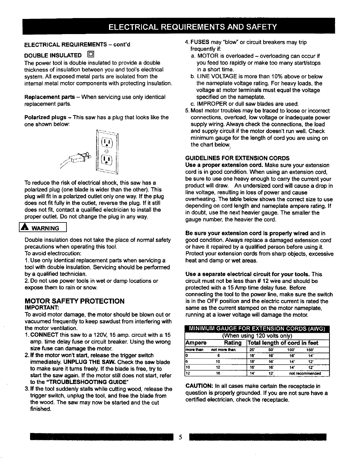
Polarized plugs - This saw has a plugthat lookslike the
one shown below:
-i;222
To reduca the risk of electrical shock, this saw has a
polarized plug (one blade iswider than the other). This
plug will fit in a polarized outlet only one way. If the plug
does not fit fully in the outlet, reverse the plug. If it still
does not fit, contact a qualified electrician to install the
proper outlet. Do not change the plug in any way.
[AWARN,NG]
Double insulationdoes nottake the place of normal safety
precautions when operating this tool.
To avoid electrocution:
1. Use only identical replacement parts when servicinga
toolwith double insulation.Servicing should be performed
by a qualified technician.
2. Do not use power tools inwet or damp locationsor
expose them to rain or snow.
MOTOR SAFETY PROTECTION
IMPORTANT:
To avoid motor damage, the motor shouldbe blownout or
vacuumed frequently to keep sawdust from interfering with
the motor ventilation.
1.CONNECT this saw to a 120V, 15 amp. circuitwitha 15
amp. time delay fuse or circuit breaker. Using the wrong
size fuse can damage the motor.
2. If the motor won't start, release the trigger switch
immediately.UNPLUG THE SAW. Check the saw blade
to make sure it turns freely. If the blade is free, try to
start the sew again. Ifthe motor still does not start, refer
to the "TROUBLESHOOTING GUIDE"
3. If the tool suddenlystalls whilecutting wood, release the
trigger switch, unplugthe tool, and free the blade from
the wood. The saw may now be started and the cut
finished.
4.FUSES may "blow" or circuit breakers may tdp
frequently if:
a. MOTOR is overloaded - overloading can occur if
you feed too rapidly or make too many start/stops
in a short time.
b. LINE VOLTAGE is morethan 10% above or below
the nameplate voltage rating. For heavy loads, the
voltage at motor terminals mustequal the voltage
specified on the nameplate.
c. IMPROPER or dull saw blades are used.
5. Most motor troublesmay be traced to loose or incorrect
connections, overload, lowvoltage or inadequate power
supplywiring.Always check the connections,the load
and supplycircuitif the motor doesn't runwell. Check
minimum gauge for the lengthof cord you are usingon
the chart below.
/
GUIDELINES FOR EXTENSION CORDS
Use a proper extension cord. Make sure yourextension
cord is in good condition.When using an extension cord,
be sure to use one heavy enough to carry the current your
productwill draw. An undersized cord will cause a drop in
linevoltage, resulting in lossof power and cause
overheating. The table below shows the correct sizeto use
depending on cord length and nameplate ampere rating. If
in doubt, use the next heavier gauge. The smaller the
gauge number,the heavier the cord.
Be sure your extension cord is properly wired and in
good condition.Always replace a damaged extension cord
or have it repaired by a qualified person before usingit.
Protect your extension cords from sharp objects, excessive
heat and damp or wet areas.
Use a separate electrical circuit for your tools. This
circuit must not be less than # 12 wire and should be
protected with a 15 Amp time delay fuse. Before
connecting the tool to the power line,make sure the switch
is in the OFF positionand the electric current israted the
same as the current stamped on the motor nameplate,
runningat a lower voltagewilldamage the motor.
lltd I _I liVdlllvJ1¢f_,_1[€t =1 :re] _.i =);,4111:1_k.'f[e] _I[o(I] :| J_l f:VlvL_!
(When using 120 voltsonly)
_mpere Rating Total length of cord in feet
_ore fJlen notmore I_n 25' 50' t00' 150'
6 18' 16' 16' 14'
10 18' 16' 14' 12'
I0 12 16' 16' 14' 12'
12 16 14' 12' not recommended
CAUTION: Inall cases make certain the receptacle in
question is properly grounded. If you are not sure have a
certified electrician, check the receptacle.
5
RECOMMENDED ACCESSORIES
IA, WARNING]
• Use only accessories recommended for this miter saw.
Follow instructions that accompany accessories. Use
of improper accessories may cause hazards.
• The use of any cutting tool except 10 inch saw blades
which meet the requirements under recommended
accessories is prohibited. Do not use accessobes such
as shaper cutters or dado sets. Ferrous metal cutting
and the use of abrasive wheels is prohibited.
• Do not attempt to modify this tool or create
accessories not recommended for use with this tool.
Any such alteration or modification is misuse and could
result in a hazardous condition leading to possible
serious injury.
ACCESSORIES
Visit your Sears Hardware Department or see the Sears
Power and Hand Tool Catalog to purchase recommendec
accessories for this power tool.
[A WARNINGI
To avoid the risk of personal injury, do not modifythis
power tool or use accessories not recommended by Sear
I,A WARNING]
Read warnings and conditionson your CARBIDE TIPPEr
SAW BLADE. Do not operate the saw without the proper
saw blade guard in place. Carbide is a very hard but brittle
material. Care should be taken while mounting, using, and
storingcarbide tipped blades to prevent accidental
damage. Slight shocks, such as striking the tip while
handling, can seriously damage the blade. Foreign objects
in the workpiece, such as wire or nails, can also cause tips
to crack or break off. Before using, always visually
examine the blade and tips for bent teeth, cracks,
breakage, missing or loose tips, or other damage. Do not
use if damage is suspected. Failure to heed safety
instructionsand warnings can result in serious bodily
injury.
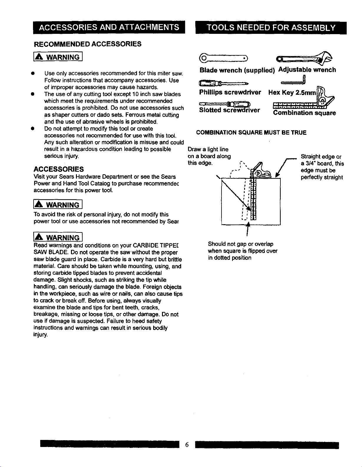
Blade wrench (supplied) Adjustable wrenCh
===J
Phillips screwdriver
_ver
COMBINATION SQUARE MUST BE TRUE
Draw a light line
on a board along
this edge. ,--
s_J
Should not gap or overlap
when square is flipped over
in dotted position
Combination square
Straight edge or
a 3/4" board, this
edge must be
perfectlystraight
I 6
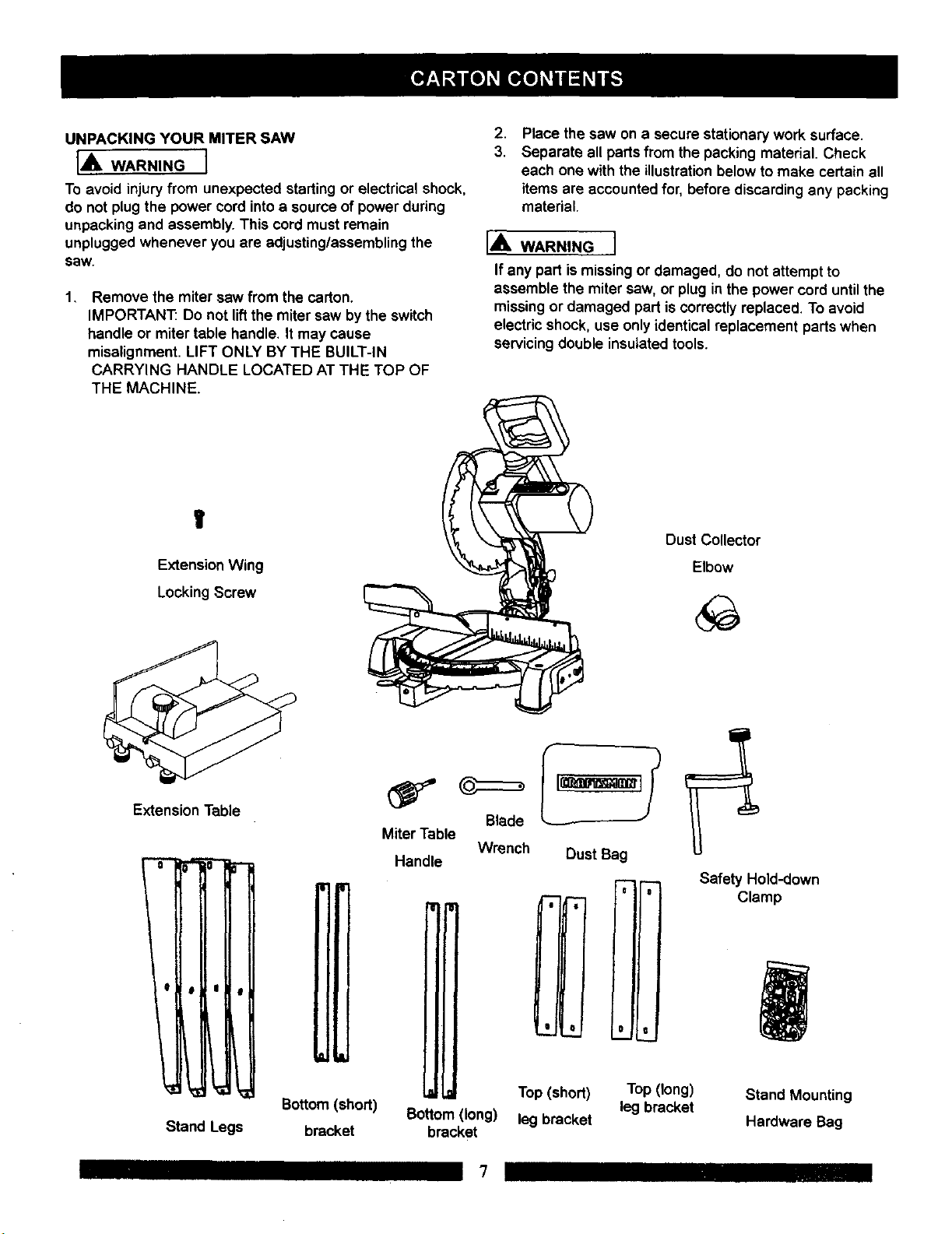
UNPACKING YOUR MITER SAW
IA WARNINGI
To avoid injury from unexpected starting or electrical shock,
do not plugthe power cord intoa sourceof power during
unpacking and assembly. This cord must remain
unplugged whenever you are adjusting/assemblingthe
saw.
1, Remove the miter saw from the carton.
IMPORTANT: Do not liftthe miter saw bythe switch
handle or miter table handle. It may cause
misalignment. LIFT ONLY BY THE BUILT-IN
CARRYING HANDLE LOCATED AT THE TOP OF
THE MACHINE.
V
Extension Wing
.
Place the saw on a secure stationary work surface.
3.
Separate all parts from the packing material. Check
each one with the illustration below to make certain all
items are accountedfor, before discardingany packing
material.
I,_b. WARNING I
If any part is missingor damaged, do not attempt to
assemble the miter saw, or plug in the power cord untilthe
missingor damaged part is correctlyreplaced. To avoid
electricshock, use only identical replacement parts when
servicingdouble insulated tools.
Dust Collector
Elbow
LockingScrew
Extension Table
I
Miter Table
Blade
Handle Wrench Dust Bag
Safety Hold-down
Clamp
,I
Stand Legs
Bottom(short)
bracket
Bottom(long)
bracket
7
Top (short)
leg bracket
Top (long)
leg bracket
Stand Mounting
Hardware Bag
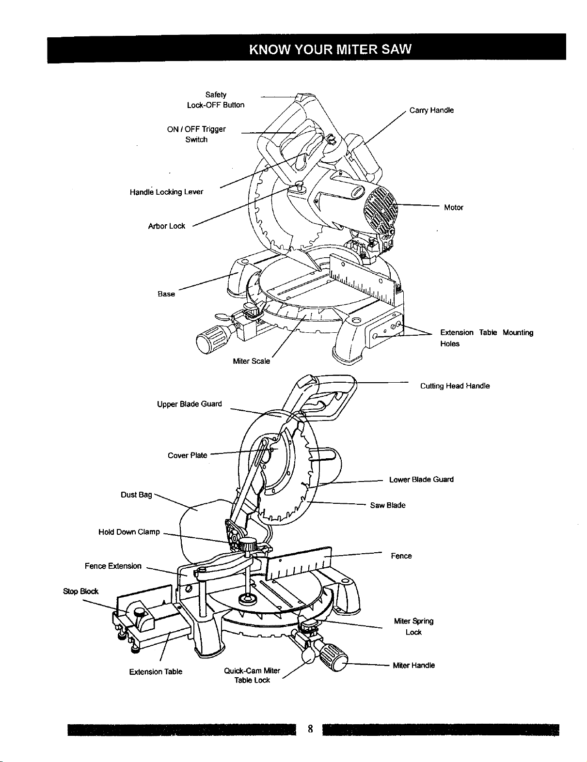
Lock-OFFButton
ON I OFF Trigger
Switch
Handle Locking Lever
Arbor Lock
Base
Safety
' Handle
Motor
ExtensionTable Mounting
Holes
Miter Scale
Fence Extension
StopBlock
Upper Blade Guard
Extension Table
Quick-Cam Miter
Table Lock
Cutting Head Handle
Lower Blade Guard
Saw Blade
Fence
MiferSpdng
Lock
M_rHa_le
CRAFTSMAN COMPOUND MITER SAW TERMS
ARBOR LOCK - Allows the user to keep the blade from
rotating while tightening or loosening the arbor locking
boltduring blade replacement or removal.
BASE - Supports the table, holds accessories and
allows for workbench or leg set mounting.
BEVEL LOCKING HANDLE - Locks the miter saw at a
desired bevel angle.
BEVEL SCALE - To measure the bevel angle of the saw
blade 0° to 45°left.
COVER PLATE SCREW - Loosen this screw and rotate
the plate for access to the blade arbor lockingbolt.
STOP LATCH - Locks the miter saw in the lowered
positionfor compact storageand transportation.
SWITCH HANDLE - The cutting head handle contains
the trigger switch and a safety lock-off slide switch. The
blade is lowered into the workpiece by pushing down on
the handle. The saw will return to its upright position
when the handle is released.
WARNING LABELS - Read and understand for your
own safety. Always make certain these are in place &
legible.
WRENCH STORAGE - Convenient storage to prevent
misplacing the blade wrench.
WOODWORKING TERMS
DUST CHUTE - Exhausts debds away from the user.
EXTENSION TABLE - Extends the width of the work
table for support while cutting long work pieces. They
can be used with or without a stop block as an additional
side fence.
FENCE - Helps to keep the workpiece from moving
when sawing. Scaled to assist with accurate cutting.
HAND HOLD - For movingthe saw when unplugged.
SAFETY LOCK-OFF SLIDE SWITCH - Yellow buttonon
handle must be pushed forward to activate the trigger
switch.
LOWER BLADE GUARD - Helps protect your hands
from the blade in the raised position, it retracts as the
blade is lowered.
MITER HANDLE - Used to lock and unlock the miter
table, and to rotate the saw to a right or left cutting
position.
MITER SCALE - To measure the miter angle 0° to 45°
left, 0° to 45° dght.
MITER SPRING LOCK - Used in combination with the
miter handle, it locks the miter saw at a preset positive
stop for the desired miter angle.
MOUNTING HOLES - To mount the miter saw to a
stable surface.
ON/OFF TRIGGER SWITCH - To prevent the tdgger
from being accidentally engaged, a lock-off slide switch
is provided. To start the tool, push the lock-off slide
switch forward and squeeze the trigger. Release the
tdgger to stop the miter saw.
ARBOR - The shaft on which a blade is mounted,
BEVEL CUT - An angle cut made through the face of
the workpiece.
COMPOUND CUT -A simultaneous bevel and miter cut.
CROSS CUT - A cut made across the width or grain of
the workpiece.
FREEHAND - Performing a cut without using a fence
(guide), hold down or other proper device to prevent the
workpiece from twistingduringthe cuttingoperation.
GUM -A stickysap from wood products.
HEEL- Misalignmentof the blade.
KERF - The amount of material removed by blade cut.
MITER CUT - An angle cut made across the width or
grain of the workpiece.
RESIN -A stickysap that has hardened.
REVOLUTIONS PER MINUTE (RPM) - The number of
turns completed by a spinningobject in one minute.
SAW BLADE PATH - The area of the workpiece or table
top directly in line with the travel of the blade Or the part
of the workpiece which will be cut.
SET - The distance between two saw blade tips, bent
outward in opposite directions to each other. The further
apart the tips are, the greater the set.
WORKPIECE - The item being cut. The surfaces of a
workpiece are commonly referred to as faces, ends, and
edges.
9
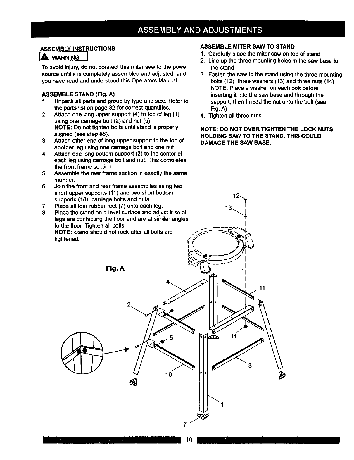
ASSEMBLY INSTRUCTIONS
IA WARNINGI
To avoid injury,do not connect this miter saw to the power
source untilit is completely assembled and adjusted, and
you have read and understood this Operators Manual.
ASSEMBLE STAND (Fig. A)
1. Unpack all parts and group by type andsize. Refer to
the parts list on page 32 for correct quantities.
2. Attach one long upper support(4) to topof leg (1)
usingone carriage bolt (2) and nut (5).
NOTE: Do not tighten bolts untilstand is propedy
aligned (see step#8).
3. Attach other end of long upper support to the top of
another leg usingone carriage bolt and one nut.
4. Attach one long bottom support (3) to the center of
each leg using carriage bolt and nut. This completes
the front frame section.
5. Assemble the rear frame sectionin exactly the same
manner.
6. Join the front and rear frame assemblies usingtwo
short upper supports (11) and two shortbottom
supports (10), carriage bolts and nuts.
7. Place all four rubber feet (7) onto each leg.
8. Place the stand on a level surface and adjust it soall
legs are contactingthe floor and are at similarangles
to the floor.Tighten all bolts.
NOTE: Stand should not rock after all bolts are
tightened.
ASSEMBLE MITER SAW TO STAND
1. Carefully place the miter saw on top ofstand.
2. Line up the three mountingholes inthe saw base to
the stand.
3. Fasten the saw tothe stand using the three mounting
bolts(12), three washers (13) and three nuts (14).
NOTE: Place a washer on each bolt before
insertingit into the saw base and throughthe
support, then thread the nut onto the bolt(see
Fig. A)
4. Tighten all three nuts.
NOTE: DO NOT OVER TIGHTEN THE LOCK NUTS
HOLDING SAW TO THE STAND. THIS COULD
DAMAGE THE SAW BASE.
12
Fig. A
10
11
5
14
1
]0
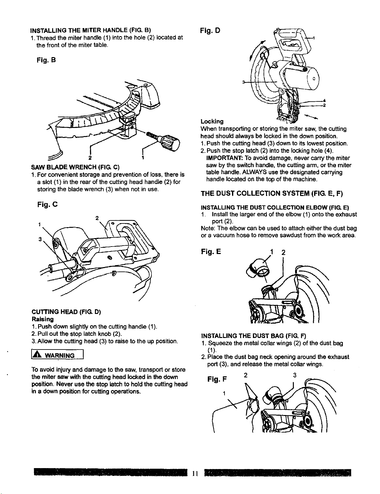
INSTALLING THE MITER HANDLE (FIG. B)
1,Thread the miter handle (1) into the hole (2) located at
the front of the mitertable.
Fig. B
2 1
SAW BLADE WRENCH (FIG. C)
1.For convenient storage and prevention of loss, there is
a slot (1) inthe rear of the cutting head handle (2) for
storing the blade wrench (3) when not in use.
Fig. D
Locking
When transporting or storing the miter saw, the cutting
head shouldalways be locked inthe downposition.
1.Push the cuttinghead (3) downto its lowest position,
2,Push the stop latch(2) intothe locking hole (4).
IMPORTANT: To avoiddamage, never carry the miter
saw by the switch handle, the cuttingarm, or the miter
table handle, ALWAYS use the designated carrying
handle located on the top ofthe machine.
THE DUST COLLECTION SYSTEM (FIG. E, F)
Fig. C
2
1
3
CUTTING HEAD (FIG. D)
Raising
1.Push down slightlyon the cutting handle (1).
2. Pull out the stop latch knob (2).
3.Allow the cutting head (3) to raise to the up position.
IA WA ,NGI
To avoid injuryand damage to the saw, transport or store
the miter saw with the cutting head locked in the down
position. Never use the stop latch to hold the cutting head
in a down position for cutting operations.
INSTALLING THE DUST COLLECTION ELBOW (FIG. E)
1. Install the larger end of the elbow (1) onto the exhaust
port (2).
Note: The elbow can be used to attach either the dust bag
or a vacuum hose to remove sawdust from the work area.
Fig. E 1 2
INSTALLING THE DUST BAG (FIG. F)
1. Squeeze the metal collar wings (2) of the dust bag
(1).
2, Place the dust bag neck opening around the exhaust
port (3), and release the metal collarwings,
2 3
Fig. F
IIIIIlllllll !_
 Loading...