

Craftsman 137228010 Owner’s Manual
Owner's anual
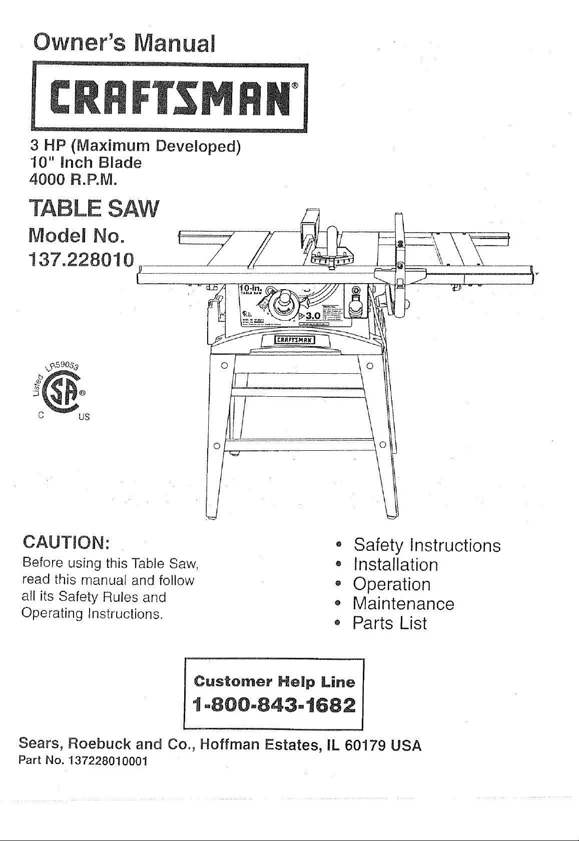
3 HP (Maximum Developed)
10" inch B_ade
4000 R.P.M.
"TABLE SAW
Model No.
137.228010
C US
CAUTION:
Before using this Table Saw,
read this manual and follow
all its Safety Rules and
Operating Instructions.
• Safety Instructions
• Installation
,, Operation
o Maintenance
o Parts List
Customer Help Line
1-800=843=t682
Sears, Roebuck and Co., Hoffman Estates, IL 60179 USA
Part No. 137228010001
SECTION PAGE
Warranty ................................................................ 2
Product Specifications ..................................................... 2
Safety Instructions ........................................................ 3
Accessories and Attachments ............................................... 6
Tools needed for assembly ................................................. 6
Carton Contents .......................................................... 6
Know Your Table Saw ...................................................... 8
Assembly and Adjustments ................................................. 9
Operation .............................................................. 16
Maintenance ............................................................ 20
Troubleshooting guide .................................................... 21
Parts .................................................................. 22
Making a push stick ....................................................... 33
FULL ONE YEAR WARRANTY
If this product fails due to a defect in material or workmanship within one year from the date of purchase, Sears
will repair it free of cha_rge.
Contact a Sears Service Center for repair.
If this product is used for commercial or rental purposes, this warranty applies only for 90 days from the date of
purchase.
This warranty gives you specific legal rights, and you may also have other rights which vary from state to state.
Sears, Roebuck and Co., Dept. 817 WA, Hoffman Estates, IL 60179
MOTOR
Maximum developed HP ........ 3.0
Type ....................... Universal
Volts ....................... 120
Amperes .................... 15
Hertz ....................... 60
RPM (no load) ................ 4000
Overload protection ............ Yes
SAW
Table ....................... 25-3/16" x 21-1/4"
Extension rails ................ 2 (Right & Left)
Extension rip capacity .......... 24-1/2" (Right)
Blade ....................... 10"
Rip scale ................... Yes
Rip fence .................... Yes
Miter gauge .................. Yes
Leg set ..................... Yes
Maximum cutting depth at 90° .... 3"
Maximum cutting depth at 45° .... 2"
Maximum width of dado ........ 13/16"
Weight ...................... 75 Lb.
To avoid electrica! hazards, fire hazards, or damage to
the tool, use proper circuit protection.
Your table saw is wired at the factory for 120V operation.
Connect to a 120V, 15 AMP branch circuit and use a 15
AMP time delay fuse or circuit breaker. To avoid shock or
• fire, replace power cord immediately if it is worn, cut or
damaged in any way.
GENERAL SAFETY INSTRUCTIONS
BEFORE USING THE TABLE SAW
Safety is a combination of common sense, staying alert
and knowing how to use your table saw.
To avoid mistakes that could cause serious injury, do not
plug the table saw in until you have read and understood
the following:
.
READ and become familiar with this entire instruction
manual. LEARN the tool's applications, limitations, and
possible hazards.
.
KEEP GUARDS IN PLACE and in working order.
3.
REMOVE ADJUSTING KEYS AND WRENCHES.
Form the habit of checking to see that keys and
adjusting wrenches are removed from the tool before
turning ON.
,
KEEP WORK AREA CLEAN. Cluttered areas and
benches invite accidents.
.
DON'T USE IN A DANGEROUS ENVIRONMENT.
Don't use power tools in damp or wet locations, or
expose them to rain. Keep work area well lighted.
,
KEEP CHILDREN AWAY. All visitors should be kept at
a safe distance from the work area.
7.
MAKE WORKSHOP KID PROOF with padlocks, master
switches, or by removing starter keys.
8.
DON'T FORCE THE TOOL, It will do the job better
and safer at the rate for which it was designed.
9.
USE THE RIGHT TOOL. Don't force tool or the
attachment to do a job for which it was not designed.
10.
USE PROPER EXTENSION CORD. Make sure your
extension cord is in good condition. When using an
extension cord, be sure to use one heavy enough to
carry the current your product will draw. An undersized
cord will cause a drop in line voltage resulting in loss
of power and overheating. The table on page 5 shows
the correct size to use depending on cord length and
nameplate ampere rating. If in doubt, use the next
heavier gauge. The smaller the gauge number, the
heavier the cord.
11.
WEAR PROPER APPAREL. DO NOT wear loose
clothing, gloves , neckties, rings, bracelets, or other
jewelry which may get caught in moving parts.
Nonslip footwear is recommended. Wear protective
hair covering to contain long hair.
SAVE THESE
12.
13.
14.
15.
16. REDUCE THE RISK OF UNINTENTIONAL STARTING.
17. USE RECOMMENDED ACCESSORIES. Consult the
18. NEVER STAND ON TOOL. Serious injury could occur
19. CHECK FOR DAMAGED PARTS. Before further use of
20. NEVER LEAVE TOOL RUNNING UNATTENDED.
21.
22. MAINTAIN TOOLS WITH CARE. Keep tools sharp
23. DIRECTION OF FEED. Feed work into a blade or
WEARYOUR ALWAYS WEAR EYE
PROTECTION. Any table
saw can throw foreign
objects into the eyes which
could cause permanent eye
damage. ALWAYS wear
Safety Goggles (not glasses)
that comply with ANSI safety standard Z87.1.
Everyday eyeglasses have only impact-resistant
lenses. They ARE NOT safety glasses. Safety
Goggles are available at Sears. NOTE: Glasses or
goggles not in compliance with ANSI Z87.1 could
seriously hurt you when they break.
WEAR A FACE MASK OR DUST MASK.
Sawing operation produces dust.
SECURE WORK. Use clamps or a vise to hold work
when practical. It's safer than using your hand and it
frees both hands to operate tool.
DISCONNECT TOOLS before servicing, and when
changing accessories, such as blades, bits, cutters,
and the like.
Make sure the switch is in OFF position before
plugging in.
owner's manual for the recommended accessories.
The use of improper accessories may cause risk of
injury to persons.
if the tool is tipped or if the cutting tool is unintentionally
contacted.
the tool, a guard or other part that is damaged should
be carefully checked to determine that it will operate
properly and perform its intended function. Check for
alignment of moving parts, binding of moving parts,
breakage of parts, mounting, and any other conditions
that may affect its operation. A guard or other part that
is damaged should be properly repaired or replaced.
TURN THE POWER OFF. Don't leave the tool until
it comes to a complete stop.
DON'T OVERREACH. Keep proper footing and
balance at all times.
and clean for best and safest performance. Follow
instructions for lubricating and changing accessories.
cutter against the direction of rotation of the blade or
cutter only.
INSTRUCTIONS
24. WARNING: Dust generated from certain materials can 14. AVOID AWKWARD OPERATIONS and hand
be injurious to your health. Always operate saw in well positions where a sudden slip could cause your hand
ventilated areas and provide for proper dust removal, to move into the cutting tool.
15.
SPECiFiC SAFETY iNSTRUCTiONS
FOR THE TABLE SAW
NEVER USE SOLVENTS to clean plastic parts.
Solvents could possibly dissolve or otherwise
damage the material. Only a soft damp cloth should
be used to clean plastic parts.
.
ALWAYS USE SAW BLADE GUARD spreader and
anti-kickback pawls for every operation for which 16.
they can be used, including through-sawing.
Through-sawing operations are those in which the 17.
blade cuts completely through the workpiece
MOUNT your table saw before performing any
cutting operations. Refer to installation instructions.
NEVER CUT METALS or materials which may make
hazardous dust.
when ripping or cross-cutting.
18.
,
ALWAYS HOLD THE WORK FIRMLY against the
miter gauge or rip fence.
3.
USE A PUSH STICK when required. Always use a
push stick for ripping narrow stock. Refer to ripping
applications in the instruction manual where the 19.
push stick is covered in detail. See the push stick
ALWAYS USE IN A WELL VENTILATED AREA.
Remove sawdust frequently. Clean out sawdust
from the interior of the saw to prevent a potential
fire hazard. Attach a vacuum to the dust chute for
additional sawdust removal.
NEVER LEAVE THE TOOL running unattended.
Don't leave the tool until it comes to a complete stop.
pattern included in this Owner's Manual.
20.
,
NEVER PERFORM ANY OPERATION
"FREE HAND", which means using your hands
only to support or guide the workpiece. Always
use either the fence or the miter gauge to position
and guide the work.
5,
NEVER STAND or have any part of your body
in line with the path of the saw blade. Keep your
hands out of the line of the saw blade.
6. NEVER REACH behind or over the cutting tool
for any reason.
7. REMOVE the rip fence when cross-cutting.
For proper operation follow the instructions of this
owner's manual titled "SAW MOUNTED TO WORK
SURFACES." Failure to provide sawdust fall-through
and removal hole will allow sawdust to build up in the
motor area, which may result in a fire hazard or
cause motor damage.
21.
ALWAYS USE THE TABLE EXTENSION for extra
support when cutting a long workpiece.Never use
another person or any unstable surface to hold long
workpiece.
22.
ALWAYS LOCK THE TABLE EXTENSION securely
in place before cutting workpiece.
8. DO NOT USE molding head set with this saw.
9. FEED WORK INTO THE BLADE against the
ELECTRICAL REQUIREMENTS
direction of rotation only.
10. NEVER use the fence as a cut-off gauge when
cross-cutting.
POWER SUPPLY AND MOTOR
SPECIFICATIONS
11. NEVER ATTEMPTTO FREE A STALLED SAW
BLADE without first turning the saw OFR Turn
power switch OFF immediately to prevent motor
damage.
To avoid electrical hazards, fire hazards, or damage to
the tool, use proper circuit protection. Use a separate
electrical circuit for your toots.Your saw is wired at the
12. PROVIDE ADEQUATE SUPPORT to the rear and
sides of the saw table for wide or long workpieces.
factory for 120V operation. Connect to a 120V, 15 Amp
circuit and use a 15 Amp time delay fuse or circuit
breaker. To avoid shock or fire, if power cord is worn or
13. AVOID KICKBACKS (work thrown back towards
you) by keeping the blade sharp, keeping the rip
cut, or damaged in any way, have it replaced
immediately.
fence parallel to the saw blade, and by keeping the
spreader, anti-kickback pawls, and guard in place
and functioning. Do not release work before it is
pushed all the way past the saw blade. Do not rip
work that is twisted, warped, or does not have a
straight edge to guide along the fence.
GROUNDING INSTRUCTIONS
INTHE EVENT OF A MALFUNCTION OR BREAKDOWN,
grounding provides a path of least resistance for electric
current and reduces the risk of electric shock. This tool
is equipped with an electric cord that has an equipment
grounding conductor and a grounding plug. The plug
MUST be plugged into a matching receptacle that is
properly installed and grounded in accordance with ALL
local codes and ordinances.
DO NOT MODIFYTHE PLUG PROVIDED. If it will not
fit the receptacle, have the proper receptacle installed
by a qualified electrician.
IMPROPER CONNECTION of the equipment grounding
conductor can result in risk of electric shock. The
conductor with the green insulation (with or without
yellow stripes) is the equipment grounding conductor. If
repair or replacement of the electric cord or plug is
necessary, DO NOT connect the equipment grounding
conductor to a live terminal.
CHECK with a qualified electrician or service person if
you do not completely understand the grounding
instructions, or if you are not sure the tool is properly
grounded.
USE A SEPARATE ELECTRICAL CIRCUIT for your
tools. This circuit must not be less than #12 wire and
should be protected with a 15 Amp time delay fuse.
Before connecting the motor to the power line, make
sure the switch is in the OFF position and the electric
current is rated the same as the current stamped on the
motor nameplate. Running at a lower voltage will
damage the motor.
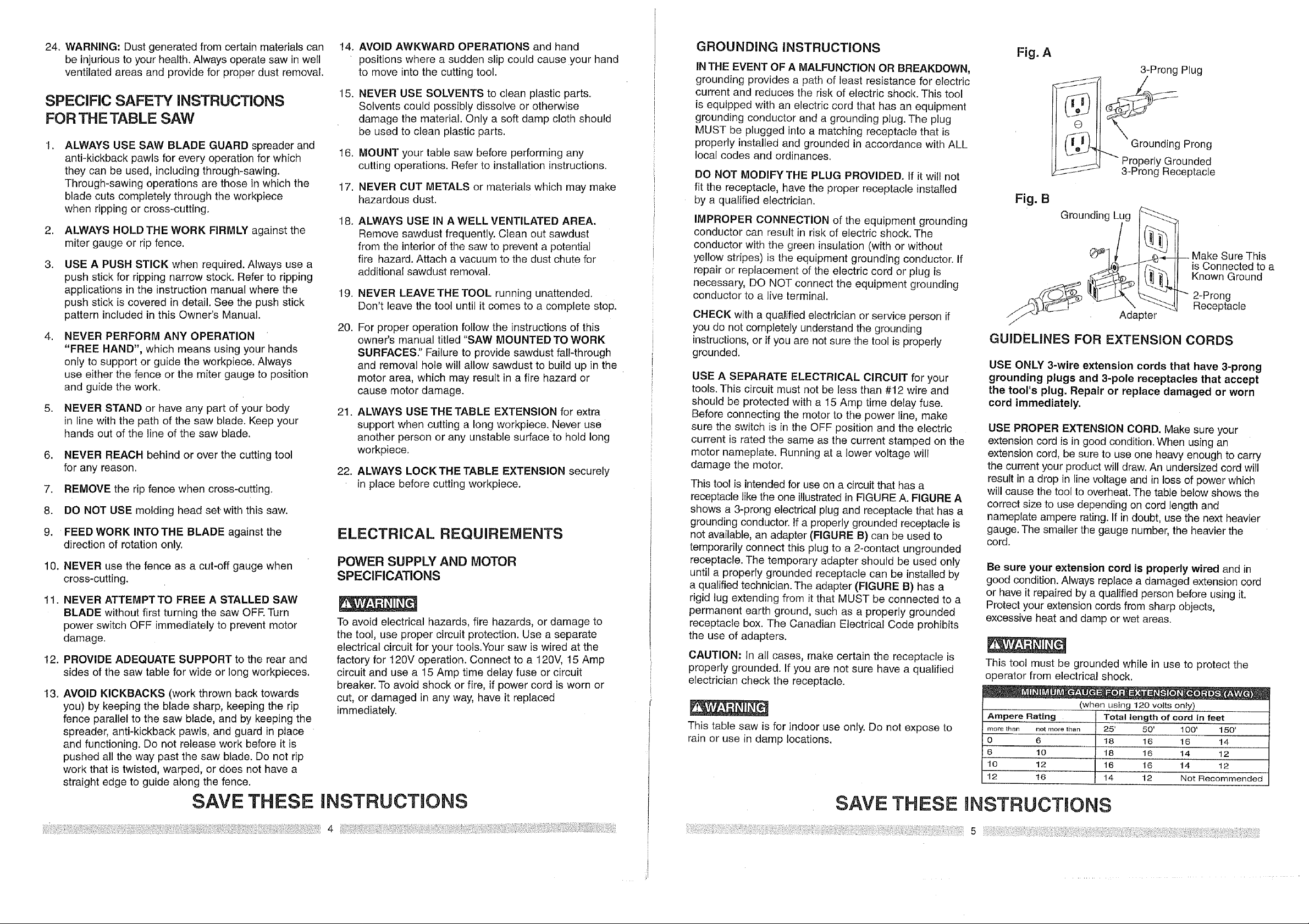
This tool is intended for use on a circuit that has a
receptacle like the one illustrated in FIGURE A. FIGURE A
shows a 3-prong electrical plug and receptacle that has a
grounding conductor. Ifa properly grounded receptacle is
not available, an adapter (FIGURE B) can be used to
temporarily connect this plug to a 2-contact ungrounded
receptacle. The temporary adapter should be used only
until a properly grounded receptacle can be installed by
a qualified technician. The adapter (FIGURE B) has a
rigid lug extending from it that MUST be connected to a
permanent earth ground, such as a properly grounded
receptacle box. The Canadian Electrical Code prohibits
the use of adapters.
CAUTION: In all cases, make certain the receptacle is
properly grounded. If you are not sure have a qualified
electrician check the receptacle.
This table saw is for indoor use only. Do not expose to
rain or use in damp locations.
Fig. A
3-Prong Plug
Q
[ fo! )._ Grounding Prong
'_/- "'" Properly Grounded
J_-JJ-/ 3-Prong Receptacle
Fig. B
Grounding Lug
Make Sure This
is Connected to a
Known Ground
2-Prong
Receptacle
GUIDELINES FOR EXTENSION CORDS
USE ONLY 3-wire extension cords that have 3-prong
grounding plugs and 3-pole receptacles that accept
the tool's plug. Repair or replace damaged or worn
cord immediately.
USE PROPER EXTENSION CORD. Make sure your
extension cord is in good condition. When using an
extension cord, be sure to use one heavy enough to carry
the current your product will draw. An undersized cord will
result in a drop in line voltage and in loss of power which
will cause the tool to overheat. The table below shows the
correct size to use depending on cord length and
nameplate ampere rating. If in doubt, use the next heavier
gauge. The smaller the gauge number, the heavier the
cord.
Be sure your extension cord is properly wired and in
good condition. Always replace a damaged extension cord
or have it repaired by a qualified person before using it.
Protect your extension cords from sharp objects,
excessive heat and damp or wet areas.
This tool must be grounded while in use to protect the
operator from electrical shock.
(when using 120 volts only)
Ampere Rating
more than not more than
0 6
6 10
10 12
12 16
Totallength ofcord in feet
25' 50' 100' 150'
18 16 16 !4
18 16 14 12
16 16 14 12
14 12 Not Recommended
SAVE THESE INSTRUCTmONS
SAVE THESE NSTRUCT ONS
UNPACKING YOUR TABLE SAW:
RECOMMENDED ACCESSORMES
Visit your Sears Hardware Department or see the
Craftsman Power and Hand Tools Catalog to purchase
recommended accessories for this power tool.
To avoid the risk of personal injury:
o Do not use adjustable (wobble) type dadoes or
carbide tipped dado blades, maximum dado width
is 13/16".
Do not use a dado with a diameter larger than 6".
o Do not use molding head set with this saw.
Do not modify this power tool or use accessories not
recommended by Sears.
TOOLS NEEDED
#2 Phillips screwdriver
Adjustable wrench
f-Illlll
Straight edge
Combinationsquare
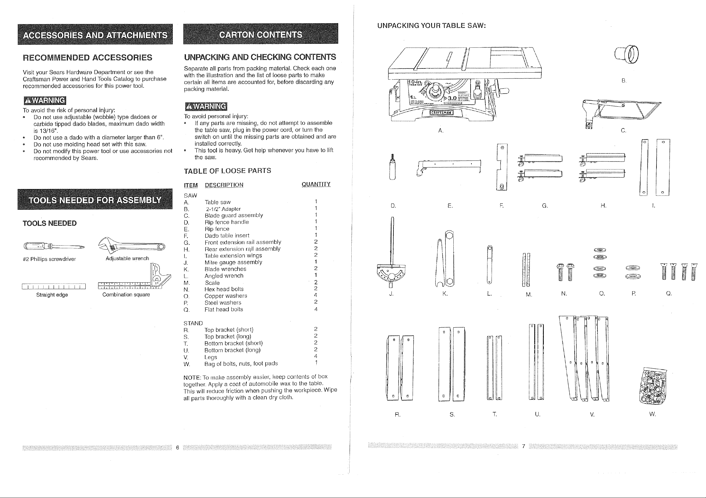
UNPACKING AND CHECKMNG CONTENTS
Separate all parts from packing material. Check each one
with the illustration and the list of loose parts to make
certain all items are accounted for, before discarding any
packing material.
To avoid personal injury:
If any parts are missing, do not attempt to assemble
the table saw, plug in the power cord, or turn the
switch on until the missing parts are obtained and are
installed correctly.
This tool is heavy. Get help whenever you have to lift
the saw.
TABLE OF LOOSE PARTS
ITEM DESCRIPTION QUANTITY
SAW
A. Table saw 1
B. 2-1/2" Adapter 1
C. Blade guard assembly 1
D. Rip fence handle I
E. Rip fence 1
R Dado table insert 1
G. Front extension rail assembly 2
H. Rear extension rqil assembly 2
I. Table extension wings 2
J. Milre gauge assembly 1
K. Blade wrenches 2
L. Angled wrench 1
M. Scale 2
N. Hex head bolts 2
O. Copper washers 4
R Steel washers 2
Q. Flat head bolts 4
A.
D. E.
J. K.
S.
"S" -S-
t
1
O
e_
m.
O, R Q.
STAND
R. Top bracket (short)
S. Top bracket (long)
T. Bottom bracket (short)
U. Bottom bracket (long)
V. Legs
W. Bag of bolts, nuts, foot pads
NOTE: To make assembly easier, keep contents of box
together. Apply a coat of automobile wax to the table.
This will reduce friction when pushing the workpiece. Wipe
all parts thoroughly with a clean dry cloth.
2
2
2
2
4
1
(3
0
I
L
t3
R. S. T. U. V.
Extensionwing
Ripfence
mitergauge
storage
Bladetilt
pointer
Mounlingholes
Blade
scale
Bladeguard
Milergauge
Extensionrail
!
Table
extensionlock
Ripscale
Bladetiltinghandwheel
Overloadresetswitch
ON/OFFswitchwithsafetykey
Powercord
Stand
Blade Kickback
pawls
Splitter
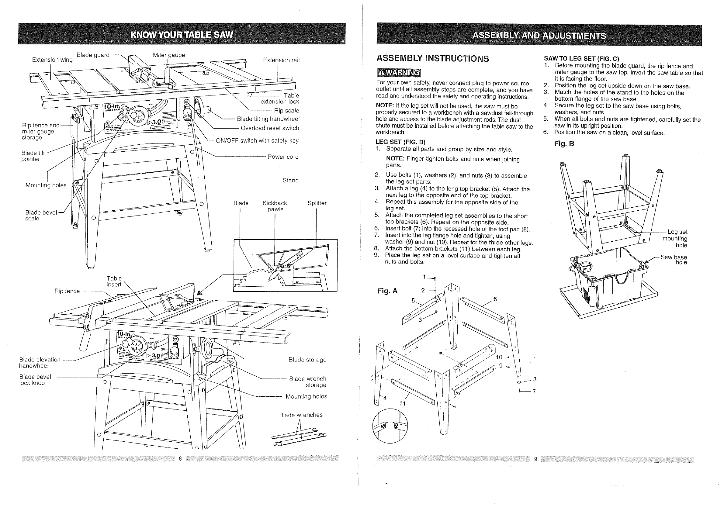
ASSEMBLY JNSTRUCTUONS
For your own safety, never connect plug to power source
outlet until all assembly steps are complete, and you have
read and understood the safety and operating instructions.
NOTE: If the leg set will not be used, the saw must be
properly secured to a workbench with a sawdust fall-through
hole and access to the blade adjustment rods. The dust
chute must be installed before attaching the table saw to the
workbench.
LEG SET (FIG. B)
1. Separate al! parts and group by size and style.
NOTE: Finger tighten bolts and nuts when joining
parts.
2. Use bolts (1), washers (2), and nuts (3) to assemble
the leg set parts.
3. Attach a leg (4) to the long top bracket (5). Attach the
next leg to the opposite end of the top bracket.
4. Repeat this assembly for the opposite side of the
leg set.
5. Attach the completed leg set assemblies to the short
top brackets (6). Repeat on the opposite side.
,
Insert bolt (7) into the recessed hole of the foot pad (8).
7.
i
i 8.
Insert into the leg flange hole and tighten, using
washer (9) and nut (10). Repeat for the three other legs.
Attach the bottom brackets (11) between each leg.
9.
Place the leg set on a level surface and tighten all
nuts and bolts.
SAW TO LEG SET (FIG. C)
1. Before mounting the blade guard, the rip fence and
miter gauge to the saw top, invert the saw table so that
it is facing the floor.
2. Position the leg set upside down on the saw base.
3. Match the holes of the stand to the holes on the
bottom flange of the saw base.
4. Secure the leg set to the saw base using bolts,
washers, and nuts.
5. When all bolts and nuts are tightened, carefully set the
saw in its upright position.
6. Position the saw on a clean, level surface.
Fig. 8
set
mounting
hole
base
hole
Blade elevation
handwhee!
Blade bevel
lock knob
Ripfence--
Table
insert
Blade storage
-- BEade wrench
storage
Mounting holes
Blade wrenches
Fig. A 2
?
11

SAWMOUNTED TO OTHER WORK SURFACES (FIG. C)
To avoid fire hazard and possible injury:
- The choice of work surface should provide access to
the area under the saw housing. The blade regulating
rods need to be adjusted and maintained, and
sawdust accumulation prevented.
o Attach a vacuum hose to the dust chute to facilitate
sawdust removal.
1. If the leg set will not be used the saw must be properly
secured to a sturdy workbench using the four mounting
holes at the base of the saw.
2. The surface of the table where the saw is to be
mounted must have a hole large enough to facilitate
sawdust fall-through and removal.
3. Square the saw on the mounting surface and mark
the location of the four 3/8" mounting holes (1).
4. Drill 3/8" holes into the mounting surface.
5. Mark a 12" to 14" square (2) centered between the
four mounting holes (1).
6. Cut out and remove the square.
7. This opening will allow sawdust to fal! through
the saw base.
8. Place the saw on the work surface, and align the
mounting holes of the saw with those drilled through
the surface.
g. Fasten the saw to the work surface.
FJg. C
@
2
@----1
EXTENSION WINGS AND RAILS (FIG. D, E)
NOTE: There are two extension support rails shaped to
match the front table rail and two extension support rails
shaped to match the rear table rail.
Install the support rails (FIG. D)
1. Match the extension rail (1) shape to the front and
rear table rails (2).
2. Push the bracket assemblies (3) firmly into the ends of
the table rails, sliding the flats of the bracket and the
bolts into the rail slots.
3. Place a combination square ruler across a table rail and
one extension support rail.
4. If lhe rail is not level with the table rail, adjust the
bolts (4) and rails. When the rail is level and snug,
tighten the lock knob (5).
5. Repeat this procedure for all extension support rails.
Fig. D
Install the extension wing (FIG. E)
1. Place tile extension wing (1) on the rails, aligning with
the holes in each rail (2).
2. Thread screws (3) into each hole and tighten.
3. Place a straight ruler on the extension wing and table
and measure the alignment, front and rear. It should
be parallel tothe edge of the table top, and flat.
4. If the alignment of the wing to the table is not correct,
loosen the screws and adjust its position.
Tighten the screws And check the alignment again.
5. Stick the scale (5) on the front extension rail, right and left.
Fig. E
H 3
I
I
I
i I
Installing or removing the table extensions (FIG. E)
NOTE: When the extension wing assemblies are complete,
they may be removed or installed quickly and easily.
To remove, loosen the two lock knobs (4), front and rear.
Pull the entire wing assembly out of the table rails.
To install, push the wing assembly support rails into the
table rails firmly. Tighten both lock knobs.
i
I
4
BLADE GUARD ASSEMBLY (FIG. F, G, H)
To avoid injury:
o From an accidental start, make sure the switch is in
the OFF position and the plug is not connected to the
power source outlet.
o When changing any blade or installing the blade
guard, cover the blade teeth with folded cardboard.
, From a thrown workpiece, thrown blade parts, or
blade contact, never operate the saw without the
proper table insert in place. Always use the blade
insert when sawing and the dado insert when using
a dado.
Remove the table insert (FIG. F)
1. Loosen and remove the front and rear thumb-nuts (1)
from under the table insert (2).
2. Unscrew the two screws (3) from the top and remove
the table insert.
o
I
I
To avoid injury from an accidental start, make sure the
switch is in the OFF position and the plug is not
connected to the power source outlet.
Installing the blade guard assembly (FIG. G)
1. Remove table insert.
2. Unlock the blade bevel lock knob (1).
3. With the blade elevation handwheel (2), raise the
blade to the maximum height.
4. Using the blade tilting handwheel (3), tilt the blade
to 45 ° on the bevel scale.
5. Lock the blade tilt locking knob.
6. Locate the splitter assembly mounting bracket (4) in
back of the blade.
7. Cover the blade teeth with a folded cardboard or
position the plastic blade guard over the blade to
protect your hands.
8. Place the two kickback pawls (5) toward the rear of
the table, and align the splitter mounting holes to the
holes in the bracket.
9. Place the steel flat washers (6) on the two bolts (7)
and thread the bolts into the holes.
I0. Tighten the bolts with the angled wrench.
Fig. G
4
5
Aligning the blade guard splitter (FIG. H)
NOTE: The splitter must always be correctly aligned with
the blade so the cut workpiece will pass on _ither side
without binding or twisting.
Peel offthe paper on the copper washer (5) before placing itto
the side of splitter (2). Stick it to the splitter (2) if the align[nent
is needed.
1. Remove table insert.
2. Lift the blade guard and position toward the rear of
the table.
3. Raise the blade to the 90°vertical position by
unlocking the blade tilt lock and turning the tilting
handwheel. Lock the tilt lock.
4. To see if the blade (1) and splitter (2) are correCtly
aligned, lay a combination square along the side of
and against the blade and splitter.
5. Tilt the blade to the 45°position and check the
alignment again.
6. If the blade and splitter are not correctly aligned,
loosen and remove the two bolts (3) and two
washers (4) from the mounting bracket.
7. Reassemble, placing a copper washer (5) on the bolts
on the side of the splitter bracket before assembling
to the mounting bracket (6). The additional washer will
be between the two brackets, changing the alignment.
8. To tilt the splitter to the left, place the washer on the
bottom bolt. To tilt the splitter right, place the copper
washer on the top bolt.
9. Tighten the bolts and check the splitter and blade
alignment again.
10. Add or remove washers until the alignment is correct.
11. Replace the table insert.
 Loading...