

Craftsman 12632563 Owner’s Manual

Operators Manual
CRItFTSMI:INi
7-1/4 IN. SLIDING MITER SAW
MODEL NO. 126.32563
CAUTION:
Before using this Miter Saw,
read this manual and follow
all its Safety Rules and
Operating Instructions.
Sears Brands Management Corporation, Hoffman Estates, IL 60179 U.S.A.
Visit our Craftsman website: www.craftsman.com
Part No: 3848234
• Safety Instructions
• Installation
• Operation
• Maintenance
• Troubleshooting
• Parts List
• Espa_ol

SECTION PAGE
Warranty .................................................................................................................................... 2
Product Specifications ............................................................................................................... 3
Symbols ..................................................................................................................................... 4
Power Tool Safety ...................................................................................................................... 5
Sliding Miter Saw Safety ............................................................................................................ 7
Electrical Requiretments and Safety .......................................................................................... 9
Accessories and Attachments ................................................................................................. 11
Tools Needed For Assembly .................................................................................................... 12
Carton Contents ...................................................................................................................... 13
Know Your Sliding Miter Saw ................................................................................................... 14
Glossary of Terms .................................................................................................................... 16
Assembly and Adjustments ..................................................................................................... 18
Operation ................................................................................................................................. 26
Maintenance ............................................................................................................................ 36
Troubleshooting Guide ............................................................................................................ 38
Parts List .................................................................................................................................. 40
CRAFTSMAN ONE YEAR FULL WARRANTY
FOR ONE YEAR from the date of purchase, this product is warranted against defects
in material or workmanship. A defective product will receive free or replacement if repair is
unavailable. For warranty coverage details to obtain free repair or replacement,
visit the web site: www.craftsman.com
This warranty does not cover the blade which is an expendable part that can wear out
from normal use within the warranty period. This warranty is void if this product isever
used while providing commercial services or if rented to another person. This warranty
gives you specific legal rights, and you may also have other rights which vary from state to state.
Sears Brands Management Corporation, Hoffman Estates, IL 60179
,_ WARNING l
Some dust created by using power tools contains chemicals known to the state of California
to cause cancer and birth defects or other reproductive harm. Some examples of these
chemicals are: • Lead from lead-based paints
• Crystalline silica from bricks, cement and other masonry products
• Arsenic and chromium from chemically treated lumber
Your risk from these exposures varies, depending on how often you do this type of work. To
reduce your exposure to these chemicals, work in a welt ventilated area and work with approved
safety equipment such as dust masks that are specially designed to filter out microscopic particles.
2

MOTOR
PowerSource.....................................................................................................120V,60Hz,9A
Speed.........................................................................................................50OORPM(NoLoad)
Brake...............................................................................................................................Electric
DoubleInsulated....................................................................................................................Yes
BLADESIZE
Diameter.........................................................................................................................7-1/4in.
Arborsize..........................................................................................................................5/8in.
BladeType.........................................................................4OTTCT(TungstenCarbideTipped).
ROTATINGTABLE
Diameter.........................................................................................................................9-3/4in.
CUTTINGCAPACITY-LUMBER
At90o......................................................................................................MaxSection2inx9in.
At450................................................................................................MaxSection2inx0-3/8in.
AtCompoundBevel(45ox45°).................................................MaxSection1-1/2inx0-3/8in.
[,_ WARNING l
To avoid electrical hazards, fire hazards or damage to the tool, use proper circuit
protection.
This tool is wired at the factory for 110-120 Volt operation.
It must be connected to a 110-120 Volt / 10 Ampere time delay fuse or circuit breaker.
To avoid shock or fire, replace power cord immediately if it is worn, cut or damaged in
any way.
Before using your tool, it is critical that you read and understand these safety rules.
Failure to follow these rules could result in serious injury to you or damage to the tool.
3

WARNING ICONS
Your power tool and its Operator's Manual may contain "WARNING ICONS"
(a picture symbol intended to alert you to, and/or instruct you how
to avoid a potentially hazardous condition).
Understanding these symbols will help you operate your tool better and safer.
Shown below are some of the symbols you may see:
_, SAFETY ALERT: Precautions that involve your safety.
(_ PROHIBITION
WEAR EYE PROTECTION:
Always wear safety goggles or safety glasses with side shields.
READ AND UNDERSTAND OPERATOR'S MANUAL:
To reduce the risk of injury, user and all bystanders must read
and understand operator's manual before using this product
KEEP HANDS AWAY FROM THE BLADE:
Failure to keep your hands away from the blade wilt result
in serious personal injury.
SUPPORT AND CLAMP WORK
L,_. DANGER J DANGER: indicates an imminently hazardous situation which, if not a
avoided, will result in death or serious injury
l,_ WARNING J WARNING: indicates a potentially hazardous situation which, if not
avoided, could result in death or serious injury.
L,_. CAUTION J CAUTION: indicates a potentially hazardous situation which, if not
avoided, may result in minor or moderate injury.
l CAUTION 1
CAUTION: used without the safety alert symbol indicates a
potentially hazardous situation which, if not avoided,
may result in property damage.
4

GENERAL SAFETY INSTRUCTIONS
BEFORE USING THIS POWER TOOL
Safety is a combination of common sense,
staying alert and knowing how to use your
power tool.
[A. WARNING l
To avoid mistakes that could cause
serious injury, do not plug the tool in
until you have read and understood the
following.
1. READ and become familiar with
the entire operator's Manual.
LEARN the tool's application,
limitations and possible hazards.
2. KEEP GUARDS IN PLACE
and in working order.
3. REMOVE ADJUSTING KEYS
AND WRENCHES.
Form the habit of checking to see that keys
and adjusting wrenches are removed from
the tool before turning ON.
7. MAKE WORKSHOP CHILD PROOF
with padlocks, master switches or by
removing starter keys.
8. DO NOT FORCE THE TOOL.
Itwilt do the job better and safer at the rate
for which it was designed.
9. USE THE RIGHT TOOL.
Do not force the tool or an attachment to do
a job for which it was not designed.
10. USE PROPER EXTENSION CORDS.
Make sure your extension cord is in good
condition. When using an extension cord, be
sure to use one that is heavy enough to carry
the current your product will draw.
An undersized cord wilt result in a drop in line
voltage and in loss of power which will cause
the tool to overheat.
The table on page 10 shows the correct
size to use depending on cord length and
nameplate ampere rating.
If in doubt, use the next heavier gauge.
The smaller the gauge number, the heavier
the cord.
4. KEEP WORK AREA CLEAN.
Cluttered areas and benches invite
accidents.
5. DO NOT USE IN DANGEROUS
ENVIRONMENTS.
Do not use power tools in damp locations, or
expose them to rain or snow.
Keep the work area well lit.
6. KEEP CHILDREN AWAY.
All visitors and bystanders should be kept a
safe distance from the work area.
11. WEAR PROPER APPAREL.
Do not wear loose clothing, gloves, neckties,
bracelets or other jewelry which may get
caught in moving parts.
Non-slip footwear is recommended.
Wear protective hair covering to contain long
hair.
12. ALWAYS WEAR EYE PROTECTION.
Any power toot can throw foreign
objects into the eyes and could
cause permanent eye damage.
5

ALWAYS wear Safety Goggles
(not glasses) that comply with
ANSI Safety standard Z87.1.
Everyday eyeglasses have only impact
resistant lenses.
They ARE NOT safety glasses.
Safety Goggles are available at Sears.
NOTE: Glasses or goggles not in compliance
with ANSI Z87.1 could seriously injure you
when they break.
13. WEAR A FACE MASK OR DUST MASK.
Sawing operations can produce dust.
14. SECURE WORK.
Use clamps or a vice to hold work
when practicable. It is safer than
using your hand and it frees both hands to
operate the tool.
19. CHECK FOR DAMAGED PARTS.
Before further use of the tool, a guard or other part
thatis damaged should be carefully checked to
determine that itwill operate properly and perform
its intendedfunction - check for alignment of
moving parts,binding of moving parts, mounting
and any other conditions that may affect its
operation.A guard or other partthat isdamaged
should be properly repairedor replaced.
20. NEVER LEAVE THE TOOL RUNNING
UNATTENDED. TURN THE POWER "OFF".
Do not walk away from a running tool until
the blade comes to a complete stop and the
tool is unplugged from the power source.
21. DO NOT OVER-REACH.
Keep proper footing and balance at all times.
NEVER reach your arm or hand across the
path of the cutting blade.
15. DISCONNECT TOOLS FROM
POWER SOURCE before servicing, and
when changing accessories such as blades,
bits and cutters.
16. REDUCE THE RISK OF
UNINTENTIONAL STARTING.
Make sure switch is in the OFF position
before plugging the tool in.
17. USE RECOMMENDED ACCESSORIES.
Consult this Operator's Manual for
recommended accessories.
The use of improper accessories may cause
risk of injury to yourself or others.
18. NEVER STAND ON THE TOOL.
Serious injury could occur if the cutting tool
is unintentionally contacted.
22. MAINTAIN TOOLS WITH CARE.
Keep tools sharp and clean for best and
safest performance. Follow instructions for
lubricating and changing accessories.
23. WARNING: Dust generated from certain
materials can be hazardous to your health.
Always operate saw in well-ventilated area
and provide for proper dust removal.
I,_DANGER j
24. People with electronic devices, such
as pacemakers, should consult their
physician(s) before using this product.
Operation of electrical equipment in close
proximity to a heart pacemaker could cause
interference or failure of the pacemaker.
6

SPECIFIC SAFETY INSTRUCTIONS FOR
THIS COMPOUND MITER SAW
1. DO NOT USE THIN KERF BLADES
They can deflect and contact guard and can
cause possible injury to the operator.
10. BE SURE both the blade and the collar
are clean and the arbor bolt is tightened
securely.
11. USE only blade collars specified for your
saw.
2. DO NOT operate the miter saw until
it is completely assembled and installed
according to these instructions.
3. IF YOU ARE NOT thoroughly familiar with
the operation of miter saws, seek guidance
from your supervisor, instructor or other
qualified person.
4. ALWAYS hold the workpiece firmly against
the fence and table. DO NOT perform any
operation freehand.Use a clamp to secure
the workpiece whenever possible
5. KEEP HANDS out of the path of the saw
blade. If the workpiece you are cutting would
cause your hands to be within 6-3/8 in.of the
saw blade, the workpiece should be clamped
in place before making the cut.
6. BE SURE the blade is sharp, runs freely
and is free of vibration.
7. ALLOW the motor to come up to full
speed before starting a cut.
12. NEVER use blades larger in diameter
than 7-1/4 inches.
13. NEVER apply lubricants to the blade
when it is running.
14. ALWAYS check the blade for cracks or
damage before operation. Replace a cracked
or damaged blade immediately.
15. NEVER use blades recommended for
operation at less than 5000 RPM.
16. ALWAYS keep the blade guards in place,
and use at all times.
17. NEVER reach around the saw blade.
18. MAKE SURE the blade is not contacting
the workpiece before the switch is turned ON.
19. IMPORTANT: After completing the cut,
release the trigger and wait for the blade to
stop before returning the saw to the raised
position.
8. KEEP THE MOTOR AIR SLOTS CLEAN
and free of chips or dust.
9. ALWAYS MAKE SURE all handles are
tight before cutting, even if the table is
positioned in one of the positive stops.
20. MAKE SURE the blade has come to a
complete stop before removing or securing
the workpiece, changing the workpiece angle
or changing the angle of the blade.
7

21. USE THIS COMPOUND MITER SAW
ONLY FOR wood and wood-based materials.
DO NOT use it to cut Stainless Steel,
Masonry or Asbestos-based materials.
22. NEVER cut small pieces.
If the workpiece being cut would cause your
hand or fingers to be within 6-3/8 inch of the
saw blade the workpiece is too small.
26. SHUT OFF the power before servicing or
adjusting the tool.
27. DISCONNECT the saw from the power
source and clean the machine when cutting
is finished.
28. MAKE SURE the work area is clean
before you leave the machine.
23. PROVIDE adequate support to the sides
of the saw table for long workpieces.
24. NEVER use the miter saw in an area with
flammable liquids or gases.
25. NEVER use solvents to clean plastic
parts. Solvents could possibly dissolve or
otherwise damage the material.
29. SHOULD any part of your miter saw be
missing, damaged, or fail in any way, or any
electrical component fail to perform properly,
lock the switch and remove the plug from the
power supply outlet.
Replace missing, damaged, or failed parts
before resuming operation.
8

WARNING l
POWER SUPPLY AND MOTOR
SPECIFICATIONS
The AC motor used in this saw is a universal,
non-reversible type. See "MOTOR" in the
"PRODUCT SPECIFICATIONS"
section on page 3.
To reduce the risk of electrical shock, this
saw has a polarized plug (one blade is wider
than the other). This plug will fit in a polarized
outlet only one way. If the plug does not fit
fully in the outlet, reverse plug. If it still does
not fit, contact a qualified electrician to install
the proper outlet. Do not change the plug in
any way.
,A WARNING l
To avoid electrical hazards, fire hazards,
or damage to the tool, use proper circuit
protection. Your saw is wired at the factory
for 120V operation. Plug the saw into a 120V,
15A electrical outlet. To avoid shock or fire, if
power cord is worn or cut, or damaged in any
way, have it replaced immediately.
DOUBLE INSULATED
This power toot is double insulated to provide
a double thickness of insulation between you
and the tool's electrical system. All exposed
metal parts are isolated from the internal
metal motor components with protecting
insulation.
Replacement parts - When servicing, use
only identical replacement parts.
Polarized plugs - This saw has a plug that
looks like the one shown below:
1_. WARNING I
Double insulation does not take the place of
normal safety precautions when
operating this toot.
To avoid electrocution:
1. Use only identical replacement parts
when servicing a tool with double insulation.
Servicing should be performed by
a qualified technician.
2. Do not use power tools in wet or damp
locations or expose them to rain or snow.
MOTOR SAFETY PROTECTION
IMPORTANT:
To avoid motor damage, the motor should be
blown out or vacuumed frequently to keep
dust from interfering with motor ventilation.
1. Plug the saw into a 120V, 15A electrical
outlet.
NOTE: When using an extension cord on a
circuit with a # 18 wire, the extension cord
must not exceed 25 feet in length.
2. If the motor will not start, release the
trigger switch immediately.
UNPLUG THE SAW. Check the saw blade
to make sure it turns freely.
9

If the blade is free, try to start the saw again.
If the motor still does not start, refer to the
TROUBLESHOOTING GUIDE.
3. If the tool suddenly stalls while cutting,
release the trigger switch and unplug the
tool. Free the blade from the workpiece.
Restart the machine and complete the cut.
4. FUSES may "blow" or circuit breakers
may trip if:
a. MOTOR is overloaded - overloading can
occur if you feed too rapidly or make too
many start / stops in a short time.
b. LINE VOLTAGE is more than 10% above
or below the nameplate voltage rating.
For heavy loads, the voltage at the motor
terminals must equal the voltage specified on
the nameplate.
c. IMPROPER or dull saw blades are used.
5. Most motor troubles can be traced to
loose or incorrect connections, overload, low
voltage or inadequate power supply wiring.
Always check the connections, the load and
the supply circuit if the motor does not run
welt. Check minimum gauge for the length of
cord you are using on the chart below.
GUIDELINES FOR EXTENSION
CORDS
Use a proper extension cord.
Make sure your extension cord is in good
condition. When using an extension cord,
be sure to use one that is heavy enough
to carry the current your product will draw.
An undersized cord will cause a drop in
line voltage, resulting in loss of power and
overheating.
The table below shows the correct size to
use depending on cord length and nameplate
ampere rating. If in doubt use the next
heavier gauge. The smaller the gauge
number, the heavier the cord.
Be sure your extension cord is properly
wired and in good condition. Always replace
a damaged extension cord or have it repaired
by a qualified person before using it. Protect
your extension cord from sharp objects,
excessive heat and damp or wet areas.
Use a separate electrical circuit for
your tools. Plug the saw into a 120V, 15A
electrical supply.
NOTE: When using an extension cord on a
circuit with a # 18 wire, the extension cord must
not exceed 25 feet in length. Before connecting
the toot to the power line, make sure the switch
is in the OFF position and the electric current is
rated the same as the current stamped on the
motor nameplate, as running at a lower voltage
will damage the motor.
MINIMUM GAUGE FOR EXTENSION CORD (AWG)
(WHEN USING 120 VOLTSONLY)
AMPERE RATING TOTAL LENGTH OF CORD
MORE NOT MORE 25FT 50FT 100FT 150PT
THAN THAN
0 6 18 16 16 14
6 10 18 16 14 12
10 12 16 16 14 12
12 16 14 12 NoTRECOMMENDED
1,_ CAUTION 1
In all cases make certain the receptacle
in question is properly grounded. If you
are not sure, have a certified electrician
check the receptacle.
10

AVAILABLE ACCESSORIES
1_, WARNING j
[,_ WARNING l
Use only accessories recommended
for this miter saw. Follow instructions
that accompany accessories. Use
of improper accessories may cause
hazards.
The use of any cutting tool except
7-1/4 in. saw blades which meet the
requirements under recommended
accessories is prohibited. Do not use
accessories such as shaper cutters
or dado sets. The use of abrasive
wheels is prohibited.
Do not attempt to modify this tool or
create accessories not recommended
for use with this tool. Any such
modification is misuse and could
result in a hazardous condition
leading to possible serious injury.
ACCESSORIES
Visit your Sears Hardware Department or
see the Craftsman Power and Hand Tool
Catalogue to purchase available accessories
for this power tool.
To avoid the risk of personal injury,
do not modify this power tool or use
accessories that are not Craftsman
brand.
Read warnings and conditions on
your TCT BLADE.
(Tungsten Carbide Tipped)
Do not operate the saw without the
proper saw blade guard in place.
Carbide is a very hard material.
Care should be taken while mounting,
using and storing carbide tipped
blades to prevent accidental damage.
Shocks such as striking the tips while
handling can damage the blade.
Before using, always visually
examine the blade for cracks, missing
or loose tips, distortion or any other
damage. Do not use if any damage
is suspected. Failure to heed safety
instructions and warnings can result
in serious bodily injury.
11
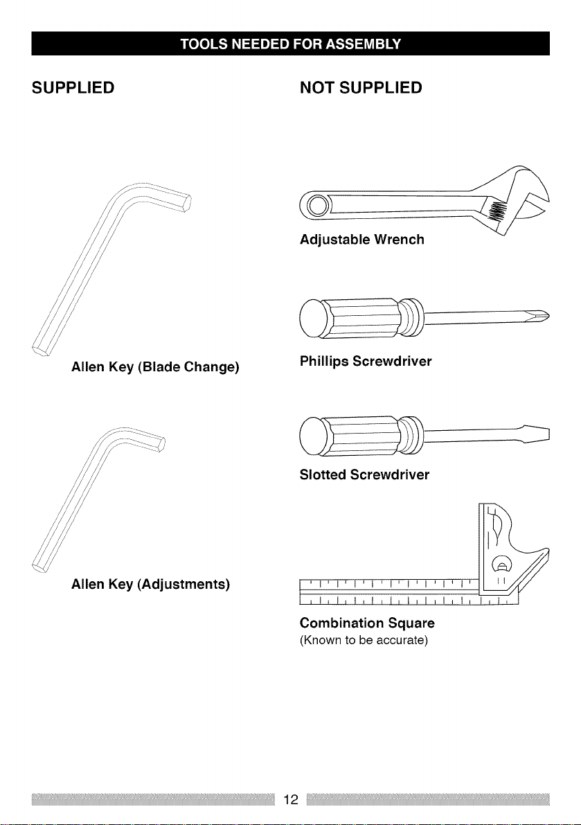
SUPPLIED NOT SUPPLIED
/
Adjustable Wrench
/
/
/
/
Allen Key (Blade Change)
/
/
/
/
/
Allen Key (Adjustments)
Phillips Screwdriver
Slotted Screwdriver
,I,1,t,t,I,I,1,1_1 _
Combination Square
(Known to be accurate)

UNPACKING YOUR MITER SAW
WARNING l
To avoid injury from unexpected starting
or electrical shock, do not plug the
power cord into a source of power during
unpacking and assembly.
The power cord must remain unplugged
when adjustments or maintenance to the
machine takes place.
1. Remove the miter saw from the carton.
IMPORTANT: Do not lift the miter saw by
the trigger switch handle. It may cause
misalignment.
2. Place the saw on a secure, stable work
surface.
3. Separate all the parts from the packing
material. Check each one with the
illustrations below to make certain that all
items are accounted for before discarding
any packing material.
l,_ WARNING i
If any part is missing or damaged do
not attempt to assemble the miter
saw, or plug in the power cord until
the missing or damaged part is
correctly replaced.
Call 1-800-469-4663 for missing or
damaged parts.
To avoid electric shock, use only
identical replacement parts when
servicing double insulated tools.
Call 1-800-469-4663 for
replacement parts.
7-1/4 inch Sliding Bevel Miter Saw
i
Hold Down Clamp
Dust Bag
13
Allen Keys

LINE DIAGRAM OF MITER SAW LEFT SIDE VIEW
/ / \\
2
4
/
,\
1- UPPER BLADE GUARD
2 - AUXILIARY BLADE GUARD
3 - CUTTING HEAD HANDLE
4 - BLADE (housed inside the bower blade guard)
5 - FENCE
6 - BEVEL LOCK HANDLE
7 - HOLD DOWN CLAMP
8 - MITER LOCK HANDLE
9 - DUST EXTRACTION PORT
14

LINE DIAGRAM OF MITER SAW RIGHT SIDE VIEW
4
6
1
2
1 - LOWER BLADE GUARD
2 - TABLE
3 - CUTTING HEAD LATCHING PIN
4 - ON/OFF TRIGGER SWITCH
5 - MOUNTING HOLE (there are 4 mounting holes in total, 2 at the back and 2 at the front)
6 - ARBOR LOCK BUTTON
15

AMPERAGE(AMPS)- Ameasureoftheflow
ofelectriccurrent.Higherratingsgenerally
meansthetootissuitedforheavieruse.
CUTTINGHEADLATCHINGPIN- Locks
themitersawintheloweredpositionfor
compactstorageandtransportation.
ARBOR-Theshaftonwhichthebladeis
mounted.
ARBORLOCK-Allowstheusertokeep
thebladefromrotatingwhiletightening
orlooseningthearborboltduringblade
replacementorremoval.
BASE- Supportsthetable,holds
accessoriesandallowsforworkbenchorleg
setmounting.
BEVELCUT-Ananglecutmadethrough
thefaceoftheworkpiece.
BEVELLOCKINGHANDLE- Locksthe
mitersawatadesiredbevelangle.
BEVELSCALE- Tomeasurethebevel
angleofthesawblade0°to45oleft.
TUNGSTENCARBIDETIPPED(TCT)
- Extremelyhardsteelpieceswithsharp
cuttingedgesfastenedtocuttingtoolssuch
assawblades.
DOUBLE-INSULATED- Aformofelectrical
protectionfeaturingtwoseparateinsulation
systemstohelpprotectagainstelectric
shock.
MITERSCALE- Indicatesthemiterangle
selected0°to45ototherighthandorleft
handside.
EXTENSIONCORD-Anelectricalcord
usedbetweenpowertoolsandoutletsto
extendthedistancebetweenthetwo.
Themoreamperageyourtoolusesand
thelongerthedistance,thelargerthewire
neededinyourextensioncord.
EYEPROTECTION- Gogglesorspectacles
intendedtoprotectyoueyes.Eyeprotection
shouldmeettherequirementsofANSIZ.87.1
(USA)orCSAZ94.3-M88(CANADA).
FACESHIELD-Animpactresistantshield
toprotectyourfacefromchips,sparks,small
debris.Shouldonlybeusedinconjunction
withadditionaleyeprotection.
COMPOUNDCUT- Acombinationofa
miterangleandabevelangle.
FENCE- Helpstokeeptheworkpiecefrom
movingduringcuttingoperations.
16

GUARD - Protective device that forms a
barrier between an hazardous object such as
a blade, wheel or cutter and the operator.
ON/OFF TRIGGER SWITCH - To start the
tool, squeeze the trigger. Release the trigger
to turn the miter saw OFF.
HOLD DOWN CLAMP - Secures the
workpiece during cutting operations.
OPERATORS MANUAL- Booklet
accompanying your power tool that describes
the hazards and safe operation procedures
and outlines basic tool operation, care and
maintenance.
KERF - The width of a saw cut, determined
by the thickness and set of the blade
KICKBACK - Sudden and unintended
movement of the tool or the workpiece.
It is typically caused by binding or pinching
of the workpiece.
MITER CUT - A miter is a type of joint where
the two parts to be joined are cut at an angle,
and typically the finished joint forms a 90
degree angle.
MOUNTING HOLES - Used to mount the
miter saw to a level stable work surface.
REVOLUTIONS PER MINUTE (RPM) -
The number of turns or rotations completed
by a spinning object in one minute.
SAW BLADE PATH - The area of the
workpiece or table top directly in line with
the travel of the blade or the part of the
workpiece which wilt be cut.
CUTTING HEAD HANDLE - Contains
the trigger switch. The blade is lowered by
pushing down on the handle. The saw wilt
return to its upright position when the handle
is released.
WARNING LABELS - For your own safety
read and understand any labels attached to
the machine.
17

WARNING
To avoid injury from unexpected starting
or electrical shock, do not plug the
power cord into a power source during
unpacking or assembly. The power cord
must remain unplugged whenever you are
working on the saw.
,A WARNING I
To avoid injury and/or damage to the saw,
transport or store the miter saw with the
Cutting Head locked in the down position.
Always ensure that the Cutting Head is
released from its locked position before
beginning cutting operations.
CUTTING HEAD
WARNING: To avoid serious injury, NEVER
perform the Cutting Head unlocking or
locking procedure unless the saw is OFF and
the blade has stopped turning.
Unlocking the Cutting Head (Fig. A)
a) With one hand grasp and gently press
down on the Cutting Head Handle.
b) With your other hand pull out the Latching
Pin from its socket and allow the head to rise
to its upper position.
NOTE: When the machine is not in use, lock
the Cutting Head in the down position with
the latching pin fully engaged in its socket.
Locking the Cutting Head in the Down
Position (Fig. B)
When transporting or storing the miter Saw,
lock the Cutting Head in the down position.
a) Lower the Cutting Head to its lowest
position.
b) Push the Latching Pin into the locking
socket
(Fig. a)
INSTALLING THE DUST COLLECTION BAG
Attach the dust collection bag at the dust
extraction port. (see KNOW YOUR SLIDING
MITER SAW page 14-15)
(Fig. A)
1. Slide the frame of the collection bag onto
the outlet of the extraction port, ensuring that
it is firmly connected.
2. To release the bag, slide the frame in the
opposite direction.
NOTE: To ensure optimal dust collection,
empty the dust bag when it becomes
approximately 2/3 full.
18

CAUTION l
Dispose of the contents of the dust
collection bag in an environmentally
responsible way. It may be neccesary to
wear a dust mask when emptying the dust
collection bag.
INSTALLING THE TABLE EXTENSION
ARMS
Extension arms are provided for the Right
Hand and Left Hand sides of the table. These
extension arms slide into holes machined at
either side of the machine base.
INSTALLING THE HOLD DOWN CLAMP
(Fig. C)
Two sockets (one on either side) are
incorporated into the rear of the machine
fence.
1. Fit the clamp into the retaining socket that
best suits the cutting application, ensuring
that it is fully pushed down.
2. Tighten the fence thumbscrew to lock the
pillar of the Hold Down Clamp into the fence
socket.
3. Put the workpiece to be cut onto the saw
bed.
4. Adjust the clamp using the thumbscrew
and hand-wheel so that it securely holds the
workpiece to the saw bed. Ensure that the
clamp does not interfere with the blade path.
NOTE: The extension arms should be
pushed 'fully home' into the machine base.
Correct installation will require approximately
3 inches of the extension arm to slide into the
machine base.
(Fig. D)
(Fig. C)
(Fig. D)
Fasten the arm(s) into the base by tightening
the appropriate screw in the base of the
fence socket(s)
19

INSTALLING OR REMOVING A BLADE
WARNING I
Only use blades which are specified for use
with this machine. Ensure that the maximum
speed of the blade is compatible with the
machine.
Only carry out this procedure with the
machine disconnected from the power
source.
NOTE: Wear protective gloves when
handling the blade during installation and
removal.
3. Rotate the lower blade guard up into the
upper blade guard. (Fig. F)
1. Ensure the cutting head is up.
2. Push the button at the front of the auxiliary
guard, and rotate the auxiliary guard to
expose the arbor bolt. (Fig. E)
(Fig. E)
(Fig. F)
4. Press the arbor lock button to lock the
arbor. (Fig. G)
20
(Fig. G)

5. Using the supplied Allen Key, release the
arbor bolt, remove washer, the blade collar,
and finally remove the blade. (Fig. H)
NOTE: The arbor screw is reverse threaded.
Turn to the right to loosen and tothe leftto tighten.
/
/
/
J
(Fig. J)
11. Ensure that all blade guards are correctly
positioned and fully functional.
NOTE: Spacers and spindle rings should not
be used with this machine and/or blade.
(Fig. H)
6. Install the new 7-1/4 in blade. Make sure that
the rotation arrow on the blade matches the
clockwise rotation arrow on the upper guard.
NOTE: The blade teeth should always point
downward at the front of the saw.
7. Install the blade, blade collar, washer and
arbor bolt, making sure that they are installed in
the correct order, as shown in (Fig. J) 1,2, 3, 4
8. Lock the arbor and tighten the arbor bolt
using moderate force, but do not overtighten.
9. Ensure that the Allen Key is removed and
the arbor lock has released by rotating the
blade by hand.
10. Return the auxiliary guard to its
service position.
1_, WARNING I
Ensure that the blade collars are clean and
correctly positioned on the arbor.
Lower the blade into the table and check
for any contact with the table or table insert.
Ifcontact occurs see CUTTING HEAD
TRAVEL (page 25)
MOUNTING THE MITER SAW
IA WARNING I
To reduce the risk of injury from unexpected
saw movement, place the saw in the
desired location either on a workbench or
other suitable machine stand. The base of
the saw has four mounting holes through
which suitable bolts can be placed to secure
the miter saw. Ifthe saw is to be used in
one location, permanently fasten it to the
workbench using appropriate fasteners (not
21

supplied). Use locking washers and nuts on
the underside of the workbench. (Fig. K)
washers, nuts, etc. to the underside of the
plywood mounting board to avoid an uneven
work surface.
3. Use 'C'- clamps to attach the mounting
board to the work surface. (Fig. L)
I I
I I
I I
I I
I I
I I
I I
I I
(Fig. K)
1. Tighten the miter and bevel locks.
See OPERATION section. ADJUSTMENT INSTRUCTIONS
2. To avoid injury from flying dust, position
the saw so that other people or bystanders
cannot stand too close (or behind) it.
3. Locate the saw on a firm, level surface
where there is plenty of room for handling
and properly supporting the workpiece.
4. Support the saw so the machine table is
level and the saw does not rock.
5. Bolt or clamp the saw securely to its
support stand or workbench.
For portable use:
1. Mount the saw on a % in. thick piece of
plywood using appropriate fasteners
(not supplied).
2. It may be necessary to countersink the
1,_ WARNING j
To avoid injury from electric shock or
from an accidental start, make sure the
switch is in the OFF position and the plug
is not connected a power source outlet.
NOTE: When checking angular
alignments the Cutting Head should be
lowered and locked in the down position
with the latching pin fully located in its
socket.
Refer to 'Locking the Cutting Head in the
Down Position' page 18.
0° Bevel Stop Adjustment
1. Ensure that the Cutting Head is upright
against its stop and the Bevel Pointer is
indicating 0° on the scale.
22

(Fig. M)
I'
(Fig. M)
2. Place a combination square on the miter
table with the rule against the table and the
heel of the square against the blade. (Fig. N)
3. If the blade is not 900 square with the miter
table, adjustment is required.
4. Loosen the Bevel Lock Handle and tilt the
Cutting Head to the left.
5. Loosen the Iocknut on the Bevel Angle
Adjustment Screw. (Fig. P)
(Fig. P)
6. Use an Allen Key to turn the screw in or
out to adjust the blade angle.
(Fig. N)
(Note for illustrative purposes only the Cutting
Head has been removed from this diagram).
7. Return the Cutting Head to its upright
position and recheck angular alignment
against the combination square.
8. Repeat steps 1 to 7 until correct angular
alignment is achieved.
9. Tighten the Bevel Angle Adjustment Screw
Iocknut securely.
23

0° Bevel Pointer Adjustment
NOTE: The operator must be satisfied that
the blade is set exactly perpendicular to the
table when in the upright position and against
its stop.
1. If the pointer is not in exact alignment
with the 0° mark on the protractor scale
adjustment is necessary.
2. Loosen the Bevel Pointer screw using a #2
Phillips screwdriver.
3. Adjust the Bevel Pointer so that it is in
alignment exactly with the 0° mark.
4. Retighten the screw.
450 Bevel Stop Adjustment
1. Loosen the Bevel Lock Handle and tilt the
Cutting Head completely to the left until it
rests against the 45ostop.
2. Use a combination square to see if the
blade is at 45oto the table.
3. If the saw blade is not in exact alignment
adjustment is necessary.
4. Return the Cutting Head to its upright
position.
5. Loosen the locknut on the 45o Bevel
Adjustment Screw.
6. Use an Allen Key to turn the Adjustment
Screw in or out as required. (Fig. Q)
(Fig. Q)
7. Tilt the Cutting Head to the 450 setting and
recheck for alignment with the combination
square.
8. Repeat steps 1 to 7 until the correct
angular alignment is achieved.
9. Tighten the Adjustment Screw Iocknut
securely once alignment is achieved.
1_, WARNING I
When all angular adjustments have been
successfully completed, the operation of
the lower safety guard must be checked
to ensure that it is working correctly.
The saw must not be used if the lower
safety guard is not operating correctly.
Fence Adjustment
The fence must be aligned at 90o (square)
to a correctly installed blade The rotary table
must be set at '0°' miter angle.
The Fence is fastened to the table with
four (4) socket head Allen screws that are
positioned two (2) at either side in elongated
slots.
24

1. Place a combination square on the table
with the rule against the Fence and the heel
against the Blade. (Fig. R)
(Fig. R)
(Note for illustrativepurposes only the Cutting
Head has been removed from this diagram)
2. If adjustment is necessary, loosen the four (4)
Fence adjustment screws using an Allen Key.
3. Re-position the Fence in its elongated
slots until alignment is achieved.
4. Securely tighten the socket head screws.
by loosening its fastening screw using a #2
Phillips screwdriver. Adjust as necsessary,
and then securely tighten the screw.
CUTTING HEAD TRAVEL
Cutting Head Downward Travel
Adjustment (Fig. S)
To prevent the blade from contacting any part
of the machine metal base the downward
travel of the Cutting Head can be adjusted.
Lower the Cutting Head and check for any
blade contact with the machine base.
If the downward travel of the Cutting Head
needs to be adjusted:
1. Loosen the Iocknut on the downward
travel stop screw.
2. Turn the adjusting screw out (counter-
clockwise) to decrease the downward travel
of the Cutting Head.
3. Turn the adjusting screw in (clockwise) to
increase the downward travel of the Cutting
Head.
4. Tighten the adjustment screw Iocknut
when satisfactory downward travel of the
Cutting Head is achieved.
(Fig. S)
Miter Angle Pointer Adjustment \
NOTE: There are dual miter angle scales
cast intothe front of the machine base.
A small pointer indicates the angle selected ....
Set the rotary table to 0° Miter ensuring that
the 0° Positive Stop is engaged. Check that
the Miter pointer is in exact alignment with
the 0° index mark.
If necessary the pointer can be repositioned
25
\

SAFETY INSTRUCTIONS FOR BASIC SAW
OPERATION
BEFORE USING THE MITER SAW
[,_ WARNING 1
To avoid mistakes that could cause
serious, permanent injury, do not plug the
machine in until the following steps are
com pleted:
Completely assemble and adjust the
saw, following the instructions.
(ASSEMBLY AND ADJUSTMENTS)
Learn the use and function of the ON/
OFF trigger switch, Lower Blade Guard
Release Lever, Upper and Lower Blade
Guards, Bevel Lock Handle and Cutting
Head latching pin.
Review and understand all safety
instructions and operating procedures in
this Operator's Manual.
Review the MAINTENANCE and
TROUBLESHOOTING GUIDE for your miter
saw.
To avoid injury or possible death from
electrical shock:
Make sure that your fingers do not touch
the plugs metal prongs when plugging
in or unplugging your miter saw.
(ELECTRICAL REQUIREMENTS AND
SAFETY)
BEFORE EACH USE INSPECT YOUR SAW
Disconnect the miter saw.
To avoid injury from accidental starting,
unplug the saw before any adjustments,
including set-up and blade changes.
Compare the direction of rotation
arrow on the guard to the direction
arrow on the blade.
The blade teeth should always point
downwards at the front of the saw.
Tighten the arbor bolt.
Check for damaged parts. Check for:
Cracks in the blade, and for broken,
chipped or missing blade teeth.
Alignment of moving parts
Damaged power cords
Binding of moving parts
Mounting holes
Operation of the Lower Blade Guard:
Push the Cutting Head all the way
down, and then let it rise to until it
stops. The Lower Blade Guard should
fully close enclosing the blade. Follow
instructions inTROUBLESHOOTING
GUIDE for adjustment if necessary.
Any other conditions which may affect
the way your miter saw works.
Keep all guards in place, in working
order and proper adjustment. If any
part of your miter saw is missing, bent,
damaged or broken in any way, or any
electrical parts do not work, turn the saw
OFF and unplug it.
Replace bent, damaged, missing or
defective parts before using the saw
again.
Maintain tools with care. Keep the
miter saw clean for best and safest
performance. Follow instructions for
lubricating. Do not put lubricants on the
blade while it is spinning.
Remove any adjusting tools from the
saw before turning it ON.
To avoid injury from jams, slips or
thrown pieces, use only recommended
accessories.
Check the dust bag before you start work.
Empty the bag ifitis more that half-fulL
26

AVAILABLE ACCESSORIES
Consult the ACCESSORIES and
ATTACHMENTS section of this Operator's
Manual for the available accessories.
Follow the instructions that come with the
accessory. The use of improper accessories
may cause risk of injury to persons.
Choose the correct 7-1/4 in. diameter
blade for the material and the type of
cutting you plan to do. Do not use thin kerf
blades.
Make sure the blade is sharp,
undamaged and properly installed. With
the saw unplugged push the Cutting
Head all the way down. Manually spin
the blade and check for clearance. Tilt
the Cutting Head to a 450 bevel angle
and repeat the test.
Make sure that blade and arbor collars
are clean.
Make sure all clamps and locking
screws are tight and that there is no
excessive play in any parts.
KEEP YOUR WORK AREA CLEAN
WARNING 1
Cluttered areas and benches invite
accidents.To avoid burns or other fire
damage, never use the miter saw near
flammable liquids, vapors or gases.
Plan ahead to protect your eyes, hands,
face and ears.
Know your miter saw. Read and
understand this Operator's Manual and
the labels affixed to the tool. Learn its
application and limitations as well as the
specific potential hazards peculiar to
this toot. To avoid injury from accidental
contact with moving parts, do not do lay
out, assembly or setup work on the miter
saw while any parts are moving.
To avoid accidental starting, make sure
that the trigger switch is in the OFF
position before plugging the miter saw
into a power supply.
PLAN YOUR WORK
Use the right tool. Do not force a tool
or attachment to do a job it was not
designed to do. Use a different tool for
any workpiece that cannot be held in a
solidly braced, fixed position.
1_, CAUTION j
This machine is not designed for cutting
masonry products or products containing
asbestos type materials. Use this miter
saw to cut wood, and wooden based
products. Other materials may shatter,
bind the blade, or create other hazards.
Inspect the workpieee for any prohibited
materials before you begin cutting.
Remove any nails, screws or other such
foreign objects before you start cutting.
DRESS FOR SAFETY
O Any power tool can throw
eye damage. Everyday eyeglasseshave only
impact resistantlenses and are notsafety
glasses.Glasses or goggles not in compliance
withANSI Z87.1 could seriously injure you
when they break.
foreign objects into the eyes.
This can result in permanent
27
 Loading...