

Page 1
FR Manuel d'utUisation, pp. 23-44 I 2SEx_sERIES
EN Operator's manual, pp, 2-22 .125B Q
ES Manual de instrucciones, pp. 45-66
EN FR ES
Page 2
CONTENTS
Contents
Introduction ................... 2
Key to symbols .................. 3
Safety instructions ............... 4
Description ..................... 6
Fuel handling .................... 11
Starting and stopping ............ 12
Using the blower ................. 13
Maintenance .................... 18
Technical data ................... 19
Maintenance, replacement, or repair of the
emission control devices and system may
be performed by any nonroad engine re-
pair establishment or individual
WARNING
Theengine exhaust from this product
containschemicalsknown to theState
ofCaliforniatocausecancer,birth
defectsorotherreproductiveharm.
Note the following before
starting:
Husqvama AB has a policy of continuous
product development and therefore
reserves the right to modify the design and
appearance of products without prior
noede. Long-term exposure to noise can
result in permanent hearing impairment.
Always use approved hearing protection.
This operator's manual describes in detaJ+
how to use and service the blower and
how to carry out regular maintenance. It
also descdbes which measures should be
taken to achieve maximum safety while
operating the blower, how the safety de-
vices work and how they should be ser-
viced.
Note[ The section of the manual that deals
with safety, must be read and understood
by all persons who come in contact with
the blower.
This operator's manual has been wdnen
for those who need guidance when it
comes to fault tracing, thorough servicing
and carrying out corrective maintenance of
the blower.
There are warning symbols on the blower.
Should any of the warning symbols on the
blower become disfigured or worn, new ones
should be ordered and fitted to the blower as
soon as possible. Note that some of the
warning symbols may be molded in certdln
components of the blower.
The blower is used for blowing away leaves
and other debris on the ground. When op-
erating the blower, the operator must stand
with both feet firmly on the ground.
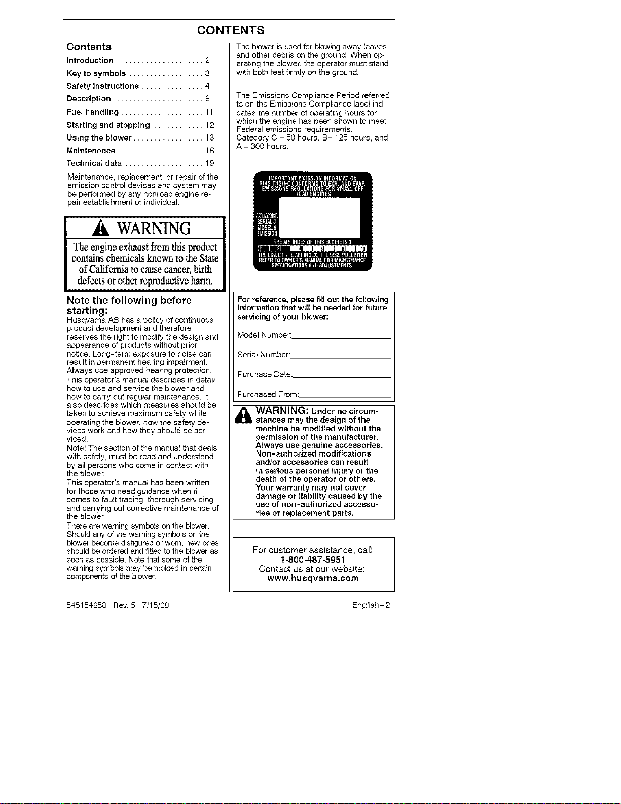
The Emissions Compliance Period referred
to on the Emissions Compliance label indi-
cates the number of operating hours for
which the engine has been shown to meet
Federal emissions requirements.
Category C 50 hours, B 125 hours, and
A 300 hours.
For reference, please fill out the following
information that will be needed for future
servicing of your blower:
Model Number:
Serial Number:
Purchase Date:
Purchased From:
WARNING: Under no circum-
stances may the design of the
machine be modified without the
permission of the manufacturer.
Always use genuine accessories.
Non-authorized modifications
and/or accessories can result
in serious personal injury or the
death of the operator or others.
Your warranty may not cover
damage or liabiIRy caused by the
use of non-authorized accesso-
ries or replacement parts.
For customer assistance, calI:
1-800-487-5951
Contact us at our website:
www.husqvarna.com
English-2545154658 Rev. 5 7/15/08
Page 3
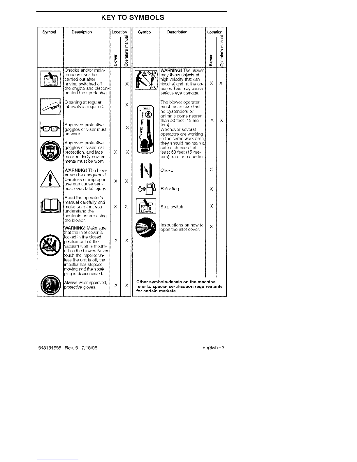
KEY TO SYMBOLS
o_ _ el Descrtpt{on LocationSymbol Descrlptien Locatio_ ;yml _ _"_.
lllmaythr°wohi tsatI I
II_ f II high veJocity that can { I
carried out after
ricochet and hit the op- × ×
_ eratoL This may causethe engine and discon-
nected tile spark plug sedous eye damage
_ Cleaning at regulal X _ The btower oparatol
i. must make sure that
intervals is required _ - no bystanders or
( animals oome nealer
I_ I i {than50feet(15n_e- X X
Applovedplotecfive II !tels) I I
goggles el visor must X Whenever sevelal
be WOrn. ope[ators are working
_'! ill the same work area,
{_ Apploved plotective they should maiatahl a
safe distance of atgoggles el visor, ear
protection, and face X X ' _ least 50 feet (15 me-
_F'J Imask in dusty environ- I I II I _ I tels) from one another
ments must be worn
WARNING! The blow- Choke X
er can he dangerous!
Care_easSc°_hs_P_°f_er X X
x
Read the operator's
i_ manual carefully and [
make sure that you X X Stop switch X
understand thecovel "._ _ _lf_t
contents befole using
the blowel
that the inter is _._
lockedintheclosed
position or that the X X
vaouum tub@ is mount-
ed on the bloweE Never
touch the impaIler un-
less the unit is off, the /
impaller has stopped
!
moving and the spark
plug is disoonneated
I Always wear approved, Other symbols/decals on the machine
protective gloves X X refer to special certification requirements
for certain markets.
545154658 Rev. 5 7/15/08 English-3
Page 4
SAFETY INSTRUCTIONS
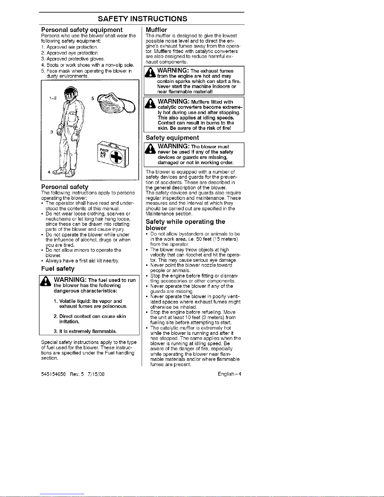
Personal safety equipment
Persons who use the blower shall wear the
following safety equipment:
1. Approved ear protection.
2. Approved eye protection
3. Approved protective gloves.
4. Boots or work shoes with a non-slip sole.
5. Face mask when operating the blower in
dusty environments.
Personal safety
The following instructions apply to persons
operating the blower:
• The operator shall have read and under-
stood the contents of this manual.
• Do not wear loose clothing, scarves or
neckchains or let long hair hang loose,
since these can be drawn into rotating
parts of the blower and cause injury.
• Do not operate the blower while under
the influence of alcohol, drugs or when
you are tired.
• Do not allow minors to operate the
blower.
• Always have a first aid kit nearby
Fuel safety
_ WARNING: The fuel used to run
the blower has the following
dangerous characteristics:
1. Volatile liquid: its vapor and
exhaust fumes are poisonous.
2, Direct contact can cause skin
irritation.
3. It is extremely flammable.
Special safety instructions apply to the type
of fuel used for the blower. These instruc-
tions are specified under the Fuet handling
section.
545154658 Rev. 5 7/15/08
Muffler
The muffler is designed to give the lowest
possible noise level and to direct the en-
gine's exhaust fumes away from the opera-
tor. Mufflers fitted with catalytic converters
are also designed to reduce harmful ex-
haust components.
WARNING: The exhaust fumes
from the engine are hot and may
contain sparks which can start a fire.
Never start the machine indoors or
near flammable material!
WARNING: Mufflers fitted with
catalytic converters become extreme-
ly hot during use and after stopping.
This also applies at idling speeds.
Contact can result in burns to the
skin. Be aware of the risk of fire!
Safety equipment
WARNING: The blower must
never be used if any of the safety
devices or guards are missing,
damaged or not in working order.
The blower is equipped with a number of
safety devices and guards for the preven-
tion of accidents. These are described in
the general description of the b_ower.
The safety devices and guards also require
regular inspection and maintenance. These
measures and the interval at which they
should be carried out are specified in the
Maintenance section.
Safety while operating the
blower
• Do not allow bystanders or animals to be
in the work area, i.e 50 feet (15 meters)
from the operator.
• The blower may throw objects at high
velocity that can ricochet and hit the opera-
tor. This may cause serious eye damage.
• Never point the blower nozzle toward
people or animals.
• Stop the engine before fitting or disman-
tling accessories or other components.
• Never operate the blower if any of the
guards are missing.
• Never operate the blower in poorly venti-
lated spaces where exhaust fumes might
otherwise be inhaled.
• Stop the engine before refueling. Move
the unit at least 10 feet (3 meters) from
fueling site before attempting to start.
• The catalytic muffler is extremely hot
while the blower is running and after it
has stopped. The same applies when the
blower is running at idling speed. Be
aware of the danger of fire, especially
while operating the blower near flam-
mable materials and/or where flammable
fumes are present
English-4
Page 5
SAFETY INSTRUCTIONS
• Be careful, particularly if _ett hand opera-
tion is applied. Avoid any direct body con-
tact with inlet cover area. Keep jewelry,
loose clothing, or clothing with loosely
hanging straps, ties, tassels, etc., away
from inlet cover area.
• Do not operate the blower while standing
on a ladder or a stand.
Other safety measures
Operate the blower only at reasonable
hours, i.e. not early in the morning or late
at night when people might be disturbed
Comply with times listed in local ordi-
nances. Usual recommendations are 9:00
a.m to 5:00 p.m., Monday through Satur-
day.
• Operate the blower at the lowest possible
throttle setting to do the job.
• Check the condition of the blower before
operation, especially the muffler, air intake
and air filter.
• Use a rake or a broom to loosen ground
debris before blowing
• Under dusty conditions, slightly spray the
work area with a hose.
• Conserve water by using blowers instead
of hoses for many lawn and garden
applications, including areas such as roof
gutters, screens, patios and gardens etc.
• Watch out for children, pets, open windows
or vehicles, and blow debris safely away.
• Use the full nozzle extension so the air
stream can work close to the ground.
• After using the blower, clean up and
dispose of debris in trash receptacles.
545154658 Rev. 5 7/15/08 English-5
Page 6
DESCRIPTION
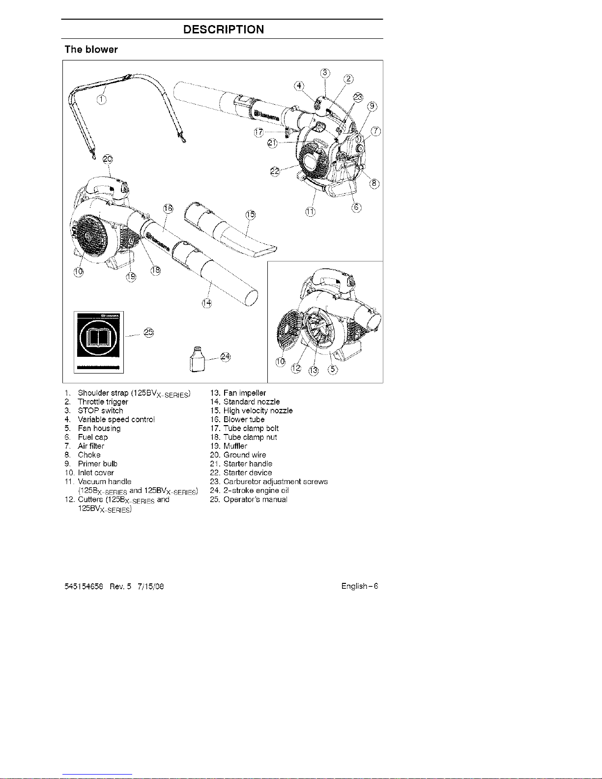
The blower
1. Shoulder strap (125BV x SERIES) 13. Fan impeller
2. Throttle trigger 14. Standard nozzle
3. STOPswitch 15. High ve{ocity nozzle
4. Variab{espeed control 16. BIowertube
5. Fan housing 17. Tube clamp bolt
6. Fuel cap 18. Tube clamp nut
7. Airfilter 19. Muffler
8. Choke 20. Ground wire
9. Primer bulb 21. Starter handle
10. Inlet cover 22. Starter device
11 Vacuum handle 23. Carburetor adjustment screws
(125Bx SERIESand 125BV x SERES) 24. 2-stroke engine oil
12. Cutters (125B x SEREESand 25. Operator's manual
125BVx SERIES)
54-5154658 Rev. 5 7/15/08 English-8
Page 7
DESCRIPTION
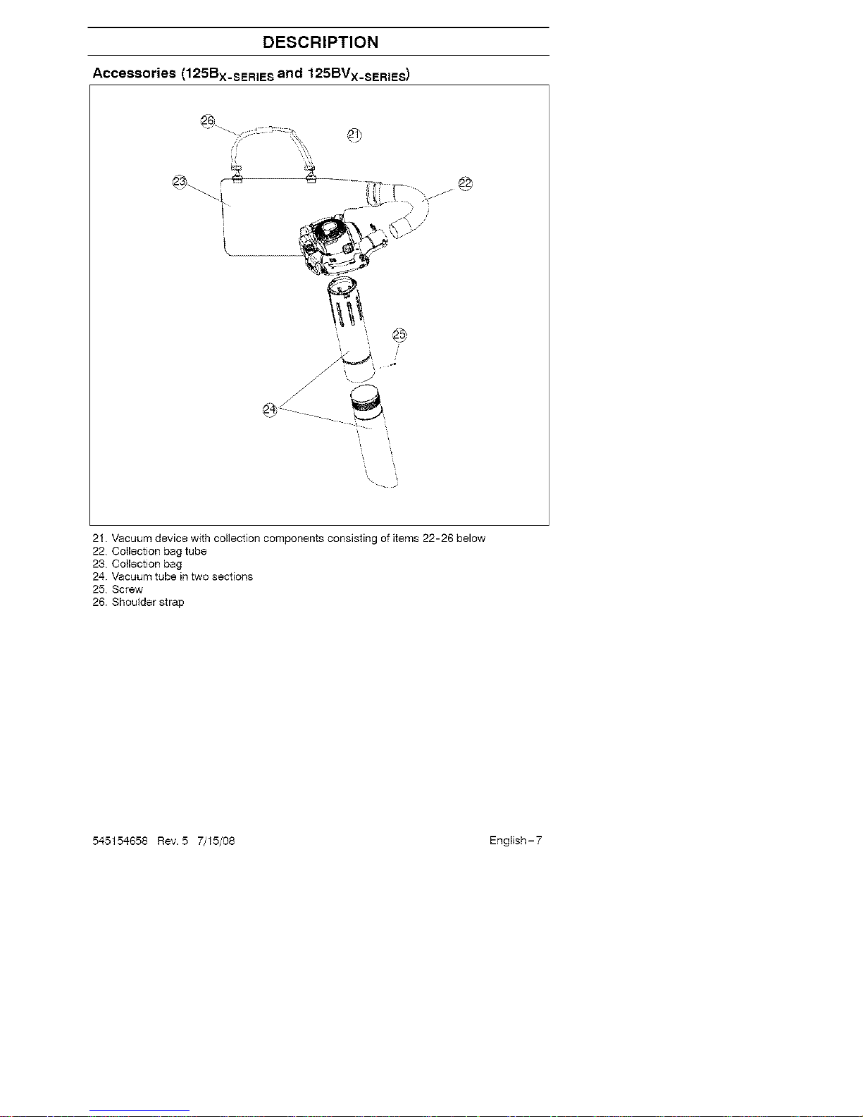
Accessories (125Bx_sERIESand 125BVx_sERIES)
©
. @
21. Vacuum device with collection components consisting of items 22-26 below
22. Collection bag tube
23. Collection bag
24. Vacuum tube in two sections
25. Screw
26. Shoulder strap
545154658 Rev. 5 7/15/08 English-7
Page 8

DESCRIPTION
Safety equipment
The following equipment on the blower is
designed for protecting personnel and
materials. These components should
receive special attention whenever you
operate, inspect and service the blower.
Stop switch
• The stop switch (A) is used to stop tile
engine.
j_ A
.J
/
Muffler
• The muffler is designed to give the low-
est possible noise level and to direct the
engine's exhaust fumes away from the
operator. Mufflers fitted with catalytic
converters are also designed to reduce
harmful exhaust components.
• The engine exhaust fumes are hot and
can contain sparks, which may cause
fire if they come in contact with dry or
flammable material
• Some blower models, especially those
sold in countries where the climate is
dry, are equipped with a spark arresting
screen (B). This screen must be cleaned
or replaced at specific intervals See the
Maintenance section
B
WARNING: The muffler is ex-
tremely hot while the engine is run-
ning and after it has stopped. DO
NOT TOUCH THE MUFFLER IF IT IS
HOT! This can cause severe burns.
545154658 Rev. 5 7/15/08
Other equipment
Throttle trigger
• The speed and the output of the engine
are regulated by the throttle trigger (C).
/
C
Variable speed control
• The variable speed control (D) is de-
signed to allow setting engine speed as
necessary during blower use only.
/
• To avoid causing damage to the unit, DO
NOT attempt to use the variable speed
control during starting or during vacuum
use.
Fan housing
• The blower fan housing (E) and the fan
impeller (F) provide high performance air
discharge.
+
F /
E
English-8
Page 9

DESCRIPTION
Ground wire
• The ground wire (G) reduces static
beNd-up during operation indry condb
tions.
!
Inlet cover
• An inlet cover (H) is located on the side
of the fan housing• Opening this cover
allows access for cleaning and inspect-
ing the impe,er (125Bx SERIES and
125BVx SERES only). If the vacuum tube
is used. it must be fitted to the opening in
the inlet cover• To open the inlet cover.
use a tool to lift the edge of the cover
opposite the hinge (indicated by arrow
on inlet cover).
H
j•
WARNING: Never start the blower
if the inlet cover is not closed, is
damaged or cannot be closed
(except if the vacuum tube is fitted).
Cutter8
(125BX_SERIES and 125BVx_sERIES)
• Two cutters (J) are fastened to the impeF
lee The cutters are there to mulch leaves
and other debris that have been vacuumed
before they enter the collection bag.
Blower tube and nozzle
NOTE: The tube clamp bolt and nut must
be insta,ed prior to initial use (see the gen-
eral description of the blower on page 6)
• The blower tube (K) has a begged slot
mounting system to the unit To install or
remove the bbwer tube (or co,ecf_3n bag
tube for the 125BVx SERIES).the tube
clamp bolt must be removed• Align slot in
the bbwer air outlet with the raised rib on
the tube and insert tube until the holes in
the tube and housing align. Re-insert the
tube clamp bolt and tk:jhten.
• The nozzles (L) have a bayonet mount
for connection to the blower tube• Air is
channeled through the blower tube to the
nozzles, where the air discharge velocity
increases and the air stream discharge
pattern is formed to prov{de best perfor-
mance. The length of the blower tube
can be adjusted by twisting the nozzle to
the left to disengage the bayonet mount
and sliding the nozzle to the appropriate
position. Twist the nozzle to the right until
a click is fed to resecure the nozzle
K
Starter device and 8tarter handle
• The starter device (M) is located on the
side of the engine shrouding and en-
gages the crankshaft only when the
starter handle (N) is pulled.
_%... jrt" '2
Fuel cap
• The fuel cap (O) is located at the rear of
the engine shrouding on the fuel tank
and has a seal to prevent fuel from leak-
ing out.
j' L%
Air filter
• The air filter (P) consists of a fiber filter
medium in a resilient frame. The air filter
should be cleaned at specific intervals
(see Maintenance section). Otherwise,
the blower will consume too much fuel.
the performance win be reduced and an
oily deposit may form on the spark plug
electrodes•
545154658 Rev. 5 7/15/08 English-g
Page 10

DESCRIPTION
Choke
• The choke (Q) is located below the air
filter cover and should be used every
time the engine is cold-started
'S%,-, j_ '2
Adjusting the carburetor
NOT FOR ALL MODELS
• There are three adjusting screws (R)for
adiusting the carburetor:
• Low speed jet
• High speed jet
• Adjustment screw for idling
• Adjusting the carburetor involves adapt-
ingthe engine to local operating condi-
tions, e.g. climate, altitude, gesoline and
type of two-stroke engine oil used For
details about carburetor adjustment, see
the Maintenence section.
545154658 Rev. 5 7/15/08 English-10
Page 11

FUELHANDLING
Fuel mixture
CAUTION! The machine is equipped with
a two-stroke engine and must always be
run using a mixture of gasoline and two-
stroke engine oil. It is important to accu-
rately measure the amount of oil to be
mixed to ensure that the correct mixture is
obtained. When mixing sinai+ amounts of
fuel, even smelt inaccuracies can drasticaF
ty effect the ratio of the mixture
&WARNING: Always ensure
there is adequate ventilation when
handling fuel.
Gasoline
CAUTION! Always use high quality
unleaded gasoline
• This engine is certified to operate on
unleaded gasoline.
• The _owest recommended octane rating
is 87. If you run the engine on lower oc-
tane rating than 87, "knock{ng" can oc-
cur. This leads to an increased engine
temperature, which can resutt in a serb
ous engine breakdown.
• When working at continuous high rays a
higher octane rating is recommended.
Two-stroke oil
• For great resutts and performance use
HUSQVARNA two-stroke oil, which is
special+y formutated for our two-stroke
engines. Mixture 1:50 (2%).
• To maximize the life of your blower, you
may choose to use a high quality syn-
thetic oil formulated for two-stroke
engines. Mixture 1:50 (2%).
• Never use two-stroke oi+ intended for
water-cooled outboard engines,
sometimes referred to as outboard oil.
• Never use oit intended for four-stroke
engines.
Two-stroke oil
Gasoline 2% (1:50)
U.S. gallon U.S. fl. oz.
1 2 1/2
2 1/2 6 1/2
5 12 7/8
Mixing
• Always mix the gasoline and oit in a
clean container intended for fuel.
• Always start by filling haft the amount of
the gasoline to be used. Then add the
entire amount of oil. Mix (shake) the fuel
mixture. Add the remaining amount of
gasoline.
• Mix (shake) the fuei mixture thoroughly
before fi+ling the machine's fuet tank.
• Do not mix more than one month's sup-
ply of fuel at a time.
• if the machine is not used for some time,
the fuel tank should be emptied and
cleaned.
WARNING: The catalytic con-
verter muffler gets very hot during
and after use. This also applies
during idling. Be aware of the fire
hazard, especially when working
near flammable substances and/or
vapors.
Fueling
WARNING: Taking the following
precautions, will lessen the risk of
fire:
Do not smoke or place hot objects
near fuel.
Always shut oft the engine before
refueling.
Always stop the engine and let it
cool for a few minutes before
refueling.
When refueling, open the fuel cap
slowly so that any excess pressure
is released gently.
Tighten the fuel cap carefully after
refueling.
Always move the machine away
from the refueling area before
starting.
545154658 Rev. 5 7/15/08 English - 11
Page 12

STARTING AND STOPPING
• Clean the area around the fue{ cap.
Contamination {n the tank can cause
operating problems.
• Ensure that the fuel is well mixed by shak-
ing the container before filling the tank.
Starting and stopping
WARNING: Never start the blower
if the inlet cover is not closed, is
damaged or cannot be closed
(except if the vacuum tube is fitted).
Cold engine
Primer bulb: Press the primer bulb 10
times until fuel begins to fill the bulb. The
primer bulb need not be completely filled.
Choke: Move the blue engine choke ]ever
over to the FULL CHOKE (closed) besitJon.
Starting: Hold the body of the machine on
the ground using your ]eft hand
CAUTION! Not with your foot0.
Firmly grip the starter rope handle with
your right hand. DO NOT squeeze
throttle trigger, Slowly pull out the cord
until you feel some resistance (the starter
paw_s grip); then quicMy and powerfully
)u_lthe cord.
_1 WARNING: Never wrap the starter ]
cord around your hand. J
Pull starter handle unti_ engine attempts to
run, but no more than 3 pulis. Move choke
to 'J, position and pull the cord until the en-
gine starts and runs. Allow the engine to
warm up for approximately 10 seconds:
then, move the choke to the OFF CHOKE
(opened) position.
NOTE: If engine dies, return blue engine
choke lever to the closed position and
repeat starting steps.
CAUTION! Do not pull the starter cord all
the way out and do not let go of the starter
handle when the cord is fully extended
This can damage the machine.
Warm engine
With a warm engine, squeeze and hold the
throttle trigger. Move choke to 1/zposition.
Pull starter rope sharply while squeezing
throttle trigger until engine runs. Move the
choke to the OFF CHOKE (opened)
3osition.
I
Stopping
To stop the engine, push and release the
engine STOP switch (S). The switch will
automatically return to the ON position.
Wait 7 seconds before attempting to restart
unit to allow switch to reset.
!
545154658 Rev. 5 7/15/08 English-12
Page 13

USING THE BLOWER
To blow away debris on the
ground
Fitting the blower tube and nozzle
on the blower
&WARNING: When fitting the blow-
er tube and nozzle, the engine must
be switched off.
The blower tube (T) has a begged slot
mounting system to the unit. To install or
remove the blower tube (or collection bag
tube for 125BV X SERIES), the tube clamp
bolt must be removed Align slot in the
blower air oubet with the raised rib on the
tube and insert tube until the holes in the
tube and housing align Re-insert the tube
clamp bolt and tighten•
!,½ :
°i
T
The nozzles (U) have a bayonet mount for
connection to the blower tube• Air is chan-
neled through the blower tube to the
nozzles, where the air discharge velocity
increases and the air stream discharge pat-
tern is formed to provide best performance.
The length of the blower tube can be ad-
justed by twisting the nozzle to the left to
disengage the bayonet mount and sliding
the nozzle to the appropriate position.
Twist the nozzle to the right until a click is
fe{t to re-secure the nozzle
Blowing
Before you begin blowing, put on tile re-
quired safety equipment•
WARNING: When working with
the blower, wear the required per-
sonal safety equipment:
1. Hearing protection.
2. Eye protection.
g. Protective gloves.
4. Face mask in dusty environments.
125BVx SERIEScan be used with a shoul-
der strap for extra comfort. The strap
should be worn over the sbeulder as
shown
&
WARNING: Never point the blower
nozzle at people or animals. The
high-velocity air stream can contain
particles that may cause serious
injury, especially if the blower has
previously been used for vacuuming.
Be careful, particularly if left hand
operation is applied. Avoid any di-
rect body contact with inlet cover
area. Keep jewelry, loose clothing,
or clothing with loosely hanging
straps, ties, tassels, etc., away from
inlet cover area.
54-5154658 Rev. 5 7/15/08 English-13
Page 14

USING THE BLOWER
&WARNING: Never start the blower
if the inlet cover is not closed, is
damaged or cannot be closed
(except if the vacuum tube is fitted).
&WARNING: Do not operate the
blower while standing on a ladder or
a stand.
Start the bbwer as described in the Starting
and Stopping section. Work according to the
following instructions:
1. Never blow air toward fixed objects such
as wails, large rocks, automobiles and
fences.
2. When working inside corners, blow from
the corner and inward toward the center of
the work area. Otherwise, debris can fly
up in your face and cause eye injury.
3. Never point the blower nozzle at delicate
plants.
Standard nozzle
The standard nozzle (V) is included with
the 125B, 125Bx SERESand 125BVx SE
RIES.When greater accuracy and high air
stream concentration is desired, use the
standard nozzle.
V
High-velocity nozzle
The high-velocity nozzle (W) is an acces-
sory of the blower (included with the
125Bx SERIES and 125BV x SERIES)-
When a wider air stream and greater air
velocity is desired, use the high-velocity
nozzle.
To vacuum debris from the
ground (125Bx.sERIES and
125BVx_sERIES )
Fitting the collection bag with the
various vacuum tube8
The vacuuming device is an accessory (in-
cluded with the 125BV x SERIES).
_ WARNING: When the
fitting
tubes to the blower, the engine
must be switched off.
1. Open the collection bag. Insert the
collection bag tube from inside the bag to
fit in the vacuum inlet opening of the bag
as shown. Ensure elastic is seated in
groove. Close the zipper on the bag.
2. Remove the blower tube and install the
collection bag tube. Install and tighten
tube clamp bolt. Attach the carrying strap
to the collection bag loops.
3. Align arrows on lower vacuum tube and
upper vacuum tube. Push bwer vacuum
tube into upper vacuum tube until the lower
tube is securely seated in the upper tube
(about 3 inches/7 cm). Permanently as-
semble the two tubes together with the
supplied screw.
0
rk Open the cover on the s_de of the blower
by using a screwdriver to pry up under the
edge of the cover on the side opposite the
hinge (indicated by arrow on inlet cover).
5. Press the vacuum tubes in the large
opening at the underside of the blower
and align the tabs with the slots in the
tube. Turn it until the bayonet mount
locks (_ock symbols _, align).
545154658 Rev. 5 7/15/08 English-14
Page 15

USING THE BLOWER
Vacuuming
Before vacuuming, put on tile required
safety equipment.
_1 WARNING: When working with
the blower, wear the required per-
sonal safety equipment:
1. Hearing protection.
2. Eye protection.
3. Protective gloves.
4. Face mask in dusty environments.
When operating the blower, the collection
bag must be supported by the shoulder
strap. The strap should be worn over the
shoulder as shown.
_1 WARNING: check that
Always
tbe collection bag is intact and the
zipper is closed before starting tbe
blower. Never use a damaged bag.
There is risk of injury due to flying
debris. Be careful, particularly if left
band operation is applied. Avoid any
direct body contact with the ex-
haust outlet area.
_1 WARNING: Never start the blower ]
if the inlet cover is not closed, is
damaged or cannot be closed
(except if the vacuum tube is fitted),
WARNING: Do not the
operate
blower while standing on a ladderor
a stand.
Start the blower as described in the Starting
and Stopping section. Work according to the
following instructions:
1. Do not vacuum large solid objects that
can damage the fan, such as wood, cans
(tins) or lengths of string or ribbon.
2. Do not let the vacuum tube strike the
ground.
3. The collection bag can be emptied by first
stopping the unit and then opening the zip-
per on the side.
54-5154658 Rev. 5 7/15/08 English-15
Page 16

MAINTENANCE
Maintenance Safety
The owner is responsible for the perfor-
mance of all required maintenance as
defined in the operator's manual.
Disconnect the spark plug before perform-
ing maintenance, except carburetor adjust-
ments.
&WARNING: tmproper mainte-
nance could result in serious engine
damage or in serious injury.
Carburetor
Your Husqvama product has been designed
and manufactured to specifications that re-
duce harmful emissions. After the engine
has used 8-10 tanks of fuel, the engine witt
be run-in. To ensure that it continues to run
at peak performance and to minimize harm-
ful exhaust emissions after the run-in peri-
od, ask your servicing dealer to adjust your
carburetor.
Function
• The carburetor governs the engine's
speed vie the throttle control Air and fuel
are mixed in the carburetor.
• The T-screw (BB) regulates the throttle
setting at idle speed. If the T-screw is
turned clockwise this gives a higher idle
speed; turning it counterclockwise gives a
lower idle speed.
Basic setting
• The basic carburetor settings are ad-
justed during testing at the factory. Fine
adjustment should be carried out by a
skirled technician.
Recommended idle speed:
See "Technical data" section.
Recommended max. speed:
See "Technical data" section
Fine adjustment of the idle speed-T
Adjust the idlespeed using the idle adjust-
ment T-screw if itis necessary to readjust.
The idlespeed iscorrectly adjusted when
the engine wilt run smoothly inevery posi-
tion.
BB
Muffler
Some mufflers are fitted with catalytic con-
verters. See the Technical data section to
find out if your machine is equipped with a
catalytic converter.
The muffler is designed to dampen the
noise level and to direct the exhaust fumes
away from the use£ The exhaust fumes
are hot and can contain sparks, which can
result in fire if the exhaust fumes are
directed towards a dry and flammable
material.
Some mufflers are equipped with a special
spark arresting screen (CC). If your ma-
chine is fitted with this type of screen, it
should be cieaned regulady. To access the
screen, remove the outlet cover on the
front of the muffler. Use a wire brush to
clean the screen On mufflers without a
catalytic converter the screen should be
cieaned weekly, or replaced if necessary.
On mufflers fitted with a catalytic converter
the screen should be checked and cleaned
monthly. If the screen is damaged it
should be replaced. If the screen is fre-
quently blocked, this can be a sign that the
function of the catalytic converter is im-
paired Contact your dealer to inspect the
muffler. A blocked screen wiil cause the
engine to overheat resulting in damage to
the cyiinder and piston
CAUTION! Never use a machine that has
a faulty or loose muffler. Ensure the muffler
bolts are tight.
545154658 Rev. 5 7/15/08 English-16
Page 17

MAINTENANCE
/CC
_1 WARNING: Mufflersfitted with
catalytic converters get very hot
during use and remain so for some
time after stopping. This also ap-
plies at idle speed. Contact can re-
sult in burns to the skin. Remember
the risk of fire!
WARNING: Bear in mind that:
Engine exhaust fumes contain car-
bon monoxide, which can cause
carbon monoxide poisoning. For
this reason you should not start or
run the machine indoors, or any-
where that is poorly ventilated.
The exhaust fumes from the engine
are hot and may contain sparks
which can start a fire. Never start
the machine indoors or near flam-
mable material!
_1_ WARNING: The inside of the
muffler contain chemicals that may
be carcinogenic. Avoid contact with
these elements in the event of a
damaged muffler.
Cooling system
The engine is equipped with a coefing
system for maintaining the right operating
temperature•
The cooling system consists of the follow-
ing components:
1.Air intake on the starter device (DD).
2. Fan blades on the flywheel (EE).
3. Cooling fins on the cylinder (FF).
4. Cylinder cowling (guides cooling a{r f_ow
aga{nst cylinder surfaces).
Ctean the coefing system by brushing once
a week, or more often, if necessary.
A dirty or b_ocked coefing system will
cause the b_ower to overheat and this will
damage the cytinder and piston
EE
Air filter
The air filter (GG) must be regulady cleaned
to remove dust and dirt in order to avoid:
• Carburetor mallunctions
• Starting problems
• Loss of engine power
• Unnecessary wear to engine parts
• Excessivefuef consumption
• Elevated content of harmful exhaust
fumes•
Clean the filter every 25 hours, or more
regularly if conditions are exceptionally
dusty.
Cleaning the air filter
Remove the air fiEter cover (HH) and take out
the filter. Wash it clean in warm, soapy water•
Rinse thoroughly. Ensure that the _ter is dry
before reinstalling it
An air filter that has been in use for a long
time cannot be cleaned completely. The
filter must therefore be replaced with a new
one at regular intervals.
CAUTION! A damaged air filter must
always be replaced.
545154658 Rev. 5 7/15/08 English-17
Page 18

MAINTENANCE
Spark plug
The spark plug condition is influenced by:
• Incorrect carburetor adjustment.
• An incorrect fuel mixture (too much or in-
correct type of oil).
• Poor quality gasoline and/or oil
• A dirty air fitter.
These factors cause deposits on the spark
plug electrodes, which may result in operat-
ing problems and starting difficulties.
If the machine is low on power, difficult to
start or runs poorly at idle speed: always
check the spark plug first before taking
any further action, if the spark plug is dirty,
clean it and check that the electrode gap is
0.024" (0.6 mm) The spark plug should be
replaced after about a month in operation or
earlier if necessary.
0.024" (0.6 ram)
CAUTION! Always use the recommended
spark p_ug typet Use of the wrong spark
plug can damage the piston/cylinder.
Maintenance schedule
Below you will find some general mainte-
nance instructions.
Daily maintenance
• Clean the exterior surfaces of the blower.
• Check that the variable speed control and
the throttle trigger function in a safe man-
ner. Replace damaged parts.
• Check that the stop switch works proper-
ly. Replace if necessary.
• Clean the air filter Replace if necessary
• 125Bx SER+ESand 125BV x SERIES:
Check that the inlet cover can be locked
in the closed position. Carefully check
that the fan impeller is clean, especially if
the blower has been used for collecting
debris (vacuuming).
• Check that all nuts and screws are prop-
edy tightened.
• Check that a_l the housings are free of
cracks Replace damaged parts.
• 125Bx SER]ESand 125BV x SERIES:
Check that the collection bag is intact and
that the zipper works Replace it if neces-
sary.
Weekly maintenance
• Check the condition of the starter device,
the starter cord and the tensioning spring.
Replace damaged parts.
• Check the condition of the air intake at
the starter device. Remove debris if it is
clogged.
• Clean the outside of the spark plug. Re-
move it and check the electrode gap Ad-
just the gap to 0.024" (0.6 mm), or
replace the spark plug Use resistor spark
plug Champion RCJ-8Y or equivalent.
• Clean the fan blades on the flywheel
• Clean or replace the spark arresting
screen (not on mufflers with a catalytic
converter).
• Clean the carburetor area.
• Clean the air filter.
Monthly maintenance
• Clean the fue_ tank.
• Clean the outside of the carburetor and
the area around it.
• Clean the fan blades on the flywheel and
the area around it.
• Check fuel lines for cracks or other dam-
age. Change if necessary.
• Change the fuel fitter in fuel tank.
• Check all cables and connections. Re-
place damaged parts.
• Replace the spark plug Use spark plug
Champion RCJ-8Y or equivalent.
• Change the air fitter.
54-5154658 Rev. 5 7/15/08 English-18
Page 19

TECHNICAL DATA
Technical data
Engine
Cylinder volume, cu.Jn./cm3
Cylinder bore, inch/mm
Stroke, inch/mm
Idle speed, rpm
Max. speed - bbwing, rpm:
Max. speed - vacuuming, rpm:
Max. engine output, acc. to ISO 8893,
hp/kW
Catalytic converter muffler
Speed-regulated ignition system
Ignition system
Manufacturer/type of ignition system
Spark plug
E_ectrode gap, inch/mm
Fuel and lubrication system
Manufacturer/type of carburetor
Fuet tank capacity, US pint/liter
Weight
Weight, without fuel but with blower tube
and standard nozz{e fitted, Ibs/kg
Sound levels
Equivatent sound pressure ]eve_, measured
according to ANSI 8175.2-2000, dB(A)
Vibration levels
Vibration levels at handtes, measured
according to ANSI S175.3-1997, m/s 2
At idle:
At max. speed:
125B 125Bx_sERIES 125BVx_sERIES
1.7/28 1.7/28 1.7/28
1.4/35 1.4/35 1.4/35
1.130/28.7 1.130/28.7 1.130/28.7
2,800-3,200 2,800-3,200 2,800-3,200
8,600 8,600 8,600
-- 7,500 7,500
1.1/0.8 1.1/08 1.1/0.8
Yes Yes Yes
No No No
Phelon/CD Phelon/CD Phelon/CD
Champion Champion Champion
RCJ-6Y RCJ-6Y RCJ-6Y
0.024/0.6 0.024/0.8 0.024/0.6
Zama Zam8 Zama
1.05_.5 1.05_.5 1.05/0.5
9.4/4.3 9.6/44 9.6/44
70 70 71
5.0 5.0 5.0
11.8 11.8 11.8
Fan 125B 125Bx_sER+ES 125BVx_sERIES
Type Radial fan Radial fan Radial fan
Max. air velocity, m/s (kin/h), standard nozzle 60 (217) 80 (217) 60 (217)
Max. air velocity, m/s (kin/h), high velocity
nozzle* 76 (273) 76 (273) 76 (273)
Air volume - blowing, m3/h (cfm) 722 (425) 722 (425) 722 (425)
Air volume - vacuuming, m3/h (cfm) -- 756 (445) 756 (445)
*optional accessory for some models
Model 125B, 125BX_SERIES, 125BVx_sERIES
Approved accessories t Part. no.
9 TS-g18
Model 125Bx_sERIES, 125BVx_sERIES
Approved accessories _ Part. no.
545154658 Rev. 5 7/15/08 English-19
Page 20

WARRANTY STATEMENT
SECTION 1: UMITED WARRANTY
Husqvarna warrants Huegvamaproduct to
theoriginal purchaser to befree from defects
in materialand workmanship fromthe date of
purchasefor the _VarraofyPeriod" of the
products asset forth below:
Lifetime Warranty: Ignition coifs and mo-
dules.
2 Year NON-COMMERCIAL Warranty:
Blowers for non-commercial, non-prefessbn-
aJ,nondns_rtutionalor non-income producing
use, except as herein stated.
Emissbn controlsystem components neces-
sary to comply with CARB and EPA regula-
tions.
1 Year Warranty: All blowers usedfor com-
mercial, institutional,professional,or income
producingpurposes or use.
SECTION 2: HUSQVARNA'S OB-
MGATIONS UNDER THE WARRANTY
Husqvama will repair or replace defective
components without charge for parts or tabor
if a component fails because of a defect in
matarial or workmanship during the warranty
period
SECTION 3: ITEMS NOT COVERED
BY THIS WARRANTY
The following items are not covered by this
warranty:
(1) Normal customer maintenance items
which become worn through normal regu-
lar use, including, but not limited to, filters,
lubricants, rewind springs, spark plugs,
and starter ropes.
(2) Natural discoloration of material due to
uifraviolet _ight.
SECTION 4: EXCEPTIONS AND
LIMITATIONS
This warranty shall be inapplicable to de-
fects resulting from the following:
(1) Accident, abuse, misuse, negligence and
neglect, including stale fuel, dirt, abra-
sives, moisture, rust, corrosion, or any
adverse reaction due to incorrect storage
or use habits.
(2) Failure to operate or mdtntain the unit in
accordance with the operator's manual or
instruction sheet furnished by Husqvama
(3) Alterations or modifications that change
the intended use of the product or affects
the product's performance, operation,
safety, or durability, or causes the product
to fail to comply with any applicable laws.
(4) Additional damage to parts or compo-
nents due to continued use occurring af-
ter any of the above.
REPAIR OR REPLACEMENT AS PRO-
VIDED UNDER THIS WARRANTY IS THE
EXCLUSIVE REMEDY OF THE PURCHAS-
ER HUSQVARNA SHALL NOT BE LIABLE
FOR ANY INCIDENTAL OR CONSEQUEN-
TIAL DAMAGES FOR BREACH OF ANY
EXPRESS OR IMPLIED WARRANTY ON
545154658 Rev. 5 7/15/08
THESE PRODUCTS EXCEPT TO THE EX-
TENT PROHIBITED BY APPLICABLE CaW.
ANY IMPLIED WARRANTY OR MER-
CHANTABIUTY OR FITNESS FOR A PAR-
TICUCaR PURPOSE ON THESE PROD-
UCTS IS LIMITED IN DURATION TO THE
WARRANTY PERIOD AS DEFINED iN THE
LIMITED WARRANTY STATEMENT HUSQ-
VARNA RESERVES THE RIGHT TO
CHANGE OR IMPROVE THE DESIGN OF
THE PRODUCT WITHOUT NOTICE, AND
DOES NOT ASSUME OBLIGATION TO UP-
DATE PREVIOUSLY MANUFACTURED
PRODUCTS.
Some states do not allow the exclusion of in-
cidental or consequential damages, or limita-
tions on how long an implied warranty lasts,
so the above limitations or exclusions may not
apply to you. This warranty gives you specific
lega_ rights, and you may also have other
rights which vary from state to state
SECTION 5: CUSTOMER RE-
SPONSIBILITIES
The product must exhibit reasonable care,
maintenance, operation, storage and gener-
al upkeep as written ts the maintenance
section ofthe operataCs manual. Should an
operational problem or failure occur, the
product should not be used, but detivered
as is to an authorized Huegvarna dealer for
evaluation. Proof of purchase, as explained
in Section 6, rests so_ely with the custame£
SECTION 6: PROCEDURE TO OB-
TAIN WARRANTY CONSIDERATION
It is the Owner's and Dealer's responsibility to
make certain that the Warranty Registration
Card is properly filled out and mailed to
Husqvarna This card should be mailed within
ten (10) days from the date of purchase in
order to confirm the warranty and to facilitate
3ost-saie service.Proof of purchase must be
3resented to the authorized Husqvama dealer
in order to obtain warranty service. This proof
must include date purchased, model number,
serial number, and complete name and ad-
dress of the selling dealer To obtain the benefit
of this warranty, the product believed to be
defective must be delivered to an authorized
Husqvama dearer in a timely manner, no later
than thirty (30) days from date of the opera-
tional problem or failure. The product must be
delivered at the owner's expense. P_ck-eg
and delivery charges are not covered by this
warranty An authorized Husqvarna dealer
can be normally located through the "Yellow
Pages" of the local telephone directory or by
calling 1-800-438-7297 for a dealer in your
area.
Husqvarna
7349 Statesville Road
CHARLOTTE, NC 28269
English-2O
Page 21

U.S. EPA / CALIFORNIA / ENVIRONMENT CANADA
EMISSION CONTROL WARRANTY STATEMENT
YOUR WARRANTY RIGHTS AND
OBLIGATIONS:
The U.S. Environmental Protection Agency,
California Air Resources Board, Environment
Canada and HUSQVARNA are pleased to
explain the emissions control system warranty
on your year 2007 and later small off-toed
engine. In California, all smai_ off-roed en-
gines must be designed, built, and equipped
to meet the State's stringent anti-smog stan-
dards. HUSQVARNA must warrant the emis-
sion control system on your small off-toed
engine for the periods of time listed below pro-
vided there has been no abuse, neglect, or
improper maintenance of your small off-toed
engine. Your emission control system includes
parts such as the carburetor, the ignition sys-
tem and the fuel tank (California only). Where
a warrantable condition exists, HUSQVARNA
will repair your small off-road engine at no
cost to you. Expenses covered under warran-
ty include diagnosis, parts and labor.
MANUFACTURER'S WARRANTY
COVERAGE:
If any emissions related part on your engine
(as listed under Emissions Control Warran-
ty Parts List) is defective or a defect in the
materials or workmanship of the engine
causes the failure of such an emission re-
lated part, the part will be repaired or re-
placed by HUSQVARNA.
OWNER'S WARRANTY RESPONSI-
BILITIES:
As the small off-road engine owner, you are
responsible for the performance of the re-
quired maintenance listed in your operator's
manual. HUSQVARNA recommends that
you retain all receipts covering maintenance
on your small off-road engine, but HUSQ-
VARNA cannot deny warranty solely for the
lack of receipts or for your failure to ensure
the performance of all scheduled mainte-
nance. As the small off-road engine owner,
you should be aware that HUSQVARNA
may deny you warranty coverage if your
small off-road engine or a part of it has
failed due to abuse, neglect, improper main-
tenance, unapproved modifications, or the
use of parts not made or approved by the
original equipment manufacturer You are
responsible for presenting your small off-
road engine to a HUSQVARNA authorized
repair center as soon as a problem exists.
Warranty repairs should be completed in a
reasonable amount of time, not to exceed
38 days. If you have any questions regard-
ing your warranty rights and responsibilities,
you should contact your nearest authorized
service center or ca_l HUSQVARNA at
1-800-438-7297
WARRANTY COMMENCEMENT
DATE:
The warranty period begins on the date the
small off-road engine is purchased
LENGTH OF COVERAGE:
This warranty shall be for a period of two
years from the initial date of purchase.
WHAT IS COVERED: REPAIR OR
REPLACEMENT OF PARTS.
Repair or replacement of any warranted
part will be performed at no charge to the
owner at an approved HUSQVARNA ser-
vicing center. If you have any questions re-
garding your warranty rights and responsi-
bilities, you should contact your nearest au-
thorized service center or call HUSQVAR-
NA at 1-800-4-38-7287.
WARRANTY PERIOD:
Any warranted part which is not scheduled
for replacement as required maintenance,
or which is scheduled only for regular in-
spection to the effect of "repair or replace
as necessary" shall be warranted for 2
years. Any warranted part which is sched-
uled for replacement as required mainte-
nance shall be warranted for the period of
time up to the first scheduled replacement
point for that part.
DIAGNOSIS:
The owner shall not be charged for diag-
nostic labor which leads to the determina-
tion that a warranted part is defective if the
diagnostic work is performed at an ap-
proved HUSQVARNA servicing center.
CONSEQUENTIAL DAMAGES:
HUSQVARNA may be _iablefor damages to
other engine components caused by the fail-
ure of a warranted part still under warranty.
WHAT IS NOT COVERED:
Aft failures caused by abuse, neglect, or
improper maintenance are not covered.
ADD-ON OR MODIFIED PARTS:
The use of add-on or modified parts can be
grounds for disallowing a warranty claim.
HUSQVARNA is not liable to cover failures
of warranted parts caused by the use of
edd-on or modified parts.
HOW TO FILE A CLAIM:
if you have any questions regarding your
warranty rights and responsibilities, you
should contact your nearest authorized ser-
vice center or call HUSQVARNA at
1-800-4-38-7287.
WHERE TO GET WARRANTY SER-
VICE:
Warranty services or repairs sha_l be pro-
vided at all HUSQVARNA service centers.
Call 1-808-438-7287.
545154658 Rev. 5 7/15/08 English-21
Page 22

U.S. EPA / CALIFORNIA / ENVIRONMENT CANADA
EMISSION CONTROL WARRANTY STATEMENT
MAINTENANCE, REPLACEMENT
AND REPAIR OF EMISSION RE-
LATED PARTS:
Any HUSQVARNA approved replacement
part used in the performance of any warran-
ty maintenance or repair on emission re-
lated parts wilJ be provided without charge
to the owner if the part is under warranty.
EMISSION CONTROL WARRANTY
PARTS LIST:
Carburetor, Ignition System: Spark Plug
(covered up to maintenance schedule), Igni-
tion Module, Muffler including Catalyst, Fuel
Tank (California only).
MAINTENANCE STATEMENT:
The owner is responsible for the perfor-
mance of all required maintenance as de-
fined in the operator's manual.
This engine is certified to be emissions compliant for the following use:
[] Moderate (50 hours)
[] intermediate (125 hours)
[] Extended (300 hours)
54-5154658 Rev. 5 7/15/08 English-22
 Loading...