

Page 1
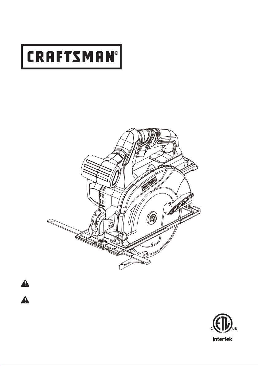
OPERATOR′S MANUAL
MANUAL DEL USUARIO
20V MAX* LITHIUM-ION
CORDLESS CIRCULAR SAW
20 V MÁX* DE IONES DE LITIO
SIERRA CIRCULAR INALÁMBRICA
Model No. 125.46569
Número de modelo. 125.46569
WARNING:
the Operator’s Manual before using this product.
ADVERTENCIA:
comprender el manual antes de utilizar este producto.
Sears Brands Management Corporation, Hoffman Estates, IL 60179 USA
Save this manual for future reference.
Conserve este manual para futura referencia.
* Maximum initial battery voltage (measured without workload) is 20 volts.
Nominal working voltage is 18 volts.
* La tensión inicial máxima de la batería (medida sin carga) es 20 voltios.
La tensión de trabajo nominal es 18 voltios.
To reduce the risk of injury, the user must read and understand
Para reducir el riesgo de lesiones, el usuario debe leer y
Page 2

TABLE OF CONTENTS / TABLA DE CONTENIDOS
ENGLISH
■ Warranty ................................................................ 2
■ Introduction ............................................................ 2
■ Safety Instructions .............................................. 3-6
■ Symbols .............................................................. 7-8
■ Features ................................................................ 9
■ Assembly ............................................................. 10
■ Operation For Circular Saw ..............................11-16
■ Care & Maintenance ............................................17
■ Troubleshooting ..............................................18
■ Illustrated Parts List...............................................19
■ Figure Numbers (Illustrations) ............................ i-v
CRAFTSMAN LIMITED WARRANTY
FOR ONE YEAR from the date of sale this power tool is warranted against defects in material or
workmanship.
WITH PROOF OF SALE a defective product will be replaced free of charge.
For warranty coverage details to obtain free replacement, visit the web page:
www.craftsman.com/warranty
This warranty does not cover the blade, which is an expendable part that can wear out from normal use within
the warranty period.
This warranty applies for only 90 days from the date of sale if this product is ever used while providing
commercial services or if rented to another person.
This warranty gives you specic legal rights, and you may also have other rights which vary from state to
state.
Sears Brands Management Corporation, Hoffman Estates, IL 60179
GARANTÍA LIMITADA CRAFTSMAN
DURANTE UN AÑO a contar de la fecha de venta, esta herramienta y la batería incluida con ella están
garantizadas contra defectos en sus materiales o fabricación.
Un producto defectuoso será reemplazado de manera gratuita contra presentación de una PRUEBA DE
VENTA.
Para conocer la cobertura de la garantía y obtener un reemplazo gratuito, visite el sitio Web:
www.craftsman.com/warranty
Esta garantía no cubre la broca, la cual es una pieza desechable que puede desgastarse debido al uso
normal dentro del periodo de garantía.
La garantía se aplica durante un periodo de solo 90 días si el producto se usa para proporcionar servicios
comerciales o si se le arrienda a otra persona.
Esta garantía le entrega derechos legales especícos que pueden variar según su estado (podría tener otros
derechos adicionales).
Sears Brands Management Corporation, Hoffman Estates, IL 60179
ESPAÑOL
■ Garantía ............................Sección de Inglés pág. 2
■ Introducción ......................Sección de Inglés pág. 2
■ Instrucciones de seguridad ................................ 3-7
■ Símbolos ............................................................ 8-9
■ Características ......................................................10
■ Armado ................................................................ 11
■ Funcionamiento De La Sierra Circular..............12-18
■ Cuidado Y Mantenimiento.................................19
■ Resolución de problemas.................................20
■ Lista de piezas, ilustrada..........................19
■ Números de las guras (ilustraciones)................ i-v
* * *
INTRODUCTION / INTRODUCCIÓN
This tool has many features for making its use more pleasant and enjoyable. Safety, performance, and
dependability have been given top priority in the design of this product making it easy to maintain and
operate.
* * *
Esta herramienta tiene muchas funciones para hacerla más agradable y cómoda de usar. Se ha dado
máxima prioridad a la seguridad, rendimiento y dependencia en las etapas de diseño de este producto
para que sea fácil de utilizar y mantener.
2 ― English
Page 3

SAFETY INSTRUCTIONS
WARNING
Read and understand all instructions. Failure to
follow all instructions listed below may result in
electric shock, re and/or serious personal injury.
Save all warnings and instructions for future
reference. The term “power tool” in the
warnings refers to your mains-operated
(corded) power tool or battery-operated
(cordless) power tool.
WORK AREA SAFETY
■ Keep work area clean and well lit. Cluttered
or dark areas invite accidents.
■ Do not operate power tools in explosive
atmospheres, such as in the presence of
ammable liquids, gases or dust. Power
tools create sparks which may ignite the dust
or fumes.
■ Keep children and bystanders away while
operating a power tool. Distractions can
cause you to lose control.
ELECTRICAL SAFETY
■ Power tool plugs must match the outlet.
Never modify the plug in any way. Do not
use any adaptor plugs with earthed
(grounded) power tools. Unmodied plugs
and matching outlets will reduce risk of
electric shock.
■ Avoid body contact with earthed or grounded
surfaces such as pipes, radiators, ranges
and refrigerators. There is an increased risk
of electric shock if your body is earthed or
grounded.
■ Do not expose power tools to rain or wet
conditions. Water entering a power tool will
increase the risk of electric shock.
■ Do not abuse the cord. Never use the cord
for carrying, pulling or unplugging the power
tool. Keep cord away from heat, oil, sharp
edges or moving parts. Damaged or
entangled cords increase the risk of electric
shock.
■ When operating a power tool outdoors,
use an extension cord suitable for outdoor
use. Use of a cord suitable for outdoor use
reduces the risk of electric shock.
■ If operating a power tool in a damp location
3 ― English
is unavoidable, use a ground fault circuit
interrupter (GFCI) protected supply. Use of
a GFCI reduces the risk of electric shock.
PERSONAL SAFETY
■ Stay alert, watch what you are doing and
use common sense when operating a
power tool. Do not use tool while tired or
under the inuence of drugs, alcohol, or
medication. A moment of inattention while
operating power tools may result in serious
personal injury.
■ Use personal protective equipment. Always
wear eye protection. Protective equipment
such as dust mask, non-skid safety shoes,
hard hat, or hearing protection used for
appropriate conditions will reduce personal
injuries.
■ Prevent unintentional starting. Ensure the
switch is in the off-position before
connecting to power source and/or battery
pack, picking up or carrying the tool.
Carrying power tools with your nger on the
switch or energizing power tools that have
the switch on invites accidents.
■ Remove any adjusting key or wrench
before turning the power tool on. A wrench
or a key left attached to a rotating part of
the power tool may result in personal injury.
■ Do not overreach. Keep proper footing
and balance at all times. This enables
better control of the power tool in
unexpected situations.
■ Dress properly. Do not wear loose clothing
or jewelry. Keep your hair, clothing and
gloves away from moving parts. Loose
clothes, jewelry or long hair can be caught
in moving parts.
■ If devices are provided for the connection
of dust extraction and collection facilities,
ensure these are connected and properly
used. Use of these devices can reduce dust
related hazards.
POWER TOOL USE AND CARE
■ Use only with compatible Craftsman 20V
Max powered by DieHard slide-type lithiumion battery packs.
■ Do not use the power tool if the switch
Page 4

SAFETY INSTRUCTIONS
does not turn it on and off. Any power tool
that cannot be controlled with the switch is
dangerous and must be repaired.
■ Disconnect the plug from the power source
and/or the battery pack from the power tool
before making any adjustments, changing
accessories, or storing power tools. Such
preventive safety measures reduce the risk
of starting the power tool accidentally.
■ Store idle power tools out of the reach of
children and do not allow persons unfamiliar
with the power tool or these instructions
to operate the power tool. Power tools are
dangerous in the hands of untrained users.
■ Maintain power tools. Check for
misalignment or binding of moving parts,
breakage of parts and any other condition
that may affect the power tool’s operation.
If damaged, have the power tool repaired
before use. Many accidents are caused by
poorly maintained power tools.
■ Keep cutting tools sharp and clean.
Properly maintained cutting tools with sharp
cutting edges are less likely to bind and are
easier to control.
■ Use the power tool, accessories and
tool bits etc. in accordance with these
instructions, taking into account the working
conditions and the work to be performed.
Use of the power tool for operations
different from those intended could result in
a hazardous situation.
■ Hold the power tool by the insulated
gripping surfaces when performing an
operation where the saw blade may come
into contact with hidden wiring. If the blade
contacts a "live" wire, it may activate the
exposed metal parts of the power tool and
could give the operator an electric shock.
■ Know your power tool. Read the Operator's
Manual carefully. Learn its applications
and limitations, as well as the specic
potential hazards related to this power tool.
Following this rule will reduce the risk of
electric shock, re, or serious injury.
■ Always wear eye protection with side
shields marked to comply with ANSI Z87.1
when assembling parts, operating the tool,
or performing maintenance. Following
this rule will reduce the risk of serious
personal injury.
■ Protect your lungs. Wear a face or dust
mask if the operation is dusty. Following
this rule will reduce the risk of serious
personal injury.
■ Protect your hearing. Wear hearing
protection during extended periods of
operation. Following this rule will reduce
the risk of serious personal injury.
■ Battery tools do not have to be plugged
into an electrical outlet; therefore, they
are always in operating condition. Be
aware of possible hazards when not
using your battery tool or when changing
accessories. Following this rule will
reduce the risk of electric shock, re, or
serious personal injury.
■ Do not use on an unstable support. Stable
footing on a solid surface enables better
control of the power tool in unexpected
situations.
■ Do not force the power tool. Use the
correct power tool for your application.
The correct power tool will do the job
better and safer at the rate for which it
was designed.
CIRCULAR SAW USE AND CARE
CUTTING PROCEDURES
DANGER
Keep hands away from cutting area and the
blade. Keep your second hand on auxiliary
handle, or motor housing. If both hands are
holding the saw, they cannot be cut by the
blade.
■ Do not reach underneath the workpiece.
The guard cannot protect you from the
blade below the workpiece.
■ Adjust the cutting depth to the thickness
of the workpiece. Less than a full tooth of
the blade teeth should be visible below
the workpiece.
■ Never hold the piece being cut in your
hands or across your leg. Secure
4 ― English
Page 5

SAFETY INSTRUCTIONS
the workpiece to a stable platform. It is
important to support the workpiece properly
to minimize body exposure, blade binding,
or loss of control.
■ When ripping, always use a rip fence or
straight edge guide. This improves the
accuracy of cut and reduces the chance of
blade binding.
■ Always use blades with correct size and
shape (diamond versus round) of arbour
holes. Blades that do not match the
mounting hardware of the saw will run
eccentrically, causing loss of control.
■ Never use damaged or incorrect blade
washers or bolt. The blade washers and
bolt were specially designed for your saw,
for optimum performance and safety of
operation.
KICKBACK CAUSES AND RELATED
WARNING
■ Kickback is a sudden reaction to a pinched,
bound or misaligned saw blade, causing
an uncontrolled saw to lift up and out of the
workpiece toward the operator;
■ When the blade is pinched or bound tightly
by the kerf closing down, the blade stalls
and the motor reaction drives the unit
rapidly back toward the operator;
■ If the blade becomes twisted or misaligned
in the cut, the teeth at the back edge of the
blade can dig into the top surface of the
wood causing the blade to climb out of the
kerf and jump back toward the operator.
Kickback is the result of saw misuse and/or
incorrect operating procedures or conditions
and can be avoided by taking proper
precautions as given below:
■ Maintain a rm grip with both hands on
the saw and position your arms to resist
kickback forces. Position your body to
either side of the blade, but not in line with
the blade. Kickback could cause the saw
to jump backwards, but kickback forces
can be controlled by the operator, if proper
precautions are taken.
■ When blade is binding, or when interrupting
a cut for any reason, release the trigger and
hold the saw motionless in the material until
the blade comes to a complete stop. Never
attempt to remove the saw from the work or
pull the saw backward while the blade is in
motion or kickback may occur. Investigate
and take corrective actions to eliminate the
cause of blade binding.
■ When restarting a saw in the workpiece,
center the saw blade in the kerf and check
that saw teeth are not engaged into the
material. If the saw blade is binding, it may
walk up or kickback from the workpiece as
the saw is restarted.
■ Support large panels to minimize the risk
of blade pinching and kickback. Large
panels tend to sag under their own weight.
Supports must be placed under the panel
on both sides, near the line of cut and near
the edge of the panel.
■ Do not use dull or damaged blades.
Unsharpened or improperly set blades
produce narrow kerf causing excessive
friction, blade binding and kickback.
■ Blade depth and bevel adjusting locking
levers must be tight and secure before
making cut. If blade adjustment shifts while
cutting, it may cause binding and kickback.
■ Use extra caution when sawing into existing
walls or other blind areas. The protruding
blade may cut objects that can cause
kickback.
LOWER GUARD FUNCTION
■ Check the lower guard for proper closing
before each use. Do not operate the saw if
the lower guard does not move freely and
close instantly. Never clamp or tie the lower
guard into the open position. If the saw is
accidentally dropped, the lower guard may
be bent. Raise the lower guard with the
retracting handle and make sure it moves
freely and does not touch the blade or any
other part, in all angles and depths of cut.
■ Check the operation of the lower guard
spring. If the guard and the spring are not
operating properly, they must be serviced
before use. Lower guard may operate
sluggishly due to damaged parts, gummy
5 ― English
Page 6

SAFETY INSTRUCTIONS
deposits, or a build-up of debris.
■ Lower guard should be retracted manually
only for special cuts such as “plunge cuts”
and “compound cuts”. Raise lower guard
by retracting handle and as soon as blade
enters the material, the lower guard must
be released. For all other sawing, the lower
guard should operate automatically.
■ Always observe that the lower guard is
covering the blade before placing saw
down on bench or oor. An unprotected,
coasting blade will cause the saw to walk
backwards, cutting whatever is in its path.
Be aware of the time it takes for the blade
to stop after the switch is released.
ADDITIONAL SAFETY WARNINGS
■ Use clamps or other practical ways to
secure and support the workpiece to a
stable platform. Holding the workpiece by
hand or against your body is unstable and
may lead to loss of control.
■ Do not place battery tools or their batteries
near re or heat. This will reduce the risk of
explosion and possibly injury.
■ Do not crush, drop or damage a battery
pack. Do not use a battery pack or charger
that has been dropped or received a sharp
blow. A damaged battery is subject to
explosion. Properly dispose of a dropped or
damaged battery immediately.
■ Batteries can explode in the presence of
a source of ignition, such as a pilot light.
To reduce the risk of serious personal
injury, never use any cordless product in
the presence of open ame. An exploded
battery can propel debris and chemicals. If
exposed, ush with water immediately.
■ Do not charge battery tool in a damp or wet
location. Following this rule will reduce the
risk of electric shock.
■ For best results, your battery tool should
be charged in a location where the
temperature is between 40°F (4°C) and
100°F (38°C). To reduce the risk of serious
personal injury, do not store outside or in
vehicles.
■ Under extreme usage or temperature
conditions, battery leakage may occur. If
liquid comes in contact with your skin, wash
immediately with soap and water. If liquid
gets into your eyes, ush them with clean
water for at least 10 minutes, then seek
immediate medical attention. Following this
rule will reduce the risk of serious personal
injury.
Save these instructions.
Refer to them frequently and use them to
instruct others who may use this product.
If you loan someone this product, loan them
these instructions also.
CALIFORNIA PROPOSITION 65
WARNING
Drilling, sawing, sanding or machining wood
products can expose you to wood dust, a
substance known to the State of California
to cause cancer. Avoid inhaling wood dust
or use a dust mask or other safeguards for
personal protection.
For more information go to:
www.P65Warnings.ca.gov/wood
Wash hands after handling.
6 ― English
Page 7
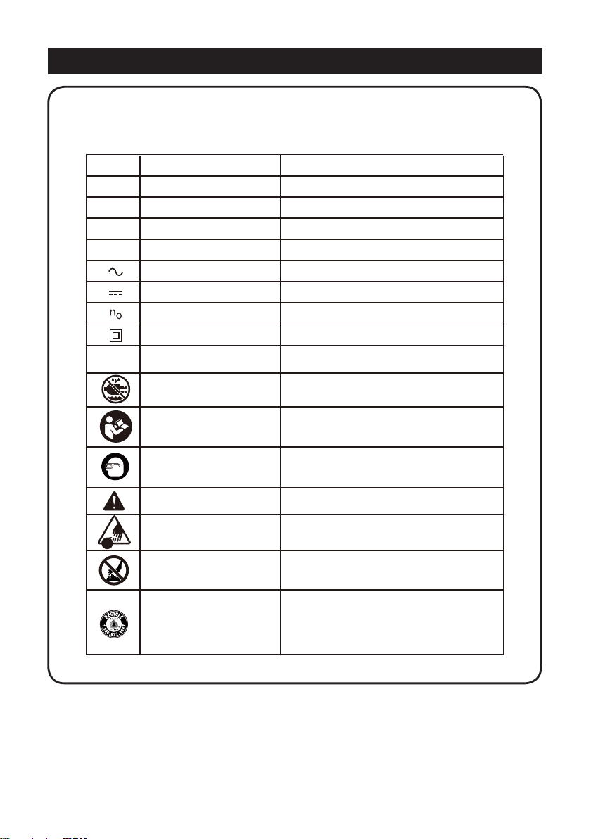
SYMBOLS
Some of the following symbols may be used on this product. Please study them and
learn their meaning. Proper interpretation of these symbols will allow you to operate
the product better and safer.
SYMBOL NAME DESIG NATION/EXP LANATION
V Volts Voltage
A Amperes Current
Hz Hertz Frequency (cycles per second)
W Watt Power
min Minutes Time
Alternating Current Type of current
Direct Current Type or a c haracteristic of c urrent
Rotational speed, at no load
Revolutions, s trokes, surface speed,
orbits, etc., per minute
Do not expose to rain or use in damp
locations.
To reduce the risk of injur
ad and understand operator’s manual
re
before using this product.
y, user must
.../mi n
No-load Speed
Class II C onstruction Double-insulated construction
Per Minute
Wet Conditions Alert
Read The O perator’s Manual
Eye protection
Safety Alert Prec autions that involve your safety.
No-Hands Symbol
Hot Surface
Recycle Symbol
Always wear eye protection with side
shields marked to comply with ANSI Z87.1.
Failure to keep your hands away from the
blade will result in serious personal injury.
To reduce the risk of injury or damage,
avoid contact with any hot surface.
This product uses lithium-ion batteries. Local,
state, or federal laws may prohibit disposal of
batteries in ordinary trash. Consult your local
waste authority for information regarding
available recycling and/or disposal options.
7 ― English
Page 8

SYMBOLS
The following signal words and meanings are intended to explain the levels of risk
associated with this product.
SYMBOL SIGNAL MEANING
DANGER
Indicates an imminently hazardous situation, which, if not
avoided, will result in death or serious injury.
WARNING
CAUTION
NOTICE
Indicates a potentially hazardous situation, which, if not
avoided, could result in death or serious injury.
Indicates a potentially hazardous situation, which, if not
avoided, may result in minor or moderate injury.
(Without Safety Alert Symbol) Indicates a situation that may
result in property damage.
8 ― English
Page 9

FEATURES
PRODUCT SPECIFICATIONS
Circular Saw
Model No. .................................................................................................................
Type...................................................................................................Cordless, battery-powered
Motor.................................................................................................................... 20 V max* d.c.
Blade Diameter...............................................................................................................6-1/2 in.
Blade Arbor........................................................................................................................5/8 in.
Maximum Cutting Depth at 0°.............................................................................................. 2 in.
Maximum Cutting Depth at 45°......................................................................................1-1/3 in.
No Load Speed............................................................................................................3300 rpm
Weight (with included battery)...........................................................................................6.8 lbs
125.46569
KNOW YOUR CIRCULAR SAW
See Figure 1, page i
The safe use of this product requires an
understanding of the information on the
product labeling and in this Operator's Manual
as well as a knowledge of the project you
are attempting. Before use of this product,
familiarize yourself with all operating features
and safety rules.
BEVEL ADJUSTMENT
The bevel adjustment allows you to set the
circular saw for bevel cuts from 0° to 45°.
BLADE WRENCH STORAGE
Convenient wrench storage for quick blade
changes.
DEPTH ADJUSTMENT KNOB
The depth adjustment knob adjusts the depth
of cut from 0 in. to 2 in.
SAFETY SWITCH
The safety switch reduces the possibility of
accidental starting.
SPINDLE LOCK BUTTON
The spindle lock button allows you to secure
the blade when turning the blade screw.
WIDTH OF CUT GUIDE
When making straight cross cuts or rip cuts,
the guide can be used to measure up to 4 in.
on the right side of the blade, and up to 1 in.
on the left side of the blade.
TRIGGER SWITCH
Depress the safety switch, and then squeeze
the trigger switch to start the saw. To stop it,
release the trigger switch.
LOWER BLADE GUARD
The lower blade guard attached to the circular
saw is covering the blade for your protection
and safety.
9 ― English
Page 10

ASSEMBLY
UNPACKING
This product requires assembly.
■ Carefully remove the product and any
accessories from the box. Make sure
that all items listed in the packing list are
included.
WARNING:
if any parts on the Packing List are already
assembled to your product when you unpack
it. Parts on this list are not assembled to the
product by the manufacturer and require
customer installation. Use of a product that
may have been improperly assembled could
result in serious personal injury.
■ Inspect the product carefully to make sure
no breakage or damage occurred during
shipping.
■ Do not discard the packing material until
you have carefully inspected and
satisfactorily operated the product.
■ If any parts are damaged or missing, do not
operate the product. Return it for
replacement to the retailer from which it
was purchased.
Do not use this product
PACKING LIST
(1) 20V Cordless Circular Saw
(1) Circular Saw Blade
(1) Rip Fence
(1) Blade Wrench
(1) Operator's Manual
WARNING:
missing, do not attempt to attach the battery
pack or operate the tool until the broken or
missing parts are replaced. Failure to do so
could result in possible serious injury.
If any parts are broken or
WARNING:
modify this tool or create accessories not
recommended for use with this tool. Any such
alteration or modication is misuse and could
result in a hazardous condition leading to
possible serious injury.
Do not attempt to
10 ― English
Page 11

OPERATION FOR CIRCULAR SAW
This product will accept compatible Craftsman
20V Max powered by DieHard slide-type
lithium-ion battery packs. For complete charging
instructions, refer to the Operator's Manual for
your battery pack and charger models.
WARNING:
starting that could cause serious personal
injury, always remove the battery pack from
the tool when assembling parts, making
adjustments, installing or removing saw
blade, cleaning, or when it is not in use.
TO ATTACH BATTERY PACK
See Figure 2, page ii
To install the battery pack, align the tongue
on the battery pack with the groove in the
housing and slide it into place. Insert it all the
way until it locks in place with a click.
NOTICE:
battery pack snaps into place and the battery
pack is secured to the tool before beginning
operation. Improper assembly of the
battery pack can cause damage to internal
components.
TO DETACH BATTERY PACK
See Figure 2, page ii
To remove the battery pack, slide it from the
tool while pressing the button on the front of
the pack.
WARNING:
operating condition. To prevent accidental
starting, always ensure the safety switch is
not depressed when the tool is not in use or
when carrying the tool at your side. Always
carry the tool by its handgrip.
ATTACHING THE BLADE
See Figure 3, page ii
WARNING:
maximum blade capacity of the saw. Never
use a blade that is too thick to allow outer
blade washer to engage with the ats on the
spindle. Larger blades will come in contact
To prevent accidental
Make sure that the latch on the
Battery tools are always in
A 6-1/2 in. blade is the
11 ― English
with the blade guard, while thicker blades will
prevent blade screw from securing blade on
spindle. Either of these situations could result
in a serious accident.
■ Remove the battery pack from the saw.
■ Obtain the blade wrench (5mm hex key)
from storage area. See Figure 1, page i.
■ Depress and hold the spindle lock button.
■ Insert blade wrench into blade screw head
and turn clockwise to loosen and remove
screw.
NOTE:
mechanism pin engages.
■ Remove the outer blade washer.
■ Use the lower blade guard lever to rotate
■ Carefully remove the old blade (if present)
WARNING
can cut ngers if touched.
■ Release the lower blade guard to allow
NOTICE:
or spindle lock, always allow motor to come
to a complete stop before engaging spindle
lock.
NOTE:
spindle lock engaged.
■ Wipe a drop of oil onto the inner blade
WARNING:
has been removed, replace it before placing
the blade on the spindle. The larger diameter
of the inner blade washer should be placed
against the blade. Failure to do so could
cause an accident as the blade will not
tighten properly.
■ Use the lower blade guard lever to rotate
■ Carefully t the saw blade onto the spindle
The spindle may turn until lock
and hold the guard all the way to the left.
from saw.
: Blade teeth are sharp and
guard to swing back into place.
To prevent damage to the spindle
Do not run the circular saw with the
washer and outer blade washer where they
contact the blade.
If the inner blade washer
guard all the way to the left.
and under the lower blade guard. Insert the
blade so that the teeth point upward at the
front of the saw as shown in Figure 3, E.
Page 12

OPERATION FOR CIRCULAR SAW
WARNING
can cut ngers if touched.
■ Release the lower blade guard lever to
allow guard to swing back into place.
■ Replace the outer blade washer onto
spindle.
■ Thread the blade screw counterclockwise
into spindle. Depress and hold the spindle
lock button.
■ Use the blade wrench to tighten blade
screw securely.
: The spindle may turn until lock
NOTE
mechanism pin engages.
■ Return the blade wrench to the storage
area.
: Never use a blade that is too thick to
NOTE
allow the outer blade washer to engage with
the ats on the spindle.
: Blade teeth are sharp and
REMOVING THE BLADE
See Figure 4, page ii.
■ Remove the battery pack from the saw.
■ Obtain the blade wrench (5mm hex key)
from storage area. See Figure 1, page i.
■ Depress and hold the spindle lock button.
■ Insert the blade wrench into blade screw
head and turn clockwise to loosen and
remove screw.
: The spindle may turn until lock
NOTE
mechanism pin engages.
■ Remove the outer blade washer.
■ Use the lower blade guard lever to rotate
and hold the guard all the way to the left.
■ Carefully remove blade from the saw.
WARNING
can cut ngers if touched.
■ Release the lower blade guard to allow
guard to swing back into place.
: Blade teeth are sharp and
KICKBACK
See Figures 5 - 8, pages ii - iii
Kickback occurs when the blade stalls rapidly
and the saw is driven back towards you.
Blade stalling is caused by any action which
pinches the blade in the wood.
DANGER:
if blade binds or saw stalls. Kickback could
cause you to lose control of the saw. Loss of
control can lead to serious injury.
Release switch immediately
To guard against kickback, avoid
dangerous practices such as the
following:
■ Setting blade depth incorrectly.
■ Sawing into knots or nails in the workpiece.
■ Twisting the blade while making a cut.
■ Making a cut with a dull, gummed up, or
improperly set blade.
■ Supporting the workpiece incorrectly.
■ Forcing a cut.
■ Cutting warped or wet lumber.
■ Operating the tool incorrectly or misusing
the tool.
To lessen the chance of kickback,
follow these safety practices:
■ Keep blade at the correct depth setting.
The depth setting should not exceed 1/4 in.
below the material being cut.
■ Inspect the workpiece for knots or nails
before cutting. Never saw into a knot or
nail.
■ Make straight cuts. Always use the rip
fence when rip cutting. This helps prevent
twisting the blade.
■ Use clean, sharp, and properly set blades.
Never make cuts with dull blades.
■ Support the workpiece properly before
beginning a cut.
■ Use steady, even pressure when making a
cut. Never force a cut.
■ Do not cut warped or wet lumber.
■ Hold the saw rmly with both hands and
keep your body in a balanced position so
as to resist the forces if kickback should
occur.
WARNING:
always stay alert and exercise control. Do not
remove the saw from the workpiece while the
blade is moving.
When using the saw,
SAW BLADES
The best of saw blades will not cut efciently
12 ― English
Page 13

OPERATION FOR CIRCULAR SAW
if they are not kept clean, sharp, and properly
set. Using a dull blade will place a heavy
load on the saw and increase the danger of
kickback. Keep extra blades on hand, so that
sharp blades are always available.
Gum and wood pitch hardened on blades will
slow the saw down. Remove saw blade from
the saw and use gum and pitch remover, hot
water, or other non-ammable cleaners to
remove these accumulations.
GASOLINE
.
DO NOT USE
BLADE GUARD SYSTEM
See Figure 9, page iii
The lower blade guard attached to the circular
saw is there for your protection and safety.
Do not alter it for any reason. If it becomes
damaged, do not operate the saw until you
have the guard repaired or replaced. Always
leave guard in operating position when using
the saw.
DANGER:
workpiece, the lower blade guard does not
cover the blade on the underside of the
workpiece. Since the blade is exposed on
the underside of the workpiece, keep hands
and ngers away from cutting area. Any part
of your body coming in contact with moving
blade will result in serious injury.
CAUTION:
is not operating correctly. Check the guard for
correct operation before each use. The guard
is operating correctly when it moves freely
and readily returns to the closed position.
If you drop the saw, check the lower blade
guard and bumper for damage at all depth
settings before reuse.
If at any time the lower blade guard does not
snap closed, remove the battery from the
saw. Exercise the lower guard by moving
it rapidly back and forth from the full open
position to the closed position several times.
Normally this will restore the guard to its
When sawing through the
Never use saw when guard
normal operating condition. If it does not
correct a slow or sluggish closing lower
guard, do not use the saw. Take it to an
authorized factory service center for repair.
STARTING/STOPPING THE SAW
See Figure 10, page iii
To start the saw:
■ Depress the safety switch.
■ Squeeze the trigger switch.
Always let the blade reach full speed, and
then guide the saw into the workpiece.
WARNING:
contact with the workpiece before it reaches
full speed could cause the saw to “kickback”
toward you resulting in serious injury.
To stop the saw:
After you release the trigger switch, allow the
blade to come to a complete stop. Do not
remove the saw from the workpiece while the
blade is moving.
The blade coming in
Release the trigger switch.
SAFETY SWITCH
See Figure 10, page iii
The safety switch reduces the possibility
of accidental starting. The safety switch
is located on the handle above the trigger
switch. The safety switch must be depressed
before you pull the trigger switch. The lock
resets each time the trigger is released.
You can depress the safety switch
NOTE:
from either the left or right side.
ADJUSTING BLADE DEPTH
See Figure 11, page iii
Always keep correct blade depth setting.
The correct blade depth setting for all cuts
should not exceed 1/4 in. below the material
being cut. More blade depth will increase
the chance of kickback and cause the cut to
be rough. For more depth of cut accuracy,
a guide is located on the back of the upper
blade guard.
■ Remove the battery pack from the saw.
13 ― English
Page 14

OPERATION FOR CIRCULAR SAW
■ Loosen the depth adjustment knob.
■ Determine the desired depth of cut.
■ Locate the depth of cut guide on back of
upper blade guard.
■ Hold base at against the workpiece and
raise or lower saw until the indicator mark
on bracket aligns with pointer on blade
guard.
■ Tighten the depth adjustment knob
securely.
OPERATING THE SAW
See Figures 12 - 14, page iii - iv
It is important to understand the correct
method for operating the saw. Refer to the
gures in this section to learn the correct and
incorrect ways for handling the saw.
DANGER:
the workpiece, the blade is exposed on the
underside of the saw until the lower blade
guard closes. Make sure the lower blade
guard is closed before setting the saw down.
WARNING:
safer, always maintain proper control of the
saw. Loss of control could cause an accident
resulting in possible serious injury.
To make the best possible cut, follow these
helpful hints:
■ Hold the saw rmly with both hands.
■ Avoid placing your hand on the workpiece
while making a cut.
■ Support the workpiece so that the cut (kerf)
is always to your side.
■ Support the workpiece near the cut.
■ Clamp the workpiece securely so that the
workpiece will not move during the cut.
■ Always place the saw on the workpiece that
is supported, not the “cut off” piece.
■ Place the workpiece with the “good” side
down.
■ Draw a guideline along the desired line of
cut before beginning your cut.
When lifting the saw from
To make sawing easier and
CROSS CUTTING/RIP CUTTING
See Figure 15, page iv
When making a cross cut or rip cut, align the
line of cut with the outer blade guide notch on
the base.
Since blade thicknesses vary, always make a
trial cut in scrap material along a guideline to
determine how much, if any, you must offset
the guideline to produce an accurate cut.
The distance from the line of cut to
NOTE:
the guideline is the amount you should offset
the guide.
RIP CUTTING
See Figure 16, page iv
Use a guide when making long or wide rip
cuts with the saw.
■ Secure the workpiece.
■ Clamp a straight edge to the workpiece
using C-clamps.
■ Saw along the straight edge to achieve a
straight rip cut.
Do not bind the blade in the cut.
NOTE:
WIDTH OF CUT GUIDE
See Figure 17, page iv
A width of cut guide has been provided on
the base of your saw. When making straight
cross cuts or rip cuts, the guide can be used
to measure up to four inches to the right side
of the blade. It can be used to measure up to
one inch to the left side of the blade.
ADJUSTING THE RIP FENCE
See Figure 18, page iv.
The supplied rip fence can be used for rip
cutting or bevel cutting.
■ Loosen the rip fence locking knob.
■ Slide the rip fence into the slot and set it
to the desired length. Tighten the locking
knob.
For sawing with the blade totally
NOTE:
vertical, i.e. at 90°, read the guide from notch
C. For sawing at a bevel angle of 45°, read
the guide from notch B.
14 ― English
Page 15

OPERATION FOR CIRCULAR SAW
BEVEL CUTTING
See Figures 19 - 20, page v
■ Align the line of cut with the inner blade
guide notch on the base when making 45°
bevel cuts.
■ Make a trial cut in scrap material along
a guideline to determine how much you
should offset the guideline on the cutting
material.
■ Adjust the angle of the cut to any desired
setting between 0° to 45°. Refer to
Adjusting the Bevel Setting
next.
ADJUSTING THE BEVEL SETTING
See Figure 19, page v
■ Remove the battery pack from the saw.
■ Loosen the bevel adjustment knob.
■ Raise the motor housing end of the saw
until you reach the desired angle setting on
the bevel guide.
■ Tighten the bevel adjustment knob securely.
WARNING:
without having the bevel adjustment knob
securely tightened can result in serious injury.
Attempting a bevel cut
MAKING A BEVEL CUT
See Figure 20, page v
■ Hold the saw rmly with both hands as
shown.
■ Rest the front edge of the base on the
workpiece.
■ Start the saw and let the blade reach full
speed.
■ Guide the saw into the workpiece and make
the cut.
■ Release the trigger and allow the blade to
come to a complete stop.
■ Lift the saw from the workpiece.
POCKET CUTTING
See Figure 21, page v
WARNING:
setting to zero before making a pocket cut.
Attempting a pocket cut at any other setting
Always adjust bevel
can result in loss of control of the saw
possibly causing serious injury.
■ Remove the battery pack from the saw.
■ Adjust the bevel setting to zero.
■ Set the blade to the correct blade depth
setting.
■ Reinsert the battery pack.
■ Swing the lower blade guard up using the
lower blade guard lever.
NOTE:
with the lever to avoid serious injury.
■ Hold the lower blade guard by the lever
WARNING:
while holding the lower blade guard lever.
Extending your ngers could result in contact
with the blade, causing serious injury.
■ Rest the front of the base at against the
■ Start the saw and let the blade reach full
■ Guide the saw into workpiece, release
WARNING:
direction when pocket cutting. Cutting in the
reverse direction could cause the saw to
climb up on the workpiece and back toward
you.
■ Release the trigger and allow the blade to
■ Lift the saw from the workpiece.
■ Clear corners out with a hand saw or saber
WARNING:
blade guard in a raised position. Leaving the
blade exposed could lead to serious injury.
Always raise the lower blade guard
while holding the saw rmly with both
hands as shown.
Never extend your ngers
workpiece with the rear of the handle raised
so the blade does not touch the workpiece.
speed.
lower blade guard lever, and make the cut.
Always cut in a forward
come to a complete stop.
saw.
Never tie or retain the lower
15 ― English
Page 16

OPERATION FOR CIRCULAR SAW
ADJUSTING POSITIVE 0° BEVEL STOP
WARNING:
adjustment, make sure the battery pack
is removed from tool. Failure to heed this
warning could result in serious personal
injury.
Before performing any
POSITIVE 0° BEVEL STOP
See Figure 22, page v
The saw has a positive 0° bevel stop that
has been factory adjusted to assure 0° angle
of the saw blade when making 0° (right
angle) cuts.
To check positive 0° bevel stop:
■ Remove the battery pack from the saw.
■ Place the saw in an upside down position
on a work-bench.
■ Check the squareness of the saw blade
to the base of the saw using a carpenter′s
square.
To adjust positive 0° bevel stop:
■ Remove the battery pack from the saw.
■ Loosen the bevel adjustment knob.
■ Loosen the hex nut securing the adjustment
screw.
■ Turn the adjustment screw and adjust the
base until square with the saw blade.
■ Tighten the hex nut and the bevel
adjustment knob securely.
WARNING:
without having the bevel adjustment knob
securely tightened can result in serious injury.
Attempting a bevel cut
16 ― English
Page 17

CARE & MAINTENANCE
WARNING:
identical replacement parts as listed in this
manual. Use of any other parts may create a
hazard or cause product damage.
WARNING:
injury, always remove the battery pack from
the tool when cleaning or performing any
maintenance.
When servicing, use only
To avoid serious personal
GENERAL MAINTENANCE
Avoid using solvents when cleaning plastic
parts. Most plastics are susceptible to damage
from various types of commercial solvents
and may be damaged by their use. Use clean
cloth to remove dirt, dust, oil, grease, etc.
WARNING:
uids, gasoline, petroleum-based products,
penetrating oils, etc. come in contact with
plastic parts. Chemicals can damage, weaken
or destroy plastic which may result in serious
personal injury.
Only the parts shown on the parts list are
intended to be repaired or replaced by the
customer. All other parts should be replaced
at the Sears Service Center.
WARNING:
identical replacement parts as listed in this
manual. Use of any other parts may create a
hazard or cause product damage. To ensure
Do not at any time let brake
When servicing, use only
safety and reliability, all repairs should be
performed by a qualied service technician.
STORAGE
■ Remove the battery pack from the tool
before storing.
■ Clean all foreign material from the tools.
■ Store the tools and its accessories in a dry,
frost free place.
■ Always store the tools in a place that is
inaccessible to children. The ideal storage
temperature is between 40°F (4°C) and
100°F (38°C).
■ Keep tools away from corrosive agents
such as garden chemicals and de-icing
salts.
■ We recommend using the original package
for storage or covering the product with a
suitable cloth to protect it against dust.
TRANSPORTATION
■ Set the rotation selector to OFF and
remove battery pack before transporting
tool anywhere.
■ Ordinarily, always carry the tool by its
handgrip. If the tool is tted with a belt
hook, it may be hung from your belt.
■ Protect the tool from any heavy impact or
strong vibrations which may occur during
transportation in vehicles.
17 ― English
Page 18

TROUBLESHOOTING
PROBLEM CAUSE SOLUTION
The battery is defective. Replace with a new, charged battery.
Tool will not turn on.
The saw is sluggish and/or
cuts out.
Motor overheats.
The switch is dead. Tool must be replaced.
Brushes are worn out. Tool must be replaced.
Worn/damaged saw blade.
Too much force applied. Decrease the applied force.
Cooling vents are clogged with saw
dust or debris, or are being covered
by hand during operation.
Check the blade and replace with a
new blade if necessary.
Clear vents with compressed air.
Do not cover vents with hand during
operation.
18 ― English
Page 19

CRAFTSMAN 20V MAX* LITHIUM-ION CORDLESS CIRCULAR SAW-MODEL NUMBER 125.46569
4
The model number will be found on a label attached to the motor housing.
TO PURCHASE REPLACEMENT PARTS, CALL 1-888-331-4569
1
3
2
ITEM NO. PART NO. DESCRIPTION QTY
1 125.CC20A-B
2 411006102
3 411006103
4 411006104
Circular Saw Tool Body
Flange Set
Saw Blade
Rip Fence
19 ― English
1
1
1
1
Page 20

See this section for all of the gures referenced in the
Operator's Manual.
(Consulte esta sección para ver todas las guras mencionadas
en el manual del usuario.)
Fig. 1
D
B
C
A
A. Bevel Adjustment Knob (Perilla de ajuste de bisel)
B. Spindle Lock Button (Botón de bloqueo del husillo)
C. Width of Cut Guide (Anchura de la guía de corte)
D. Safety Switch (Interruptor de seguridad)
E. Trigger Switch (Gatillo interruptor)
F. Lower Blade Guard (Protección de la hoja inferior)
G. Rip Fence (Guía de rasgado)
H. Blade Wrench Storage (Almacenamiento de la llave de la hoja)
I. Depth Adjustment Knob (Perilla de ajuste de profundidad)
E
H
F
G
I
i
Page 21

Fig. 2
Fig. 3
A
C
B
A. Battery Pack (not included) (Paquete de baterías (no incluido))
B. To install (Para instalación)
C. Depress Battery Release Button to remove
(Presione el botón de liberación de la batería para quitarlas)
A. Spindle Lock Button (Botón de bloqueo del husillo)
B. Lower Blade Guard (Protección de la hoja inferior)
C. Spindle (Eje rotor)
D. Inner Blade Washer (Arandela de la hoja interior)
E. Blade (Hoja)
F. Outer Blade Washer (Arandela de la hoja exterior)
G. Blade Screw (Tornillo de la hoja)
H. Lower Blade Guard Lever
(Palanca de la protección de la hoja inferior)
Fig. 4 Fig. 6
A
F
B
E
C
A
C
H
INCORRECT SUPPORT
SOPORTE INCORRECTO
(
B
D
E
F
G
)
D
A. Spindle Lock Button (Botón de bloqueo del husillo)
B. Blade Screw (Tornillo de la hoja)
C. Lower Blade Guard (Protección de la hoja inferior)
D. To tighten (Para apretar)
E. To loosen (Para aflojar)
F. Lower Blade Guard Lever
(Palanca de la protección de la hoja inferior)
Fig. 5
(CONTRAGOLPE - HOJA AJUSTADA DEMASIADO PROFUNDAMENTE)
KICKBACK - BLADE SET TOO DEEP
WRONG
INCORRECTO
(
)
ii
Page 22

CORRECT BLADE DEPTH SETTING = BLADE EXPOSED 1/4 in.
(6.35MM) OR LESS ON UNDERSIDE OF WORKPIECE
CONFIGURACIÓN DE PROFUNDIDAD DE LA HOJA CORRECTA
= HOJA EXPUESTA DE 1/4 pulg. (6,35 MM) O MENOS EN EL
EXTERIOR DE LA PIEZA DE TRABAJO
Fig. 8Fig. 7
CORRECT SUPPORT
SOPORTE CORRECTO
Fig. 9
A
B
A.
Lower blade guard is in up position when making a cut
(El protector inferior de la hoja está en posición elevada al hacer
un corte)
B. Blade exposed on underside of workpiece
(Hoja expuesta en la parte inferior de la pieza de trabajo)
Fig. 11
C
A
B
Fig. 10
B
A. Safety Switch (Interruptor de seguridad)
B. Trigger Switch (Gatillo interruptor)
Fig. 12
A
A. Depth Adjustment Knob (Perilla de ajuste de profundidad)
B. Depth of Cut Guide (Profundidad de la guía de corte)
C. Guide Pointer (Puntero de la guía)
WRONG
INCORRECTO
iii
Page 23

Fig. 13 Fig. 14
Fig. 15
TOP VIEW OF SAW
VISTA SUPERIOR DE LA SIERRA
Fig. 16
A
B
C
A. Blade Guide Notch (Muesca de la guía de la hoja de sierra)
B. Guideline (Línea de la guía)
C. Front of Saw (Hoja frontal)
A. Straight Edge (Borde recto)
B. Cut Line (Línea de corte)
C. C-Clamp (Abrazadera en C)
Fig. 17 Fig. 18
A
WRONG
(INCORRECTO)
C
A
C
B
C
B
A
A. Width of Cut Guide (Anchura de la guía de corte)
A. Rip Fence Locking Knob
(Muesca de bloqueo de la guía de rasgado)
B. Notch for sawing at a bevel angle of 45°
(Muesca para cortar en un ángulo de bisel de 45°)
C. Notch for sawing at a vertical angle of 90°
(Muesca para cortar en un ángulo vertical de 90°)
iv
Page 24

Fig. 19
Fig. 20
E
A. Bevel Adjustment Knob
(Perilla de ajuste de bisel)
B. Bevel Guide
(Guía del bisel)
C. Blade Guide Notch
(Muesca de la guía de
D
A
la hoja de sierra)
D. Guideline
(Línea de la guía)
E. Motor Housing
(Carcasa del motor)
A
B
C
B
C
A. Bevel Guide (Guía del bisel)
B. Bevel Adjustment Knob (Perilla de ajuste de bisel)
C. Blade Guide Notch (Muesca de la guía de la hoja de sierra)
Fig. 22Fig. 21
D
C
A
B
C
B
A
A. Lower Blade Guard Lever
(Palanca de la protección de la hoja inferior)
B. Pocket Cut (Corte de bolsillo)
C. Lower Blade Guard (Protección de la hoja inferior)
F
A. Adjustment Screw (Tornillo de ajuste)
B. Hex Nut (Tuerca hexagonal)
C. 0° Bevel Guide Position (Posición de la guía del bisel de 0°)
D. Bevel Adjustment Knob (Perilla de ajuste de bisel)
E. Blade (Hoja)
F. Carpenter's Square (not included)
(Escuadra de carpintero (no incluida))
v
E
 Loading...