

Craftsman 124.3299 Owner's Manual
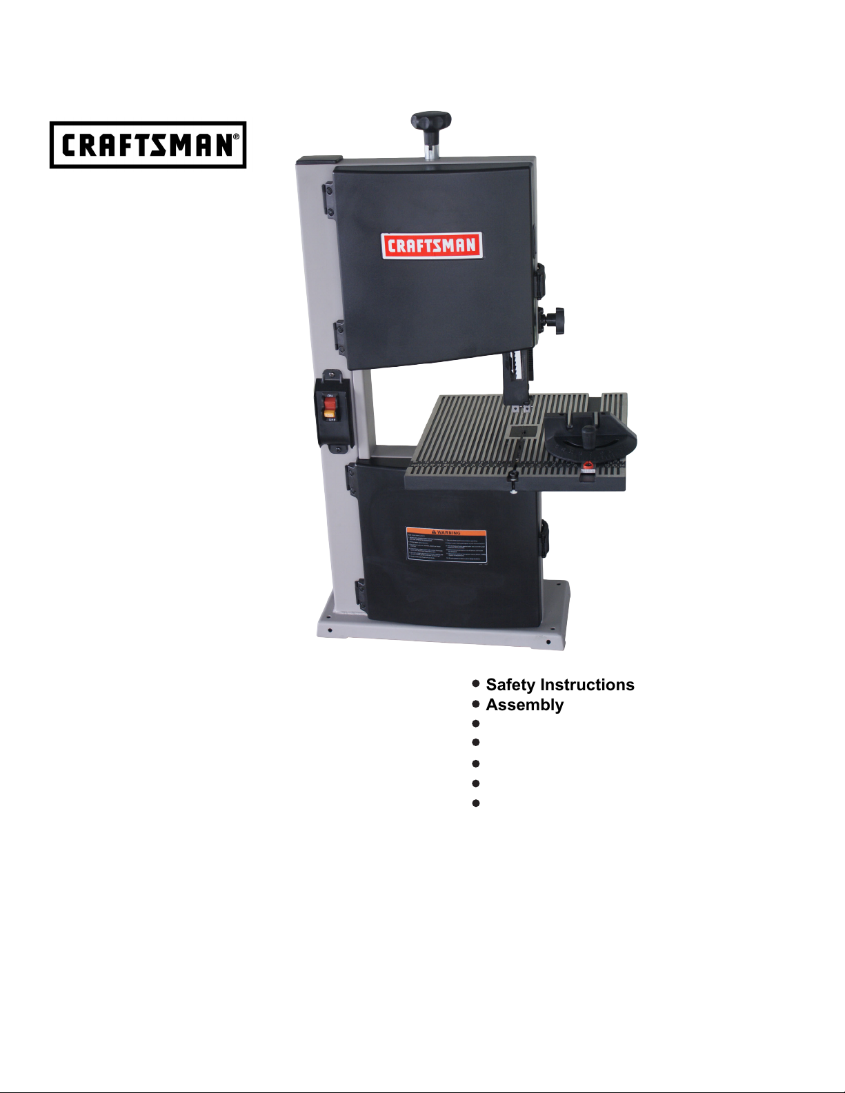
Operator’s Manual
9-in. BENCH TOP
BAND SAW
1/4 HP MOTOR
Model 124.3299
CAUTION: Before using this
product, read this manual and
follow all its Safety Rules
and Operating Instructions.
Sears Brands Management Corporation,
Hoffman Estates, IL 60179 U.S.A
WARNING: Some dust created by power sanding, sawing, grinding, drilling, and other construction activities contains
chemicals known to the State of California to cause cancer and birth defects or other reproductive harm.
Advertencia: Algunos polvo creado al lijar, serrado, recticado, taladrado, y otras actividades de construcción contiene
sustancias químicas que se sabe que el Estado de California, que causa cáncer y defectos de nacimiento u otros daños
reproductivos.
Safety Instructions
Assembly
Operation
Maintenance
Troubleshooting
Parts List
Espanol (PG. 22)
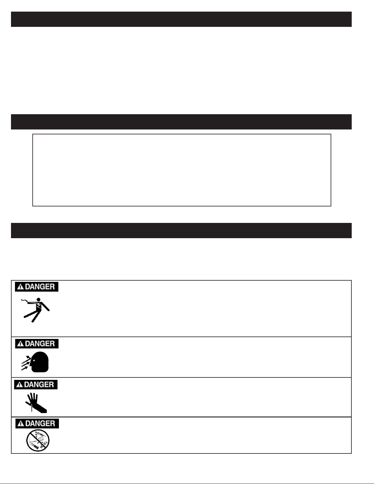
TABLE OF CONTENTS
Warranty..........................................................................................................................................................................................2
Safety Instructions.....................................................................................................................................................................................2-3
Sp e cificat ions... . ...... . ...... . ...... . ....... ....... . ...... . ...... . ...... . ....... ....... . ...... . ...... . ...... . ....... ....... ....... . ...... . ...... . ...... . ....... ...3
Assembly...................................................................................................................................................................................................4-5
Know Your Band Saw....................................................................................................................................................................6
Adjustments.............................................................................................................................................................................................6-8
Operation...................................................................................................................................................................................................8
Maintenance...............................................................................................................................................................................................9
Electrical Schematic..................................................................................................................................................................................9
Troubleshooting.........................................................................................................................................................................................10
Repair Protection Agreements....................................................................................................................................................................10
Notes.....................................................................................................................................................................................................11
Parts Diagrams..............................................................................................................................................................12-21
FULL ONE YEAR WARRANTY
ONE-YEAR FULL WARRANTY ON CRAFTMAN PROFESSIONAL TOOL
FOR ONE YEAR from the date of purchase, this product is warranted against any defects in material or workmanship. A defective
product will receive free repair or replacement if repair is unavailable.
For warranty coverage details to obtain free repair or replacement, visit the web site: www. craftsman. com
This warranty does not cover the blade, which is an expendable part that can wear out from normal use within the warranty period.
This warranty is void if this product is ever used while providing commercial services or if rented to another person.
This warranty gives you specic legal rights, and you may also have other rights which vary from state to state.
Sears Brands Management Corporation, Hoffman Estates, IL 60179
For Questions/Comments or Technical Assistance - Please Call Customer Service at: 1-877-866-8392 (M-F 8:30AM-5PM EST.)
GENERAL SAFETY WARNINGS
KNOW YOUR POWER TOOL
potential hazards.
Always Ground All Tools.
If your tool is equipped with a three-pronged plug, you must plug it into a three-hole electric receptacle. If you use
an adapter to accommodate a two-pronged receptacle, you must attach the adapter plug to a known ground. Never
remove the third prong of the plug.
Always Avoid Dangerous Environments.
Never use power tools in damp or wet locations. Keep your work area well lighted and clear of clutter.
Always Remove the Adjusting Keys and Wrenches from Tools after Use.
Form the habit of checking to see that keys and adjusting wrenches are removed from the tool before turning it on.
Always Keep Your Work Area Clean.
Read the owner’s manual carefully. Learn the tool’s applications, work capabilities, and its specic
.
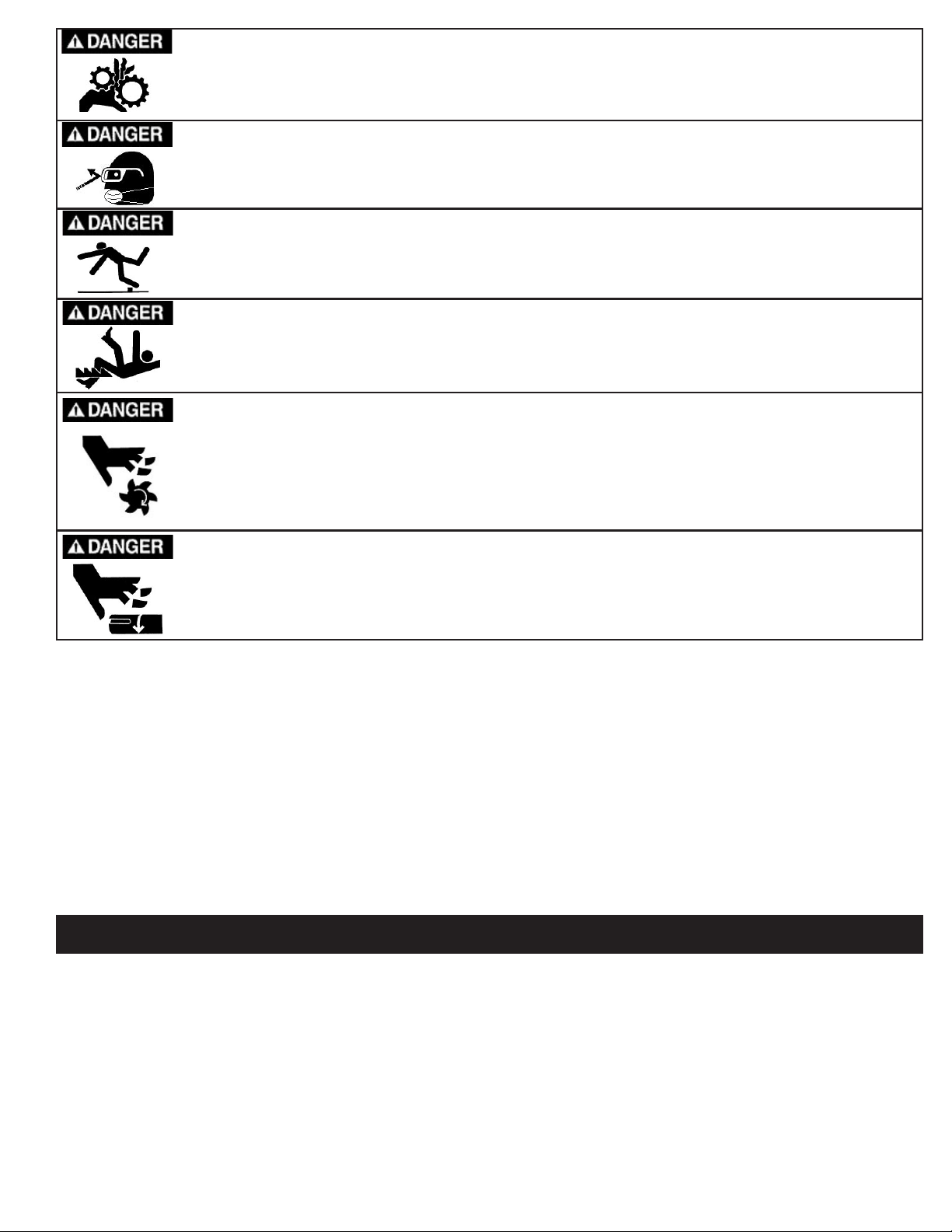
SAFETY INSTRUCTIONS
Cluttered areas and benches invite accidents.
Always Keep Visitors Away from Running Machines.
All visitors should be kept a safe distance from the work area.
Always make the Workshop Childproof.
Childproof
with padlocks, master switches, or by removing starter keys.
Never operate a tool while under the inuence of drugs, medication, or alcohol.
2
Always Wear Proper Apparel.
Never wear loose clothing or jewelry that might get caught in moving parts. Rubber-soled footwear is recommended
for the best footing.
Always Use Safety Glasses and Wear Hearing Protection.
Also use a face or dust mask if the cutting operation is dusty.
Never Overreach.
Keep your proper footing and balance at all times.
Never Stand on Tools.
Serious injury could occur if the tool is tipped or if the cutting tool is accidentally contacted.
Always Disconnect Tools
Disconnect tools before servicing and when changing accessories such as blades, bits, and cutters.
Always Avoid Accidental Starting.
Make sure switch is in “OFF” position before plugging in cord.
Never Leave Tools Running Unattended.
Always Check for Damaged Parts.
Before initial or continual use of the tool, a guard or other part that is damaged should be checked to assure that it
will operate properly and perform its intended function. Check for alignment of moving parts, binding of moving parts,
breakage of parts, mounting, and any other conditions that may affect its operation. A guard or other damaged parts
should immediately be properly repaired or replaced.
.
SPECIAL SAFETY RULES FOR BAND SAWS
1. Always stop the band saw before removing scrap pieces from table.
2. Always keep hands and ngers away from the blade.
3. Never attempt to saw stock that does not have a at surface, unless a suitable support is used.
4. Always hold material rmly and feed it into the blade at a moderate speed.
5. Always turn off the machine if the material is to be backed out of an uncompleted cut.
6. Check for proper blade size and type for thickness and type of material being cut.
7. Make sure that the blade tension and blade tracking are properly adjusted.
8. Make “relief” cuts before cutting long curves.
9. Release blade tension when the saw will not be used for a long period of time.
10. Note and follow the safety warnings and instructions that appear on the lower door of this saw.
SPECIFICATIONS
Blade Length......................................................62"
Blade Width............................................1/8" to 3/8"
Throat Width...................................................8-3/4"
Cutting Depth.................................................3-1/2"
Blade Speeds.............................................1 Speed
Dust Port(1)..........................................................2"
Table Size......................................11-1/2" x 11-1/2"
Table Tilt.............................................0-45 Degrees
Motor.............................................................1/4 HP
Motor Voltage..................................................120V
Motor Amperage..............................................2.5 A
Net Weight....................................................44 LBS
SAVE THESE INSTRUCTIONS.
Refer to them often.
3
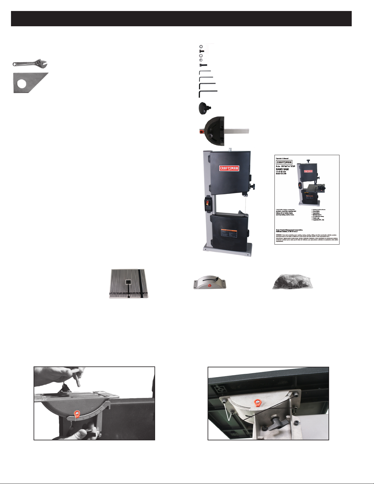
ASSEMBLY
1. TOOLS REQUIRED FOR ASSEMBLY
Item Description Qty.
Adjustable Wrench................................1
Square...................................................1
2. UNPACKING AND CHECKING CONTENTS
Model 124.3299 9” Band Saw is shipped complete in one box.
A.
Separate all parts from carton and check each item with Carton
Contents list below to make sure all items are accounted for, before
discarding any packing material.
B.
Remove the protective oil that is applied to the table. Use any
ordinary household type grease and spot remover.
C.
Apply a coat of paste wax to the table to prevent rust. Wipe all
parts thoroughly with a clean dry cloth.
CARTON CONTENTS
Item Description Qty.
LIST OF LOOSE PARTS IN BAG
Item Description Qty.
Washer M6.......................................4
Hex Bolt M6x12................................4
Flat Washer M6................................1
Hex Nut M6.......................................1
Hex Bolt M6x20................................1
M2 Hex "L" Wrench..........................1
M2.5 Hex "L" Wrench.......................1
M4 Hex "L" Wrench..........................1
M5 Hex "L" Wrench..........................1
Blade Tension Knob.........................1
Miter Gauge.....................................1
A Main Machine w/Blade Installed................................1
B Operator’s Manual...............................................1
C Table......... . . . . ............ . . . . ............ . . . . . ...........1
D Upper Table Trunnion Assembly...............................1
E Bag of Loose Parts....................................................1
A
B
C D E
3. INITIAL ASSEMBLY
The 124.3299 band saw is supplied partly assembled. Prior to use, the following items have to be assembled: Table Trunnion, Table, and
Blade Tension Knob.
WARNING:
To avoid injury, do not attempt to run or use this machine until all parts are assembled and working properly.
FIG. 1
A.
Assemble the upper table trunnion to the lower table trunnion with
Carriage Bolt, Glide Piece, Washer and Wing Nut (See FIG. 1).
Table Bolts
(x4)
B.
Locate four bolts and four washers used to mount the table. Lay
FIG. 2
the table onto the upper table trunnion and install a bolt washer in
each hole, then tighten with “ L” wrench provided (See FIG. 2).
4
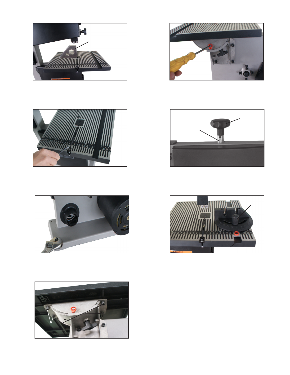
Square Table
to Blade
FIG. 3
C.
After the table is installed use a square to make sure that is 90
degrees to the blade (See FIG. 3).
FIG. 5
E.
Install the table leveling hex socket screw, washer and nut (See
FIG. 5).
FIG. 4
D.
Next, set the degree pointer until it reads zero degrees. Using a
Phillips screw driver loosen the pointer and set pointer to zero (See
FIG. 4).
FIG. 6
Metal Receiver
F.
Insert the blade tension handle into the metal receiver protruding
Blade Tension
Handle
from the top of the saw (See FIG. 6).
FIG. 8
Miter Gauge
FIG. 7
G.
To ensure upright stability, four holes are provided in the base to
allow the saw to be bolted to a bench (See FIG. 7).
Table Bolts
(x4)
I.
To center the blade in the table, locate four bolts and four washers
FIG. 9
used to mount the table. Loosen the bolts and center the table by
hand. Tighten the four bolts to retain adjustment (See FIG. 9.)
Miter Gauge Slot
H.
Slide the miter gauge into the miter gauge slot in the aluminum
table (See FIG. 8).
5
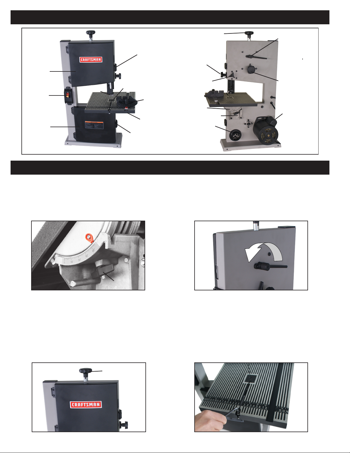
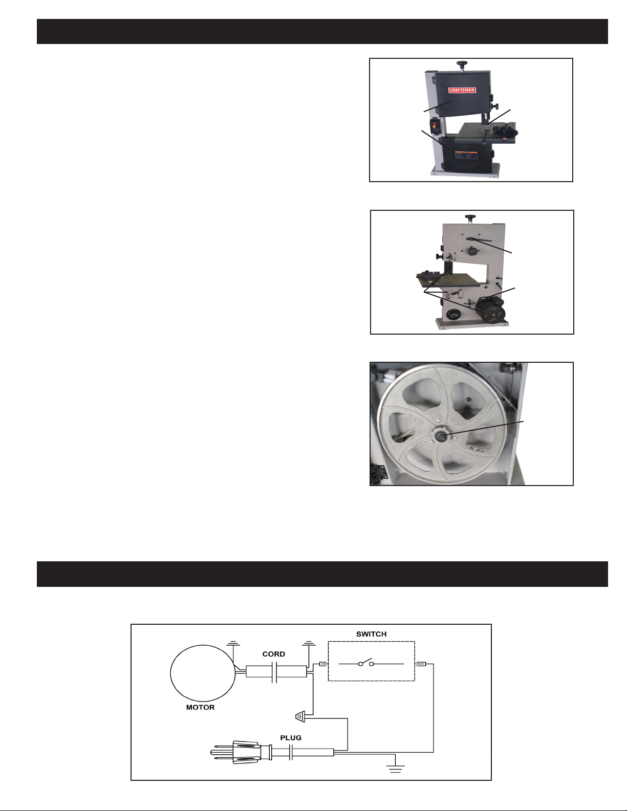
KNOW YOUR BAND SAW
Door Locking
Knob
Upper Bandwheel
Door
Switch
Lower Bandwheel
Door
Blade Guides
Table Insert
Table
Door Locking
Knob
Guide Post Adjusting Knob
Guide Post Locking Knob
Miter Gauge
ADJUSTMENTS
4. TILTING THE TABLE
For bevel cuts, the table tilts 0 through 45 degrees.
A.
To tilt the table, loosen the wing nut on the table trunnion, set the
table to the required angle and tighten the wing nut again (See FIG.
10).
Blade Tension Knob
Upper Table Trunnion
Lower Table Trunnion
2” Dust Port
Blade Quick Release
Blade Tracking
Knob
Motor
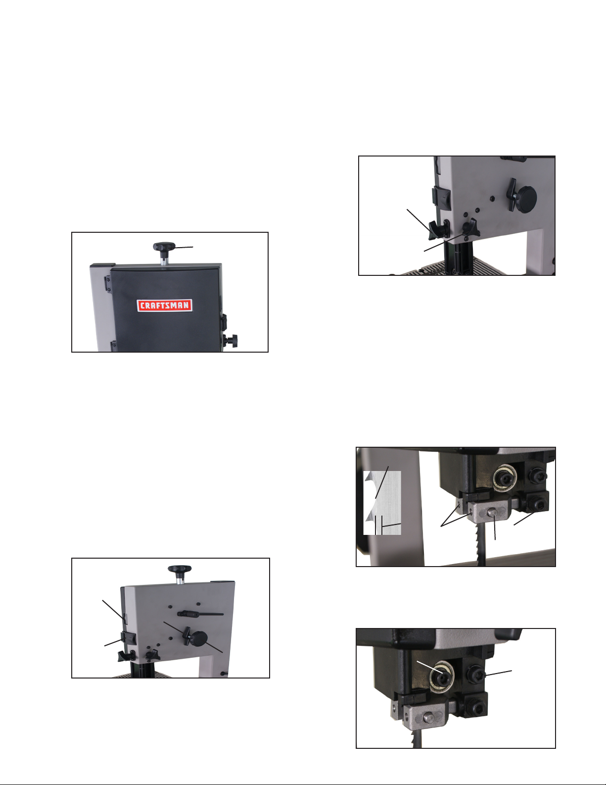
6. USING THE QUICK RELEASE LEVER
A.
This band saw equipped with a quick release blade tension feature. It is used to help speed up the removal and installation of the
saw blade.
FIG. 12
FIG. 10 Wing Nut
B.
It is recommended to verify the correct angle setting using an
angle guide, or by making trial cuts in scrap wood. Adjust the
indicator accordingly by using a phillips head screwdriver.
5. ADJUSTING THE BLADE TENSION
To loosen the tension of the blade, turn the blade tension knob
counterclockwise. To tighten the tension of the blade, turn the
tension knob clockwise (See FIG. 11).
FIG. 11
Blade Tension
Knob
ONOFF
B.
To operate the quick release and remove tension from the blade,
move the lever from the three o’clock position (ON) to the nine o’clock
position (OFF). Reverse direction to tension the blade (See FIG 12).
7. CHANGING AND ADJUSTING THE SAW BLADE
A.
This band saw is factory-equipped with a general-purpose wood
cutting blade, the saw blade is set prior to delivery. To change the
saw blade, begin by removing the table leveling hex socket screw,
washer and nut (See FIG. 13).
FIG. 13
6
WARNING:
To avoid injury from unexpected starting, whenever
changing the saw blade or carrying out adjustments, switch the
band saw off and remove the power cord from the power outlet. To
avoid injury to hands when handling the saw blade, wear gloves
whenever necessary.
B.
Open the upper and lower doors by releasing the door locking
knobs.
C.
Remove the blade tension by moving the quick release lever on
the upper rear wheel housing counter-clockwise until the saw blade
has slackened (See FIG. 12).
D.
Remove the saw blade from the upper and lower wheels.
E.
When installing the new saw blade ensure the blade teeth are
pointing downwards and towards you at the position where the saw
blade passes through the table.
8. SETTING THE CUTTING HEIGHT
A.
The upper blade guide should be set as close as practical above
the work piece.
B.
To adjust this height, loosen the guide post locking knob on the
back of the upper wheel housing. (See FIG. 16)
C.
Set the blade guides to the required height by turning the guide
post adjusting knob.
D.
Tighten the guide post locking knob after setting proper height.
FIG. 16
Guide Post
Adjusting Knob
FIG. 14
F.
Re-tension the new saw blade by turning quick release lever on
Blade Tension
Knob
the upper rear wheel housing clockwise. Check the saw blade
tracking by turning the upper wheel by hand.
G.
If more or less blade tension is needed, turn the blade tension
knob until desired tracking is made (See FIG. 14).
H.
If blade needs further tracking; proceed as mentioned below
“TRACKING THE BAND SAW BLADE”
8. TRACKING THE BAND SAW BLADE
Set the tracking of the saw blade before setting the blade guides.
Once the saw blade is installed and tensioned, track the saw blade
by adjusting the tracking knob by hand (See FIG. 15). The saw
blade should run in the center of the band saw wheels. Use the
blade tracking window to check position on wheel. When the correct
adjustment is achieved lock the tracking knob with the wing nut.
Blade
Tracking
Window
Wing Nut
FIG. 15
Guide Post
Locking Knob
9. ADJUSTING THE BLADE GUIDES
The Upper Blade Guide
A.
To adjust the upper blade guides, rst position the right and left
guide pins relative to the blade by loosening the lock screw
(SEE FIG. 17) and moving the guide carrier forward until both side
guide pins are approximately 1/16” behind the gullets of the saw
blade.
B.
Set both side guide pins to within 1/32” of the saw blade by
releasing the guide pin locking screw (SEE FIG. 17) on each side of
the saw blade and moving the guide pins to desired position. Lock
the guide pin in position with the guide pin locking screw. Do not set
the guide pins too close as this will adversely affect the life of the
saw blade.
Blade Gullet
1/16”
C.
Adjust the rear roller guide to be just clear of the back of the saw
blade by releasing the lock screw (SEE FIG. 18) and moving the
roller guide to approximately 1/32” behind the blade.
D.
When the correct adjustment is reached, lock the roller guide in
position with the guide lock screw (SEE FIG. 18).
Guide Pin
Locking
Screws
Lock Screw
Guide Pin (x2)
FIG. 17
Door
Locking
Knob
Tracking Knob
After it is determined that the blade is tracking in the center of both
wheels, close the upper and lower doors by latching the door locking knobs (See FIG. 15).
Rear Roller Guide
Lock Screw
FIG. 18
7
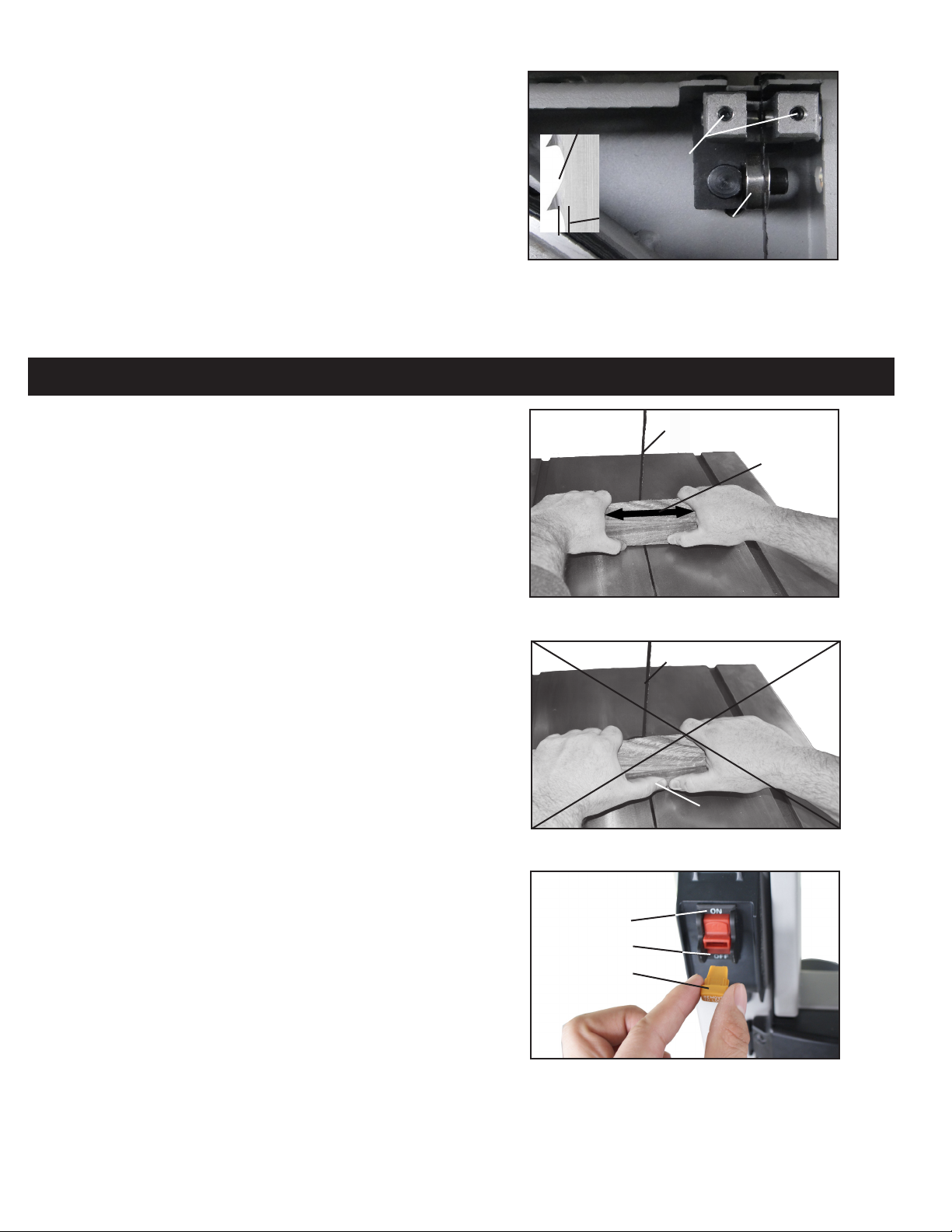
The Lower Blade Guide
A.
To adjust the upper blade guides, rst position the right and left
guide pins relative to the blade by loosening the lock screw
(SEE FIG. 19) and moving the guide carrier forward until both side
guide pins are approximately 1/16” behind the gullets of the saw
blade.
B.
Set both side guide pins to within 1/32” of the saw blade by
releasing the guide pin locking screw (SEE FIG. 19) on each side of
the saw blade and moving the guide pins to desired position. Lock
the guide pin in position with the guide pin locking screw. Do not set
the guide pins too close as this will adversely affect the life of the
saw blade.
C.
Adjust the rear roller guide to be just clear of the back of the saw
blade by releasing the lock screw and moving the roller guide to approximately 1/32” behind the blade.
OPERATION
FIG. 19
Blade Gullet
Guide Pin
Locking
Screws
1/16”
D.
When the correct adjustment is reached, lock the roller guide in
Rear Roller Guide
position with the guide lock screw.
WARNING:
Before starting check if any part of your band saw is
missing, malfunctioning, has been damaged or broken, such as
the motor, switch, or other operation control, a safety device or the
power cord, turn the band saw off and unplug it until the particular
part is properly repaired or replaced.
The saw blade cuts on a continuous downstroke. To avoid injury
when hands are unavoidably near to the saw blade, they should be
placed on either side of the blade (See FIG. 20), not in line with it
(See FIG. 21). Use a push stick whenever possible when working in
close proximity to the saw blade.
Start the band saw by lifting the switch to the ON position (See FIG.
22) and wait for the band saw to come to full speed before starting
to cut. Never start the band saw with the work piece in contact with
the saw blade.
Slowly feed the work piece towards the saw blade, putting only light
pressure on it. With both hands, rmly hold the work piece down on
the table, and feed it towards the saw blade slowly.
Once the cutting operation is complete turn the band saw off by
lowering the switch to the OFF position.
FIG. 20
FIG. 21
Blade
Correct
Blade
Incorrect
To prevent unauthorized use, remove the center key from the switch
(SEE FIG. 22).
For best results the saw blade must be sharp. Select the right saw
blade for the job, depending on the thickness of the wood the cut to
be made. The thinner and harder the wood, the ner the teeth (14
teeth per inch) of the saw blade. Use a ne tooth blade for cutting
sharp curves. For thick wood cutting use less teeth, approximately 4
teeth per inch.
The machine is especially suited for cutting curves, but will also
make straight cuts. Do not attempt to turn the work piece without
pushing it, as this may cause the work piece to get stuck, or the saw
blade to bend.
FIG. 22
ON
OFF
KEY
8
MAINTENANCE
WARNING:
To avoid injury due to unexpected starting, before
cleaning or carrying out maintenance work, switch off and disconnect
the band saw from the power source.
Never use water or other liquids to clean the band saw. Use a dry
brush.
Regular maintenance of the band saw will prevent unnecessary
problems.
A.
Keep the table clean to ensure accurate cutting.
B.
Keep the outside of the machine clean to ensure accurate opera-
tion of all moving parts and prevent excessive wear.
C.
Keep the ventilation slots of the motor clean to prevent it from
overheating.
D.
Keep the inside (near the saw blade, etc.) clean to prevent
accumulation of dust (See FIGS. 23 & 24). Use dust collection if possible.
E.
To prolong the life of the saw blade, when the band saw is not
in use for extended periods, release the saw blade tension (See
FIG. 24). Before reusing the band saw ensure that the blade is re-
tensioned and tracking is checked.
FIG. 23
Use Brush to
Clean Guides
Keep Inside
Areas Clean
FIG. 24
Blade Quick
Release Lever
Motor Belt
Tension Bolt
Keep Areas
Clean
14. CHANGING THE DRIVE BELT
A.
Release the saw blade tension by turning the blade tension knob
on the top of band saw counterclockwise.
B.
Release the drive belt tension by loosening motor belt tension bolt
(See FIG. 24)
C
. Using snap-ring pliers remove the installed snap-ring (See FIG. 25)
.
from the center of the lower wheel.
D.
Carefully slide the lower wheel forward and at the same time
release the saw blade from the wheel.
E.
Remove the old drive belt and install the new belt (ensure ribs in
drive belt are seated correctly before reassembling and tensioning the
drive belt).
F.
Slide the lower wheel back onto the lower wheel shaft making sure
the belt is placed around the motor pulley. Install the snap-ring.
G.
Follow procedures for CHANGING AND ADJUSTING THE SAW
BLADE & TRACKING THE BAND SAW BLADE, before restoring
power to the band saw and setting up for use.
ELECTRICAL SCHEMATIC
WARNING:
qualied electrician, using genuine replacement parts.
This machine must be grounded. To avoid electrocution or re, any repairs to electrical system should be done only by a
Snap-Ring
FIG. 25
9

TROUBLESHOOTING
Repair Protection Agreements
Congratulations on making a smart purchase. Your new
Craftsman
®
product is designed and manufactured for years of
dependable operation. But like all products, it may require repair
from time to time. That’s when having a Repair Protection
Agreement can save you money and aggravation.
Here’s what the Repair Protection Agreement* includes:
; Expert service by our 10,000 professional repair specialists
; Unlimited service and no charge for parts and labor on all
covered repairs
; Product replacement up to $1500 if your covered product
can’t be fixed
; Discount of 25% from regular price of service and related
installed parts not covered by the agreement; also, 25% off
regular price of preventive maintenance check
; Fast help by phone – we call it Rapid Resolution –
phone support from a Sears representative. Think of us
as a “talking owner’s manual.”
Once you purchase the Repair Protection Agreement, a
simple phone call is all that it takes for you to schedule service.
You can call anytime day or night, or schedule a service
appointment online.
The Repair Protection Agreement is a risk-free purchase. If
you cancel for any reason during the product warranty period,
we will provide a full refund. Or, a prorated refund anytime after
the product warranty period expires. Purchase your Repair
Protection Agreement today!
Some limitations and exclusions apply. For prices and
additional information in the U.S.A. call 1-800-827-6655.
*Coverage in Canada varies on some items. For full details
call Sears Canada at 1-800-361-6665.
Sears Installation Service
For Sears professional installation of home appliances, garage
door openers, water heaters, and other major home items, in the
U.S.A. or Canada call 1-800-4-MY-HOME
®
.
Problem Diagnosis Remedy
The machine does not work when switched
on.
The saw blade does not move with the
motor running.
The saw blade does not cut in a straight
line.
The saw blade does not cut, or cuts very
slowly.
Sawdust builds up inside the machine. This is normal Clean the machine regularly. Open the
Sawdust inside the motor housing. This is normal Clean the ventilating slots of the motor with
1. No power supply.
2. Defective switch.
3 Defective motor.
1. The blade tension knob has not been
tightened.
2. The blade has come off one of the
wheels.
3. The saw blade has broken.
4. The drive belt has snapped.
1. Rip fence for cutting not used.
2. Feed rate too fast.
3. The blade teeth are dull or damaged.
4. Blade guides not suitably adjusted.
1. The teeth are dull, caused by cutting
hard material or long use.
2. The saw blade was tted the wrong way
on the band saw.
1. Check the cable for breakage.
2. Replace the lock switch.
3. Defective motor.
1. Switch off the motor, tighten the blade
tension knob.
2. Open the doors and check.
3. Replace the blade.
4. Replace the belt.
1. Use a rip fence.
2. Put light pressure on the work piece.
Make sure the saw blade does not bend.
3. Try a new saw blade.
4. Adjust the blade guides (see ADJUSTMENT instructions).
1. Replace the saw blade, use a 6 T.P.I.
(Teeth Per Inch) saw blade for wood and
soft material. Use a 14 T.P.I. saw blade
for harder materials. A 14 T.P.I. saw blade
always cuts slower due to the ner teeth
and the slower cutting performance.
2. Fit the saw blade correctly.
doors and remove the sawdust with a
vacuum cleaner.
a vacuum cleaner. From time to time remove the sawdust to prevent it from being
drawn into the housing.
The machine does not cut at 45 or 90 degrees.
1. The table is not at right angles to the
blade.
2. The saw blade is dull or too much pressure was put on the work piece.
1. Adjust the table.
2. Replace the saw blade or put less
pressure on the work piece.
The saw blade can not be properly positioned on the wheels.
1. The wheels are not in alignment or defective bearing.
2. The blade tracking knob hasn’t been
properly adjusted.
3. Inferior saw blade.
1. Replace bearing.
2. Adjust the blade tracking knob (See
ADJUSTMENT instructions).
3. Replace the saw blade.
10

NOTES
Craftsman 9-inch Band Saw 124.3299
11
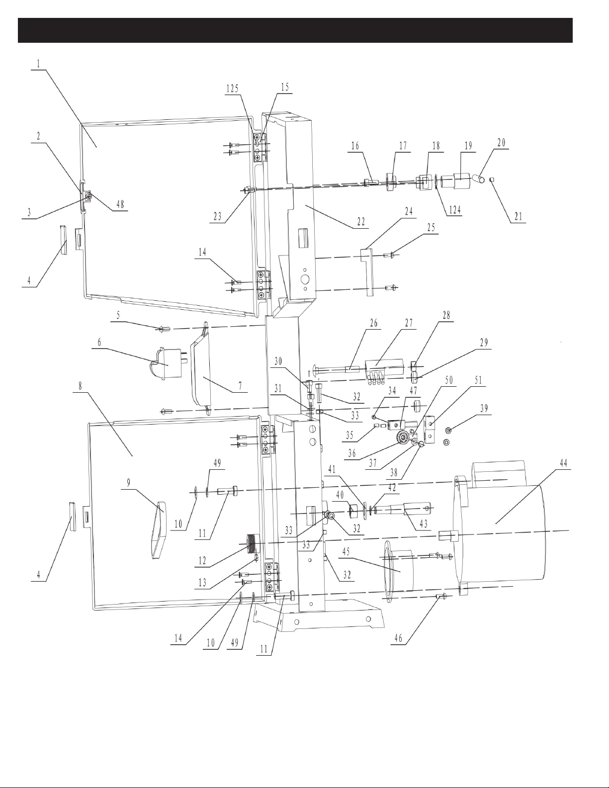
PARTS DIAGRAM A
Craftsman 9-inch Band Saw 124.3299
12

PARTS LIST A
KEY NO.
1
2
3
4
5
6
7
8
9
10
11
12
13
14
15
16
17
18
19
20
21
22
23
24
25
26
27
28
29
30
31
32
33
34
35
36
37
38
39
40
41
42
43
44
45
46
47
48
49
50
51
MFG. PART NO.
1-JMBS0901010001-001S
1-JMBS0901010009
1-ST3D5X9D5GB845B
1-JMBS0901010008
1-M5X8GB818B
1-HY7A
1-JMBS0901010005
1-JMBS0901010002-001S
1-JL22020003
1-WSH8GB97D1B
1-M8X25GB70B
1-JMBS0901020002
1-M5X8GB80B
1-M4X10GB819B
1-JMBS0901010007
1-M6X16GB70B
1-JMBS0901040003
1-JMBS0901040006
1-JMBS0901040004
1-JMBS0901040005
1-M5X6GB77B
1-JMBS0901011000-081Z
1-M5X8GB70D1B
1-JMBS0901050001
1-M5X10GB818B
1-M8X70GB14B
1-JL22010006
1-M8GB6177B
1-6N3-4
1-M6X10GB70B
1-WSH6GB97D1B
1-M6X16GB5783B
1-M6GB6170B
1-M4X6GB77B
1-PIN5X14GB119D1Z
1-BRG606-2ZGB276
1-WSH5GB97D1B
1-JMBS0901031003
1-M5X12GB70B
1-M12GB6170B
1-WSH12GB93B
1-CLP10GB894D1B
1-JMBS0901020004
2-YYG808024
1-JMBS0901010004
1-M5X10GB818B
1-JMBS0901031004
1-WSH4GB97D1B
1-WSH8GB93B
1-JMBS0901031002
1-JMBS0901031001
DESCRIPTION
Upper door
Clear window
Tapping screw 3.5x9.5
Handle
Pan head screw
Switch
Switch plate
Lower door
Drive belt
Flat washer
Hex bolt
Motor pulley
Hex. Bolt
Screw
Hinge
Hex. Socket set screw M6X16
Shaft tube
Fixing tube
Shaft
Lever
Hex. set screw M5X6
Frame
Hex. Socket set screw M5X8
Bafe
Pan head screw
Carriage bolt M8x70
Brush
Flange nut M8
Loop
Hex. Socket set screw
Flat washer
Hex. Socket set screw
Hex nut
Hex. set screw M4X6
Pin
Ball bearing
Flat washer
Screw
Hex. Socket set screw
Hex nut
Spring washer
Retaining ring
Lower bearing bolt
Motor
Dust port
Pan head screw
Glide piece
Flat washer
Spring washer
Shaft
Support piece
Craftsman 9-inch Band Saw 124.3299
13
 Loading...