

Page 1
Model No. 0220
Sears Item No. 123.24201
User’s Manual and Maintenance Guide
Questions? ..
Please call 1-800-422-3865
DO NOT RETURN TO THE STORE
Call B:00 am to 6:00 p.m Monday ihraughrFriday (Central Standard Time)
J
,i.ji I .
uafe.7 *
.
........ ‘-V-' -' ■- j
. t
• J . ,
...... ..................
11
. I I
'.•-y
\V,y-
Store this manual in the giove compartment of your tow vehicle
A Warning: For safe operation of this trailer, be sure to read all
/JAinstructions and warnings Failure to follow instiiictions and
warnings could result in property damage, serious injury and death
iiistrHCEmi)Ko I02S2U
5/1*1/2007
Page 2

Register your product at www.lifetime.conni.
wwwJifetinie.com
Page 3

Craftsman Metal Fold-Up Utility Trailer
Model No, 0220
Sears Item No, 123.24201
WARNING
This User’s Manual contains safety information and itisinictions for your trailer. You
must read this manual before loading or towing your trailer. You must follow all
safety precautions and instructions
For parts and service, call our customer service line at: 1-800-422-3865
NHTSA Notification Statement:
If you believe that your vehicle has a defect that couid cause a crash or could cause
injury or death, you should immediately inform the National Highway Tialfic Safety
AdmlnistTation (NHTSA) in addition to notifying Lifetime Products.
If NHTSA receives similar complaints, it may open an investigation, and if it finds
that a safety defect exists in a group of vehicles, it may order a recall and remedy
campaign, However, NHTSA cannot become involved irt individual problems
between you, Sears, or Lifetime Products.
To contact NHTSA, you may either call the Vehicle Safety Hotline toll-free at 1
888-327-4236 (TTY: 1 -800-424-l>I S3), go to hllp://www,,safecargov; or write to;
Administralor, NHTSA, 400 Seventh Street, SW-, Washington, DC 20590. You can
also obtain other information about motor vehicle safety from
Call 1-800-422-3865 to reach our Customer Service line.
http://www.safecargov.
Page 4

Table of Contents
SECTION 1: SAFETY INFORMATION 7
SECTION 2; TRAILER PARTS & HARDWARE II
^SECTIONS: FIRST-TIME SET-UP REQUIREMENTS 12
SECTION 4: TRAILER SETUP 17
SECTIONS: COUPLING TO THE TOW VEHICLE 19
5.1 Using an Adequate Tow Vehicle and Hitch 19
5.2 Coupling and Uncoupling the Trailer 19
5,2 / Trailer widt Ball-Hitch Coupler 19
5 2 11 Before coupling the trailer to the toM' vehicle 20
5 2 12 Prepare the coupler and hitch 20
5 2 1.3 CoupUng the trailer to the k»v vehicle 20
52 I 4 Rigging the safety chaim 2i
5 2.1.5 Connecting the electrical cables 22
3.2 1.6 Uncoupling the 'frailer 23
SECTION 6: TIRE & SAFETY INFORMATION 24
6.1 Determining Correct Load Limit “Trailer 24¡
6.1.1 Trailers ¡0,000 Fmimh GVÍVR or Less 24\
6.2 Determining Correct Load Limit-Tow Vehicle 24
6.3 Glossary of Tire Terra tiiology 24
6.4 Tire Safety - Everything Rides on It 27
6.4.1 Safety firsi-Basic tire mainteiiance 28
6.4.2 Finding your vehicle's recommended tire pressure and load limits 28
6.4.3 Understanding tire pressure and load iimits 28
6.4.4 Checking tire pressure 29
6.4.5 Steps for maintaining proper fire pressure 29
6.4.6 Tire size 29
6.4.7 Tire tread 30
6.4.8 Tire balance and wheel alignment 30
6.4.9 Tire repair 30
6.4.10 Tire Fundamentáis 30
6 4 JO / Information on Passenger Vehicle Tires 30
6 4 ¡02 VTQGS Information 3.2
6 4 10.3. Additional information on Light Truck Tires 32
6.4.11 Fire Safety Tips 33
6 4 11 1 Preventing Til e Damage 33
6 4 ¡12 Tire Safety Checklist ' 33
6.5 Changing a Flat Tire 33
6.6 Cheeking the Tire Pressure 35
SECTION?: LOADING THE TRAILER 36
7.1. CHECKING THE TONGUE WEIGHT 38
7JJ Checking Tongue Weight — Using a lever and bathroom scale 38
7.2 Securing the Cargo 38
7.2.1 Loading Cargo 38
7.2.!. I Preparing the Trailer for Loading
__
J9
Page 5

7.2 i, 2 Loading ¡he Trailer
SECTION S: CHECK TRAILER BEFORE & DURING TOWING
SECTIONS; BREAKING IN A NEW TRAILER
SECTION 10: MAINTENANCE
10.1 Inspection, Service & Maintenance Summary Charts
10.2 Inspection and Service Instructions
10.2.1 Axle Bolls, Frame, Suspemion, «£ Slructurc
10.2.2 Trailer StriicUire
10.2.2 I Fastener.'; and Frame hdembei;;
10.2.2.1 IVeld'i
10.2.3 Trailer Conmetion to Tow Vehicle
¡0 2.3 i Coupler and Ball
10.2.4 Landing Leg or Jack
10.2.5 Lights and Signals
10.2.6 Tires
10.2.7 Wheel Rims
10.2.8 Wheels, Bearings and Lug Nuts
10 2 8 i Unsealed Bearings (Hubs)
10.2.9 Lug Nuts (Bolts)
10.2.10 Suspemion
SECTION 11: EXPLODED TRAILER VIEWS
SECTION 12: WARRANTY INFORMATION
39
41
43
44
44
45
4.5
46
46\
46
47
■47
47
47
48
48
48
48
49
49
50
56
Page 6
Page 7
SECTIONIT^AFETY
INFORMATION
SAFETY ALERT SYMBOLS AND SIGNAL WORDS
The safety information in this
A
The level of risk is indicated by the following signal words:
SIGNAL WORDS
Warning
Caution
If a label becomes unreadable, you can re-order them fi-oni Customer Service:
1-800-422-3865
manual is denoted by the safety
alert symbol.
Hazards or unsafe practices
which COULD result in severe
personal injury or death if the
warning is ignored.
Hazards or unsafe practices
which could result in minor or
moderate injury if the warning is
ignored,
Warning Labels & Locations
Page 8
Lug Nuts and Tire Pressure
©
AWARNIMG
Tiro, wheel or iugnut failure can cause loss of
control Before towing^ you must CHECK;
1 Tire pressure and tread
2 Tires and wheels for damage
3 Lug nuts far tightness
PoE' new and remoynted wheels,
retighten lug nats at the first
IQ, 25 and SO miles of driving
Ф 2002 NAT>1
Re-ordcr #1025343
The proper tightness (torque) for !vig nuts is 95-120 ft ./lb. Do not exceed 120 li/lb.
Use a torque wrench to tighten the lug nuts, if you do not have a torque wrench, use
a !ug wrench (from youi tow vehicle) and tighten the nuts as much as you can. Then
have a service garage or trailer deafer tighten the lug nuts to the proper torque. See
the section on Tire and Safety Information for more details concerning tire safety
Lug nuts are also prone to loosen after fust being assembled When driving a new
trailer (or after wheels have been remounted), check to make sure they are tight after
the first 10, 25 and 50 miles of driving and before each toiv thereafter
Failure to perform this check can result in a wheel parting flrom the trailer and a crash,
leading to death or serious injury
yy
Tires and Wheels OK?
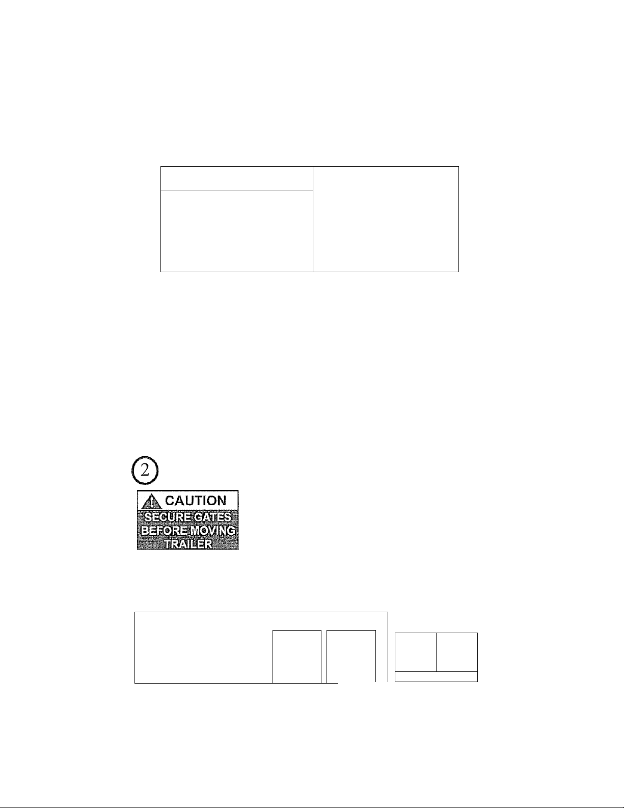
Securely Latching the Trailer Gate
Ensure the trailer gales are secure during towing. Failure
to insert gates securely could result in the load separating
from the trailer causing serious property damage, person
al injury and death,.
Re-order #1012296
Assist Wheel Caution
Always keep the Assist Wheel up when loading, unloading or towing the Trailer.
©
|A CAUTION
always load and tow the Trailer
while tlio Assist Wheel is up Failure
io heed this warning could resuii in
pcrfDMcnt damage to the Assisi Wheel
and void warranty
1
........................................................... ........... r .
vK( :
...
r-iSSSírí*“.’,' i
Part #102*1838
A
AcautionA
ÍQ
n
%
É\'
■c
ns
CL
Pa r t
#1025229
L'
Part#1025229
Page 9
Coupler, Load Weight and Distribution and Electrical
Connections
A WARNING
..
.
Re-order # 1024843
Loads can suddenly move or topple, which can result in death or seiious injitsy.
Overloaded nailers and improper tongue weight can result in loss of coiitiol of the
liailer Ensuie the trailer is coupled cotrectly a?sd the chains are crossed over each other
Ensure the load is tied securely and doesn't exceed the Gross Vehicle Weight (GVW)
Ensure the electricBl connections are lightly filled and fimciioning properly Always
check break Hgiits and turn signals before each tow
Pinch Point Warning
Folded Trailer Warning
A WARNING i
Г'“’™??'" 1
©
.......... mjNG
Watch for pinch
points while
folding or
deploying trailer
as serious injury
could occur
Always use the
Hand Crank
^vhen folding
and deploying
Trailer Ensure
others keep a safe
distance to avoid
any potential
pinch points
¿tyWARNlNGA
NEVER tow
Frailer while in
folded position
Failure to heed this
warning trtay' void
warranty and could
result in property
damage, serious
injury or death.
You can store
the Trailer in
folded position,
but do NOT tow
the Trailer while
rfs folded Tlie
Traiier may tip
ovei resulting in
property damage,
serious injury or
death
Pan ¿11025112
Part #1024837
Page 10
Tire and Loading Inforraatlon
illlllfHlilllil
No rc-ordcrs
Always check tire pressure lo ertsure optimum life and регГогтапсе from your tires
The tires that came with your trailer should have a tire pressure of 80 psi, Sears,
Roebuck and Co,, cannot be held responsible for damages caused by uneven tread
wear and blow outs from an under-in Plated or over-inflated tire
The Trailer and load should never exceed the Gross Vehicle Weight (GVW).,
Whenever loading the trailer, always check to see if you’re within this lirnii,. See the
section on Loading the Trailer for infomratioit regarding how to check
This sticker also displays your Vehicle Identification Numbes (VIN) in the boilom,
left-hand comer.
NATM Compliance
Re-order #]0!4245
Your trailer is in compliance with the
guidelines of the National Association of
Trailer Manufacturers Your trailer has its
own unique number Note: This is not
your Vehicle Identification Number (VIN)
Bail and Hitch Size
Your new trailer comes with a 2-inch coupler. The ball
on the tow vehicle must be 2 inches in diaTTieter, An
incoftect ball size can cause tlie separation of the trailer
ftom the tow vehicle resulting in possible property
' damage, serious injury and death,
10
Patent Advisory
LI F j:ti ts j E p li о i j V CT :
liiiiiiiiipiiiiiiiii
No re-orders
This sticker displays the various patents
applicable to the trailcr-
SL
O20i f
Re-order #1,013499
Page 11
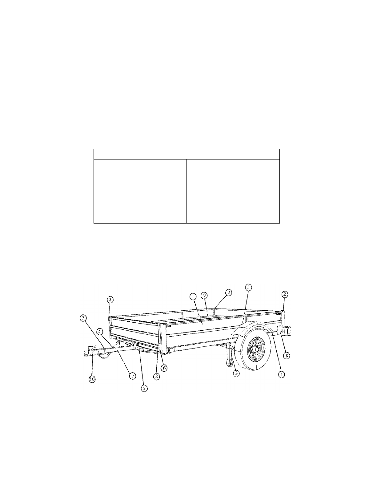
ECTION 2: TRAILER PARm^
HARDWARE
Before beginning assembly, inventory all parts using the Parts List and the Hardwai e Identifier (below) If al! parts are not presenL do NOT assemble the trailer
Cali L800-422-3865,
—
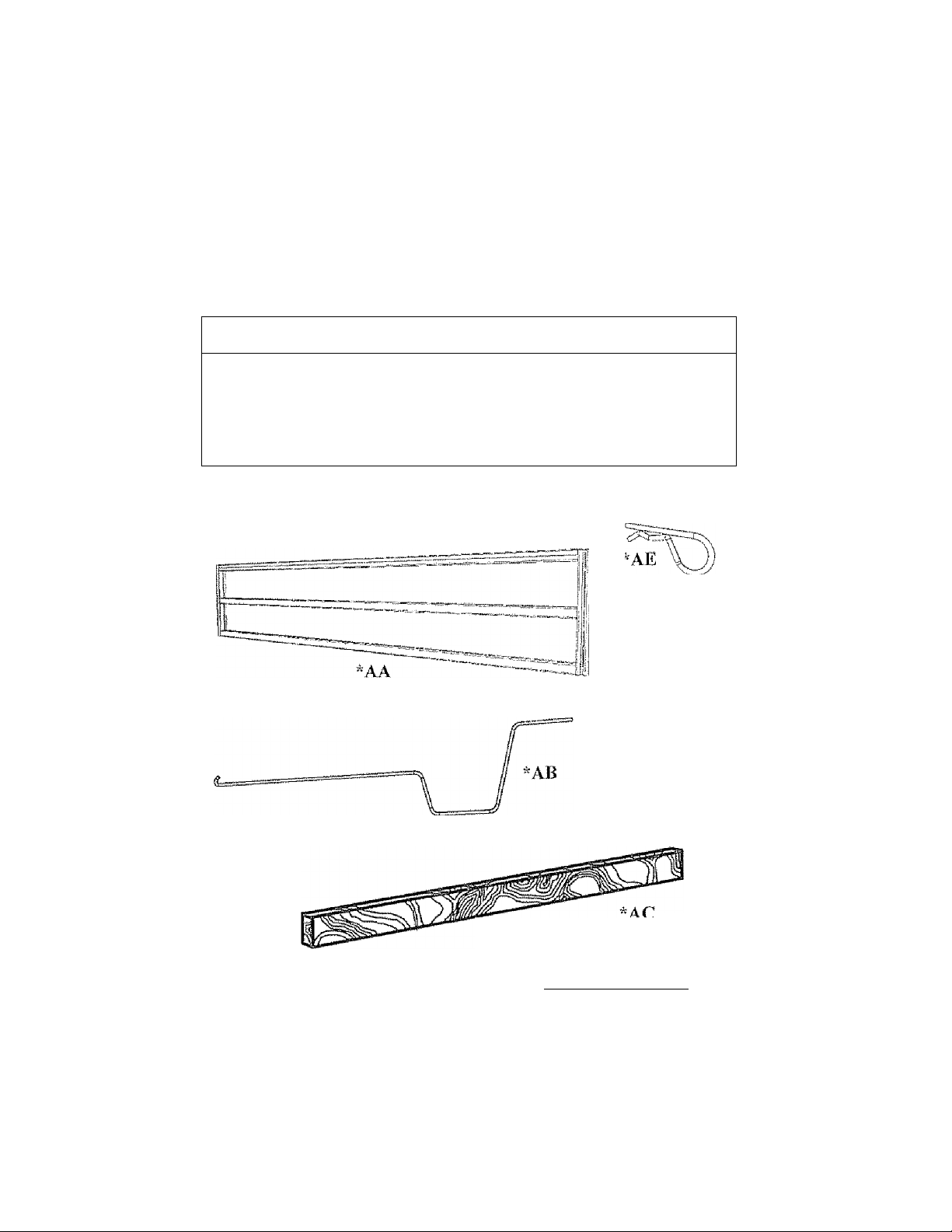
PARTS LIST
ID
ЛЛ
AB Hand Crank 1
ЛС
AD
\AE
Description Qty
Oiitc/R-UTHp -2.
T X 4” Distance Indicator (Do Not Discard) I
L ocking Pin w/ Lanyard (Connected) 1
CoU c г Key (Con ri ec! cd) 1
HARDWARE IDENTIFIER
(*Nol to Scale)
'AD
.....
tJV
V
□
□
□
□
□ 1
Oo Not Discard
TOOLS HEEDED (NOT INCLUDED)
13/16” Lug Wrench or Tire Iron (For changing Tires and periodic lighicning of L ug
, Nuts)
11
Page 12
SECTION 3i
.............
FIRST-TIME SET-UP REQUIREMENTS
Lug Nuts: Tightening Sequence, Torque Requirements
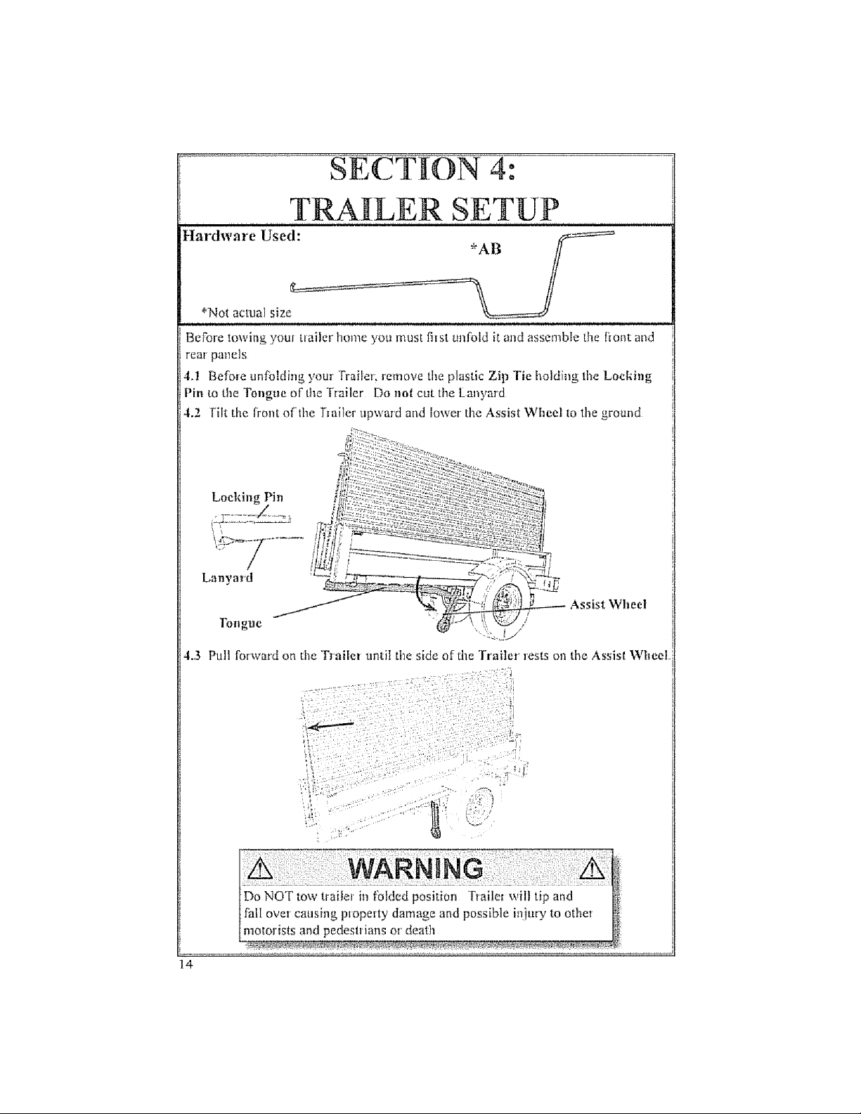
• Before unfbiding your Trisiler. remove the plastic Zip Tic holding the Locking Pin
to the Tongue of the Fraiter Do not cut the Lanyard ,j._
-------------
^Locking Pin
~~———— Lanyard
A
Lag nuts arc prone to [ooseti after initial inslailaiion possibly castsing
ilic wheel So separate iVom the trailer leading to property duniage, death
or serious iitjury
• Check lug nuts for iiglitness on a new trailer or when M'liecifs) have
been remoumed after the (irsi 10, 25 and 5(1 miles of di iving and
after any insptsci
• Lug nuts for the tires must be lighiened by the user betbre each use
• Scars cattnoS be heid responsible for damages caused by loosened
lug nuts
• Before towing the Trailer, you must cnsuie the lug nuts are tightened to the pioper
torque
• The torque requirements for the Lug Nuts are 95 - 120 ft/lb. Do not exceed 120
ft/Ib of torque Tighten the Lug Nuts in the sequence below before you leave the
dealer
Tifiliien lug nuts
in the following
order;
WARNING
^
............
.........................................................................................................
A
.........
r
Verily the proper PSl for your tire
• Tire pressure for the 12” t im & tire should be at 80 psi
Follow posted speed limits but do not exceed 65 mpli.
A
Before loading Trailer, Trailer must be properly connected to
the Tow Vehicle to stabilize the Trailer Failure to follow this
warning could result in property damage, personal itijuty and
death. _
12
WARNING
A
Page 13
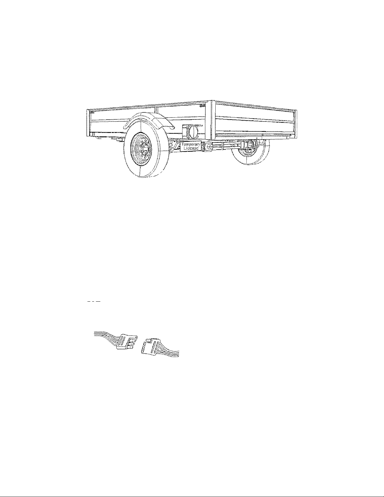
Connecting Temporary License Plate
Jf your slate requires a temporary license on your trailer, secure the license to the
license plate holder located on the left blinker before lowing your trailer home
Note; Before leaving the dealet, ensure you have the Manufacture!s Certificate of
Origin (Tiiie) signed over to you
Note: For all inquiries regarding trailer title and registration, please contact your
local Department of Motor Vehicles (DMV) os your local county tax assessor’s
oflice.
Connecting the Electrical Cables
Connect the bailer lights to the tow vehicle’s electrical system using the
electrical connectors
• Check all lights for proper operation
1 Clearance and Running Lights {Turn on tow vehicle headlights)
2 Brake Lights (Step on tow vehicle brake pedal)
3 Turn Signals (Operate tow vehicle direciionai signal lever)
/L Warning: To ensure your trailer lights function properly, firmly insert the
¿---A Plug (Trailer) into the Receptor (Tovv Vehieic)
Note: Jf your connector does nor look like the one pictuied. you need to purchase
on adapter.
From Trailer From Tow Vehicle From Trailer From Tow Vehicle
Note: Please read Sections 4 and 5 for additional infbmiation on deploying,
coupling and towing your trailer
A
Do'noTlrfi~sporrpeoptTTiT llw’lTalieF'FaF!^^^
rng could result in serious injury such as broken bones, brain
dama'ic, naraivsis oi death
WARNING
A
Page 14
Page 15
Wilh the right side of the Trailer resting on the Assist Wheel, you can now unfold the
Trailer,
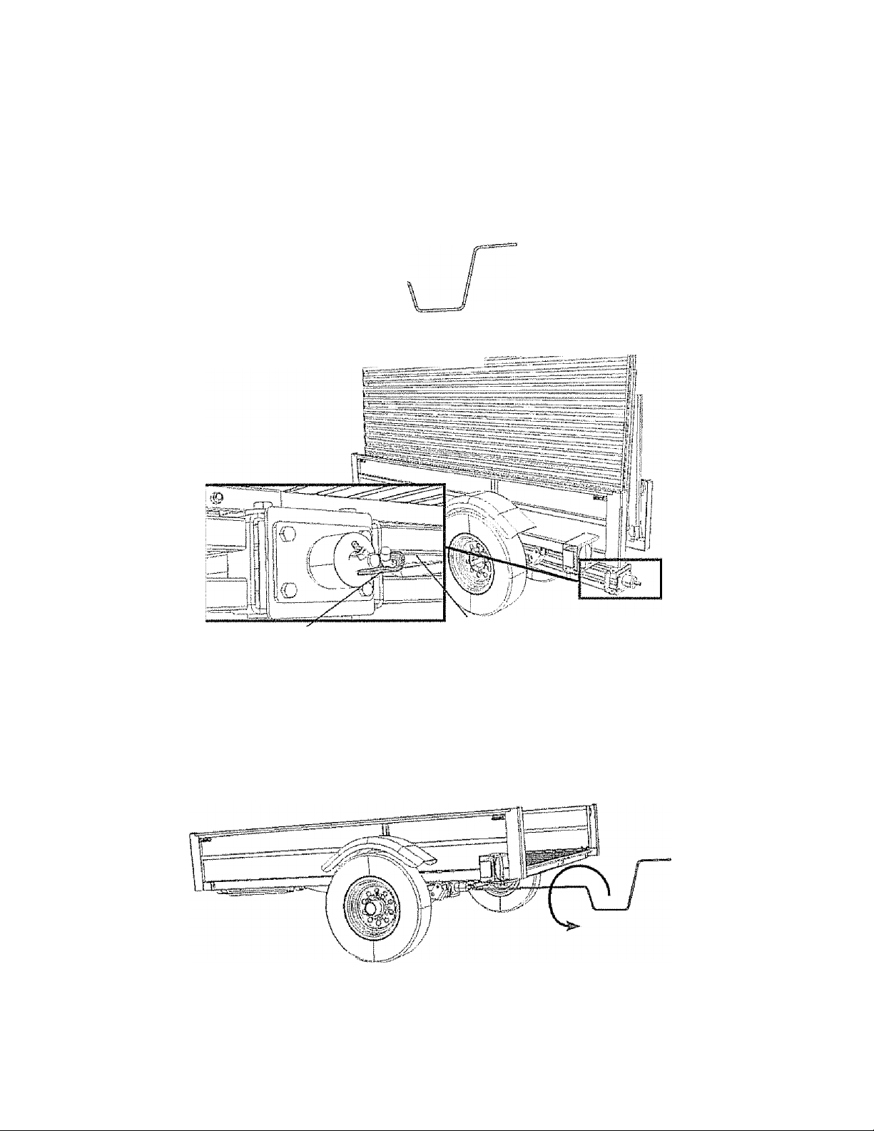
4.4 Remove the Hand Crank (AB) ftom the clips just imside wall of the Trailer,
Note: You may need to remove the Gate/Ramp to access the Hand Crank from the
insde wall of the Trailer
4.5 insert the Hisnd Crank into the jack’s Hand Cr ank Coupler Plate at the rear of
the Trailer (as shown).
Hand Crank Coupler Plate
A
Watch lor pinch points while folding artd deploying trailer as
serious injury could occur.
4.6 Turn the Hand Crank counter-clockwise to unfold the Trailer Continue
turning the Hand Crank until you cannot turn it any fiifther
WARNING
Hand Crank
A
15
Page 16
16
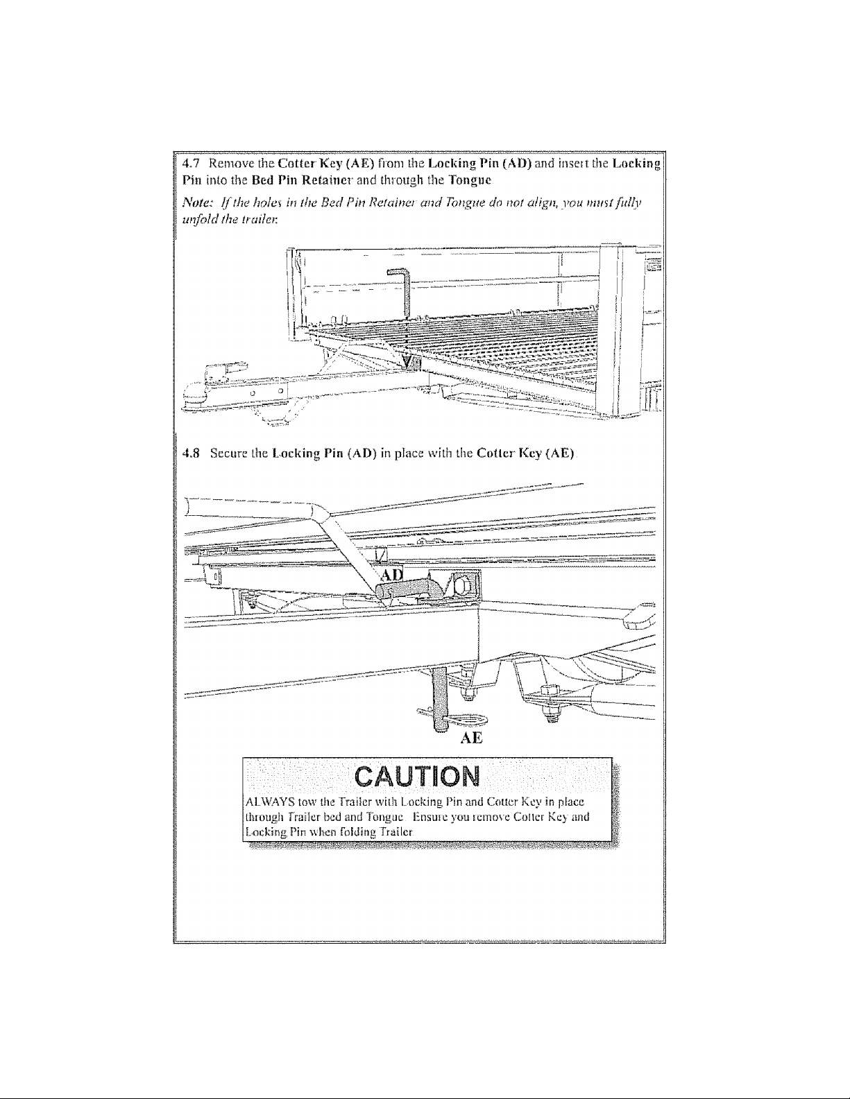
Page 17
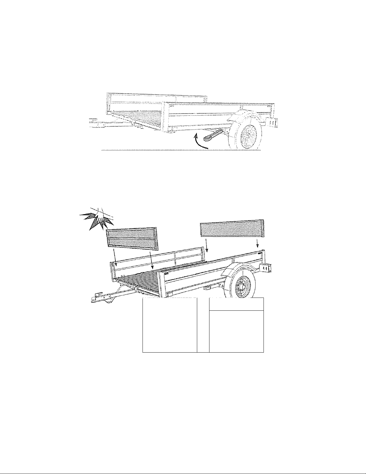
43 After unfolding the Ttailer, lift up on the fi'ont of the Trailer and reliact the Assist
Wheel
CAUTION
ALWAYS load and tow the Trailer while the Assist Wheel is up Failure
10 heed this warning could result hi permaneni damage to iltc Assist
Wheel and void warranty.
4.10 Insert the Front and Rear Gates (AA) in place Both Gates are the .same; you
can insert each in either the front or tear position
/|\ WARNING: Watch for pinch points as serious injury could
'^^occur;
4,11 Press down firmly
on the Gates until they
lock into place under the
Lip.s of the Side Panels
A WARNING
Do NOT use the Gates for lie-down locations Al! articles being
towed must be tied to the side wails of the Frailer, Gates can
dislodge causing properly damage and possible injuty or death to
other motorists and pedestrians
■'^1
' ' i
—
-- T'
i 1 1 ip " ' ‘
________
A
17
Page 18

4.12 Use the Front and Rear Gates as ramps Simply lemove each Gate and place
the ends into the channel at the rear of the Trailer Bed i
I
A WARNING
Only load Trailer while it is connected to the Tow Vehicle or
Trailer could tip causing property damage, possible injury or
death
4.13 When driving vehicles such as ATVs up the ramps, first place the 2” x 4” x 63”
Distance Indicator in the grooves of the side panels where the front gate should go to 1
help you avoid cliiving too fer |
A
The 2” % 4” Distance Indicator will xjoEprevetU}'ou From driving
off the Fiont of the Trailer It is Used to let you know you’re going
loo Fat Drive slowly and cautiously when driving vehicles up
the ramps.
CAUTION A
2” X 4” X 63” Distance Indicator
' Do Not Discard
A
I
Note: To fold the TraHer, simply i emove the Locking Pin and Gaia and turn the
Htmd Crmik dockwhe Store the Gates and Hand Crank in the Trailer.
A
|Do not transport people in the trailer Failure to heed this warn-
tng could result in serious tujsrry such as broken bones, brain
damage, paralysis or death
18
WARNING A
Page 19

ECTION 5: COUPLING TO
.1 MJLMIj 1 V./ У T V 1 i ж 11V-' KjMb
1?
ATTACHING THE TRAILER TO TOW VEHICLE
Yoti must foJIow ali оГ tlie safety precautions and instructions in this manual lo
ensure safety of persons, cargo, and satisfactory' life of the trailer.
5.1 Warning: Using an Adequate Tow Vehicle and Hitch A
If the vehicle or hitch is not property selected and matched lo the Gross Vehicle
Weight Rating (GVWR) of your trailer; you can cause an accident that could lead to
death or serious injuiy If you already have a tow vehicle, know your velticle tow
rating and make certain tire trailer's rated capacity is less than or equal to the tow
vehicle's rated lowing capacity. If you already have (or plan to buy) a trailer, make
certain that the tow rating of the tow vehicle is equal to or greater than that of the
trailer
5.2 Warning: Coupling and Uncoupling the Trailer A
A secure coupling (or fastening) of the trailer to the tow vehicle is essential, A loss
of coupling may result in death or serious injury. Therefore, you must understand
and follow all of the instructions for coupling your trailer to your tow vehicle.
The following parts are involved in ensuring a secure coupling between the trailer
and tow vehicle:
Coupler: A device on the longue of the trailer that connects to the hitch on the
tow vehicle.
Hitch: A device on the low vehicle that supports the weight of the trailer tongue
and pulls the trailer. The coupler attaches to the hitch,,
Safety chains: If the coupler connection comes loose, the safety chains can keep
the trailer attached to the tow vehicle. With properly rigged safety chains, it is
possible to keep the tongue of the trailer frotn digging into the road pavement,
even if the coupler-to-hitch connection comes apart.
Trailer lighting (and braiung) connector: A device that connects electrical
power from the tow vehicle to the trailer. Electricity is used to turn on brake
lights, running lights, and turn signals as required.
5.2.1 Trailer with Bail-Hilch Coupler
A ball hitch coupler connects to a ball that is located on or under the rear bumper
of the tow vehicle. This system of coupling a trailer to a tow vehicle is sometimes
refeired to as “bumper pull.”
Warning: We have utilized a 2-inch Ball Hitch coupler that is suitable for the
size and weight of the trailer: You must provide a hitch and .2-inch ball for
your tow vehicle, where the load rating of the hitch and ball is equal to or greater
19
Page 20

than that ofyoiir trailer. Also, the ball size must be the same as the coupler size. If
the hitch ball is too small, too large, is underrated, is loose or is worn, the trailer can
come loose from the tow vehicle, and may cause death or serious injury,
THE TOW VEHICLE, HITCH AND BALL MUST HAVE A RATED TOWING
CAPACITY EQUAL TO OR GREATER THAN THE TRAILER GROSS
VEHICLE WEiGHT RATING (GVWR).
IT IS ESSENTIAL THAT THE HITCH BALL. BE OF THE SAME SIZE AS THE
COUPLER (2 INCHES),
The ball size and load rating (capacity) are marked on the ball; hitch capacity is
marked on the hitch
S 2.T. 1 Before coupling the trailer to the tow vehicle
• Ensure the size and rating of hitch ball match the 2-inch coupler on your trailer.
Hitch balls and couplers are marked with their size and rating
■ Wipe the hitch ball clean, inspect it visually and feel fot flat spots, cracks Emd
pits,
• Rock the bail to make .sure it is tight to the bitch, and visually check that the
hitch ball nut is solid against the lock washer and hitch frame
• Wipe the inside and outside of the coupler clean and inspect it visually foi'cracks
and deformations; feel the inside of the coupler for worn spots and pits,
» Be sure the coupler is tight to the tongue of the trailer. All coupler fasteners
must be visibly solid against the trailer ftame.
• Raise the bottom surface of the coupler above the top of the hitch ball Use
wood or concrete blocks to support the trailer longue.
S.2.1.2 Preparing the coupler and hitch
• Lubricate the hitch bail and the inside of the coupler with a thin layer' of
automotive bearing grease.
• Open the coupler locking mechanism, Bali couplers have a locking mechanism
with an internal moving piece and an outside handle
In the open position, the coupler is able to drop fully onto the hitch bail.
See “Uncoupling the Trailer” for details on placing the coupler in the “open”
position,
' Slowly back up the tow vehicle so that the hitch ball is near or aligned under the
coupler,
5,2*13 Coupling the trailer to the tow vehicle
Lift the couplet and place it over the ball
• Lower the trailer until the coupler fully engages the hitch ball.. If the coupler
does not line up with the hitch ball, adjust the position of the tow vehicle,.
' Engage the coupler locking mechanism In the engaged position, the locking
mechanism securely holds the coupler to the hitch ball,
20
Page 21

• Insert a pin or lock through the hole in the locking mechanism
• Ensure tl5e coupler is all the way on the hitch ball and the locking mechanism is
engaged
• Lower the trailer so that its entire tongue weight is held by the hitch Push the
safety latch downward to a horizontal position to lock it in place
• Pull up on the coupler to ensure it is securely fastened to the tow vehicle
if the coupler cannot be secured to the bitch ball, do not fow the traiien
Refer to Section 10.2.3 for information on coupling your trailer.
i ^ ■
A WARNING
Use 3ÖW Motor Oil to lubricate the ball and inside of coupler
Always check ball and coupler before each low for damaged O)
worn edges Damaged baits and couplers should be replaced
immediately Failure to follow this warning could result in
property damage, personal injury and death
5.2.L4 Rigging the safety chains
• Visually inspect the safety chains and hooks for wear or damage Replace worn
or damaged safety chains and hooks before towing
* Rig the safely chains so that they:
1 cross underneath the coupler;
2 loop around a frame member of the tow vehicle or to holes provided in the
hitch system (but, do not attach them to an interchangeable pari of tire hitch
assembly); and
3 have enough slack to permit tight turns, but not be close to the- load surface,
so if the trailer uncouples, the safety' chaiii.s can hold the tongue up above the
road.
A
Page 22

WARNING
improper rigging of the safety chains can result in loss of control
of the trailer and the tow vehicle, leading to death or serious
injtity, if the trailer uncouples from the tow vehicle
■ Fasten chains to frame of tow vehicle Do not fasten chains
to any part of the hitch unless the hitch has holes or loops
specifically for that purpose
' Cross chains underneath hitch and coupler with enough, slack
to permit turning, and to hold tongue up, if the trailer comes
loose
5.2.1.5 Connecting the ciectrical cables
Connect the trailer lights to the tow vehicle's electrical system using the electrical
connectots
• Check all lights for proper operation
1 Clearance and Running Lights {Гшп on tow vehicle headlights)
2, Brake L ights (Step on low vehicle brake pedal)
3 Turn Signals (Operate tow vehicle directional signal lever)
Warming: To ensure your trailer hghls function properly, firmly insert the
A
Ping (Trailer) into the Receptor (Tow Vehicle)
Follow posted speed limits but do not exceed 65 mph
A
22
A WARNING
IDo not transport people in the trailer. Failure to heed this warn- Ч
png could result in serious injury such as broken bones, brain
damage, paialysis or deaiii
A
Í!
i- ,
Page 23

Noie: if your connector doe'; not look /ike the one pictured you need to purchme
an adapter.
From Trailer
From Trailer
A
Check the connection periodicaliy to ensure tail and break lights
ftmetion prooerlv Faiitire lo fbllaw this wanting could result in
property damage, personal itijury and death
5.2,T6 Uncoupling the Trailer
Follow these steps to uncouple your ball hitch trailer from tlie tow vehicle:
1 Remove Uie load fiom the trailet
2 Block trailer tires to prevent the trailer from rolling
.3. Place wood or concrete blocks under the coupler for support.
4, Disconnect the electrical connector
5, Disconnect the safety chains from the low vehicle
6, Unlock the coupler and pull the safety latch upward to a vertical position aiid
lift tlie trailer off the ball
WARNING
From Tow Vehicle
From Tow Vehicle
A
Unlock
23
Page 24

SECTION TIME Si SAFETY
INFORMATION
CHECMNG & CHANGING TIRES
6.1 Defermiiiing Correct Load Limit “Trailer
6.i.l Trailers 10,000 Pounds GVWR or Less
1 Locale the statement, “Hie weight of cargo should never exceed XXX kg or
XXX ibon your vehicle’s placard.
2 This figure equals the available amount of cargo and luggage load capacity.
3 Determine the combined weight of luggage and cargo being loaded on the
vehicle. That weight may not safely exceed the available cargo and luggage load
capacity,
The trailer’s placard refers to the Tire Information Placard attached adjacent to or
near the trailer’s VIN (Certification) label at the left front of the trailer
6.2 Determining Correct Load Limit“ Tow Vehicle
1. Locate the statement, ‘The combined sveight of occupants and cargo should
never exceed XXX lb on your vehicle’s placard
2. Determine the combined weight of the driver and passengers who will be riding
in your vehicle
3. Subtract the combined weight of the driver and passengers from XXX kilograms
or XXX pounds.
4. The resulting figure equals the available amount of cargo and luggage capacity
For example, if the “XXX” amount equals 1400 lb and there will be five 150 !b
: passengers in your vehicle, the amount of available cargo and luggage capacity is
: 650 lb (1400-750 (5 x ISO) - 650 lb.),.
5. Determine the combined weight of luggage and cargo being loaded on the
; vehicle That weight may not safely exceed the available cargo and luggage capacity
calculated in Step # 4,
; 6, If your vehicle will be towing a trailer, load from your trailer will be transferred
: to your vehicle Consult the tow vehicle’s manual to determine how this weight
■ transfer reduces the available cargo and luggage capacity of your vehicle.
6.3 Glossary of Tire Terminology
: Accessory weight: The combined weight (in excess of those standard items which
^ may be replaced) of automatic transmission, power steering, power brakes, power
windows, power seats, radio and heater, to the extent that these items are available
; as factory-installed equipment (whether installed or not).
Bead: The part of the lire that is made of steel wires, wrapped or reinforced by ply
: cords and that is shaped to fit the i sm
Bead separation: This is the breakdown of the bond between components in the
' bead.
: Bias ply tire: A pneumatic lire in which the ply cords that extend to the beads are
^ laid at alternate angles substatilially less than 90 degrees to the center line of the
tread.
24
Page 25

Carcass: The tire structure, except treacTand sidewaii rubber wlticb, when inflated,
bears the load.
Chunking: The breaking away of pieces of the tread or sidewall
Cold itifialion prcs.sure: The pressure in the lire before you drive
Cord; The strands forming the plies in the tire
Cord separation: The parting of cords from adjacent rubber compounds
Cracking: Any parting within the tread, sidewall, or inner liner of the tire
extending to cord material,.
CT: A pneumatic tire witli an inverted flange lire and rim system in which the i im
is designed with rim flanges pointed radially inward and the tire is designed to fit
on die underside of the rim in a manner that encloses the rim flanges inside the air
cavity of the tire,.
Curb weight: The weight of a motor vehicle with standard equipment including
the maximum capacity of fuel, oil, and coolant, and, if so equipped, air conditioning
and additional weight optional engine
Extra load tire: A tire designed to operate at higher toads and at higher inflation
pressures than the corresponding standard tire.
Groove: The space between two adjacent tread ribs.
Inner liner: The layer(s) forming the inside surface of a tubeless tire that contains
the inflating medium within the tire
Inner-liner Separation: The parting of the inner liner from cord material in the
carcass.
Intended outboard sidewall The sidewall that contains a white-wall, bears white
lettering or beats manufacturer, brand, and/or model name molding that is higher or
deeper' than the same molding on the other sidewall of the lire or the outward facing
sidew'all of an asymmetrical tire that has a particular side that must always face
outward when mounted on a vehicle.
Light truck (LT) tire: A tire designated by its manufacturer as primarily intended
for use on lightweight itudes or multipurpose passenger vehicles.
Load rating: The maximum load that a lire is rated to carry for a given inflation
pressure.
Maximum load rating: The load rating for a tire at the maximum peimisstble
inflation pressure for that tire
Maximum permissible inflation pi es.sure: The maximum cold inflaiioii pressure
to which a tire may be inflated
Maxirrtum loaded vehicle weight: The sum of curb weight, accessory weight,
vehicle capacity weight, and production options weight.
Measuring rim: The rim on which a tire is fitted for plwsical dimension
requirements.
Non-pneumatic rim: A mechanical device which, when a non-pneumatic tire
assembly incorporates a wheel, supports the tire, and attaches, either integrally or
separably, to the wheel center member and upon which the tire is attached,.
Non-pneumatic spare tire assembly: A non-pneumatic tire assembly intended
for temporary use in place of one of the pneumatic tires and rims that are fitted to a
passenger car in compliance with the requirements of this standard.
Non-pneumatic tire: A mechanical device which transmits, either directly or
through a wheel or wheel center member, the vertical load and tractive forces from
25
Page 26

the roadway to the vehicle, generates the tractive forces that provide the directional
control of the vehicle and does not rely on the containiTtent of any gas or fluid for
providing those functions.
Non-pneumatic tire assembly: A non-pneumatic tire, alone or in combination with
a wheel or wheel center member, which can be mounted on a vehicle.
Normal occupant weight: This means 68 kilograms (150 lb.) times the number of
occupants specified in tire second column of Table 1 of 49 CFR 57 L. 110
Occupant distribution: The distribution of occupants irs a vehicle as specified in
the third column of Table 1 of 49 CFR 571.110.
Open splice: Any parting at any junction of tread, sidewall, or inner liner that
extends to cord material.
Outer diameter: The overall diameter of an inflated new lire
Overall width: The linear distance between the exteriors of the sidewalls of an
inflated tire, including elevations due to labeling, decorations, or pi elective bands or
ribs.
Ply; A layer of rubber-coated parallel cords..
Ply separation: A parting of rubber compound between adjacent plies
Pneumatic tire: A mechanical device made of rubber, chemicals, fabric and
steel or other materials, that, when mounted on an automotive wheel, provides the
traction and contains the gas or fluid that sustains the load
Production options weight: The combined weight of those installed regular
production options w-eighing over 2.3 Idlogtams (5 Ib) in excess of those standard
items which they replace, not previously considered in curb weight or accessory
weight, including heavy duty brakes, ride levelers, roof rack, heavy duty battery,
and special irini.
Radial ply tire: A pneumatic tire in which the ply cords that extend to the beads
are laid at substantially 90 degrees to the center line of the tread
Recommended inflation pressure; This is the inflation pressure provided by lire
vehicle manufacturer on the fire information label and on the Certification / VIN
tag.
Reinforced tire: A tire designed to Operate at higlier loads and at higher inflation
pressures than the corresponding standard tire
Rim: A metal support for a tire or a tire and tube assembly upon which the tire
beads are seated.
Rim diameter: This means the nominal diameter of the bead seat
Rim size designation: This means the rim diameter and width.
Rim type designation: This means the industry of manufacturer’s designation for
a rim by style Of code
Rim width; This means the nominal distance between rim flanges
Section width: The linear distance between the exteriors of the sidewalls of art
inflated tire, excluding elevations due lo labeling, decoraiiott, or protective bauds.
Sidewall: That portion of a tire betw'cen the tread and bead.
Sidewall separation: The parting of the rubber compound from the cord material
in the sidewall.
Special Trailer (ST) tire: The “ST’ is an indication the tire is for irailer use only,
Test rim: The rim on which a tire is fitted For testing, and may be any rtin listed as
26
Page 27

appropriate for use with that tire.
Tread: That portion of a tire that comes into contact with the road.
Tread rib: Л tread section running circumferentialiy around a tire.
Tread separation: Pulling away of the tread from the tire carcass.
Tread-wear indicators (TWI): The projectiorts within the principal grooves
designed to give a visual indication of the degrees of wear of the tread.
Vehicle capacity weight: The rated cargo and luggage load plus 68 kilograms (150
!b.) times the vehicle’s designated seating capacity'
Vehicle maximum load on the tire; The load on an individual tire that is
determined by distributing to each axle its share of the maximum loaded vehicle
weight and dividing by two
Vehicle norma! load on the tire; The load on an individual tire that is determined
by distributing to each axle its share of the curb weight, accessory weight, and
normal occupant weight (distributed in accordance with Table Í of CRF 49 571,110)
and dividing by .2.
Weather side: The surface area of the rim not. covered by the inflated tire
Wlieei center member: In the case of a non-pneumatic tire assembly incorporating
a wheel, a mechanical device which attaches, either integrally or separably, to the
non-pneumatic rim and provides the connection between the non-pneumatic rim
and the vehicle; or, in the case of a non-pneumatic tire assembly not incorporating
a wheel, a mechanical device which attaches, either mlegrally or separably, to the
non-pneumatic tire and provides the connection between tire and the vehicle
Wheel-hoi ding fixture: fire fixture used to liold the wheel and tire assembly
securely during testing.
6.4 Tire Safety - Everything Rides on It
The National Traffic Safety Administration (NHTSA) has published a brochure (DOT
HS 809 361) that discusses all aspects of Tire Safely, as required by CFR 575,6.
This brochure is reproduced in part below. It can be obtained and downloaded ftora
NHTSA, free of charge, from the following web site:
hrtp;//www.nhtsa.dol.gov/cars/raIes/TireSafety/ridesonil/tires_mdex hlml
Studies of tire safety show that maintaining proper tire pressure, observing tire
and vehicle load limits (not carrying more weight in your vehicle than your tires
or vehicle can safely handle), avoiding road hazards, and inspecting tires for cuts,
slashes, and other irregularities are the most important things you can do to avoid
lire failure, such as tread separation or blowout and flat tires These actions, along
with other care and maintenance activities, can also:
• Improve vehicle handling
• Help protect you and others from avoidable breakdowns and accidents
• Improve fuel economy
• increase the life of your lites.
This booklet presents a comprehensive overview of tire safely, including
infotmation on the following topics:
• Basic tire maintenance
27
Page 28

' Uniform Tire Quality Grading System
' Fundamental characteristics of tires
• Tire safety tips .
Use this information to make tire safety a regular part of your vehicle maintenance
routine. Recognize that the time you spend is minima! compared with the
inconvenience and safety consequences of a flat tire or otlter tire failure
6.4.1 Safetj' firsi“Basic tire maintenance
Properly maintained tires improve the steering, stopping, traction, and loadcariying capability of your vehicle Under-inflated tires and overloaded vehicles
are a major cause of tire failure Therefore, as mentioned above, to avoid flat tires
and other types of tire failure, you should maintain proper tire pressure, observe
tire and vehicle load limits, avoid road hazards, and reguiarly inspect your tires
6.4.2 Finding yorir vehicle’s recommended tire pressure and load limits
Tire information placards and vehicle certification labels contain information on
tire.s and load limits, These labels indicate the vehicle manufacturer’s information
including:
• Recommended tire size
• Recommended tire inflation pressure
• Vehicle capacity weight (VCW-the maximum occupant and cargo weight a
vehicle is designed to cairy)
• Front and rear gross axle weight ratings (GAWR- the maximum weight the
axle systems are designed to cany).
Both placards and certification labels are permanently attached to the trailer near”
the left ftont,
6.4.3 Understanding tire pressure and load limits
Tire inflation pressure is the level of air in the tire that provides it with load
carrying capacity and affects the overall performance of the vehicle. The tire
inflation pressure is a number that indicates the amount of air pressure- measured
in pounds per square inch (psif-a tire requires to be properly inflated (You will
also find this number on the vehicle information placard expressed in kilopascals
(kPa), which is the metric measure used iriternationaliy,)
Manufacturers of passenger vehicles and light trucks determine this number
based on the vehicle’s design load limit, that is, the greatest amount of weight a
vehicle can safely catty and tire vehicle’s tire size T!ie proper tire pressure for
your vehicle is referred to as the “recommended cold inflation pressure ” (As you
will read below, it i.s difficult to obtain the tecommended lire pressure if your dies
are not cold,)
Because tires are designed to be used on more than one type of vehicle, tire
manufacturers list the ‘'maximtim permissible inflation pressure” on the tire
sidewall. This number is the greatest amount of air pressure that should ever be
put in the tire under normal driving conditions.
28
Page 29

6.4.4 Checking tire pres.sure
it is important to dieck your vehicle’s tire pressure at least once a month for the
following reasons:
• Most tires may natutally lose air overtime.
• Tires can lose air suddenly if you drive over a pothole or other object or if you
strike the curb when parking,
• With radial tires, it is usually not possible to determine under-inflation by visucsl
inspection.
For convenience, purchase a tire pressure gauge to keep in your vehicle. Gauges
can be purchased at tire dealerships, auto supply stores, and other retail outiels,.
The recommetided tire inflation pressure that vehicle raariufaciurers provide
reflects the proper psi when a lire is cold The term cold does not relate to tlte
outside temperature. Rather, a cold tire is one that has not been driven on for at
least three hours. When you drive, your tires get warmer, causing the air pressure
within them to increase. Therefore, to get an accurate tire pre.ssure reading, you
must measure tire pressure when the tires are cold or compensate for the extra
pressure in warm tires
6.4.5 Steps for maintaining proper tire pressure
• Step 1: Locate the recommended tire pressure on the vehicle’s tire information
placard, certification label, or in tile owner’s manual
• Step 2: Record the tire pressure of all tires
• Step 3; If the tire pres.sure is too high in any of the tires, slowly release air by
gently pressing on the tire valve stem wdth the edge of your tire gauge until you
get to the correct pressure.,
■ Step 4: If the tire pressure is too low, note the difference between the measured
tire pressure and the correct tire pressure. These “missing” pounds of pressure are
what you will need to add.
• Step 5; At a service station, add the missing pounds of air pressure to each tire
that is under-inflated
• Step 6: Check all the tires to make sure they have the same air pressure (except
in cases in which the front and rear tires are suppo.sed to have differetit amounts of
pressure).
If you have been driving your vehicle and think that a trailer tire is under-ínflated,
fit! it to the recommended cold inflation pressure indicated on your vehicle’s tire
information placard or certification label While your tire may still be .slightly
under-inflated due to the extra pounds of pressure in the warm tire, it is safer
to drive with air pressure that is slightly lower than the vehicle manufacturer’s
recommended cold inflation pressure than to drive with a significantly under
inflated tire Since this is a temporary fix, don’t forget to redieck and adjust the
tire’s pressure svhen you can obtain a cold reading
6.4.6 Tire size
To maintain tire safety, purchase new tires that are the same size as the vehicle’s
oiiginal tires Or another size recommended by the mamifacturer. Look at the
tire information placard, the owner’s manual, or the sidewall of the tire you are
29
Page 30

replacing to find this information If you have any doubt about tlic correct size to
choose, consult with the tire dealer
6.4.7 Tire tread
The tire tread provides the gripping action and traction that prevent your vehicle
from slipping or sliding, especially when the road is wet or icy, In general, tires
are not safe and should be replaced when the tread is worn down to 1/16 of an
inch, Tires have built-in tread-wear indicators that let you know when it is time
to replace your tires. These indicators are raised sections spaced intermittently in
the bottom of the tread grooves. When they appear ‘tovsn” with the outside of the
tread, it is lime to replace your tires.. Another method for checking tread depth is
to place a penny in the tread with Lincoln’s head upside down and facing you. If
you can see the top of Lincoln’s head, you are ready for new tires
6.4.8 Tire balance and wheel alignment
To avoid vibration or shaking of the vehicle when a tire rotates, the tire must be
properly balanced. This balance is achieved by positioning weights on the wheel
to counterbalance heavy spots on the wheel-and-tire assembly. A wheel alignment
adjusts the angles of the wheels so that they are positioned correctly relative
to the vehicle’s frame,. This adjustment maximizes the life of your tires. These
adjustroents require special equipment and should be performed by a qualified
technician,
6.4.9 Tire repair
The proper repair ofb, punctured tire requires a plug for the hole and a patch for
the area inside the tire that surrounds the puncture hole, Punctures through the
tread can be repaired if they are not too large, but punctures to the sidewall should
not be repaired. Tires must be removed from the rim to be properly inspected
before being plugged and patched,
6.4.t0 Tire Fundamentals
Federal law requires tire manufacturers to place standardized information on the
sidewall of all tires This information identifies and describes the frmdamental
characteristics of the lire and also provides a tire identification miniber for safety
standard certification and in case of a геенН
6.4.10.1 Information on Passenger Vehicle Tires
Please refer to the diagram on the next page.
30
Page 31

Raiio of iicighs U> \
H'idlli (aspect ratio)
Nomina! widtli of
¡ire in njidimctcre
Passenger
car lire
Rim tliamcfcr
code
symboJ
IJ,S, DOT tire
itlcniificiiiiim tuimbci
Sever snow
conditions
Mas ^
pcrmissflblc
ihllattun
pressure
Treadwtar, traefnm
and lenipcralurc grades
Max. inad rating
Tire ply
composition
and ma (cria ts
used
P; The “P” indicates the lire is for passenger vehicles.
Next number; This three-digit number gives the width in mtlUmeters of the tire
fi'om sidewall edge to sidewall edge, In general, the larger the number, the wider
the tire..
Next number: This two-digit number, knowm as the aspect ratio, gives the tire’s
ratio of height to width Numbers of 70 or lower radicate a short sidewall for
improved steering response and better overali handling on dry pavement.
R: The “R” stands for radial, Radial ply construction of tires has been the industry
standard for the past 20 years.
Next number: This two-digit number is the wheel or rim diameter in inches If
you change your wheel size, you will have to purchase new tires to match the new
wheel diameter.
Next number: This two- or three-digit number is the the’s load index. It is
a measurement of hoxv much weight each tire can support You may find this
ittfonriation in your owner’s manual If not, contact a local tire dealer: Note: You
mas? not find this infonnation on all liies because it is not required by law,
M+S: The “M+S” or “M/S” indicates that the lire has some mud and snow
capability Most radial tires have these markings; hence, they have some mud and
snow capability
Speed Rating: The speed rating denotes the speed at which a tire is designed to be
driven for extended periods of time. The ratings range from 99 miles per hour
fmph) to 186 mph Note: You may not find this information on all tires because it is
not required by law.
* For tires with a maximum speed capability over 149 mph, lire manufacturers
sometimes use the letters ZR. For those with a maximum speed capability over 186
mph, tire manufacturers always use the letters ZR,
U.S. DOT Tire Identification Number
This begins with the letters “DOT” and indicates that the tire meets all
31
Page 32

federal standards, The next hvo numbers or letters are the plant code where it was
manufactured, and the last four numbers represent the week and year the tire was
built. For example, the numbers 3197 means the 31 st week of 1997- The other
numbers are marketing codes used at the manufacturer’s discretion. This
information is used to contact consumers ifa tire defect requires a recall
Tire Ply Composition and Materials Used
The number of plies indicates the number of layers of rubber-coated fabric in the
tire. In general, the greater the number of pHes, the more weiglit a tire can support
Tire manufacturers also must indicate the materials in the tire, which include steel,
nylon, polyester, and others,
MaxiiiHun Load Rating; This number indicates the maximum load in kilograms
and pounds that can be carried by the tire,
Maxinxusn Permissible Inflation Pressure: This number is the greatest amount
of air pressure iliat should ever be pul in the tire under nonnal driving conditions
6.4J0.2 UTQGS Information
Tread-wear Number: This number indicates the tire’s wear rate. The highet' the
tread-wear number is, the longer it should take for the tread to wear down. For
example, a tire graded 400 should last twice as long as a tire graded ,200
Traction Letter: This fetter indicates a tire’s ability to stop on wet pavement, A
higher graded tire should allow you to stop your car on wet roads in a shorter
distance than a tire with a lower grade Traction is graded from highest to lowest as
“AA’V’A”, “B”, and “C”
Temperature Letter: This tetter indicates a tire’s resistance to heat The
temperature grade is for a tire that is inflated properly and not over loaded
Excessive speed, under inflation or excessive loading, either separately or in
combination, can cause heat build-up and possible tire failure. From highest to
lowest, a tire’s resistance to heat is graded as “A”, “B”, or “C”.
6,4.10.3. Additional Information on Light Truck Tires
Please refer to the following diagram:
Load
l ight truck lire
Maxifflifm load
& hiüalîon when
used a.s a single
32
Load inltiition
limits
Mtiximura iond
iniiaiion when
iiscif iw a dual
Severe .snow
conditions
Page 33

Tires for light tracks have other markings besides tlsose found on the sidewails of
passenger tires
LT; The‘T Г” indicates the tire is For light trucks ш trailers
ST: An “ST" is an indication the lire is for traiicr use only.
Max. Load Dual kg (lb) at kPa (psi) Cold: This inlbi raaiion indicates the
maximum load and tire pressure when the tire is used as a dual, that is, when four
tires are pul on each rear axle (a total of six or more tires on the vehicle)
Max. Load Single kg (Ib) at kPa (psi) Cold: This information indicates the
maximum load and tire pressure when the tire is used as a single
Load Range; This isiromiation identifies the tise’s load-canyiitg capabilities and
its inflation limits.
6.4.11 Tire Safety Tips
6 4.1LI Pteventitig Tire Damage
■ Slow down if you have to go ovei a pothole or other object in the road.
• Do not run over curbs or otiier foreign objects in the roadway, and try not to
strike the curb when parking
6.4Л1..2 Tire Safety Cliecktist
• Check tire pressure regularly (at least once a montli), including the spate.
■ Inspect tires for uneven wear patterns on the tread, cradcs, foreign objects, or
other signs of wear or trauma.
■ Remove bits of gloss and foreign objects wedged in the Head
• Make sure your lite valves have valve caps
• Check tile pressure before going on a long trip
• Do not overload your vehicle
6.5 Changing a Flat Tire
6-5Л If possible, get the Trailer on level ground
6,5.2 Keep the Trailer coupled to the Tow Vehicle and engage the Tow Vehicle’s
emergency brake
lit <!J
A
Tlcver attempt to change the tire while trailer is in folded
position Trailer can tip over.
Failure to heed tiiis warning could result in property damage, seri
ous injury and death
WARNING
A
33
Page 34

6.5,3 Chock the Wheel you aie not changing with bricks or wooden blocks
-
35
A WARNING A
Do not use the Assist Wheel to support the Trailer while
changing your tires Frailer could lip over causing serious injury
or death.
-------------
6.5.4 Place a Tire Jack under the part of the axel near the flat tire
6-5.5 Jack up the axle to lift the wheel a few inches off'the ground
...
----------
SSSPS!””
:
..
■-T-M
I Place a Tire Jack here
-y Ir
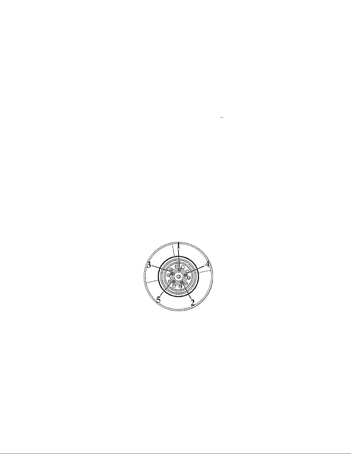
6.5,6 Remove the Lug Nuts and Wheel
6.5.7 Place Spare Tire on the axie and lighlen Lug Nuts between 95 - 120 ft /lb
Do not exceed 1.20 ft /lb
6.5.8 'Tighten Lug Nuts in the following sequence:
34
Page 35

633 L ower Tire Jack and remove from under Trailer
A
Never craw! under a trailer on jacks The trailer could slip off
the jack oi' the jack could fail resulting in serious injury' or death
A WARNING
Lug nuts are prone to loosen after initia! insiallalion, which can
ietHl to death or serious injury
Check lug nuts for lightness on a new trailer or when wheel(s)
have been remounted after the first 10. 25 and 50 miles oГdfi^■ing and after any impact.
Lug nuts for the tires must be tightened by the user befor e each
use, Sears cannot be held responsible for damages caused by
loosened lug nuts
6*6 Checking the Tire Piessure
Always check the lire pressure befbie each lotv Use a pressure gauge to ensure
proper tire pressure. The tires provided with your Trailer should be filled to 80 psi
Tire pressure must be checked when the tire is cold !f the ttailer has been towed
for at least one mile, allow at least three hours after a tow for the lire to cool before
checking the pressure
A
To help ensui'e long tread life and your safety. Always check
tire pressure to ensure optimum life and perfoiniance from your
tires The tires that came with your trailer should have a tire
pressure of 80 psi. Scars cannot be held responsible for dam
ages caused by uneven tread w'ear and blmv outs from an under
inflated or over-inflated tire ”
' ' .. . , .
................
WARNING
A
A
WARNING A
' “ "" “ *■* "
........................
—
35
Page 36

SECTION?: 30ADÎ\irrs3F.
TRAILER
LOADING THE CARGO
improper trailer loading causes many accidents and deaths To safely load a trailer,
you must consider:
■ Overall load weight;
• Load weight distr ibution;
• Proper tongue weight; and
• Securing the load properly
To determine that you have loaded the trailer within ils rating, you must consider
the distribution of weight, as well as the total weiglit of tiie trailer and its contents
The trailer axles carry most of the total weight of'tlie trailer' and its contents (Gross
Vehicle Weight, or “GVW”). The remainder oflhe total weight is carried by the tow
vehicle hitcii, For safe towing, it is essentia! that the trailer tongue and tow vehicle
hitch carry the propes amouiu of the loaded trailer weight, otheiwtse the trailer can
suddenly sway wildly at towing speed Read the ‘'Tongue Weight” section below
The load distribution must be such that no componetn pait of the trailer is loaded
beyond its rating. This means that you must consider the rating of the tires, wheels
and axles. For tandem and triple axle trailers, you must make sure that the front-torear load distribution does not result in overloading any axle
Towing stability also depends on keeping the center of gravity as low as possible.
Load heavy items on the floor and over the axles. When loading additional items, be
sure to maintain even side-to-side weight dish ibulion and proper tongue weight The
total weight of the trailer and its contents must never exceed the total weight rating of
the trailer (Gross Vehicle Weight Rating, or “GVWR,”) ”
A WARNING A
An Gverbaded trailer can result in loss of control of the Iraiter,
leading to death or serious injurj'
Do not load a trailer so that the weight on any tire exceeds its
rating
Do not exceed the trailer Gross Vehicle Weight Rating (GVWR)
or an axle Gross Axle Weight Rating (GAWR).
Tongue Weight
It is critical to have a portion of the trailer load carried by the tow vehicle. That is,
the trailer tongue must exert a downward force on the hitch. This is necessary for W'o
reasons First, the proper amount of tongue weight is necessary for the row vehicle
to be able to maintain control of the tow vehicle/trailer system If, for example, the
36
Page 37

tongue exerts an upward pull on the hitch, instead of pushing down on it (because
the trailer is overloaded behind its axle(s)), the rear wheel of the tow vehicle can
lose traction or grip and cause loss of control. Also, even if there is some weight on
the tongue, but not enough weight on the tongue, the trailer can suddenly become
unstable at high speeds.
If, on the other hand, there is too much tongue weight, the front tvheels of the tow
vehicle can be too lightly loaded and cause loss of steering control and ttactioti, as
well, if the front wdieels are driving
In addition to tow vehicle control, tongue weight is necessary to insure that the trailer
axle(s) do not exceed their Gross Axle Weight Rating (GAWR),
The table below has ‘huks of thumb” for proper tongue weight
Irr the table below, the second column notes the rule of Thumb percentage of total
weight of the trailer plus its cargo (Gross Vehicle Weight, or “GVW") that should
appear on the tongue of the trailer For example, a trailer with a bail hitch and a
loaded weight of 1.000 pounds, should have lO-l .5% of 1,000 pounds on tire tongue
That is, the example trailer would have no more than 100 to 150 pounds on its tongue.
37
Page 38

7J. CHECKING THE TONGUE WEIGHT
Fo check the longue weight, the tow vehicle and nailer must be on level ground, as
they will be when the trailer is being towed
If you know the weight on your tow vehicle axles when you are nor towing a tiailer,
trailer tongue weight can be determined with the use of a truck axle scale.
The recommended method of checking tongue weight is to use an accessory called a
“longue weight scale ” If a tongue weight scale is not available, you cart check the
tongue weight using a bathroom scale
Using a bathroom scale to check longue weight: The loaded trailer must be on a
smooth and level surface, and you must block the trailer wheels, front and rear
7.1.1 Checking Tongue Weight— Using a lever and bathroom scale
Cl O O C5
A WARNING
An unrestrained trailer can fall off its support, resulting in seri
ous injuiyf 01“death,
A
i
Before checking tongue rveight, block trailer wheels, front and rear
• Raise the tongue of the trailer with the tongue jack
■ Place a bathroom scale on the ground, directly below the couplet,
• Place a strong block support (such as a cement block) on the scale -- note the
scale reading for the weight of the block support,
• Lovvei the tongue until the coupler rests on the block support and the jack is ‘/2
inch above the ground
• The scale reading, minus the weight of the block support is the tongue weight
7,2 Securing the Cargo
Since the trailer ‘Tide” can be bumpy and rough, you must secure your cargo so that
it does not shift while the trailer is being towed.
A
Shitting cargo can result in loss of control of the trailer, and can
lead to death oj serious injury'
Tie down all loads with proper sized fasteners, ropes, straps, etc.
WARNING
A
Loading Cargo
7,2.1
Couple the trailer to the low vehicle before loading This is essentia! because the
longue can rise during loading, befóte the cargo is properly distributed To
measure the tongue weight, you will have to uncouple the trailer after it is loaded
Do not transport people in the trailer Do not transport comainers of hazardous
substances, cans or containers of flammable substances, such as gasoline.
38
Page 39

kerosene, paint, etc However, f^ud in the tank of an ofF-road vehicle, or a car or
motorcycle, etc, may be carried on your open trailer.
A
Do not transport t1a,mmab[e, explosive, poisonous or other
dangerous materials in your trailer Failure to heed this warning
could resuH in property damage, serious injury and death
Exceptions:
• Fuel in the tanks of Vehicles that are being towed
• Fuel stored in proper containers used in trailer living quar
ters for cooking
• Fuel stored in the lank ofan on-board generator
7.2.i.! Pi eparing the Trailer for Loading
Before loading cargo onto the trailer:
* inspect the deck of the trailer for corrosion or damage; and
* inspect the hold down openings and/or ‘'ff’-tings. Hold down openings must
be sturdy wdth no visible cracks or kinks D-rtngs must be light to the deck and
must not be bent
If the deck or any required hold-down is damaged, do not load the cargo Bring
the trailer to your dealer or a competent repair service before using it to cariy^
cargo
A
Damaged or loose "D’'-rings can break, allowing cargo to become
loose inside the trailer Loose cargo can shift the center of gravity,
and result in loss of control of the trailer
Inspect “D^’-rings, and lest them for looseness before loading
cargo
Do not use a damaged or loose ‘•D"-ring to secure cargo.
Failure to head this warning could result in }3roperty damage,
serious injury' and death.
WARNING
WARNING
_________________________________
A
A
7-2.1.2 Loading flic Trailer'
Before loading the trailer, couple the trailer to the low vehicle and ensure the
deck is level. Do not load or unload the traiiei' when the deck is not level or
when the Trailer is not coupled to the tow vehicle
1 Ensure the lop of the ramp (or ramps) is secure to tire trailer, and the bottom
is resting on firm ground Pockets may be provided to hold the ramp to the
frame of the trailer
2. Load the cargo onto the trailer,
3 Secure ihe Cargo to the trailer using approptiale straps, drains am! tensioning
devices
39
Page 40

Since the tiailer “ride’" can be bumpy and rough, you rausi secure your cargo so
that it does not sltifl while the trailer is being towed
A
Load can suddenly move or Urpple, which can result in death or
serious injury
Do not load or unload your open trailer unless it is prevented
from tipping and is on firm and level ground
4 Return the ramp(s) to tlteir stowed posiiion{s), and secure them so lliat they will
not move during transit
A
Shifting cargo can result in loss of control of the trailer, and can
¡lead to death ot serious injury
Fie down all loads with proper sized fasteners, ropes, straps, etc
A
Before loading Trailer. Trailer must be properly connecied to the
Tow Vehicle This stabilizes the Trailer Faihire to follow this
warning could result in property damage, personal injury and
death.
A
Do NOT use the Gates for tie-down locations All articles being
towed must be tied to the side walls of the frailer. Gates can
dislodge causing property damage and possible injury or death So
other' motorists and pedestrians
..
“Д'Ду-'ГяГТТ’гГ
WARNING
WARNING
.....
,■ -
WARNING A
WARNING A
-----------------------------------
A
A
-
Ж
Do not transport рео|з1е in the trailer Failure to heed t Its war
ing could
damage, p
40
result in serious injury such as broken bones,
analysis or death
WARNING
A.
brain i
1
Page 41

ECTION 8: CHECK TRAILER
BEFORE & DURING TOWING
PRE-TOW CHECKLIST
8-1 Before Towing, Double Ciieck Ali These Items:
■ Tires, wheels and lug nuts (see the section “Breaking in New Ttailer“ and the
section “Tire & Safety Information“
• Couples secured asid locked (see Ihc section “Coupling to the Tow Vehicle’")
• Safety chains properly rigged to tow vehicle, not to hitch or ball (see the section
“Coupling to the Tow Vehicle” of this manual)
• Test of lights: Tail, Stop, Turn and Backup
• Cargo properly loaded, balanced and tied down (see the section “Loading the
Trailer” of this manual)
• Tongue weight
• Doors and gates latched and secured
• Flares and reflectors
A WARNING A
Art improperly coupled trailer can result in death or serious
injuiy
Do not move the trailer until:
* The coupler is secured and locked to hitch;
* The safety drains are secured to the tow veliide; and
* Assist Wheel is fully retracted
* You secure Tongue to Bed using Locking Pin and Cotter Key.
Do not tow the trailer on the road until:
* Tires and wheels are cliecked;
* The load is secured to the trailer; and
* The trailer lights are connected and checked.
' ■ ........
MAKE REGULAR STOPS
8.2 Arter Each 5(! Miles, or One Hour of Towing, Stop and Clieck the Following
Items:
• Coupler secured
• Safety chains are fastened and not dragging
• Cargo secured
• Cargo door latched and secured
41
Page 42

A WARNING
Since roads can be bumpy and rough, lug nuts can loosen over
time and even separate from ihe wheel and possibly causing the
separation of the wheel from the trailer The lug nuts must be
tightened by the user before each use.
The tires must be maintained at the proper tire pressure before
each use Sears cannot be held responsible fot damages caused
by loosened iugnuts, or uneven tread wear and blow outs from
an under inflated orovci inflated tire
Fatlute to heed these warning.s could result in persona! injiny’,
property damage and death
A
A WARNING
Do NOT use the Gates for tie-down locations All artides being
towed must be tied to the side walls of the Trailer Gates can
dislodge causing property damage and possible injury or death to
other motoi ists and pedestr ians
Follow posted speed limits but do not exceed 65 mph
A
fiJo not transpoit people^^i Failure to heed this warn
ing could result ii? serious injury such as brokesr borres, brain
damage, paralysis or death
WARNING
......... .................
A
A
, “W:
42
Page 43

sKi-'nii":, •); liRi-: j'--.
NEW TRAILER
LUG MUTS & TIRE PRESSURE
9.1 Retigbtening Lug Nuts at First 10, 25 & 50 Miles
Wheel lugs can shift and settle quickly after being fiist assembled, and must be
checked after the first 10, 25 and 50 miles of driving and after any impact Failute
to perform this check may result in a wheel coming loose from the trailer, causing a
Clash leading to death oi serious injury.
A
Lug nuts are prone to loosen after initial installation, which can
lead to death or seriou.s injury,
Check lug nuts for tiglitncss on a new trailer or when wheel(s)
have been remounted after die first 10, 25 and 50 miles of driv
ing and after any impact.
A
The kig nuts for the tires must be lightened by the user before
each use The tires must be maintained at the proper tire pressure
before each use. Sears cannot be held tesponsible for damages
caused by loosened lugnuts, or uneven tread wear and blow outs
from an under-inflated or over-inflated tire
Failure to heed this warning could result in property damage,
serious injury and death.
WARNING
.
.............
WARNING
.
A
A
A WARNING A
If low vehicle brakes do not work properly, dcatli or serious
injury can occur.
Road test your tow vehicle’s brakes in a safe area at no more
than 30 mph before each tow.
9.2 Tire Pressure
Check the pressure in each tiie to ensure die is set to the tri e manufacture! s
recommended pressure The tires that came with your trailer should be filled to
SO psi. Use a tire gauge to get an accurate reading. You should clieck the pressure
before each tow
.
43
Page 44

SECTION 10: MAINTENANCE!
INSPECTION, SERVICE & MAINTENANCE
10,1 Inspection, Service & Maintenance Summary Charts
You must inspect, maintain and service youi trader regularly to insure safe and
reliable operation., If you cannot or are unsure how to perform the items listed here,
have your dealer perform them
Note: In addition to this manual, also check the relevant component
manufacturer’s manual.
inspection and Service before Each Use
Item Iiispcetiim/SeEvicc Manual Setlfort Reference
Coupler and Hitch Ball
Safety Ciumi(s) & Hooks
Tires
' Air Pressure
Wheels
* t. ugWuts fBolK) & tilth
Check for cracks, piis, anil
flttU Itcpiacc w/hal! & coupler
having rrailcf GVW Rating
Grease
Check locking device & replace
Check for wear and damage
Check lire pressure when cold
Inilnte lires ui 3(! [ssi
Check for riglitness
Tighten to 95 - 120 iVlh Do
not exceed 120 ft /!b For new
and fcrnountcd wheels, check
torque after firsl 10. 25 & 50
mites of driving and aflcr any
impact
Section 102 3 1
Sections 8.1 & 8.2 i
Sections 6 6, 92 & 102 6
SociiM6 5 7&9 1
Sections 10 2 8, 1028 1 & 10 29 1
Inspection and Service each 3 Months or 3,000 Miles .................................................
Ilc:m InspcciJOH/Scrvjcc |V‘]«iiiU!il Itcfcrcii-Cc
Stmeture
■ Hinges, Doors
Wheels
• Rims
Tires iMpeet for cuts wear ami
Inspect Repair or replace
damaged, worn or broken parts
inspect for dents. (lamagB or out
of round
bulging
Oasie lire maintcnaiicc
Section 102 2 !
10.2 7
Sections 6 4, 6 4 1,6.4 2,64 3,
6 4 4,64 5,6.4 6,64,7,64 8,
6.4,9, 5,4,10, 6.4.n, 6.5 & 10.2.6
Inspection and Service each 6 Months or 6,000 Miles /
lleti! Inspccifon/Scrvtce Manual Section Reference
Tires
Wheels
• UNSEALED Bcittings (Mute)
44
Rotate @ 5,000 mile,<i Section 10.2,6
Ciieek and etmiirm free running
Replace if not
Disassemble / inspect / as
semble and repack Replace
promptly ifirttmersed in xvater
Section 10 2 7 & 10 2 8
Section 10 2 8 1
Page 45

Inspection and Service each 6 Months or 6,000 Miles
Snspension
Inspection and Service Each Year or 12,000 Miles
Item
Slruciure
• Frame members
• Wdds
• Slit!c-t)in
Structure
• Axle Attaclimenl Bolls
10.2 Inspection and Service Instructions
H).2J Axle Bolls, Frame, Suspension, & Structure
Inspect for bending loose faS“
tetters, wear
InspcciiBti/Service Mtmua! Sttlion RcfercncE
htspeci all fratsm members, bolls
& rit'eis Repair or replace ditmaged, wum or broken pans
itispeei alt weWs Repair as
needed
Clean dirt build-tip I ubricaie
slides, shafts ami iiears
CliCflk WITH DEALER
Section 10 2 it!
Section 10 2 2
SettiDW 10 2 2 1
Section (0 2 22
Section 10 2 !
A
Worn or broken suspension pans can cause loss of comrol and
property damage, serious injuty and death may result. Have
trader professionally inspected annually and after any impact
iTo perform many of the inspection and maintenance activities, you must jack up the
I trailer.
When jacking and using jack stands, place them so as to clear wiring and suspension
parts (springs, torsion bars, etc.) Place jacks and Jack stands itisids of die perimeter
strip on the supporting structure to which the axles are attached.
WARNING
WARNING
Never crawl iinderyourtrailer unless it is on firm and level ground
and resting on properly placed and secured jack stands
Never attempt to change the tire while trailer is in folded
position Trailer can tip over
Failure to heed these warnings could result in property damage,
serious injury and death.
A
Do not use the Assist Wheel to support the Trailer while
changing your tires, Frailer could tip over causing serious injury
or death. .
■ . . _
........
■ ■ . ' '
WARNING
A
A
45
Page 46

lft,.2,2 Trailer Structure
Because the tmiler lloor receives the most abuse, it wH! most likely corrode before
any otlter part of the strucwre Using a power washer, wash the floor and tvalls of
the trailer after each use
10,2.2.1 Fasteners and Frame Members
Inspect a!! of the fasteners and stmctural frame members for bending and other
damage, cracks, or failure Repair or replace any damaged fastener and repair the
frame inember Ifyou have atiy questions about the condition or method of repair
of fasteners or frame members, get the recommendation of, or have the repair done
by your dealer
The various fastener types used on your trailer are:
• Bolts, which are used mainly for attaching door and gate hinges to the trailer'
body;
• Buck Rivets, which are used to attach the sides and roof panels of the body to
each other, and to the frame of the trailer; and
• Huck Bolls may be at various locations on the sub-frame Huck bolts are not
user serviceable. Ifyou detect a loose huck bolt fastener, do not tow the trailer.
Call your dealer for insttnetions
A WARNING
Broken or damaged fasteners or welds cats cause serious injury,
damage to trailer and contents and death Inspect for, and repair
all damaged parts at least once a year-
A
10.2.2.2 Welds
All welds can crack or fail when subjected to heavy loads or movement of cargo
that w'as not properly tied to prevent movement Any time you know' or suspect
the trailer has been subjected to heavy loads or movement of cargo, immediately
inspect tite welds and fasteners for damage To prevent severe damage to your
46
Page 47

trailer, inspect all of the welds for cracks or failure at least once a year
A WARNING
Improper weld repair will lead to early failure of the trailer struc
ture and can cause serious injury' or death. Do not repair cracked
or broken welds unless you Iiave the skills and equipment to
make a proper repair If not, have the welds repaired by a certi
fied welder
10.2.3 Trailer CoiiHcction to Tow Vehicle
I0-2.3J Coupler and Ball
The coupler on the trailer connects to the ball attached to the hitch on the tow
vehicle, The coupler, ball and hitch transfer the lowing forces betrveen the
totv vehicle and the trailer Before each lowy coat the ball with a thin layer of
automotive bearing grease to reduce wear and ensure proper operation; and check
the locking device that secures the coupler to the ball for proper operation
ff you see or feel evidence of wear, such as flat spots, deformations, pitting Oi
corrosion, on the ball or coupler, immediately have y'our dealer inspect them to
determine the proper action to prevent possible failure of the ball and coupler
sysiera All bent or broken coupler parts must be replaced before towing tlie trailer'
The coupler handle lever must be able to rotate freely and automatically snap into
the latched position. Oil the pivot points, sliding surfaces, and spring eirds with
SAE 30W motor oil. Keep the ball pocket and latch mechanism clean Dirt or
contamination can prevent proper operation of the latching mechanism
A
I
When replacing a ball, the load rating must match or exceed the GVWR of the
trailer
10.2.4 dack
If a grease fitting is present, you must use a gi ease gun to lubricate the jack
cneci'sanism Grease the gears in the top of hand-cranked jacks once a year; by
removing the top of the jack and pumping or hand packing grease iruo Ute gears
10.2.5 Lights and Signals
Before each tow, check the trailer taiilights, stoplights, turn signals and any
clearance lights for proper operation
A WARNING
Imjtroper o|jeraling taiilights, stoplights and turn signals can
cause collisions Check all lights before each toW' Failure to
heed this warning could result in property damage, serious injury
and death._______________________________________________
''i
---------
;—■;—; —^ ^ ^ ^ ;
47
Page 48

ЮЛ.б Tires
Before each tow, be sure the tire pressure is at the \faJue indicated on the sidewall
Tire pressure must be checked while the tire is cold Do not check the lire pressure
immediately after towing the trader Allow at least three hours For a lire to cool, if
the trailer has been towed for as much as one mile Replace the tire before lowing
the trailer if the tire treads have less than 1/16 inch depth or the telltale bands are
visible
A bubble, cm os bulge in a side wall can result in a tire blowout Inspect both side
walls of each tire for any bubble, cut or bulge; and rejrlace a damaged lire befóte
towing the trailer
Tires do not wear evenl^f Depending on the toad balance, some will wear faster
than others. To help increase the life of your tires, rotate tires every 5000 miles
A WARNING
Worn, damaged or under'inflated tires can cause loss of coiuroi,
resulting in damage, serious injury and possibly death Inspect
tires before each low
A
10.2.7 Wheel Rims
If the trailer has been struck, or impacted, on oi' near the wheels, or if the trailer ha.s
struck a curb, inspect the rims for damage (e g , being out of round); and replace
any damaged wheel Inspect the wheels for damage every year, even If no obvious
impact has occurred Also check the tires to ensure they’re at the recommended
pressure
H).2.8 Wheels, Bearings and Lug Nuts
To check your bearings, jack trailer and check wheels for side-lo-side looseness
If the wheels are loose, or spin with a wobble, the bearings must be serviced or
replaced
Most trailer axles are built with sealed bearings that are not serviceable Sealed
bearings nriist be replaced as complete units
10,2.8.1 Unsealed Bearings (Hubs)
You must inspect and lubricate the bearings once a year or evesy 12,000 miles to
insure safe operation of your trailer
Tf a trailer wheel bearing is immersed in Water, it must be replaced
It your trailer has not been u.sed for an extended amount of time, have the bearings
inspected and packed more frequently, at least every' six months and prior to use
Follow the steps below to disassemble and service the UNSEALED wheel
bear! n as
48
Page 49

• A Tier removing the grease cap, colter pin, spindle nut and spindle washer,
iemo\ie the hub and drum to inspect the bearings for wear and damage
• Replace bearings that have flat spots on rolieiS, bioken roller cages, rust or
pitting. Always leplace bearings and cups in sets The inner and outer bearings
are to be rejiiaced at the same time
• Replace seals that have nicks, tears or wear
• lubricate the bearings with a high quality l:.P-2 automotive wheel bearing
grease
Evety time the wheel hub is lemoved and the bearings arc reassembled, follow the
steps below to check the wheel bearings for free runrsing and adjust
• Turn the hub slowly, by hand, while, tightening the spindle nut, until you can no
longer nnn tlie hub by hand,
• Loosen the spindle not just until you are able to tuin it (the spindle mit) by
hand Do not tain the hub while the spindle nut is loose
■ Put a new cotter pin through the spindle mil and axle
• Check the adjusttnents Botli the hub and the spindle nut should be able to
move fi’eely (the spindle nut motion will be limited by the cotter pin)
10.2,9 Lug Nuts (Bolls)
Lug nute ate prone to loosen right after a wheel is mounted to a hub When driving
on a remounted wheel, check to see if the lug nuts are tight after the first 10, 25 and
50 mites of driving and before each tow thereafter
A
lug nuts ate prone to loosen after initial installation, which can
lead to death or serious injury
Check, Iitg nuts for tiglitness on a new trailer or when wheel(s)
have been remounted after the first 10, 25 and 50 miles of
driving
A
Metal creep between the wheel rim and fug nuts will cause rim to
loosen and could result in a wheel coming off, leading to death or
setiotis injury. Tighten lug nuts before each tow
A
Do not use the Assist Wheel to support the Trailer while
changing your tires frailer could tip over causing serious injury'
or death.
________________________________
j— ^
WARNING
WARNING
WARNING
________
A
A
A
__
49
Page 50

Figure 10-2: Lug nut sequence of tightening
Tighten the lug nuts to the proper torque for tiie axle size on your iraiier, to prevent
wheels from coming loose. Use a torque wrench to tighten the fasteners If you do
not have a torque wrench, tighten the fasteners with a iug wrench as much as you
can^ then have a service garage or dealer tighten the lug nuts to the proper torque,
Over-tightenirig will result in breaking the studs or permanently defomiing the
mounting stud holes in the wheels. Do not exceed 120 ft,/lb
10.2.10 Suspension
All suspension components should be visually inspected at least every 6000
miles or 6 months, Check for loose fasteners and tighten to proper torque values.
Excesively worn or damaged parts should be replaced with original parts,
SO
Page 51

Bed Frame Assembly and Parts
ro Part Nb.
EK 1024863 Diitmond Plate Side Pane!
BC 1010043
BD 1024948 Gals Pusher
BE 1023985 Gate Pusher Snnng
BF
BQ
BH
BÍ 1025184
BJ 300013 3/r-i6NyiockNut
BK 1025177 3/r-16x3” Hex Boil
BM
BN 1025799 Bed Locating Tab
BO 1024906
BP 1025800 Pin Relamer Bracket
BQ 1024905
BR 1028124 Right Fíame Weidmem
BU
BV
DT 1019803
102322S
1023984 Gale Pusher Pin
1ОШ03О Tail Lsgist (Right)
1024946 Bed Lift Guide
1024904 Bed Tube Weidraent
1024903 Rear Tube Weldment
Description
Amber Marker Light
3/4" Roll Pin
3/r-l6x2 Ш” Hex Bolt
Short J-Cbannd
Front Bed Tube Weldment
1/4’'-20 Kens Nut
To order parts, call our customer service department at 1-800-422-3865.
Page 52

Bed Frame Assembly and Parts
m
8A 1026464 Diamond Plate Side Pone!
BB 1D1647É Tail LighI (Left)
SC 1010045 Reflector Ligin
Bl 1025184 3/8”46 X 2 1/2” Hex Bolt
BJ
BL 102SI23 Left Side Weldment
BS 1024902 Long J-Chmmel
ВТ 1024900 Hal Cliannel WeWmenl
flW 1024899 Rear Hal Channei Weldmem
BX 1012733 Assisi Wiieel
BY
BZ 1024941 Assist Wheei Spring
DF 1025187 l/2”-13 X 3” Hex Bolt
DT 1019803
FA Ш24865
Pars Nú.
300013
1025180
Dcscripiioi)
3/S”.i6NylockNtit
l/2”-13NyloekNiit
l/4”-20 ICeps Nut
Caster Weldmem
To order parts, calí our customer service depanraem at l-SOO-422-3865.
Page 53

Tongue Assembly and Parts
DB
^7 DA
/
if
n /
V
i
Q
h
é
■A?
To order parts, call our customer service department at l-S0t)-422-3S63.
oi
k
Ci
n
(y
cj
§
\\, DO
't
DP'-IP»«
DM •
/
.
voiding Jack
D DD
DM
ID
BJ
BY
DA
DB
DC
DD
DE
DF
DG
DH
Df
DL
DM
DN
DO
DP
DQ
DR
DS
DU
DV
DH (4)
Part No.
300013
1025180
1012278
1011472
1025941
1025862
I024S58
1025187
1014296
300137
1025227
1027957
1027959
1026!IS
102565!
1024329
1027958
1025798
300031
1025751
1019384
■:í-DS
DS
BJ
Description
3/8"-16Ny!ockNut
l/2"-]3 NyiockNut
Safaty Cham
Coupler
Toiigtw Weldment
.Alignment Guide Tube
Axle AcEUfltor Tube
l/2”'I3 X 3” Hex Boil
410 X 3/4" Self-Tapping Screw
3/8”-16 X 1” Hex Boil
!/r-I3x2”Hex Bolt
l/4”-2Sx I 1/4" Hex Bolt
!/4"-2S Ccmcriock Nut
Folding Jack
Jnck-to-Asle Bracket
Jack Spacer
l/4”-28 X 2 1/4" Hex Balt
Crank Plate
3/8” Standard Washer
3/S”-I6 X I 3/4" Hex Bolt
3/S”-16x I 1/4" Tap Bolt
Page 54

Axle Assembly and Parts
ID Pnrt No.
BY 1025 ISO
ICA ¡025181
jcc
|CD 1027274
iCE i026130
ICF
jCG
jCH 1C27352
ICi ¡021745
ICJ 1009585
CK
CL 1016243
CM
CO 1024795
CP
CQ
CR
J022781
1009889
1025192
1010432
1D251S6
1025179
1012279
1024860
cs 1025435
Dcscriptian
l/2”-13Nylock Nut
l/rC3x*6” Hex Boll
3/S” U-Bols
LeafSpnna
LeafSpring Brackei
9/16” X 2.925” Standard He.x Boit
3/8"-24NylockNiH
Leaf Spring Spindle Weldment
Hub
Tire
Rim
Lug Nut
1/2” Standard USS Wasrtar
Center Axle Assembly
J/2”-l3 X 4 i/2” Hex Bolt
Chrome Hub Cap
U-Brackel
1 i 4 S lotted Axie N lit
CA
cm!/,.*
CC
,cz
ID
CT
cu
cv
cw
cx
CY
cz
Part No.
!025431
1025433
1025434
1025436
1025437
1015762
1016915
Description
3 l/!6" Bearing
Dust Cap
Seal
1 ” SpmdJc Washer
1/8” X 2’’ Cotter Pin
Pivot Piate
9/16” Standard HexNul
f'O’W
To order parts, call our customer service department at I-8Q0"422"3865.
TJ-
lO
Page 55

Miscellaneous Parts
\mr '■w'” \«-r
EC
^
"AE
f
_
j ■
1
nl^ 'fiMr
ED
10 Part No.
AB (022895
AC t025072
AD i02505i Locking Pin w/ Lanyard
AE 1016242
\
\
DG 1014296
EA 1026123
ES 1024910 Diiirtsond Plate
EC 102344S
ED ¡023444
EE
EF 1025216
EG ¡023050
EH 1016473
Ef
EJ 1015282 Wiring Conduit (Not showni
EK
EL ¡028013
1026660
1016474 Wiring Harness {Nat shown 1
¡025052
Description
Hand Crank
2” X 4" X 63" Distance indicator
3" Cotter Key
#10 X 3/4” Seif-Tappmg Screrv
Gate VVeidment
Left Decking (Wide!
Right Decking (Narrowl
Hand Crank Holder
Rubber Wiring Qrommcl
3/4" Rubber Wiring Oroinmet
License Plate Holder
Assist Wheel Rubber Bumper
Jack Retainer Clip
cn
OIL
AO
i..
To order parts, cal! our customer service department at i -800-422-3865.
Page 56

....
SECTION 12:‘WARRANTY
.........
INFORMATION
Limited Warranty on Craftsman Fold»Up Trailer
When operated and raaintained according to all supplied product inslnictions, if
the following components of this Craftsman Fold-Up Trailer fail due to defects in
material or workmanship within the time periods listed below, call 1 -800-422-3865 to
anruige for ft-ee repair
• Two Years: All components except tires, wheels, hubs, springs and axle
• One Year; Tires, wheels, hubs, springs and axle
This warranty does not cover:
• Scratching or scuffTng of the product that may result from normal use
• Defects resulting ffoni intentional damage, negligence, unreasonable use, improper
loading, overloading, installation of improper equipment, improper towing, and
failure to ensure lug nuts are tight.
• Liability for incidental or consequential damages to the extent permitted by law.
While every attempt is made to embody the highest degree of safety in this trailer,
freedom from injury cannot be guaranteed The uses assutnes all risk of injury
resulting from use of this product.
This wwranty gives you specific legal rights, and you may also have other rights
which vary from state to state.
56
Seats, Roebuck and Co ., Hoffman Estates, IL 60179
 Loading...