

Page 1
Owner’s Manual
CRRFTSMRN
10-in. BANDSAW
1/3 HP MOTOR
Model 119.214000
CAUTION: Before using this
product, read this manual and
follow all its Safety Rules
and Operating Instructions.
Sears, Roebuck and Co., Hoffman Estates, IL 60179, U.S.A.
www.craftsman.com
• Table of Contents
• Full One Year Warranty
• Safety Instructions
• Assembly
• Getting to Know Your Bandsaw
• Adjustment
• Operation
• Maintenance
• Troubleshooting
• Electrical Schematic
• Parts List
• Espanol, p. 12
Page 2

TABLE OF CONTENTS
Table of contents................................................................................................................................................................................... 2
Full one year warranty............................................................................................................................................................................2
Safety instructions..................................................................................................................................................................................2
Assembly..................................................................................................................................................................................................4
Getting to know your bandsaw
Adjustment...............................................................................................................................................................................................6
Operation..................................................................................................................................................................................................8
Maintenance
T roubleshooting..................................................................................................................................................................................... 9
Electrical schematic................................................................................................................................................................................9
Parts list............................................................................................................................................................................................... 10
Español................................................................................................................................................................................................... 12
........................................................................................................................................................................................... 8
........................................................................................
«.r..................................................................5
FULL ONE YEAR WARRANTY
If this Craftsman tool fails due to a defect in material or workmanship within one year from the date of
■purchase, CALL 1-800-4-MY-HOME® TO ARRANGE FOR FREE REPAIR. ^
If this tool is used for commercial or rental purposes, this warranty will apply for only ninety days from the
date of purchase.
This warranty applies only while this tool is in the United States.
This warranty gives you specific legal rights, and you may also have other rights, which vary, from state to
state.
Sears, Roebuck and Co., Dept. 817WA, Hoffman Estates, IL 60179
SAFETY INSTRUCTIONS
GENERAL SAFETY WARNINGS
KNOW YOUR POWER TOOL. Read the owner’s manual carefully. Learn the tool’s applications, work capabilities, and its specific
potential hazards.' .
ADANGER
ADANGER
m
ADANGER
Always Ground Ail Tools.
If your tool is equipped with a three-pronged plug, you must plug it into a three-hole electric receptacle. If you use
an adapter to accommodate a two-pronged receptacle, you must attach the adapter plug to a known ground. Never
remove the third prong of the plug.
Always Avoid Dangerous Environments.
Never use power tools in damp or wet locations. Keep your work area well lighted and clear of clutter.
Always Remove the Adjusting Keys and Wrenches from Tools after Use.
Form the habit of checking to see that keys and adjusting wrenches are removed from the tool before turning it on.
Always Keep Your Work Area Clean. Cluttered areas and benches invite accidents.
Always Keep Visitors Away from Running Machines.
All visitors should be kept a safe distance from the work area.
Always make the Workshop Childproof.
Childproof with padlocks, master switches, or by removing starter keys.
ADANGER
Never operate a tool while under the influence of drugs, medication, or alcohol.
Page 3

шашая
ADANGER
ADANGER
ADANGER
Always Wear Proper Apparel.
Never \wear loose clothing or je\welry that might get caught in moving parts. Rubber-soled footwear is
recommended for the best footing.
Always Use Safety Glasses and Wear Hearing Protection.
Aiso use a-face or dust mask if the cutting operation is dusty.
Never Overreach.
Keep your proper footing and balance at all times.
Never Stand on Tools.
Serious injury couid occur if the tooi is tipped or if the cutting tool is accidentally contacted.
ADANGER
Always Disconnect Tools.
Disconnect tools before servicing and when changing accessories such as blades, bits, and cutters.
*w Always Avoid Accidental Staring.
Make sure switch is in “OFP position before plugging in cord.
Never Leave Tools Running Unattended.
ADANGER
Always Check for Damaged Parts.
Before initial or continual use of the tool, a guard or other part that is damaged should be checked to assure that it
will operate properly and perform its intended function. Check for alignment of moving parts, binding of moving
parts, breakage of parts, mounting, and any other conditions that may affect its operation. A guard or other
>5
damaged parts should immediately be properly repaired or replaced.
SPECIAL SAFETY RULES FOR BANDSAWS
1. Always stop the Bandsaw before removing scrap pieces from table.
2. Always keep hands and fingers away from the blade. .
3. Never attempt to saw stock that does not have a flat surface, unless a suitable support is used.
4. Always hold material firmly and feed it into the blade at a moderate speed.
5. Always turn off the machine if the material is to be backed out of an uncompleted cut.
6. Check for proper blade size and type for thickness and type of material being cut.
7. Make sure that the blade tension and blade tracking are properly adjusted.
8. Make “relief’ cuts before cutting long curves.
9. 'Release blade tension when the saw will not be used for a long period of time.
10. Note and follow the safety warnings and instructions that appear on the lower door.
FOR YOUR OWN SAFfTY
1 READ AND UNDF RSlAND INSTRUCTION MAN JAl
BEFORE OPERATING DANHSAW
Z Always WC .T' cyr-
3 Do r'ot wt :i- ;rt
iJolNing
4 Ctiur k LI.iOp 'TiT.'iII:>0 onci makp c:cr1din thri! bCi'l:'
lE?i'‘tft f.Oirit ,in A-t;w.itU tGV,Trrf
5 Maintrl I o p’r.ipr'r ,irf j Lislmi'nt ot h Irici t- f ■■ k □ ;in ri
tension, Jjiado nt'C Ljt'nnnrjs
6 Keep hнпa^ out o1 pido rjf hi.irio
‘ii=r >■ J f'Wi*l ry G! iorl^.
’ Si'L i;-vhi'-• y u ,1 г о c V г г bi'forf 'opérai if!t|
Ô Adjust bKidu Çjurird giudr to jubi cJCiir лпгк piece.
9 ЛГГВ fji.-'Li- f'! (Til V .■ig.i!r>s| table and ui'H miter gage
ЛГЧ1 trr’:‘..r I.vhl'f: p C3i О i < ■
'0 Qo riru г..гт’г-vr vi'’'iTidd or cut-otf л'^соа untji hl?clt'
■ 1 Di'-cornei.’ rr’iacTir.i' ft r>m DO■^^Gr source t.fefore making
T.'ii.ti's cif ■id|o'i\rrM:r;ib
^2 0 о *ii-t г» pnSo t о n or l;sc :M damp lnc4t I oris
Page 4
ASSEMBLY
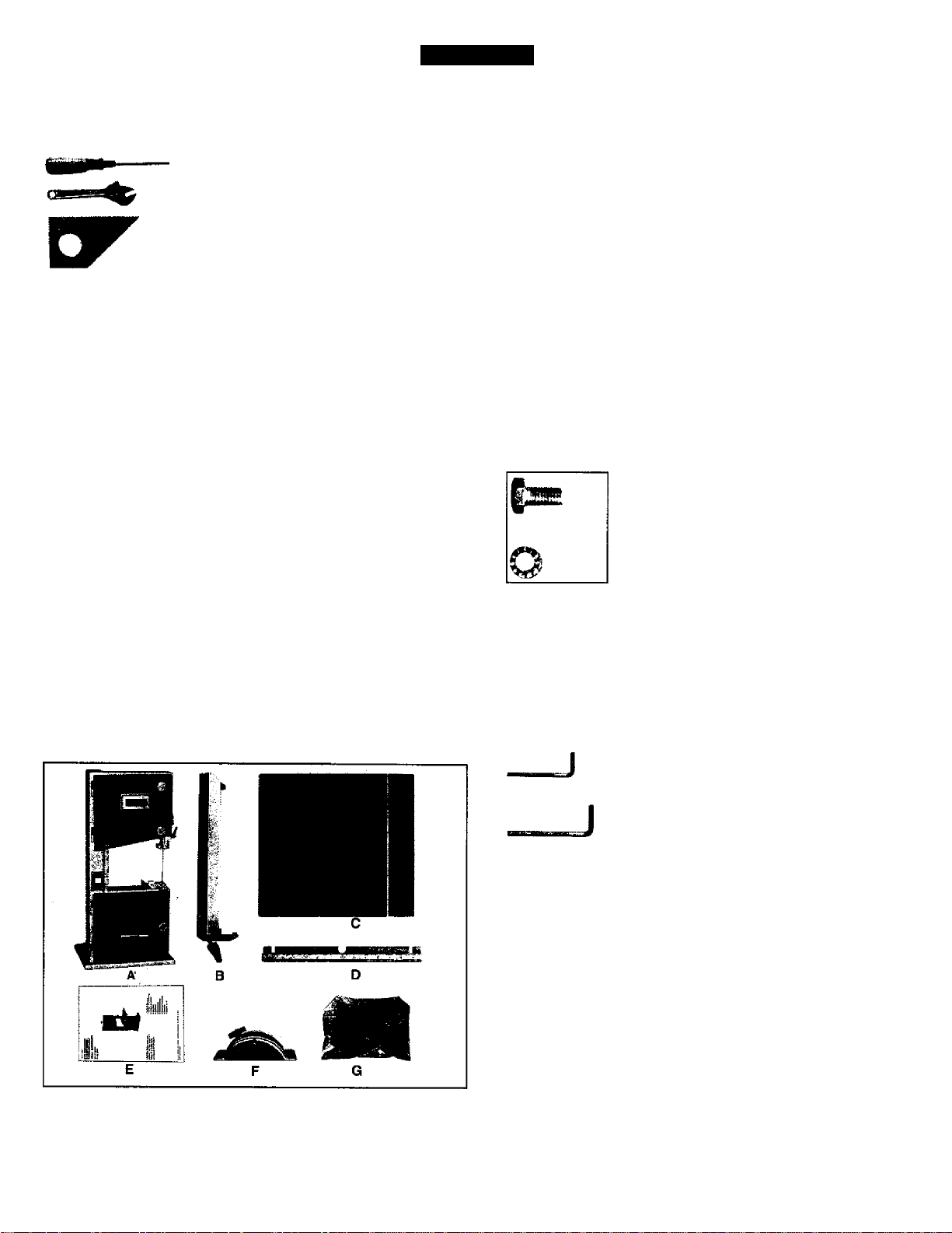
1. TOOLS REQUIRED FOR ASSEMBLY
Item
2. UNPACKING AND CHECKING CONTENTS
Model 119.214000 10” Bandsaw is shipped complete in
one box.
a. Separate all parts from carton and check each item with “Table
of Carton Contents” to make sure all items are accounted for,
before discarding any packing material.
b. Remove the protective oil that is applied to the table. Use any
ordinary house hold type grease and spot remover.
c. Apply a coat of paste wax to the table to prevent rust. Wipe all
parts thoroughly with a clean dry cloth.
Description Q’ty.
’ Medium Screwdriver
Adjustable Wrench..........................1
Square
.............................................
.....................
1
1
LIST OF LOOSE PARTS IN BAG
Item Description
Blade Tension Knob.,
•*
Miter Gauge..
Hex. Socket Head Cap Screw M6x30.......1
O
Washer 6..
Wing Nut M6..
Hex. BoltM6x12..........................................4
Lock Washer 6...........................................4
Q’ty.
CARTON CONTENTS
Item Description Q’ty.
A Main Machine..........................................................1
B Fence Assembly.................................................... 1
C Table........................................................................1
D Guide Rail
E Owner’s Manual.....................................................1
F Upper Table Trunnion Assembly.
G Bag of Loose Parts
...............................................................
........................
...............................................
1
1
1
star Knob Screw..
w-
Washer 6.
o
M3 Hex “L” Wrench..
M5 Hex “L” Wrench..
2. INITIAL ASSEMBLY
The machine is supplied partly assembled. Prior to use, the
following items have to be installed: Table, Blade Tension Knob
and Rip Fence.
WARNING: To Avoid injury, do not attempt to run or use this
machine until all parts are assembled and working properly.
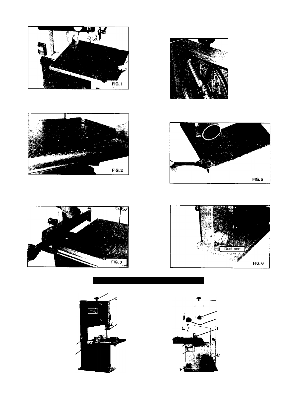
a. Assemble the upper table trunnion to the lower table trunion with
Carriage Bolt, Glide Piece, Washer and Wing Nut. Place the table
on to the upper table trunnion, taking care when passing the saw
blade through the slot of the table (See Fig. 1).
Locate four hex bolts and four lock washers from the bag of loose
parts. Mount the table to the upper table trunnion and install a bolt
with washer in each hole, then tighten with adjustable wrench.
Page 5
d. Place the blade tension knob on to the blade tensioner {See
Fig. 4).
b. Fasten the guide rail with two each star knob screw and washer
to the table. Use the hex socket head cap screw, washer and wing
nut for correcting the working table flatness. (See Fig. 2)
c, Lay the rip fence onto the guide rail. Adjust the rip fence parallel
to the saw blade. Tighten rip fence handle by pressing downward.
(See Fig. 3)
FIG. 4
e. To ensure sufficient upright stability of the machine it should be
bolted to floor, bench or worktable. For this purpose 6mm holes
are provided in the machine’s base. (See Fig. 5)
f. The bandsaw has a 2-1/2" dust port included. (See Fig. 5)
It is recommended that when in use, the bandsaw is connected to
a suitable dust collector.
Lock switch
Guide rail
GETTING TO KNOW YOUR BANDSAW
Blade tension knob
oor iocking knob
Blade guide
/Miter gauge
Upper table turnnion-'
Lower table turnnion"
Dust poi
Blade tracking knob
■Guide post adjusting knob
-enee
otor
Page 6
ADJUSTMENT
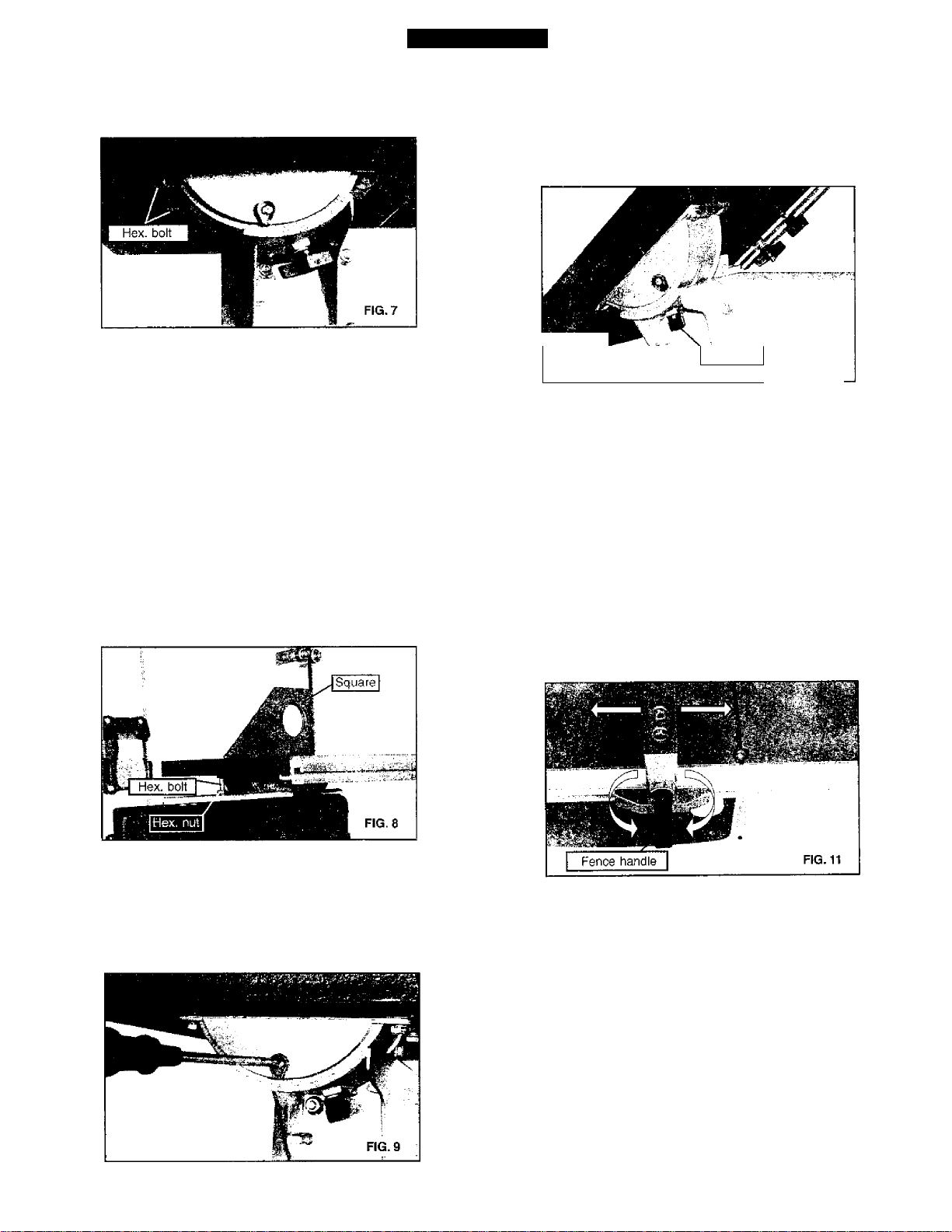
1. CENTERING THE TABLE
a. Loosen the four hex. bolts mounting the table to the upper table
trunnion. (See Fig. 7)
b. Move the table sideways as required, until the saw blade runs
through the center of the table insert.
c. if the adjustment of “b” is not enough to center the table, loosen
the four flange nuts holding the lower table trunnion and move the
table sideways to place the table in the center.
d. Re-tighten hex. bolts for trunnion, recheck the saw blade
position.
2. SETTING TABLE SQUARE TO SAW BLADE
Loosen the wing nut on the lower table trunnion and place a
suitably sized square against the saw blade. If the table requires
adjustment, proceed as follows:
a. Using a wrench, release the hex. nut on the frame. {See Fig.8)
b. Place the wrench on the hex. bolt and adjust until the table
square to the saw blade.(See Fig.8)
3. TILTING THE TABLE
For bevel cuts, the table tilts 0 through 45 degrees.
a. To tilt the table, loosen the wing nut on the table trunnion, set the
table to the required angle and tighten the wing nut again (See Fig.
10).
Wing nut
b. It is recommended to verify the correct angle setting using an
angle guide, or by making trial cuts in scrap wood. Adjust the
indicator accordingly by using a phillips head screwdriver.
FIG. 10
4. ADJUSTING THE RIP FENCE
The locking pressure of the rip fence has been factory-set, if
adjustment is required proceed as follows:
a. Raise the fence handle to horizontal position.
b. Turn the fence handle clockwise to increase clamping pressure,
counterclockvjise to decrease clamping pressure.(See Fig. 11)
c. After counterclockwise truning the fence handie, sliding the rip
fence to the desired position on the guide rai(.(See Fig. 11)
d. The fence handle has a cam action, press down the handle to
clamp tightly to the table after setting rip fence to desired position.
c. Tighten the hex. nut and recheck the saw blade and the table for
squareness.
d. Lock the table into position and check that the indicator reads
zero degree on the side of lower table trunnion. Loosen the screw
securing the indicator and reset if necessary to give zero degree
reading. (See Fig. 9)
NOTE: Do not adjust the fence handle such that excessive
pressure is exerted during operation - this may lead to deformation
of the end clamp at the rear of the rip fence. Set the fence handle to
apply just enough pressure to enable safe operation during
cutting.
5. CHANGING AND ADJUSTING THE SAW BLADE
This bandsaw is factory-equipped with a general-purpose wood
cutting blade, the saw blade is set prior to delivery.
To change the saw blade, the following procedure must be
followed:
WARNING: To avoid injury from unexpected starting, whenever
changing the saw blade or carrying out adjustments, switch the
bandsaw off and remove the power cord from the main outlet. To
avoid injury to hands when handling the saw blade, wear gloves
whenever necessary. .
Page 7

a. Remove the rip fence, the guide rail, the wing nut and screw
from the table.
b. Open the upper and lower doors by turning the door locking
knobs.
c. Loosen the blade tension by turning the blade tension knob on
the top of the upper wheel housing counterclockwise until the saw
blade has slackened (viewed from above) (See Fig. 12).
c. Set the blade guide to the required height by turning the guide
post adjusting knob.
d. Tighten the wing nut after setting.
8. ADJUSTING THE BLADE GUIDES
d. Remove the saw blade from the upper and lower wheels.
e. When fitting the new saw blade ensure the blade teeth are
pointing downwards and towards you at the position where the
saw blade passes through the table.
f. Re-tension the new saw blade and check the saw blade tracking
by turning the upper wheel by hand. The saw blade should run in
the center of the bandsaw wheels.
g. If need adjust the tracking of the saw blade, proceed as men
tioned below “ TRACKING THE SAW BLADE”
h. Replace the rip fence, the guide rail, the wing nut and screw to
the table.
i. Close the upper and lower doors by turning the door locking
knobs before reconnecting the power supply.
6. TRACKING THE BANDSAW BLADE
Set the tracking of the saw blade before setting the blade guides.
Once the saw blade is installed and tensioned, track the saw
blade by adjusting the tracking knob by hand (See Fig. 13). The
saw blade should run in the center of the bandsaw wheels. When
the correct adjustment is achieved lock the tracking knob with the
wing nut.
The Upper Blade Guide
a. To adjust the upper blade guides, first position the right and left
roller guides relative to the blade by slackening the ratcher handle
Fig. 15 and moving the guide carrier until both roller guides are
approximately 1/16” behind the gullets of the saw blade.
b. Set both roller guides to within 1/32” of the saw blade by
releasing the guide adjusting screw (A) Fig. 15 on each side of the
saw blade. Do not set the roller guides too close as this will
adversely affect the life of the saw blade.
c. Adjust the rear roller guide to be just dear of the back of the saw
blade by unlocking the guide adjusting screw (B) Fig. 15
d. When the correct adjustment is reached, lock the rear roller
guide in position with the guide adjusting screw (B) Fig.15
7. SETTING THE CUTTING HEIGHT
a. The upper blade guide should be set as close as practical
against the workpiece.
b. To adjust this height, loosen the wing nut at the side of the upper
wheel housing. (See Fig. 14)
The Lower Blade Guide
a. To adjust the lower blade guides, first position the right and left
roller guides relative to the blade by slackening the lock nut Fig.16
and moving the guide carrier until both roller guides are approxi
mately 1/16” behind the gullets of the saw blade
b. Set both roller guides to within 1/32" of the saw blade by
releasing the guide adjusting screw (C) Fig. 16 on each side of the
saw blade. Do not set the roller guides too close as this will
adversely affect the life of the saw blade.
c. Adjust the rear roller guide to be just clear of the back of the saw
blade by unlocking the guide adjusting screw (D) Fig, 16
Page 8

d. When the correct adjustment is reached, lock the rear roller
guide in position with the guide adjusting screw (D) Fig.16
9. CHANGING THE DRIVE BELT
a. Release the saw blade tension by turning the blade tension
knob on the top of bandsaw counterclockwise.
b. Using a M6 hex. “L” wrench (not provided) to release the hex.
socket head cap screw on motor mounting flange. (See Fig. 17)
OPERATION
c. Using a clip pliers (not provided) remove the retaining ring from
the center of the iower wheel.
d. Carefully slide the lower wheel forward and at the same time
release the saw blade from this wheel,
e. Remove the old drive belt and fit the new belt, (ensure ribs in
drive belt are seated correctly before reassembling and tensioning
the drive belt)
f. Follow procedures for CHANGING AND ADJUSTING THE SAW
BLADE & TRACKING THE BANDSAW BLADE, before restoring
power to the bandsaw and setting up for use.
WARNING: Before starting check if any part of your bandsaw is
missing, malfuctioning, has been damaged or broken... such as
the motor switch, or other operation control, a safety device or the
power cord, turn the bandsaw off and unplug it until the particular
For best results the saw blade must be sharp. Select the right saw
blade for the job, depending on|the thickness of the wood the cut to
be made. The thinner and harder the wood, the finer the teeth of
the saw blade. Use a fine tooth blade for cutting sharp curves.
part is properly repaired or replaced.
The machine is especially suited for cutting curves, but will also
The saw blade cuts on a continuous downstroke. To avoid injury
when hands are unavoidably near to the saw blade, they should
be placed on either side of the blade, not in line with it. Use a
push stick whenever possible when working in close proximity to
the saw blade.
Start the bandsaw by turning the lock switch on and wait for the
bandsaw to come to full speed before starting to cut. Never start
make straight cuts. Do not attempt to turn the workpiece without
pushing it, as this may cause the workpiece to get stuck, or the
saw blade to bend.
The rip fence is to enable safe and accurate straight cuts of the
workpiece, usually in the same direction as the grain of the timber.
The miter gauge is to enable safe and accurate crosscut of the
workpiece.
the bandsaw with the workpiece in contact with the saw blade.
The tiltable table is used for bevel cuts.
Slowly feed the workpiece towards the saw blade, putting only light
pressure on it. With both hands, firmly hold the workpiece down on
the table, and feed it towards the saw blade slowly.
WARNING: When sawing with the rip fence and a tilted table, the rip
fence must be installed on that side of the table which is tilted
downward.
MAINTENANCE
WARNING: To avoid injury due to unexpected starting, before
cleaning or carrying out maintenance work, switch off and discon
nect the bandsaw from the power source.
Never use water or other liquids to clean the bandsaw. Use a dry
brush.
Regular maintenance of the bandsaw will prevent unnecessary
problems.
a. Keep the table clean to ensure accurate cutting.
b. Keep the outside of the machine clean to ensure accurate
operation of all moving parts and prevent excessive wear.
c. Keep the ventilation slots of the motor clean to prevent it from
overheating.
d. Keep the inside (near the saw blade, etc.) clean to prevent
accumulation of dust. Use dust collection if possible.
e. To prolong the life of the saw blade, when the bandsaw is not in
use for extended periods, release the saw blade tension. Before
reusing the bandsaw ensure that the blade is re-tensioned and
tracking is checked.
Page 9

TROUBLESHOOTING
Problem
The machine does not work when
switched on.
The saw blade does not move with the
motor running.
The saw blade does not cut in a straight
line.
The saw blade does not cut, or cuts very
slowly.
Diagnosis
1. No power supply.
2. Defective switch.
3 Defective motor.
1. The blade tension knob has not been
tightened.
2. The blade has come off one of the
wheels.
3. The saw blade has broken.
4. The drive belt has snapped.
1. Rip fence for cutting not used.
2. Feed rate too fast.
3. The blade teeth are dull or damaged.
4. Blade guides not suitably adjusted.
1. The teeth are dull, caused by cutting
hard material or long use.
2. The saw blade was fitted the wrong
way on the bandsaw.
Remedy
1. Check the cable for breakage.
2. Replace the lock switch.
3. Defective motor.
1. Switch off the motor, tighten the blade
tension knob.
2. Open the doors and check.
3. Replace the blade.
4. Replace the belt.
1. Use a rip fence.
2. Put light pressure on the workpiece.
Make sure the saw blade does not bend.
3. Try a new saw blade.
4. Adjust the biade guides (see ADJUST
MENT instructions).
1. Replace the saw blade, use a 6 T.P.I.
saw blade for wood and soft material.
Use a 14 T.P.I. saw blade for harder
materials. A 14 T.P.I. saw blade always
cuts slower due to the finer teeth and the
slower cutting performance.
2. Fit the saw blade correctly.
Sawdust builds up Inside the machine.
Sawdust inside the motor housing.
The machine does not cut at 45 or 90
degrees.
The saw blade can not be property
positioned on the wheels.
This is normal
This is normal
1. The table is not at right angles to the
blade.
2. The saw blade is dull or too much
pressure was put on the workpiece.
1. The wheels are not in alignment or
defective bearing.
2. The blade tracking knob hasn’t been
properly adjusted.
3. Inferior saw blade.
Clean the machine regularly. Open the
doors and remove the sawdust with a
vacuum cleaner. -
Clean the ventilating slots of the motor
with a vacuum cleaner. From time to time
remove the sawdust to prevent it from
being drawn into the housing.
1. Adjust the table.
2. Replace the saw blade or put less
pressure on the workpiece.
1. Replace bearing.
2. Adjust the blade tracking knob (See
ADJUSTMENT instructions).
3. Replace the saw blade.
ELECTRICAL SCHEMATIC
WAPfNING: This machine must be grounded. To avoid electrocution or fire, any repairs to electrical system should be done only by a
rjuaiified electrician, using genuine replacement parts.
SWITCH
Page 10

isn siavd
Page 11

keV no. DESCRIPTION
1 Door locking knob Cap
2 Hex. Bolt M6x45
3 Door locking knob body
4
5 Slotted Insert
6 Special Spring Washer 10
7 Lock Housing
8
9
10 Leaf Spring
11
12 Tongue Lock
13 Spring Washer 6
14
15
16
17
18 Washer 8
19
20
21
22
23
24
25 Lock Nut M6
26
27
28
29
30
31
32
33
34
35
36
37
38
39
40
41
42
43
44
45
46 .
47
48 T-nut M6
49
50
51
52
53
54
55
56
57
58
59
60
61
62
63
64
65
66
67
68
69
70
71
72
73.
74
75
76
77
78
79
80
81
82
Hex. Nut M6
Upper Door
Rivet 4x8
Special Nut M22
Lock Nut M6
Blade Tension Knob Cap
Blade Tension Knob Body
Biade Tensioner
Flange Nut M6 .
Carriage Bolt M8x50
Bushing Ring
Top Plug
Frame
Hex. Boit M6x12
Washer 6
Gear
Special Spring Washer 8
Tube
Plastic Nut M20
Adjusting Knob Body
Adjusting Knob Cap
Blade Tracking Knob Cap
Blade Tracking Knob Body
Hex. Boit M6x60
Hex. Nut M6
Wing Nut M6
Washer 6
Tapping Screw ST3.5x13
Rack
Slider
Carriage Bolt M8x20
Bolt Guide
Wing Nut M8
Blade Guide
T-nut M6
Hex. Bolt M6x10
Washer 6
Hex. Socket Set Screw M6x25
Ratchet handle
Guide Adjust Screw
Ball Bearing 6mm
Washer 6
Bearing Mount Cylinder
Hex. Socket Set Screw M6x10
Upper Guide Mount
Upper Guide Shaft
Bearing Mount Cylinder w/Cap
Upper Guide Body
Carriage Boit M6x30
Glide Piece
Upper Table Trunion
Lock Washer 6
Hex. Boit M6x12
Lower Table Trunion
Carriage Boit M6x16
Wing Nut M6 ’
Washer 6
Flange Nut M6
indicator
Tapping Screw ST3.5x9.5
Table
Table Insert
Hex. Socket Head Cap Screw M6x30
Washer 6
Wing Nut M6
Fence Clamper
Threaded Rod
Spring
Rod Guide
Fence
KEY NO. DESCRIPTION
83 Fiat Countersunk Head Screw M6x10
84
85 Guide Rail
86 Fence Carrier
87
88
89 Fence Handle
90 Roll Pin 3x18
91 Star knob screw
92 Washer 6
93 Aluminium Bar
94
95 Indicator
96
97
98
99
100
101
102
103
104
105
106
107
108
109
110
111
112
113
114
115
116
117
118
119
120
121
122
123
124
125
126
127
128
129
130
131
132
133
134
135
136
137
138 '
139
140
141
142
143
144
145
146
147
148
149
150
151
152
153
154
155
156
157
158
159
160
161
162
163 Washer 8
Rod Guide
Special Screw
Washer 10
Miter Gauge Base
Pan Head Screw M5x6
Knob
Bearing Mount Cylinder
Hex. Socket Set Screw M6x10
Lower Guide Body
Lower Guide Shaft
Lower Guide Mount
Lock Nut M6
Washer 6
Washer 6
Hex. Bolt M6x20
Guide Adjust Screw
Ball Bearing 6mm
Guide Key
Washer 6
Lock Nut M6
Spring Washer 6
Tongue Lock
Special NutM22
Lower Door
Leaf Spring
Rivet 4X8
Lock Housing
Special Spring Washer 10
Slotted Insert
Hex. Nut M6
Door locking knob Body
Hex. Bolt M6x40
Door locking knob Cap
Hex. Socket Head Cap Screw M8x30
Spring Washer 8
Washer 8
Motor
Hex. Bolt M6x20
Hex. Nut M6
Lower Bearing Bolt
Hex. Nut M14
Motor Pulley
Hex. Socket Set Screw M6x10
Drive Beit
Ball Bearing 12mm
Retaining Ring 28
Lower Wheel
Tire
Retaining Ring 12
Saw Biade
Upper Wheel
Upper Bearing Bolt
Wheel Carrier Bracket
Hex. Nut Ml 4
Star Lock
Mount Shaft
Biade Tensioner
Carriage Bolt M8x65
Brush Strip
Flange Nut M8
'Hex. Bolt M6x35
Hex. Nut M6
Cable w/Plug
Lock Washer 4
Washer 4
Pan Head Screw M4x8
Switch Cover Plate
Lock Switch
Pan Head Screw M4x12
Tension Bracket
Rubber Tube
11
Page 12

TABLE DE CONTENIDOS
Tabla de contenidos................................................................................................................................................................................12
Todo el año con garantía........................................................................................................................................................................12
Instrucciones de seguridad.....................................................................................................................................................................12
Ensamblaje..............................................................................................................................................................................................14
Conocer tu sierra de cinta.......................................................................................................................................................................15
Ajustacion................................................................................................................................................................................................16
Operación................................................................................................................................................................................................18
Mantenimiento.........................................................................................................................................................................................18
Solución de Problemas.......................................................................................................................................................................... 19
Esquema eléctrico...................................................................................................................................................................................19
Lista de partes.........................................................................................................................................................................................10
Español....................................................................................................................................................................................................12
TODO EL ANO CON GARANTIA
En esta herramienta de artesano falla debido ai defecto en material o habilidad dentro de un año desde
la fecha de compra, llamar al 1-800-4-MY-HOME® para ORGANIZAR LA REPARACION GRATUITA.
En esta herramienta es utilizado para los propósitos comerciales o de alquiler, este garantía se aplicará
por solo noventa días desde la fecha de compra.
Este garantía se aplica solo cuando esta herramienta está en Estados Unidos.
Este garantía te da ios derechos legales específicos, y usted también puede tener otros derechos, por el
cual varia, desde un estado al otro estado.
Sears, Roebuck y Co, Dept 817 WA, Hoffman Estates, IL 60179
INSTRUCCIONES DE SEGURIDAD
ADVERTENCIA GENERAL DE SEGURIDAD
SABER TU HERRAMIENTA DE PODER: Leer el manual de usuario cuidadosamente. Aprender las aplicaciones de herramienta, capacidad de
trabajo, y sus riesgos de potencia específico.
APELIGRO
APELIGRO
Siempre Todos los Herramientas en Tierra.
Si tu herramienta está equipada con enchufe de tres-puntas, usted debe enchufarlo dentro de un recipiente eléctrico de trespuntas. Si usted utiliza un adaptador para acomodarlo a un recipiente de dos-puntas, usted debe agarrar el enchufe de
adaptador a tierra. Nunca remover la tercera punta del enchufe.
Siempre evitar los peligros ambientales.
Nunca utilizar los herramientas en sitios húmedos o mojados. Mantener tu area de trabajo bien iluminado y fuera de desorden.
Siempre Remover los botones de ajuste y arranque de los herramientas luego del uso.
Formar el costumbre de chequear que los botones y ajuste de arranque están removidos del herramienta antes de encenderlo.
Siempre guardar tu area de trabajo limpio. Areas y escritorios desordenados puede'causar accidentes.
m
APELIGRO
Siempre mantener los visitados fuera del corrido de las máquinas.
Todos los visitores debe mantener una distancia segura desde el área de trabajo.
Siempre hacer el taller de prueba de los niños
Prueba de los niños con los candados, enchufes de maestro, o por quitanza de las llaves de comienzo.
APELIGRO
Nunca operar los herramientas cuando está bajo de la influencia de las drogas, medicamentos o
alcohol.
12
Page 13

APELIGRO
APELIGRO
APELIGRO
APELIGRO
Siempre poner la ropa apropiada.
Nunca no poner la ropa o joyerías que puede agarrar en partes movidas.
Caucho-exclusivo de calzado está recomendado para un calzado mejor.
Siempre utilizar las gafas de seguridad y poner la proteción de oido.
También utilizar la máscara de cara o de polvo si la operación be corte está empolvado.
Nunca ir demasiado lejos.
Mantener tu calzado apropiado y equilibrar todo los tiempos.
Nunca pararse sobre herramientas.
Puede ocurrir daños severos si el herramienta está emboquillado o si el herramienta de corte está conectada
accidentalmente.
APELIGRO
Siempre desconectar los herramientas.
Desconectar los herramientas antes de servicio y cuando cambia los accesorios tal como filo, broca, y cortantes.
Siempre evitar el comienzo de accidente.
Asegurar que el enchufe está en posición “OFF” antes de enchufarlo dentro del cordon.
Nunca dejar corrido de los herramientas descuidados.
A PELIGRO
Siempre chequear por partes dañados.
Antes de inicial o continuar el uso de los herramientas, la guardia o otras partes está dañado debe estar chequeado para
asegurar que éste operará apropiadamente y realiza sus funciones deseados. Chequear por alineación de partes movidas, atar
las partes movidas, ruptura de partes, montado, y cualquier otros condiciones que puede afectar sus operaciones. La guardia o
otras partes dañados debe ser reparados o reemplazados apropiados inmediatamente.
REGLAS ESPECIALES DE SEGURIDAD PARA SIERRA DE CINTA
1. Siempre parar la sierra de cinta antes de remover los fragmentos de las piezas de la mesa.
2. Siempre mantener los manos y ios dedos fuera del filo.
3. Nunca intenta de sierra el patrón que no tiene superficie plano, a no ser que utiliza un soporte apropiado,
4. Nunca mantener el material firmemente y alimentarlo dentro de filo a la velocidad moderado.
5. Siempre apagar la máquina si et material está retirado fuera de un corte incompleto.
6. Chequear para un tamaño de filo apropiado y tipos de espesor y tipos de material cortado.
7. Asegurar que la tensión de filo y pista de filo están ajustados apropiadamente.
8. Hacer cortes “alivio” antes de cortar curvas largos.
9. Liberar la tensión de filo cuando el sierra no será utilizado por un período largo.
10. Anotar y seguir las advertencias e instrucciones de seguridad que aparece sobre la puerta más bajo.
AwARNJNG
FOR VOÜR OWN SAFETY
'Ì- READ AND UNDERSTAND INSTRUCTION MANUAL
BEFORE OPERATING BANDSAW
2. Always wea? tjye protectiofi
3. Do noi wear glci/trs, ricckirps, jcwDfry or toosn
clothing
4 Check blade rotation arid rrtake cenatn that biado
teeth point downward towartì thi* table
5. Maintain proper adjustment of blade tracKiiìg and
tension, blade quirlDS and back-up bcannris
B Keep hands out of path of saw blade
7 Secure wheel guard covers before operating
8 Adjust upper blade gusrd. guidc to jusl clear workpiece.
9 Hold workpiece firmly agairtst table and use mtter gage
iind fence when possible
10 Do not remove jarTimt'd or cut-off pieces until blade
has stopped
DiHconnoct machtnefrom power source before mskmg
repairs or adjustments
12 Do not ettposc tt» raui or use rn damp iocat+ons.
13
Page 14

ENSAMBLAJE
1. Herramienta requerido para el ensamblaje
Item Descripción Cantidad
Destornillador mediano
Llave ajustable.................................................1
Cuadrado..........................................................1
....................................
1
2. Desemblaje y chequeao de los contenidos
Modelo 119.21400010" Cinta de sierra está embarcado completamente
en una caja
a. Separar todas las partes del cartón y chequear cada Item con “posible
T de los Contenidos Cartón” para asegurar que todos los Items están
contados antes de descargar ninguna material del paquete.
b. Remover el aceite protector que está aplicada para la mesa. Utilizar
algún agarro familiar tipo grasa y removedor.
c. Aplicar una capa de pasta de cera para la mesa por la prevención de
polvo. Limpiar todas las partes directamente con un paño seco y limpio.
LISTA DE PARTES SUELTOS EN EL PAQUETE
Item Descripción Cantidad
Botón de tensión de filo. .1
K-
Medidor..
Enchufe Hex M6x 30..
O
k
Arandela 6..................................................................1
Tuerca dealaMS
Rollo Hex M6x12
........
......
CONTENIDOS DE CARTON
Item Descripción
A Maquina principal
B Perfil de Asamblaje
C Tablero..............................................
D Guia de Carril....................................
E Manual de Usuario
F Asamblaje de Muñón de tablero superior..
Q Paquete de Partes sueltos
............................
.........................
...........................
..............................................
Cantidad
.........
1
.........
1
.........
1
.........
1
.........
1
...........
1
1
Arandela bloqueado 6
Llave Hex “L’’M5
............................................
..........
2. EMSAMBLAJE INICIAL
La máquina está parcialmente emsamblada. Prioridad para el uso, los Ítem
siguientes debe estar instalado: Mesa, Botón de tensión de filo y
desgarrar el protector
ADVERTENCIA: para evitar ef daño, no debe correr o utilizar este
máquina antes de que todas las partes están emsamblado y trabajado
correctamente,
4
a. Emsamblar el tablero de muñón superior con el tablero de muñón
inferior utilizando tornillo, pieza de ligaduradura, Arandela y ala
excéntrico. Ubicar el tablero sobre el tablero de muñón superior cuidando
cuando pasa la cinta de sierra através de ranura de la mesa (Ver Fig. 1)
Localizar cuatro cerrojo hex y cuatro arandela bloqueada del paquete de
partes sueltos. Montar la mesa para la unión de tablero superior e instalar
el cerrojo con arandela en cada agujero, luego ajustarlo con tornillo
ajustable.
14
Page 15

b. Ajustar el guia de carril con dos botones de rosca de comienzo y
arandear al tablero. Utilizar el botón hex puntando el troniilo, arandelar y
balancear para corregir el tablero de trabajo. (Ver Fig. 2)
d. Ubicar botón do tensión de filo sobre el tensión de filo (Ver Fig. 4)
e. Para asegurar la estabilidad vertical suficiente de la máquina éste debe
estar erguido al piso, banco o tabla del trabajo. Para este propósito
agujeros 6mm están siempre en la base de la máquina (Ver Fig 5.)
c. Colocar el rasgón acerca sobre eí guía de carril. Ajustar el rasgón
acerca al pararelo a la cinta de sierra. Apretar el rasgón manejando
presionarlo fiada abajo. (Ver Fig. 3)
CONOCER TU SIERRA DE CINTA
^Soxón de tensión de filo
'Botón de bloqueo de puerta
,Guía de filo
^Medidor
t. Esta cinta de sierra tiene incluido puerta de polvo 2-1/2" (Ver Fig. 6)
Este es recomendado cuando está en uso, ia cinta de sierra está
conectada al colector de polvo.
i ,
] Puerta^e polvo]
FIG. 6
f
____
'Botón de pista de filo
^otón de ajuste post guia
erca
Botón bloqueo
Guía de carri
Tablero de muñón Superior-
Tablero de muñón infe ri or-
Puerta de polvo''"í$'‘-
15
Motor
Page 16

AJUSTACION
1. CENTRALIZAR EL TABLERO
a. Soitar los cuatro botones hex mantadb en el tablero para el muñón de
tablero superior. (Ver Fig 7)
b. Mover el tablero de lugar como requerido, hasta que sierra de cinta
corre através del centro del inserción de tablero.
c. Si el ajustación de "b” no es suficiente al centro de tablero, soltar los
cuatro tuercas bridas reteniendo el muñón de tablero más bajo y mover el
tablero para ubicarlo en el centro.
d. Re-tirar los botones hex. Para munón, rechequear la posición de sierra
de cinta.
2. COLOCAR TABLERO CUADRADO PARA SIERRA DE CINTA
Soltar tuerca balanceado sobre muñón de tablero más bajo y ubiarlo a un
tamaño cuadrado justo contra sierra de cinta.
Si el tablero requiere ajustación, proceder los siguientes:
a. Utilizar una llave, relajar tuerca hex. Sobre el marco. (VER Fig.8)
b. Ubicar la llave sobre botón hex. Y ajustarlo hasta el tablero forma con
sierra de cinta. (Ver Fig.8)
3. INCLINACION DE TABLERO
Para cortes biselado, el tablero inclina 0 grados hasta 45 grados.
a. Para inclinar el tablero, soltar el tuerca balanceado sobre el muñón de
mesa, ubicar el tablero para el ángulo requerido y apretar el tuerca
balanceado nuevamente (Ver Fig. 10)
Aleta de Tuerca
b. Este es recomendado para verificar si el ángulo está correctamente
angulado seleccionado utilizando un guía de ángulo, o por corrido e corte
marcado en fragmento de madera. Ajustar el indicador según por el uso
de tornillo Philips.
FIG. 10
4. AJUSTE DE RASGON PERISCA
La presión de bloqueo del rasgón cerca está seleccionado por la fábrica,
si requiere una ajustación, los procesos es como lo siguiente:
a. Levantar la perisca hacia la posición horizontal.
b. Cambiar la cerca en la dirección del aguja de reloj para incrementar la
presión de abrazadera, contra la dirección del aguja de reloj para
disminuir la presión de abrazadera (Ver Fig.11)
c. Despúes de girar hacia la dirección del aguja de reloj, deslizar rasgón
perisca para la posición deseada sobre el caril (Ver Fig 11)
d. La perisca tiene acción leva, presionar hacia abajo el mango para
abrazadera estirado a la mesa luego de seleccionar rasgón perisca a un
posición deseado.
c. Estirar tuerca hex. Y rechequear el sierra de cinta y el tablero para
cuadrar.
d. Bloquear el tablero dentro de posición y chequear que el indicador lee
cero grado sobre el lado de muñón de tablero más bajo. Soltar el tornillo
asegurando el indicador y resetearlo si es necesario para dar a cero
grado. (Ver Fig. 9)
NOTA:No ajustar la perisca con muchas presiones ejercida durante la
operación. Este puede llegar a deformar al final de abrazadero al levantar
la perisca. Seleccionar perisca para aplicar con presiones suficientes
para estar seguro durante el proceso de corte. ■
5. CAMBIAR Y AJUSTAR EL FILO DE SIERRA
Este sierra de cinta esta equipada por la fábrica con el propósito general
de filo corta madera, el filo de sierra está seleccionado para destríbución.
Para cambiar el filo de sierra, ios porcesos deben ser como lo siguiente:
ADVERTENCIA: Para evitar el daño no esperado, siempre cuando
cambiar el filo de sierra o sacar los ajustes, apagar el sierra de cinta y
sacar el cordón de energía desde la salida principal. Para evitar el daño a
los manos cuando maneja el filo de sierra, poner guantes cuando es
necesario.
16
Page 17

a. Remover la perisca, el caril guiada, el tuerca balanceada y tornillo
desde el tablero.
b. Abrir las puertas superiors e inferiores por botortes de bloqueo de
puertas.
c. Soltar la tensión de filo por giro deí botón de tensión de filo del
ruedecillos superiores con ía direción de aguja de reloj hasta el sierra de
filo está flojo (ver desde arriba) (Ver Fig. 12).
c. Seleccionar el guía de filo por el altura requerido girando el botón de
post ajuste.
d. Apretar aleta de tuerca despuúes de selección.
Botón de guía post ajustación]
8. AJUSTACION DE GUIA DE FILO
d. Remover el sierra de filo desde las ruedecillas superiores e inferiores.
e. Cuando ajusta el nuevo sierra de filo asegurar que el diente de filo está
apuntando hacia abajo y hacia usted a la posición cuando sierra de filo
pasa atraves del tablero.
f. Re-tenslonar el nuevo sierra de filo y chequear sierra de filo girando tas
ruedecillas superiores por mano.Sierra de filo debe recorrer dentro de
centro de las ruedecillas de sierra de filo.
g. Si es necesario de girar sierra de filo, procesarlo como menscionado lo
siguiente “RASTREO DE SIERRA DE FILO” '
h. Reemplazar ia perisca, el carril guiada, el tuerca balanceaba y tornillo al
tablero.
ii. Cerrar las puertas superiores e inferiores girando los botones del
bloqueo de la puerta antes de reconectar el suministro de energía.
6. RASTREO DE SIERRA DE FILO
Seleccionar el rastreo de sierra de filo antes de seleccionar el guía de
sierra. Una vez que el sierra de filo está instalado y tensionado, rastrear
sierra de filo ajustando el botón de rastreo por mano (Ver Fig 13) Sierra
de filo debería correr dentro del centro de las ruedecillas de sierra de filo.
Cuando la ajustación está correctamente está bloqueado el rastreo del
botón con tuerca balanceada.
Guía de filo superior
a. Para ajustar los guías de filo superior. Primero lugar los guias derecho
e izquierdo relativamente para el tilo por aflojar la rueda Fig 15 y mover el
carril guía hasta ambos guías están aproximadamente 1/16" detrás de
garganta de sierra de filo.
b. Seleccionar ambos guías de roller con menos de 1/32" de sierra de filo
aflojando el tornillo de ajuste de guía (A) Fig. 15 sobre cada lado de sierra
de filo. No seleccionar guía de roller demasiado cerca debido que éste
afecta desfavorablemente la vida de sierra de filo.
c. Ajustar guía de roller para estar claro detrás de sierra de filo
desbloqueando los tornillos de ajuste de guía. (B) Fig. 15
d. Cuando la ajustación correcta se encuentra, bloquear el parte posterior
de guía de rueda en posición con el tornillo de guía de ajuste (B) Fig.16
7. SELECCIONAR ALTURA DE CORTE
a. El filo superior debería estar seleccionado contra las piezas de trabajo.
b. Para ajustar este altura, soltar la tuerca balanceada al lado superior del
ruedecilla.(Ver Fig. 14)
Guía de Filo inferior
a. Para ajustar los guías de filo inferior, primer lugar los guías derecho e
izquierdo relativamente para el filo por aflojar la rueda Fig. 16 y mover el
carril guía hasta ambos guías están aproximadamente 1/16" detrás de
garganta de sierra de filo.
b. Seleccionar ambos guías de roller con menos de 1/32" de sierra de filo
aflojando el tornillo de ajuste de guía (C) Fig. 165 sobre cada lado de
sierra de filo. No seleccionar guía de roller demasiado cerca debido que
éste afecta desfavorablemente la vida de sierra de filo.
c. ajustar guía de roller para estar claro detrás de sierra de filo
desbloqueando los tornillos de ajuste de guía. (D) Fig. 16
17
Page 18

9. CAMBIO DE CORREA
a. Aflojar la tensión de sierra de filo presionando el botón de tensión de
sierra sobre el parte superior de sierra de fiio en sentido de aguja de
reloj.
b. Utilizar una llave hex M6. “L” (no suministrado) para aflojar la cabeza
de llave de encaje sobre el reborde de motor. (Ver Fig.17)
c. utilizar el alicate (no suministrado) remover el anillo retenido del centro
del ruedecilla inferior.
d. Sacar cuidadosamente la ruedecilla inferior y al mismo tiempo aflojar
sierra de filo desde este ruedecilla.
e. Remover correa vieja y ajustar una correa nueva, (asegurar la
columna de correa está correctamente seteado antes de reunir y
tensionar la correa) ,
I. Seguir los procesos para CAMBIAR Y AJUSTAR SIERRA DE FILO &
CARRIL SIERRA DE FILO, antes de reiniciar la energía para sierra de filo y
seleccionarlo para el uso.
ADVERTENCIA; Antes de comenzar de chequear si alguna parte de su
sierra de filo está perdido, malfuncionado, están dañado o roto...tal como
varilla de motor, o otro control de operación, un fuente seguro o el cordón
de energía, apagar sierra de cinta y desenchufarlo hasta que las partes
están reparadas o reemplazadas apropiadamente.
Sierra de filo corta carreras continuos. Para evitar el daño cuando los
manos están inevitablemente cerca de sierra de filo, ellos debern estar
ubicado en otro lado del tablero, no en mismo línea con él. Utilizar la vara
emujada cuando es posible durante el trabajo para aproximarse a sierra
de filo.
Comenzar sierra de cinta girando el botón de bloqueo prendido y esperar
que sierra de tilo viene con toda la velocidad antes de comenzar de
cortar. Nunca comenzar sierra de cinta con piezas de trabajo en contacto
con sierra de filo.
Lentamente alimentar los piezas de trabajo hacia sierra de filo, poniendo
solamente poca presión sobre él. Con ambos manos, firmes mantenidos
en piezas de trabajo hacia el tablero, y alimentarlo hacia sierra de filo
lentamente.
MANTENIMIENTO
ADVERTENCIA: Para evitar daño debido a un comienzo inesperado,
antes de limpiar o cargarlo fuera de trabajo, apagarlo y desconectar
sierra de filo desde el fuente de energía.
Nunca utilizar agua o otro líquido para limpiar sierra de filo. Utilizar cepillo
seco.
Para mejores resultados sierra de filo debe estar filoso. Seleccionar
sierra de filo correcto para el trabajo, dependiendo sobre el grosor de la
madera el corte hecho. La madera fino y duro, el diente de sierra de filo.
Utilizar sierra con diente bueno para cortar en forma de curva.
La máquina está especialmente diseñado para cortar curvas, pero
también hace cortes rectos. No pretende de sacar las piezas de trabajo
son empujarlo, como esto puede causar pegado a piezas de trabajo, o
doblar sierra de filo.
La perista da cortes de piezas de trabajo rectos segura y exacto,
generalmente en misma dirección como grano de madera.
El medidor no está seguro y exacto para cortar los piezas de trabajo.
El tablero inclinado se usa para cortes biselado.
ADVERTENCIA: Cuando junta perisca con tablero inclinado, la perisca
debe estar instalado en otro lado del tablero por e! cual está hacia abajo.
Mantenimiento reguiar de sierra de filo podrá prevenir problemas
innecesarios.
a. Mantener limpio el tablero para asegurar el corte correcto.
b. Mantener fuera de máquina limpio para asegurar la operación correcto
de todas las partes moviendo y prevenir cargo excesivo.
c. Mantener ranura de ventilación sobre ei motor, limpiar para prevenirlo
sobrecalentamiento.
d. Mantener el interno limpio (cerca de sierra de filo,etc.) para prevenir
acumulación de polvo. Utilizar colector de polvo si es posible,
e. para prolongar la vida de sierra de filo, cuando sierra de cinta no se
utiliza por un tiempo prolongado, soltar la tensión de sierra de filo. Antes
de reusar sierra de cinta asegurar que sierra está chequeado el re
tensión y rastreo.
18
Page 19

SOLUCIÓN DE PROBLEMAS
Problema
La máquina no trabaja cuando enciende.
Sierra de cinta no será removido cuando el
motor está corriendo.
Sierra de cinta no corta en línea recta.
Sierra de cinta no corta, o corta demasiado
lento.
Diagnostico
1. No hay suministro de energía
2. Enchufe defectuoso.
3. Motor defectuoso
1. Botón de tensión de filo no está bien
ajustado.
2. Sierra sale uno de los ruedecillas.
3. Sierra de cinta está rota.
4. El corrido de cinta está estallido
1. Perisca para cortar no utilizable.
2. Proporción de alimentación demasiado
rápido.
3. Sierra dentado está apagado o dañado.
4. Sierra guiada no está ajustada
apropiadamente.
1. El dentado está apagador, causado por
corte de material pesado o uso prolongado.
: 2. Sierra de cinta está ajustado en forma
incorrecto sobre sierra de cinta.
Remedio
1. Chequear el cable daño
2. Reemplazar el enchufe de bloqueo.
3. Motor defectuoso
1. Apagar el motor, ajustar el botón de tensión
de filo.
2. Abrir las puertas y chequear.
3. Reemplazar la sierra.
4. Reemplazar la cinta.
1. Utilizar perisca.
2. Poner luz de presión sobre pieza de
trabajo. Asegurar que sierra de cinta no está
doblado.
3. Tratar un nuevo sierra de-cinta.
4. Ajustar sierra guiada (ver instrucciones de
AJUSTACION)
1. Reemplazar el sierra de cinta, utilizar el
6T.P.I. sierra de cinta para madera y material
suave. Utilizar el 14 T.P.I. siera de cinta para
material pesado. El 14 T.P.I. sierra de cinta
siempre corta mas despacio debido que el
dentado y forma de corte más lento.
2. Ajustar sierra de cinta correctamente.
Polvo visto dentro de la máquina
Polvo visto dentro del motor de alojamiento. Esto es normal
La máquina no corta a 45 o 90 grados.
Sierra de cinta no puede estar
apropiadamente posioionado sobre las
ruedecillas.
Esto es normal
1.EI tablero no está angulado correctamente al
sierra.
2,Sierra de cinta está apagado o demasiado
presión está puesta sobre piesas de trabajo.
1. Las ruedecillas no están en alineación o
marcación defectuoso.
2. botón de pista de sierra no están ajustada
apropiadamente.
3.Sierra de cinta inferior
Limpiar la máquina regularmente.
Abrir las puertas y remover el polvo visto con
un paño de limpiar. ’
Limpiar la ranura de ventilación del motor con
paño de limpiar. Limpiar de vez en cuando
para remover el polvo visto para prevenirlo
que caiga dentro de alojamiento.
1. Ajustar<el tablero.
2. Reemplazar sierra de cinta o poner menos
presión sobre piesas de trabajo.
1. Reemplazar marcación.
2. Ajustar el botón de pista de sierra (Ver
instrucciones AJUSTACION). .
3. Reemplazar sierra de cinta.
ESQUEMA ELECTRICO
ADVERTENCIA : Este máquina debe estar en tierra. Para evitar eiectrocusión o fuego, todais ias reparaciones eléctricas deber estar hecho
soiamente por eiectricislas caiificados, utilizando los partes reemplazantes auténtico.
19
Page 20

Get it fixed, at your home or ours!
Your Home
For repair-in your home-of all major brand appliances,
lawn and garden equipment, or heating and cooling systems,
no matter who made it, no matter who sold it!
For the replacement parts, accessories and
owner’s manuals that you need to do-it-yourself.
For Sears professional installation of home appliances
and items like garage door openers and water heaters.
1-800-4-MY-HOME® (1 -800-469-4663)
Call anytime, day or night (U.S.A. and Canada)
www.sears.com
www.sears.ca
Our Home
For repair of carry-in items like vacuums, lawn equipment,
and electronics, call or go on-line for the location of your nearest
Sears Parts & Repair Center.
1-800-488-1222
Call anytime, day or night {U.S.A. only)
www.sears.com
To purchase a protection agreement (U.S.A.)
or maintenance agreement (Canada) on a product serviced by Sears;
1-800-827-6655 (U.S A.) 1-800-361-6665 (Canada)
Para pedir servicio de reparación
a domicilio, у para ordenar piezas:
1-888-SU-HOGAR®^
(1-888-784-6427)
Au Canada pour service en français:
1-800-LE-FOYER^^
(1-800-533-6937)
www.sears.ca
® Registered Trademark ! ™ Trademark ! Service Mark of Sears, Roebuck and Co.
® Marca Registrada / Marca de Fábrica / Marca de Servicio de Sears, Roebuck and Co.
Marque de commerce I “° Marque déposée de Sears, Roebuck and Co.
) Sears, Roebuck and Co.
 Loading...