

Page 1
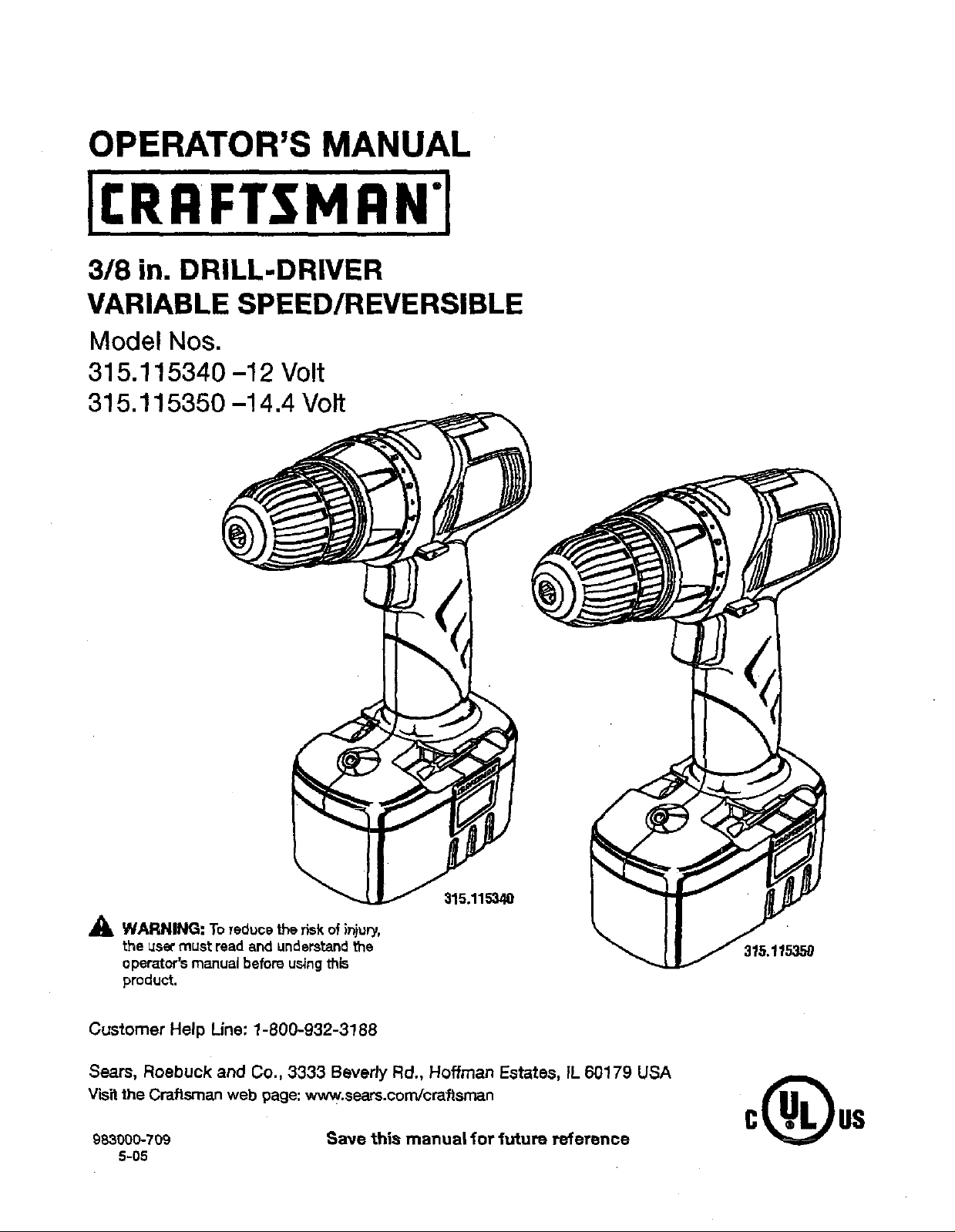
OPERATOR'S MANUAL
318 in. DRILL-DRIVER
VARIABLE SPEED/REVERSIBLE
Model Nos,
315.115340 -12 Volt
315,115350 -14,4 Volt
_, WARNING: To red_)cethe risk of in}ury,
the L_Se_must read and understandthe
operator'smanual before using this
product.
Customer Help Line: 1-800-932-3188
Sears, Roebuck and Co., 3333 Beverly Rd., Hoffman Estates, IL 60179 USA
V'_it the Craftsman web page: www.sears.com/craftsman
983000-709 Save this manual for future reference
5-05
Page 2
• Warranty .......................................................................................................................................................................... 2
• Introduction ......................................................................................................... ............................................................ 2
• GenaraJS_.fetyRules.................................................................................................................................................... 3-4
• Speciitc Sataty RuTes....................................................................................................................................................... 4
• Safety Rules for Charger .......................................................................................... ;...................................................... 5
== Symbols........................................................................................................................................................................ 6-7
• Features............................................................................................................................................................... _........8-9
• Assembly ......................................................................................................................................................................... 9
• Operation.................................................................................................................................................................. 10-15
• Maintenance............................................................................................................................................................. 16-17
• ExplodedView and Parts List................................................................................................................................... 18-1g
• Parts Ordering/Service .................................................................................................................................... Back Page
ONE YEAR FULL WARRANTY ON CRAFTSMAN TOOL
If thisCraftsman tool fails to give €omplate satisfactionwithinone year from date of purchase, RETURN IT TO THE
NEAREST SEARS STORE IN THE UNITED STATES, and Searswillreplace it, free of charge.
If thisCraftsman tool is used for cornmemialor rentalpurposes,this warranty appliesfor only90 daysfrom the date of
purchase.
This warranty gives you specificlegal fights, and you may also have other dghts which vary from state to state.
Sears, Roebuck and Co., Dept. 817 WA, Hoffman Estates, IL 60179
This tool has many features for making "¢.suse more pleasant and enjoyable.Safety, pertom_nce, and dependability
have been giventop priority in the designof this product makingit easy tomaintain and operate.
2
Page 3
WARNING!READANDUNDERSTANDALLIN-
STRUCTIONS. Failureto followall instructions§sted
belowmay result in electric shock, ('ireand/or sadous
personsi intury.
SAVE THESE INSTRUCTIONS
WORK AREA
• Keepyourwork ares clean sndwsll lit. Cluttered
benches and dark areas invite accidents`
• Do not operate power tools in explosive atmo-
spheres, such as in the presence of flammable liq-
ulde, gases, ordust. Power tools createsparkswhich
may igNte the dust or fumes.
• Keep bystanders, children, andvisitora awaywhile
operating a power tool. DislTactionscan cause you to
lose contm[.
ELECTRICAL SAFETY
• A battery operated tool with integral batteries or a
separate battery pack must be recharged onlywith
the specified charger for the battery, A chargerthat
may be suitablefor one type of batterymay create a
risk offirs when used with another battery.
• Use battery operated tool onlywlth epeclficaliy des-
ignated battery pack. Use of any otherbatteries may
create a riskof fire.
• Use battery only with charger listed.
MODEL
315.115340
315.115350 130139014 140302003
• Do not abuse the cord. Never use the cord to carry
the charger. Keep cord sway fl'om heat, oil, sharp
edges, or moving parts. Replace damaged cords
immediately, Damaged cords may create e fire.
PERSONAL SAFETY
• Stay alert, watch what you are doing and use com-
mon sense when operating • power tool. Do not
Use tool while f_redor under the Influence of drugs,
alcohol, or medication, A moment of inattentionwhile
operatingpowertools may resultin seriouspersonal
iniury.
• Dress properly. Do notwesr loose clothing or
jewelry. Contain long hair. Keep your heir, clothing,
end gloves away from moving parts. Looseclothes,
jewelry, or longhaircan be caughtinmovingparts.
• Avoid accidental starting. Be sure switch Is in the
looked or off position before inserting battery pack,
Carrying tools with yourfingeronthe switchor insert-
ingthe battery pack intoa too[with the switch on
invitesaccidentS.
• Remove adjusting keys or wrenches before turning
the tool on. A wrench or a keythat {s leftattached to a
rotating part of the tool may resultin personal in{ury.
BATTERYPACK CHARGER
130139017 140302002
ItemNo, P.11057 Item No._.1_055
Item No, _.11007 Item No..9.11006
• Do not overreach. Keep proper footing and balance
at all 5rues. Properfoo_ng and ba_nce enable be_er
cOnLTO[ofthe tool in unexpected situations.
• Use safety equipment. Nwaye wear eye protection.
Dust mask, non-skidsafetyshoes,hardhat, or hearing
protectionmust be usedfor appropriateconditions.
• Do notwear loose clothing or jewelry. Contain long
hair. Looseclothes,jewelry,or long haircan be drawn
intoah"vents.
• Do not use on a ladder or unstable support. Stable
tootingon a solid surface scabies better controlof the
too[in unexpectedsituatbns.
TOOL USE AND CARE
• Use damps or other pracfieal way to secure and
support the workplece to • stable platform. Holding
the work by hand or against your bodyis uns_ble and
may leadto Tossof con_'ol.
• Do not force tool. Use the correct tool for your ap-
plication. The correcttoo[willdo the job better and
safer at the rate forwhich itis designed.
• Do sot use tool if switch does not turn it on or off.
A tool that cannot be controlled with the switch is dan-
gerousand must be repaired.
• Disconnect battery pack from tool or place the
=witch in the locked or off position before making
any adjustments, changing accessories, orstoring
the tool. Such preventivesat'elymeasures reduce the
riskorst_'t_ngthetoo(aucident_iy.
• Store idle tools out of reach of ch|ldren and other
untrained persons. TooLsaredangerous inthe hands
of untrainedusers.
• When battery pack is not Jnuse, keep it away from
other metal objects like: paper clips, coins, keys,
nails, screws, or other small metal objects that can
make • connection from one terminal to another.
Shordngthe batteryterminals together may cause
sparks, bums, ora fire.
• Maintain tools with care. Keep cutting tools sharp
and clean. Properlymaintainedtoolswithsharp cut-
tingedges are less likely to bind and are easierto
control
• Check for mlsallgnment or binding of moving parts,
breakage of parts, and any other condition that
may affect the tool's operation. If damaged, have
the tool serviced before using. Many accidents are
caused by poorlymaintained tools.
• Use onlyaccessories that ere recommended by the
manufacturer for your model. Accessories that may
be sui_=blefor one too{ may create a risk of injurywhen
used on anothertoo[.
• Keep the tool end its handle dry, clean and free
from oil and grease, Alwaysuse a clean clothwhen
cleaning.Never use brake _uJds,gasoline,petrcleum-
based r_oducts,orany strongsolvents to oJeanyour
tool. Followingthis rule willreduce the risk of lossof
con_'oland deteriorationofthe enclosureplastic.
3
Page 4

SERVICE
• Tool service must be performed only by qualified
repair personnel. Serviceor maintenance performed
bYur_uaI_fisd per_nnel may resu{t {na risk of Inju_.
• When servicing e tool, use only Identical replace-
ment parts. Follow instructions in the Maintenance
section of this manual. Use of unauthorized partsor
bailumto I'ollcw Mainter_ance Instructions may create a
nskof shock oriniury.
• Hold tool by insulated gripping surfaces when
performing en operation whore the cutting tool may
contec_thidden _rlng. Contact with a "tire" wire wi_
also make exposed metal parts of the tool "live" and
shockthe operator.
• Know your power tool. Read operator's manual
carefully. Learn ito appnsetions and lirnltetione, as
well as the specific potential hazards rotated to this
tool. Followingthis rule willreduce the riskof electric
shock,fire, or seriousinjury.
• Always wear safety glasses with side shields.
Everyday glasses have only impaofresistant lenses.
They are NOT safety glasses. Followingthis rulewill
reducethe risk of eye il_ury.
• Battery tools do not have to be plugged into an
electTIcal outlet;,therefore, they ere always, In
operating condffion. Be aware of possible hazards
when not using your battery tool or when changing
accessories, Followingthis ru[ewill reduce the risk of
eIecbic shock, fire, or seriouspersonal iniury.
• Do not place battery tools or their batteries near
fire or heat. Thiswitlreduce the risk of explosionand
possib(yinjury,
• Never use a battery that has been dropped or
received a sharp blow. A damaged battery is subisc_
to explosion. Properlydispose of +tdropped or dam-
aged battery tmrnsdia1:e}y.
• Ballades vent hydrogen gas and can explode in
the presence of a source of Ignlfion, such ass pgot
light. To reduce _herisk ol serious personalinjury,
never useany cordtsssproductin the presenceof
open flame. An exploded batterycan propeldebde and
chemicals.If exposed,flush with water immediately.
• Do not charge battery tool in a damp or wet Ioce-
5o_. Fallowingthis rulewilt reduce the riskof electr_,
shock.
• For best results, your battery tool shou_ be
charged In a location where the temperature Is
more than 50°F but less than 100+i:,Do not store
outside or invehicles.
• Under exhume usage or temperature condi-
tions, battery I_aakags may occur. If liquid comes
In contact with your skin, wash Immediately with
soap and water, then ceutralize with lemon jules
or vinegar. If liquid gets into your eyes, flush them
wif_ clean water for at least 10 minutes, then seek
Immediate medical attention. Followingthisrulewill
reducethe risk of seriouspersonalInlury.
Page 5
'_ WARNING! READ AND UNDERSTAND ALL
INSTRUCTIONS. Failureto followall ins_'uctions
listed below, may result;in e]ecV_cshook, Tire
and(or seriouspersor_l injury.
• Before using battery charger, read all instructions
end cautionarymarkingsinthismanual, on battery
charger,battery, and produ_ usingbatteryto prevent
misuse of the productsand possibleinjury or damage.
_IL CAUTION." 3-oreduce the riskof electric shock
or damage to the chargerand battery,charge only
nickel-cadmiumrechargsable batteriesas specifi-
cell'/designated onyour charger.Other types of
batteries mayburst,causingpersonalinjury or
damage.
• Do not use charger outdoors or expose to wet or
damp conditions. Water enteringchargerwill increase
the riskof electricshock.
• Use ofan attachment not recommended or sold
by the batter,/charger manufacturer may result in
a risk of fire, electric shock, or in;_'ryto persons.
Followingthisrulewill reducethe riskof electric shock,
fire,or seriouspersonal iniury.
• Do not abuse cord or charger. Never usethe cord to
carrythe charger. Do notpull_hsshargsr cordrather
than the plugwhen disconnecting from receptacle.
Damage tothe cordorchmg_r couldoccurand create
an electric shockhazard, Replace damagedcordsim-
mediately.
• Make sure cord is located so that It will not be
stepped on, tripped over, come in contsct with
•sharp edges or moving parts or otherwise subject-
ed to damage or skess. Thiswill reduce the riskof
accidental fails, whish could causeinjury, and damage
to the cord, which could resultinelectric shook.
• Keep cord end charger from heat to prevent
damage to housing or internal parts.
• Do not let gasoline, oils, petroleum-based produ¢ts,
etc. come In €ontact with plastic parts. They contain
chemicalsthatcandmTmgs,weaken, or destroyplastic.
• An extsnston cord should not be used unless
absolutely necessary. Useof improper extensioncord
could resultin a riskof fireand electricshock, ff
extensioncord must be used, make sure:
a.That pins on plugofextension cord _re the
same number,sizeand shape as those of
plug on charger.
b. That extensioncord is properlywired and in
good etect_cat condition;and
c. That wire size is large enoughfor AC ampere
ratingof chargeras specifiedbelow;
Cord Length {Feet) 25' 50' 100'
Cord Size (AWG) 16 16 16
HOTII="AWG = AmericanWire Gauge
• Do not operate charger with a damaged cord or
plug,which €ould causeshoKmgand e{ectr_ shook.If
darnaoed, he_e thech_ger tegk_ced by an Buth_rized
servioem&n,
• Do not operate charger if ithas received a sharp
blow, been dropped, or othermdsedamaged in any
way. Take it to an authorized servicemanfor eiectlicat
checkto determine if the chargeris in goodworking
order.
Do not disassemble charger. Take it to an authorized
servicemanwhen serviceor repairis required. Incor-
rect reassomblymay result in a riskof electricshookor
fire,
• Unplug charger from outlet before attempting any
m_dnte_nce or _isaning to reduce the risk of
elecbio shock.
• Disconnect charger from the power supply when
not in use. This willreduce the dsk of electric shock
ordamage to the chargerif metal items shouMf_ into
the opening.It also willhelp preventdamageto the
charger dunng a powersurge.
• Risk of electric shock. Do not touch uninsolated
portionof outputconnector or uninsuistedbattery
terminal.
• Save these instructions. Referto them frequentJyand
usethem to lnstruct otherswho may use this tool If
you loan someonethis tool, loan them these instruc-
tions alsoto preventmisuseof the productand
possible Injury.
_k WARNING: Some dust created by power sending,sawing, grinding,drilling, and otherconstructionactivities
containschemicalsknownto cause cancer,birth defects or otherreproductiveharm. Some examplesof these
them{catsare:
• _cadJrom_ead-basedpalnhs,
=crystanlne silicafrom bricks and cementand othermasonryproducts,and
• arsenic and chromiumfrom chemically-treated lumbar.
Yourriskfrom theseexposures varies,depending on how ot_snyou do this type ofwork. Toreduceyour exposure
tc these chemicals: work in a we_lvantiistedarea,and work with approved safety equipment,suchas those dust
masks that are speciallydesignedto filterout microscopicparticles.
5
Page 6
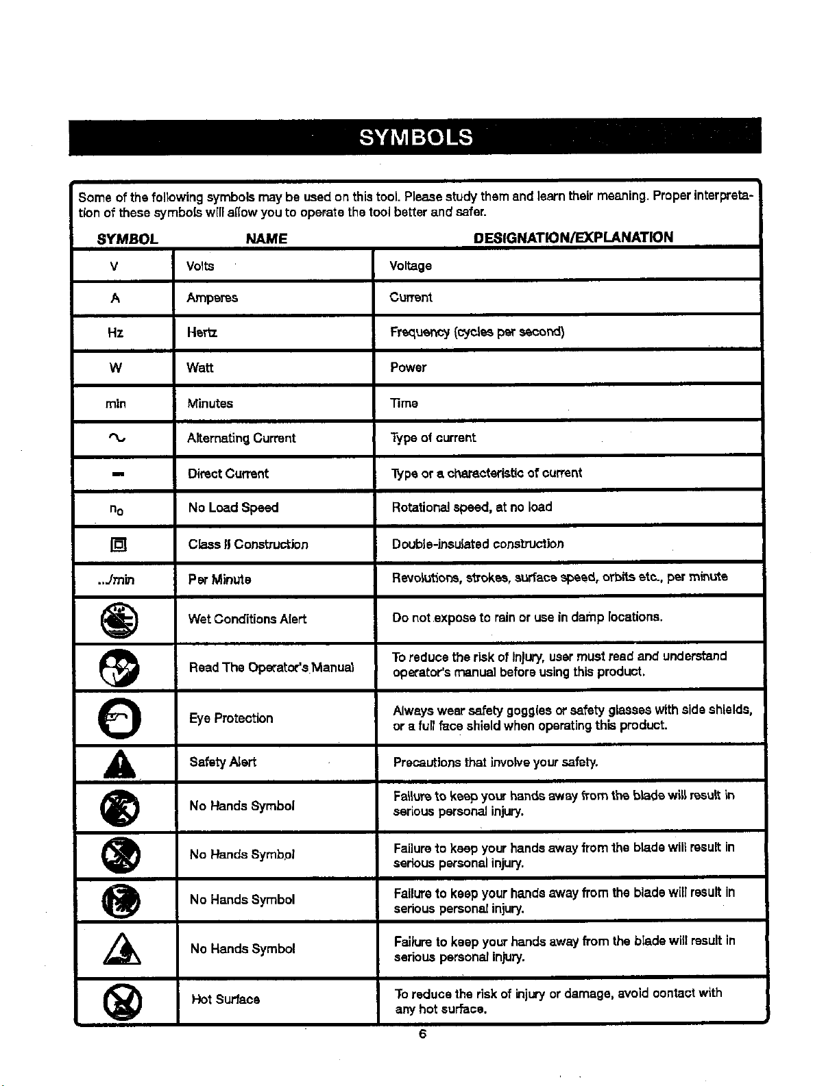
Some of the following symbolsmay be used on thistool. Please studythemend learntheirmeaning. Properinterpreta-
tionof these symbolswfl[allow youto operate the tool better and safer.
SYMBOL NAME DESIGNATION/EXPLANATION
V Volts Voltage
A Amperss Current
Hz Her_. Frequency (cycles per second)
W Watt Power
min Minutes Time
AlterrmtingCurrent Type ofcurrent
-. Direct Current "[ypeor a characteristicof current
no No Load Speed Rotationalspeed, at no load
[] Class I! Construction Double-insulated construction
..Jmin Per Minute Revolutions,strokes,surfacespeed, orbitseta., per mince
Wet ConditionsAlert Do not expose to rainoruse indamp locations.
Read The Operator's Manual operator'smanual before usingthis product.
Eye
Protection Alwayswear safety gogg(esorsafety glasseswithsideshields,
_IL Safety Alert Precautionsthat invotve safety.
_) Fal_umto keep your handsawsy from the bk-_dewitt result In
_) No Hands Failure to keep your hands away from the blade will result in
_) No Hands Symbol Failure to keep your hands away from the blade will result in
(_) Hot Surface Toreduce the dsk of injuryordamage, avoid oontactwith
No Hands Symbol serious personal injury.
Symbol
No Hands Failureto keep yourhands away from theblade will resultin
Symbol
To reduce the risk ofInjury, usermustread and understand
or a full face shieldwhen operatingthis product.
your
serious personal injury.
seriouspersonal injury.
seriouspersonaJinjury.
any hotsurface.
6
Page 7

Thefollowing signalwordsand meaningsare intendecLto expl_n the levels of riskassociated with this
product.
SYMBOL SIGNAL MEANING
DANGER:
_k WARNING:
CAUTION:
CAUTION:
SERVICE
Servicingrequires extremecare and knowledgeand
shouldbe performedonlybya qualified servicetech-
nician.For service we suggestyoureturnthe productto
your nearest AUTHORIZED SERVICE CENTER for
repair.When servicing, useonlyidentioalreptacement
parts.
_,WARNING:
The operationofany powertoolcan resultin foreign objects beingthrown into youreyes, which
c_n result in severeeye damage. Beforebeginningpowertool operation,alwayswear safetygog-
O
gles or safety glasseswith sideShields,or a full face shieldwhen needed.We recommendWide
VisionSaFetyMask for Hssovereyeglasses or standardsafety gl_sses with side shielc_s,Always
use eye protection which is marked to complywith ANSI Z87.1.
Indicates an imminentlyhazardous situation,which, ff not avoided,will
resultin death or seriousinjury.
Indicates a potentiallyhazardoussituation, which, ff not avoided, could
resultindeathorseriousinjury.
indicates a potantialtyhazardoussituation,which,if notavoided, rnay
resuffin minor or moderate injury.
(WithoutSafetyAlert SyrnboDIndicates a situationthat may result in
propertydamage.
_, WARNING: To m/oid seriousparsons1 injury,do not
attempt to usethis productuntilyou read thoroughly
and understandcompletelythe operator'smanual
Save thisoperator'smanual and review fTequentlyfor
contLnuingsaia operatior_and instructing oth_rswho
may usethisproduct.
SAVE THESE INSTRUCTIONS
7
Page 8

PRODUCTSPECIFICATIONS
MODELNO.315.t15340
Chuck .......................................................... 3/8 in. Keyless
Motor .................................................................. 12Volt DC
Switch.......................................................... VariableSpeed
No Load Speed ................................................. 0-600/rain.
Clutch................................................................ 24 Position
Torque.................................................. Maximum100 in.lb.
Charger Pnput................................... 120 V, 60 HT_,AC only
Charge Rate ............................................................ 3 hours
TORQUE LEVEL
ADJUSTMENTRQ_G
MODEL NO. 3t5.t15350
Chuck .......................................................... 3/8 in. Ksyles=
Motor.................................................................. 14 Volt DC
Switch.......................................................... VariableSpeed
No Load Speed ................................................. 0-600/min.
Clutoh.......:........................................................ 24 Position
Torque.................................................. Maximum 110 in.lb.
Chargerhput ................................... 120 V,60 Hz, AC only
Charge Rate ............................................... _............3 hours
KEYLESS
CHUCK
LED
WORKLIGHT
BATTERYPACK
SWITCH
TR(GGER
DIRECTIONOF
SELECTOR
(FORWARD)REVERSE]
CENTERLOCK)
CHARGER
SCREWDRIVER
BITS
BITSTORAGE
REDLED
ORANGELED Fig. 1
8
Page 9

KNOWYOURDRILL-DRIVER
See Figure 1.
Beforeattemptingto usethisproduct,familiarizeyourself
with alloperating featuresand safety rules.
BIT STORAGE
Bits provided with thedrill-drivercan be placed inthe
storagearea, located on the base of the drill.
DIRECTION OF ROTATION SELECTOR
(FORWARD/REVERSE/CENTER LOCK)
Yourdrill-driverhasa directionof rotation(forward/reverss/
centei"lock) selector located above the switch _ggar for
changing the direction of bit rotation. Setting the switch
trigger in the OFF (center lock) position helps reduce the
possibilityof accidentalstartingwhen notin use.
KEYLESS CHUCK
"mekeylass chuck allows you to hand-tightenor release
the drill bit inthe chuckjaws.
LED WQRKLIGHT
The LEDworPJight,located onthe front of the toolbase,
illuminateswhen theswitch_'iggar ts depressed.This
providesextra light for inoreased yisibility.
LEVEL
A level islocated on the top of the motor housingto help
you keepthe drillbitlevel duringuse;
TORQUE AI0klMSTMENT RING
Yourdrill-driverhasa 24-position clutch.The torque
adjustment ring can be turnedto selectthe rightamount
of torque for your application.
VARIABLE SPEED
The variablespeed switchtriggar delivers higher speed
with increasedttlgger pressureand lower speed with de-
,teased triggerpressure.
UNPACKING
This producthas been shippedeompiatslyassembled.
• Carefulfyremovethe tool and any accessoriesfTomthe
box. Make surethat a_litemslisted in the packing list
are included.
• Inspectthe too[ carefullyto make sure no breakage or
damage occurred dunngshipping.
• Do not discard the packingmaterialuntilyou have
carefullyinspected and setistactoril¥ operatedthe tool.
• If any partsare damagedor missing, please call
1-800-932-3188 for ase'_tance.
PACKING UST
Drill-Driver
Battery Pack (2)
Charger
Double-ended Bits(2I
CarryingCase
Operator's Manual
,P=
41L WARNING: If anyparts are missingdo not operate
thistool untilthe missingparts arereplaced.Failure
to do socould resultin possibleseriouspersonal
injury.
A
WARNING: Do not attemptto modify thistool
or createaccessories not recommendedfor use
with this tool. Anysuch alterationor modification is
misuse arid coutdresul_in s h_.ardous condition
leadingto possibleseriouspersonalir(|ury.
_1_ WARNING: To preventaccidentalstartingthat
could cause seriouspersenaf injury, a_,ays remove
the battery pack _om the too[ when assembling
parts.
Page 10

_1_ WARNING: Do not allowfamiSa_tywith tools to
make you careJess.Rememberthat a careless
fracbonof a second is sufficientto intiictserious
]njury.
_k WARNING: Alwayswear safety gogglesor safety
glasseswith side shieldswhen operatingtools.
Failureto do so could resultinobjectsbeingthrown
intoyour eyes,resultinginpoasibisseriousinjury.
_1= WARNING: Do not useany attachments or acoas-
series not recommended by th_rna_u_oturer of
this tool.The use ofattachmentsoraccessories not
recommended can resultinserlouspersonalinjury.
APPLICATIONS
You may usethistoolfor the foUowingpurposes:
• Drillinginwood
• Drillinginceramics, plastics,fibergtess,and laminates
• Ddlling in metals
• Mbdngpaint
CAUTION: If at any point duringthe charging
processnone ofthe LEDs are lit, removethe bat-
tary pack _'om _e chargerto avoiddamaging the
product. DO NOT insertanother battery.Return the
charger and battery toyour nearestservicecenter
for service or replacement.
CHARGING THE BAI-I'ERY PACK
The battery pack for this tool has been shippedin a low
charge conditionto preventpossible problems.Therefore,
you shouldcharge overnightpriorto use.
NOTE: Batterieswill not reach furl oharge the first time
theyare charged. Allow several cycles(operationfollowed
byrecharging]for them to become fully charged.
• Charge battery packonlyw_ththe charging assembly
provided.
• Make sure power supply is normalhouseholdvoltage,
120 volts,60 Hz,AC on_y.
• Connect charger to power supply.
• Place battery pack in charging stand.Align raiseddb
on bat_eP/pack with groovein chargingstan_. See
F/gum 2.
• Pressdown on b_ttsrypack to be'sure contacts on
battery pack engageproperlywith contacts in charging
stand.
• The chargeindicator light (LED), locatedon the charg-
ing stand, wi_I'_ghtup red and glowwhenthe eharger
is properlyconnectedto power supply."Thislight
indicates thecharger is operatingproperty.It will
remainon unblbatterypackis removedfrom charging
stand or charger is disconnectedf_om powersupply.
• After normaJusage,3 hoursork_saof chargingtime is
required to hJftyrecharge battery pack.
NOTE; If bothredand orangeLED ind_caforsglow, the
battery pack isdeeplyorcompk=.te0jd(scharged, and
6 hours er longerof chargingtime }s requiredto fully
rechargethebatterypack,
Ifthechargerdoesnotcharge_hebatterypack,or
the orangeLED corr_nuesto glowafter more than 30
m_nutesof chsrg'lng,returnthe battery pack andcharg-
inge.ssemb[yto yournearestSears Repair Center for
electricalcheck.
• The batterypackwill become slightlywarm tothe
touch while charging.This is normaland does not
indicate a problem.
m Do not place chargerin an area of extreme heat or
cold. It wiltwork best at normalroom temperature.
II When batteriesbecome fully charged, unplugcharger
from power supply and removethe battery pack.
CHARGING A HOT BA'rrt=RY PACK
When usingyour tool continuously, the batteries Inyour
battery pack will become hot.Youshould let a hotbattery
pack cool down for approximately 30 minutesbefore
attempting to recharge.
NOTE: This situationorgyoccurswhen continuoususe of
your ddll causes the batteriesto become hot. It does not
occur under nonT_ circumstances.Refer to =CHARGING
THE BATTERY PACI_ for normalrecharg]ngofbattedes.
Ifthe chargingaasembly doesnot chargeyour battery
pack undernormalcircumstances,returnboth the battery
pack and chargingassembly to your nearest Sears Repair
Center for electricalcheck.
10
Page 11

BATTERYPACK
SHOWNINCHARGER CI'.I_GING
REDLED
ORANGELED
TO INSTALL BATTERY PACK
See FTgure3.
• Lockthe switch trigger on the drillby placingthe direc-
t(on ofrotation selectorin the center position.
• Place the battery pack in the ddlLAlignthe raisedrib
onthe bakery pack wtth the grooveInsidethe drill
ASSEMBLY
CHARGINGSTAND
Fig. 2
TOREMOVEBATTERYPACK
See Figure3.
• Lockthe switchtriggeran the drill by placingthe direc-
tion ofrotationselectorinthe center position.
• Locate the latcheson the side ofthe batterypack and
depressto releasethe batterypack fTomthe drill.
• Remove the battery pack from the drill.
LATCHES
CAUTION: When placing baC_terypaeY,_nthetool,
be sure raisedrib on battery packalignswiththe
bottom of the ddlland latchesintoplacepropedy.
Improper installationofthe battery packcan _use
damage to internalcomponents.
• Make surethe latches on each side of the batterypack
snap into place and the battery pack issecwed inthe
dd[{before beginningoperation.
DEPRESSUITCHESTO
RELEASEBAT'rERYPACK
F_g.3
11
Page 12

A
WARNING: 6artery tools are a(ways in operatirtg
conditfon. Therefore, the switch should always be
locP.ed when not in use or carrying at you_"side.
Avoidrunningthe drll_at low speeds for extswdedperiods
of Lime.Runningat low speeds under constantusagemay
causethe drillto become overheated. Ifthis occurs, cool
the drillby runningit withouta loadand at full speed.
SWITCH TRIGGER
See Rgure 4.
To turnthe driJlON, depressthe switch trigger.To turnit
OFF, release the switchtrigger.
VARIABLE SPEED
See F/gum 4.
The variable speed switch triggerdelivers higher spee(J
and torque wi_ increased _gger pressureand lower
speed with decreased trigger pressure.
NOTE= Youmight heara whistlingor ringingnoisefrom
the switchduringuse.Do not be concerned; this isa nor-
mal part of theswitch function.
DIRECTIONOF
HOTA'I"[ONSELECTOR
(FORWARD/ REVERSE
/ _ LOCK)
REVERSE
VARIABLESPEED
SWITCHTRIGGER
KEYLESS CHUCK
See Figure5.
The drin-driverhas a keytese chuck to tightenorrelease
dd[[bitsin the chuckjaws. Grasp and holdthe collarof
the chuckwlth one hand. Rotate the chuck bodywith your
other hand.The arrows onthe chuck indicatewhichdirec-
tionto rotate the chuck body inorder to LOCK (tighten)or
UNLOCK (release)the dr_UbiL
dl_ WARNING: Do not holdthe chuck body with one
handand usethe powerof the dn'llto tightenthe
chuckjaws on the dd]]bit. The chuck body could slip
inyourhand, or your handcouldsI_pand come in
contact with the rotatingdrtnbit.This couldcause an
accidentresultingin seriouspersonalInjury.
UNLOCK
DRILLBIT (RELEASE)
!
FORWARD Fig. 4
FORWARD/REVERSE/CENTER LOCK
See FTgure4.
"['hedirectionof bit rotation isreversibleand is controlled
by a selector locatedabove the switchtrigger. With the
driftheld innom_aloperatingposition,the directionof
rotationselector shou[d be positionedto the leftof the
switch triggerfor drilling.The ddflingdirectionisreversed
when the selector isto the rightot theswitcht_gger.
Setting the switch trigger in the OFF (car_erlook) position
helpsreduce the possibilityofaccidental startingwhen not
inuse.
CAUTION: To prevent gear damage, alwaysallow
the chuckto come to a complete stop beforechang-
ingthe directionof rotation.
To stop the drill,releasethe switch triggerand allow the
chuck Locome to a complete stop.
NOTE: The drillwillnot run unlessthe directionof rotation
selector is pushedfully to the leftorright.
JAWS
LOCI(
(TIGHTEN) CHUCK
BODY
Flg"5
12
Page 13

ADJUSTABLE TORQUE CLUTCH
The drillls equipped withanadjustabletorqueclutchfor
drivingdifferenttypes of screws into differentmaterials.
The proper setting dependson the type ofmaterial and
the size of sorewyouare using.
ADJUSTING TORQUE
See Ftgure6.
• There are Lwenty-fourtorque indicatorsettings located
on the _TO_ofthe drill.
• Rotate the adjusting ringto the desiredsetting.
• 1- 4 Fordrivingsmed[screws
• 5 - 8 Fordrivingscrews intosoft
materia_
• g - 12 For ddving screws into softand hard
materials
• 13 - 16 For drivingscrews into hardwood
=17 - 23 Fordriving large screws
• 4U Forheavy drifting
TODECREASE ADJUSTING
TORQUE R/NO
LED WORKLIGHT
See F/gum 7.
The LEDworkJightonthe foot of thedrillwill come on
when theswitch _'igger iedepressed.This providesaddi-
tional lightingon the surfaceof the workpieoefor opera-
Lionin lower-lightareas.
LED
WORKLIGHT
TOIXCREASE
TORQUE _,
Fig. 6
Fig. 7
Bff STORAGE
See Figure8.
When not in use, bits providedwiththe drill can be placed
int_e storagearea located on the base of the driU.
SCREWDRIVERBIT(S)
\
BIT
AREA
13
Page 14

INSTALLING BITS
F/gure 9.
• Lock the switchtrigger by piecing the direction of rota-
tion selector in the center position.
• Open or close the chuckj_zwsto a pointwhere the
openingLsalight/largar then the bit elzeyou intend to
use. Also, raisethe front of the driftstighttytokeep the
b_ from fa_lingoutof the chuckjaws.
• Insertthe drillbit straightinto the chuckthe full length
ofthe jaws.
• Tighten the chuck jaws onthe drillbit.
DRILLBIT UNLOCK
. (RELEAEE)
CHUCK
COLLAR
LOCK
(TIGHTEN)
CHUCK
BODY
RIGHT Fig. 9
• TOtighten: grasp and hold the collarof the chuck with
one hand,while ro'_ting the chuck body with your
otherhand.
NOTE: Rotate the chuck body inthe directionofthe
arrow marked LOCK to tighten the chuckjaws.
• Do not usea wrench to tighten or loosenthe chuck
ja.w8.
_k WARNING: Make sure to insertthe drillbit straight
intothe chuckjaws. Do not insertthe drillbit into
the chuckjaws at an angle then tighten, as shownin
figure1O.Thls could causethe drillbit to bethrown
from the drill,resultingin possib]e seriouspersonal
injuryor damageto the chuck.
WRONG Fig.10
REMOVING BITS
See F_jure g.
• Lock the sw(tch t_gar by placing the directionof rota-
tion selector inthe center position.
• Loosenthe chuckjaws from the drillbiL
• To loosen:grasp and hold the collar of the chuckwith
one hand,while ro_ting the chuck body with your
other hand.
NOTE: Rotatethe chuck bodyinthe directionat the
arrow ma_sd UNLOCK to loosenthe chuckjaws.
• Do not use a wrench to tightenor loosenthe chuck
jaws.
• Remove the driftbit from the chuckjaws.
14
Page 15

'_ WARNING: Alwayswsar safety goggles orsafety
glasseswith aide shieldswhen operatingtools.Fail-
ureto do so could resultin objectsbeing throwninto
youreyes, resultingin possibleseriousinjury.
DRILLING
See Figure 11.
A levelis located on top of themotor housing to help keep
thedrill bit levelduringuse.
• Check the directionof rotationselector for the correct
sathng (forward orraverae).
• Secure the material to be drilledin a vise orwith
clampsto keep_t'{Tomturningasthe ddlt bit rc>_atas.
• Hold the drillfirmlyand place thebit at the pointto be
• Depress the switch trigger tostart the drill.
• Move the drillbitintothe work,piece, applying only
enough_ress_e to keep the bit cuthng.Do not toms
the dritiorapphj sidepressure'coelongatea hole. Let
the tool do the work.
_lk WARNING: Be prepaxsd for binding a_bit break-
through.When thesesituationsoccur,drillhas a
tendencyto grab and kick oppositeto the direction
of rotationand couldcause loss ot control when
breakingthroughmaterial. )1'not prepared,this loss
of controlcan result inpossibleseriousin(ury:.
LEWL
F_g.tl
• When drillinghard,smoothsurfaces, usea center
punchto mark the desired hole location. Thiswillpre-
vent the dn'ilbit from slippingoff-centeras the holeis
started.
• When drillingmetals, use a light oil on the drill bit to
keep it from overheating.The oilwillprolong the life ot
the bitand increase _e driltingaction.
• If the bit )aresin the workpiecaor itthe ddllstalls,
stop the tool irnmed_tel'/. Remove the bit from the
workpiece and determinethe reasonforjamming.
Thisdrillhas an elecb'Jobrake. Whenthe switch trigger
isreleased, the chuckstops turning,Whenthe brake is
functioning properly,sparkswill be visiblethroughthe
ventslots on the housing.This is normaland is the action
ofthe brake.
15
Page 16

_I_ WARNING: When servicing, use on3yidentical
Craftsman replar.smentparts. Use ofany otherpaTt
may create a hazard or cause product damage.
_k WARN|NG: Alwayswear safety gogglesor safety
gta.sesswith side shieldswhen usingcompressed air
to clean tools. ITthe operationis dusty,siso wear a
dust mask.
_lk WARNING: To avoid seriouspersonalinjury,always
remove thebattery pack from the tool when cleaning
or performingany maintenance.
G ENERAL MAINTENANCE
Avoid usingsolventswhen cleaning plasticparts. Most
plasticsare susceptibleto damage fromvarioustypes st
commemia] solventsand may be damaged by their use.
Use clean cloths to remove dirt, dust, sit, grease, eta.
_1_ WARNING: Do not at any time let brake fluids,
gasoline,petroleum-based products, penetrating
oils,etc. come ]ncon'_ct with plasticparts. Chsmi-
Palscan damage, weaken or destroy plasticwhich
may resultin serious personalinjury.
CHUCK REMOVAL
See F-_ums 12- 14.
The chuci(maybe removedand replaced bye new one.
• Lock the switch triggerby placingthe directionof rota-
tion selector incenter position.
• |nsert a 5116 in.orlarger hex key intothechuck of the
driUarid tighten the chuck jaws securely.
• Tap the boxkey sharplywith a ma[(etina clockwise
direc_on. This w|_loosenthe scrs_, _nthe ohucY,tot
easy removal
Only the parts shown on the parts [(stareintended to be
repairedor rep(acedby the customer.All other parts
should be replaced at a Sears ServiceCenter.
KEYt,.ESS
CHUCK
Fig. "t2
• Open the chuck jaws and remove the hsx key. Usinga
scrawdriver,remove the chuck screw by b._'ningit in a
clockwisedirection.
NOTE: The screw hasleft handthreads.
SCREWDRIVER
Fig.13
16
Page 17

• Insert the hex key into the chuck and tighten thechuck
jaws sacurety.Tap sharplywith a m_et in a counter-
clockwise d_rection.Thiswilt loosenthe chuck onthe
spindle. It can now be unscrewedby hand.
N_-_ET
Fig. 14
TO RETIGHTEN A LOOSE CHUCK
l'ha chuck may become looseonthespindleanddevelop
a wobble. Periodicallycheck the chuck.screwfor tight-
ne_s.
• Lock the switchtriggerby placingthe directiono! rota-
tionselector in the canter position.
• Open the chuck iaws.
• insert the hex key intothe chuck and _ghten the chuck
jaws sscurel'/."Tapthe hex key sharplyw_h a mallet in
a clockwisedirection.Thiswilltightenthe chuck on the
spindle.
• Open the chuck jaws and removethe hax key.
• Tighten the chuck screw.
NOTE: The chuck screw has left handthreads.
BA'rrERIES
The batterypack for this tool isequipped with nickel-cad-
mium rechargeabiebatteries. Lengthof servicefrom each
chargingwilldepend onthe type ofworkyou are doing.
The batteriesin this tool have been designed10provide
maximum b-ouble-frselife. However,llke all batteries, they
w[UevantusllywearouL Do not disassemblebattery pack
and attempt to replace the batteries.H_ndtingof these
batteries, especiallywhen wearingringsand jewelry,could
resultina serious burn.
To obtain thelongestpossible battery life, we suggestthe
foUoWing:
• Removethe batterypack from the chargeronce it is
futly chargedand ready for use.
For battery pack storagelonger than 30 days:
• Store thebattery pack where the temperature isbelow
80°F.
• Store battery packs in a "discharged" condition.
BATTERY PACK REMOVAL AND
PREPARATION FOR RECYCLING
To preservenaturalresources,please
mcyc_ ordispose of t_tteries
properly.
ThLsproductcontains nickel-cadmium
batteries, Local,state or federal
lawsmay prohibitdisposal of nickel-
cadmiumbatteries inordinaryb'esh.
Consultyour local waste authority for information
regardingavailab[e recyclingand/or c_ispoea(options.
_k wARNING: Upon removal,cover the battery pack's
terminalswith heaw-duty adhesivetape, Do net
attempt to destroy or disessemb_eb_tary pack or
removeany ofits components. Nickel-cadmium
batteriesmust be recycled or d(spossd of properly.
Also, nevertouchboth terminalswith metal objects
andJor body p_'ts as short circuitmay result.Keep
away fromc_ldren. Failureto comply with these
warnings could result in fire and/or serious injury.
17
Page 18

_- CRAFTSMAN 12 VOLT DRILL-DRIVER - MODEL NUMBER 315,115,340 -.----.---
ii
number [nallcorrespondenceregardingyourDRILL-DRIVER orwhen orderingrepairparts,
The model number w([[ ba found on a platsattachedtothemotorhousing.Alwaysmentionthemodel |
SEE BACK PAGE FOR PARTS ORDERING INSTRUCTIONS
2
1
\
J
Key Part
No. Number
1 6612001
2 6903326
3 9,;0237076
4 140302002
5 130139017
6 300912192
983000709
4
5
\
PARTS LIST
DesQription Qty.
Chuck Screw ..............................................................................................I
Chuck ......................................................................................................... 1
Data Plate .................................................................................................. 1
* Charger (Item No, _tl 1057).......................................................................... 1
* Battery Pack (Item No. _-11055}.................................................................. 2
CarryingCase (Not Shown) ........................................................................ 1
Operator's Manual
• Can Be Purchased Thru RSOS (Retail Special Order System)
18
Page 19

CRAFTSMAN 14A VOLT DRILL-DRIVER - MODEL NUMBER 315.1t5350
number in artcorrespondence regardingyour DRILL-DRIVER or when ordering repairparts.
J The model number will befound on a plate attached to the motor housing.Always mention the model |
SEE BACK PAGE FOR PARTS ORDERING INSTRUCTIONS
2
1
\
I
Key Part
No. Number
1 6612001
2 6903326
3 940237074
4 140302003
5 13O139014
6 300912193
983000709
5
\
PARTS LIST
Oescription Qty.
Chuck Screw ............................................ .................................................. 1
Chuck ......................................................................................................... 1
Data Plate................................................................................................... 1
"Charger (Item No. _.110C_).......................................................................... 1
"Battery Pack _ltem No. 211007) .................................................................. 2
Carrying Case (Not Shown)........................................................................ 1
Operator's Manual
* Can Be Purch=sed Thru RSOS (Fletail Special Order System)
19
Page 20

Your Home
For repair-in your home-of all major brand appliances,
lawn and garden equipment, or heating and cooling systems,
no matter who made it, no matter who sold PJ
For the replacement parts, accessories and
owner's manuals that you need to do-it-yourself.
For Sears professionalinstallationof home appliances
and items like garage door openers and water heaters.
1-800-4-MY-HOME ® (l-_o-4ss-4ss3)
Call any'dine, clay or night (U.S.A. and Canada)
www.sears.com www,seal_.Ca
ill
Our Home
For repair of carry-in itemslike vacuums, lawn equipment,
and electronics, call or go on-line for the location of your nearest
Sears Parts & Repair Center.
1-800-488-1222
Call any6me, day or night (U.S J_. only)
www_rs.co111
To purchasea protectionagreement(U.S.A.)
ormaintenanceagreement(Canada)on a productservicedbySears:
1-800-827-6655 (u.s.A_) 1-800-361-6665 (Canada)
PaPa pedir servicio de reparacibn
a domici5o, y para ordanar piezas:
1-888-SU-HOGAR =
(1-888-784-6427)
_ Registmed Trademark I _ Trademark I _ _x,/icQ V_rk of Seres, Roe_jck and _.
0 Mar_ P_ada I'm Marca de F_txlca I su Marca de Seriic]o de Sears, Roobuck a_ _.
r'_ Mar_pJe do €o_mrcQ I _mI_ d6pos_ de Serum, Roebuck er_l Co. © seam, Roebuck and CO.
Au Canada pour service en frontals:
1-800-LE-FOYER _c
O-soo-s33-s_7)
_.seal_.Ca
 Loading...