

Page 1

Save This Manual For
Future Reference
SEAMS
owners
manual
MODEL NO.
113.299780
Dust Collection
System
Serial
Number
Model and serial number may be
found on the motor cover.
You should record bottn model and
serial number in a safe place for
future use.
FOR YOUR
SAFETY:
READ ALL
INSTRUCTIONS
CAREFULLY.
mms
EiiPfSMii
DUST COLLECTION
SYSTEM
• assembly
• operation
• repair parts
V.
Sold by SEARS, ROEBUCK AND CO., Chicago, !L. 60684 U.S.A.
Part No. SP5373 Printed in Taiwan
J
Page 2

FULL ONE YEAR WARRANTY ON CRAFTSMAN DÖST COLLECTION SYSTEM
If within one year from the date of purchase, this Craftsman Dust Collection System fails due to a defect in
material or workmanship, Sears will repair it, free of charge.
WARRANTY SERVICE IS AVAILABLE BY SIMPLY CONTACTING THE NEAREST SEARS SERVICE CENTER/
DEPAffMEI^t THROUGHOUT THE UNITED STATES.
This warranty applies only while this product is used In the United States.
This warranty gives you specific legal rights, and you mayalso have otherrights which vary from state to state.
SEARS, ROEBUCK AND CO., D/817 WA HOFFMAN ESTATES, IL 60135
IMPORTANT SAFETY INSTRUCTIONS
When using your Dust Collection System, follow basic
safety precautions including the following.
WARNING a To reduce the risk of
fire, electric shock, or Injury:
• Read and understand this owner’s manual and all
labels on the Dust Collection System before oper
ating, Use only as described In this manual. To
avoid personal injury or damage to Dust Collec
tion System, use only Sears Craftsman recom
mended aCcesSbries.
Sparks inside the etectricai parts, can ignite flammable
vapors or dust. To avoid fire or explosion;
• Do not vacuum, or use this Dust Collection System
near flammable or combustible liquids, gases, gaso
line or other fuels, lighter fluid, cleaners, oil-based
paints, natural gas, hydrogen, or explosive dusts like
coal dust, magnesium dust, grain dust, orgun powder.
• Do not vacuum anything that is burning or smoking,
such as cigarettes, matches, or hot ashes.
• To avoid health hazards from vapors or dusts, do not
vacuum toxic materials.
• To avoid injury from accidental starting, unplug power
cord before changing or cleaning filter/dust bag or chip
bag.
• Do not use without filter/dust bag and/or chip bag in
place.
• Do not unplug by pulling on cord. To unplug, grasp the
plug, not the cord.
• Turn off controls before unplugging.
• Do not use with damaged cord, plug or other parts. If
your Dust Collection System is not working as it
should, has missing parts, has been dropped, dam
aged, left outdoors, or dropped into water, return it to
a Sears Service Center.
• Do not pui! or carry by cord, use cord as handle, close
a door on cord, or puli cord around sharp edges or
corners. Do not run Dust Collection System overcord.
Keep cord away from heated surfaces.
• Do not handle plug of the Dust Collection System with
wet hands.
* Do not use dr store near hazardous materials.
* Do not use outdoors or on wet surfaces,
• Put unit on a stable, level surface.
• Route vacuum hose and electric cord out of traffic
areas.
♦ Do not allow to be used as a toy. Close attention is
necessary when used by or near children.
• Dohbt ieave appliarice plupeci in. Unplug from outlet
when not in use a;nd before servicing.
SAVE THESE !NSTRUCT!ONS
• Do not put any object into ventilation openings. Do not
vacuum with any ventilation openings blocked; keep
tree of dust, lint, hair or anything that may reduce air
flow.
• Keep hair, loose clothing, fingers, and all parts of body
away from openings and moving parts.
• Extension cords in poor condition or that are too small
can pose fire and shock hazards. When using an
extension cord, be sure It is in good condition. See
"Extension Cords" in the "Operation" section torproper
wire sizes.
• Connect to properly grounded outlet only. (See
"Grounding Instructions" on page 14.)
Page 3

Aa CAUTION: if using this Dust Collection System
to help keep airborne wood dust in heavy usage
within acceptable limits, you must regularly monitor
air borne dust and maintain Dust Collection System
to avoid exceeding dust limits. Each application is
unique. Your maintenance schedule must, there
fore, be tailored to your specific use of this Dust Col
lection System.
Safety is a combination of common sense, staying alert
and knowing how your Dust Collection System works.
BEFORE USING THE DUST COLLECTION
SYSTEM:
A
WARN ING: TO AVOID MISTAKES TH AT COU LD
RESULT IN SERIOUS, PERMANENT INJURY, DO
NOT CONNECT POWER CORD UNTIL THE FOL
LOWING STEPS HAVE BEEN SATISFACTORILY
COMPLETED:
1. Assembly, mounting and alignment.
2. Learn the function and proper use of the ON-OFF
switch.
3. Read and understand all safely instructions and
operating procedures throughout the manual.
4. Read the following labels which appear on the top
and bottom of filtration housing and sides of motor.
AWARNING
Metal shavings or dust can set
sawdust on tire.
Collect wood materials only.
Do not collect metal shavings
or dus!.
See manual for délai 1 s.
Risk of electrical shock.
Use indoors in dry area.
Do not use outdoors or on wet
surfaces.
BEFORE EACH USE:
1. Inspect your Dust Collection System. If any parts
are missing, bent, or tail in any way. or any electri
cal components do not work properly, turn off the
Dust Collection System, remove switch key, and
remove power supply cord from power supply.
Replace damaged, missing or failed parts before
using the Dust Collection System again.
2. Plan your work to protect your eyes, hands, face,
ears and body.
A. WEAR SAFETY GOGGLES, FORESIGHT iS
BETTER THAN NO SIGHT. Wear safely
goggles, not glasses, that comply with ANSI
Z87.1 (shown on label). Operating any power
tool can result in foreign objects being ihown
into the eyes which can result in permanent eye
damage. Safety goggles are available at Sears
retail catalog stores, Use of glasses or goggles
not in compliance with ANSI Z87.1 could result
in severe injury from breakage of the eye protec
tion.
B. When cleaning collection bags, wear a dust
mask.
Sparks can ignite vapors from
flammable products.
Do not use around flarnmable
products.
If connected to a circuit protected
by fuses, use time delay (uses
with this appliance.
Electrical: 120 volts, 60 Hz AC only, 7 amps
AWARNING
Hazardous moving parts inside
Unplug before removing inlet guard.
Attach inlet guard before plugging in.
Page 4

GENERAL SAFETY INSTRUCTIONS FOR POWER TOOLS
1. KNOW YOUR TOOL
F^ead and understand owner's manual ard labels
attixed to the tool t eam its application and (imitalicns as welt as its specific potential hazards pec-
2, GROUND THE TOOL
This tobi is equipped with an approved 3-conductor ^
cord and a 3-prong grounding type plug to fit the
proper grounding type receptacle. The green coriductor in the cord is the grounding wire Never
O : connect the green wire to a live terminal.
3 KEEP GUARDS IN PLACE
r - in working brdeb and in proper adjustment and
: álignmenLV ;' i
4. REMOVE adju stin g AND WRENCHES
: Form habit of checking:to see that keys and adjust
: ing wrenbhes are rerrioved from tool before turning
. It on; : ; r '
5. KEEP VyORK AREA CLEAN
Cluttered areas and benches invite accidents. Floor
must not be slippery due to wax or sawdust.
6. AVOID DANGEROUS ENVIRONMENT
Don’t use power tools in damp or wet locations or
expose them to fain Keep work areá well lighted.
Provide adequate surrounding work space.
7. KEEP CHILDREN AWAY
All visitors should be kept a safe distance from work
area.
8. MAKE WORKSHOP CHILD-PROOF
-with padlocks, master switches, or by removing
starter keys.
9. USE PROPER SPEED
This tool will do the job better and safer when oper
ated at the proper speed.
10. USE RIGHT TOOL
Don't force tool or attachment to do a job tor which
it was not designed
11. WEAR PROPER APPAREL
Do not wear loose clothing, gloves, neckties or
jewelry (rings, wristwalches) to get caught in moving
parts. Non-slip footwear is recommended. W ear
protective hair covering to contain long hair. Roll
long sleeves above the elbow.
12. USE SAFETY GOGGLES (Head Protection)
Wear safety goggles (must comply with ANSI Z87.1)
at all times. Everyday eyeglasses only have impact
resistant lenses, they are NOT safety glasses. Also,
use lace or dust mask if cutting operation is dusty,
and ear protectors (plugs or muffs)during extended
periods or operation
13. DONT OVERREACH
Keep proper footing and balance at all times.
14. MAINTAIN TOOLS WITH CARE
Keep tools sharp and clean for best and safest
performance. Follow instructions for lubricating and
changing accessories,
15. DISCONNECT TOOLS
Before servicing, when changing accessories or at
tachments.
16. AVOID ACCIDENTAL STARTING
Make sure switch is in "OFF" position before plug
ging in.
17. USE RECOMMENDED ACCESSORIES
Consult the owner's manual for recommended
accessories. Follow the instructions that accom
pany the accessories. The use of improper accesseries may cause hazards.
18. NEVER STAND ON TOOL
Serious i njury could occur if the tool tips over. Do not
store materials such that it is necessary to stand on
the fool to reach them.
19. CHECK DAMAGED PARTS.
Before further use of the tool, a guard or other part
that is damaged should be carefully checked to
ensure that it will operate properly and perform Its
intended function. Check for afignment of moving
parts, binding or rraving parts, breakage of parts,
mounting, and any other conditions that may affect
its operation. A guard or other part that is damaged
should be properly repaired or replaced.
20. NEVER LEAVE MACHINE RUNNING UNAT
TENDED
Turn power "OFF". Don’t leave Dust Collection
System until it comes to a complete stop.
Page 5

Introduction
The Craftsman Dust Collection System is specifically
designed to capture sawdust and wood chips at the
source. The fine dust is filtered by the upper bag while
heavy particles settle in the lower bag for easy removal.
Do not use as a vacuum.
A
CAUTION; The blower housing contains a high
speed fan blade that can amputate fingers, grab
loose clothing and neckties, or propel dust at high
velocities. DO NOT OPERATE WITHOUT ALL PARTS
IN PLACE.
Do not attempt to clean, remove dust bags or service
unit while in operation. Disconnect from power
source.
This Dust Collection System is intended for either com
mercial or household use.
IMPORTANT NOTE
Please Read Carefully
static Shocks Are Common - in dry areas or when the
relative humidity of the air is low. To reduce the fre
quency of slatic shocks in your home, the best remedy
is to add moisture to the air with a console or installed
humidifier.
The safety information in this manual is highlighted by
the following safety alert symbol.
A
The following signal words are used to indicate the level
of risk.
A DANGER: Means that if the safety information
is not followed, someone will be seriously injured or
kilted.
A WARNING: Means that if the safety information
is not followed, someone could be seriously injured or
killed.
A CAUTION: Means that if the safety information
is not followed, someone may be injured.
TABLE OF CONTENTS
ITEM page
WARRANTY INFORMATION .......................................................2
IMPORTANT SAFETY INSTRUCTIONS
GENERAL SAFETY INSTRUCTIONS FOR
POWER TOOLS
INTRODUCTION
Unpacking and Checking Carton Contents
ASSEMBLY........................................................................................7
Mounting Front Pivoting Casters
Mounting Rear Fixed Casters...................................................7
Mounting Inlet Guard
Mounting Support Legs
Mounting Leg Bracket................................................................8
Mounting Inlet Bracket
Mounting Base Plate
Mounting Filler/Dust Bag Holder
Mounting Handle to Filtration Housing.................................10
Chip Bag Assembly...................................................................It
.........................................................................
.............................................................................
................................................................
.............................................................
.............................................................
................................................................
....................................
...........................
.............................................
...........................................
10
ITEM PAGE
Filter/Dust Bag Assembly......................................................11
2
4
5
6
7
7
8
9
9
OPERATION
Attaching Accessories to Inlet Guard
Connecting Dust Collection System to
On/Off Switch............................................................................13
Moving Dust Collection System............................................13
Power Supply............................................................................14
Grounding Instaictions............................................................14
Extension Cords.......................................................................14
MAINTENANCE.............................................................................15
Chip Collecting Bag Removal
Filter/Dust Bag Removal........................................................15
Motor...........................................................................................16
TROUBLESHOOTING
REPAIR PARTS
..................................................................................
..................................
Power Source.....................................................................12
...............................................
.................................................................
...........................................................................
12
12
15
16
18
Page 6

introduction
UNPACKäNG AND CHECKING CARTON CONTENTS
^ WARNING: IF ANY PARTS ARE MISSING OR
BROKEN, GET THE PROPER PARTS FROM SEARS
BEFORE ASSEMBLY OR USING THIS DUST COL
LECTION SYSTEM.
Fiernove entire contents of carton. Check each item
against thé Carton Contents List. Notify your Sears
Store irhmediately if any parts are damaged or missitig.
CARTON contents LISTt
Key
A
B
C Handle
D Filtration Housing
Ë
i/ Inlet Guard ,L.:.......................................
F
G
/■•H'L
1
J
K
L Chip Collecting Bag .
./Mi:
N
0
i/.P://
Q Flexible Hose, 4 Inch . ..
:::?№ //; Adapter
S
Description
Filter/Dust Bag
Fitter/Dust Bag Hanger
Right Side Support Leg
Rear Fixed Casters
Base Plate
Front Pivoting Casters ..... ..... ... 2
Manual
Bracket and inlet Clamp........................
Leg Bracket;...../.....
Left Side Support Leg
Adjustable Band Ctamp
O-Fting......................................................
.....
....
..........::............
.......
.................................................
........
.................
........ . ....
............
...........................
.............................
.....................................................
.
................................
.......
.......................
.
.................
.......
.........
..............
..
...
..........
/:’
...................
....................1
..
...............
......................
.
.
................
i.V.1
....................
...................
.................
.:;///; ;^/;/:i;':/:
CJly.
...A
.....1
.........
1
'■/
1
1
1
1
1
Tools Needed
Adjustable Wrench
t items shown are not actual size
Screwdriver
A
WARNING: PLUGGING THE DUST COLLEC-
TION SYSTEM IN DURING ASSEMBLY CAN RESULT
IN ELECTRICAL SHOCKOR YOUR FINGERS, HAND,
OR ARM BEING CUT OFF FROM FAN BLADE CON
TACT. DO NOT PLUG IN THE COLLECTOR AT ANY
TIME DURINC5 ASSEMBLY. THE DUST COLLEC
TION SYSTEM SHOULD ONLY BE PLUGGED IN
WHEN IT IS to BE USED.
LIST OF PARTS IN LOOSE PARTS BAGt
Key
Description
Qty.
Hex Nut
M6xl,........
3/8-16./
R
Lockwasher
1/4
...................................
5/16
.................................
S Hex Screw
M6x 1 -30
M6x 1 -12
M8x 1.25- 12
....
.................
...............
.
........................
........................
.................
.....................5
.
....................2
....................
................
....................
....................
..................
9
...8
4
6
18/
t Itoms shown are not actual size
Flat Washer
1/4 X 1/2.....................................................7
5/16x11/16x1/16 ..............................................18
3/8 X 3/4.....................................................4
Switch Key....................................................................f
U
Pivoling Caster............................................................2
V
Acorn Nut 3/8-16
w
Fixed Caster................................................................2
X
Hose Clamp.................................................................2
V
........................................................
2
Page 7

assembly
MOUNTING FRONT PIVOTING CASTERS
1. Locale the following items from the loose parts bag:
Description Qty.
A Pivoting Casters
B Hex Nuts* (3/8 - 16)
C Flat Washers’ (3/8 x 3/4)...................................4
D Acorn Nuts*
E Base Plate...........................................................1
2. Screw a hex nut completely on the Caster bolt.
3. Position flat washeron top of previously installed hex
nut and slip the Caster bolt through the hole on front
of Baseplate. Position secondftatwasheron the bolt.
4. Screw the Acorn Nut on the bolt securely with an
adjustable wrench.
5. Tighten the hex nut securely against the base plate,
6. Repeat steps 2 - 5 on opposite side.
.................................................
...........................................
.........................................................
2
2
2
Items are shown actual size
ACORN NUT
FLAT WASHER
FLAT WASHER
HEX NUT
SWIVEL
CASTER
BOLT
SWIVEL CASTER
MOUNTING REAR FIXED CASTERS
1. Locate the following items from the loose parts bag
Description Qty.
A Fixed Casters......................................................2
B Flat Washers’ (1/4 x 1/2)
C Lockwashers* (1/4)............................................4
D Hex Head Screws’ (M6 x 1 -12)
2. Position Fixed Casterur\6er rear of BasePlateso that
holes on Caster bracket and Base Plate line up.
3. Install hex screw, lock washer and flat washer as
shown. Tighten securely using an adjustable wrench
4. Repeat steps 2 and 3 on opposite side.
..............................
.......................
4
4
MOUNTING INLET GUARD
1. Locate the following items from the loose parts bag:
Description Qty
A Flat Washers* (5/16 x 11/16x1/16)
B Hex Screws’(M 8 X 1.25-12)
C Lockwashers* (5/16)......................................4
................
...........................
4
4
(p) (g) gw
A B
Items are shown actual size
BASE PLATE
(REAR)
(o)
A B
HEX SCREW
LOCKWASHER
FLAT WASHER
FIXED CASTER
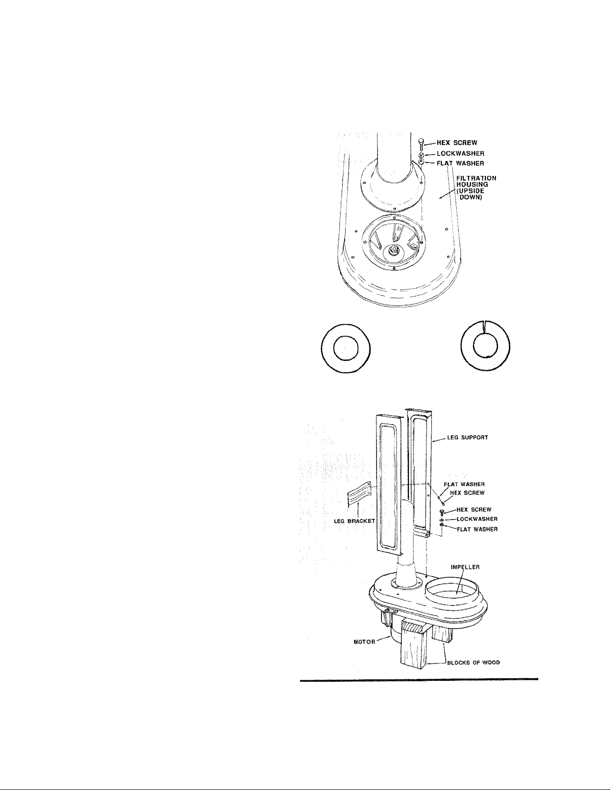
2. Locate the Filtration Housing ar\ö Inlet Guard.
Items are shown actual size
Page 8
assembly
3- Carefully turn the Filtration Housing upside down so
that the Motor endbei! rests against the floor.
■ ( / V u : 7 ' ' V v :
' ^ ; A guard must
y ./ . ' 'Í POINT TO
■■ ■■■, It^REAR OF
. V, . MACHINF.
4. Support the opposite side of Filtration Housing wlh a
block of wood.
A. Place O-Ring in relief of Inlet pipe {See page 18}
5. Position/n/efGuardinlinewiththethreaded holes on
the base of the Filtration Housing.
NOTE: Make surelnlet Guard is pointing to rear of
machine.
6. Place lockwasher and flat washer on hex screw and
insert through the holes of the Inlet Guard into the
threaded holes of the Filtration Housing as shown.
7. Complete the process for the otherthree holes using
same method.
DO NOT SECURE SCREWS AT THIS TIME.
MOUNTING SUPPORT LEGS
1. Locate the following items from the loose parts bag:
Description Qty.
A Flat Washers* {5/16 x 11/16 x 3/32) .....4
B Hex Screws *{M8 x 1.25 - 12)
C Lockwashers* {5/16)
..................
....
..........4
. 4
— INLET GUARD
Items are shown actual size
CAUTION: To avoid injury, keep hands away
from fan blade.
2. Position left Leg Support as shown.
.....
3. Place lockwasher and flat washer on hex screw and
insert through the holes in the Support Leg and
secure to the threaded holes in the Filtration Housing
as shown.
4. Use same method to attach Right Support Leg.
5 . Secure hex screws with the use of adjustable wrench.
MOUNTING LEG BRACKET
1. Locate the following items from the loose parts bag:
Description Qty.
A Flat Washers* (5/16 x 11/16 x 3/32)
B Hex Screws* (M8x 1.25-12)
............
2. Insert Leg Bracket between the Support Legs and
slide against the angled flange of the Leg.
NOTE: Make sure holes in Leg Bracket align with
holes on Leg Support.
3. Place flat washer on hex screw, insert through angled
.....
4
4
flange of Leg Support and attach to threaded hole of
Bracket.
4. Repeat steps 2 and 3 using same process on other
three holes.
Page 9

MOUNTING INLET BRACKET
1. Locate the following items from the loose parts bag:
Description C3ty.
A Flat Washers* (5/16 x 11/16 xi/i6)
B Hex Screws* (M8 x 1.25 -12)
C Flat Washers *{1/4 X 1/2).................................2
D Hex Screws* (M6 x 1 -12)
2. Insert Inlet Bracket between relief flange of Inlet
Guard and against inside edge of angle flange on
Support Leg. Make sure both holes on Bracket align
with similar holes on Leg Support.
3. Place 5/16 flat washer on hex screw, insert through
Leg hole and attach to threaded hole of Bracket.
4. Repeat same process for other hole and secure with
use of adjustable wrench.
5. Attach Fixed Clamp as shown, by placing flat washer
on hex screw, insert hex screw through hole of Fixed
Clamp and attach to threaded hole of inlet Guard
Bracket
6. Repeat step 5 to attach other screw below Inlet
Guard.
...................
..........................
................................
2
2
2
' items are shown actual size
CLAMP AND BRACKET
MOUNT HERE
gli
7. Tighten all screws on Legs. Inlet Guard, and Filtration
Housing securely.
MOUNTING BASE PLATE
1. Locate the following items from the loose parts bag:
Description Qty.
A Flat Washers* (5/16 x 11/16x1/16)
B Hex Screws* (M8 x 1.25 - 12)
2. Attach Base Plate to Leg Supports by flipping base
upside down, aligning holes on both Leg Supports.
3. Place flat washer on hex screw, insert through hole of
Leg and attach to threaded holes in Base Plate as
shown.
4. Repeat same process for other three holes and
secure with adjustable wrench.
5. With the assistance of another person, carefully flip
the Oust Collection System right side up.
......................
...............................
4
4
(o) gni
Items are shown actual size
FIXED CASTERS
SWIVEL CASTERS
Page 10

assembly
MOUNTING FILTER/DUST BAG HOLDER
TO FILTRATION HOUSING
1. Locate the following items from the loose parts bag:
Description
A HexNut* (M6x1)
B Lockwas her* (1/4) ................
C Fiat Washer* {MA x 1/2)
2. Attach hex nut to threaded portion of Filter/Dust Bag
Holder and place lockwasher and flat washer on nut
as shown.
3. Insert Filter/Dust Bag Holder into threaded hole of
Filtration Housing as shwon.
4. Turn Filter/Dust Bag Holder rod clockwise until nut is
secured to Filtration Housing.
5. Secure Filter/Dust Bag Holder in piace with adjust
able wrench.
.................
.........
...............
.............V.1'.'
..................
1
.1
A B
Items are shown actual size
MOUNTING HANDLE TO FILTRATION HOUSING
1. Locate the following items from the loose parts bag:
Description Qty.
A Hex Screws* (M6 x 1 -25)
8 Lockwashers* {1/4" dia.)
C Hex Nuts* (M6x 1)
2. Attach the ends of the Handle to the Relief Flanges on
the side of Filtration Housing as shown.
3 insert hex screw through the Handle and Flange.
4. Attach the lockwasher and the hex nut to the screw
and tighten
5. Repeat process for ali four holes and secure with
adjustable wrench. :
..................
......
............................
4
4
4
to
Page 11

CHIP BAG ASSEMBLY LOWER FiLTRATION HOUSING
1. Insert lower Chip Bag by tilting the Metal Reinforced
Band at an angle and position it through the hole in the
lower Filtration Housing.
2. Tuck one side of the Band under the Sawdust
Chute Extension.
3. Allow the opposite side to rest on the ridge of the
opening.
4. Tug on the Chip Bag to insure proper seating.
UPPER FILTER/DUST BAG ASSEMBLY
FILTBATION HOUSING
SAWOUST CHUTE
extension
1. Disconnect the Adjustable ßandC/ampandinsertthe
end through the loops provided at the opening of the
Fllter/Dust Sag.
2. Invert the Filter/Dust Bag and slip the open end of the
Bag over the 1" Relief on the top opening of the
Filtration Housing.
3. Secure the B^ by adjusting the rectangular barto the
fourth set of hooks.
4. Pull the lever tight until it seats itself.
CAUTION: Make sure the opening of the bag Is
tight against the relief so dust will not escape.
FILTER/
DUST BAG
HOLDER
HANDLE
RELIEF
11
Page 12
operation
This Dust Collection System is designed to be con
nected directly to the woodworking machines. Please,
use only the parts provided for maximum efficiency.
4" Diameter x 60" Hose. PVC Vulcanized rubber
with wire reinforcement and 2 - 4" clamps.
4*72-1/2" Diameter Adapter. This connector allows
direct hookup to many machines including
Bandsaws, Belt and Disk Sanders, and Radial
Saw Sawdust Collector.
WARNING: To avoid fire or explosion caused
by the ignit ing of vapors or dust due to the arcing of
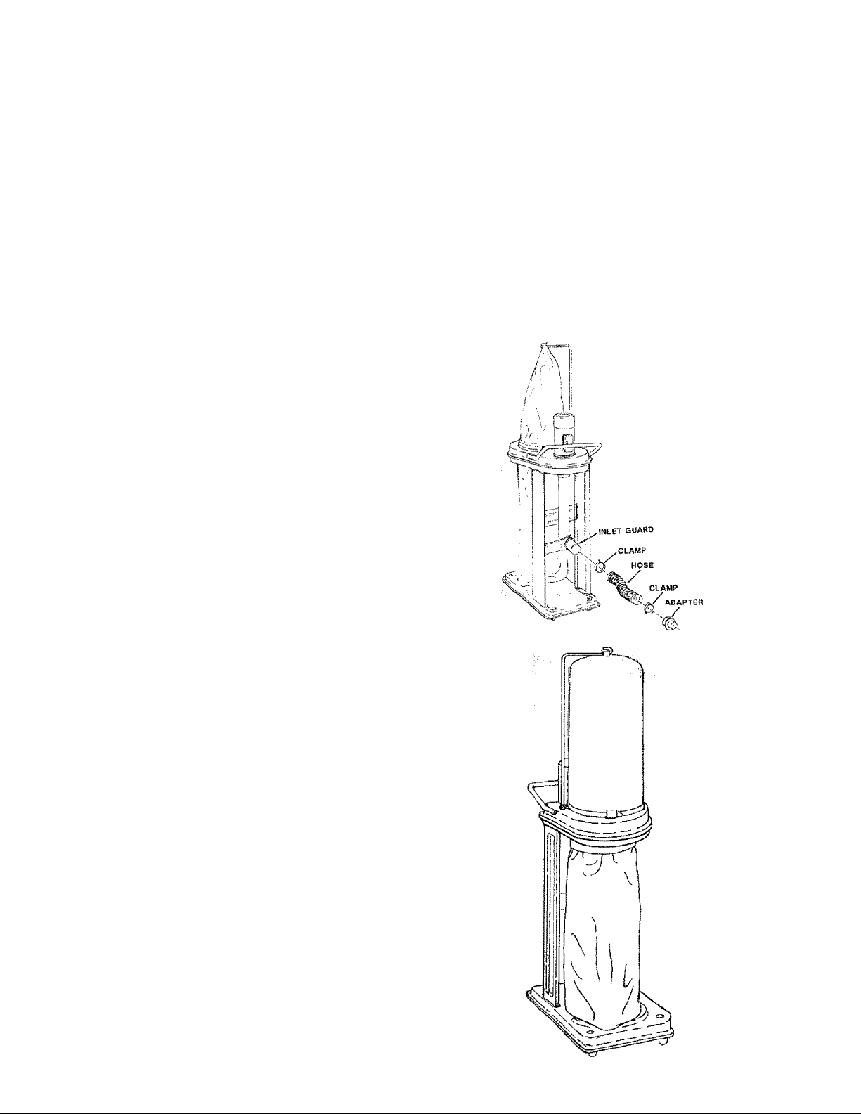
ATTACHING ACCESSORIES TO INLET
GUARD ■ '
4" Diameter Hose/Clamp Assembly and Adapter
1 Open Clamp and insert Hose, by slipping Clamp
;,:iC\6vet Hose. Attach to Inlet Guard and tighten
v CfClampy^ a straight blade screwdriver. Use this
same process to connect Adapter. Tighteh both
Clamps securely to increase air velocity and
The Adapter will permit easy dis-
v; :■ 7 connect. \ ^ i
electricai parts, do not operate this Dust Collection
System In areas with flammable vapors such as
lighter fluid, cleaners, oil-base paints, gasoline,
alcohol or explosive dust such as coal, magnesium,
grain or gun powder in the air. Do not vacuum
explosive dust, flammable or combustible liquids or
hot ashes. To avoid health hazards from vapors or
dusts, do not use near toxic materials. To avoid
electrical shock, do not expose to rain. Store in
doors. Unplug power cord before changing, clean
ing, or emptying the filter/dust bag or chip bag.
CAUTION: To avoid fire, use only the hose and
adaptor designed for this unit. The adapter is de
signed to fit only to the hose. Do not attach it directly
to any other inlet opening.
CONNECTING DUST COLLECTION
SYSTEM TO POWER SOURCE
k CAUTION: If connected to a circuit protected
by fusesi use time delay fuses with this appilance.
1. Prior to connecting your Dust Collection System to
any power source, be sure your bags are installed
properly. Thiswillremoveanypossibilityof dustflying
in your face.
2. The motor on your Dust Collection System is wired for
120 volts, single phase power system. Make sure the
motor rating agrees with the electrical system it is to
be connected to.
3. Too many machines on one circuitwill blow fuses. Be
careful not to overload circuit. •
12
Page 13
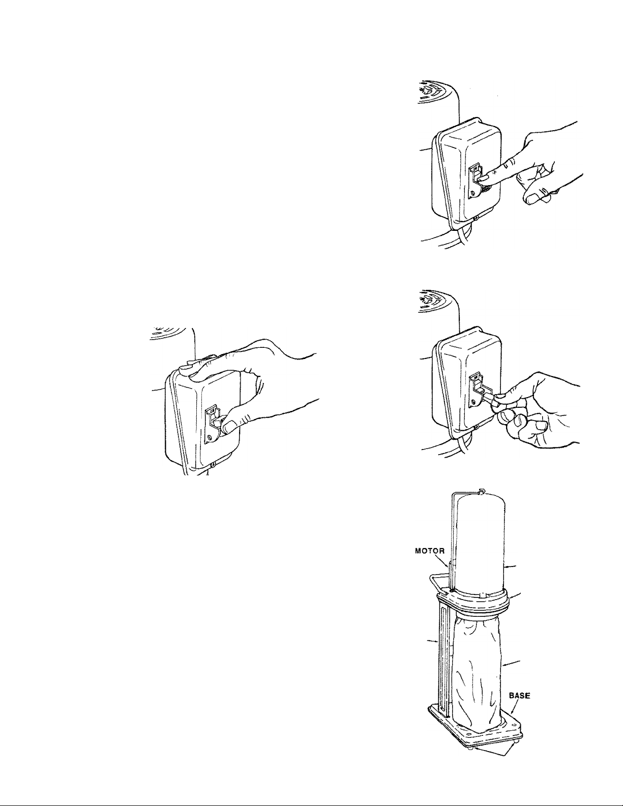
ON/OFF SWITCH
On the rear of the Motor Housing above the Handle, is
the Switch Box. The ON/OFF Switch has the ability to
be turned “ON” v^hen the Red Key is properly
installed. Switch to the “ON" position by moving the
switch upward- Turn the switch “OFF” by moving
downward. Remove the Key from the switch whenev
er the saw is turned “OFF” and keep it out of the reach
of children.
i WARNING: THE DUST COLLECTION SYSTEM
CAN START ACCIDENTALLY OR BE USED BY CHIL
DREN OR OTHERS WHEN THE KEY IS LEFT IN THE
SWITCH. ALWAYS REMOVE KEY WHEN THE DUST
COLLECTION SYSTEM IS 'OFF', AND KEEP IT OUT
OF THE REACH OF CHILDREN.
A WARNING: THE DUST COLLECTION SYSTEM
WILL START IMMEDIATELY WHEN THE POWER
COMES BACK ON AFTER A BLACKOUT IF THE KEY
IS LEFT'ON' IN THE SWITCH. ALWAYS TURN THE
SWITCH 'OFF' AND REMOVE THE KEY.
Turning Switch "ON"
MOVING THE DÜST COLLECTION SYSTEM
This Dust Collection System is able to move easily from
one woodworking machine to another.
CAUTION: To avoid injury from falling unit or
fire from electrical cords, do not cross over large
debris or electric cords when moving unit.
Turning Switch "OFF"
Removing Switch Key
LEG SUPPORT
RLTER/
DUSTBAG
FILTRATION
HOUSING
13
CHIP BAG
CASTERS
Page 14

operation
POWER SUPPLY
WARNING: YOUR DUST COLLECTION SYS-
TION. CONNECT TO A 120V, 15-AfWP, BRANCH
CIRCUIT AND USE A 15-AMP, TIME DELAY FUSE OR
CIRCUIT BREAKER. FAILURE TO CONNECT IN
THIS WAY CAN RESULT IN INJURY FROiW SHOCK
OR FIRE.
Your Dust. Coilection System must be properly
grounded. Not ali.outiets are properly grounded. If you
.are not sure that your outlet is properly grounded,
have it checked by a qualified electrician. , '
A WARNING: IF NOT PROPERLY GROUNDED
THIS DUST COLLECTION SYSTEM CAN CAUSE
ELECTRICAL SHOCK, P ARTICULARLY WHEN USED
IN DAMP LOCATIONS.
WARNING: TO AVOID SHOCK OR FIRE, IF
POWER CORD IS WORN; CUTt OR DAfViAGED IN
ANY WAY. HAVE IT REPLACED IMMEDIATELY.
This appliance is for use on a nominal 120-volt circuit,
and has a grounded plug that looks like the plug iltustratted below. Atemporary adapter may be used to connect
this plug to a 2-pole receptacle, as shown below, if a
properly grounded outlet is not available. The temporary
adapter should be used only until a properly grounded
outlet can be installed by a qualified electrican. The
green colored rigid ear, lug, or the like, extending from
the adapter must be connected to a permanent ground
such as a properly grounded outlet box cover. When
ever the adapter is used, it must be held in place by a
metal screw.
WARNING " IMPROPER CONNECTION
OF THE EQUIPMENT GROUNDING CONDUCTOR
CAN RESULT IN A RISK OF ELECTRIC SHOCK.
CHECK WITH A QUALIFIED ELECTRICAN OR SERV
ICE PERSON IF YOU ARE IN DOUBT AS TO
WHETHERTHEOUTLETIS PROPERLY GROUNDED.
DO NOT MODIFY THE PLUG PROVIDED WITH THE
APPLICANCE IF IT WILL NOT FIT THE OUTLET,
HAVE A PROPER OUTLET INSTALLED BY A QUALI
FIED ELECTRICIAN.
3-PRONG PLUG
GROUNDING INSTRUCTIONS
This appliance must be gfetinded. if it should malfunctioh of breakdown; grounding provides a path of least
resistance for electric cùfféht to rèduce the risk of
etectric shock. This appliahce is equipped with a cord
having an equipment-grounding conductor and ground
ing piug. The plug must be plugged into an appropriate
outlet that is properly iristailed and grounded In accor
dance with all local codes and ordinances.
-A WARNING: TO MAINTAIN PROPER DUST
COLLECTION SYSTEM GROUNDING, WHENEVER
THE OUTLET YOU ARE PLANNING TO USE FOR
THIS POWER TOOL IS OF THE TWO PRONG TYPE,
DO NOT REMOVE OR ALTER THE GROUNDING
PRONG IN ANY MANNER.
EXtENSiON CORDS
The use of any extension cord will cause some loss of
power. Use the fotidwing table to determine the mini
mum wire size (A.W.G.) extension cord. Use only 3-wire
extension cords which have 3-prong grounding type
plugs and 3-pole receptacles which accept the tool's
plug-
For circuits that are farther away from electrical circuit
GROUNDING PRONG
PROPERLY
GROUNDED
OUTLET
GROUNDING LUG
i¥1
3-PRONG PLUG
■ t
¥
ADAPTER
1; \ Ii ti
MAKE SURE THIS f
- CONNECTED TO A
KNOWN GROUND
~~~ 2-PRONG
RECEPTACLE
A WARNING: THE ADAPTER ILLUSTRATED IS
FOR USE ONLY IF YOU ALREADY HAVE A PROP
ERLY GROUNDED 2-PRONG RECEPTACLE.
box, the wire size must be increased proportionately
in order to deliver ample voltage to the sawdust collec-
tion system motor.
Length of
gg,oriud.Q.i:
0 - 25 feet
26 - 50 feet
51 -100 feet
Wire Sizes Required
(American Wire Gage
12py lines
No. 16
No. 14
No. 12
14
Page 15

maintenance
A WARNING: FOR YOUR OWN SAFETY, TURN
SWITCH "OFF'’ AND REMOVE PLUG FROM POWER
SOURCE OUTLET BEFORE MAINTAINING YOUR
DUST COLLECTION SYSTEM.
A WARNING; TO AVOID INJURY FROM ELEC
TRIC SHOCK OR SUDDENLY STARTING UNIT, AL
WAYS REMOVE SWITCH KEY AND KEEP UN
PLUGGED WHILE UNIT IS DISASSEMBLED IN ANY
WAY. ALWAYS REASSEMBLE WITH RECOM
MENDED PARTS BEFORE PLUGGING UNIT IN.
CHIP COLLECTING BAG REMOVAL
1. Push Band up and slide opposite edge to the middle
opening.
2. Lower Band carefully through opening as shown.
Deposit chips in appropriate metal container.
A CAUTION: Wear Safety goggles ANSI Z87.1
to protect your eyes prior to commencing opera
tion.
3. Reconnect the Chip Collecting Bag by sliding the
Band through the hpie and slide the opposite side
under Dust Chute Extension. Seat as shown.
FILTER/DUST BAG REMOVAL
A CAUTION: If using this Dust Collection System
to help keep airborne wood dust In heavy usage
within acceptable limits, you must regularly monitor
air borne dust and maintain Dust Collection System
to avoid exceeding dust limits. Each application Is
unique. Your maintenance schedule must, there
fore, be tailored to your specific use of this Dust
Collection System.
1. Shake the Filter/Dust Bag so the fine dust fails into
lower Chip Coltecting Bag.
2. Disconnect the Adjustable Band Clamp by releasir^
the Spring Lever Clamp.
3. Remove the Filter/Dust Bag and deposit all fine dust
in an appropriate metal container.
4. Reconnect the Bag carefully so the Clamp wraps
around the Bag on ail sides. Adjust the lever to the
fourth hook and fasten securely.
5. Slip loop over hook on Filter/Dust Bag Holder.
15
Page 16

maintenance
MOTOR
Excessive dust in motor could cause excessive heaî in
motor.
Every effort should be made to prevent foreign material
from entering the motor. When operated under condi
tions likely to permit accumulations of dust, dirt, or waste
within the motor, a visual inspection should be made at
freguent intervals. Accumulations of dry dust can usu
ally be blown out successfully.
NOTE: Motors used Oft wood-working tools are particu
larly susceptible toithe accumulation of sawdust and
wood chips and should be blown out or "vacuumed"
frequently to prevent interference with normal rnotor
ventilation.
To remove dust, blow off motor with a low pressure air
^hose.: -
MOTOR
___
CAUT50N; To avoid eye Injury or adverse
reaction to dust, high air pressure should not be
used especially In poorly ventilated areas.
The operator performing this cleaning function should
wear safety goggles and filter mask.
Do not use unit if power cord becomes worn or frayed.
If any servicing {other than the above cleaning) be
comes necessary, it should be performed by an author
ized Sears Service Center.
NOTE: The speed of this motor cannot be regulated or
changed.
' i PROBLEM/)'),
Motor vvilf not run.
Excessive sawdust
in air.
Excessive impeller
noise.
PROBABLE CAUSE
1. Defective cord, plug,
switch and/or motor.
2. Blown fuse.
1. Loose connectors
2. Filter/dust bag and/or
chip collection bag
releasing sawdust.
1. Picked up large wood
chips or debris.
2. Loose impeller.
3. Rubbing impeller.
REMEDY SUGGESTED
1. Consult Sears Service. Any attempt to repair this motor
may create a hazard unless repair is done by a qualified
service technician. Repair service is available at your
nearest Sears store.
2. Check for blown fuses and replace with fuse of proper
capacity.
1 Tighten connections.
2. a. Sawdust trapped between clamp bag and housing,
b. Lower bag is hung up on sawdust shoot extension.
Reposition chip bag properly. See “Maintenance - Chip
Bag".
1. Do not pick up metal or ferrous materials. Stop the machine
and the material will.fall to the bottom of inlet tube.
2. Unplug unit prior to disassembly. Hazardous moving
parts inside. Attach inlet guard before plugging in. Use
a piece of wood to free impeller.
3. Consult Sears Service to repair loose or rubbing impeller,
A repair to the housing may create a hazard unless it is
done by a qualified service technician. Repair service is
available at your nearest Sears store.
;i6
Page 17

PROBLEM
PBOBABLE CAUSE
REMEDY SUGGESTED
Excessive noise.
Motor fails to devel
op full power.
NOTE: LOW VOL
TAGE: (Power out
put of motor de
creases rapidly with
decrease in voltage
at motor terminals.
For example, a
reduction of 10% in
voltage causes a
reduction of 19% in
maximum power
output of which the
motor is capable
and a reduction of
20% in voltage
causes a reduction
of 36% in maximum
power output.)
Motor starts slowly
or fails to come up
to full speed.
1. Motor
1 - Circuit overloaded with
lights, appliances and
other rmtors.
2. Undersize extension cord
or extension cord too
long.
3. General overloading of
power company facilities.
1. Low voltage.
2. Windings burned out
or open.
3. Starting switch will not
operate. (Switch contacts
working properly.)
Capacitor is bad.
1. Have motorchecked by qualified s^rvfce technician. Repair
service is avaiable at your nearest Sears store.
1. Do not use other appliances or motors on same circuit
when using the Dust Collection System.
2. Increase the wire sizes on extension cords, or reduce
length of extension cords. See "Motor Specifications and
Electrical Requirements" section.
3. Request a power check from the power company.
1. Request voltage check from the power company.
2. Have motor repaired or replaced by a qualified service,
technician.
3. Have capacitor replaced by a qualified service technician.
Motor overheats
Motor stalls
(resulting in blown
fuses or tripped
circuit breakers).
Frequent opening of
fuses or circuit
breakers.
NOTE; Motors used on wood-workir>g tools are particularly susceptible to the accorrajlation of saw
dust and wood chips and shouW be btown out or "vacuumed" frequently to prevent interference with
fKjrmal motor ventilation and proper operation of the centrifugally-operated starting switch.
1. Motor overloaded.
2. Improper cooling. (Air
circulation restricted
through motor due to
sawdust, accumulating
inside of motor.)
f. Voltage too low to permit
motor to reach operating
speed.
2. Fuses or circuit breakers
do not have sufficient
capacity.
1. Motor overloaded.
2. Fuses or circuit breakers
dk> not have sufficient
capacity.
1. Clean out sawdust to provide normal air circulation through
motor. See "Maintenance" section.
1. Request voltage check from the power company.
2. Install proper size fuses or circuit breakers.
1 .Install proper size fuses or circxiit breakers.
17
Page 18

repair parts
PARTS LIST FOR CRAFTSMAN
DUST COLLECTION SYSTEM
MODEL 113.299780
18
Page 19

repair parts
PARTS LIST FOR CRAFTSMAN DUST COLLECTION SYSTEiyi
Always order by Part Number > not by Key Number.
MODEL 113.299780
Item
No.
1
2 819172
3 819187
4 819302
5
6 819191
7
8
9 819171 Housing, Upper
10 STD551125
11
12
13 STD551025
14
15 819168
16 819198-1
17 124944
18 819184
19
20 819190
21 819195
22 819194
23 STD835010
24
25
26
Part
No.
819166
819189
STD833025
819192
STD840610 * Nut, Hex M6 X 1
819183
STD833012
819182
819202
819201
STD835012
Description
» A Holder, Fiiler/Dust Bag
* Motor, 1 H.P.
A Switch
A Key, Switch
^ Cord with Plug
Handle
* Screw, Hex Hd.M6x 1-25
Plug, Plastic
* Lockwasher, 1/4
Seal, Housing
* Washer, 1/4 X 1/2 X 1/16
* Screw, Hex M6 x 1-12
Impeller
Washer, Flat 5/8 x 1 -1/2 x
1/8
Nut, Hex 5/8 - 18
A Guard. Impeller
Housing, Lower
Sleeve, Housing Edge
O-Ring, 135mm
A Guard, Inlet
* Screw, Hex Hd. M8x 1.25
-8
Clamp, Inlet Support
Bracket, Inlet Support
* Screw, Hex Hd. M8 x i ,25
- 12
Item
No.
27 819198
28
29
30
31
32
33
34
35 819200
36
37
38
39 819165
40
41 819173 Seal, Motor
42
43
44
45 46-57509-3
46
47
48 819269
Part
No.
819196
819207
819199
819203
STD541037
STD551037
STD541837
819186
819170
819169
819185 Screw, Pan Hd. M4x 16
819188
819167
819174
819267
819268
508298
SP5373
Description
Washe r. Flat 5/16 X 11 /16
X, 3/32
Leg
Caster, Fixed
Base
Caster, Pivoting
* Nut,. Hex 3/8 -16
* Washer. Flat 3/8 x 3/4 x
3/32
* Nut, Acorn 3/8-16
Bracket, Leg
Screw, Pan Hd. M4 x 16
- 12 Ty "AB"
* Bag.. Lower Chip
ik Clamp, Fiiter/Dust Bag
ik Bag. Upper Filter/Dust
- 10 Ty "B"
Key
Capacitor
Cover, Capacitor
* Screw. Pan Hd. M4 x
0.7-10
m Hose, Flex 4.0 Inch
^ Clamp, Hose
^ Adapter. 2-1/2’'/4.0”
* Bag of Loose Parts
(Not Shown)
Owner’s Manual (Not
Shown)
* standard Hardware Item - May Be Purchased Locaiiy,
A WARNING: These items Are Important To The Safety Of This Tool. Do Not Substitute
Common Parts.
* Any attempt to repair or replace electricai parts on this unit may create a HAZARD unless repair
is done by a qualified service technician. Repair service is available at your nearest Sears Store.
19
Page 20

smm
'X r
owners
manual
SERVICE
MODEL NO.
113.299780
Dust Collection
System
DUST COLLECTION SYSTEM
Service is available by returning this unit to the
nearest Sears Service Center/Department through
out the United States.
Mode! and serial numbers may be found on the Motor
Cover of your Dust Collection System.
HOW TO ORDER
REPAIR PARTS
J V
WHEN ORDERING REPAIR PARTS. ALWAYS
GIVE THE FOLLOWING INFORMATION;
PART NUMBER
MODEL NUMBER
113.299780
All parts listed may be ordered from any Sears
Service Center and most Sears stores. If the parts
you need are not stocked locally, your order will be
electronically transmitted to a Sears Repair Parts
Distribution Center for handling.
PART DESCRIPTION
NAME OF ITEM
Dust Collection
System
Sold by SEARS, ROEBUCK AND CO., Chicago, IL. 60684 U.S.A.
Part No. SP5373 Form No. SP5373-1 Printed in Taiwan 10/92
 Loading...