

Craftsman 11329943 Owner’s Manual
CAUTION:
Read SAFETY
RULES and
INSTRUCTIONS
carefully
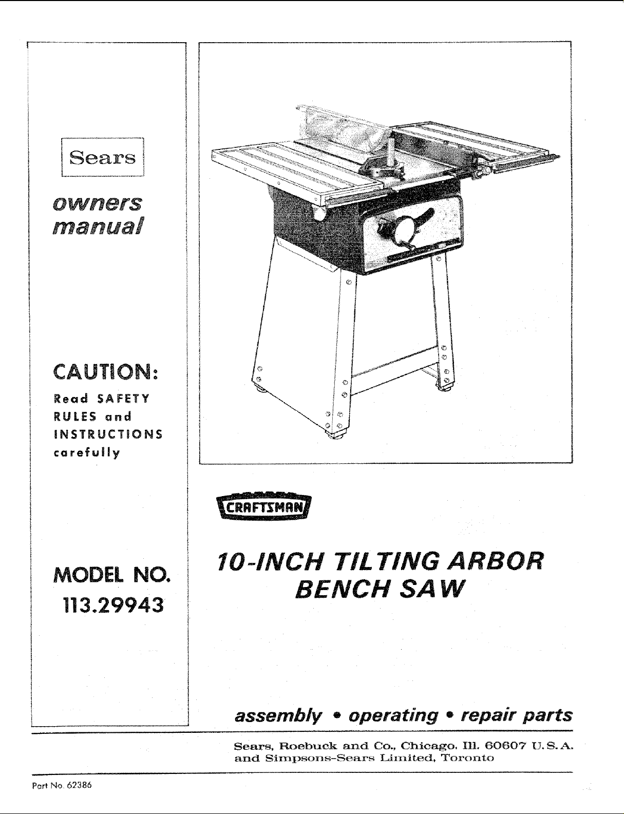
MODEL NO.
113.29943
!
IO-INCH TILTING
BENCH SA
Part No 62386
assembly . operating ,, repair parts
Sears. Roebuck and Co., Chicago, IlL 60607 U,S.Ao
and Sirnpsons-Sears Lin_it_d. Toronto
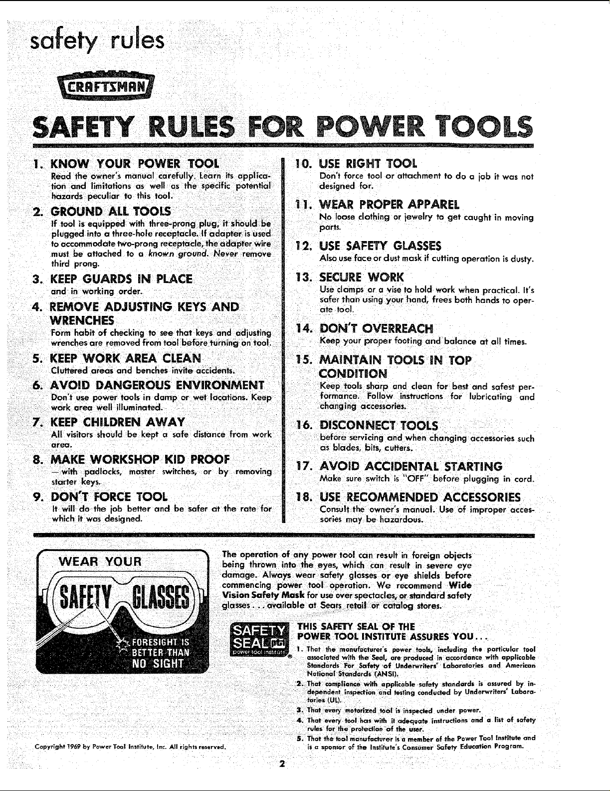
1. KNOW YOUR POWER TOO[
Read the owner's manual carefully. Learn its applica-
tion and limitations as well as the specific potential
hazards peculiar to this tool.
2. GROUND ALL TOOLS
third prong.
3. KEEP GUARDS IN PLACE
and in working order.
4. REMOVE ADJUSTING KEYS AND
WRENCHES
Form habit of checking to see that keys and adjusting
wrenches are removed from tool before turning on tool,
5. KEEP WORK AREA CLEAN
Cluttered areas and benches invite accidents.
6. AVOID DANGEROUS ENVIRONMENT
Don't use power tools in damp or wet locations. Keep
work area well illuminated.
7. KEEP CHILDREN AWAY
All visitors should be kept a safe distance from work
area.
8. MAKE WORKSHOP KID PROOF
--with padlocks, master switches, or by removing
starter keys.
9. DON'T FORCE TOOL
It will do the job better and be safer at the rate for
which it was designed.
10. USE RIGHT TOOL
Don't force tool or attachment to do a job it was not
designed for.
I 1. WEAR PROPER APPAREL
No loose clothing or jewelry to get caught in moving
parts.
12. USE SAFETY GLASSES
Also useface ordust mask if cutting operation is dusty.
13. SECURE WORK
Use clamps or a vise to hold work when practical. It's
safer than usingyour hand, frees both hands to oper-
ate tool.
14. DON'T OVERREACH
Keep your proper footing and balance at all times.
15. MAINTAIN TOOLS iN TOP
CONDITION
Keep tools sharp and clean for best and safest per-
formance. Follow instructions for lubricating and
changing accessories.
16. DgSCONNECT TOOLS
before servicing and when changing accessories such
Qs blades, bits, cutters.
17. AVOID ACCIDENTAL STARTING
Make sure switch is "OFF" before plugging in cord.
18. USE RECOMMENDED ACCESSORIES
Consult the owner's manual. Use of improper acces-
sories ma'/ be hazardous.
Copyright 1969 by Power Too] instifute, inc. AI| righ?s reserved.
The operation of any objects
being thrown into the eyes, which can result in severe eye
damage. Always wear safe_ glasses or eye shields before
commencing power tool operation. We recommend Wide
Vision Safety Mask for use over spectacles, or standard safety
glasses.., available at Sears retail or cata og stores
THIS SAFETY SEAL OF THE
POWER TOOL INSTITUTE ASSURES YOU...
I. That the manufacturer's power tools, including the particular tool
® associated w;_h the Seal, are produced in accordance with applicable
Standards For Safety of Underwriters' laboratories and American
National Standards (AI_SI).
2, That €omplloncu with applicable safety standards is assured by in-
dependent inspection and testing conducted by Underwriters" Labora-
tories (UL).
3, That every motorized t0o! is inspected under power.
4. That every tool has with it adequate instruct|ons and a llst of safety
rules for the protection of the user.
5. That the fool rnanufadurer is a member of the Power Tool Instffute and
is a sponsor of the Instltute's Consumer Safety Education Prog ram.
SASWTY INSTRUCT|ONS TO OP£RATOR
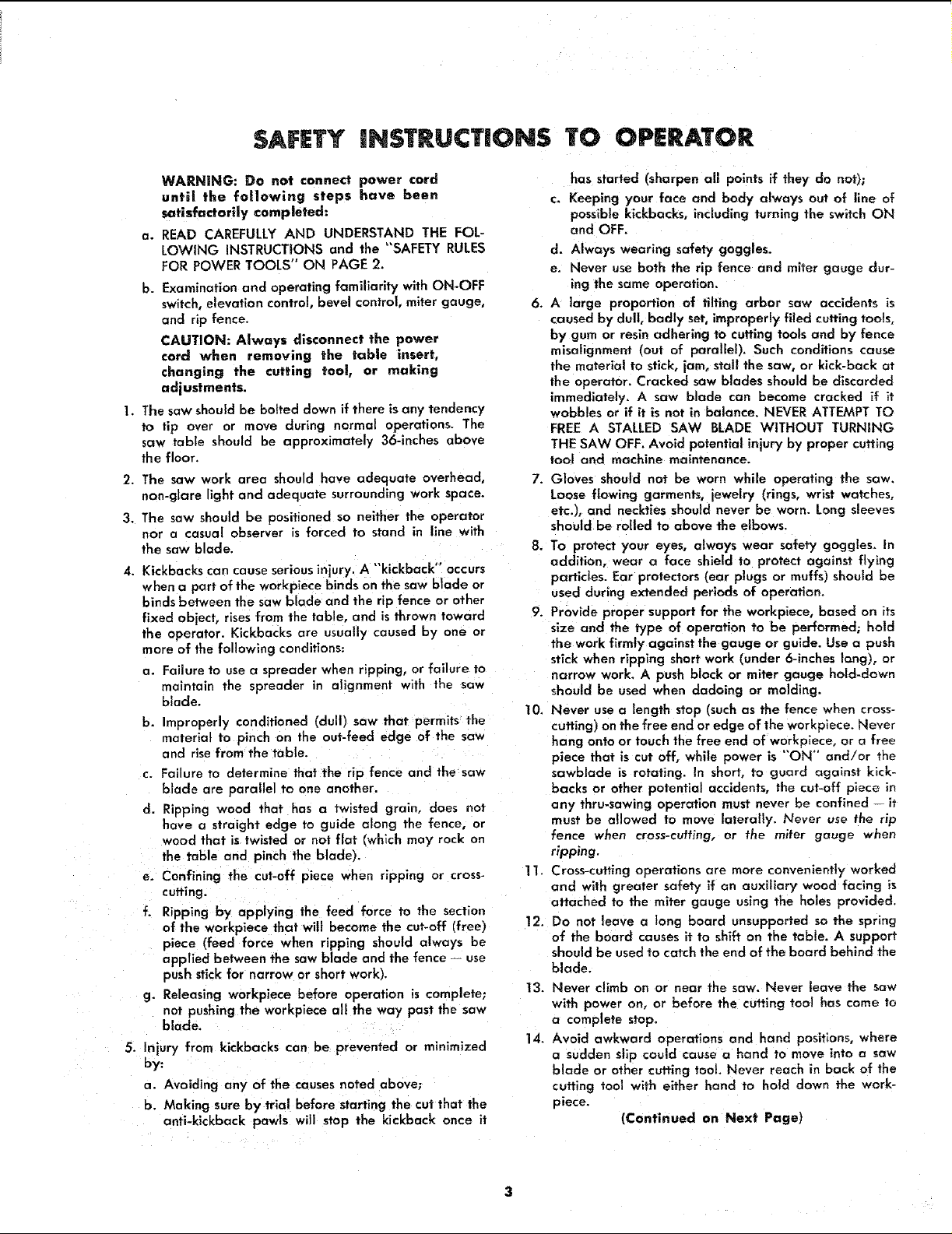
WARNING: Do not connect power cord
until _he following steps have been
satisfactorily completed:
a. READ CAREFULLY AND UNDERSTAND THE FOL-
LOWING INSTRUCTIONS and the "SAFETY RULES
FOR POWER TOOLS" ON PAGE 2.
b. Examination and operating familiarity with ON-OFF
switch, elevation control, bevel control, miter gauge,
and rip fence.
CAUTION: Always disconnect the power
cord when removing the table insert,
changing the cutting too{, or making
adjustments.
1. The saw should be baited down if there is any tendency
to tip over or move during normal operations. The
saw table should be approximately 36-inches above
the floor.
2. The saw work area should have adequate overhead,
non-glare light and adequate surrounding work space.
3. The saw should be positioned so neither the operator
nor o casual observer is forced to stand in llne with
the sow blade.
4. Kickbacks can cause serious injury. A "kickback" occurs
when a part of the workplace binds on the saw blade or
binds between the saw blade and the rip fence or other
fixed object, risesfrom the table, and is thrown toward
the operator. Kickbacks are usually caused by one or
more of the following conditions:
a. Failure to use a spreader when ripping, or failure to
maintain the spreader in alignment with the saw
blade.
b. Improperly conditioned (dull) saw that permits the
material to pinch on the out-feed edge of the saw
and rise from the table.
c. Failure to determine that the rip fence and the saw
blade are parallel to one another.
d. Ri0ping wood that has a twisted grain, does not
hove a straight edge to guide along the fence, or
wood that is twisted or not flat (which may rock on
the table and pinch the blade).
e. Confining the cut-off piece when ripping or cross-
cutting.
f. Ripping by applying the feed force to the section
of the workpiece that will become the cut-off (free)
piece (feed force when ripping should always be
applied between the saw blade and the fence -- use
push stick for narrow or short work).
g. Releasing workpiece before operation is complete;
not pushing the workplace all the way past the saw
blade.
5. Injury from kickbacks can be prevented or minimized
by:
a. Avoiding any of the causes noted above;
b. Making sure by trial before starting the cut that the
anti-kickback pawls will stop the kickback once it
has started (sharpen all points if they do not);
c. Keeping your face and body always out of line of
possible kickbacks, including turning the switch ON
and OFF.
d. Always wearing safety goggles.
e. Never use both the rip fence and miter gauge dur-
ing the same operation,
6. A large proportion of tilting arbor saw accidents is
caused by dull, badly set, improperly filed cutting tools,
by gum or resin adhering to cutting tools and by fence
misalignment (out of parallel). Such conditions cause
the materia{ to stick, jam, stall the saw, or kick-back at
the operator. Cracked saw blades should be discarded
immediately. A saw blade can become cracked if it
wobbles or if it is not in balance. NEVER ATTEMPT TO
FREE A STALLED SAW BLADE WITHOUT TURNING
THE SAW OFF. Avoid potential injury by proper cutting
tool and machine maintenance.
7. Gloves should not be worn while operating the saw.
Loose flowing garments, jewelry (rings, wrist watches,
etc.), and neckties should never be worn. Long sleeves
should be roiled to above the elbows.
8. To protect your eyes, always wear safety goggles. In
addition, wear a face shield to protect against flying
particles. Ear protectors (ear plugs or muffs) should be
used during extended periods of operation.
9. Provide proper support for the workpiece, based on its
size and the type of operation to be performed; hold
the work firmly against the gauge or guide. Use a push
stick when ripping short work (under 6-inches fang), or
marrow work. A push block or mi_r gauge hold-down
should be used when dadoing or molding.
10, Never use a length stop (such as the fence when cross-
cutting) on the free end or edge of the workplace. Never
hang onto or touch the free end of workplace, or a free
piece that is cut off, while power is "ON" and/or the
sawblade is rotating. In short, to guard against kick-
backs or other potential accidents, the cut-off piece in
any thru-sawing operation must never be confined it
must be allowed to move lalera!ly. Never use the rip
fence when cross-cutting, or the miter gauge when
ripping.
1I. Cross-cutting operations are more conveniently worked
and with greater safety if an auxiliary wood facing is
attached to the miter gauge using the holes provided.
12. Do not leave a long board unsupported so the spring
of the board causes it to shift on the table. A support
should be used to catch the end of the board behind the
blade.
13. Never climb on or near the saw. Never leave the saw
with power on, or before the cutting tool has come to
a complete stop.
14. Avoid awkward operations and hand positions, where
a sudden slip could cause a hand to move into a saw
blade or other cutting toot. Never reach in back of the
cutting tool with either hand to hold down the work-
piece.
(Continued an Next Page)
safety instructions to operator
15. Make sure the top of the arbor or cuffing tool rotates
toward you when standing in normal operating position.
Also make sure the cutting tool, arbor collars and arbor
nut are installed properly. Keep the cutting tool as law
as possible for the operation being performed, Keep
all guards in place whenever possible.
]6, Do not use any blade or other cuffing tool marked for
an operating speed in excessof the designspeed of the
saw. Never use a cutting tool larger in diameter than
the diameter for which the saw was designed. For
greatest safety and efficiency when ripping, use the
maximum diameter blade for which the saw is designed,
since under these conditions the spreader is nearest
the blade,
]7. Adjust table inserts flush with, Or slightly below, the
table top.
18. For operations which do not permit the useof a spread-
er, seriousconsideration should be given to the use of
jigs or fixtures to hold the work so the hands of the op-
erator ore removed a safe distance from the point of
operation. (See the booklet "How To Do More _,Nith
Your Bench Saw.")
19. The use of abrasive or cut-off wheels, or wire wheels
can be dangerous and is not recommended. (Abrasive
or cut-off wheelsare used to saw many different ma-
terials including metals, stone, and glass.)
20. Objects can be thrown upward toward the operator by
the back of the blade if proper operating procedures
are not followed. This usually occurswhen a small loose
piece of wood or other object works around to the rear
of the revolving blade. It can usually be avoided by re-
moving all loose pieces from the table immediately
after they are cut off, usinga long stick of wood, and
by keeping the guard and spreader in place at all times.
Use extra caution when the guard assembly is removed
for dadoing or molding, and replace the guard as soon
as that operation is completed.
21. Never perform any operation "freehand." This term
............ the stock into the saw blade or other
cutting tool without using the miter gauge, rip fence,
taper jig, or some other device which prevents rotating
or twisting of the workpiece during the operation.
22. Never turn your saw "ON" before clearing the table
of all objects (tools, scraps of wood, etc.) except the
workpiece and related feed or support devices for the
operation planned.
23. Safety is a combination of operator common senseand
alertness at all times when the saw is being used.
24. Do not cycle the motor switchon and off rapidly, as this
may cause the saw blade to loosen. In the event this
should ever occur, allow the saw blade to come to a
complete step and retighten the arbar nut normally, not
excessively.
\!VARNENG: Do not allow familiarity
(gained from frequent use of your saw) to
became commonplace. Always remember
that a careless fraction of a second is suf-
ficient to inflict severe injury.
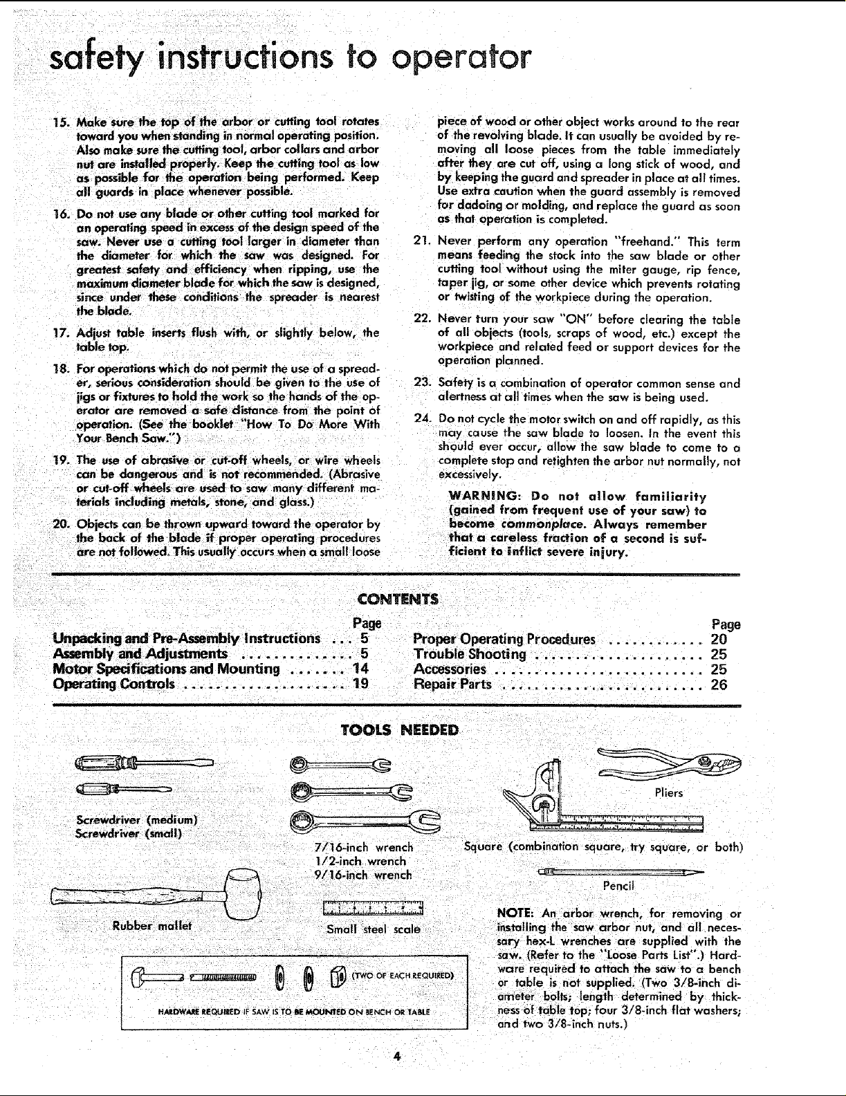
CONTENTS
Page Page
Unpacking and Pre-Assembly Instructions ... 5 Proper Operating Procedures . 20
Motor Specifications and Mounting ....... 14 Accessories ............... 25
Operating Controls .................... 19 Repair Parts ......................... 26
TOOLS NEEDED
Screwdriver (medium)
Screwdriver (small)
Rubber mallet
v _ls_utu_ _ (TWO OF EACH I_EQUIEED)
HARDWARE RIEQUIEEO IF SAW IS TO lie MOUNTED ON BENCH OR TASBE
7/16-inch wrench
1/2-inch wrench
9/16.inch wrench
-_,,._ 4, ,_.r,-1. j-. ,,,
Small steel scale
Square (combination square, try square, or both)
Pencil
ware required to attach the saw to a bench
or table is not supplied. (Two 3/8-inch di-
ameter bolls; length determined by thick-
nessof table top; four 3/8-inch flat washers;
arid two 3/8-inch nuts.l
unpacking and pre-assembJy
UNPACKINGAND PR[°A$SEMBLY
INSTRUCTIONS
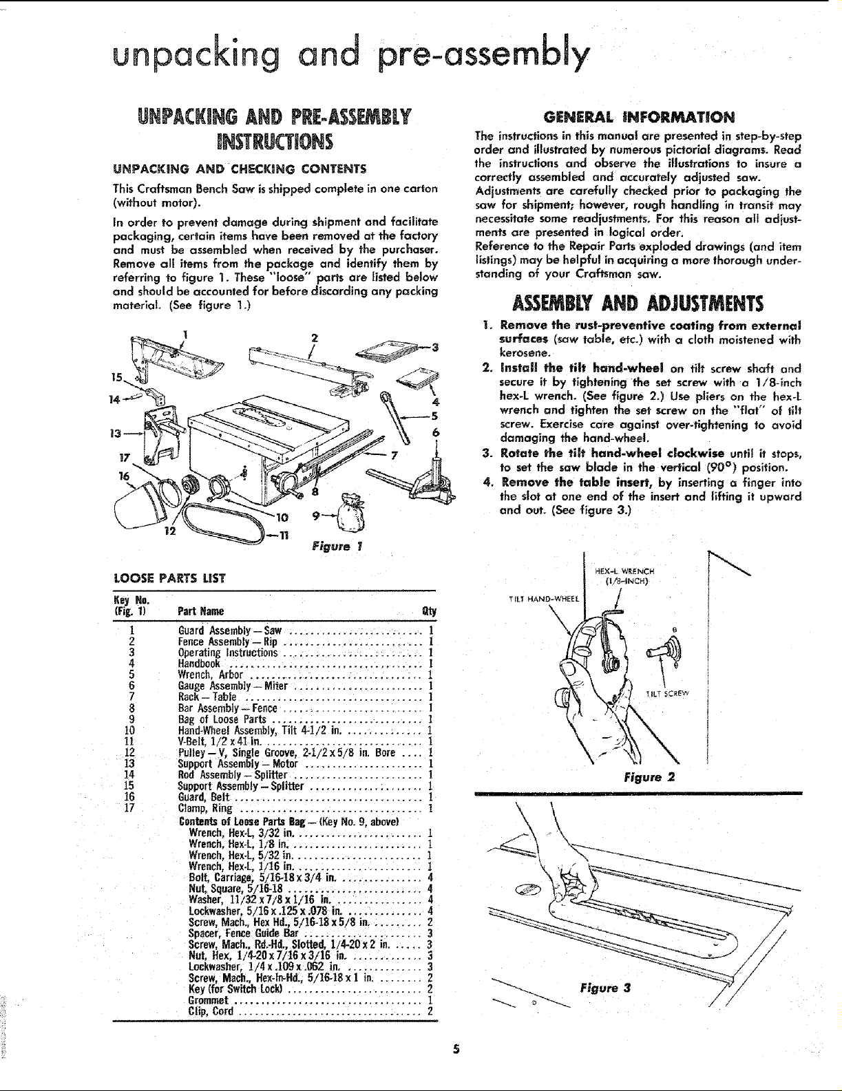
UNPACKING AND CHECKING CONTENTS
This Craftsman Bench Saw is shipped complete in one carton
(without motor).
in order to prevent damage during shipment and facilitate
packaging, certain items have been removed at the factory
and must be assembled when received by the purchaser.
Remove all items from the package and identify them by
referring to figure 1. These "'loose" parts are listed below
and should be accounted for before discording any packing
material (See figure 1.)
GENERJ_L INFOIIMATION
The instructions in this manual are presented in step-by-step
order and illustrated by numerous pictorial diagrams. Read
the instructions and observe the illustrations to insure a
correctly assembled and accurately adjusted saw.
Adjustments are carefully checked prior to packaging the
saw for shipment; however, rough handling in transit may
necessitate some readjustments. For this reason all adiust-
merits are presented in logical order.
Reference to the Repair Parts exp|oded drawings (and item
listings) may be helpful in acquiring a more thorough under-
standing of your Craftsman saw.
Assr BLY AND ADJUSTMENTS
1. Remove the rust-preventive coating from external
surfaces (saw table, etc.) with a cloth moistened with
kerosene.
:2. _nstail the tilt hand-wheel on tilt screw shaft and
secure it by tightening the set screw with a 1/8-inch
hex-L wrench. (See figure 2.) Use pliers on the hex-L
wrench and tighten the set screw on the "flat" of tilt
screw. Exercise care against over-tlghtening to avoid
damaging the hand-wheel.
3. Rotate the tilt hand-whee| clockwise until it stops,
to set the saw blade in the vertical (90 °) position.
4. Remove the table insert, by inserting a finger into
the slot at one end of the insert and lifting it upward
and out. (See figure 3.)
LOOSE PARTS LIST
Key Ha.
(Fig. 1) Part Heine Qty
1 Guard Assembly-Saw ......................... 1
Z Fence Assembly-- Rip .......................... 1
3 Operating Instructions.......................... !
4 Handbook .................................... ]
5 Wrench,Arbor ................................ 1
6 GaugeAssembly - Miter ........................ I
7 Rack- Table ................................. ]
8 Bar Assembly -- Fence ........................ ]
9 Bag of Loose Parts ............................ ]
10 Hand-WheelAssembly, Tilt 4-1/2 in.............. 1
11 V-BelL 1/2 x41 in.............................. ]
12 Pulley--V, Single Groove,2.1/2x5/8 in. Bore .... 1
13 Support Assembly - Motor ...................... !
14 Rod Assembly-Splitter ........................ 1
15 Support Assembly - Splitter ..................... 1
16 Guard,Belt ................................... ]
17 Clamp, Ring .................................. 1
Contentsof LooseParts Bale-- (KeyNo. 9, above)
Wrench,Hex-L,3/32 in.........................
Wrench.Hex-L 1/8 in......................... 1
Wrench,Hex-L, 5/32 in........................ 1
Wrench,flex-L, 1/16 in........................ 1
Bolt, Carriage, 5/16-t8 x 3/4 in................ 4
NuL Square, 5/16-18 ......................... 4
Washer, 11/32 x7/8 x 1/16 in................. 4
Loekwasher, 5/16 x .125x .078 in. .............. 4
Screw,Mach., Rex Hd., 5/16.1S x5/8 in.......... 2
Spacer, FenceGuideBar ...................... 3
Screw, Mach.,Rd.-Rd.,Slotted, 1/4-20 x2 in...... 3
Nut, Flex. t!4-20x7/16x3i]6 in.............. 3
Lockwasher,!/4x.109x.062 in............... 3
Screw, Mach., He×-ln-Hd. 5/16-18 x I in......... 2
Key(for Switch Lock) ......................... 2
Grommet ................................... ]
Clip, Cord .................................. 2
T [LT HAND-WHEEL
\
HEX-L WRENCH
(I/8-1NCH)
Figure 2

adiustrnents
EL_VAT iON fl_D-WHE EL
F_u_ 4
ii
5. Rotate the elevation hand-wheel clockwise until
it stops. This will position the saw blade at maximum
height (deepest cut) position. (See figure 4.)
6. Check tightness of saw arbor nut by wedging a
small block of wood between the saw blade and table
opening, as shown in figure 5, and, using the arbor
wrench supplied with the saw, tighten the nut. (The
nut rotates clockwise to tighten.)
7. Adjust Stop Collars as Follows:
a. Checking and Adjusting the O° Position....
(1) With the saw blade in deepest cut position,
check the tilt position of the saw b|ade by at-
tempting to rotate the tilt hand-wheel clockwise
until it will rotate no farther.
(2) Place a square on the table top and against saw
blade. (See figure 6.) The blade should be at
exactly 90 degrees (perpendicular) to the table-
top surface. (Make sure the square is resting
against the flat surface of blade and is not
being held away by the "tooth-set" of the blade.)
(3) if the blade is not square with table top, rotate
the tilt hand-wheel counterclockwise until the
tilt mechanism movesa shortdistance away from
the stop collar on tilt screw. When the pointer
on tilt scale indicates approximately 10 degrees,
the stop collar can be reached. (See figures 7
and 9.)
(4) Loosen the two set screws in the stop collar,
located on the tilt screw nearest tilt hand-wheel,
with a small screwdriver and rotate the stop
collar counterclockwise at least one turn. (See
_H /_ T,LT I
0_ POSITION
Figure
Figure 6
/
.REAR OF SAW
{ NUT
SET
SCREW
_ T_LT
COLLAR
STOP " ____
Figure 8
SET
SCREW
- SCREW
Two slotted-head set screws (figure 8) are used
in each stop collar so that one of the screws
will always be accessible (with operator reach-
ing inside the saw base from the rear of saw,
figure 9)_ After adjusting the collar, it is only
necessary to tighten one of the set screws to
secure the Collar on the tilt screw.
Rotate the tilt hand-wheel clockwise until the
(5)
saw blade is perpendicular to the saw table--
(6)
Reach inside of saw base (figure 9) and rotate
the stop collar clockwise until it is in firm contact
with the saw cradle. Tighten one of the stop-
collar set screwsenough to keep the collar from
rotating on the tlit screw.
I
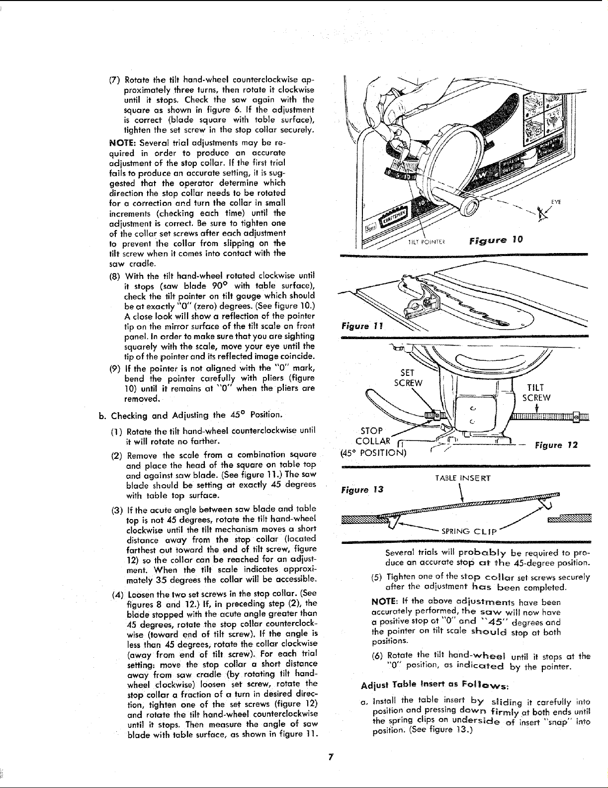
(7) Rotate the tilt hand-wheel counterclockwise ap-
proximately three turns, then rotate it clockwise
until it stops. Check the saw again with the
square as shown in figure 6. If the adjustment
is correct (blade square with table surface),
tighten the set screw in the stop collar securely.
NOTE: Several trial adjustments may be re-
quired in order to produce an accurate
adjustment of the stop collar. If the first trial
fails to produce an accurate setting, it issug-
gested that the operator determine which
direction the stop collar needs to be rotated
for a correction and turn the collar in small
increments (checking each time) until the
adjustment is correct. Be sure to tighten one
of the collar set screws after each adjustment
to prevent the collar from slipping on the
tilt screw when it comes into contact with the
saw cradle.
(8) With the tilt hand-wheel rotated clockwise until
it stops (saw blade 90 ° with table surface),
check the tilt pointer on tilt gauge which should
be at exactly "0" (zero) degrees. (See figure 10.)
A close look will showa reflection of the pointer
tip on the mirror surface of the tilt scale on front
panel. In order to make sure that you are sighting
squarely with the scale, move your eye until the
tip of the pointer and its reflected image coincide.
(9) If the pointer is not aligned with the "0" mark,
bend the pointer carefully with pliers (figure
10) until it remains at "'0" when the pliers are
removed.
b. Checking and Adjusting the 45° Position.
fl ) Rotate the tilt hand-wheel counterclockwise until
it will rotate no farther.
(2) Remove the scale from a combination square
and place the head of the square on table top
and against saw blade. (See figure 1I.) The saw
blade should be setting at exactly 45 degrees
with table top surface.
(3) Efthe acute angle between saw blade and table
top is not 45 degrees, rotate the tilt hand-wheel
clockwise until the tilt mechanism moves a short
distance away from the stop collar (located
farthest out toward the end of tilt screw, figure
12) so the collar can be reached for an adjust-
ment. When the tilt scale indicates approxi-
mately 35 degrees the collar will be accessible.
(4) Loosen the two setscrews in the stop collar. (See
figures 8 and 12.) If, in preceding step (2), the
blade stopped with the acute angle greater than
45 degrees, rotate the stop collar counterclock-
wise (toward end of tilt screw). If the angle is
less than 45 degrees, rotate the collar clockwise
(away from end of tilt screw). For each trial
setting: move the stop collar a short distance
away from saw cradle (by rotating tilt hand-
wheel clockwise) loosen set screw, rotate the
stop collar a fraction of a turn in desired direc-
tion, tighten one of the set screws (figure 12)
and rotate the tilt hand-wheel counterclockwise
until it stops. Then measure the angle of saw
blade with table surface, as shown in figure 11.
\
I!_1 TILT
scREw
c. f
Figure 12
TABLE INSERT
Figure I3 _
Several trials will probc_bly be required to pro-
duce an accurate stop at the 45-degree position.
(5) Tighten one of the stop collar set screws securely
a{ter the adius_.ment has been completed.
NOTE: If the above adjustments have been
accurately performed, the saw will now have
a positive stop at "0" and "'45" degrees and
the pointer on tilt scale should stop at both
positions.
(6) Rotate the tilt hand-vcheel until it stops at the
"0'" position, as indicated by the pointer.
Adjust Table Insert as Follows:
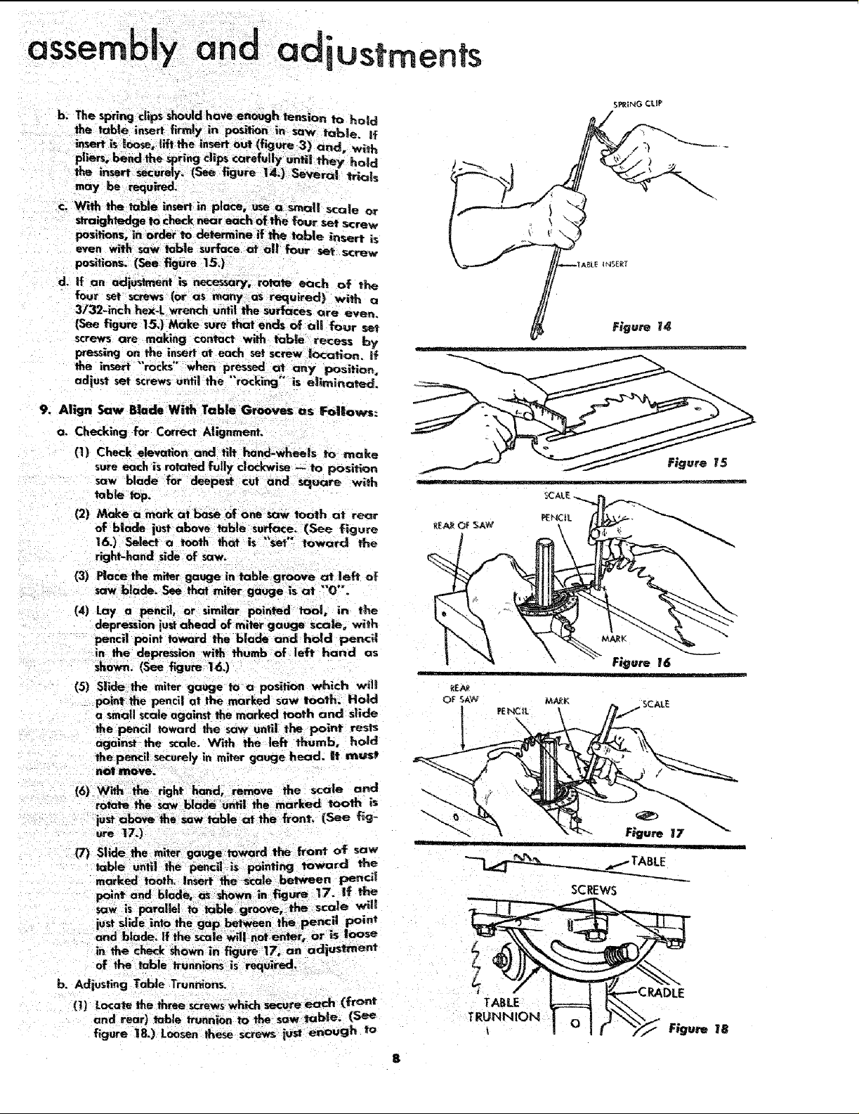
a, Install the table inser,_ by" sliding it carefully into
position and pressing down firmly at both ends until
the spring clips on under'Side of insert "snap" into
position. (See figure 13.)
assembly and adiustments
c. Wffh the table insert in place, use a small scale or
straightedge to check near each of the four set screw
positions, in order to determine if the table ins_ert is
even with saw table surface at all four set screw
positions. (See figure 15.)
d. If an adjush_p_nt is _ry, rotate each of the
S_ING CLIP
,711
(See figure 15,) Make sure that ends of al! four set
screws are making conrad with table recess by
9. Align Saw Blade With Table Grooves os F_|aws:
a. Checking for Correct Alignment.
(I) Check elevation and tlh hand-wheels to make
sure each is rotatad fully cleclcwisa -- to position
saw blade for deepest cut and sc!uare with
(2) Make n mark at _ of one _ tooth at rear
of b|ade just above table su_ce. (Se_ figure
16.) Select a tooth that is set toward the
right-hand side of saw.
(4) Lay a pencil, or similar pointed tool, in the
depression lust ahead of miter gauge scale, with
pencil point toward Hie blade and hold pencil
in the depression with thumb of left hand as
shown. (See figure 163
15) Slide the miter gauge to a position which will
poi_t the pencil at the marked saw tooth. Hold
a small scale against the marked tooth and slide
the pencil toward the saw until the point rests
against the scale. With the left thumb, hold
the pencil securely in miter gauge head. it must
n(Mt mQ_.
(6) With the right hand, remove the scale and
rotate the saw blade until the marked tooth is
just above the saw table at the front, (See f_g-
ure 17.)
(7) Slide the miter gauge toward the front of saw
table untll the pencil is pointing 1owardl the
m_ed tooth. Insert the _le between Pencil
point and blade, as _hown in f',gure 17. If ti_
saw is parallel to table groove, the scale will
just slide into the gap _n the pencil point
and blade. If the sca|e will not enter, or is lOOSe
in the check Shownin figure 17, an adi ustment
of the table trunnions is required.
b.
Adiusting Table Trunnions.
(l) Loca_ lbe three screwswhich secu_'eeach (front
//'- Figu 14
permit each trunnion to "'stip ' when tapped with
a mallet or plastlc-tipped hammer. (If loosened
completely, it would be almost impossib_e to
achieve an accurate Qdiustment. )
(2)
Shift the two trunnions by topping them lightly
until the two measurements described in the pre-
ceding instructions are equal. Tighten the trun-
nion screws and recheck measurements to make
sure tightening screws did nat a_ter the setting.
Several trials may be required to produce an
accurate setting.
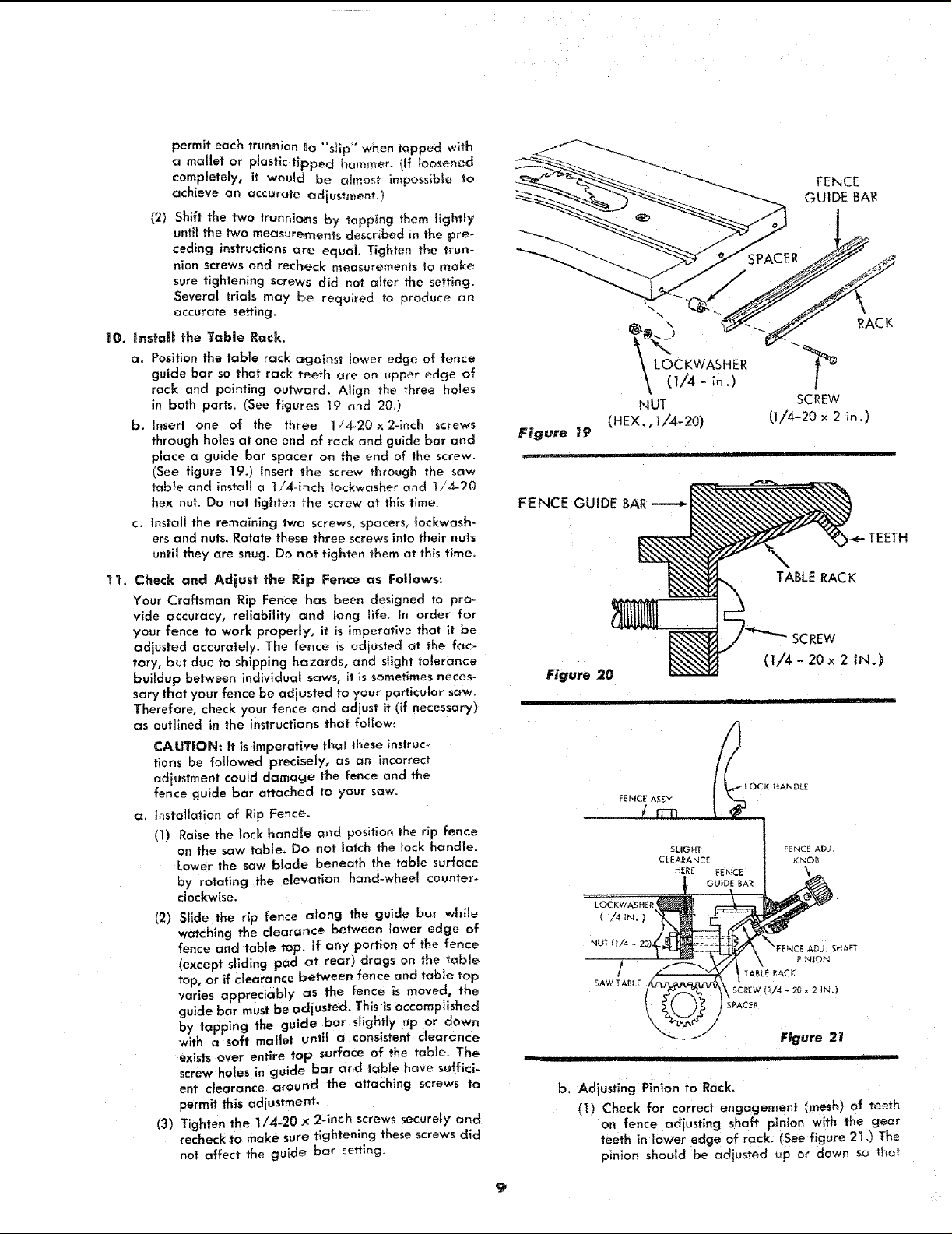
10. Ins_'ali the Table Rack,
a. Position the table rack against lower edge of fence
guide bar so that rack teeth are on upper edge of
rack and pointing outward. Align the three ho_es
in both parts. (See figures 19 and 20.)
b. Insert one of the three 1/4-20 x 2-inch screws
through holes at one end of rack and guide bar and
place a guide bar spacer on the end of the screw.
(See figure 19.) Insert the screw through the saw
table and install a 1!4-inch !ockwasher and 174-20
hex nut. Do not tighten the screw at this time.
c. Instalt the remaining two screws, spacers, Iockwash-
ers and nuts. Rotate these three screws into their nuts
until they are snug. Do not tighten them at this time,
11. Check and Adiust the Rip Fence as Follows:
Your Craftsman Rip Fence has been designed to pro-
vide accuracy, reliability and long llfe. In order for
your fence to work properly, it is imperative that it be
adjusted accurately. The fence is adjusted at the fac-
tory, but due to shipping hazards, and s_ight tolerance
buildup between individual saws, it is sometimes neces-
sary that your fence be adjusted to your particular saw.
Therefore, check your fence and adjust it (if necessary)
as outlined in the instructions that follow:
CAUTION: It is imperative that these instruc_
;'ions be followed precisely, as an incorrect
adiustment could damage the fence and the
fence guide bar attached to your saw.
a. Installation of Rip Fence.
(1) Raise the lock handle and position the rip fence
on the saw table, Do not latch the lock handle.
Lower the saw blade beneath the table surface
by rotating the elevation hand-wheel counter°
clockwise.
12) Slide the rip fence atong the guide bar while
watching the clearance between lower edge of
fence and table top. if any portion of the fence
(except sliding pad at rear) drags on the table
top, or if clearance between fence and table top
vades appreciably as the fence is moved, the
guide bar must be adius ted. This is accomplished
by tapping the guide bar slightly up or down
with a soft mallet until a consistent clearance
exists over entire top surface of the table. The
screw holes in guide bar and table have suffici-
ent clearance around the attaching screws to
permit this adjustment-
(3) Tighten the 1/4-20 × 2qnch screws securely and
recheck to make sure tightening these screws did
not affect the guide bar setting.
@ \
_ LC)CKWASHER
\ fl!4
(HEX., I/4-20)
FENCE GUIDE
Figure 20
LOCKWASHER
( I/4 IN. _
b. Adjusting Pinion to Rack.
(1) Check for correct engagement (mesh) of teeth
on fence adjusting shaft pinion with the gear
teeth in lower edge of rack. (See figure 21.) The
pinion should be adiusted up or down so that
NUT
FENCE
GUIDE BA!R
RACK
SCREW
(I/4-20 ×2 _o.)
TEETH
TABLE RAC K
;REW
(1/4- 20 x 2 iN.)
i i
assembly and adjustments
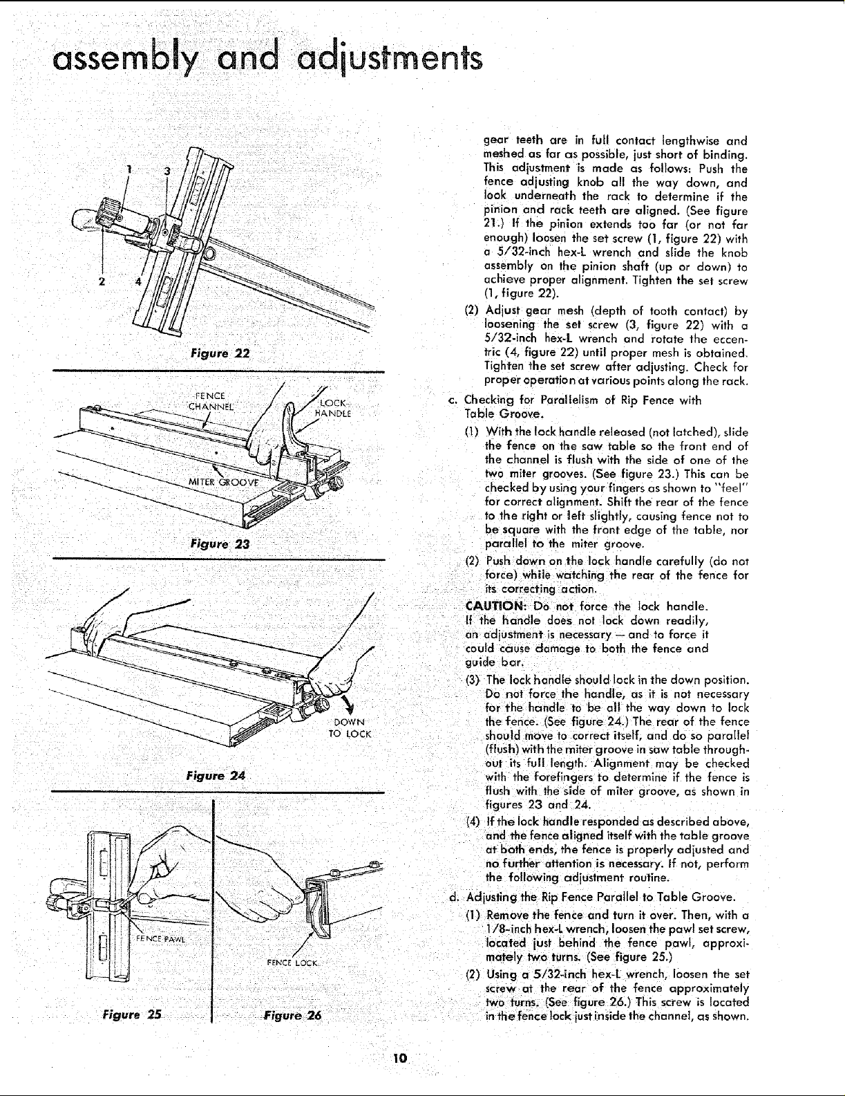
(2) Adjust gear mesh (depth of tooth contact) by
Figure 22
c. Checking for Parallelism of Rip Fence with
Table Groove.
(1) With the lock handle released {not latched), slide
Figure 23
(2) Push down on the lock handle carefully (do not
gear teeth are in full contact lengthwise and
meshed as far as possible, just short of binding.
This adjustment is made as follows: Push the
fence adjusting knob all the way down, and
look underneath the rock to determine if the
pinion and rack teeth are aligned. (See figure
21.) If the pinion extends too far (or not far
enough) loosen the set screw (1, figure 221 with
a 5/32-1rich hex-L wrench and slide the knob
assembly on the pinion shaft (up or down) to
achieve proper alignment. Tighten the set screw
(1, figure 92).
loosening the set screw (3, figure 22) with a
5/32-inch hex-L wrench and rotate the eccen-
tric (4, figure 22) untll proper mesh is obtained.
Tighten the set screw after adjusting. Check for
proper operation at various points along the rack.
the fence on the saw table so the front end of
the channel is flush with the side of one of the
two miter grooves. (See figure 23.) This can be
checked by using your fingers as shown to "'feel"
for correct alignment. Shift the rear of the fence
to the right or left slightly, causing fence not to
be square with the front edge of the table, nor
parallel to the miter groove.
force) while watching the rear of the fence for
-, , CAUTION: Do not force the lock handle.
' ._ could cause damage to both the fence and
-! guide bar.
_'_ Do not force the handle, as it is not necessary
Figure 24
If the handle does not lock down readily,
an adjustment is necessary -- and to force it
its correcting adion.
(3) The lock handle should lock in the clown position.
for the handle to be all the way down to lock
the fence. (See figure 24.) The rear of the fence
should move to correct itself, and do so parallel
I'flush) with the miter groove in saw table through-
out its full length. Alignment may be checked
with the forefingers to determine if the fence is
flush with the side of miter groove, as shown in
figures 23 and 24.
(4) tfthe lock handle responded as described above,
and the fence aligned itself with the table groove
at both enas, the fence is properly odiusted and
no further attention is necessary. If not, perform
the following adjustment routine.
d. Adjusting the Rip Fence Parallel to Table Groove.
(1) Remove the fence and turn it over. Then, with a
1/8-inch hex-L wrench, loosen the pawl set screw,
located just behind the fence pawl, approxi-
mately twotums. (See figure 25.)
(2) Using a 5/32-inch hex-L wrench, loosen the set
screw at the rear of the fence approximately
two turns. (See figure 26.) This screw is located
in thefence lock justinside the channel, as shown.
10
 Loading...