

Craftsman 113299131 Owner’s Manual
Sears
owners
manual
MODEL NO.
113.299131
CRRFTSMRII
CAUTION:
Read SAFETY
RULES and
INSTRUCTIONS
carefully
Sears, Roebuck and Co., Chicago, III. 60684 U.S.A. and Simpsons-Sears Limited, Toronto
Part No. 62465 Printed in U.S.A.
12-INCH MO TORIZED
FL OOR SAW
assembly
operating
repair parts

general safety instructions for power tools
1. KNOW YOUR POWER TOOL
Read the owner's manual carefully. Learn its
application and limitations as well as the specific
potential hazards peculiar to this tool.
2. GROUND ALL TOOLS
This tool is equipped with an approved 3-conductor
cord and a 3-prong grounding type plug to fit the
proper grounding type receptacle. The green conductor
in the cord is the grounding wire. Never connect the
green wire to a live terminal.
3. KEEP GUARDS IN PLACE
and in working order.
4. REMOVE ADJUSTING KEYS
AND WRENCHES
Form habit of checking to see that keys and adjusting
wrenches are removed from tool before turning it on.
5. KEEP WORK AREA CLEAN
Cluttered areas and benches invite accidents. Floor
must not be slippery due to wax or sawdust.
6. AVOID DANGEROUS ENVIRONMENT
Don't use power tools in damp or wet locations. Keep
work area well lit. Provide adequate surrounding work
space.
7, KEEP CHILDREN AWAY
All visitors should be kept a safe distance from work
area.
8. MAKE WORKSHOP KID-PROOF
- with padlocks, master switches, or by removing
starter keys.
9. DON'T FORCE TOOL
It will do the job better and safer at the rate for which
it was designed.
10. USE RIGHT TOOL
Don't force tool or attachment to do a job it was not
designed for.
11. WEAR PROPER APPAREL
No loose clothing, gloves, neckties or jewelry to get
caught in moving parts. Rubber-soled footwear is
recommended for best footing.
12. USE SAFETY GOGGLES
Safety gogglesmust comply with ANS Z87.1-1968.
Also useface or dust mask if cutting operation is dusty.
13. SECURE WORK
Use clamps or a vise to hold work when practical. It's
safer than using your hand, frees both handsto operate
tool.
14. DON'T OVERREACH
Keep proper footing and balance at all times.
15. MAINTAIN TOOLS WITH CARE
Keep tools sharp and clean for best and safest
performance. Follow instructions for lubricating and
changing accessories.
16. DISCONNECT TOOLS
before servicing; when changing accessories such as
blades, bits, cutters, etc.
17. AVOID ACCIDENTAL STARTING
Make sure switch is in "OFF" position before plugging
in.
18. USE RECOMMENDED ACCESSORIES
Consult the owner's manual for recommended
accessories. Follow the instructions that accompany
the accessories. The use of improper accessoriesmay
causehazards.
19. NEVER STAND ON TOOL
Serious injury could occur if the tool istipped or if the
cutting tool is accidentally contacted.
Do not store materials above or near the tool such that
it is necessary to stand on the tool to reach them.
CHECK DAMAGED PARTS
20.
A guard or other part that is damaged should be
properly repaired or replaced before further use of the
tool.
Carefully check the repaired or new part to assure that
it will operate properly and perform its intended
function.
If power cord is worn or cut, or damaged in any way,
have it replaced immediately.
The operation of any power tool can result in foreign objects being
thrown into the eyes, which can result in severe eve damage. Always
wear safety goggles complying with ANS Z87.1-1968 before
commencing power tool operation. We recommend Wide Vision
Safety Mask for use over spectacles, or standard safety goggles ...
available at Sears retail or catalog stores.
THIS SAFETY SEAL OF THE
POWER TOOL INSTITUTE ASSURES YOU...
1. That the manufacturer's power tools, including the particular tool
assoc;ated w;th the Seal, are produced in accordance with applicable
,Standards For Safety of Underwriters' Laboratories and American
National Standards (ANSI).
2. That compliance with applicable safety standards is assured by in-
dependent inspection and testing conducted by Underwriters' Labora-
tories (UL).
3. That every motorized tool is inspected under power.
4. That every tool has with it adequate instructions and a llst of safety
rules for the protection of the user.
5. That the tool manufacturer is a member of the Power Tool Institute and
is a sponsor of the Institute's Consumer Safety Education Program.
2 Copyright 1969 by Powe r Tool Institute, Inc. AI_ r_ghts reserved.
SAFETY INSTRUCTIONS TO OPERATOR
WARNING: Do not connect power cord
until the following steps have been
satisfactorily completed:
a. READ CAREFULLY AND UNDERSTAND THE FOL-
LOWING INSTRUCTIONS and the "SAFETY RULES
FOR POWER TOOLS" ON PAGE 2.
b. Examination and operating familiarity with ON-OFF
switch, elevation control, bevel control, miter gauge,
and rip fence.
CAUTION: Always disconnect the power
cord when removing the table insert,
changing the cutting tool, or making
adjustments.
1. The saw should be bolted down if there is any tendency
to tip over or move during normal operations. The
saw table should be approximately 36-inches above
the floor.
2. The saw work area should have adequate overhead,
non-glare light and adequate surrounding work space.
3. The saw should be positioned so neither the operator
nor a casual observer is forced to stand in line with
the saw blade.
4. Kickbacks can cause Serious injury. A "kickback" occurs
when a part of the workplece binds on the saw blade or
binds between the saw blade and the rip fence or other
fixed object, rises from the table, and is thrown toward
the operator. Kickbacks are usually caused by one or
more of the following conditions:
a. Failure to use a spreader when ripping, or failure to
maintain the spreader.in alignment with the saw
blade.
b. Improperly conditioned (dull) saw that permits the
material to pinch on the out-feed edge of the saw
and rise from the table.
c. Failure to determine that the rip fence and the saw
blade are parallel to one another.
d. Ripping wood that has a twisted grain, does not
have a straight edge to guide along the fence, or
wood that is twisted or not flat (which may rock on
the table and pinch the blade).
e. Confining the cut-off piece when ripping or cross-
cutting.
f. Ripping by applying the feed force to the section
of the workplece that will become the cut-off (free)
piece (feed force when ripping should always be
applied between the saw blade and the fence -- use
push stick for narrow or short work).
g. Releasing workplece before operation is complete;
not pushing the workpiece all the way past the saw
blade.
5. Injury from kickbacks can be prevented or minimized
by:
a. Avoiding any of the causes noted above;
b. Making sure by trial before starting the cut that the
anti-kickback pawls will stop the kickback once it
has started (sharpen all points if they do not);
c. Keeping your face and body always out of line of
possible kickbacks, including turning the switch ON
and OFF.
d. Always wearing safety goggles.
e. Never use both the rip fence and miter gauge dur-
ing the same operation.
6. A large proportion of tilting arbor saw accidents is
caused by dull, badly set, improperly filed cutting tools,
by gum or resin adhering to cutting tools and by fence
misallgnment (out of parallel) with the saw blade. Such
conditions cause the material to stick, jam, stall the saw,
or kick-back at the operator. Cracked saw blades should
be discarded immediately. A saw blade can become
cracked if it wobbles or if it is not in balance. NEVER
ATTEMPT TO FREEA STALLED SAW BLADE WITHOUT
TURNING THE SAW OFF. Avoid potential injury by
proper cutting tool and machine maintenance.
7. Gloves should not be worn while operating the saw.
Loose flowing garments, jewelry (rings, wrist watches,
etc.), and neckties should never be worn. Long sleeves
should be rolled to above the elbows.
8. To protect your eyes, always wear safety goggles. In
addition, wear a face shield to protect against flying
particles. Ear protectors (ear plugs or muffs) should be
used during extended periods of operation.
9. Provide proper support for the workpiece, based on its
size and the type of operation to be performed; hold
the work firmly against the gauge or guide. Use a push
stick when ripping short work (under 6-inches long), or
narrow work. A push block or miter gauge hold-down
should be used when dadoing or molding.
10. Never use a length stop (such as the fence when cross-
cutting) on the free end or edge of the workpiece. Never
hang onto or touch the free end of workpiece, or a free
piece that is cut off, while power is "ON" and/or the
sawblade is rotating. In short, to guard against kick-
backs or other potential accidents, the cut-off piece in
any thru-sawing operation must never be confined -- it
must be allowed to move laterally. Never use the rip
fence when cross-cuftlng, or the miter gauge when
ripping.
11. Cross-cutting operations are more conveniently worked
and with greater safety if an auxiliary wood facing is
attached to the miter gauge using the holes provided.
12. Do not leave a long board unsupported so the spring
of the board causes it to shift on the table. A support
should be used to catch the end of the board behind the
blade.
13. Never climb on or near the saw. Serious injury could
occur if the tool is tipped or if the cutting tool is acci-
dently contacted. Never leave the saw with power on,
or before the cutting tool has come to a complete stop.
14. Avoid awkward operations and hand positions, where
a sudden slip could cause a hand to move into a saw
blade or other cutting tool. Never reach in back of the
cutting tool with either hand to hold down the work-
piece.
15. Make sure the top of the arbor or cutting tool rotates
toward you when standing in normal operating position.
Also make sure the cutting tool, arbor collars and arbor
nut are installed properly. Keep the cutting tool as low
as possible for the operation being performed. Keep
all guards in place whenever possible.
16. Do not use any blade or other cutting tool marked for
an operating speed in excess of the design speed of the
saw. Never use a cutting tool larger in diameter than
the diameter for which the saw was designed. For
greatest safety and efficiency when ripping, use the
maximum diameter blade for which thesaw is designed,
since under these conditions the spreader is nearest
the blade.
(Continued on Next Page)
SAFETY INSTRUCTIONS TO OPERATOR
17.
Adjust table inserts flush with, or slightly below, the
table top.
18.
For operations which do not permit the use of a spread-
er, serious consideration should be given to the use of
jigs or fixtures to hold the work so the hands of the op-
erator are removed a safe distance from the point of
operation.
19.
The use of abrasive or cut-off wheels, or wire wheels
can be dangerous and is not recommended. (Abrasive
or cut-off wheels are ,used to saw many different ma-
terials including metals, stone, and glass.)
20.
Objects can be thrown upward toward the operator by
the back of the blade if proper operating procedures
are not followed. ?his usually occurs when a small loose
piece of wood or other object works around to the rear
of the revolving blade. It can usually be avoided by re-
moving all loose pieces from the table immediately
after they are cut off, using a long stick of wood, and
by keeping the guard and spreader in place at all times.
Use extra caution when the guard assembly is removed
for dadoing or molding, and replace the guard as soon
as that operation is completed.
21.
Never perform any operation "freehand." This term
means feeding the stock into the saw blade or other
cutting tool without using the miter gauge, rip fence,
taper jig, or some other device which prevents rotating
or twisting of the workpiece during the operation.
22.
Never turn your saw "ON" before clearing the table
of all objects (tools, scraps of wood, etc.) except the
workpiece and related feed or support devices for the
operation planned.
23.
Safety is a combination of operator common sense and
alertness at all times when the saw is being used.
24.
Do not cycle the motor switch on and off rapidly, as this
may cause the saw blade to loosen. In the event this
should ever occur, allow the saw blade to come to a
complete stop and retighten the arbor nut normally, not
excessively.
WARNING: Do not allow familiarity
(gained from frequent use of your saw) to
become commonplace. Always remember
that a careless fraction of a second is suf-
ficient to inflict severe injury.
CONTENTS
Page
Unpacking and Pre-Assembly Instructions .... 4
Power Supply and Motor Data ........... 5
Assembly and Adjustments ................ 6
Operating Controls ....................... 16
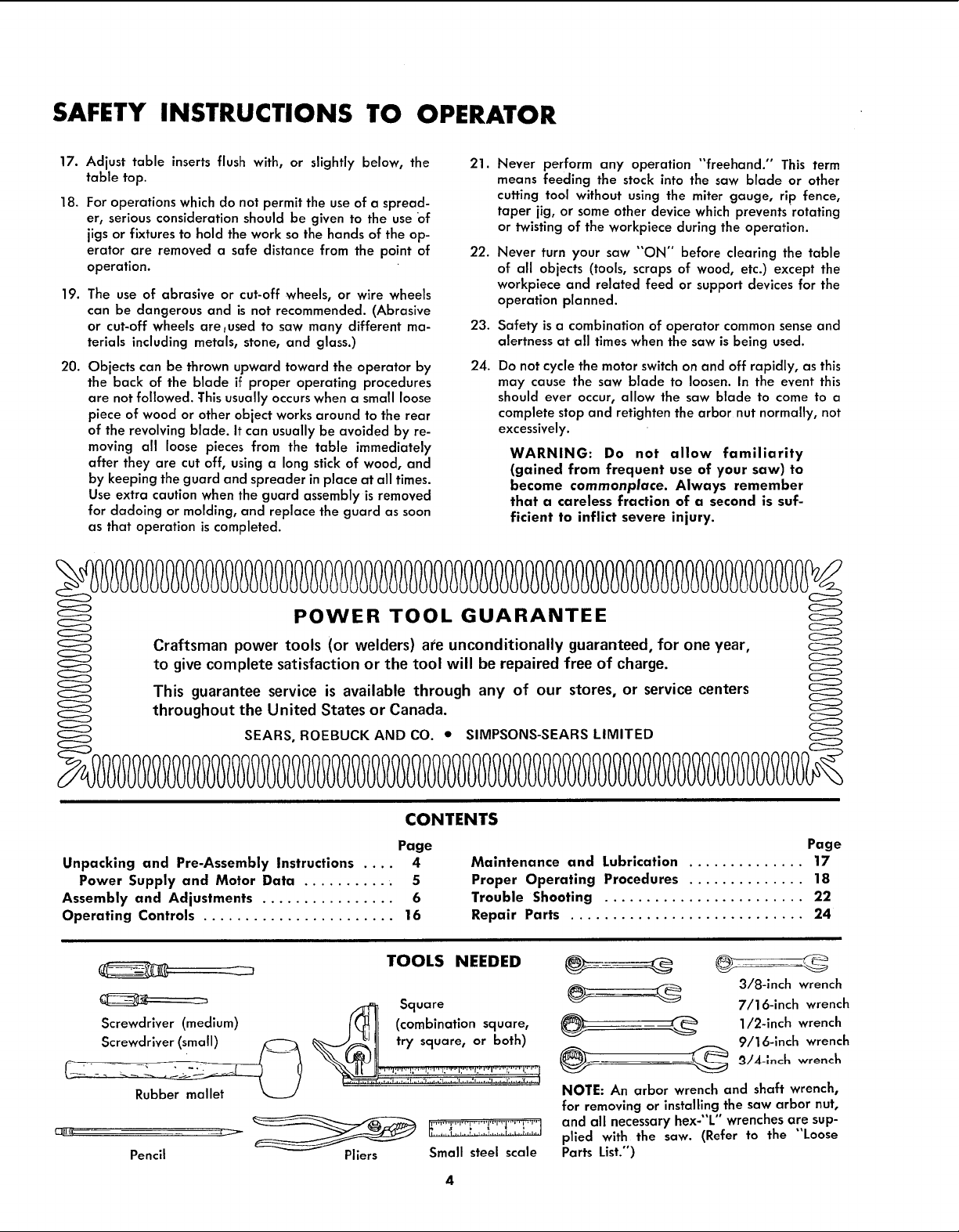
TOOLS NEEDED
_ Square
Screwdriver (medium)
Screwdriver (small) I_ ]J (combination square,
Pencil
Pliers Small steel scale
Page
Maintenance and Lubrication .............. 17
Proper Operating Procedures .............. 18
Trouble Shooting ........................ 22
Repair Parts ............................ 24
3/8-1nch wrench
7/16-inch wrench
_ _ 1/2-inch wrench
NOTE: An arbor wrench and shaft wrench,
for removing or installing the saw arbor nut,
and all necessary hex-"L" wrenches are sup-
plied with the saw. (Refer to the "'Loose
Parts List.")
9/16-1nch wrench
unpacking and pre-assembly
4 S
6
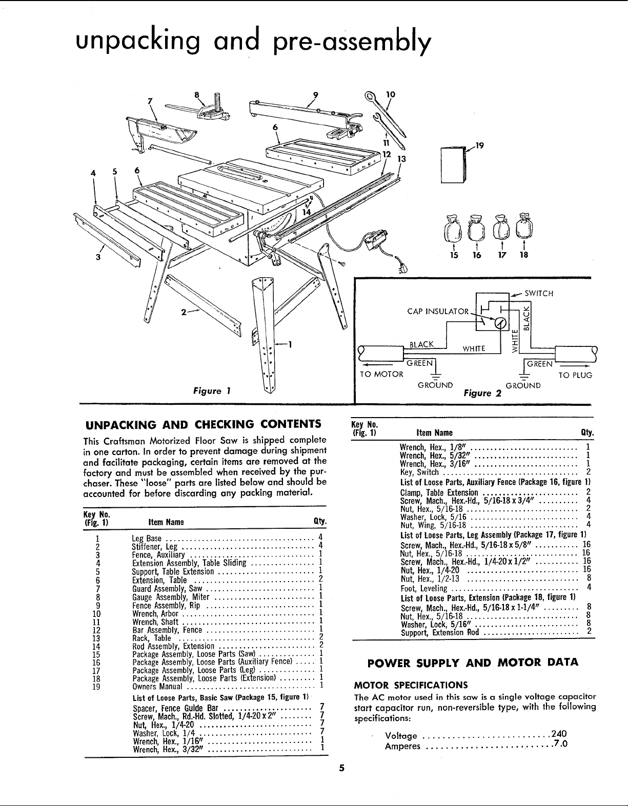
Figure 1
UNPACKING AND CHECKING CONTENTS
This Craftsman Motorized Floor Saw is shipped complete
in one carton. In order to prevent damage during shipment
and facilitate packaging, certain items are removed at the
factory and must be assembled when receiyed by the pur-
chaser. These "loose" parts are listed below and should be
accounted for before discarding any packing material.
KeyNo.
IFig.1) ItemName Qty.
1
2
3
4
5
6
7
8
9
10
11
12
13
14
15
16
17
18
19
Leg Base ..................................... 4
Stiffener, Leg ................................. 4
Fence, Auxiliary ............................... 1
Extension Assembly, Table Sliding ................ 1
Support, Table Extension ........................ 1
Extension, Table .............................. 2
Guard Assembly, Saw ........................... I
Gauge Assembly, Miter ......................... 1
Fence Assembly, Rip ........................... 1
Wrench, Arbor ................................. 1
Wrench, Shaft ................................. 1
Bar Assembly, Fence ........................... 1
Rack, Table .................................. 2
RodAssembly, Extension ........................ 2
Package Assembly,Loose Parts (Saw).............. 1
Package Assembly,Loose Parts (Auxiliary Fence) ..... 1
Package Assembly, Loose Parts (Leg) .............. 1
Package Assembly, Loose Parts (Extension)......... 1
Owners Manual ................................ 1
List of Loose Parts,BasicSaw (Package15, figure 1)
Spacer, Fence Guide Bar ...................... 7
Screw, Mach.,Rd.-Hd. Slotted, 1/4-20 x 2" ........ 7
Nut, Hex., 1/4-20 ............................ 7
Washer, Lock,1/4 ............................ 7
Wrench,Hex., 1/16" .......................... 1
Wrench,Hex., 3/32" .......................... 1
t t t t
15 16 17 18
ii
Key No.
(Fig. 1) Item Name Qty.
Wrench, Hex., 1/8 ........................... 1
Wrench, Hex., 5/32" .......................... 1
Wrench, Hex., 3/16" .......................... 1
Key, Switch .................................. 2
List of LooseParts,AuxiliaryFence(Package16, figure 1)
Clamp, Table Extension........................ 2
Screw, Mach., Hex.-Hd.,5/16-18 x 3/4" .......... 4
Nut, Hex., 5/16-18 ............................ 2
Washer, Lock,5/16 ........................... 4
Nut, Wing, 5/16-18 ........................... 4
List of LooseParts,LegAssembly(Package17, figure 1)
Screw, Mach., Hex.-Hd.,5/16-18 x 5/8" ........... 16
Nut, Hex., 5/16-18 ............................ !6
Screw, Mach., Hex..Hd., 1/4-20xl/2" ........... 15
Nut, Hex., 1/4-20 ............................ 16
Nut, Hex., 1/2-13 ............................ 8
Foot, Leveling................................ 4
List of LooseParts,Extension(Package18, figure 1)
Screw, Mach., Hex.-Hd.,5/16-18 x 1-1/4" ......... 8
Nut, Hex., 5/16-18 ............................ 8
Washer, Lock,5/16" .......................... 8
Support,ExtensionRod ........................ 2
POWER SUPPLY AND MOTOR DATA
MOTOR SPECIFICATIONS
The AC motor used in this saw is a single voltage capacitor
start capacitor run, non-reversible type, with the following
specifications:
Voltage .......................... 240
Amperes .................... ....... 7.0
II
assembly and adjustments
GROUNDINGBLADE_S I!'y/Z-//' f_ _ I 'EG
" ./'_I / NO ADAPTER IS I _ ! OVERLOAD I
Jfl I AVAILABLEFORI _ J PROTECTORI
" II TH'sTYPE LU°I I
Figure 3 J Figure 4 | Figure 5
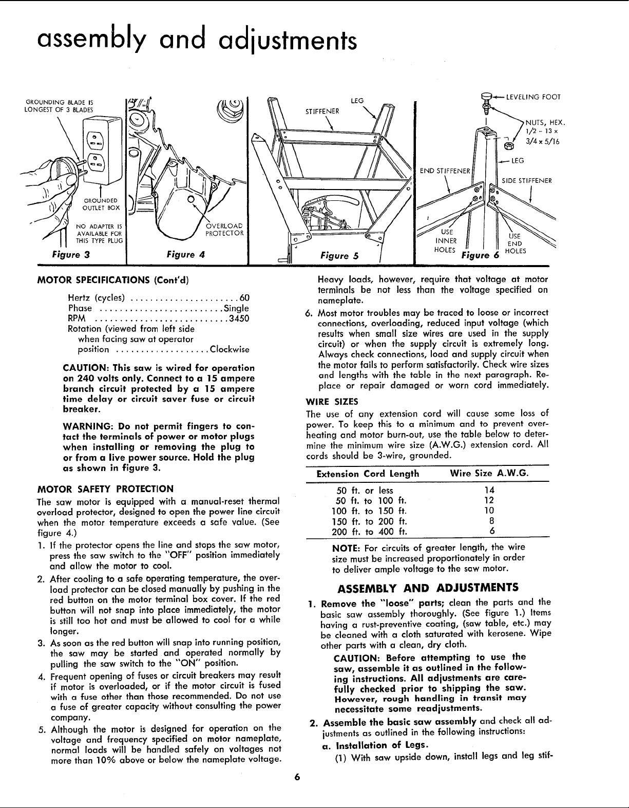
MOTOR SPECIFICATIONS (Cont°d)
Hertz (cycles) ...................... 60
Phase ......................... Single
RPM ........................... 3450
Rotation (viewed from left side
when facing saw at operator
position ................... Clockwise
CAUTION: This saw is wired for operation
on 240 volts only. Connect to a 15 ampere
branch circuit protected by a 15 ampere
time delay or circuit saver fuse or circuit
breaker.
WARNING: Do not permit fingers to con-
tact the terminals of power or motor plugs
when installing or removing the plug to
or from a live power source. Hold the plug
as shown in figure 3.
MOTOR SAFETY PROTECTION
The saw motor is equipped with a manual-reset thermal
overload protector, designed to open the power line circuit
when the motor temperature exceeds a safe value. (See
figure 4.)
1. If the protector opens the line and stopsthe saw motor,
press the saw switch to the "OFF" position immediately
and allow the motor to cool.
2. After cooling to a safe operating temperature, the over-
load protector can be closed manually by pushing in the
red button on the motor terminal box cover. If the red
button will not snap into place immediately, the motor
is still too hot and must be allowed to cool for a while
longer.
3. As soon asthe red button will snap into running position,
the saw may be started and operated normally by
pulling the saw switch to the "'ON" position.
4. Frequent opening of fuses or circuit breakers may result
if motor is overloaded, or if the motor circuit is fused
with a fuse other than those recommended. Do not use
a fuse of greater capacity without consulting the power
company.
5. Although the motor is designed for operation on the
voltage and frequency specified on motor nameplate,
normal loads will be handled safely on voltages not
more than 10% above or below the nameplate voltage.
I
Heavy loads, however, require that voltage at motor
terminals be not less than the voltage specified on
nameplate.
.
Most motor troubles may be traced to loose or incorrect
connections, overloading, reduced input voltage (which
results when small size wires are used in the supply
circuit) or when the supply circuit is extremely long.
Always check connections, load and supply circuit when
the motor fails to perform satisfactorily. Check wire sizes
and lengths with the table in the next paragraph. Re-
place or repair damaged or worn cord immediately.
WIRE SIZES
The use of any extension cord will cause some loss of
power. To keep this to a minimum and to prevent over-
heating and motor burn-out, use the table below to deter-
mine the minimum wire size (A.W.G.) extension cord. All
cords should be 3-wire, grounded.
Extension Cord Length Wire Size A.W.G.
50 ft. or less 14
50 ft. to 100 ft. 12
100 ft. to 150 ft. 10
150 ft. to 200 ft. 8
200 ft. to 400 ft. 6
NOTE: For circuits of greater length, the wire
size must be increased proportionately in order
to deliver ample voltage to the saw motor.
ASSEMBLY AND ADJUSTMENTS
1. Remove the "'loose" parts; clean the parts and the
basic saw assembly thoroughly. (See figure 1.) Items
having a rust-preventive coating, (saw table, etc.) may
be cleaned with a cloth saturated with kerosene. Wipe
other parts with a clean, dry cloth.
CAUTION: Before attempting to use the
saw, assemble it as outlined in the follow-
ing instructions. All adjustments are care-
fully checked prior to shipping the saw.
However_ rough handling in transit may
necessitate some readjustments.
2. Assemble the basic saw assembly and check all ad-
justmentsas outlined in the following instructions:
a. Installation of Legs.
(1) With saw upside down, install legs and leg stif-
6
END STIFFENER
INNER
HOLES
LING FOOT
/ iI -13x
// I''_ _ 3/4x5/16
I SIDE STIFFENER
Figure
6 HOLES
NUTS, HEX.

J
EXTENSION ROD
SUPPORTS
Figure 7
SMALL STEEL SCALE
Figure 9
feners. (See figure 5.) Using parts from the correct
loose parts bag, assemble the legs to the saw base
with the sixteen 5/16-18x5/8 inch screws and
5/16-18 nuts. (See figure 6.) Leave these screws
loose in order to facilitate mounting the stiffeners.
All four leg stiffeners are identical and since the
distance on the sides is greater than the distance
on the ends, the leg stiffeners used on the sides
should be attached at outer holes while the
stiffeners at the ends should be attached at inner
holes. (See figure 6.)
Assemble the four stiffeners with sixteen 1/4-
(2)
20 x 1/2 inch screws and 1/4-20 inch nuts. After
stiffeners are all in place, tighten all screws
securely. Install leveling feet, each with 2
1/2-13 x 3/4 x 5/16 hex nuts. (See figure 6.)
Place the saw in an upright position on its legs.
(3)
b. Installation of Side Extensions.
(1) Install table extensions on each side of the table
with four 5/16-18x 1-1/4 inch screws, 5/16-18
inch nuts and 5/16 inch Iockwashers in each
extension (See figure 7.) These extensions are
provided with multiple holes on both sides (front
and back) to make them adaptable to various
Figure 8
TABLE EXTENSfON ,_
FENCE GUID_ BAR
SCREW
Figure 10
table mountings. Position the extensions to the
sides of the table so the four holes in the table
and the extensions are aligned when the table
and extensions are correctly mated. An extension
rod support should be located under each end
screw at left-hand side of the saw. (See figures
7 and 8.) Leave screws snug (not tight). Be sure
to position the extension rod supports as shown
in figure 8.
(2) Place a small steel scale across saw table edge
and table extensions edge and, using the rubber
mallet, tap extensions slightly up or down (or
forward and rearward) until the surface of each
table extension is even with surface of table top
and front edge of table. (See figure 9.) Tighten
nuts on all attaching bolts securely and recheck
to make sure tightening nuts did not permit ex-
tension to move.
c. Installation of fence guide bar, rack and switch
box support. (See figure 10.)
(1) Insert a 1/4-20 x 2 inch,slotted round-head screw
through the center hole of guide bar and through
a spacer. The guide bar should be positioned so
the scale faces upward, and is readable from the
front of the saw. (See figure 10.)
SWITCH
BOX
RACK
ii

assembly and adiustments
SIDE VIEW
4 3 2 1
4 /
SAW TABLE SPACER GUIDE BAR
RACK
SCREW
/4 - 20 x 21N._
LOCKW_
SWITCH BOX
Figure 11
(2) Attach this assembly to the center hole in the
table and secure the assembly with a 1/4 inch
Iockwasher and I/4-20 inch hex nut. Do not
tighten the nut until all attaching screws are in
position.
(3) Place each rack in position (as shown in figure
11) and insert a 1/4-20 x 2 inch slotted round
head screw through the outside hole, through the
guide bar, spacer and table extension. Secure
with a 1/4 inch Iockwasher and 1/4-20 inch hex
nut. (See figure 10.)
(4) Place switch box in position (either to right hand
or left hand side of saw table as desired). Attach
with two 1/4-20 x 2 inch slotted round head
screws through switch box mounting flange, rack,
guide bar, spacer and table. Secure with two
1/4 inch Iockwashers and 1/4-20 inch hex nuts.
(See figures 10 and 11.)
(5) Complete attachment of opposlte rack with two
more screws, aligned with table in the same
sequence described above. Tighten all screws
securely.
d. Installation of Auxiliary Fence and Extension.
(See figure 12.)
NOTE: This adjustable, auxiliary fence and ex-
tension was designed for use on the left-hand
side of the saw (when facing the saw at oper-
ator's position).
(1) Attach the table extension support (1, figure 12)
to outside edge of left-hand table extension with
5
4
Figure 12
two 5/16-18 x 3/4 inch screws (5), 5/16-18 inch
nuts and 5/16 inch Iockwashers in position as
shown in figure 12. Do not tighten the screws fully.
(2) Slide the extension slide rod (2) through each
rod support (3) and through the hole in each end
of the support (I). It will be necessary to slide
these rods from under the table because of the
retaining rings.
(3) Attach the sliding extension (9) to each rod (2)
with a 5/16-18 x 3/4 inch screw (5) and 5/16 inch
Iockwasher in the end of each rod. Do not tighten.
This extension should be positioned as shown in
figure 12.
(4) Move the end of sliding extension in. Level the
sliding extension (9) with the table extension.
Tighten 5/16-18 x 3/4 screws (5) in the extension
slide rods (2). Move sliding extension out and
tighten 5/16-18 x 3/4 screws (5) attaching the
support (1) to the extension. If binding is experi-
enced, tap the rod supports (3) in the proper
direction to relieve interference.
(5) Position an extension clamp (7) over each rod
and through the mating hole in support (1). Secure
each extension clamp with a wing nut (8).
(6) Attach the auxiliary fence (6) with the wing nuts
(8), as shown in figure 12.
e. Adjust the Table Insert. (See figures 13 and 14.)
(1) Pressdown on table insertwith fingers to make
sure it is properly secured in the table opening.
(2) Using a small scale or straightedge, check at

FLEVATIOI_ KNOB
CRANK
TILT CRANK-
Figure 13 Figure 14 Figure 15
each of the four set screw positions to determine
if the table insert is even with saw table surface.
(See figure 13.) If uneveness exists, adjust as
follows:
(a) If an adjustment is necessary, rotate each of
the four set screws(or as many as required)
with a 3/32 inch hex-"L'" wrench until table
and insert surfaces are even. (See figure 14.)
(b) Make surethat ends of all four setscrews are
making contact with table recess by pressing
on the insert at each set screw location. If the
insert "rocks" when pressed at any of the
four screw locations, adjust set screws until
the "'rocking" is eliminated.
3. Adjust the 90 ° and 45 ° Stops.
a. Checking and Adjusting the 0 ° Position
(1) Loosen the elevation lock by pulling out the
elevation lock knob and rotate theelevation crank
to raise the saw blade to the deepest cut position.
(See figure 15.) Pushelevation lock in.
(2) Loosen the clamp knob and rotate the tilt crank
counterclockwise until it will rotate no farther.
(3) With the saw blade in position described above,
tighten the clamp knob to secure the tilt mech-
anism.
(4) Place a square on the saw table and against saw
blade. (See figure 16.) The blade should be at 90
degrees (perpendicular) to the table top surface.
(5) If the blade is not square with the table top, loosen
the clamp knob (figure 15) and rotate the tilt
crank to move the mechanism off the 90 ° stop.
This can be accomplished by rotating the tilt crank
until the pointer on tilt scale indicates approxi-
mately 10 degrees. Rotate the 90 ° stop screw
in table top with a 3/16-inch hex-"L" wrench to
produce an approximate correction. (See figure
17.) Rotate the tilt crank until the saw blade is
stopped by the 90 ° stop screw and recheck with
the square for an exact 90 ° position of the saw
blade. Continue these trial settings until the saw
blade stops at exactly 90° with the table top.
-----C.
/
(6) When the saw blade is adjusted squarely with
the table top, check the pointer on the tilt gauge,
which should be positioned at exactly "0" (zero)
degrees. (See figure 15.) If not at zero, loosen
the attaching screw and align pointer with the
"0" mark, then tighten the screw.
-LEVATION
.OCK KNOB
Figure 16
STOPSCREW 45°
STOPSCRE_
Figure 17
assembly and adjustments
ARBOR WRENCH
\
SHAFT
WRENCH
ELEVATION
CRANK
POINTER
q
CLAMP KNOB
aASE OF
COMBINATION SQUARI
Figure 18
sc,_
REAR OF SAW
Figure 21
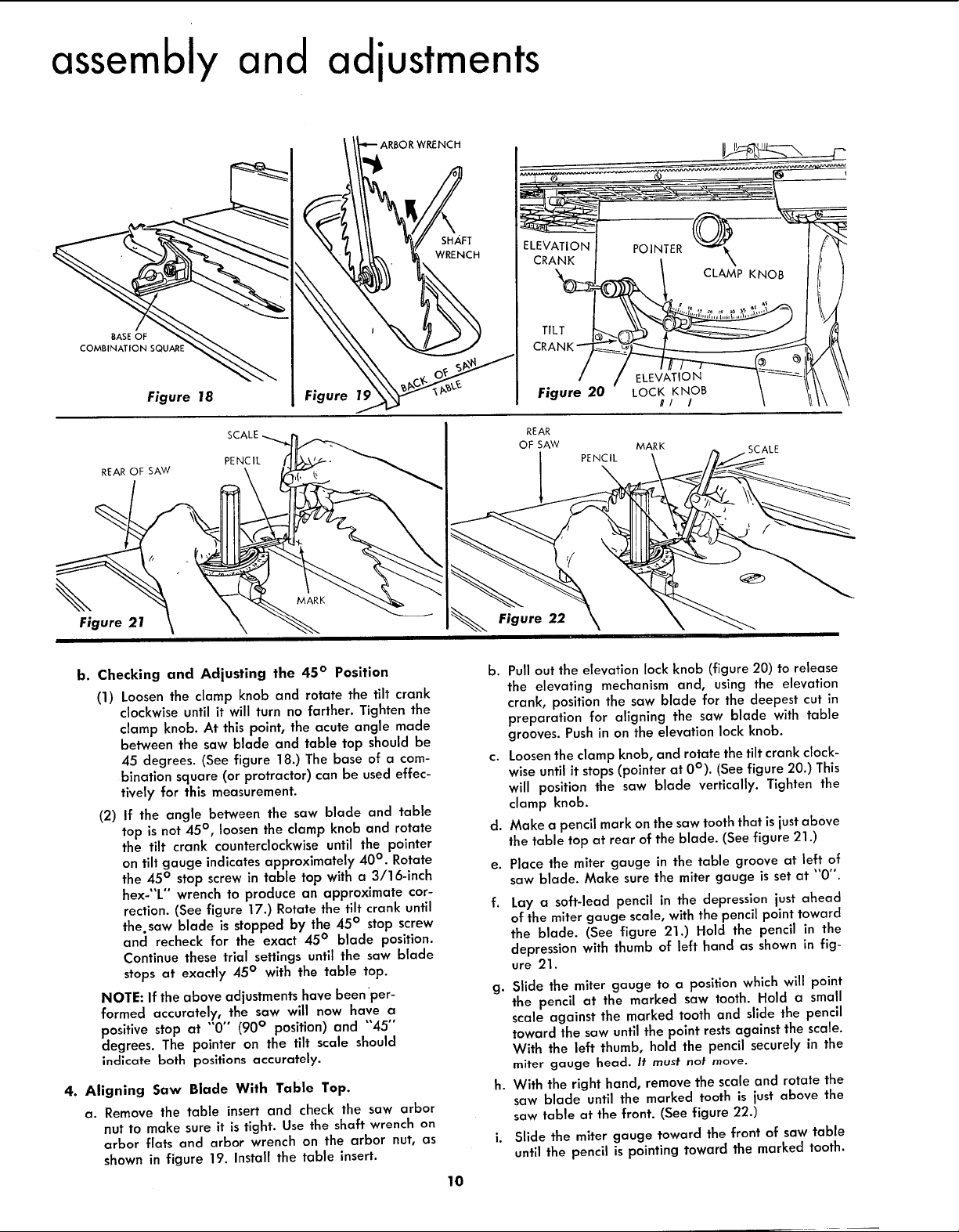
b. Checking and Adjusting the 45 ° Position
(1) Loosen the clamp knob and rotate the tilt crank
clockwise until it will turn no farther. Tighten the
clamp knob. At this point, the acute angle made
between the saw blade and table top should be
45 degrees. (See figure 18.) The base of a com-
bination square (or protractor) can be used effec-
tively for this measurement.
(2) If the angle between the saw blade and table
top is not 45 °, loosen the clamp knob and rotate
the tilt crank counterclockwise until the pointer
on tilt gauge indicates approximately 40 °. Rotate
the 45° stop screw in table top with a 3/16-inch
hex-"L" wrench to produce an approximate cor-
rection. (See figure 17.) Rotate the tilt crank until
the. saw blade is stopped by the 45 ° stop screw
and recheck for the exact 45° blade position.
Continue these trial settings until the saw blade
stops at exactly 45° with the table top.
NOTE: If the above adjustments have been 'per-
formed accurately, the saw will now have a
positive stop at "'0" (90 ° position) and "45"
degrees. The pointer on the tilt scale should
indicate both positions accurately.
4. Aligning Saw Blade With Table Top.
a. Remove the table insert and check the saw arbor
nut to make sure it is tight. Use the shaft wrench on
arbor flats and arbor wrench on the arbor nut, as
shown in figure 19. Install the table insert.
PENCIL
Figure
MARK
TILT
ELEVATION
Figure 20
REAR
OF SAW
Figure 22
b. Pull out the elevation lock knob (figure 20) to release
the elevating mechanism and, using the elevation
crank, position the saw blade for the deepest cut in
preparation for aligning the saw blade with table
grooves. Push in on the elevation lock knob.
c. Loosenthe clamp knob, and rotate the tilt crank clock-
wise until it stops(pointer at 0°). (See figure 20.) This
will position the saw blade vertically. Tighten the
clamp knob.
d. Make a pencil mark onthe saw tooth that is just above
the table top at rear of the blade. (See figure 21.)
e. Place the miter gauge in the table groove at left of
saw blade. Make sure the miter gauge is set at "0".
f.
Lay a soft-lead pencil in the depression just ahead
of the miter gauge scale, with the pencil point toward
the blade. (See figure 21.) Hold the pencil in the
depression with thumb of left hand as shown in fig-
ure 21.
g. Slide the miter gauge to a position which will point
the pencil at the marked saw tooth. Hold a small
scale against the marked tooth and slide the pencil
toward the saw until the point restsagainst the scale.
With the left thumb, hold the pencil securely in the
miter gauge head. It must not move.
h. With the right hand, remove the scale and rotate the
saw blade until the marked tooth is just above the
saw table at the front. (See figure 22.)
i. Slide the miter gauge toward the front of saw table
until the pencil is pointing toward the marked tooth.
10
PENCIL
LOCK KNOB
//! /
MARK
SCALE
 Loading...