

Craftsman 113298720 Owner’s Manual

[
Save ThisManual
For F_ure R_erence
owners
manual
MODEL NO.
113.298720
SAW WiTH LEGS
TWO CAST iRON
TABLE EXTENSIONS
MOTOR AND
QUICK RELEASE
RiP FENCE
Serial
Number
Model and serial
number may be found
at the left-hand side
of the base.
You should record both
model and serial numoer
in a safe place for
future use.
CAUTION:
Read GENERAL
and ADDITIONAL
SAFETY
INSTRUCTIONS
carefully
IO-INCH TABLE SAW
. assembly
. operating
e repair parts
Sold by SEARS,
Part No SP5!16
ROEBUCK AND CO., Chicaqo, IL. 60684 U.S.A.
P_irqed in US.A.

FULL ONE YEAR 'WARRANTY ON CRAFTSMAN TABLE SAW
If within one year from the date of purchase, this Craftsman Table Saw fails due to a defect in
material or workmanship, Sears will repel r it,free of charge. This warranty applies only while
this product is in use in the United States.
WARRANTY SERVICE IS AVAILABLE BY SIMPLY CO NTACTI NG THE NEAREST SEARS
SERVICE CENTER/DEPARTMENT THROUGHOUT THE UNITED STATES.
This warranty gives you specific legal rights, and you may also have other rights which vary
from state to state.
SEARS, ROEBUCK AND CO,, Dept. 698/731A, Sears Tower. Chicago, IL 60684
SAFETY INSTRUCTIONS FOR TASLE SAW
Safety is a combination of common sense, slaying
alert and knowing how your table saw works. Read
this manual to understand this saw.
BEFORE USING THE SAW:
WARNING: TO AVOID MISTAKES THA'Ir L;OULD
CAUSE SERIOUS, PER MANENT INJURY, DO NOT
PLUG THE SAW INUNTIL THE FOLLOWING STEPS
HAVE BEEN SATISFACTORILY COMPLETED:
1. Assembly and alignment (See pages9 -21 ).
2. Learn the use and function of the ON-OFF switch,
guard, spreader, anti-kickback device, miter gauge, 7.
fence, table insert and blade elevation and bevel
controls. (See page 22)
3. Review and understanding of all safety instructions
and operating procedures in this manual.
4. Review of the maintenance methods for this saw. 1. Inspect your saw.
(See page 41) a. To avoid injury from accidental starting, unplug
Read the following DANGER label found on the front of the saw, turn the switch off and remove the
the saw: switch key before raising or removing the
DANGER I FOR YOUR OWN SAFETY:
REA, D AND UNDERSTAND OWNERS MANUAL BEFORL;. OPERATING MACHINE
2 USE_;AWBLAOEGIJARDFOR ''THRUSAWING' 6 DO NOT PERFORM _) _ _E_
3 _(E[PHANOS;OUY OF PATH OF SAWBLAOE ? NEVERREACHAROUNDOROVEflSAWBLAD_
4 IJSE A "pUSH _'r_CK' WIltON R_:OIJIR_O
W_RNI_G: 'J_.£ 12o VOLT I$ _.MP BRANCH CIrCUiT AND UE>E1_ AMP TIMI_ DEL_,V FUSE
WHEN INSTALLING OR MOVING THE SAW:
1. AVOID DANGEROUS ENVIRONMENT. Use the
saw in a dry place protectedfrom rain. Keep work
2. To avoidinjury from unexpected saw movement:
b. Support the saw so the table is level and the
saw does not rock.
C Bolt the saw to the floor if ittends to stip walk;
or slide during normal use. ,
d. When Using table extensions Over24;'wide _n
any side of ;_hesaw, bo tthe saw to the floor6r
prop Upthe outer end" of the extension from
the floor to keep the saw from tipping,
3 put the saw where neither operators or bystand-
ers must stand in line with the saw blade.
4. 'GROUND THE SAW- This saw has an approved
3-conductor cord and a 3-prong grounding type
plug. The plug fits grounding type outlets design-
ed for 120 volt 15 amp circuits. The green
conductor in the cord is the grounding wire. To
avoid electrocution, NEVER connect the green
wire to a live terminal.
5. To avoid injury from electrical shock, make sure
your fingers do not touch the plug's metal prongs
when plugging in or unplugging the saw.
6. To avoid back n.ury, get help or use recom-
mended casters when you need to move the saw.
Always get help if you need to lift the saw. Hold
the saw close to your body. Bend your knees so
you can lift with your legs, not your back.
NEVER STAND ON TOOL. Serious injury could
occur if the tool t_ps or you accidentally hit the
cutting tool. Do not store anything above or near
the tool where anyone might stand on the tool to
reach them.
BEFORE EACH USE:
guard, changing the cutting tool. changing
the setup or adjusting anything.
b. Check for alignment of moving parts, binding
of moving parts, breakage of parts, mounting,
and any other conditions that may affect the
way it works. If any part is missing, bent, or
broken in anyway, or any electrical parts don't
work properly, turn the saw off and unplug the
saw.
c. Replace damaged, missing, or failed parts
before using the saw again.
d. Use the sawblade guard, spreader, and anti-
kickback pawls for any thru-sawing (wher)ever
the blade comes through the top of the work-
piece). Make sure the pawls work properly.
Make sure the spreader is in line with the
sawblade.
e. REMOVE ADJUSTING KEYS AND
WRENCHES. Form habit,of checking for and
removing keys and adjusting wrenches from
tool belt;re turning it on: ....
f. To avoid injury from jams, slips or thrown pieces
(kickback an(Jthrowback)_
1. USE ONLY RECOMMENDED ACCESSO:
R|ES. Follow the instructions that come with
the accessories. Consult the owners manual
!or recommended accessories. The use of
improper accessories may cause risk of injury
to persons.

2. Choose the right blade orcutting accessory
for the material and the type of cutting you
plan to do.
3. Never use grinding wheels, abrasive cut-off
wheels, friction wheels (metal slitting
blades) wire wheels or buffing wheel. They
can fly apart explosively.
4. Choose and inspect your cutting tool care-
fully.
a. To avoid cutting tool failure and thrown
shrapnel (broken pieces of blade), use
only 10" or smaller blades or other cutting
tools marked for speeds of 3450 rpm or
higher.
b. Always use unbroken, balanced blades
designed to fit this saw's 5/8" arbor.
c. When thru-sawing, (making cuts where
the blade comes through the workpiece
top) always use a 10 inch diameter blade.
This keeps the spreader in closest to the
blade.
d. Do not overtighten arbor nut. Use arbor
wrenches to "snug" it securely.
e. Use only sharp blades with properly set
teeth. Consult a professional blade sharp-
ener when in doubt.
f. Keep blades clean of gum and resin.
5. Adjust table inserts flush with the table top.
NEVER use the saw without the proper
insert.
6. Make sure all clamps and locks are tight
and no parts have any excessive play,
2. KEEP WORK AREA CLEAN
a. Cluttered areas and benches invite accidents,
Floor must not be slippery from wax or
sawdus_
b. To avoid burns or ott_er fire damage, never use
the saw near flammable liauids, vapors or
gases.
Plan ahead to protect your eyes, hands, face.'
ears.
a. To avoid injury, don't do layout, assembly, or
setup work on the table while the blade is
spin ning. It could cut or throw anything hitting
the blade.
AVOID ACCIDENTAL STARTING - Make sure
switch is "OFF" before plugging saw in.
Plan your work
1. USE THE RIGHT TOOL - Don't force tool or
attachment to do a job it was not designed for.
2. Dress for safety:
- Do not wear loose clothing, gloves, neckties
or jewelry (rings, wristwatches). They can get
caught and draw you into moving parts.
- Wear nonslip footwear.
- Tie back long hair.
- Roll long sleeves above the elbow
- Noise levels vary widely. To avoid possible
hearing damage, wear ear plugs or muffs
when using saw for long periods of time.
- Any power saw can throw foreign objects into
the eyes. This can cause permanent eye
damage, Wear safety goggles (not glasses)
that comply with ANSI Z87.1 (shown on pack-
age). Everyday eyeglasses have only impact
resistant lenses. They are not safety glasses.
Safety goggles are available at Sears retail
catalog stores. Glasses or goggles not in
compliance with ANSI Z87,1 could seriously
hurt you when they break.
WEAR YOUR
- For dusty operations, wear a dust mask along
with the safety goggles.
3. Inspect your workpiece. Make sure there are no
nails or foreign objects in the part of the work-
piece to be cut.
4. Plan your cut toavoid KICKBACKSand THROW-
BACKS - when a part or all of the workpiece
binds on the blade and is thrown violently back
toward the front of the saw:
- Never cut FREEHAND: Always use either a rip
fence, miter gauge or fixture to position and
guide the work. so it won't twist, bind on the
blade and kickback.
-Make sure there's no debris between the
workpiece and its supports.
- When cutting irregularly shaped workpieces,
plan your work so it will not slip and pinch the
blade:
- A piece of molding, for example, must lie
flat or be held by a fixture or jig that will not
let it twist, rock or slip while being cut, Use
jigs. fixtures where needed to prevent work-
piece shifting.
- Use a different, better suited type of tool for
work that can't be made stable.
- Use extra caution with large, very small or
awkward workpieces:
-Use extra supports (tables, saw horses,
blocks, etc.) for any workpieces large
enough to tip when not held down to the
table top. NEVER use another person as a
substitutefor a table extension, or as addi-
tional support for a workpiece that is longer
or wider then the basic saw table, orto help
feed. support or pull the workpiece.
- Never confine the piece being cut oft. That
is, the piece NOT against the fence, miter
gauge or fixture. Never hold it. clamp it,
touch it, or use length stops against it. tt
must be free to move. If confined, it could
get wedged against the blade and cause a
kickback or throwback.

- Never cut more than one workpiece at a
time.
- Never turn your table saw "ON" before
clearing everything except the workpiece
and related support devices off the table.
Plan the way you will push the workpiece through.
- NEVER putt the workpiece through. Start and
finish the cut from the front of the table saw.
- NEVER put your fingers or hands in the path of
the sawblade or other cutting tool.
- NEVER reach in back of the cutting tool with
either hand to hold down or support the work-
piece, remove wood scraps, or for any other
reason.
- Avoid hand positions where a sudden slip could
cause fingers or hand to move into a saw blade or
other cutting tool.
- DON'T OVERREACH. Always keep good footing
and balance.
- Push the workpiece against the rotation of the
blade. NEVER feed material into the cutting tool
from the rear of the saw.
- Always push the workpiece all the way past the
sawblade.
- As much as possible, keep you r face and body to
one side of the sawblade, out of line with a
possible kickback or throwback.
- NEVER turn the saw "ON" before clearing the
table of all tools, wood scraps, etc.. except the
werkpiece and related feed or support devices
for the cut planned.
WHENEVER SAW IS RUNNING
WARNING: DON'T LET FAMILIARITY (GAINED
FROM FREQUENT USE OF YOUR TABLE SAW)
CAUSE A CARELESS MISTAKE. ALWAYS
REMEMBER THAT A CARELESS FRACTION OF A
SECOND IS ENOUGH TO CAUSE A SEVERE
INJURY.
1. Before actually cutting with the saw watch it
while it runs for a short while. If it makes an
unfamiliar noise or vibrates a lot, stop immedi-
ately. Turn the saw off. Unplug the saw. Do not
restart until finding and fixing the problem.
,2. Make sure the top of the arbor or cutting tool
turns toward the front of the saw.
3. Set the cutting tool as low as possible for the cut
you're planning.
4. KEEPCHILDREN AWAY. All visitors should be
5. Let the blade reachfull speed before cutting.
6. DON T FORCE TOOL. It will do the job bette
and,safer at its designed rate. Feed the workpiece
into the blade only fast enough to let it cut While cutting
without bogging down or binding. -To avoid kickbacks and slips into the bade
c. Wait for all moving parts to stop.
d, Check blade, spreader and fence for proper
alignment before starting, again.
8. To avoid throwback of small, cut off pieces:
a. Use the guard assembly.
b. To remove pieces trapped inside the guard:
1. Turn saw off.
2. Remove switch key.
3. Unplug saw.
4. Wait for blade to stop before lifting the
guard.
additional instructions for
RiP TYPE CUTS
- NEVER use the miter gauge when ripping.
- Use a push stick whenever the fence is 2 to 6
inches from the blade. Use an auxiliary fence and
push block whenever the fence must be within 2
inches of the blade. (See "Basic Saw Operation
Using The Rip Fence" section.)
- Never rip anything shorter than 10" long.
-When using a push stick or push block, the
trailing end of the _)oard must be square. A push
stick or block against an uneven end could slip
off or push the work away from the fence.
- A FEATHERBOARD can help guide the work-
piece. See BASIC SAW OPERATION - USING
THE RIP FENCE. Always use featherboards for
any non-thru rip type cuts.
,__24"___
KERFS ABOUT !_,
5/16" APART IJ_
4-1/2 '' _''_'.'-''_ 5
Before Starting
-To avoid kickbacks and slips into the blade,
make surethe rip fence is parallel to the sawblade.
- Check the antikickback pawls. (See BASIC SAW
OPERATION - USING THE RIP FENCE.) The
pawls must stop a kickback once it has started.
Replace or sharpen antikickback pawls when
points become dul t.
- Plastic and composition (like hardboard) mater-
ials may be cut on your saw. However, since
these are usually quite hard and slippery, the
antikickback pawls may not stop a kickback.
Therefore, be especially careful in your set-up
and cutting procedures.
always push forward on the section of the work-

addiUonai instructions for
CROSS CUT TYPE CUTS
Before starting
- NEVER use the rip fence when crosscutting.
- An auxiliary wood facing attached to the miter
gauge can help prevent workpiece twisting and
throwbacks. Attach it to the holes provided.
Make the facing long enough and big enough to
support your work, Make sure, however, it will
not interfere with the sawblade guard.
- Use jigs or fixtures to help hold any piece too
small to extend across the full length of the miter
gauge face during the cut. This lets you properly
hold the miter gauge and workpiece and hetps
keep your hands away from the blade.
GLOSSARY OF TERMS FOR WOODWORKING
While cutting
- To avoid blade contact, always hold the miter
gauge as shown in the BASIC SAW OPERA-
TIONS - USING THE MITER GAUGE.
BEFORE LEAVING THE SAW
1. Turn the saw off.
2. Wait for blade to stop spinning.
3. Make workshop child-proof. Lock the shop. Dis-
connect master switches. Remove the yellow
switch key. Store it away from children and
others not qualified to use the tool.
4. Unplug the saw.
Anti-Kickback Pawls (AKB)
Device which, when properly maintained, is design-
ed to stop the workpiece from being kicked back at
the operator during ripping operations.
Arbor
The shaft on which a cutting tool is mounted.
Crosscut
A cutting or shaping operation made across the
width of the workpiece.
Dado
A non-through cut which produces a square sided
notch or trough in the workpiece.
Featherboard
A device which can help guide workpqeces during np
type operations.
Freehand
Performing a cut without using a fence, miter gauge,
fixture, hold down or other proper device to keep the
workpiece from twisting during the cut.
Gum
A sticky, sap based residue from wood products.
Heel
Misalignment of the blade.
Kerr
The amount of material removed by the blade in a
through cut or the slot produced by the blade in a
non-through or partial cut.
Kickback
An uncontrolled grabbing and throwing of the work-
piece back toward the front of the saw during a rip
type operation.
Leading End
The end of the workp_ece which during a r_p type
operation, is pushed into the cutting tool first.
Molding
A non-through cut which produces a special shape
in the workpiece used for joining or decorat on.
Push Stick
A device used to feed the workpiece through the saw
during narrow ripping type operations and help
keep the operator's hands well away from the blade.
Push Block
A device used for ripping type operations too narrow
to allow use of a push stick.
Rabbet
A notch in the edge of a workpiece.
Resin
A sticky, sap base substance that has hardened.
Ripping
A cutting operation along the length of the work-
piece.
Revolutions Per Minute (RPM)
The number ofturns completed by a spinning object
in one minute.
Sawblade Path
The area of the workpsece or table top directly in line
with the part of the workpiece which wil! be. or has
been, cut by the blade.
Set
The distance that the tip of the sawbJade tooth is
bent (or set) outward from the face of the blade.
Throw-Back
Throwing of pieces in a manner similar to a kickback.
Thru-Sawing
Any cutting operation where the blade extends
completely through the thickness of the workplece.
Trailing End
The workpiece end last cut bythe blade in a ripping
operation.
Workpiece
The item on which the cutting operation is being
done_ The surfaces of a workpiece are commonly
referred to as faces, ends, and edges.

MOTOR SPECIFICATIONS AN
This saw is designed to use a 3450 RPM motor onmy.
Do not use any motor that runs faster than 345,0
RPM, It is wired for operation on 110-120 volts, 60
Hz.. Alternating current. IT MUST NOT BE
CONVERTED TO OPERATE ON 230 VOLTS.
The Black and Red motor leads are connected to
qu_ck connect tabs "A" and "g" on terminal board.
WARNING: Do not change any of these connec-
tions with current on.
BLACK
POWER LEAD T_
POWER LEAD'---_ i
CAUTION: Do not use blower or washing machine
motors or any motor with an automatic reset
overload protector as their use may be hazardous.
For replacement motor refer to parts list in this
manual.
CONNECTING TO POWER SOURCE OUTLET
This saw must be grounded while in use to protect
the operator from electrical shock
If power cord is worn or cut, or damaged in any wa y,
have it replaced immediately.
If your saw is for use on less than 150 volts it has a
plug that looks like below.
3-PRONG PLUG
GROUNDING PRONG
3-PRDNG OUTLET
Plug power cord of fully assembled saw into 11 0-
120V properly grounded type outlet protected by" a
15-amp. time delay or Circuit-Saver fuse or ci rcuit
breaker.
IF YOU ARE NOT SURE THAT YOUR OUTLET iS
PROPERLY GROUNDED, HAVE IT CHECKED BY A
QUALIFIED ELECTRICIAN.
WARNING: DO NOT PERMIT FINGERS TO
TOUCH THE TERMINALS OF PLUG WHEN
INSTALLING OR REMOVING THE PLUG TO CPR
FROM THE OUTLET.
WARNING: IF NOT PROPERLY GROUNDED THIS
POWER TOOL CAN INCUR THE POTENTIAL
HAZARD OF ELECTRICAL SHOCK PARTICU-
LARLY WHEN USED, IN DAMP LOCATIONS, iN
PROX|MITY TO rk_,,,,_U'S NG, OR OUT OF I)OOR S.
IF AN ELECTRICAL SHOCK OCCURS THERE IS
THE POTENTIAL OF A SECONDARY HAZARD
SUCH AS YOUR HANDS CC)NTACTING THE
SAWBLADE.
This saw is equipped with a 3-conductor cord and
grounding type plug which has a grounding prong,
approved by Underwriters' Laboratories and the
Canadian Standards Association. The ground
REEN
"_ GROUND SCREW
IB RED
GROUNDED
D
ELECTRICAL REQUIREMENTS
conductor has a green _ug _ nd _sattached to the tOOt
housing a[ one _nd and _o the ground prong mtrle
attachrnent plu_ at tr_e otf_e _end
Th_s p_ug rerau_res a rnat_ng 3-cunductor grounded
type outlet as sr_owf_
If the outlet you are planmng tc _Jsefor this saw is of
the two prong type DO NOT REMOVE OR ALTER
THE GROUNDING PRONG tN ANY MANNER. Use
an adapter as strewn and a_ways connect the
grounding _ug to a known ground
it _s recommended that y'ou have a qualified
electrician replace fh_ TWO prong outlet with a
properly grounded THREE ;_rong outlet.
A temperat, ado pter _s snown De_(_WtSavaliab;e for
connechnq ptugs to 2-prong receptacles. The green
ground ing Iug e ×ter_din(_ f torn the aoa [)terrn us| be
corlr/f_,c|_(] t_°) a _)ermanen! _!"©_rltJ S(;Ctq B5 [o a
proper_¥ _rt-_unded o(J'Je_ D()×
A temporary a(]aDter as _uusrrate(; m avadabte for
connecting plugs to 2-_)ronq receptacles The
ternp_}rarv adapt_:l ShOUld De use(] only _,n_tl a
properW _gro_Jnded out_et can be m_taHed oy a
qt_alified elec[nc_arl
GROUNDING LUG
3PRO_NG _ " . _,_-. CONNECTED TD A
PLUG "* I' ;_")_i
ADAPTER
MAK[ SURE THIS tS
KNOWN GROUND
WARNING: THE GREEN GROUNDING LUG
EXTENDING FROM THE ADAPTER MUST BE
CONNECTED TO A PERMANENT GROUND
SUCH AS TO A PROPERLY GROUNDED OUTLET
BOX, NOT ALL OUTLET BOXES ARE PROPERLY
GROUNDED.
If you are not sure that your outlet box is properly
grounded, have it checked by a qualified electrician.
NOTE: The adapter dlustrated is for use only if you
already have a properly grounded 2-prong
receptacle
The use of any extension cord will cause some loss
of power_ To keep this to a minimum and to prevent
over-heating and motor burn-out use the table
below to determine the mm_mum w_re size (A.W.G.}
extension cord Use only 3 wire extension cords
which have 3 prong grounding type plugs and 3-
pole receptacles which will accept the plug on the
S_W.
1 H.P. MOTOR 110-120V
Extension Cord Length Wire Size A.W.G.
0-25 Ft...................... 16
26-50 Ft ..................... 14
51-100 FI .................... 12
CHECK MOTOR ROTATION
WARNING: FORYOUROWN SAFETY, MAKESURE
PLUG IS NOT CONNECTED TO POWER SOURCE
OUTLET WHEN CHANGING MOTOR ROTATION.
The motor must rotate CLOCKWISE when viewed from
the shaft end to which you wilt mount the pulley. (See
page 18.) tf it does not, change the direction according
to the instructions furnished with the motor.
CONTENTS
WARRANTY ............................................................... 2
SAFETY INSTRUCTIONS FOR TABLE SAWS ......... 2
Rip Type Cuts ........................................................ 4
Cross Cut Type Cuts ............................................. 5
GLOSSARY OF WOODWORKING TERMS .............. 5
MOTOR SPECIFICATIONS AND ELECTRICAL
REQUIREMENTS .................................................. 6
UNPACKING AND CHECKING CONTENTS ............ 7
Tools Needed ......................................................... 7
List of Loose Parts ................................................. 8
AS SEM SLY ................................................................ 9
Installing Handwheels ............................................ 9
Checking Table Insert ............................................ 9
Checking Blade Squareness to Table ................... 9
Assembling Steel Legs ........................................ 10
Mounting Saw ...................................................... 10
Attaching Table Extensions ................................. 11
Mounting Switch .................................................. 12
Installing Rip Fence Guide Bars .......................... 12
Aligning Rip Fence ............................................... 14
Adjusting Rip Scale Pointer ................................. 16
Installing Blade Guard ......................................... 16
Mounting the Motor .............................................. 18
installing Belt Guard ............................................. 20
Plugging in Motor ................................................. 21
GETTING TO KNOW YOUR SAW .......................... 22
On-Off Switch ....................................................... 22
Elevation Handwheel ........................................... 23
Tilt Handwheel ................................................... 23
Tilt Lock Handle ................................................... 23
Rip Fence ............................................................ 23
Miter Gauge ......................................................... 23
Blade Guard ......................................................... 23
Table Insert .......................................................... 23
Removing and Installing Sawblade ...................... 24
Exact-I-Cut ........................................................... 24
BASIC SAW OPERATION ....................................... 25
Work Helpers ....................................................... 25
Safety Instuctions for Basic Saw Operation ......... 26
Using the Miter Gauge ......................................... 29
Crosscutting ..................................................... 29
Repetitive Cutting ............................................ 30
Miter Cutting .................................................... 30
Bevel Crosscutting ........................................... 31
Compound Miter Cutting .................................. 31
Using the Rip Fence ............................................ 31
Ripping ............................................................ 32
Bevel Ripping .................................................. 32
Using Featherboards for Thru-Sawing ............ 32
Resawing ......................................................... 35
Cutting Panels ................................................. 35
Using Featherboards for Non-Thru Sawing .....35
Rabbeting ........................................................ 36
Ploughing and Molding .................................... 36
Dadoing ........................................................... 36
Melding Cutting ................................................ 37
ADJ USTM ENTS ....................................................... 37
Miter Gauge ......................................................... 37
Heeling Adjustment or Parallelism of Sawblade
to Miter Gauge Groove ................................... 38
Blade Tilt or Squareness of Blade to Table ......... 39
Tilt Mechanism ..................................................... 41
MAINTENANCE ....................................................... 41
LUBRICATION ......................................................... 42
RECOMM ENDED ACCESSORIES ........................ 42
TFIOUBLESHOQTING ............................................. 43
REPAIR PARTS ....................................................... 45
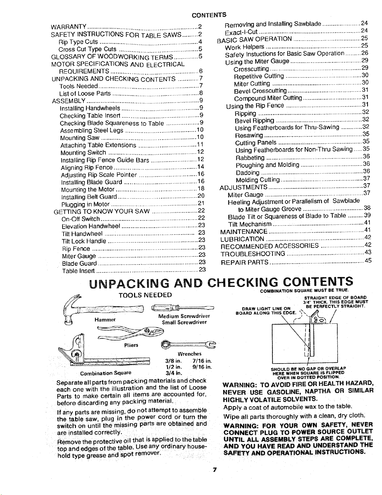
UNPACKING
AND CHECKING CONTENTS
NEEDED
_- ,_-,=-- _ Medium Screwdriver
(_ Hammer Small Screwdriver
__ .................... Wrenche
3/8 in. 7/16 in.
Combination Square 3/4 in.
1/2 in. 9/16 in.
Separate all parts from packing materials and check
each one with the illustration and the list of Loose
Parts to make certain all items are accounted for,
before discarding any packing material.
If any parts are missing, do not attempt to assemble
the table saw, plug in the power cord or turn the
switch on until the missing parts are obtained and
are installed correctly.
Remove the protective oil that is applied to the table
top and edges of the table, Use any ordinary house-
hold type grease and spot remover.
COMBINATION SOUARE MUST BE TRUE.
STRAIGHT EDGE OF BOARD
3/4" THICK. THIS EDGE MUST
DRAW LIGHT LINE ON
BOARD ALONG THIS EDGE. '_
BE PERFECTLY STRAIGHT.
I
L_
SHOULD BE NO GAP OR OVERLAP
HERE WHEN SQUARE IS FLIPPED
O_R tNDOTTEDPosmoN.
WARNING: TO AVOID FIRE OR HEALTH HAZARD,
NEVER USE GASOLINE, NAPTHA OR SIMILAR
HIGHLY VOLATILE SOLVENTS.
Apply a coat of automobile wax to the table.
Wipe all parts thoroughly with a clean, dry cloth.
WARNING: FOR YOUR OWN SAFETY, NEVER
CONNECT PLUG TO POWER SOURCE OUTLET
UNTIL ALL ASSEMBLY STEPS ARE COMPLETE,
AND YOU HAVE READ AND UNDERSTAND THE
SAFETY AND OPERATIONAL INSTRUCTIONS,

LIST OF LOOSE PARTS
item Part Name Qty.
A Blade Guard and Spreader ............... 1
B Rip Fence. ............................. 1
C Owners Manual . ....................... 1
D Cast Iron Table Extensions .............. 2
E Miter Gauge ........................... 1
F Rip Fence Guide Bar Rod ................ 1
J Rip Fence Guide Bar with Rip Scale
(Front) .............................. 1
S Support, Motor Base .................... 1
V Rip Fence Guide Bar (Rear) .............. 1
AJ Leg ............................... 4
AK Side Stiffener ........................... 2
AL End Stiffener ........................... 2
AM Motor ................................. 1
Bag of Loose Parts ..................... 2
Bag of Loose Parts
(Containing the Following Items)
H Outlet. 0n/0ff with Key .................. 1
K Handwheel ............................ 2
Bag of Loose Parts ..................... 3
Bag of Loose Parts
(Containing the Following Items)
N Belt and Pulley Guard ................... 1
0 Belt Guard Clip "S' . ......................
P Screw, Pan Hd. 10-32 x 1/2" Long ........ 3
Q Support, Belt Guard ..................... 1
R Belt Guard Support Bracket .............. 1
Bag of Loose Parts No. 62750
(Containing the Following Items)
G Wrench: Arbor ..; ............. 1
L Belt, V 1/2 x41 .................. ...
M Pulley, 1/2" dia. with 5t8" Bore... ........
1 AA Nut, Hex 1/4-20 ................. 2
1 AC Carriage Bolt. 5/16-18 x 3/4 ............ 4
T Spreader, Rod.. ........................ 1
U Blade Guard Support wlScrew ........... 1
W Spreader Support .......: ........ _.... 1
Bag of Loose Parts No. 62751 ............ 1
Bag of Loose Parts No. 507780
(Containing the Following Items)
Z Screw, He;<Hd; 5/16-t8 x 1-1/4 ... : ...... 8
AB Lockwasher. External 5/16 .............. 8
Z AA
AO "_
AG AH
AL
Item Part Name
AN Nut. Heavy Hex Jam 5/16-18 ............. 8
A0 Washer. 11/32 x 11t16 x 1/16 ............ 8
Bag of Loose Parts No 62752
(Containing the Following Items)
Z Screw. Hex Hd. 5/!6-18 x 1-1/4 .......... 4
AA Nut, Hex 1/4-20 ........................ 24
AA Nut, Hex Heavy Jam 5/!6-18 ............. 4
AB Lockwasher External 5/16 .............. 4
AB Lockwasher External 1/4 ............... 24
AN Nut. Hex Jam 1/2-13 .................... 8
A0 Washer, 11/32 x 11/16x t/16 ............ 8
AP Screw, Truss Hd 1/4-20 x 5/8 ............ 24
AQ Foot Leveling 1/2 ...................... 4
Bag of Loose Parts No. 62751
(Containing the Following Items)
X Wrench, Hex"L" 1/8 ....................
X Wrench. Hex "L" 3/32 ................... 1
X Wrench. Hex"L" 5/32 ................... 1
Y Nut, Self-Threading ..................... 2
Z Screw. Hex Hd. 5/16-18 x 5/8 in. long ..... 3
Z Screw, Hex Hd. 5/16-18 x 3/4 in. long ...... 2
Z Screw, Hex Hed. 5/16-18 x t n. long ...... 4
g Screw. Hex Hd. 5/16-18 x 1-314 in. long .. 2
Z Screw, Hex Hd. 114-20 x 518 in. long ...... 2
AA Nut, Heavy Hex Jar_ 5/16-18 ............. 10
AI) Spacer, Rip Fence Guide Bar ............. 2
AE T_eWire ........ i ...................... 2
AF Screw; Pan Hd 10-32 x 3/4 ............ 2
AG Screw, Thurnb5/16-18x 1 ............... 1
AB Lockwasher External #10 ....... 2
A8 Lockwasher External 1/4 .............. 2
AB Lock_vasher,:External 5/16 .......... 12
A0 W'asher. 21/64 x 5/8 x 1/16 .............. 2
8

ASSEMBLY
Before mounting the saw on legs, a stand or abench,
the Table Insert and Blade Squareness must be
checked at this time.
iNSTALLING HANDWHEELS
1. Line up FLAT SPOTS on shaft and hardwheel,
push handwheel onto shaft. Install screw and
Iockwasher to lock handwheet on shaft.
CHECKING TABLE iNSERT
2. Insert should be flush with table top, Check as
shown. Loosen flat head screw that holds insert
and adjust the four set screws as necessary.
Tighten flat head screw. Do not tighten screw to
the point where it deflects the insert.
.OCKWASHER
/
10-32 x 314 IN.
PHILLIPS
ELEVATION HEAD SCREW
HANDWHEEL TILT HANDWHEEL
3/32 IN
SETSCREW WRENCH
= =
3. To remove insert.
A) Loosen Screw
B) Lift insert from front end, and pull toward
front of saw.
4. To replace insert.
Place insert into insert opening in table and push
toward rear of saw to engage spring clip and until
keyslot m insert will drop over screw. Tighten
screw.
Do not tighten screw to the point where it will
deflect the insert.
CHECKING BLADE SQUARENESS TO
TABLE
iMPORTANT: BLADE must be SQUARE (90° ) to
TABLE, in order to proceed with assembly.
1. Turn ELEVATION handwhee! clockwise until
blade is up as high as it will go.
2. Check for BLADE SQUARENESS... if blade is
not square to table, adjust it at this time.
NOTE: The combination square must be "true"
-see start of "Un packing and Checking Contents"
section on page 6 for checking method.
Refer to "BLADE TILT, OR SQUARENESS OF
BLADE TO TABLE" adjustment on page 34.
FLAT HEAD _"__ //
MAKE SURE SQUARE
iS NOT TOUCHING
TiP OF TOOTH
/

ASSEMBLING STEEL LEGS
From among the loose parts, find the following
Hardware:
24 Truss Head Screws, 1/4-20 x5/8 in. long (top of
screw is rounded)
24 Lockwashers, 1/4 in, External Type (approx.
dia. of hote 1/4 in.)
24 Hex Nuts, 1/4-20 (approx. dia. of hole 1/4 in.)
8 Hex Nuts, 1/2-13 (approx. dia. of hole 1/2 in.)
4 Leveling feet
Assemble the legs as shown..
1. Insert the Truss Head Screws through the holes
in the legs, then through the holes in the stiffen-
ers MAKE SURE THE SCREWS TO THROUGH
THE HOLES IN THE SIDE STIFFENERS
MARKED "X'"
2. Install the Iockwashers.. _screw on the nuts but
do not tighten until completely assembled.
3. Install leveling feet.
.-,+_71!2 IN. HEX NUTS
......... LEVELING FOOT
MOUNTING SAW
1. From among the loose parts, find the following
hardware:
4 Hex Head Screws, 5/16-18 x 1-1/4 in. long.
4 Hex Nuts, 5/16-18 (approx. dia. of hole 5/16 in.)
4 Lockwashers, 5/16 in. External Type (approx.
dia. of hole, 5/16 in.]
8 Flat Washers, (dia. of hole 11/32 in.)
2. Ptase saw on legs so that holes in bottom of saw
line up with holes in top of legs.
3. Install screws, washers, Iockwashersand nuts as
shown.
tf you mount the saw on any other bench, make sure
that there is an opening in the top of the bench the
same size as the opening nthe bottom of the saw so
that the sawdust can drop through. Recommended
working height is 33 to 37 inches from the top of the
saw table to the floor.
SAW BASE ]_[
HEXHEAOSC.EW
FLAT WASHE R'----_ _ tl
END f _ ""
STIFFENER--_L
FLAT WASHER ]/
_--................. 11-1/4 .....................
,o,I
............
'_{' OPENIN G
\, /
I
13
16 _\
/
;/ \
7/16 DIA. HOLES
/
/
13
\
Q__3_
IO
2-3/4
FRONT OF SAW
112
NOTE: All dimensions in inches

ATTACHING AND ASSEMBLING
TABLE EXTENSIONS
From among the loose parts find the following
hardware: (Quantity indicated is for 2 extensions)
HARDWARE FOR INSTALLING
EXTENSIONS TO SAW TABLE
Ref.
No. Description Qty,
1 Hex Hdl Screw, 5/16-18 x 1-1/4 ...... 8
2 Flat Washer (Dia: of Hole 11/32) ..... 8
3 External Lockwasher, 5/16 ........... 8
4 He× Nut, 5/16-18 .................... 8
1. |nsert four (4) 5/16-18 x 1-1/4 in. tong screws
through holes in each EXTENSION.
2. Position extension against table so screws
extend through holes in table.
3_ Install flat washer, Iockwashers, and nuts on the
screws... DO NOT TIGHTEN.
4. Line up the rear edge of extension with the rear edge
of the table. Line u0 top sudace of the extension with
the top of the table at the locations indicated by the
"X"s (see illustration). Use a combination square to
line-up these edges. SLIGHTLY TIGHTEN nutswith
a 9/16" wrench.
5. Ifadjustment is necessary, you should tap the exten-
sion into position using a hammer and a block of
wood. Make sure the rear edge of extension is lined
up withthe rear edge ofthe table. Thenfirmlytigh
nuts.
6. Repeatthe sameprocedureto installthe otherexten-
sion.
LOCK OF WOOD "
\
_'_ JCHECK WITH SQUARE
AT 2 PLACES
MARKED WITH "X"
11

MOUNTING SWITCH
1. From among loose parts find the following:
2 Hex Head Screws, 5/16-18 x 3/4 in. long
2 Flatwashers (dia. of hole 21/64 in.)
2 External Lockwashers
2 Hex Nuts, 5/16-18
2. Insert two 3/4 inch screws through two flat
washers then through holes in switch.
3. Insert screws through holes eight and ten in front
fence guide bar as illustrated
4. Install two Iockwashers and nuts Tighten nuts,
JAM NUT
5116-18
t_---_ WASHER
I
HEX HEAD SCREW
5/16-18 x 3/4 IN.
INSTALLING RiP FENCE GUIDE BARS
1. From among the loose parts find the following
hardware:
2 Hex Head Screws. 5/16-18 x 1-3/4 in. long
2 Hex Head Screws, 5/16-18 x 1 in. long
4 External Lockwashers, 5/16 in.
(approx. dia. of hole 5/16 in.)
4 Hex Nuts, 5/16-18
(approx. dia. of hole 5/16 in.)
2 Spacers. 3/4 in. dia. x 1/2 in. long
2 Self-threading nuts
1 Fence Guide Bar Rod
2. Lay guide bars on saw table.
NOTE: The various holes in the bar allows them
to be positioned on this saw and also makes
them adaptable to other models.
3. Insert a 1-3/4 inch long screw through the
THIRD hole IN THE FRONT BAR as illustrated
... Insert another 1-3/4 inch long screwthrough
the SEVENTH hole in bar.
4. Place spacers on screws,
5. Turn front bar end for end and insert bolts
through holes in middle and on right sides of
front of saw table as illustrated . . . install
Iockwashers and nuts. DON'T SCREW NUTS
ON ALL THE WAY, just get them started on the
screws.
7TH HOLE
3RD HOLE
LEFT SIDE OF
FRONT GUIDE BAR
(GUIDE BAR IS TO BE
TURNED END FOR ENE
AFTER SCREWS ARE
INSTALLED)
HEX HEAD
SCREW
5/16-18 x 1-3/4 IN
4TH OR 5TH 2ND HOLE
_k"_ SELF-THREAD|NG NUT HOLE
6. Inse[t 1 in. long screws in SECOND and _ - /"
FOURTH or FI FTH holes of rear bar and attach
to table the same way as front bar.
7. Insert ends of FEKICE GUIDE BAR ROD F
through holes in bars as illustrated. BAR ROD
NOTE: The ends of the ROD are not threaded ...
the SELl: THREADING NUTS wil! cut threads
on the rod as they are screwed on. Just start nuts c
onto ends of rod.
]2

8. Hold rod with one hand and with a 1/2 in. wrench
or pliers start screwing on ONE of the nuts only A
TURN OR TWO... screw on other nut the same
way.
9. Using TWO 1/2 in. wrenches or pliers tighten
both of the nuts.
10. Slide the bars so that screws are in the MIDDLE
of the slotted holes.
11, Position rip fence over miter gauge groove,
holding up the rear end while engaging front end
with bar lower fence onto table.
12. Raise blade all the way up.
13. Carefully move fence against blade.
14. Move front bar until "0" mark on rip scale is
approximately at tip of pointer.
15. Move FRONT bar upwards until fence is approxi-
mately 1/32 in. above table.., tighten screw at
left end of bar.
NOTE: Fold a piece of newspaper making 8
thicknesses and place between rip fence and
table to act as a spacer. This wil! hold the fence
off of the table approx. 1/32 in.
16. Adjust rear bar so that the fence is approximately
1/32 in. above table make sure it is square with
fence guide bar rod.., tighten screw at end of
bar.
17. Move fence to RIGHT edge of table.., make sure
t is approx. 1/32 in. above table at front and rear
and tighten screws.
8 THICKNESSES
OF PAPER
8 THICKNESSES
OF PAPER
13

ALIGNING RiP FENCE
The fence should slide easily along the bars and
always remain in alignment (parallel to sawblade
and miter gauge grooves).
The alignment is maintained by aspring underneath
the fence which bears against the front guide bar.
TOmovethe fence, loosen the lock handle and grasp
the fence with one hand at the front.
For very close adjustments, grasp theguide bar with
both hands and move the fence with your thumbs.
SELF ALIGNING ADJUSTMENT
Place fence on saw but DO NOT LOCK IT.
Move the R EAR END of the fence slightly to the right
or left. , . when you release it, the fence should
"spring" back to its original position.
If i| does not, the spring pressure must be IN-
1. Looser, the screws.
2 Move Spring slightly toward front of fence.
\
14

If fence does not slide easily along the bars, the
pressure of the spring can be REDUCED.
1. Loosen the screws.
2. Move spring slightly toward rear of fence . . .
tighten screws.
WARNING: TO AVOID INJURY FROM JAMS OR
KICKBACK, BE SURE TO PROPERLY ADJUST AND
PUSH LOCK LEVER ALL THE WAY DOWN UNTIL
THE LEVER RESTS ON THE STOP BEFORE USING
THIS RIP FENCE.
RIP FENCE LOCK LEVER ADJUSTMENT
The ripfence lock lever when locked down, should hold
the rip fence securely, it should not be difficultto push
down and lock.
SPRING
SCREWS,
SLIDE SPRING TO
ADJUST PRESSURE
AD3USTING NUT
If lock lever does not lock fence securely...
1. Raise lock lever.
2. Tighten the aOjusting nut using a small screwdriver
until the lever, when locked, holds the rip fence
securely.
If lock lever is difficult to push down...
1. Raise lock lever.
2. Loosen the adjusting nut using a small screwdriver
until the lever is easy to push down and holds the rip
fence securely.
RiP FENCE ALIGNMENT ADJUSTMENT
The riptence must be PARALLEL with thesawblade and
MiterGauge grooves_..Move fence until it is along side
of groove. Do NOT LOCK IT. It should be parallel to
groove. If it is not;
1. Loosen the two "Hex Head Screws".
FENCE HEAD
HEX SCREWS
FENCE HEAD
2. Hold fence head tightlyagainst bar.., move end of
fence so that it isparallel withgroove.
3. Alternately tighten the screws.
4. Recheck alignment.
5. Repeat steps as needed.
\
\
15

ADJUSTING RiP SCALE POINTER
1. Turn ELEVATION HANDWHEEL clockwise untH
blade is up as high as it will go,
IMPORTANT: BLADE must be SQUARE (90 ° ) to
TABLE. in order to ALIGN rip fence.
2. Position fenceon right side of sawblade so that it
touches the sides of the teeth.., tighten lock
handle.
3. Loosen screw holding the pointer . . . adjust
pointer so that it points to "0" .. tighten screw.
NOTE: If you cannot adjust pointer so that it
points to "0", loose n the screws holding the fro nt
guide bar and move the guide bar.
INSTALLING BLADE GUARD
1_ From among the loose parts, find:
2 Hex Head Screws, 1/4-20 x 5/8 in. long
3 Hex Head Screws, 5/16-18 x 5/8 in. long
2 Hex Head Screws, 5/16-18 x 1 in. long
2 Hex Nuts, 1/4-20 (approx. dia. of hole 1/4 in.)
2 Lockwashers, 1/4 in. External Type
(approx. dia. of hole 1/4 in.)
2 Lockwashers, 5/16 in. External Type
(approx. dia. of hole 5/16 in.)
1 Thumbscrew
Blade Guard Support
Spreader Support
Spreader Rod
BLADE GUARD _,_ ''-_
SUPPORT 5/16-18
5/16ol 8 X: \
HEX HD.
SCREW
\
HEX HD.
_-K HANDLE
POINTER
2. Before installing theblade guard, you mustcheck the
5/16 IN.
LOCKWASHERS
heelingadjustment (parallelism of sawblade to miter
gauge groove). The procedure for making this check
and adjusting it are found inthe "Adjustments" sect ion
5/16-18 X 5/8 IN
HEX HD. SCREWS
of this manual. Refer to "Heeling Adjustment or
Parallelism ol Saw Blade to Miter Gauge Groove".
3. Lower the blade.
4. Screw the MOTOR BASE CLAMP SCREWS part
way into cradle. Screw the 5t16-18 x 5/8 inch Hex
Head screw into the blade guard support.
5. Attach BLADE GUARD SUPPORT... DO NOT
TIGHTEN SCREWS,
r
THUMB SCR EW//__
6 Insert SPREADER ROD intoSPREADER SUPPORT SPREADER
ti;thleP_nitlitsint° n°tch" Insert THUMBSCREW and sFRLFATcE
(INTO SUPPORT), SUPPORT
SPREADER
,,
 Loading...