

Cosmic ACDC12 User And Installation Manual

Before installing or using your solar air conditioner, please print and read
this manual carefully and keep it for future reference.
Please read this installation manual completely before installing the product. If the power cord is damaged,
replacement must be performed by authorized personnel only. Installation work must be performed in accordance
with the NEC and local codes. You should contact a licensed service technician for installation, repair, or maintenance.
Improper installation could damage the system and/or void the warranty and could result in injury, death, or property
damage.
.
Notice To Owner/Installer
This unit is designed for easy installation by an experienced person. It is
legal for a homeowner to install it, however we highly recommend using
a licensed HVAC technician for installation.
Legal Information About Self-Installing R410A Air Conditioners
Can a homeowner install this system?
Yes, a homeowner with a vacuum pump, proper training, and equipment can install this unit. Unless
you are experienced with installing air conditioners we recommend you hire a professional installer. The
person who installs the system must do all work in compliance with local building and electrical codes.
Are there any restrictions on the purchase of R410A refrigerants?
R410a is not an ozone-depleting substance. At this time the purchase of R410a refrigerant is not restricted
in the US. There is no technician certification requirement for those that purchase HFC refrigerants, such
as R-410a or R-134a. If you are not licensed, some local HVAC supply companies may refuse to sell you
R410a based on a misunderstanding of the law, or because they wish to discourage homeowners from
working on their own systems.
Are there any restrictions on the use of R410A refrigerants?
Yes, it is illegal to knowingly vent or release these refrigerants. The venting prohibition applies to
R410a, and all other HFC refrigerants, just as it does for ozone-depleting refrigerants like R-22.
Is EPA technician certification required to service R410A systems?
No, at this time EPA technician certification is not required in order to service R-410a systems.
Source: http://www.epa.gov/ozone/title6/phaseout/technicians_contractors_faq.html
ACDC12 Solar Air Conditioner
Heat Pump
CONTENTS
SAFETY PRECAUTIONS
Warning 2
Caution 2
Selecting installation location 3
Accessories 4
Indoor unit installation 5
Outdoor unit installation 7
Refrigerant pipe connection 8
Electrical work 9
Installation of the solar photovoltaic system 12
Evacuation with a vacuum pump 23
Safety and leakage check 24
Testing 25
Please Print & Read This Manual
Inside you will find many helpful hints on how to install and test the air conditioner properly.
CAUTION
Contact an authorized service technician for repair or maintenance of this unit.
Only allow a qualified person to install this unit.
The air conditioner is not intended for use by young children without supervision.
Young children should be supervised to ensure that they do not play with the air conditioner.
If the power cord is to be replaced, replacement work must be performed by authorized personnel only.
Installation work must be performed in accordance with local building and electrical codes.
1
SAFETY PRECAUTIONS
Read the follow SAFETY PRECAUTIONS carefully before installation.
Electrical work must be installed by a licensed electrician. Be sure to use the correct rating
and main circuit for the model to be installed.
Incorrect installation may cause injury, death, or damage.
Please pay attention to the following indications.
WARNING
This symbol indicates the possibility of death or serious injury.
CAUTION
This symbol indicates the possibility of injury or damage to property.
The items to be followed are classified by the symbols:
Symbol denotes item that is PROHIBITED
WARNING
1)
Engage a properly trained person for installation. If installation is defective, you may experience water
damage, electrical shock, or fire.
2)
Install according to these installation instructions. If installation is defective, you may experience water
damage, electrical shock, or fire.
3) Use the included accessories and specified parts for installation.
4) Select a proper location for the indoor and outdoor unit make sure the location can support the weight of the unit.
5) For electrical work, follow the local electrical codes and these installation instructions. Use a dedicated circuit.
If electrical circuit capacity or electrical work is not proper, it can cause electrical shock or fire.
6) Use the specified cable and connect tightly, clamping the cable so that the cable cannot come loose. A loose connection
may cause sparks, overheating, fire, or damage the system.
7) Wiring routing must be properly arranged so that control board cover is fixed properly. If control board cover
is not fixed properly, it will cause heat-up at connection point of terminal causing fire or electrical shock.
8) When installing the refrigerant tubing connection, make sure not to let any substances other than the specified
refrigerant go into refrigeration tube. Otherwise, it may cause lower capacity, abnormally high pressure
in the refrigeration cycle, explosion, or injury.
9) Do not modify the length of the power supply cord or use of extension cord, and do not share the
circuit with other electrical appliances.
CAUTION
1)
This equipment must be grounded and should be installed with GFCI breaker. It may cause electrical
shock if grounding is not absolute.
2)
Do not install the unit in a location where leakage of flammable gas may occur.
3)
Install drainage line described in the installation instructions. If drainage is not proper, water may accumulate and
cause damage.
2
2
INSTALLATION INSTRUCTIONS
Selecting installation location
Select an installation location which is rigid and strong enough to support or hold the unit, and select a
location for easy maintenance. Read completely, then follow step by step.
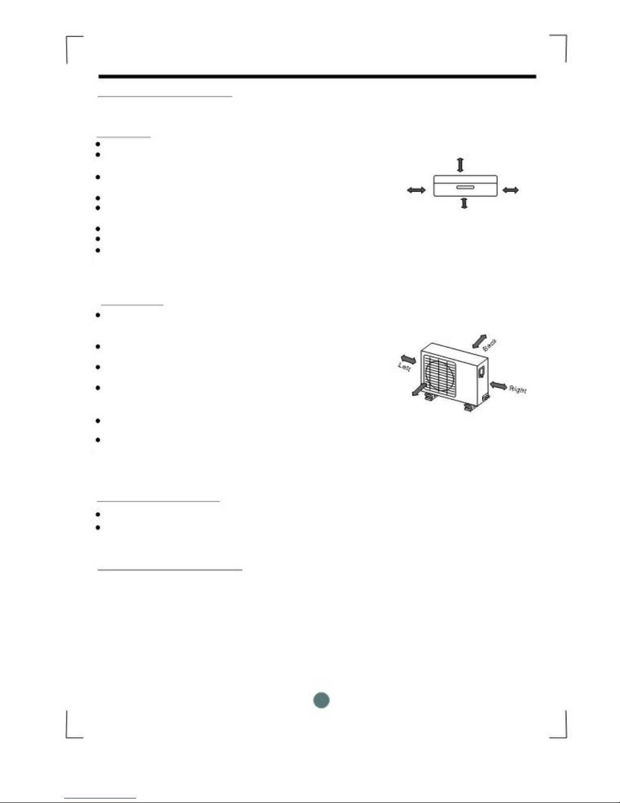
Indoor unit
Do not expose the indoor unit to heat or steam.
Select a place where there are no obstacles in front of
or around the unit.
Make sure that condensation drainage tube can be
conveniently routed away.
Do not install near a doorway.
Ensure the spaces indicated by arrows from the
wall, ceiling or other obstacles.
A place where noise prevention is taken into consideration.
Min. 3 ft. from TV or electronic instrument.
There should not be any direct sunlight on the indoor unit,
sunlight may fade the color of the unit.
More than 15cm
(to the ceiling)
More than More than
12cm 12cm
More than 2.0m
(from the floor)
Fig.1
Outdoor unit
If an awning is built over the outdoor unit it must be done in a
way that does not block air flow to the unit.
Keep the spaces indicated by arrows from wall or
other obstacles.
Do not place animals and plants in the path of the
air inlet or outlet.
Take the air conditioner weight into account and
select a place where noise, vibration, and hot air
discharged will not be an issue.
Do not install in a location exposed to flammable gas.
Do not install high frequency machines such as a
welding machine near the air conditioner.
Rooftop installation:
More than 30cm
More than 30cm
More than 60cm
Front
More than 200cm
Fig.2
If the outdoor unit is installed on a roof structure, be sure to level the unit.
Ensure the roof structure and anchoring method are adequate for the unit location.
Consult local codes regarding rooftop mounting.
Recommended Tools For Installation:
Level gauge
Screwdriver
Electric Drill
Hole Saw Bit
Flaring Tool
Torque Wrench
Adjustable Wrench
Tape Measure
Hex Wrench 4mm
Leak Detector
Vacuum pump
Gauge manifold
Users manual
Thermometer
Multi-meter
Pipe Cutter
3
INSTALLATION INSTRUCTIONS
Accessories
Number
Name of Accessories
Q¯ty
1
Installation Plate
1
2
Plastic Expansion Sheath
5-8 (depending on models)
3
Self-tapping Screw A ST3.9X25
5-8 (depending on models)
4
Seal
1
5
Drain
1
14
6
Connecting Liquid side
Pipe Assembly 38
12
Gas side
58
Parts you must purchase. Consult
the technician for the proper
pipe size.
7
Remote controller
1
8
Self-tapping Screw B ST2.9X10
Optional
2
9
Remote controller holder
parts
1
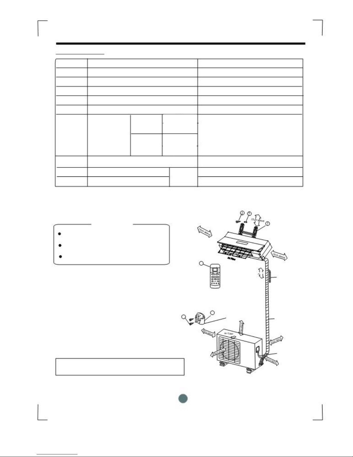
CAUTION
Use a stud finder to locate studs to prevent
unnecessary damage to the wall.
A minimum pipe run of 3 meters is required
to minimize vibration & excessive noise.
Two of the A, B and C directions should be
Self-tapping
screw A
free from obstructions (see fig. 3).
8
Remote Controller
7
>2.0m
Additional drain pipe
Self-tapping screw B
9 Remote controller
holder
Wrapping tape
A
Loop the
B cable.connective
This illustration is for explanation purposes only.
C
Copper lines must be insulated independently.
Fig.3
4
¼”
½”
INSTALLATION INSTRUCTIONS
Indoor unit installation
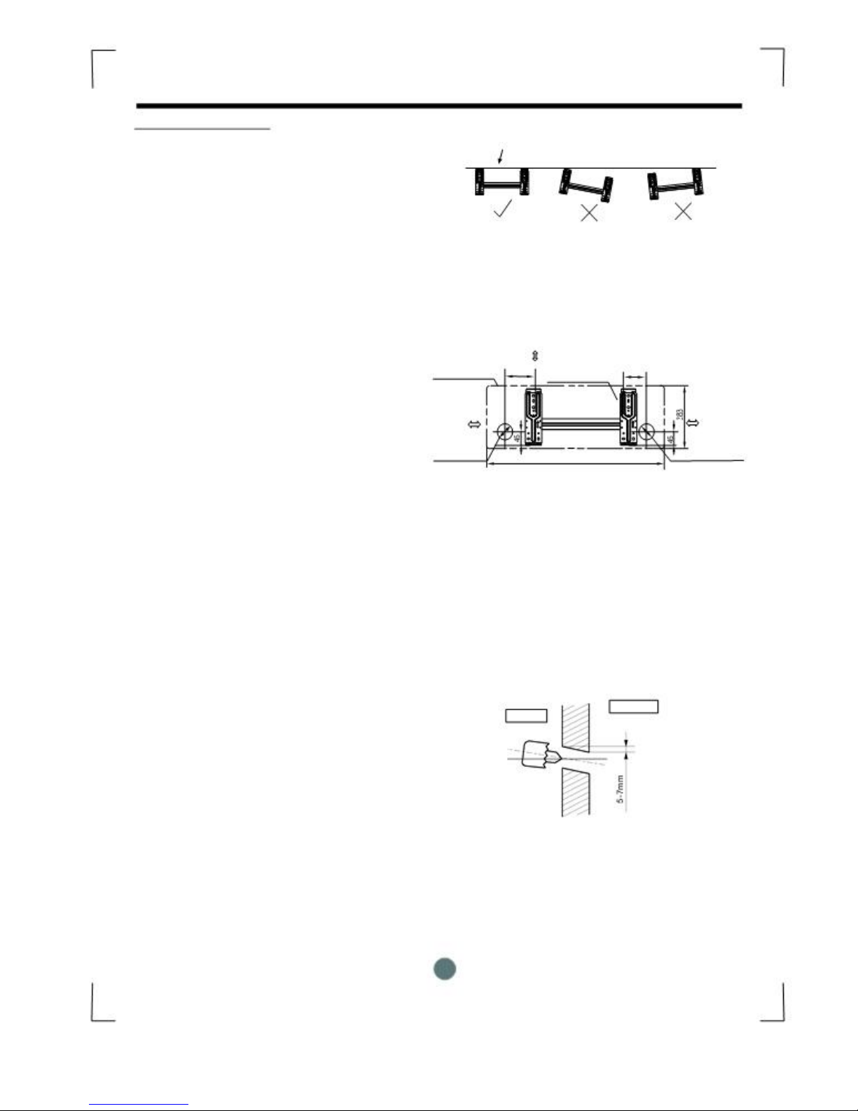
1. Fit the installation plate horizontally
on structural parts of the wall with
spaces around the installation plate.
2. If the wall is made of brick, concrete,
or the like, use #8 anchor screws of
the appropriate size.
3. Fit the installation plate on the wall
with eight (8) anchor screws.
Note:
Fit the installation plate and drill
holes in the wall according to the
wall structure and corresponding
mounting points on the installation
plate. The installation plate is different
according to the models.
(Dimensions are in "mm" unless
otherwise stated)
Drill a hole in the wall
1. Determine hole positions according
to the diagram detailed in Fig.5. Drill
one (1) hole (2 ½”) slanting slightly
to outdoor side.
2. Always use wall hole conduit when
drilling metal grid, metal plate, or the like.
Correct orientation
of Installation Plate
Fig.4
150mm or more to ceiling
Indoor unit outline 150 90
Installation plate
120mm or 120mm or
more to wall more to wall
Left rear side Right rear side
refrigerant refrigerant
pipe hole Õ65 900 pipe hole Õ
Fig.5
Wall
Outdoor
Indoor
Fig.6
5
INSTALLATION INSTRUCTIONS
Connective Tube and Drainage
Installation
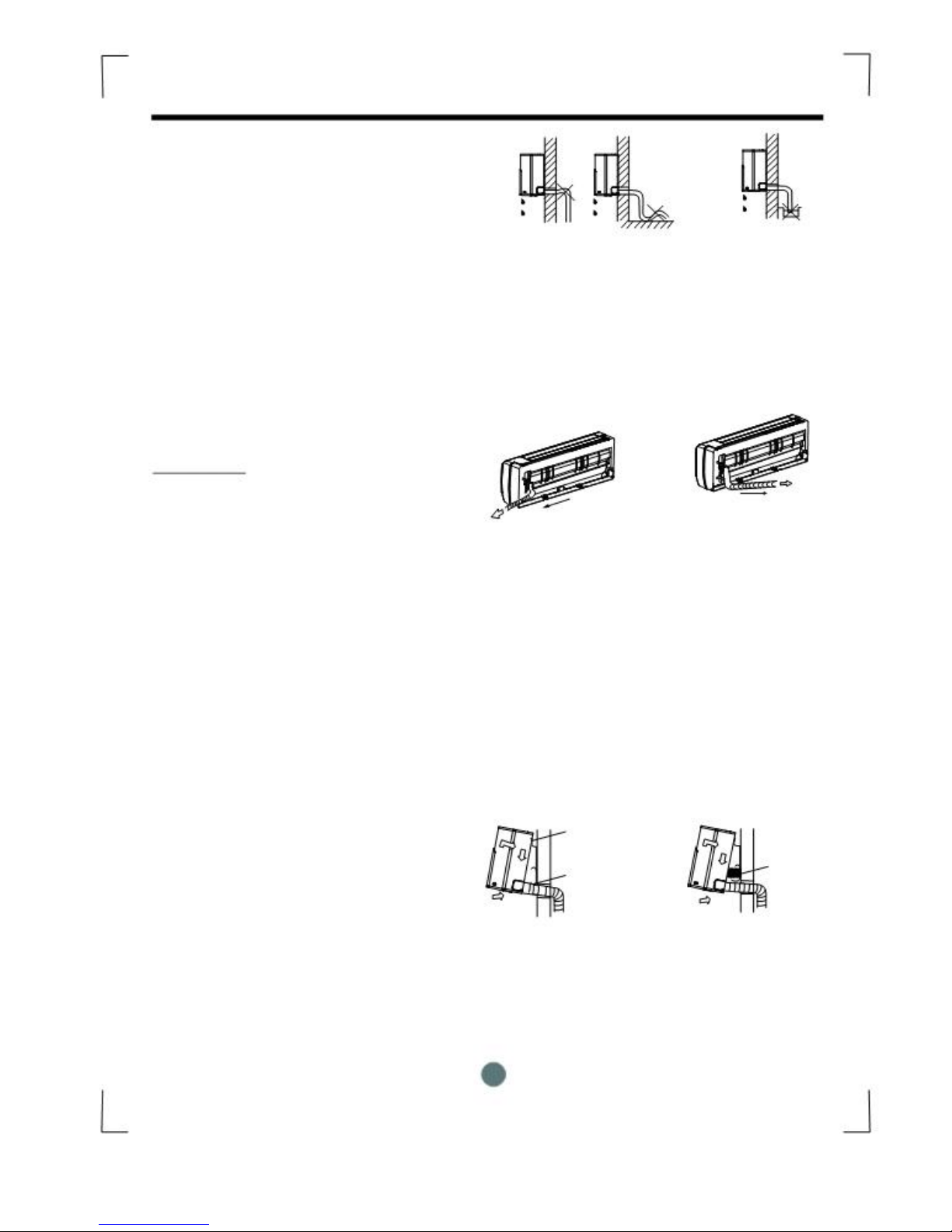
1. Run the drain hose sloping downward.
Do not install the drain hose as
illustrated in Fig.7.
2. When connecting extension drain hose,
insulate the connecting part of extension
drain hose with a shield pipe, do not let
the drain hose slack.
Refrigerant Tube Installation
IMPORTANT:
The unit can only use right-hand piping
or right rear piping as shown in
Fig.8.
1. Remove the cover for right-hand piping first.
2. For the right rear piping, install the piping as
shown in fig. 8
3. Fix the end of the connective pipe. (Refer
to Tightening Connection in
REFRIGERANT PIPING CONNECTION)
Indoor unit installation
1. Pass the piping through the hole in the
wall.
2. Put the upper claw at the back of the
indoor unit on the upper hook of the
installation plate, move the indoor unit
from side to side to see that it is securely
hooked (see Fig.9 & Fig.10).
3. Piping can easily be made by lifting the
indoor unit with a cushioning material
between the indoor unit and the wall.
Remove material after it is not needed.
4. Push the lower part of the indoor unit up
on the wall, then move the indoor unit
from side to side, up and down to check
if it is hooked securely.
Do not block water flow by a rise.
Right-hand piping
Fig.8
Upper Hook
Lower Hook
Fig.9
6
Do not put the end of
drain hose into water.
Fig.7
Right rear piping
Cushioning
material
Fig.10
INSTALLATION INSTRUCTIONS
Piping and wrapping
Bundle the tubing, connecting cable, and drain
hose with tape securely, evenly as shown in
Fig.11
Because the condensed water from rear of the
indoor unit is collected in the drain pan to be
piped out of room, do not put anything else in
the drain pan.
CAUTION
Connect the indoor unit first, then the
outdoor unit.
Do not allow the piping to drain out from the
back of the indoor unit.
Be careful not to let the drain hose slack.
Make sure to insulate the tubing.
Be sure that the drain hose is located at
the lowest side of the bundle. Locating at
the upper side can cause drain pan to
overflow inside the unit.
Never wrap the power wire along with control
cable.
Run the drain hose sloped downward to
drain out the condensed water smoothly.
Outdoor Unit Installation
Install the outdoor unit on a rigid base to
prevent increasing noise level and vibration.
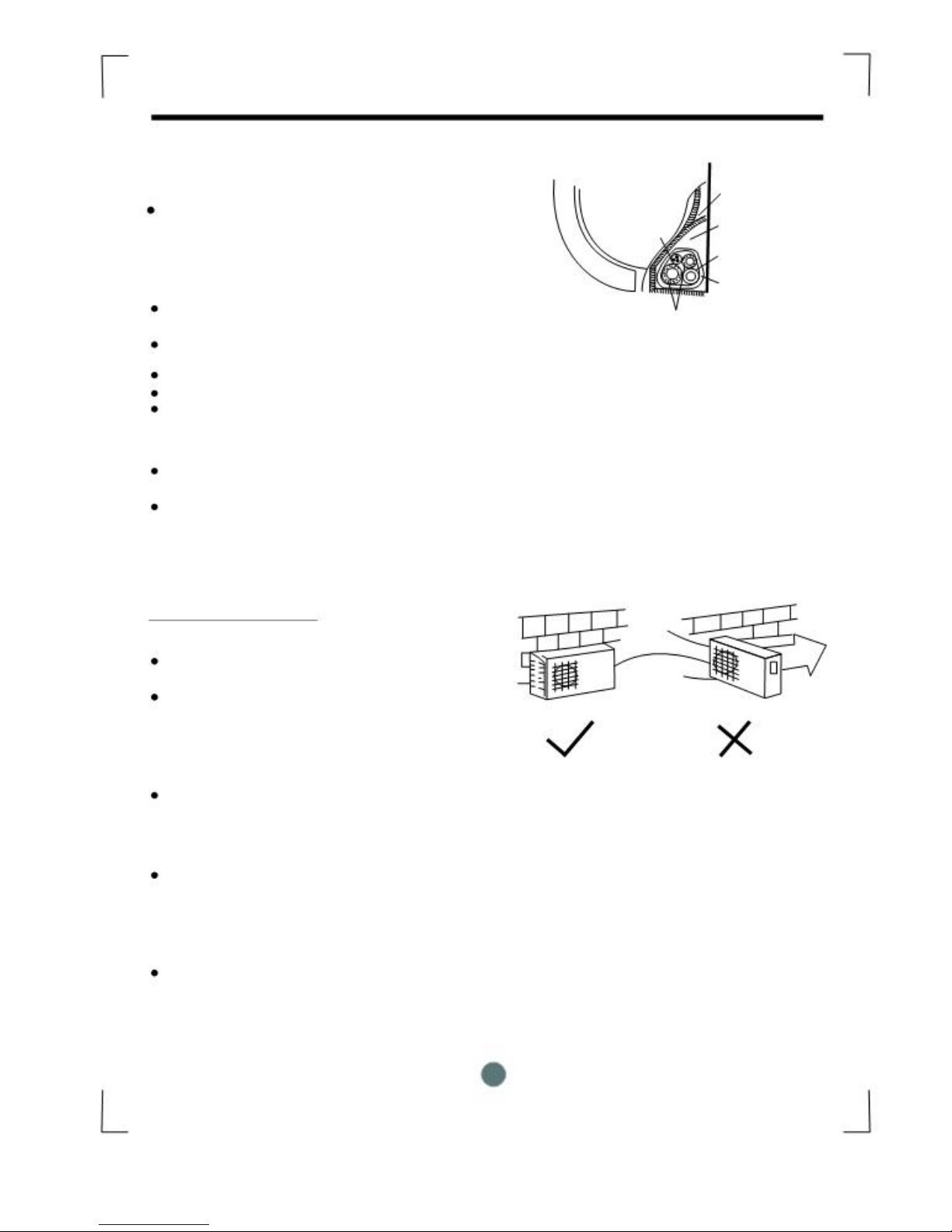
Determine the air outlet direction where the
discharged air is not blocked. In the case that
the installation site is exposed to strong wind,
make sure the fan is operating properly by
putting the unit lengthwise along the
wall or using a dust or shield plates.
Especially in windy area, install the unit to prevent the admission of wind. If using a suspending
installation, the installation bracket should
Follow the technique required in the
installation bracket diagram.
The installation wall should be solid brick,
concrete or the same intensity construction, or
actions to reinforce, damping supporting should
be taken. The connection between bracket and
wall, bracket and the air conditioner should be
firm, stable and reliable.
Be sure there are no obstacles which block air
flow.
Indoor unit Drain Pan
Connective Pipe room
cable
Drain hose
Wrapping belt
Connective pipe
Fig.11
Strong
wind
Fig.12
7
 Loading...