

Cornelius FCB Pinnacle 2 Flavor, FCB Pinnacle 4 Flavor Installation Manual

INSTALLATION MANUAL
FCB Pinnacle 2 and 4 Flavor
Release Date: November 17, 2005
Publication Number: 560007295INS
Revision Date: March 24, 2014
Revision: G
Visit the Cornelius web site at www.cornelius.com for all your Literature needs.

The products, technical information, and instructions contained in this manual are subject to change without notice.
These instructions are not intended to cover all details or variations of the equipment, nor to provide for every possi
ble contingency in the installation, operation or maintenance of this equipment. This manual assumes that the person(s) working on the equipment have been trained and are skilled in working with electrical, plumbing, pneumatic,
and mechanical equipment. It is assumed that appropriate safety precautions are taken and that all local safety and
construction requirements are being met, in addition to the information contained in this manual.
This Product is warranted only as provided in Cornelius’ Commercial Warrant applicable to this Product and is subject to all of the restrictions and limitations contained in the Commercial Warranty.
Cornelius will not be responsible for any repair, replacement or other service required by or loss or damage resulting
from any of the following occurrences, including but not limited to, (1) other than normal and proper use and normal
service conditions with respect to the Product, (2) improper voltage, (3) inadequate wiring, (4) abuse, (5) accident,
(6) alteration, (7) misuse, (8) neglect, (9) unauthorized repair or the failure to utilize suitably qualified and trained per
sons to perform service and/or repair of the Product, (10) improper cleaning, (11) failure to follow installation, operating, cleaning or maintenance instructions, (12) use of “non-authorized” parts (i.e., parts that are not 100%
compatible with the Product) which use voids the entire warranty, (13) Product parts in contact with water or the
product dispensed which are adversely impacted by changes in liquid scale or chemical composition.
Contact Information:
To inquire about current revisions of this and other documentation or for assistance with any Cornelius product contact:
www.cornelius-usa.com
800-238-3600
-
-
Trademarks and Copyrights:
This document contains proprietary information and it may not be reproduced in any way without permission from
Cornelius.
This document contains the original instructions for the unit described.
CORNELIUS INC
101 Regency Drive
Glendale Heights, IL
Tel: + 1 800-238-3600
Printed in U.S.A.

FCB Pinnacle 2 and 4 Flavor Installation Manual
!
WARNING:
!
WARNING:
!
WARNING:
CAUTION:
!
SAFETY INSTRUCTIONS
SAFETY
Before starting installation, read and understand all safety label and warnings on the machine. Also review and
understand all safety instructions in the owners, installation and service manuals.
Failure to comply could result in serious injury, death or damage to the equipment.
QUALIFIED SERVICE PERSONNEL
Only trained and certified electrical, plumbing and refrigeration technicians should service this unit.
All wiring and plumbing must conform to national and local codes. Failure to comply could
result in serious injury, death or equipment damage.
SAFETY PRECAUTIONS
This unit has been specifically designed to provide protection against personal injury. To ensure continued
protection observe the following:
Disconnect power to the unit before servicing. Follow all lock out/tag out procedures established by the user. Verify all
power is off to the unit before performing any work.
Failure to comply could result in serious injury, death or damage to the equipment.
Always be sure to keep area around the unit clean and free of clutter.
Failure to keep this area clean may result in injury or equipment damage.
© 2003-2014, Cornelius Inc. - 1 - Publication Number: 560007295INS
FCB Pinnacle 2 and 4 Flavor Installation Manual
!
DANGER:
!
WARNING:
CAUTION:
!
INSTALLATION INSTRUCTIONS
INSTALLATION REQUIREMENTS
Requirements Summary
Environment Indoor installation only
Temperature 40 to 90°F ambient temperature
2 60 psi minimum at unit
CO
Syrup 60 psi minimum at pressure switch,.35 ounces per sec. (.17 gpm) at unit
Water 25 psi minimum (flowing), 3.5 ounces per sec./100 gallon per hour minimum (per 2
barrels). Minimum 1/2” ID water inlet recommended
Electrical 60 Hz Unit 208-230 volts, 20 amp, 60 Hz (2 Flavor)
208-230 volts, 40 amp, 60 Hz (4 Flavor)
50 Hz Unit 230 volts, 15 amp, 50 Hz (2 Flavor)
Electrical Requirements
Refer to the nameplate to determine the power requirements before connecting electrical power to the unit. All of
the power cords shall comply with safety requirements outlined in the EC Standards (EN60335-1 1 Clause 24.1) in
countries where CE compliance is required. All cords must be HD 21 or HD 22.
Voltage across contactor terminals L1 and L2, with compressor running, must be within voltage limits described in
the Requirement Summary.
To avoid possible serious injury or death the ELCB (earth leakage circuit breaker) must be installed in the electrical
circuit of all units.
To avoid possible electrical shock make sure the unit is properly grounded by connecting the earth ground cable, in
the power cord, to any connection in the machine marked with a ground symbol.
The wiring must be properly grounded and connected through a disconnect switch (slow–blow fuse or equivalent
HVAC/R circuit breaker - 20 amp for the 2 Flavor model and 40 amp for the 4 Flavor model) for 60Hz units. Refer to
the local and national wiring codes for the 50Hz unit. All wiring must conform to national and local codes.
Line Voltage
The recommended line voltages for the Pinnacle unit are as follows:
The unit has a low voltage cut out at 180 VAC and a high voltage cut out at 260 VAC.
Voltage Corrective Action
Below 180 V DO NOT connect unit.
180 to 190 VAC Boost voltage by +32 V.
191 to 208 VAC Boost voltage by +16 V.
209 to 240 VAC Use line voltage.
241 to 253 VAC Reduce voltage by -16 V.
254 to 272 VAC Reduce voltage by -32 V.
Above 272 VAC DO NOT connect unit.
Publication Number: 560007295INS - 2 - © 2003-2014, Cornelius Inc.
FCB Pinnacle 2 and 4 Flavor Installation Manual
CAUTION:
!
CAUTION:
!
CAUTION:
!
RemoveBolts
Environmental Requirements
Ambient (room) temperature must not exceed 90 F. Temperatures in excess of 90 F will void the factory warranty
and may eventually result in refrigeration system failure. If the unit is powered up while it is over 120 F, the unit will
not function. Call Service.
If the inside cabinet temperature is over 120F, let the temperature cool to 100F before continuing the install.
There must be proper clearance on all sides and on top of the unit to avoid overheating and damaging the unit and
voiding the warranty.
This unit is designed for indoor installation only (in a non-harsh environment). See the Requirements Summary for
this information.
The water in the unit will freeze and may damage the unit if the unit is exposed to freezing temperature.
DELIVERY INSPECTION AND UNPACKING
Inspection
Inspect the unit for damage or irregularities upon delivery. Immediately report problems to the delivering carrier and
file a claim with that carrier.
Unpacking
1. Remove 4 bolts and strapping from the crate. Remove staples and lift the carton off of the pallet.
2. Remove packing fillers from top of the unit.
3. Open the packages of loose parts and inspect all of the parts. The Magnet Puller Tool is P/N 560003662
(stored at the inside base of the frame).
© 2003-2014, Cornelius Inc. - 3 - Publication Number: 560007295INS
Figure 1.
FCB Pinnacle 2 and 4 Flavor Installation Manual
2.IntotheBottomof
thePowerBox
1.Throughthe
FrameStrainRelief
INITIAL INSTALLATION PROCEDURE
NOTE: Tubing, hoses, and cabling come from beneath or in back of the unit. Make a hole in the
counter or wall to accommodate them or allow for no less then 4 inches of clearance behind the
unit and 18 inches above the unit. Ten inches of clearance, behind the unit, is required for filter
removal.
Connect Electrical Power - 50Hz and 60Hz Power
NOTE: Refer to the nameplate for power requirements before connecting electrical power to the
unit.
1. Switch the power to the unit off or remove the fuse to the electrical power circuit breaker.
2. Remove side panel.
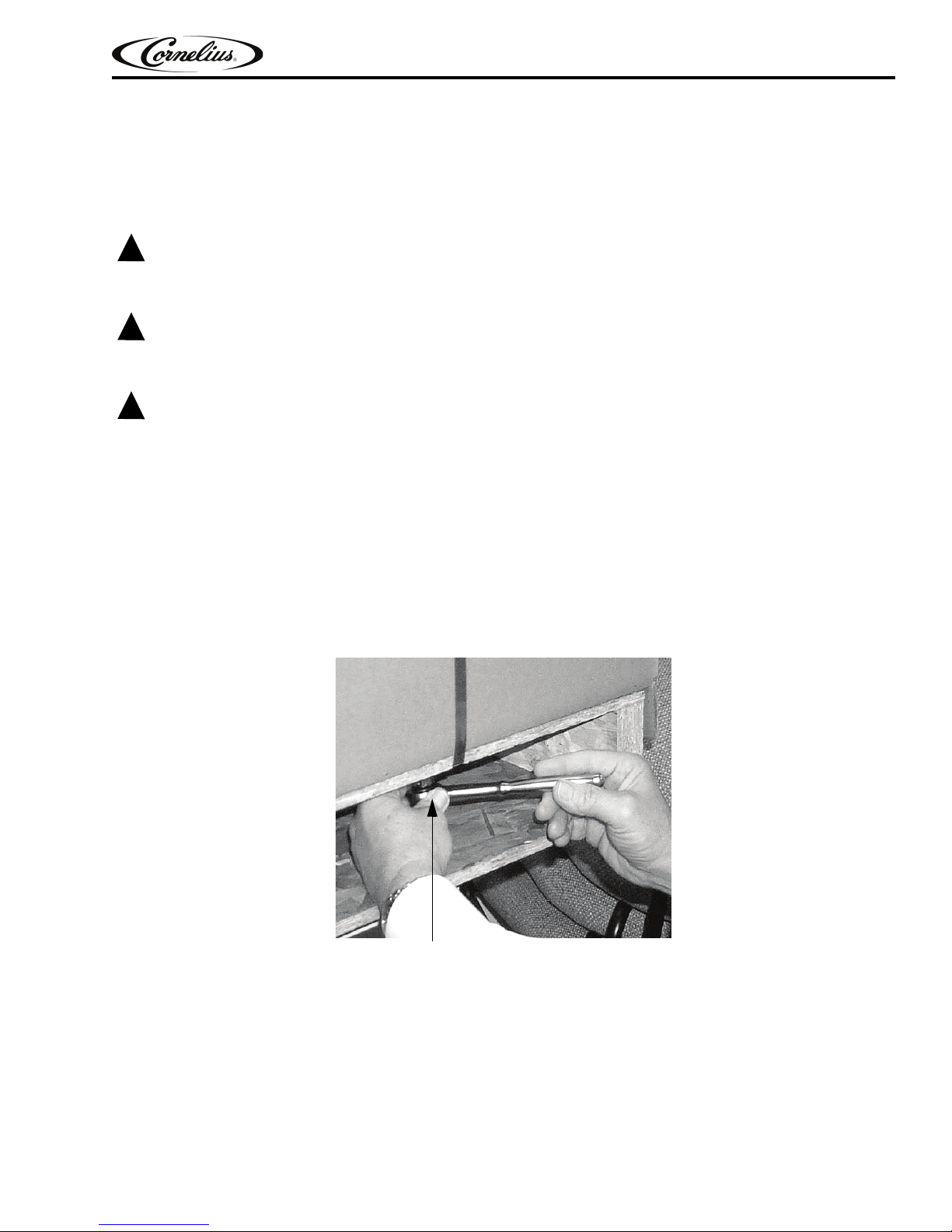
3. Feed the power cord through the strain relief either through the bottom or back of the frame, see Figure 2.
and into the power box.
Publication Number: 560007295INS - 4 - © 2003-2014, Cornelius Inc.
Figure 2.
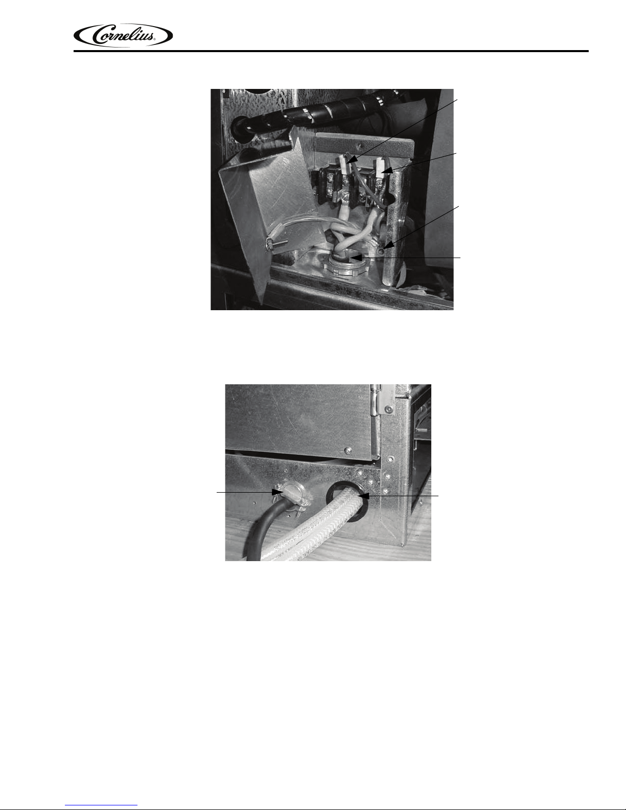
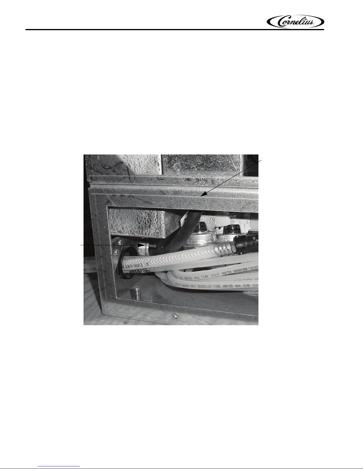
4. Connect the power cord to the terminal block (Figure 3.)
PowerIN
BlacktoBrown
WhitetoBlue
GroundLug
PowerCord
StrainRelief
ProductInlet
Figure 3.
5. Connect the ground wire to the ground lug (Figure 3.)
FCB Pinnacle 2 and 4 Flavor Installation Manual
6. Pull the slack out of cable and tighten the 2 strain relieves (see Figure 4.) Replace the power box cover. DO
NOT turn on the power at this time.
Figure 4.
Testing Power
1. Turn on power to the unit. Watch for the “Initializing - Please Standby” message, displayed for 3-5 seconds,
and the merchandiser to light up.
2. Check to make sure the error messages appear.
3. Verify that the Syrup 1 and 2, CO
2, and Water Sold Out errors exist. Press ERR to see the complete list of
errors.
4. If these errors DO NOT appear, troubleshooting the Sold Out System is required. Continue if the errors are
present.
© 2003-2014, Cornelius Inc. - 5 - Publication Number: 560007295INS

FCB Pinnacle 2 and 4 Flavor Installation Manual
!
WARNING:
!
DANGER:
CO2 Installation
Secure the CO2 cylinder in an upright position with a safety chain to prevent it from falling over and avoid personal
injury and property damage.
CO2 displaces oxygen. Strict attention MUST be observed in the prevention of CO2 gas leaks in the entire CO2 and
soft drink system. If a CO
contaminated area before attempting to repair the leak. Personnel exposed to high concentrations of CO
experience tremors which are followed rapidly by loss of consciousness and DEATH.
2 gas leak is suspected, particularly in a small area, IMMEDIATELY ventilate the
2 gas
NOTE: There are 2 CO
System. High pressure Cylinder requires a Primary Regulator with a minimum inlet pressure of 500
psi. Low Pressure Bulk System requires a Secondary Regulator with a Maximum inlet pressure of
200 psi.
1. As stated in the Warning, secure the CO
2. Unscrew the protector cap from the CO
any dirt or dust from outlet fitting before installing the primary CO
3. Remove the shipping plug from the primary CO
ket is in place inside the nut. Install the regulator assembly on the CO
read, then tighten the coupling.
4. Connect the lines to the CO
2 delivery systems available: High Pressure Cylinder; Low Pressure Bulk
2 cylinder with a chain so it can not fall over.
2 cylinder valve. Open the CO2 cylinder valve momentarily to blow
2 regulator, then close the valve.
2 regulator assembly coupling nut and make sure the gas-
2 cylinder so the gages can be easily
2 manifold.
Connect Syrup and Water Lines
Note the points given below before proceeding:
1. Syrup and CO2 connections require 3/8” I.D. tubing. Water connections require 1/2” I.D. tubing.
2. All hoses must reach the back of the unit plus an adequate amount of extra tubing to allow the unit to be
pulled out for servicing.
3. Size, install, and maintain the water pipe, connections, and fixtures directly connected to a potable water
supply in accordance with Federal, State, and Local codes.
4. It is the installer’s responsibility to ensure that the potable water supply is equipped with protection against
backflow. This protection can be an air gap as defined by ANSI/ASME A112.1.2-1979 or by an approved
vacuum breaker or other approved method.
5. If the flowing water pressure at the back of the unit is less than the specified 25 psi and 100 GPH flowrate
(per 2 barrels) a water pressure booster is required.
6. It is recommended that a water shutoff valve and water filter be installed in the water supply line.
Use the appropriate fittings and clamps to connect the CO2, Syrup, and Water lines to the unit. Do Not turn on the
water or syrup sources at this time.
Pressurizing CO2 System
1. Open the CO2 cylinder valve slightly to allow lines to slowly fill with gas. When lines are fully pressurized,
open the CO
2. Adjust the CO
at this time.
3. Adjust the Blendonator tank secondary CO
22 – 28 psi (the regulator is factory set to 23 psi). Open the Freeze Cylinder Shutoff Valves (see Figure 5.),
valve lever parallel to valve body (open position). The CO
Publication Number: 560007295INS - 6 - © 2003-2014, Cornelius Inc.
2 cylinder valve all the way until it back-seats itself (this prevents leaks from the valve).
2 cylinder regulator for the unit to 60 psi at the unit. Do Not turn on the syrup CO2 regulator
2 regulators (see Figure 5.), located inside the unit, to between
2error on the display will automatically reset itself.
 Loading...