

Cornelius FCB OVERCOUNTER POST-MIX DISPENSER Service Manual
FCB OVERCOUNTER
POST-MIX DISPENSER
Service Manual
IMPORTANT:
TO THE INSTALLER.
It is the responsibility of the Installer to
ensure that the water supply to the
dispensing equipment is provided with
protection against backflow by an air gap
as defined in ANSI/ASME A112. 1.2-1979; or
an approved vacuum breaker or other such
method as proved effective by test.
Water pipe connections and fixtures
directly connected to a potable water
supply shall be sized, installed, and
maintained according to federal, state, and
local laws.
WITH V3+FEATURES
Part No. 2992
May 31, 1994
Revised: April 4, 1995
THIS DOCUMENT CONTAINS IMPORTANT INFORMATION
This Manual must be read and understood before installing or operating this equipment
IMI CORNELIUS INC; 1994–95
PRINTED IN U.S.A
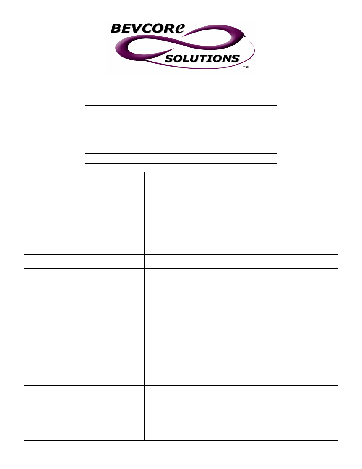
Part # Corrections/Update Document
Unit Type/Model # Manual #
FCB OC2 POST MIX
DISPENSER W/V3+
Unit Part Numbers:
416136xxx
496136xxx
Page Item Old Part Desc. New Part Desc. Agent Date Notes
71 53 2467 FOAM PACK 4467 FOAM PACK JLS 01/24/03
72 66 326000000 COMPRESSOR
KIT 2HP 230V/60
72 66 324233000 COMPRESSOR
KIT 2HP 230/50
72 78 324120000 GEAR MOTOR
1/4HP 220V
72 78 2472 GEAR MOTOR
1/4HP 220/240V
50H KLAUBER
72 78 3471 GEAR MOTOR
1/8HP 208/240
50/60H
EMERSON
72 78 2108 MOTOR 1/4HP
220/240 50H
FASCO
74 3 183412000 REGULATOR
ASSY 100PSI
80 4 324047000 BLENDER TANK 324194888
87 n/a 3232 DRIVE SHAFT JLS 01/24/03
560004343 COMPRESSOR
KIT 60H
DOMESTIC
560004342 COMPRESSOR
KIT 50H
EXPORT
324120088 GEAR MOTOR
1/4HP 240V/60
4210 GEAR MOTOR
KIT 230/50/60
EMERSON
4689 GEAR MOTOR
230/50/60
EMERSON
N/A JLS 01/24/03 Obsolete
183412016 REGULATOR
SECONDARY
100PSI
BLENDER TANK
324205888
FOR SINGLE
FLOAT USE
OR
BLENDER TANK
FOR DOUBLE
FLOAT USE
2992
JLS 01/24/03 Includes all
components and
instructions to
convert from R502
to R404.
JLS 01/24/03 Includes all
components and
instructions to
convert from R502
to R404.
JLS 01/24/03 Klauber motor – for
OC1 only
JLS 01/24/03 Includes
components and
instructions to
replace Klauber
with Emerson
motor
JLS 01/24/03 Use Emerson motor
4689 when
replacing an
existing Emerson
motor
JLS 01/24/03
JLS 01/24/03

PIN

TABLE OF CONTENTS
GENERAL DESCRIPTION 1. . . . . . . . . . . . . . . . . . . . . . . . . . . . . . . . . . . . . . . . . . . . . . . . . .
GENERAL DESCRIPTION 1. . . . . . . . . . . . . . . . . . . . . . . . . . . . . . . . . . . . . . . . . . . . . .
UNIT DESCRIPTION 1. . . . . . . . . . . . . . . . . . . . . . . . . . . . . . . . . . . . . . . . . . . . . . . . . . .
THEORY OF OPERATION 2. . . . . . . . . . . . . . . . . . . . . . . . . . . . . . . . . . . . . . . . . . . . . .
DEFROST SYSTEMS 3. . . . . . . . . . . . . . . . . . . . . . . . . . . . . . . . . . . . . . . . . . . . . . . . . .
MANUAL DEFROST SYSTEM 3. . . . . . . . . . . . . . . . . . . . . . . . . . . . . . . . . . . . . .
AUTOMATIC DEFROST SYSTEM 3. . . . . . . . . . . . . . . . . . . . . . . . . . . . . . . . . . .
‘‘SLEEP’’ (SLEEP TIME) 4. . . . . . . . . . . . . . . . . . . . . . . . . . . . . . . . . . . . . . . . . . . . . . . .
‘‘WAKE UP’’ (WAKE UP TIME) 4. . . . . . . . . . . . . . . . . . . . . . . . . . . . . . . . . . . . . . . . . . .
INSTALLATION 7. . . . . . . . . . . . . . . . . . . . . . . . . . . . . . . . . . . . . . . . . . . . . . . . . . . . . . . . . . . .
UNPACKING AND INSPECTION 7. . . . . . . . . . . . . . . . . . . . . . . . . . . . . . . . . . . . . . . .
IDENTIFICATION OF LOOSE-SHIPPED PARTS 7. . . . . . . . . . . . . . . . . . . . . . . . . . .
ELECTRICAL POWER REQUIREMENTS 8. . . . . . . . . . . . . . . . . . . . . . . . . . . . . . . . .
50 HZ UNIT 8. . . . . . . . . . . . . . . . . . . . . . . . . . . . . . . . . . . . . . . . . . . . . . . . . . . . . . .
60 HZ UNIT 8. . . . . . . . . . . . . . . . . . . . . . . . . . . . . . . . . . . . . . . . . . . . . . . . . . . . . . .
SELECTING LOCATION 8. . . . . . . . . . . . . . . . . . . . . . . . . . . . . . . . . . . . . . . . . . . . . . . .
INSTALLING UNIT 9. . . . . . . . . . . . . . . . . . . . . . . . . . . . . . . . . . . . . . . . . . . . . . . . . . . . .
INSTALLING LEVELING LEGS 9. . . . . . . . . . . . . . . . . . . . . . . . . . . . . . . . . . . . . .
INSTALLING DRIP TRAY SUPPORTS 9. . . . . . . . . . . . . . . . . . . . . . . . . . . . . . .
INSTALLING DRIP TRAY DRAIN HOSE KIT 9. . . . . . . . . . . . . . . . . . . . . . . . . .
PREPARING UNIT FOR CONNECTION TO SYRUP, CO2, AND CITY
PLAIN WATER SOURCES 9. . . . . . . . . . . . . . . . . . . . . . . . . . . . . . . . . . . . . . . . . .
INSTALLING PRIMARY CO2 REGULATOR ASSEMBLY ON CO2
CYLINDER 9. . . . . . . . . . . . . . . . . . . . . . . . . . . . . . . . . . . . . . . . . . . . . . . . . . . . . . .
CONNECTING SOFT DRINK TANKS CO2 LINES TO PRIMARY CO2
REGULATOR ASSEMBLY 11. . . . . . . . . . . . . . . . . . . . . . . . . . . . . . . . . . . . . . . . . .
PREPARING UNIT SYRUP INLET LINES FOR CONNECTION TO SOFT
DRINK TANKS 12. . . . . . . . . . . . . . . . . . . . . . . . . . . . . . . . . . . . . . . . . . . . . . . . . . . .
CONNECTING CO2 SOURCE LINE TO UNIT CO2 INLET LINE 12. . . . . . . . .
CONNECTING CITY PLAIN WATER SOURCE LINE TO UNIT 12. . . . . . . . . .
CONNECTING ELECTRICAL POWER CIRCUIT TO THE UNIT 12. . . . . . . . .
PREPARATION FOR OPERATION 13. . . . . . . . . . . . . . . . . . . . . . . . . . . . . . . . . . . . . . .
TURNING ON ELECTRICAL POWER TO UNIT 13. . . . . . . . . . . . . . . . . . . . . . .
TURNING ON CO2 SUPPLY TO THE UNIT 13. . . . . . . . . . . . . . . . . . . . . . . . . . .
ADJUSTING PRIMARY CO2 REGULATOR 13. . . . . . . . . . . . . . . . . . . . . . . . . . .
ADJUSTING PRODUCT BLENDER TANKS SECONDARY CO2 13. . . . . . . . .
ADJUSTING CARBONATOR SECONDARY CO2 REGULATOR 13. . . . . . . . .
STARTING FCB AND ADJUSTING WATER-TO-SYRUP “RATIO” (BRIX) OF
DISPENSED PRODUCT 14. . . . . . . . . . . . . . . . . . . . . . . . . . . . . . . . . . . . . . . . . . .
FILLING FREEZE CYLINDERS WITH PRODUCT 15. . . . . . . . . . . . . . . . . . . . .
CHECKING UNIT FOR SYRUP, CO2, OR PLAIN WATER LEAKS 15. . . . . . .
PLACING UNIT IN OPERATING LOCATION 16. . . . . . . . . . . . . . . . . . . . . . . . . .
ADJUSTING BEATER MOTOR CURRENT (EITHER SIDE) 16. . . . . . . . . . . . .
Page
i
2992

TABLE OF CONTENTS (cont’d)
ADJUSTMENT AND PROGRAMMING MAIN MENU SELECTIONS, COMPONENTS
“DIAGNOSE’’ (DIAGNOSTIC MODE), AND (‘‘TOTALS” DISPLAYED CYCLES
AND HOURS TOTALS) INTO UNIT 17. . . . . . . . . . . . . . . . . . . . . . . . . . . . . . . . . . . . . .
PROGRAMMING MAIN MENU SELECTION ONTO MESSAGE DISPLAY 17
SETTING CLOCK (TIME OF DAY) 17. . . . . . . . . . . . . . . . . . . . . . . . . . . . . . . . . . .
PROGRAMMING ‘‘DEFROST’’ (AUTOMATIC) SETTINGS INTO UNIT 18. . .
PROGRAMMING ‘‘SLEEP’’ (SLEEP TIME) INTO UNIT 19. . . . . . . . . . . . . . . . .
PROGRAMMING ‘‘WAKE UP’’ (WAKE UP TIME) INTO UNIT 19. . . . . . . . . . . .
PROGRAMMING POINT OF SALE MESSAGE DISPLAY 22. . . . . . . . . . . . . . .
ADJUSTING “VIS SET” (PRODUCT VISCOSITY) OF DISPENSED
PRODUCT 22. . . . . . . . . . . . . . . . . . . . . . . . . . . . . . . . . . . . . . . . . . . . . . . . . . . . . . . .
‘‘VIS READ’’ (ACTUAL VISCOSITY READOUT) OF PRODUCT IN
FREEZE CYLINDERS 22. . . . . . . . . . . . . . . . . . . . . . . . . . . . . . . . . . . . . . . . . . . . . .
DISPLAYED EVAPORATOR REFRIGERATION COILS INLETS AND
COMMON OUTLET SENSORS TEMPERATURES. 22. . . . . . . . . . . . . . . . . . . .
‘‘VOLTAGE’’ (DISPLAYED VOLTAGE READOUT) 23. . . . . . . . . . . . . . . . . . . . . .
PROGRAMMING COMPONENTS ‘‘DIAGNOSE’’ (DIAGNOSTIC MODE)
INTO UNIT 23. . . . . . . . . . . . . . . . . . . . . . . . . . . . . . . . . . . . . . . . . . . . . . . . . . . . . . .
DISPLAYING ‘‘TOTALS’’ (DISPLAYED CYCLES AND HOURS TOTALS)
ONTO MESSAGE DISPLAY 26. . . . . . . . . . . . . . . . . . . . . . . . . . . . . . . . . . . . . . . .
PROGRAMMING FREEZE CYLINDERS BEATER “MOTORS” INTO
UNIT ELECTRONICS 26. . . . . . . . . . . . . . . . . . . . . . . . . . . . . . . . . . . . . . . . . . . . . .
PROGRAMMING PROPER REFRIGERANT TYPE INTO UNIT
ELECTRONICS 27. . . . . . . . . . . . . . . . . . . . . . . . . . . . . . . . . . . . . . . . . . . . . . . . . . .
DISPLAYED ERROR CONDITIONS 27. . . . . . . . . . . . . . . . . . . . . . . . . . . . . . . . .
OPERATOR’S INSTRUCTIONS 29. . . . . . . . . . . . . . . . . . . . . . . . . . . . . . . . . . . . . . . . . . . . .
Page
CONTROL PANEL ASS’Y SWITCHES AND DISPLAYED MESSAGES 29. . . . . . .
CONTROL PANEL ASS’Y SWITCHES 29. . . . . . . . . . . . . . . . . . . . . . . . . . . . . . .
CONTROL PANEL ASSEMBLY DISPLAY MESSAGES 30. . . . . . . . . . . . . . . . .
FREEZE CYLINDERS MANUAL OR AUTOMATIC DEFROST SYSTEMS 31. . . . .
MANUAL DEFROST SYSTEM 31. . . . . . . . . . . . . . . . . . . . . . . . . . . . . . . . . . . . . .
AUTOMATIC DEFROST SYSTEM 31. . . . . . . . . . . . . . . . . . . . . . . . . . . . . . . . . . .
‘‘SLEEP’’ (SLEEP TIME) OPERATION 31. . . . . . . . . . . . . . . . . . . . . . . . . . . . . . . . . . . .
‘‘WAKE UP’’ (WAKE UP TIME) 32. . . . . . . . . . . . . . . . . . . . . . . . . . . . . . . . . . . . . . . . . . .
FACEPLATE RELIEF VALVES 32. . . . . . . . . . . . . . . . . . . . . . . . . . . . . . . . . . . . . . . . . . .
PRODUCT SAMPLE VALVES 32. . . . . . . . . . . . . . . . . . . . . . . . . . . . . . . . . . . . . . . . . . .
PRODUCT SHUTOFF VALVES 32. . . . . . . . . . . . . . . . . . . . . . . . . . . . . . . . . . . . . . . . . .
PRIMARY CO2 REGULATOR 32. . . . . . . . . . . . . . . . . . . . . . . . . . . . . . . . . . . . . . . . . . .
SECONDARY CO2 REGULATORS 32. . . . . . . . . . . . . . . . . . . . . . . . . . . . . . . . . . . . . .
CARBONATED WATER FLOW REGULATORS 32. . . . . . . . . . . . . . . . . . . . . . . . . . . .
SYRUP FLOW REGULATORS 32. . . . . . . . . . . . . . . . . . . . . . . . . . . . . . . . . . . . . . . . . .
DISPENSING VALVES 32. . . . . . . . . . . . . . . . . . . . . . . . . . . . . . . . . . . . . . . . . . . . . . . . .
DISPENSED PRODUCT CONDITIONS 33. . . . . . . . . . . . . . . . . . . . . . . . . . . . . . . . . . .
‘‘OVERRUN’’, AS APPLIED TO FROZEN CARBONATED BEVERAGES 33. .
OPERATING CHARACTERISTICS 34. . . . . . . . . . . . . . . . . . . . . . . . . . . . . . . . . . . . . . .
OPERATING UNIT 34. . . . . . . . . . . . . . . . . . . . . . . . . . . . . . . . . . . . . . . . . . . . . . . . . . . . .
2992
ii

TABLE OF CONTENTS (cont’d)
REPLENISHING SYRUP SUPPLY 34. . . . . . . . . . . . . . . . . . . . . . . . . . . . . . . . . . . . . . .
PRODUCT FLAVOR CHANGE 35. . . . . . . . . . . . . . . . . . . . . . . . . . . . . . . . . . . . . . . . . .
CHECKING CO2 SUPPLY 35. . . . . . . . . . . . . . . . . . . . . . . . . . . . . . . . . . . . . . . . . . . . . .
CLEANING AND SANITIZING 35. . . . . . . . . . . . . . . . . . . . . . . . . . . . . . . . . . . . . . . . . . .
DAILY CLEANING 35. . . . . . . . . . . . . . . . . . . . . . . . . . . . . . . . . . . . . . . . . . . . . . . . .
SANITIZING 35. . . . . . . . . . . . . . . . . . . . . . . . . . . . . . . . . . . . . . . . . . . . . . . . . . . . . .
CLEANING CONDENSER COIL 35. . . . . . . . . . . . . . . . . . . . . . . . . . . . . . . . . . . . . . . . .
LUBRICATION 35. . . . . . . . . . . . . . . . . . . . . . . . . . . . . . . . . . . . . . . . . . . . . . . . . . . . . . . .
ADJUSTMENTS 35. . . . . . . . . . . . . . . . . . . . . . . . . . . . . . . . . . . . . . . . . . . . . . . . . . . . . . .
CARBONATED WATER FLOW RATE 35. . . . . . . . . . . . . . . . . . . . . . . . . . . . . . . .
WATER-TO-SYRUP “RATIO” (BRIX) OF DISPENSED PRODUCT 36. . . . . . .
CO2 REGULATORS 36. . . . . . . . . . . . . . . . . . . . . . . . . . . . . . . . . . . . . . . . . . . . . . .
ADJUSTING BEATERS MOTORS CURRENTS 36. . . . . . . . . . . . . . . . . . . . . . .
PROGRAMMING MAIN MENU SELECTIONS ONTO MESSAGE DISPLAY 36
SETTING ‘‘CLOCK’’ (TIME OF DAY) 36. . . . . . . . . . . . . . . . . . . . . . . . . . . . . . . . .
PROGRAMMING ‘‘DEFROST’’ (AUTOMATIC) SETTINGS INTO UNIT 36. .
PROGRAMMING ‘‘SLEEP’’ (SLEEP TIME) INTO UNIT 36. . . . . . . . . . . . . . . . .
PROGRAMMING ‘‘WAKE UP’’ (WAKE UP) TIME INTO UNIT 37. . . . . . . . . . . .
PROGRAMMING POINT OF SALE MESSAGE DISPLAY 37. . . . . . . . . . . . . . .
ADJUSTING ‘‘VIS SET’’ (PRODUCT VISCOSITY) OF DISPENSED
PRODUCT 37. . . . . . . . . . . . . . . . . . . . . . . . . . . . . . . . . . . . . . . . . . . . . . . . . . . . . . . .
DISPLAYED EVAPORATOR REFRIGERATION COILS INLETS AND
COMMON OUTLET SENSORS TEMPERATURES 37. . . . . . . . . . . . . . . . . . . .
‘‘VOLTAGE’’ (DISPLAYED VOLTAGE READOUT) 37. . . . . . . . . . . . . . . . . . . . . .
PROGRAMMING COMPONENTS ‘‘DIAGNOSE’’ (DIAGNOSTIC MODE)
INTO UNIT 37. . . . . . . . . . . . . . . . . . . . . . . . . . . . . . . . . . . . . . . . . . . . . . . . . . . . . . .
DISPLAYING ‘‘TOTALS’’ (DISPLAYED CYCLES AND HOURS TOTALS)
ONTO MESSAGE DISPLAY 37. . . . . . . . . . . . . . . . . . . . . . . . . . . . . . . . . . . . . . . .
PROGRAMMING PROPER REFRIGERANT TYPE INTO UNIT
ELECTRONICS 37. . . . . . . . . . . . . . . . . . . . . . . . . . . . . . . . . . . . . . . . . . . . . . . . . . .
DISPLAYED ERROR CONDITIONS 37. . . . . . . . . . . . . . . . . . . . . . . . . . . . . . . . .
WATER STRAINER SCREEN AND DOUBLE LIQUID CHECK VALVE
MAINTENANCE 38. . . . . . . . . . . . . . . . . . . . . . . . . . . . . . . . . . . . . . . . . . . . . . . . . . . . . . .
CLEANING CO2 GAS CHECK VALVES 38. . . . . . . . . . . . . . . . . . . . . . . . . . . . . .
SERVICE AND MAINTENANCE 39. . . . . . . . . . . . . . . . . . . . . . . . . . . . . . . . . . . . . . . . . . . . .
Page
PREPARING UNIT FOR SHIPPING, STORING, OR RELOCATING 39. . . . . . . . . .
PERIODIC INSPECTION 39. . . . . . . . . . . . . . . . . . . . . . . . . . . . . . . . . . . . . . . . . . . . . . .
REMOVAL OF TOP PANEL, BACK PANEL, SIDE PANELS, AND FRONT
ACCESS PANEL 39. . . . . . . . . . . . . . . . . . . . . . . . . . . . . . . . . . . . . . . . . . . . . . . . . . . . . . .
TOP PANEL 39. . . . . . . . . . . . . . . . . . . . . . . . . . . . . . . . . . . . . . . . . . . . . . . . . . . . . .
BACK PANEL 39. . . . . . . . . . . . . . . . . . . . . . . . . . . . . . . . . . . . . . . . . . . . . . . . . . . . .
SIDE PANELS 39. . . . . . . . . . . . . . . . . . . . . . . . . . . . . . . . . . . . . . . . . . . . . . . . . . . .
FRONT ACCESS PANEL 42. . . . . . . . . . . . . . . . . . . . . . . . . . . . . . . . . . . . . . . . . .
OPENING AND CLOSING FRONT ACCESS DOOR 42. . . . . . . . . . . . . . . . . . . . . . .
OPENING FRONT ACCESS DOOR 42. . . . . . . . . . . . . . . . . . . . . . . . . . . . . . . . .
CLOSING FRONT ACCESS DOOR 42. . . . . . . . . . . . . . . . . . . . . . . . . . . . . . . . . .
iii
2992

TABLE OF CONTENTS (cont’d)
LUBRICATION 42. . . . . . . . . . . . . . . . . . . . . . . . . . . . . . . . . . . . . . . . . . . . . . . . . . . . . . . .
CARBONATOR WATER PUMP MOTOR 42. . . . . . . . . . . . . . . . . . . . . . . . . . . . . .
SERVICING DISPENSING VALVES CAGED O-RINGS AND FREEZE
CYLINDERS DRIVE SHAFT/ SEAL ASSEMBLIES 42. . . . . . . . . . . . . . . . . . . . .
CLEANING CONDENSER COIL 45. . . . . . . . . . . . . . . . . . . . . . . . . . . . . . . . . . . . . . . . .
ADJUSTMENTS 45. . . . . . . . . . . . . . . . . . . . . . . . . . . . . . . . . . . . . . . . . . . . . . . . . . . . . . .
ADJUSTING PLAIN WATER PRESSURE REGULATOR 45. . . . . . . . . . . . . . . .
ADJUSTING CARBONATED WATER FLOW RATE 45. . . . . . . . . . . . . . . . . . . .
ADJUSTING CO2 REGULATORS 46. . . . . . . . . . . . . . . . . . . . . . . . . . . . . . . . . . .
ADJUSTING BRIX (WATER-T O-SYRUP) ‘‘RATIO’’ OF DISPENSED
PRODUCT 47. . . . . . . . . . . . . . . . . . . . . . . . . . . . . . . . . . . . . . . . . . . . . . . . . . . . . . . .
PRODUCT CARBONATION ADJUSTMENT 48. . . . . . . . . . . . . . . . . . . . . . . . . .
CLEANING AND SANITIZING 48. . . . . . . . . . . . . . . . . . . . . . . . . . . . . . . . . . . . . . . . . . .
DAILY CLEANING OF UNIT 48. . . . . . . . . . . . . . . . . . . . . . . . . . . . . . . . . . . . . . . .
SANITIZING SYRUP SYSTEMS 49. . . . . . . . . . . . . . . . . . . . . . . . . . . . . . . . . . . . .
YEARLY OR AFTER WATER SYSTEM DISRUPTION 51. . . . . . . . . . . . . . . . . . . . . .
SERVICING CARBONATOR WATER PUMP WATER STRAINER
SCREEN 51. . . . . . . . . . . . . . . . . . . . . . . . . . . . . . . . . . . . . . . . . . . . . . . . . . . . . . . . .
SERVICING CARBONATOR WATER PUMP DOUBLE LIQUID CHECK
VALVE 52. . . . . . . . . . . . . . . . . . . . . . . . . . . . . . . . . . . . . . . . . . . . . . . . . . . . . . . . . . .
REPLENISHING SYRUP SUPPLY 53. . . . . . . . . . . . . . . . . . . . . . . . . . . . . . . . . . . . . . .
REPLENISHING CO2 SUPPLY 54. . . . . . . . . . . . . . . . . . . . . . . . . . . . . . . . . . . . . . . . . .
SYRUP FLAVOR CHANGE 54. . . . . . . . . . . . . . . . . . . . . . . . . . . . . . . . . . . . . . . . . . . . .
CLEANING CO2 GAS CHECK VALVES 56. . . . . . . . . . . . . . . . . . . . . . . . . . . . . .
REPLACING FREEZE CYLINDER BEATER DRIVE MOTOR 57. . . . . . . . . . . . . . . .
ADJUSTING CARBONATOR TANK LIQUID LEVEL 57. . . . . . . . . . . . . . . . . . . . . . . .
TROUBLESHOOTING 63. . . . . . . . . . . . . . . . . . . . . . . . . . . . . . . . . . . . . . . . . . . . . . . . . . . . . .
Page
TROUBLESHOOTING CONTROL PANEL SWITCHES AND FAULT
MESSAGES 63. . . . . . . . . . . . . . . . . . . . . . . . . . . . . . . . . . . . . . . . . . . . . . . . . . . . . . . . . .
ONE OR MORE CONTROL PANEL SWITCHES NOT OPERATING. 63. . . . .
ALL CONTROL PANEL SWITCHES NOT OPERATING. 63. . . . . . . . . . . . . . . .
CONTROL PANEL SWITCHES CANNOT BE DEACTIVATED. 64. . . . . . . . . .
PARTIAL MESSAGE OR DULL (POORLY ILLUMINATED) DISPLAY. 64. . . . .
ONE OR MORE FAULT MESSAGES NOT OPERATING. 64. . . . . . . . . . . . . . .
ALL FAULT MESSAGES NOT OPERATING. 64. . . . . . . . . . . . . . . . . . . . . . . . . .
‘‘CO2 OUT’’ FAULT MESSAGE GOES ON DURING OPERATION. 65. . . . . . .
‘‘H2O OUT’’ FAULT MESSAGE GOES ON DURING OPERATION. 65. . . . . . .
‘‘SYRUP 1’’ OR ‘‘SYRUP 2’’ FAULT MESSAGE GOES ON DURING
OPERATION. 65. . . . . . . . . . . . . . . . . . . . . . . . . . . . . . . . . . . . . . . . . . . . . . . . . . . . .
‘‘ERROR 1’’ OR ‘‘ERROR 2’’ FAULT MESSAGE GOES ON DURING
OPERATION. 65. . . . . . . . . . . . . . . . . . . . . . . . . . . . . . . . . . . . . . . . . . . . . . . . . . . . .
FREEZE CYLINDER AUTOMATIC DEFROST CYCLE DOES NOT
OPERATE. 65. . . . . . . . . . . . . . . . . . . . . . . . . . . . . . . . . . . . . . . . . . . . . . . . . . . . . . .
UNIT DOES NOT GO OFF AUTOMATIC DEFROST CYCLE. 65. . . . . . . . . . .
MANUAL DEFROST CYCLE DOES NOT OPERATE WHEN ‘‘DEFROST’’
SWITCH IS PRESSED. 65. . . . . . . . . . . . . . . . . . . . . . . . . . . . . . . . . . . . . . . . . . . .
2992
iv

TABLE OF CONTENTS (cont’d)
DEFROST CYCLE DOES NOT CANCEL AFTER PRESSING ‘‘CANCEL
DEFROST ’’ SWITCH. 66. . . . . . . . . . . . . . . . . . . . . . . . . . . . . . . . . . . . . . . . . . . . .
TROUBLESHOOTING PRODUCT BLENDER TANKS AND CARBONATOR 66. . .
CARBONATOR WATER PUMP MOTOR WILL NOT OPERATE. 66. . . . . . . . .
CARBONATOR WATER PUMP WILL NOT SHUT OFF. 66. . . . . . . . . . . . . . . . .
ERRATIC CARBONATOR WATER PUMP CYCLING. 66. . . . . . . . . . . . . . . . . .
TROUBLESHOOTING DISPENSED PRODUCT 67. . . . . . . . . . . . . . . . . . . . . . . . . . .
BRIX (WATER–TO–SYRUP) ‘‘RATIO’’ TOO LOW. 67. . . . . . . . . . . . . . . . . . . . .
BRIX (WATER-TO-SYRUP) ‘‘RATIO’’ TOO HIGH. 67. . . . . . . . . . . . . . . . . . . . . .
IMPROPER PRODUCT DISPENSED. 67. . . . . . . . . . . . . . . . . . . . . . . . . . . . . . . .
PRODUCT WILL NOT DISPENSE OUT OF DISPENSING VALVE, IN ONLY
SMALL AMOUNTS, OR ONLY LIQUID. 67. . . . . . . . . . . . . . . . . . . . . . . . . . . . . . .
FREEZE CYLINDER DOES NOT REFILL AT ALL TIMES WHEN
DISPENSING. 67. . . . . . . . . . . . . . . . . . . . . . . . . . . . . . . . . . . . . . . . . . . . . . . . . . . . .
FROZEN PRODUCT CONSISTENCY VARIES EXCESSIVELY. 67. . . . . . . . .
CYLINDER FREEZE-UP. 68. . . . . . . . . . . . . . . . . . . . . . . . . . . . . . . . . . . . . . . . . . .
WARRANTY 88. . . . . . . . . . . . . . . . . . . . . . . . . . . . . . . . . . . . . . . . . . . . . . . . . . . . . . . . . . . . . .
Page
LIST OF FIGURES
FIGURE 1. FCB OVERCOUNTER POST-MIX DISPENSER 1. . . . . . . . . . . . . . . . .
FIGURE 2. FLOW DIAGRAM 5. . . . . . . . . . . . . . . . . . . . . . . . . . . . . . . . . . . . . . . . . . . .
FIGURE 3. FREEZE CYLINDER CUTAWAY VIEW 10. . . . . . . . . . . . . . . . . . . . . . . . .
FIGURE 4. BEATERS AND SCRAPER BLADES INSTALLATION 11. . . . . . . . . . . .
FIGURE 5. CONTROL PANEL ASS’Y15. . . . . . . . . . . . . . . . . . . . . . . . . . . . . . . . . . . .
FIGURE 6. MASTER AND RELAY CIRCUIT BOARD 21. . . . . . . . . . . . . . . . . . . . . . .
FIGURE 7. OPERATING CONTROLS 40. . . . . . . . . . . . . . . . . . . . . . . . . . . . . . . . . . . .
FIGURE 8. UNIT INTERNAL COMPONENTS 41. . . . . . . . . . . . . . . . . . . . . . . . . . . . .
FIGURE 9. SELF-CLOSING DISPENSING VALVE 43. . . . . . . . . . . . . . . . . . . . . . . . .
FIGURE 10. LIQUID CHECK VALVE ASSEMBLY 52. . . . . . . . . . . . . . . . . . . . . . . . . .
FIGURE 11. WATER STRAINER SCREEN AND DOUBLE LIQUID CHECK
VALVE 55. . . . . . . . . . . . . . . . . . . . . . . . . . . . . . . . . . . . . . . . . . . . . . . . . . . . . . . . . . . . . . . .
FIGURE 12. CO2 GAS CHECK VALVE 56. . . . . . . . . . . . . . . . . . . . . . . . . . . . . . . . . . .
FIGURE 13. SERVICING BEATER MOTOR DRIVE SHAFT/SEAL ASSEMBLY 59
FIGURE 14. CARBONATOR LIQUID LEVEL CONTROL SWITCH
ADJUSTMENT 60. . . . . . . . . . . . . . . . . . . . . . . . . . . . . . . . . . . . . . . . . . . . . . . . . . . . . . . .
FIGURE 15. REFRIGERATION FLOW DIAGRAM 61. . . . . . . . . . . . . . . . . . . . . . . . . .
FIGURE 16. WIRING DIAGRAM 62. . . . . . . . . . . . . . . . . . . . . . . . . . . . . . . . . . . . . . . . .
FIGURE 17. OVERCOUNTER FCB POST-MIX DISPENSER 70. . . . . . . . . . . . . . . .
FIGURE 18. SECONDARY CO2 REGULATOR COMPONENTS 73. . . . . . . . . . . . .
FIGURE 19. CONTROL BOX COMPONENTS 73. . . . . . . . . . . . . . . . . . . . . . . . . . . . .
FIGURE 20. SECONDARY CO2 REGULATOR ASS’Y74. . . . . . . . . . . . . . . . . . . . . .
FIGURE 21. TUBE ASSEMBLY 74. . . . . . . . . . . . . . . . . . . . . . . . . . . . . . . . . . . . . . . . . .
FIGURE 22. TUBE ASSEMBLY 74. . . . . . . . . . . . . . . . . . . . . . . . . . . . . . . . . . . . . . . . . .
FIGURE 23. CO2 REGULATOR ASSEMBLY 75. . . . . . . . . . . . . . . . . . . . . . . . . . . . . .
FIGURE 24. CHECK VALVE ASSEMBLY 75. . . . . . . . . . . . . . . . . . . . . . . . . . . . . . . . .
v
2992

TABLE OF CONTENTS (cont’d)
LIST OF FIGURES(CONT’D)
FIGURE 25. BLENDER AND TUBING COMPONENTS 76. . . . . . . . . . . . . . . . . . . . .
FIGURE 26. TUBING ASSEMBLY (CARB WATER) 77. . . . . . . . . . . . . . . . . . . . . . . .
FIGURE 27. TUBING ASSEMBLY (SYRUP) 77. . . . . . . . . . . . . . . . . . . . . . . . . . . . . . .
FIGURE 28. TUBING ASSEMBLY (BLENDER TO FREEZE CYLINDER) 77. . . . . .
FIGURE 29. TUBING ASSEMBLY (WATER SOLENOID TO BLENDER) 78. . . . . .
FIGURE 30. TUBING ASSEMBLY (REGULATOR TO BLENDER) 78. . . . . . . . . . . .
FIGURE 31. DOUBLE CHECK VALVE ASSEMBLY 78. . . . . . . . . . . . . . . . . . . . . . . . .
FIGURE 32. SOLENOID VALVE ASSEMBLY 79. . . . . . . . . . . . . . . . . . . . . . . . . . . . . .
FIGURE 33. BLENDER COMPONENTS 80. . . . . . . . . . . . . . . . . . . . . . . . . . . . . . . . . .
FIGURE 34. CONTROL BOX AND DISPLAY PANEL COMPONENTS 81. . . . . . . .
FIGURE 35. FACEPLATE ASSEMBLY 82. . . . . . . . . . . . . . . . . . . . . . . . . . . . . . . . . . . .
FIGURE 36. DISPENSING VALVE ASSEMBLY 83. . . . . . . . . . . . . . . . . . . . . . . . . . . .
FIGURE 37. CARBONATOR COMPONENTS 84. . . . . . . . . . . . . . . . . . . . . . . . . . . . .
FIGURE 38. TUBING ASSEMBLY 84. . . . . . . . . . . . . . . . . . . . . . . . . . . . . . . . . . . . . . .
FIGURE 39. DRIP TRAY DRAIN KIT 84. . . . . . . . . . . . . . . . . . . . . . . . . . . . . . . . . . . . .
FIGURE 40. CARBONATOR TANK AND LINKAGE ASSEMBLY 85. . . . . . . . . . . . .
FIGURE 41. PUMP AND MOTOR ASS’Y86. . . . . . . . . . . . . . . . . . . . . . . . . . . . . . . . .
FIGURE 42. BEATER MOTOR DRIVE SHAFT/SEAL ASS’Y87. . . . . . . . . . . . . . . . .
Page
LIST OF TABLES
TABLE 1. DESIGN DATA 2. . . . . . . . . . . . . . . . . . . . . . . . . . . . . . . . . . . . . . . . . . . . . . .
TABLE 2. ACCESSORIES AND TOOLS 3. . . . . . . . . . . . . . . . . . . . . . . . . . . . . . . . . .
TABLE 3. LOOSE-SHIPPED PARTS 7. . . . . . . . . . . . . . . . . . . . . . . . . . . . . . . . . . . . .
TABLE 4. MAIN MENU SELECTIONS 18. . . . . . . . . . . . . . . . . . . . . . . . . . . . . . . . . . . .
TABLE 5. DIP SWITCH FUNCTIONS 20. . . . . . . . . . . . . . . . . . . . . . . . . . . . . . . . . . . . .
TABLE 6. MOTOR SELECT 20. . . . . . . . . . . . . . . . . . . . . . . . . . . . . . . . . . . . . . . . . . . . .
TABLE 7. POINT OF SALE DISPLAY MESSAGES 20. . . . . . . . . . . . . . . . . . . . . . . .
TABLE 8. “TOTALS” (DISPLAYED CYCLES AND HOURS TOTALS) MENU 24. . .
TABLE 9. DISPLAYED ERROR CONDITIONS 25. . . . . . . . . . . . . . . . . . . . . . . . . . . . .
2992
vi
GENERAL DESCRIPTION
IMPORTANT: To the user of this manual – This manual is a guide for installing, operating, and
maintaining this equipment. Refer to Table of Contents for page location of information pertaining to
questions that arise during installation, operation, service and maintenance, or troubleshooting this
equipment.
Warranty Registration Date
(to be filled out by customer)
Model Number:
Serial Number:
Install Date:
Local Authorized
Service Center:
GENERAL DESCRIPTION
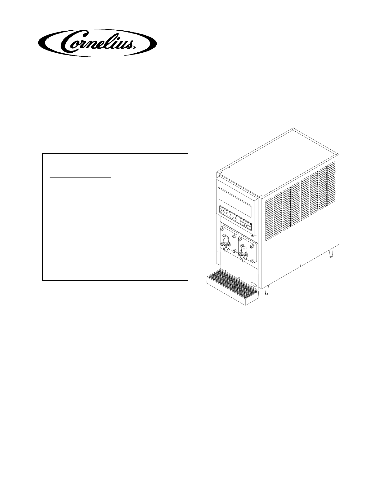
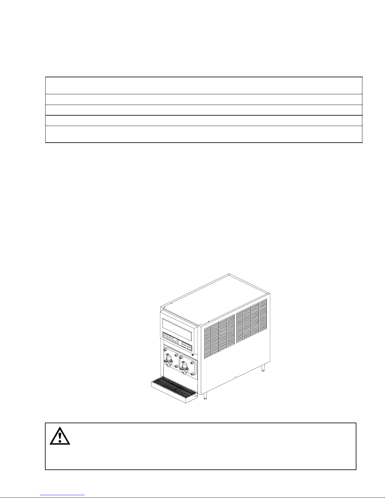
This section gives the description, theory of operation, and design data for the FCB (Frozen Carbonated Beverage) Overcounter Post-Mix Dispenser with V3+ Features (hereafter referred to as a Unit).
UNIT DESCRIPTION
The Unit (see Figure 1) consists basically of two freeze cylinders, each containing an internal beater driven by an
electric motor, one refrigeration system with a 2-horsepower compressor, one carbonator which feeds both carbonator-blender tanks, a timer-controlled automatic hot-gas defrost system to defrost the freeze cylinders, and interconnecting tubing, components, and fittings necessary to regulate, transfer, and dispense the product.
The components are attached to a steel frame and are enclosed in a steel cabinet. The cabinet sides and back
panels are easily removed and the front access door may be opened to facilitate installation and service and
maintenance. A transparent faceplate, with an integral relief valve and a removable self-closing dispensing valve,
is mounted on front of each freeze cylinder. A drip tray, with cup rest, is located directly below the dispensing
valves.
FIGURE 1. FCB OVERCOUNTER POST-MIX DISPENSER
CAUTION: Before shipping, storing, or relocating Unit, syrup systems must be sanitized
and all sanitizing solution must be purged from syrup systems. All water must also be
purged from plain and carbonated water systems. A freezing ambient environment will
cause residual sanitizing solution or water remaining inside Unit to freeze resulting in damage to
internal components.
29921
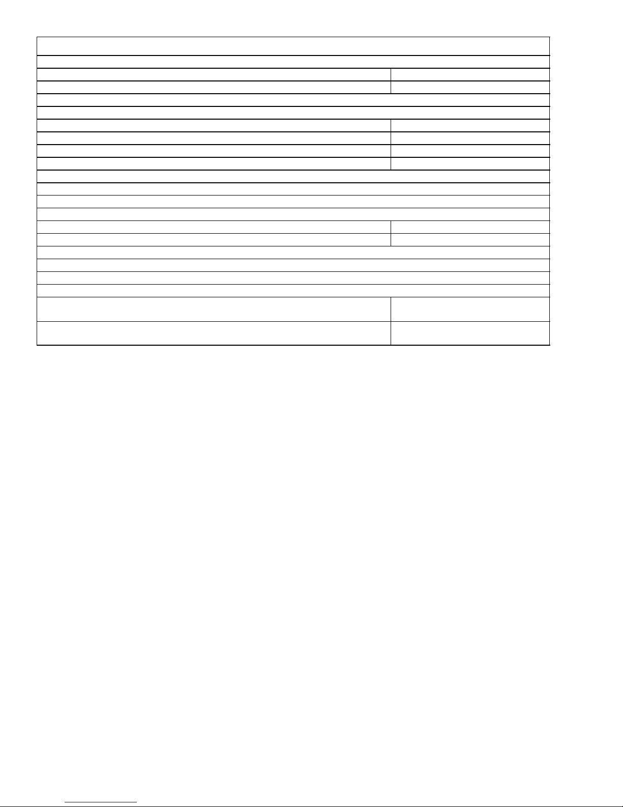
Table 1. Design Data
Unit Part Numbers:
60 HZ Unit 416136XXX
50 HZ Unit 496136XXX
Overall Dimensions:
Height 32 inches
Width 19 inches
Depth W/O Drip tray 31 1/8 inches
Depth W/Drip Tray 36 inches
Shipping Weight (approx) 420 pounds
Refrigeration System:
Compressor Horsepower 2 H.P.
Refrigerant Type And Charge See Unit Nameplate
Ambient Operating Temperature 40° F to 100° F
Electrical Requirements:
Operating Voltage See Unit
Nameplate
Operating Current See Unit
Nameplate
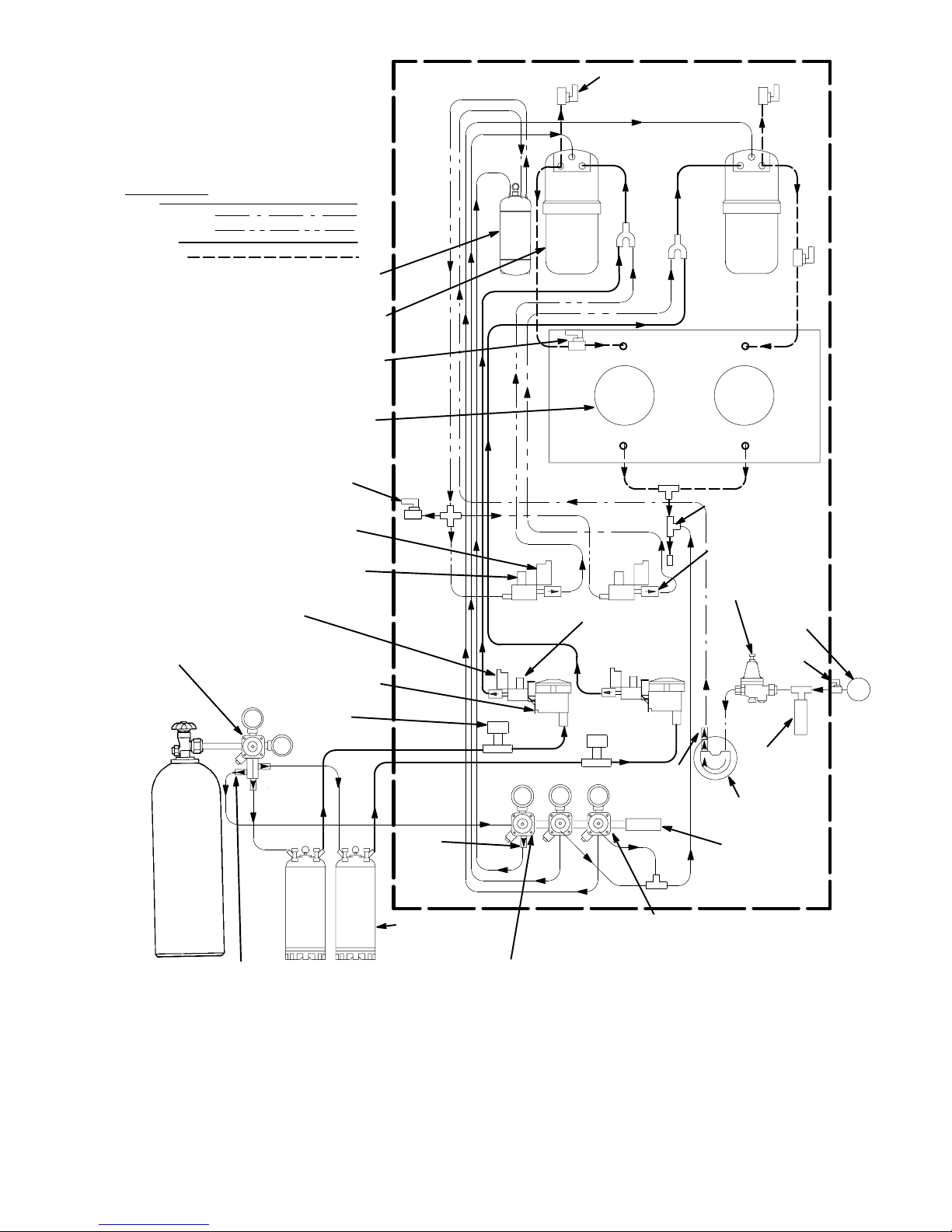
THEORY OF OPERATION
(see Figure 2)
A CO2 cylinder delivers carbon dioxide (CO2) gas to an adjustable primary CO2 regulator assembly which is at-
tached to the cylinder. The primary CO2 regulator assembly in turn delivers CO2 gas to adjustable secondary
CO2 regulators inside the Unit and also to two soft drink tanks. CO2 is delivered from the adjustable secondary
CO2 regulators to the carbonator tank and also to product-blender tanks inside the Unit. CO2 gas pressure
pushes syrup out of the soft drink tanks through the syrup sold-out switches, through adjustable syrup flow regulators, through electrically operated syrup solenoid valves, and on to the product blender tanks.
At the same time, plain water passes through the water pressure regulator and is pumped into the carbonated
water tank by the water pump and is carbonated by CO2 gas pressure also entering the tank. Carbonated water
is pushed by CO2 gas pressure from the carbonated water tank, through adjustable carbonated water flow regulators, through electrically operated carbonated water solenoid valves, and on to the product blender tanks. Carbonated water and syrup enter the tanks properly proportioned (blended) for desired BRIX of dispensed product
by adjustment of the syrup flow regulators.
From product blender tanks, product is pushed by the CO2 gas into the freeze cylinders. The beater in each
freeze cylinder is driven by an electric motor. Scraper blades, attached to the beaters, scrape product from the
cylinder walls as product enters the freeze cylinders and is frozen. Transparent faceplate, attached to the front of
each freeze cylinder, includes a self-closing dispensing valve and a spring-loaded relief valve that protects freeze
cylinder from accidental over pressure. The relief valve is also used to bleed CO2 gas pressure from the freeze
cylinder to the atmosphere when filling the cylinder with product. Electronic sensing on each freeze cylinder motor
provides a means of adjusting viscosity (consistency) of the dispensed product to suit customer preference.
2992 2

Table 2. Accessories and Tools
ACCESSORIES
Installation Kits 1155
Cup Holder 511005000
Cup Holder 511006000
CO2 Changeover Kit 511035000
GENERIC FLAVOR TABS
Cola 1085
Cherry 1086
Orange 1087
Grape 1088
Lemon-Lime 1089
Strawberry 1090
Banana 1091
SERVICE TOOLS
3-gallon Sanitizing Tank 281884000
Spanner Wrench, Dispensing Valve 322859000
Refractometer, 0-30 Scale 511004000
Wrench, Rear Seal Housing 2899
Tool, Drive/Coupler Adjustment Gauge 3810
DEFROST SYSTEMS
The Unit is equipped with both manual and automatic hot-gas defrost systems. The automatic defrost system
may be programmed into the Unit to occur up to nine different times a day with a minimum of two hours between
defrost time settings or the system may be completely turned off.
MANUAL DEFROST SYSTEM
The Manual hot-gas defrost system may be activated at any time by pressing the ‘‘DEFROST’’ switch on front of
the Unit. Refrigeration compressor will operate for a short time, then both freeze cylinders will go into defrost and
defrost for approximately 60 seconds. At the end of the manual defrost cycle, the Unit will return to normal operation. Manual defrost may be cancelled at any time by pressing the ‘‘CANCEL DEFROST’’ switch.
AUTOMATIC DEFROST SYSTEM
The automatic hot-gas defrost system may be programmed into the Unit to occur up to nine different times a day
with a minimum of two hours between defrost settings. At the start of each automatic defrost cycle, refrigeration
compressor will operate for 30 seconds to pump freon out of the freeze cylinders evaporator coils. After freon has
been pumped out of the freeze cylinders evaporator coils, No. 1 freeze cylinders only will go into defrost cycle
and defrost for approximately 7 minutes, then will return to normal operation. This ends the automatic defrost
cycle of No. 1 freeze cylinder. No. 2 freeze cylinder will defrost 30 minutes after the start of No. 1 freeze cylinder.
The next automatic defrost cycle will occur according to the time programmed into the Unit. Automatic defrost
may be cancelled at any time by pressing the ‘‘CANCEL DEFROST’’ switch.
29923

‘‘SLEEP’’ (SLEEP TIME)
‘‘SLEEP’’ (SLEEP TIME) may be programmed into Unit to allow Unit to go into sleep time (Unit shut down, freeze
cylinders beaters and refrigeration systems not operating). At start of sleep time, refrigeration compressor will
operate for 30 seconds to pump freon out of freeze cylinders evaporator coils, then No. 1 freeze cylinder will go
into defrost and defrost for 60 seconds. After No. 1 freeze cylinder has defrosted, No. 2 freeze cylinder will go into
defrost and defrost for 60 seconds. At end of No. 2 freeze cylinder defrost, Unit will shut down and go into sleep
time.
‘‘WAKE UP’’ (WAKE UP TIME)
‘‘WAKE UP’’ (WAKE UP TIME) may be programmed into the Unit to allow Unit to resume normal operation at a
desired time. When programmed wake up time is reached, an alarm will sound for a short duration, then Unit will
resume normal operation.
NOTE: Automatic defrost, sleep time, and wake up time may be used in any combination together or
separately.
2992 4
*WATER PRESSURE REGULATOR IS
FACT ORY ADJUSTED TO 45-PSI AND
SHOULD NOT BE READJUSTED.
**SYRUP SOLD-OUT SWITCHES ARE
FACTORY ADJUSTED AND SHOULD
NOT BE READJUSTED.
LINE LEGEND
CO
2
PLAIN WATER
CARB WATER
SYRUP
PRODUCT
CARBONATOR
PRODUCT BLENDER
TANK(2)
PRODUCT SHUTOFF
VALVE(2)
CYLINDER(2)
CARBONATED WATER
VOLUME SAMPLE VALVE
CARBONATED WATER
SOLENOID VALVE(2)
CARBONATED WATER
FLOW REGULATOR(2)
SYRUP SOLENOID
VALVE(2)
PRIMARY CO
REGULATOR ASS’Y
2
SYRUP SOLD-OUT
FLOAT SWITCH(2)
**SYRUP SOLD-OUT
SWITCH
TANK
FREEZE
PRODUCT SAMPLE
VALVE(2)
SYRUP FLOW
REGULATOR(2)
FREEZE CYLINDER
OVERFLOW TUBE
LIQUID CHECK
VALVE(2)
*WATER PRESSURE
REGULATOR
PLAIN WATER
SOURCE
SHUTOFF
VALVE
CO
2
CYLINDER
CO
CHECK
2
VALVE(3)
CO
2
CHECK
VALVE
SOFT DRINK
TANK(2)
SECONDARY CO2 REGULATOR
TO CARBONATOR TANK
(100-PSI GAGE)
FIGURE 2. FLOW DIAGRAM
WATER
DOUBLE
LIQUID
CHECK
VALVE
PRESSURE
SWITCH
CARBONATOR
WATER PUMP
CO
2
PRESSURE
SWITCH
SECONDARY CO2 REGULATORS
TO PRODUCT BLENDER
TANKS (60–PSI GAGE) (2)
29925

THIS PAGE LEFT BLANK INTENTIONALLY
2992 6

INSTALLATION
This section covers unpacking and inspection, installing LOOSE-SHIPPED PARTS, selecting location, installing
Unit, preparing for operation, and operation.
UNPACKING AND INSPECTION
(see Figure 7)
NOTE: The Unit was thoroughly inspected before leaving the factory and the carrier has accepted and
signed for it. Any damage or irregularities should be noted at time of delivery (or not later than 15 days
from date of delivery) and immediately reported to the delivering carrier. Request a written inspection
report from Claims Inspector to substantiate any necessary claim. File claim with the delivering carrier,
not with IMI Cornelius Inc.
1. After Unit has been unpacked, remove shipping tape and other packing material.
2. Remove Unit sides and back panels as instructed.
3. Remove shipping bolts that secure Unit to skid, then remove skid.
4. Unpack LOOSE-SHIPPED PARTS. Make sure all items are present and in good condition.
Table 3. Loose-Shipped Parts
Item
No. Part No. Name Qty.
1 178025100 Tapered Gasket, White 4
2 322859000 Spanner Wrench, Dispensing Valve 1
3 325216000 Cleaning Brush 1
4 311304000 Tapered Gasket, Black 1
5 317660000 Cup Rest 1
6 325282000 Thread Cutting Screw, Hex Hd.; No. 8 by 18 by 1/2-in. long 2
7 2738 Drip Tray Support, Left 1
8 2739 Drip Tray Support, Right 1
9 317659029 Drip Tray 1
10 326002000 Kit, Drip Tray Drain Hose 1
11 2899 Wrench, Rear Seal Housing 1
12 3810 Tool, Drive/Coupler Adjustment Gauge 1
13 324252000 Leveling Leg 4
14 3247 Spacer, White 2
15 3221 Front Access Panel 1
16 3108 Thread Cutting Screw, Phil Pan Hd; No. 10 by 32 by 1-in. long 2
* Numbers in parentheses are in reference to items in Figure 3.
IDENTIFICATION OF LOOSE-SHIPPED PARTS
1. TAPERED GASKETS, WHITE (item 1) are used to seal connections when connecting Unit product inlet
lines to product tanks and connecting Unit CO2 inlet line to CO2 source.
7
2992

2. SPANNER WRENCH, DISPENSING VALVE (item 2) is used to remove shank nuts securing dispensing
valves to faceplates.
3. CLEANING BRUSH (item 3) is used to clean faceplate relief valves passages.
4. TAPERED GASKET, BLACK (item 4) is used to seal connection when connecting plain water source line to
Unit water inlet line.
5. DRIP TRAY SUPPORTS (item 7) and (item 8) to be installed on front of Unit (See Figure 7) and secured
with Thread Cutting SCREWS (item 6) and THREAD CUTTING SCREWS (Item 18).
6. CUP REST (item 5) to be installed in DRIP TRAY (item 9), then drip tray to be installed on drip tray supports.
7. DRIP TRAY DRAIN HOSE KIT (item 10) to be installed on drip tray as instructed in Instructions provided in
the Kit.
8. WRENCH, REAR SEAL HOUSING (item 11) used to remove the drive shaft/seal assembly from inside the
freeze cylinder.
9. TOOL, DRIVE/COUPLER ADJUSTMENT GAUGE (item 12) is used for servicing the beater motor drive
shaft/ seal assembly (See Figure 13).
10. LEVELING LEGS (item 13) are to be installed on bottom of the Unit.
11. FRONT ACCESS PANEL (item 15) to be installed on front of the Unit (See Figure 7) and secured with
WHITE SPACERS (item 14) and SCREWS (item 16). SPACERS TO BE INSTALLED BETWEEN THE
FRONT PANEL AND THE UNIT FRAME.
ELECTRICAL POWER REQUIREMENTS
IMPORTANT: Before connecting electrical power to the Unit, refer to nameplate and Note if Unit is to be
operated with 50 or 60 Hz power source.
50 HZ UNIT
IMPORTANT: Power circuit voltage across L1 and L2 terminals on contactor inside lower control box,
with refrigeration compressor operating, must be in range of 209-253 VAC, 50Hz single-phase for
proper operation.
A properly grounded 209-253 VAC, 50Hz single-phase electrical circuit connected through a 30-amp minimumrated disconnect switch (not provided) fused at 30-amps (slow-blow) must be available to be connected to the
electrical box located in the lower back side of the Unit.
60 HZ UNIT
IMPORTANT: Power circuit voltage across L1 and L
control box, with refrigeration compressor operating, must be in range of 198-253 VAC, 60 Hz
single-phase for proper operation.
A properly grounded 198-253 VAC, 60Hz single-phase electrical circuit connected through a 30-amp minimumrated disconnect switch (not provided) fused at 30 amps (slow-blow) or circuit connected through an equivalent
HACR circuit breaker must be available to be connected to the electrical box located in lower back side of the
Unit. ALL WIRING MUST CONFORM TO NATIONAL AND LOCAL CODES. MAKE SURE UNIT IS PROPERLY
GROUNDED.
terminals on contactor inside lower electrical
2
SELECTING LOCATION
IMPORTANT: Unit operating ambient temperature MUST NOT EXCEED 100° F. Operating ambient in
excess of 100°F will automatically void the factory warranty and will eventually result in Unit failure.
Several means are available to achieve proper ambient temperature and air circulation around the Unit
which are wall air intake grilles and ceiling exhaust fans, air conditioning, etc. Consult local codes.
2992 8

Locate the Unit so the following requirements are satisfied.
1. Locate close to a filtered plain water inlet supply line with a minimum water pressure of 12-psig.
NOTE: The FCB Dispenser refrigeration system is equipped with a condenser coil that is cooled by two
condenser coil fans. Circulating air, required to cool the refrigeration system’s condenser coil, is drawn
in through the grilled panel on the right-hand side and is exhausted out through the opposite side
grilled panel. Restricting air circulation through the Unit will decrease its cooling efficiency.
2. When installing Unit in it’s operating position, do not allow obstructions to block sides, top, and front of the
Unit which will block off cooling air intake to the inside of the Unit. Air flow through the Unit must be present
to provide adequate cooling for the refrigeration system.
Locate the Unit to provide the following clearances:
Top of unit Open (24 inches min.)
Back side 0-inches
Sides 6 inches (min.)
Front Open
INSTALLING UNIT
INSTALLING LEVELING LEGS
Very carefully, tilt Unit up and install LEVELING LEGS (item 13) on four corners of the Unit base.
INSTALLING DRIP TRAY SUPPORTS (ITEM 7) AND (ITEM 8)
1. Install DRIP TRAY SUPPORT, LEFT (item 7) and DRIP TRAY SUPPORT, RIGHT (item 8) on front of the
Unit and secure with SCREWS (item 6) See Figure 7.
2. Place DRIP TRAY (item 9) on drip tray supports.
3. Place CUP REST (item 5) in drip tray.
INSTALLING DRIP TRAY DRAIN HOSE KIT (ITEM 10)
Install DRIP TRAY DRAIN HOSE KIT (item 10) on Unit as instructed in Installation Instructions provided with
the Kit.
PREPARING UNIT FOR CONNECTION TO SYRUP, CO2, AND CITY PLAIN WATER
SOURCES
Route coiled up syrup, CO2, and plain water lines out through hole provided in the Unit base.
INSTALLING PRIMARY CO2 REGULATOR ASSEMBLY ON CO
(see Figure 2)
WARNING: To avoid personal injury and/or property damage, always secure CO2 cylinder in
upright position with a safety chain to prevent it from falling over. Should the valve become
accidentally damaged or broken off, CO2 cylinder can cause serious personal injury.
CYLINDER
2
9
2992
1
2
3
4
5
6
7
8
9
10
11
1213
14
15
1617
18
19
20
21
22
23
24
25
26
27
10
2992
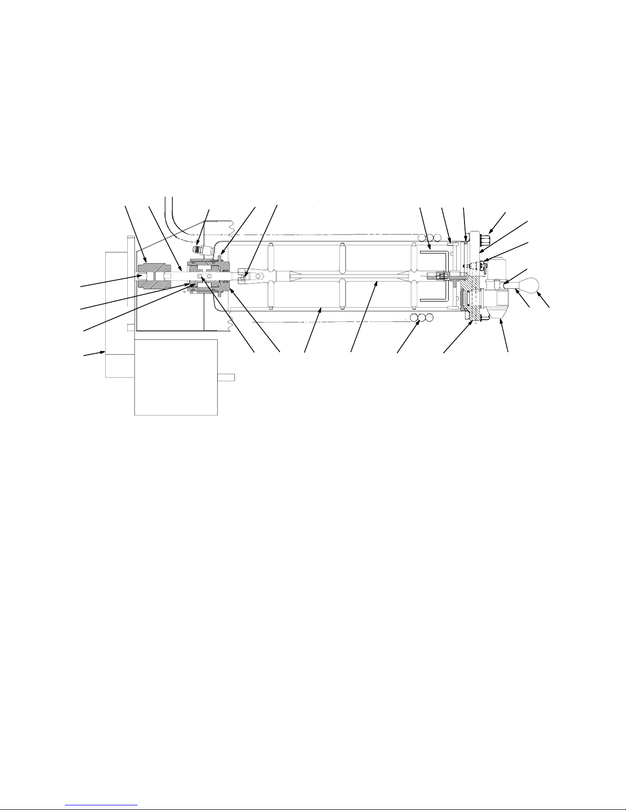
1 Product Inlet Fitting 2 Scraper Blade (2) 3 Evaporator Coil
4 Relief Valve Port 5 O-Ring 6 Flatwasher (4)
7 Hex Nut (4) 8 Faceplate 9 Relief Valve
10 Valve Lever 11 Knob 12 Dispensing V alve
13 Beater 14 Allen Head Setscrew 15 Beater Shaft Coupling
16 Drive Pin 17 Bearing Housing Locking Tab (4) 18 Bearing Retainer
19 Beater Motor Drive Shaft 20 Beater Drive Motor 21 Drive Shaft Assembly
22 Viscosity Sensor 23 Spinner 24 Spring
25 Shaft Release 26 Bearing 27 Bearing Housing
FIGURE 3. FREEZE CYLINDER CUTAWAY VIEW

BEATER
KEY ON END
OF POST
KEY ON END
OF POST
KEY SLOT
ON BLADE
SCRAPER BLADES MUST BE MOUNTED TO THE
BEATER BODY AS SHOWN USING THE PERFORATED
EDGE AS THE LEADING EDGE. LINE UP KEY ON END
OF POSTS WITH KEY SLOT IN SCRAPER BLADES.
FIGURE 4. BEATERS AND SCRAPER BLADES INSTALLATION
WARNING: CO2 displaces oxygen. Strict attention must be observed in the prevention of
CO2 (carbon dioxide) gas leaks in the entire CO2 and soft drink system. If a CO2 gas leak is
suspected, particularly in a small area, immediately ventilate the contaminated area before
attempting to repair the leak. Personnel exposed to high concentration of CO2 gas will experience
tremors which are followed rapidly by loss of consciousness and suffocation.
1. Unscrew protector cap (with chain attached) from CO2 cylinder valve. Open CO2 cylinder valve slightly counterclockwise to blow any dirt or dust from outlet fitting before installing primary CO2 regulator, then close
valve.
2. Remove shipping plug from primary CO2 regulator assembly coupling nut and make sure gasket is in place
inside nut. Install regulator assembly on CO2 cylinder so gages can be easily read, then tighten coupling nut.
DO NOT OPEN CO2 CYLINDER VALVE AT THIS TIME.
CONNECTING SOFT DRINK TANKS CO2 LINES TO PRIMARY CO2 REGULATOR
ASSEMBLY
(see Figure 2)
1. Connect soft drink tanks CO2 lines to primary CO2 regulator manifold assembly as shown in Figure 2.
2. Install gas quick disconnects on ends of soft drink tanks CO2 lines. DO NOT CONNECT CO2 LINES TO
TANKS AT THIS TIME.
11 2992

PREPARING UNIT SYRUP INLET LINES FOR CONNECTION TO SOFT DRINK TANKS
(see Figure 2)
1. Route Unit syrup inlet lines labeled No. 1 and No. 2 to soft drink tanks location.
2. Install liquid quick disconnects on ends of Unit syrup inlet lines. DO NOT CONNECT SYRUP LINES TO
SOFT DRINK TANKS AT THIS TIME.
CONNECTING CO2 SOURCE LINE TO UNIT CO2 INLET LINE
(see Figure 2)
1. Connect and route a CO2 source line from the primary CO2 regulator up to the Unit.
2. Connect the CO2 source line to the Unit CO2 inlet line. DO NOT TURN ON THE CO2 SOURCE AT THIS
TIME.
CONNECTING CITY PLAIN WATER SOURCE LINE TO UNIT
NOTE: The Units require connection to a city plain water source line with a minimum water pressure of
12-psig. IMI Cornelius Inc. recommends that a water shutoff valve and water filter be installed in the City
plain water source line (see Figure 2). A Cornelius Water Filter (P/N 313860000) and Quick Disconnect
Set (P/N 313867-000) are recommended.
1. Connect and route city plain water source line up to the Unit.
2. Before connecting the city plain water source line to the Unit, open shutoff valve in city plain water source
line for a period of time to flush out any metal shavings, then close valve.
3. Connect the city plain water source line to the Unit plain water inlet line. Seal connection with TAPERED
GASKET, BLACK (item 4). DO NOT OPEN THE CITY PLAIN WATER SOURCE LINE SHUTOFF VALVE AT
THIS TIME.
CONNECTING ELECTRICAL POWER CIRCUIT TO THE UNIT
(see Figure 16)
WARNING: Make sure Unit 30-amp (60 Hz Unit) or 50-amp (50 Hz Unit) minimum-rated
disconnect switch (not provided) or equivalent HACR circuit breaker is in ‘‘OFF’’ position.
60 HZ Unit.
IMPORTANT: Power circuit voltage across L1 and L2 terminals on the contactor inside the lower electrical
control box, with refrigeration compressor operating, must be in the range of 198-253 VAC, 60 Hz
single-phase for proper operation. Use No. 10 AWG copper wire, or larger, depending upon line length,
in suitable conduit or BX sheath. POWER CIRCUIT TO UNIT MUST BE MADE UP OF COPPER
CONDUCTORS AND ALL WIRING MUST CONFORM TO NATIONAL AND LOCAL CODES.
50 HZ Unit.
IMPORTANT: Power circuit voltage across L1 and L2 terminals on the contactor inside the lower electrical
control box, with refrigeration compressor operating, must be in the operating range of 209-253 VAC, 50
Hz single-phase for proper operation.
122992

1. Remove cover from electrical box located in lower back side of the Unit.
WARNING: The Unit must be electrically grounded to avoid possible fatal electrical shock
or serious injury to the operator. A green screw, with lock washer, is provided inside the
electrical box to connect power circuit ground wire which will electrically ground the Unit.
2. Connect electrical power circuit from a 30-amp (60-Hz Unit) or 30-amps (50-Hz Unit) minimum-rated disconnect switch (not provided) fused at 30-amps (60- Hz Unit) or 30-amps (50-Hz Unit) (slow-blow) or through an
equivalent HACR circuit breaker to electrical wires inside the electrical control box. Secure the connections
with red wire nuts. MAKE SURE GROUND WIRE IS CONNECTED TO GREEN GROUND SCREW INSIDE
THE ELECTRICAL BOX.
3. Install the electrical box cover and secure with screws.
PREPARATION FOR OPERATION
TURNING ON ELECTRICAL POWER TO UNIT
Turn on electrical power to the Unit. Operational status of the Unit is now being displayed as fault messages on
the control panel message display. The following fault messages will be continuously displayed at 2-second intervals until necessary operation requirements are satisfied.
‘‘OFF 1’’ (Beater Motor No. 1 not operating)
‘‘OFF 2’’ (Beater Motor No. 2 not operating)
‘‘H2O OUT’’ (No water supply to Unit)
‘‘CO2 OUT’’ (No CO2 gas supply to Unit)
‘‘SYRUP 1’’ (No syrup supply to Unit No. 1 syrup system)
‘‘SYRUP 2’’ (No syrup supply to Unit No. 2 syrup system)
TURNING ON CO2 SUPPLY TO the UNIT
1. Open CO2 cylinder valve slightly to allow lines to slowly fill with gas, then open valve fully to back seat valve.
Back-seating valve prevents leakage around valve shaft.
ADJUSTING PRIMARY CO
IMPORTANT: If bag-in-box syrup supply system will be connected to the Unit instead of soft drink tanks,
primary CO2 regulator (see Figure 2) must be adjusted to no less than 80-psi.
1. Adjust primary CO2 regulator (see Figure 2) by turning regulator adjusting screw to the right (clockwise) until
regulator pressure reads 80 to 100-psig.“OUT OF CO
should have gone out.
2. Using a flat blade screwdriver, turn lock counterclockwise to unlock the front access door (see Figure 7),
then open the door for access to the product blender tanks relief valves (see Figure 8).
3. Pull up on product blender tanks relief valves (see Figure 8) to purge air from tanks.
ADJUSTING PRODUCT BLENDER TANKS SECONDARY CO
Check product blender tanks secondary CO2 regulators with 60-psi gages (see Figures 2 and 8) for pressure setting which should be set at 25 to 30-psi for best textured product. If further adjustment is necessary, adjust as
instructed.
REGULATOR
2
” warning light on control panel message display
2
2
ADJUSTING CARBONATOR SECONDARY CO
IMPORTANT: The carbonator secondary CO2 regulator must be adjusted 25-psi higher or more above the
product blender tanks secondary CO2 regulators pressure settings. Carbonated water and syrup
pressures must be able to overcome and vent product blender tanks head pressures while tanks are
filling with carbonated water and syrup. Carbonator tank secondary CO2 regulator not adjusted high
enough will cause decreased flow of carbonated water into the blender tanks, which will increase brix of
the dispensed product.
REGULATOR
2
13 2992

1. Adjust carbonator secondary CO2 regulator, with 100-psi gage, by turning regulator adjusting screw to the
right (clockwise) until gage reads 50 to 60-psi.
2. Pull up on carbonator tank relief valve plastic cover to purge air from tank.
STARTING FCB AND ADJUSTING WATER-TO-SYRUP “RATIO” (BRIX) OF DISPENSED
PRODUCT
1. Open shutoff valve in city plain water line connected to the Unit. Check for water leaks and tighten or repair
leaks if evident. ‘‘H
sages will continue to be displayed.
IMPORTANT: Product shutoff valves, located in lines leading from product blender tanks to freeze
cylinders (see Figure 2 and 8), must be closed at this time. Closing valves prevents product from filling
freeze cylinders while checking BRIX of product in product blender tanks.
2. Close product shutoff valves, located in lines leading from product blender tanks to freeze cylinders, to prevent product from entering cylinders.
IMPORTANT: The following CO2 and liquid disconnects disconnecting and connecting procedure for
soft drink tank replacement or filling soft drink tank in place must be performed in order as follows:
To disconnect soft drink tank from Unit syrup system.
A. Disconnect liquid disconnect from soft drink tank. NOTE - Disconnecting liquid quick discon-
nect from soft drink tank first prevents syrup from backflowing through Unit syrup flow regulator which may alter regulator adjustment.
O OUT’’ fault message should have gone out but ‘‘SYRUP 1’’, and ‘‘SYRUP 2’’ fault mes-
2
B. Second, disconnect CO2 quick disconnect from soft drink tank.
To connect soft drink tank into Unit syrup system.
C. First, connect CO2 quick disconnect to soft drink tank to pressurize the tank.
D. Second, connect liquid quick disconnect to the soft drink tank.
3. Pressurize soft drink tanks containing syrup, then connect tanks into Unit syrup systems.“OFF 1”, “OFF 2”,
“SYRUP 1”, and “SYRUP 2” fault messages will continue to be displayed.
4. The following steps A through J are instructions for adjusting the Water-to-Syrup “Ratio” (Brix) of the dispensed product on on of the systems.
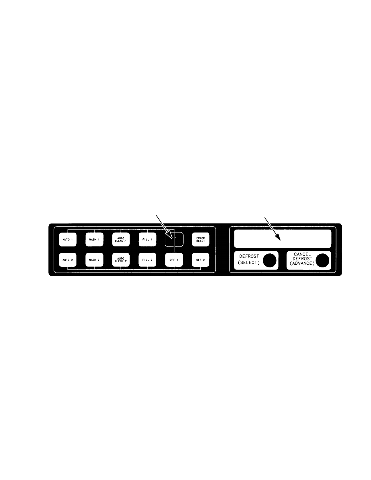
NOTE: The Unit control panel assembly is equipped with a hidden “SECURITY SWITCH” located between “FILL 1” and “ERROR RESET” control switches (see Figure 5). Pressing in and holding
“SECURITY SWITCH” for 3 seconds deactivates the control switches preventing tampering with Unit
normal operation. To reactivate the control switches, press in and hold the “SECURITY SWITCH” for 3
seconds.
NOTE: The adjustable carbonated water flow regulators (see Figure 2 and 11 ) located in their respective
systems, control carbonated water flow rate to the product blender tanks. The water flow regulators are
factory adjusted at 1.3 0.05 oz/sec and should not normally require adjustment. If adjustment is necessary, adjust as instructed.
A. Press ‘‘FILL 1’’ switch to fill No. 1 syrup system sold-out float. ‘‘SYRUP 1’’ fault message will go out and
‘‘FILL 1’’ fault message will come on. ‘‘OFF 1’’, ‘‘OFF 2’’, and ‘‘SYRUP 2’’ fault messages will continue to
be displayed.
B. Press ‘‘AUTO BLEND 1’’ switch to fill No. 1 system product blender tank with product. ‘‘FILL 1’’ fault
message will go out when ‘‘AUTO BLEND 1’’ switch is pressed. When product blender tank is full, press
‘‘FILL 1’’ switch to prevent more product from entering tank. ‘‘OFF 1’’, ‘‘OFF 2’’, and ‘‘SYRUP 2’’ fault
messages will continue to be displayed.
C. Open No. 1 product blender tank product sample valve (see Figure 2 and 8) and take a sample (approx-
imately 6 ounces) of product in a cup or glass.
142992
NOTE: Temperature compensated hand-type refractometers (P/N 511004000) are available from The Cornelius Company.
D. Check product BRIX with a temperature compensated hand-type refractometer. BRIX should read 13 ±
1. If BRIX is not within tolerance, adjust white syrup flow regulator for No. 1 syrup system as follows:
E. Turn regulator adjusting screw to the left (counterclockwise) no more than 1/8-turn at a time to reduce
syrup flow rate or turn screw to the right (clockwise) no more than 1/8-turn to increase flow rate.
F. Place container under No. 1 product sample valve. Open valve to purge product out of product blender
tank, line, and valve, then close valve. ‘‘OFF 1’’, ‘‘OFF 2’’, and ‘‘SYRUP 2’’ will continue to be displayed.
G. Press ‘‘AUTO BLEND 1’’ switch to run new batch of product into product blender tank. When product
blender tank is full, press ‘‘FILL 1’’ switch to prevent more product from entering product blender tank.
‘‘OFF 1’’, ‘‘OFF 2’’, and ‘‘SYRUP 2’’ fault messages will continue to be displayed.
H. Repeat steps C and D preceding to check product sample for BRIX.
I. Repeat steps F through H preceding until proper BRIX adjustment is achieved.
J. Repeat steps A through I preceding to adjust BRIX of dispensed product on No. 2 system. After com-
pleting BRIX adjustment on No. 2 system, only the ‘‘OFF 1’’ and ‘‘OFF 2’’ fault messages should contin-
ue to be displayed.
NOTE: Syrup systems may be sanitized at this time as instructed.
HIDDEN SECURITY
SWITCH
FIGURE 5. CONTROL PANEL ASS’Y
MESSAGE DISPLAY
FILLING FREEZE CYLINDERS WITH PRODUCT
1. Open product shutoff valves, located in lines leading from product blender tanks to freeze cylinders.
2. Press ‘‘AUTO BLEND 1’’ and ‘‘AUTO BLEND 2’’ switches to begin filling freeze cylinders. Open freeze cylinders faceplates relief valves to bleed air from cylinders while filling with product, then close valves. Do not
relieve freeze cylinder pressure too fast or product will foam excessively in cylinder and lose carbonation.
CHECKING UNIT FOR SYRUP, CO2, OR PLAIN WATER LEAKS
1. Inspect the entire Unit and the entire system for syrup, CO2,or plain water leaks and repair if evident.
2. Install the Unit back and side panels.
3. Install Unit front access panel (see Figure 7) and secure with THREAD CUTTING SCREWS (item 16) and
WHITE SPACERS (ITEM 14).
4. Close front access door, then use a flat blade screwdriver to turn lock clockwise to lock the door.
15 2992

PLACING UNIT IN OPERATING LOCATION
IMPORTANT NOTICE
The FCB Dispensers manufactured prior to the models documented in this manual were elevated
in the front (dispensing valve side) 1/4 to 3/8-inch higher than the back when placing the Unit in
operating position to eliminate gas pockets being trapped inside the freeze cylinders. Due to a
redesign of the foam pack in the models documented in this manual, elevating the front of the
Dispenser is no longer required. The Dispenser must be leveled at time of placing in operating
location.
1. Disconnect electrical power from Unit at the electrical power source disconnect switch.
IMPORTANT: When installing Unit in it’s operating position, do not allow obstructions to block sides,
top, and front of the Unit which will block off cooling air intake to the inside of the Unit. Air flow through
the Unit must be present to provide adequate cooling for the refrigeration system. Refer to SELECTING
LOCATION for sides, top, and front clearances to be observed when placing Unit in operating position.
2. Referring to the preceding NOTE, very carefully, place the Unit in operating location.
3. Make sure the Unit is sitting level. The Unit may be leveled by using a carpenter’s level and adjusting the
four leveling legs installed on the Unit during installation.
4. Restore Unit to operation by connecting electrical power at the electrical power source disconnect switch.
ADJUSTING BEATER MOTOR CURRENT (EITHER SIDE)
Adjusting beater motor current (either side) procedure is very important and must be performed as instructed. Be
sure you fully understand the instructions before performing the current adjustments or doing any preventative
maintenance current readings check.
IMPORTANT: Any current adjustments or preventative maintenance current readings check on the beater
motor current (either side) must be performed with both freeze cylinders fully defrosted. A partially
defrosted freeze cylinder will cause false current readings to be displayed on the message display.
Adjust beater motor current (either side) as follows:
1. Using a flat blade screwdriver, turn lock counterclockwise to unlock the front access door (see Figure 7),
then open the door.
2. Remove four screws securing the upper electrical control box cover (control box located on back of the front
access door). Remove cover for access to the master circuit board
(see Figure 6 ).
3. Place No. 4 ‘‘BEATER MOTOR CURRENT READOUT’’ switch on DIP SWITCH assembly on master circuit
board (see Figure 6) in ‘‘ON’’ position. Both freeze cylinders beater motors will start and operate and beaters
motors current ratings will be displayed on message display.
162992

4. Display should be adjusted to read A150 B150 ± 2 by adjusting MOTOR CURRENT ADJUSTMENTS located on No. 1 and No. 2 relay circuit boards (see Figure 6). These figures will fluctuate slightly with variations in line voltage and motor loads.
5. After completion of adjusting beater motor current to A150 B150 ± 2, make sure No. 5 ‘‘MOTOR CURRENT
SELF-CALIBRATION’’ switch on DIP SWITCH assembly on master circuit board (see Figure 6) is in ‘‘OFF’’
position. No. 5 switch in ‘‘OFF’’ position allows the ‘‘MOTOR CURRENT’’ SELF-CALIBRATION’’ electronics
to automatically self-calibrate the beaters motors currents at completion of each defrost cycle.
CAUTION: IF NO. 4 ‘‘BEATER MOTOR CURRENT READOUT’’ SWITCH ON DIP SWITCH
assembly is placed in ‘‘ON’’ position and beater motor current readings were A155 B145
and switch was then placed back in ‘‘OFF’’ position without readjusting to A150 B150 ± 2,
beater motor current has just been reset at A155 B145. Operating the FCB Dispenser at these
current readings may have serious effects on its operation.
ANY TIME THE NO. 4 ‘‘BEATER MOTOR CURRENT READOUT’’ SWITCH ON DIP SWITCH ASSEMBLY IS
PLACED IN ‘‘ON’’ POSITION, THE BEATER MOTOR CURRENT READINGS MUST BE READJUSTED TO
A150 B150 ± 2 AS INSTRUCTED, THEN SWITCH MUST BE PLACED BACK IN THE ‘‘OFF’’ POSITION.
6. Close front access door, then use a flat blade screwdriver to turn lock clockwise to lock the door.
7. Install FRONT ACCESS PANEL (item 15) and SPACERS (item 14) and secure with THREAD CUTTING
SCREWS (item 16). MAKE SURE SPACERS ARE INSTALLED BETWEEN THE FRONT ACCESS PANEL
AND THE UNIT FRAME (SEE FIGURE 7).
ADJUSTMENT AND PROGRAMMING MAIN MENU SELECTIONS,
COMPONENTS “DIAGNOSE’’ (DIAGNOSTIC MODE), AND (‘‘TOTALS”
DISPLAYED CYCLES AND HOURS TOTALS) INTO UNIT
NOTE: The Unit control panel switches are as shown in Figure 5.
The following instructions outline adjustments and programming main menu selections, components ‘‘DIAGNOSE’’ (DIAGNOSTIC MODE), and ‘‘TOTALS” (DISPLAYED CYCLES AND HOURS TOTALS) into the Unit.
NOTE: Plain water, CO2 and syrup supplies to Unit must be satisfied to turn off ‘‘H2O OUT’’, ‘‘CO2 OUT’’,
‘‘SYRUP 1’’, and ‘‘SYRUP 2’’ fault messages on message display before adjustments and programming
procedures can be performed on the Unit.
PROGRAMMING MAIN MENU SELECTION ONTO MESSAGE DISPLAY
The MAIN MENU SELECTIONS (see 4) may be brought up on the message display as follows:
1. Press ‘‘AUTO 1’’, ‘‘WASH 1’’, and ‘‘BLEND 1’’ control switches (see Figure 5) at the same time and hold
them pressed for a minimum of 1/2 second to bring up MAIN MENU SELECTIONS on message display. The
word ‘‘CLOCK’’ will appear on display. You are now in the MAIN MENU SELECTIONS as shown in Table 4.
To advance through the MENU SELECTIONS, repeatedly press the ‘‘CANCEL DEFROST’’ (ADVANCE)
switch. Once you reach the desired selection, press the ‘‘DEFROST’’ (SELECT) switch to lock in on the
selection.
NOTE: To exit MENU SELECTION and return to MAIN MENU SELECTIONS, press ‘‘ERROR RESET’’ (RESET) switch. Press ‘‘ERROR RESET (RESET) switch again to exit from MAIN MENU SELECTIONS.
SETTING CLOCK (TIME OF DAY)
NOTE: The CLOCK (TIME OF DAY) must be programmed into Unit before ‘‘DEFROST’’ (AUTOMATIC),
‘‘SLEEP’’ (SLEEP TIME), and ‘‘WAKE UP’’ (WAKE UP TIME) can be programmed into the Unit.
17 2992
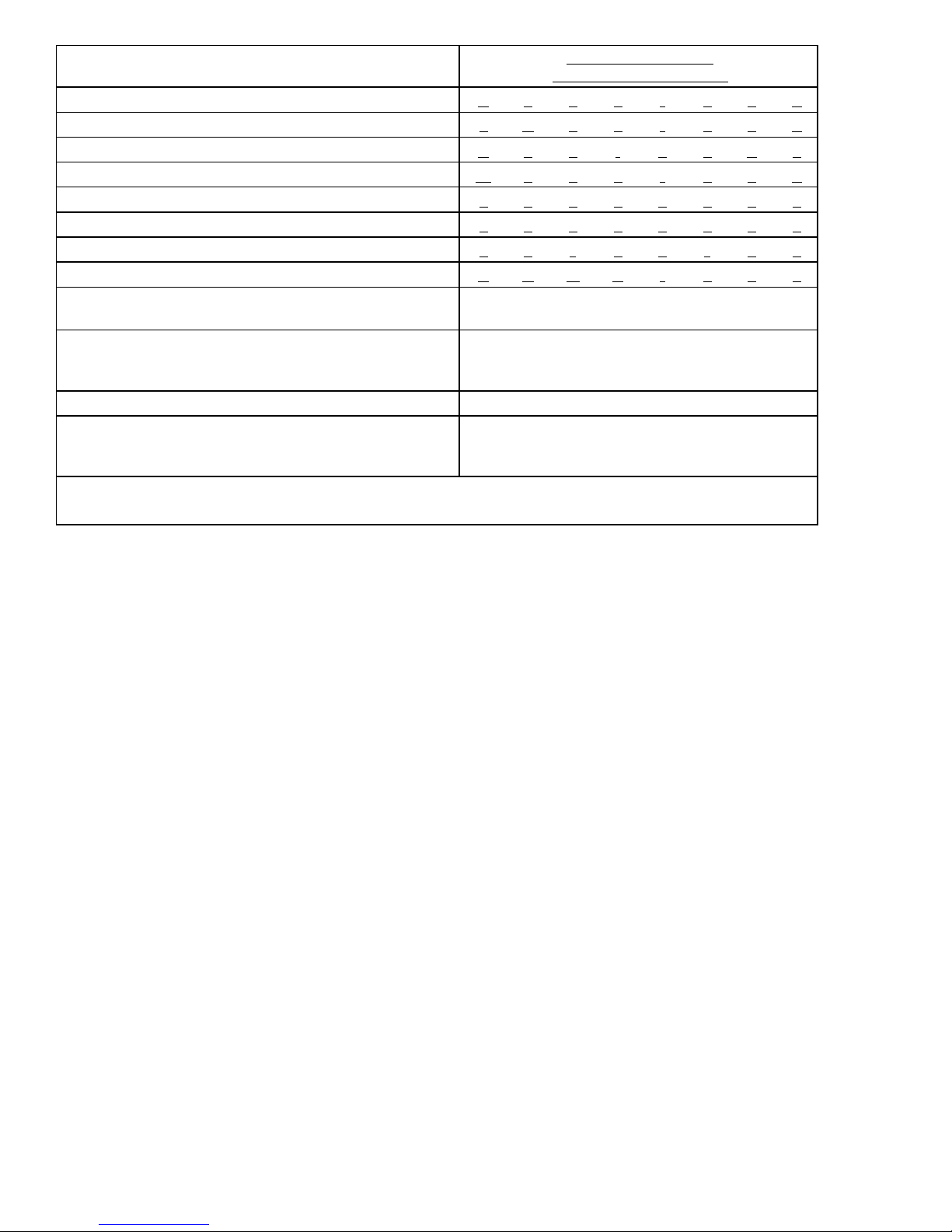
MENU SELECTIONS
“CLOCK” (TIME OF DAY) see note below C _ 1 2 - 0 0 A
“DEFROST” (AUTOMATIC) 3 D 1 0 - 0 0 A
“SLEEP” (SLEEP TIME) S 1 2 - 3 0 A _
“WAKE UP” (WAKE UP TIME) W _ 0 7 - 1 5 A
“VIS SET” (PRODUCT VISCOSITY SETTING) 1 2 _ _ _ _ 1 0
“VIS READ” (ACTUAL VISCOSITY READOUT) 1 6 _ _ _ _ 1 1
“SENSORS (TEMPERATURES READOUT) 7 5 * 7 5 * 7 5
“VOLTAGE” (DISPLAYED VOLTAGE READOUT) V R M S * 2 3 0
“DIAGNOSE” (DIAGNOSTIC MODE)
“TOTALS”
“MOTORS” (BEATER MOTOR MANUFACTURER) See Table 6
“REF TYPE” (REFRIGERANT TYPE)
NOTE: The “CLOCK” (TIME OF DAY) must be programmed into the Unit before “DEFROST” (AUTOMATIC) “SLEEP” (SLEEP TIME), and “WAKE UP” (WAKE UP TIME) will function.
See Programming Components Diagnose into
Unit.
See Table 7 and programming “TOTALS”
(DISPLAYED CYCLES AND HOURS TOTALS)
into unit.
See PROGRAMMING PROPER
REFRIGERANT TYPE INTO UNIT
ELECTRONICS.
MESSAGE DISPLAY
(EXAMPLE READOUTS)
TABLE 4. MAIN MENU SELECTIONS
Program ‘‘CLOCK’’ (TIME OF DAY) into Unit as follows:
1. Refer to PROGRAMMING MAIN MENU SELECTIONS ONTO MESSAGE DISPLAY and bring up ‘‘CLOCK’’
on display. Press ‘‘DEFROST’’ (SELECT) switch to lock in on selection.
2. Press ‘‘CANCEL DEFROST’’ (ADVANCE) switch to bring up flashing hour number on display.
3. Press ‘‘CANCEL DEFROST’’ (ADVANCE) switch to advance hours on display to desired hour. Press ‘‘DE-
FROST’’ (SELECT) switch to lock in hour on display.
4. After hour (time of day) has been locked in on message display, minute numbers will be flashing on display.
Press ‘‘CANCEL DEFROST’’ (ADVANCE) switch to advance minute numbers to desired minutes (time of
day). Press ‘‘DEFROST’’ (SELECT) switch to lock in minute (time of day) on display.
5. Press ‘‘ERROR RESET’’ switch two times to exit from MENU SELECTION.
PROGRAMMING ‘‘DEFROST’’ (AUTOMATIC) SETTINGS INTO UNIT
The automatic defrost system may be programmed into the Unit to occur up to nine different times during a day
with a minimum of two hours between defrost time settings. Program automatic defrost time settings into the Unit
as follows:
1. Refer to PROGRAMMING MAIN MENU SELECTIONS ON TO MESSAGE DISPLAY and bring up ‘‘DE-
FROST’’ on message display. Press ‘‘DEFROST’’ (SELECT) switch to lock in on selection.
2. Press ‘‘CANCEL DEFROST’’(ADVANCE) switch to bring up flashing hour number on display.
3. Press ‘‘CANCEL DEFROST’’(ADVANCE) switch to advance hours on display to desired hour. Press ‘‘DE-
FROST’’(SELECT) switch to lock in hour on display.
4. After hour (time of day) has been locked in on message display, minute numbers will be flashing on display.
Press ‘‘CANCEL DEFROST’’ (ADVANCE) switch to advance minute numbers to desired minutes (time of
day). Press ‘‘DEFROST’’ (SELECT) switch to lock in minute (time of day) on display.
182992

5. Press ‘‘DEFROST’’ (SELECT) switch, then repeat steps 2, 3, and 4 to program in next defrost time setting.
MAKE SURE A MINIMUM OF TWO HOURS IS MAINTAINED BETWEEN DEFROST TIME SETTINGS. IF
A TIME SETTING OF LESS THAN TWO HOURS IS PROGRAMMED INTO THE UNIT, A MOMENTARY
‘‘ERROR’’ MESSAGE WILL APPEAR ON THE MESSAGE DISPLAY WHEN OPERATOR TRIES TO EXIT
‘‘DEFROST’’. THE PROGRAM WILL NOT ALLOW THE OPERATOR TO EXIT THE DEFROST SETTING
UNTIL THE LESS THAN 2-HOUR DEFROST TIME IS CORRECTED. THE OPERATOR MUST PRESS
‘‘CANCEL DEFROST’’ (ADVANCE) SWITCH, THEN REPEAT STEPS 2, 3, and 4 TO PROGRAM CORRECTED DEFROST TIME INTO UNIT.
6. Repeat step 5 as many times as necessary to program desired number of defrost time settings into the Unit.
7. Press ‘‘ERROR RESET’’ switch two times to exit from MENU SELECTIONS.
PROGRAMMING ‘‘SLEEP’’ (SLEEP TIME) INTO UNIT
‘‘SLEEP’’ (SLEEP TIME) may be programmed into Unit to occur any time of the day after Unit automatic defrost
cycle has occurred. Unit will shut down (go into sleep time) and will not wake up (return to normal operation) until
programmed ‘‘WAKE UP’’ (WAKE UP TIME) has occurred. Program ‘‘SLEEP’’ (SLEEP TIME) into Unit as follows:
1. Refer to PROGRAMMING MENU SELECTIONS ONTO MESSAGE DISPLAY and bring up ‘‘SLEEP’’ on
message display. Press ‘‘DEFROST’’ (SELECT) switch to lock in on selection.
2. Press ‘‘CANCEL DEFROST’’ (ADVANCE) switch to bring up flashing hour number on display.
3. Press ‘‘CANCEL DEFROST’’ (ADVANCE) switch to advance hours on display to desired hour. Press ‘‘DE-
FROST’’ (SELECT) switch to lock in hour on display.
4. After hour (time of day) has been locked in on message display, minute numbers will be flashing on display.
Press ‘‘CANCEL DEFROST’’ (ADVANCE) switch to advance minute numbers to desired minutes (time of
day). Press ‘‘DEFROST’’ (SELECT) switch to lock in minutes (time of day) on display.
5. Press ‘‘ERROR RESET’’ switch two times to exit from MENU SELECTIONS.
PROGRAMMING ‘‘WAKE UP’’ (WAKE UP TIME) INTO UNIT
‘‘WAKE UP’’ (WAKE UP TIME) may be programmed into Unit to occur any time of the day to wake Unit up (return
to normal operation) after ‘‘sleep time’’ has occurred. Program ‘‘WAKE UP’’ into Unit as follows:
1. Refer to PROGRAMMING MAIN MENU SELECTIONS ONTO MESSAGE DISPLAY and bring up ‘‘WAKE
UP’’ on message display. Press ‘‘DEFROST’’ (SELECT) switch to lock in on selection.
2. Press ‘‘CANCEL DEFROST’’ (ADVANCE) switch to bring up flashing hour number on display.
3. Press ‘‘CANCEL DEFROST’’ (ADVANCE) switch to advance hours on display to desired hour. Press ‘‘DE-
FROST’’ (SELECT) switch to lock in hour on display.
4. After hour (time of day) has been locked in on message display, minute numbers will be flashing on display.
Press ‘‘CANCEL DEFROST’’ (ADVANCE) switch to advance minute numbers to desired minutes (time of
day). Press ‘‘DEFROST’’ (SELECT) switch to lock in minutes (time of day) on display.
5. Press ‘‘ERROR RESET’’ switch two times to exit from MENU SELECTIONS.
19 2992

SWITCH
NO. FUNCTION
1 POINT OF SALE MESSAGE SELECT See Table 7
2 POINT OF SALE MESSAGE SELECT See Table 7
3 See NOTE.
4 BEATER MOTOR CURRENT READOUT ON- Display current readout.
OFF- No displayed current readout.
5 MOTOR CURRENT SELF-CALIBRATION ON- Disabled.
OFF- Operating.
6 NOT USED
7 NOT USED
8 NOT USED
9 DEFROST ON- Hot gas.
OFF- Electric.
10 SERVICE USE
NOTE: Switch No. 3 must be in “OFF” position for standard Units with pulse expansion valves.
Switch No. 3 must be in “ON” position for older Units with mechanical expansion valves.
TABLE 5. DIP SWITCH FUNCTIONS
DISPLAYED MODEL HZ MOTOR DESCRIPTION
KLBER–60 Klauber 60 Over/under gear box with a GE wide-range voltage motor.
FASV3+60 Fasco/VW 60 Over/under gear box with a Fasco wide-range voltage motor.
FASCWR 60 Fasco/VW 60 Standard gear box using a Fasco wide-range voltage motor.
VW/GE 60 Fasco/VW 60 Standard gear box with a GE 219/242 volt motor.
EMRSN 60 Emerson 60 Over/under gear box with an Emerson wide-range motor.
BODINE 60 Bodine 60 Special wide-range motor.
KLBER–50 Klauber 50 Over/under gear box with a GE wide-range voltage motor.
FASV3+50 Fasco/VW 50 Over/under gear box with a Fasco wide-range voltage motor.
FASCWR 50 Fasco/VW 50 Standard gear box using a Fasco wide-range voltage motor.
VW/GE 50 Fasco/VW 50 Standard gear box with a GE 219/242 volt motor.
EMRSN 50 Emerson 50 Over/under gear box with an Emerson wide-range motor.
TABLE 6. MOTOR SELECT
DIP SWITCH
NO. 1
DIP SWITCH
NO. 2 *MESSAGE
OFF OFF “ENJOY A FROZEN BEVERAGE”
OFF ON NOT USED - BLANK
ON OFF “HAVE A NICE DAY”
ON ON “DISFRUTE UNA BEBIDA CONGELADA CARBONATADA”
*For special messages, contact your local sales representative.
TABLE 7. POINT OF SALE DISPLAY MESSAGES
202992
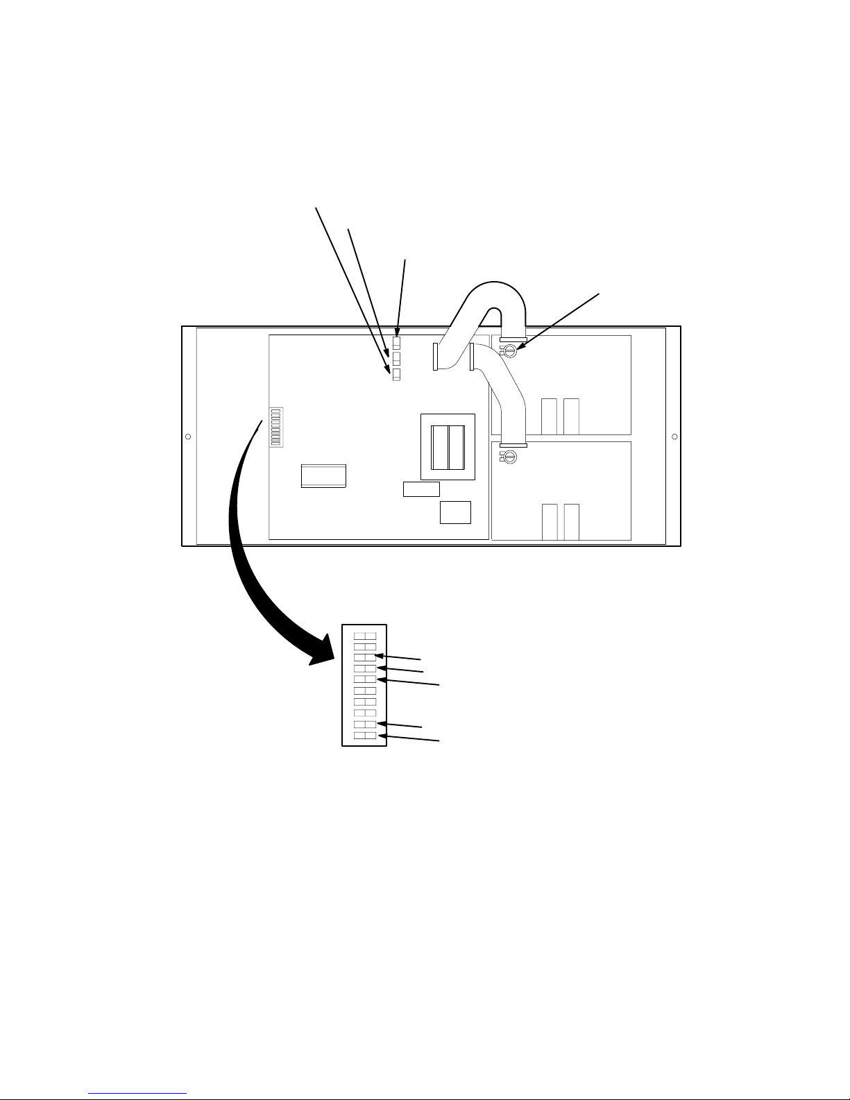
REFRIGERATION COMMON OUTLET TEMPERATURES
NO. 1 AND NO. 2 EVAPORATOR COILS
NO. 2 EVAPORATOR REFRIGERATION
COIL INLET TEMPERATURE
NO. 1 EVAPORATOR REFRIGERATION
COIL INLET TEMPERATURE
RELAY CIRCUIT
BOARD NO. 1
MASTER CIRCUIT
BOARD
RELAY CIRCUIT
BOARD NO. 2
MOTOR CURRENT
ADJUSTMENT
DIP SWITCH
ASS’Y
1
2
3
4
5
6
7
8
9
10
POINT OF SALE MESSAGE DISPLA Y SELECT
}
SEE NOTE
BEATER MOTORS CURRENT READOUT (SEE Note in Table 5)
MOTOR CURRENT SELF
NOT USED
}
APPLICABLE ELECTRIC OR GAS DEFROST (SEE Table 5)
SERVICE USE ONLY
(SEE Table 5)
FIGURE 6. MASTER AND RELAY CIRCUIT BOARD
-CALIBRATION (SEE Table 5)
21 2992
 Loading...