

Page 1
IMI CORNELIUS INC g One Cornelius Place g Anoka, MN 55303
Telephone (800) 238–3600 Facsimile (800) 535–4231
Operator’s Manual
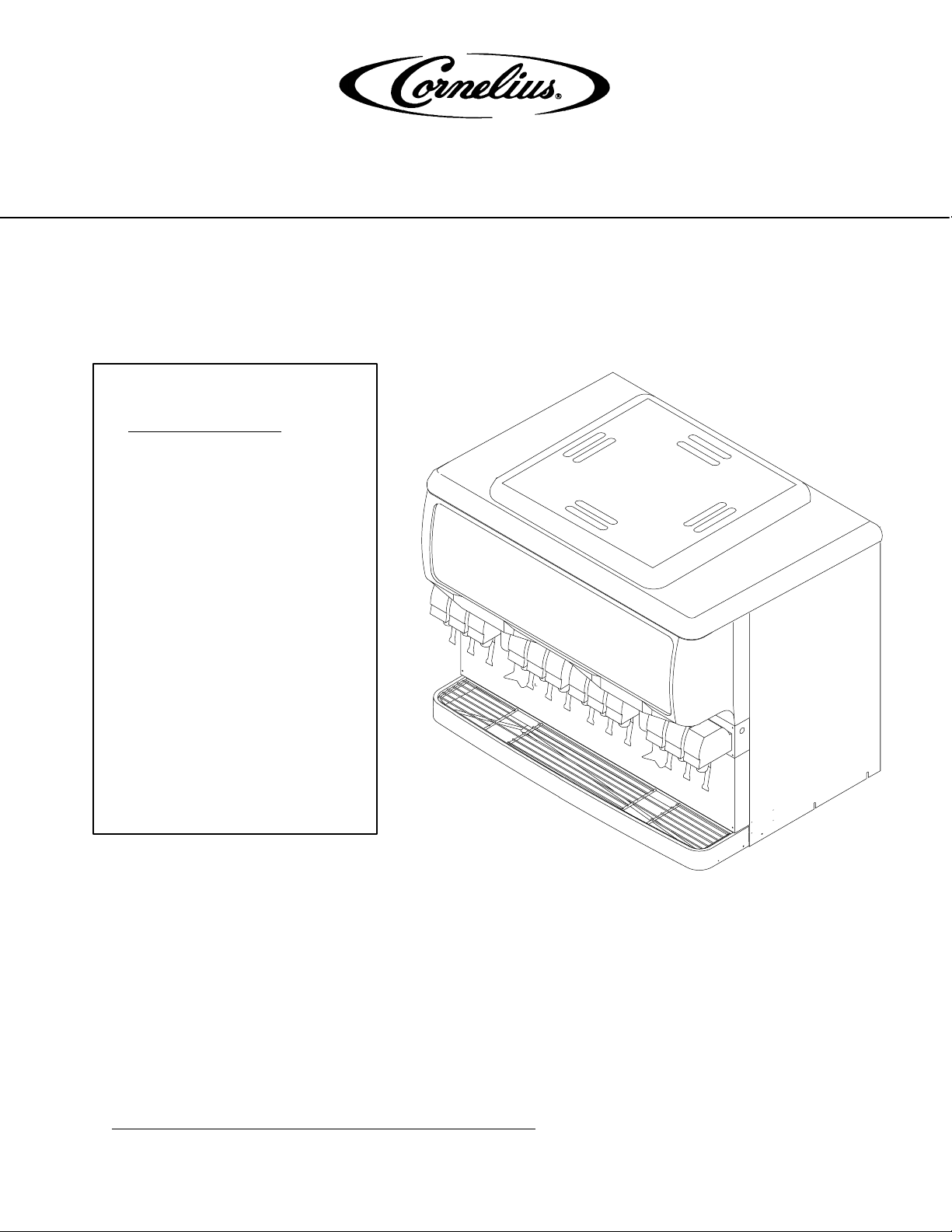
ICE/BEVERAGE DISPENSER
Model: ED 300 BC
IMPORTANT:
TO THE INSTALLER.
It is the responsibility of
the Installer to ensure that
the water supply to the
dispensing equipment is
provided with protection
against backflow by an air
gap as defined in
ANSI/ASME A112.1.2-1979;
or an approved vacuum
breaker or other such
method as proved effective
by test.
Water pipe connections
and fixtures directly
connected to a potable
water supply shall be
sized, installed, and
maintained according to
Federal, State, and Local
Codes.
Part No.92059OPR
March 24, 2004
Revised: N/A
Revision: A
THIS DOCUMENT CONTAINS IMPORTANT INFORMATION
This Manual must be read and understood before installing or operating this equipment
IMI CORNELIUS INC; 2004
PRINTED IN U.S.A
Page 2

TABLE OF CONTENTS
MAINTENANCE 1. . . . . . . . . . . . . . . . . . . . . . . . . . . . . . . . . . . . . . . . . . . . . . . . . . . . . . . . . . .
DAILY 1. . . . . . . . . . . . . . . . . . . . . . . . . . . . . . . . . . . . . . . . . . . . . . . . . . . . . . . . . . . . . . . .
WEEKLY 1. . . . . . . . . . . . . . . . . . . . . . . . . . . . . . . . . . . . . . . . . . . . . . . . . . . . . . . . . . . . . .
MONTHLY 1. . . . . . . . . . . . . . . . . . . . . . . . . . . . . . . . . . . . . . . . . . . . . . . . . . . . . . . . . . . .
START-UP & OPERATING INSTRUCTIONS 1. . . . . . . . . . . . . . . . . . . . . . . . . . . . . .
CLEANING INSTRUCTIONS 1. . . . . . . . . . . . . . . . . . . . . . . . . . . . . . . . . . . . . . . . . . . .
DISPENSER 2. . . . . . . . . . . . . . . . . . . . . . . . . . . . . . . . . . . . . . . . . . . . . . . . . . . . . . . . . .
BEVERAGE SYSTEM IF APPLICABLE 3. . . . . . . . . . . . . . . . . . . . . . . . . . . . . . . . . . . . . .
REMOVAL AND REPLACEMENT OF AGITATORS 5. . . . . . . . . . . . . . . . . . . . . . . . .
TO REMOVE AGITATORS FOR CLEANING 5. . . . . . . . . . . . . . . . . . . . . . . . . . . . .
TROUBLESHOOTING 6. . . . . . . . . . . . . . . . . . . . . . . . . . . . . . . . . . . . . . . . . . . . . . . . . . . . . .
BLOWN FUSE OR CIRCUIT BREAKER. 6. . . . . . . . . . . . . . . . . . . . . . . . . . . . . . . . . .
GATE DOES NOT OPEN. AGITATOR DOES NOT TURN. 6. . . . . . . . . . . . . . . . . .
GATE DOES NOT OPEN OR IS SLUGGISH. AGITATOR TURNS. 6. . . . . . . . . .
ICE DISPENSES CONTINUOUSLY. 6. . . . . . . . . . . . . . . . . . . . . . . . . . . . . . . . . . . . . .
SLUSHY ICE. WATER IN HOPPER. 6. . . . . . . . . . . . . . . . . . . . . . . . . . . . . . . . . . . . .
BEVERAGES DO NOT DISPENSE. 6. . . . . . . . . . . . . . . . . . . . . . . . . . . . . . . . . . . . . .
BEVERAGES TOO SWEET. 6. . . . . . . . . . . . . . . . . . . . . . . . . . . . . . . . . . . . . . . . . . . .
BEVERAGE NOT SWEET ENOUGH. 7. . . . . . . . . . . . . . . . . . . . . . . . . . . . . . . . . . . .
BEVERAGES NOT COLD (UNITS WITH BUILT–IN COLD PLATE). 7. . . . . . . . . .
AGITATORS TURN IN OPPOSITE DIRECTIONS 7. . . . . . . . . . . . . . . . . . . . . . . . . .
ICE DOES NOT DISPENSE FROM ONE GATE ASSEMBLY 7. . . . . . . . . . . . . . . .
FLAVOR SYRUPS DO NOT DISPENSE 7. . . . . . . . . . . . . . . . . . . . . . . . . . . . . . . . . .
FLAVOR DISPENSES FOR MORE THAN 1 SEC 7. . . . . . . . . . . . . . . . . . . . . . . . . .
FLAVOR DISPENSERS MORE THAN .5 OZ 7. . . . . . . . . . . . . . . . . . . . . . . . . . . . . .
WARRANTY 8. . . . . . . . . . . . . . . . . . . . . . . . . . . . . . . . . . . . . . . . . . . . . . . . . . . . . . . . . . . . . .
Page
i
92059OPR
Page 3
MAINTENANCE
The following dispenser maintenance should be performed at the intervals indicated:
DAILY
(or as required)
Remove foreign material from vending area drip tray to prevent drain blockage.
WEEKLY
(or as required)
Clean vending area. Check for proper water drainage from the vending area drip tray.
MONTHLY
Clean and sanitize the hopper interior (see CLEANING INSTRUCTIONS).
START-UP & OPERATING INSTRUCTIONS
Fill the hopper with ice. Dispense several large cups of ice (approximately 20 to 30 seconds total dispensing
time) to allow ice to fill the cold plate cabinet. Add ice to the hopper as necessary to refill and replace the lid. Allow 10 to 15 minutes for the cold plate to cool down. Repeat this procedure whenever the dispenser has run out
of ice. Start up the beverage system and adjust faucets to the proper brix. Contact your local syrup distributor for
complete information on the beverage system.
In normal operation, pushing the ice dispenser mechinism will cause ice to flow from the ice chute. Ice flow will
continue until the dispenser mechinism is released. Dispensing of any faucet will provide beverage of the appropriate flavor.
CAUTION: Use caution to avoid spilling ice when filling dispenser. Immediately clean up any
spilled ice from filling or operating the unit. To prevent contamination of ice, the lid must be
installed on the unit at all times.
If the dispenser fails to dispense ice or beverage see troubleshooting guide.
CLEANING INSTRUCTIONS
WARNING: Disconnect Power Before Cleaning! Do not use metal scrapers, sharp objects or
abrasives on the ice storage hopper, top cover and the agitator disk, as damage may result.
Do not use solvents or other cleaning agents, as they may attack the plastic material.
Soap solution - use a mixture of mild detergent and warm 100 degrees F potable water.
Sanitizing solution
solution to this ratio will create a solution of 200 PPM.
- use 1/2 ounce of household bleach in 1 gallon of potable water. Preparing the sanitizing
1 92059OPR
Page 4
DISPENSER
1. CLEANING EXTERIOR SURFACES
Important: Perform the following daily.
A. Remove the cup rest from drip tray.
B. Wash the drip tray with soap solution. Rinse with clean water and allow solution to run down the drain.
C. Wash cup rest with soap solution and rinse in clean water. Install the cup rest into the drip tray.
D. Clean all exterior surfaces with soap solution and rinse in clean water.
2. COLD PLATE INSPECTION BEFORE CLEANING
A. Remove splash panel.
B. Remove the plastic cold plate cover to expose the cold plate.
C. Locate and remove any debris from the cold plate, drain trough and make certain that the drain holes
are not clogged.
D. Reinstall the cold plate cover.
E. Reinstall the splash panel in the reverse order in which it was removed.
3. CLEANING INTERIOR SURFACES
CAUTION: When pouring liquid into the hopper, do not exceed the rate of 1/2 gallon per
minute.
Important: Perform the following at least once a month.
A. Remove agitator assembly.
B. Using a long handle nylon bristle brush, clean the interior of the hopper, top, cover and cold plate with
soap solution. The cold plate can be reached by going through the ice opening on the hopper bottom.
Make certain to reach the entire surface of the cold plate including the corners. Clean the agitator assembly with soap solution using a nylon brush or a sponge. Thoroughly rinse the hopper, top cover,
agitator and cold plate surfaces with clean potable water.
C. Remove merchandiser and ice chute cover from dispenser.
D. With a nylon bristle brush or sponge, clean the inside of the ice chute, gasket and cover with soap
solution and rinse thoroughly to remove all traces of detergent.
E. Re-assemble agitator assembly. Make certain that o-ring is seated properly in agitator bushing.
F. Using a mechanical spray bottle filled with sanitizing solution, spray the entire interior and agitator as-
sembly. Allow to air dry.
G. Re-assemble ice chute assembly.
H. Using a mechanical spray bottle filled with sanitizing solution, spray the inside of the ice chute. Allow
to air dry.
I. Reinstall merchandiser.
292059OPR
Page 5

BEVERAGE SYSTEM
IF APPLICABLE
WARNING: Disconnect Power Before Cleaning! Do not use metal scrapers, sharp objects or
abrasives on the ice storage hopper, top cover and the agitator disk, as damage may result.
Do not use solvents or other cleaning agents, as they may attack the plastic material.
Soap solution - use a mixture of mild detergent and warm 100 degrees F potable water.
Sanitizing solution
solution to this ratio the required solution of 200 PPM will be obtained.
Cleaning tank
1. DISPENSING VALVES
Refer to addendum supplied with the unit that is applicable to the manufacturer of the valves installed on the
unit.
2. PRODUCT TUBING
Only trained and qualified persons should perform these cleaning and sanitizing procedures.
A. Sanitize tank systems, Post-Mix and Pre-Mix
a. Remove all the quick disconnects from all the tanks. Fill a suitable pail or bucket with soap solu-
b. Submerge all disconnects (gas and liquid) in the soap solution and then clean them using a nylon
c. Prepare sanitizing solution and using a mechanical spray bottle, spray the disconnects. Allow to
d. Using a clean, empty tank, prepare five (5) gallons of the sanitizing solution. Rinse the tank dis-
- use 1/2 ounce of household bleach in 1 gallon of potable water. Preparing the sanitizing
- Fill clean, empty tank with five (5) gallons of warm potable water.
tion.
bristle brush. (Do not use a wire brush). Rinse with clean water.
air dry.
connects with approximately 9 oz. of the
sanitizing solution. Close the tank.
e. Prepare cleaning tank by filling clean five (5) gallon tank with warm 100 degrees F potable
water.
f. Connect a gas disconnect to the tank and then apply one of the product tubes to the cleaning
tank. Operate the appropriate valve until liquid dispensed is free of any syrup.
g. Disconnect cleaning tank and hook up sanitizing tank to syrup line and CO
h. Energize beverage faucet until chlorine sanitizing solution is dispensed through the faucet. Flush
at least two (2) cups of liquid to insure that the sanitizing solution has filled the entire length of the
syrup tubing.
i. Allow sanitizer to remain in lines for fifteen (15) minutes.
j. Repeat the step above, applying a different product tube each time until all tubes are filled with
the sanitizing solution.
k. For post-mix valves, remove the nozzle and syrup diffuser and clean them in a mild soap solution.
Rinse with clean water and reassemble the nozzle and syrup diffuser to the valve.
l. Discard the tank of sanitizing solution and reconnect the syrup tanks. Operate the valves until all
sanitizer has been flushed from the system and only syrup is flowing.
3 92059OPR
system.
2
Page 6

B. Sanitize syrup lines, B-I-B Systems
a. Remove all the quick disconnects from all the B-I-B containers.
b. Fill a suitable pail or bucket with soap solution.
c. Submerge all disconnects (gas and liquid) in the soap solution and then clean them using a nylon
bristle brush. (Do not use a wire brush). Rinse with clean water.
d. Using a plastic pail, prepare approximately five (5) gallons of sanitizing solution.
e. Rinse the B-I-B disconnects in the sanitizing solution.
f. Sanitizing fittings must be attached to each B-I-B disconnect. If these fittings are not available,
the fittings from empty B-I-B bags can be cut from the bags and used. These fittings open the
disconnect so the sanitizing solution can be drawn through the disconnect.
g. Place all the B-I-B disconnects into the pail of sanitizing solution. Operate all the valves until the
sanitizing solution is flowing from the valve. Allow sanitizer to remain in lines for fifteen (15) minutes.
h. Remove the nozzle and syrup diffuser from each valve and clean them in a soap solution. Rinse
with clean water and reassemble the nozzle and syrup diffuser to the valve.
i. Remove the sanitizing fittings from the B-I-B disconnects and connect the disconnects to the ap-
propriate B-I-B container. Operate the valves until all sanitizer has been flushed from the system
and syrup is flowing freely.
C. Sanitize Flavor syrup lines, B–I–B System
a. Remove all the quick disconnects from all the B–I–B containers.
b. Fill a suitable pail or bucket with soap solution.
c. Submerge all disconnects (gas and liquid) in the soap solution and then clean them using a nylon
bristle brush. (Do not use a wire brush). Rinse with clean water.
d. Using a plastic pail, prepare approximately five (5) gallons of sanitizing solution.
e. Rinse the B–I–B disconnects in the sanitizing solution.
f. Sanitizing fittings must be attached to each B–I–B disconnect. If these fittings are not available,
the fittings from the empty B–I–B bags can be cut from the bags and used. These fittings open
the disconnect so the sanitizing solution can be drawn through the disconnect.
g. Place all the B–I–B disconnects into the pail of sanitizing solution. ‘Purge’ all the flavor valves
until the sanitizing solution is flowing from inner nozzle. This can easily be accomplished by
holding down each keypad button for at least 15 seconds. After 15 seconds the valve will go into
‘purge’ mode and continuously dispense for the next 60 seconds. Allow sanitizer to remain in
lines for at least thirty (30) minutes.
h. Remove nozzle cover (outer nozzle) from flavor module housing. Clean in a soap solution and
rinse with clean water.
i. Remove the sanitizing fittings from the B–I–B disconnects and connect the disconnects to the ap-
propriate B–I–B container. Operate the flavor valves until all sanitizer has been flushed from the
system and flavor syrup is flowing freely.
492059OPR
Page 7

REMOVAL AND REPLACEMENT OF AGITATORS
LEFT HAND
AGITATOR
O–RING
COUNTER CLOCKWISE
ROTATION ROTATION
RIGHT HAND AGITATOR
WITH HOLE IN UPRIGHT
CLOCKWISE
FRONT (VALVE SIDE) VIEW FROM TOP OF DISPENSER
To Remove Agitators For Cleaning
1. Lift agitator and disc from unit..
2. Remove O-Ring starting at notch. Warm the O-Ring with water to ease removal.
3. Lift the plastic agitator disc off of the stainless-steel agitator.
4. Replace by reversing steps.
Note: Refer to Sanitize Procedure in the Owners Instruction for complete cleaning and sanitizing
instructions.
5 92059OPR
Page 8

TROUBLESHOOTING
IMPORTANT: Only qualified personnel should service internal components or electrical wiring.
WARNING: If repairs are to be made to a product system, remove quick disconnects from
the applicable product tank, then relieve the system pressure before proceeding. If repairs
are to be made to the CO
system, stop dispensing, shut off the CO
2
system pressure before proceeding. If repairs are to be made to the refrigeration system, make sure
electrical power is disconnected from the unit.
Should your unit fail to operate properly, check that there is power to the unit and that the hopper contains ice. If the unit does not dispense, check the following chart under the appropriate symptoms to aid
in locating the defect.
supply, then relieve the
2
Trouble
Probable Cause
BLOWN FUSE OR CIRCUIT BREAKER. A. Short circuit in wiring.
B. Defective gate solenoid.
C. Defective agitator motor.
D. Defective gate rectifier
GATE DOES NOT OPEN. AGITATOR DOES NOT
A. No power.
TURN.
B. Bent depressor plate (does not actuate switch).
C. Defective dispensing switch.
GATE DOES NOT OPEN OR IS SLUGGISH.
A. Defective gate solenoid.
AGITATOR TURNS.
B. Excessive pressure against gate slide.
C. Defective Rectifier.
ICE DISPENSES CONTINUOUSLY.
A. Stuck or bent depressor plate (does not
release switch).
B. Defective dispensing switch.
C. Improper switch installation.
SLUSHY ICE. WATER IN HOPPER.
BEVERAGES DO NOT DISPENSE.
BEVERAGES TOO SWEET.
A. Blocked drain.
B. Unit not level.
C. Poor ice quality due to water quality or
icemaker problems.
D. Improper use of flaked ice.
A. No 24 volt power to faucets.
B. No CO
pressure.
2
A. Carbonator not working.
B. No CO
pressure in carbonator.
2
C. Faucet brix requires adjusting.
692059OPR
Page 9

Trouble Probable Cause
BEVERAGE NOT SWEET ENOUGH.
A. Empty syrup tank.
B. Faucet brix requires adjusting.
BEVERAGES NOT COLD (UNITS WITH BUILT–IN
COLD PLATE).
A. Unit standing with no ice in hopper – no ice in
cold plate cabinet.
AGITATORS TURN IN OPPOSITE DIRECTIONS A. This is normal and is necessary for uniform ice
agitation.
ICE DOES NOT DISPENSE FROM ONE GATE
A. Agitators reversed
ASSEMBLY
B. Defective gate solenoid or rectifier
C. Motors wired incorrectly
FLAVOR SYRUPS DO NOT DISPENSE A. No 24 volt power to PC board.
B. No CO2 pressure.
C. Empty syrup tank.
D. Kinked tubing.
E. Clogged inner nozzle.
F. Defective PC board.
G. Defective harness from keypad.
H. Defective Flow control.
I. Defective solenoid harness.
J. Defective keypad.
FLAVOR DISPENSES FOR MORE THAN 1 SEC A. Dip switch settings on control board incorrect.
B. PC board defective.
C. Defective flow control.
FLAVOR DISPENSES MORE THAN .5 OZ A. Dip switch settings on control board incorrect.
B. Flow control incorrectly set.
C. PC board defective.
D. Defective flow control.
Contact your local syrup or beverage equipment distributor for additional information and troubleshooting of beverage system.
7 92059OPR
Page 10

Page 11

WARRANTY
IMI Cornelius Inc. warrants that all equipment and parts are free from defects in material and workmanship under normal use and service. For a copy of the warranty applicable to your Cornelius product, in your country, please write, fax or telephone the IMI Cornelius office nearest you. Please
provide the equipment model number, serial number and the date of purchase.
IMI Cornelius Offices
AUSTRALIA D P. O. 210, D RIVERWOOD, D NSW 2210, AUSTRALIA D (61) 2 533 3122 D FAX (61) 2 534 2166
D AM LANGEN FELDE 32 D A-1222 D VIENNA, AUSTRIA D (43) 1 233 520 D FAX (43) 1-2335-2930
AUSTRIA
D BOSKAPELLEI 122 D B-2930 BRAASCHAAT, BELGIUM D (32) 3 664 0552 D FAX (32) 3 665 2307
BELGIUM
D RUA ITAOCARA 97 D TOMAS COELHO D RIO DE JANEIRO, BRAZIL D (55) 21 591 7150 D FAX (55) 21 593 1829
BRAZIL
ENGLAND
D TYTHING ROAD ALCESTER D WARWICKSHIRE, B49 6 EU, ENGLAND D (44) 789 763 101 D FAX (44) 789 763 644
D 71 ROUTE DE ST. DENIS D F-95170 DEUIL LA BARRE D PARI S, FRANCE D (33) 1 34 28 6200 D FAX (33) 1 34 28 6201
FRANCE
D CARL LEVERKUS STRASSE 15 D D-4018 LANGENFELD, GERMANY D (49) 2173 7930 D FAX (49) 2173 77 438
GERMANY
D 488 MESSOGION AVENUE D AGIA PARA SK EV I D 153 42 D ATHENS, GR EECE D (30) 1 600 1073 D FAX (30) 1 601 2491
GREECE
KONG D 1104 TAIKOTSUI CENTRE D 11-15 KOK CHEUNG ST D TAIKOKTSUE, HONG KONG D (852) 789 9882 D FAX (852) 391 6222
HONG
D VIA PELLIZZARI 11 D 1-20059 D VIMARCATE, ITALY D (39) 39 608 0817 D FAX (39) 39 608 0814
ITALY
ZEALAND D 20 LANSFORD CRES. D P. O. BOX 19-044 AVONDALE D AUCKLAND 7, NEW ZEALAND D (64) 9 8200 357 D FAX (64) 9 8200 361
NEW
SINGAPORE
SPAIN
USA
D 16 TUAS STREET D SINGAPORE 2263 D (65) 862 5542 D FAX (65) 862 5604
D POLIGONO INDUSTRAIL D RIERA DEL FONOLLAR D E-08830 SANT BOI DE LLOBREGAT D BARCELONA, SPAIN D (34) 3 640 2839 D FAX (34) 3 654 3379
D ONE CORNELIUS PLACE D ANOKA, MINNESOTA D (612) 421-6120 D FAX (612) 422-3255
LD004
4/21/98
892059OPR
Page 12

IMI CORNELIUS INC.
CORPORATE HEADQUARTERS:
One Cornelius Place
Anoka, Minnesota 55303-6234
(763) 421-6120
(800) 238-3600
9 92059OPR
Page 13

 Loading...