

Cornelius DPP 230, DPC 230, DPK 230, DPT 230 Installation & Service Manual
ICE DISPENSER
Installation/Service
Manual
Distributed By:
Commercial Refrigeration Service, Inc.
WWW.IceCubes.NET
WWW.CorneliusParts.COM
(866) 423-6253
DPP 230-Push-Button Operated
DPK 230-Key Operated (Optional)
DPC 230-Card Operated (Optional)
DPT 230-Token Operated (Optional)
(623) 869-8881
Part No. 161952801
January, 1995
Revised 9/11/97
THIS DOCUMENT CONTAINS IMPORTANT INFORMATION
This Manual must be read and understood before installing or operating this equipment
IMI CORNELIUS INC; 1995
PRINTED IN U.S.A

TABLE OF CONTENTS
SAFETY INFORMATION 1. . . . . . . . . . . . . . . . . . . . . . . . . . . . . . . . . . . . . . . . . . . . . . . . . . .
RECOGNIZE SAFETY INFORMATION 1. . . . . . . . . . . . . . . . . . . . . . . . . . . . . . .
UNDERSTAND SIGNAL WORDS 1. . . . . . . . . . . . . . . . . . . . . . . . . . . . . . . . . . .
FOLLOW SAFETY INSTRUCTIONS 1. . . . . . . . . . . . . . . . . . . . . . . . . . . . . . . . .
INTRODUCTION 3. . . . . . . . . . . . . . . . . . . . . . . . . . . . . . . . . . . . . . . . . . . . . . . . . . . . . . . . . . .
SERVICE CORRESPONDENCE 3. . . . . . . . . . . . . . . . . . . . . . . . . . . . . . . . . . . . . . . .
GENERAL INFORMATION 5. . . . . . . . . . . . . . . . . . . . . . . . . . . . . . . . . . . . . . . . . . . . . . . . . .
TO THE USER OF THIS MANUAL 5. . . . . . . . . . . . . . . . . . . . . . . . . . . . . . . . . . . . . . .
CLAIMS INSTRUCTIONS 5. . . . . . . . . . . . . . . . . . . . . . . . . . . . . . . . . . . . . . . . . . . . .
WARRANTY REFERENCE INFORMATION 5. . . . . . . . . . . . . . . . . . . . . . . . . . . . . . .
DESIGN DATA 5. . . . . . . . . . . . . . . . . . . . . . . . . . . . . . . . . . . . . . . . . . . . . . . . . . . . . . . .
INSTALLATION 7. . . . . . . . . . . . . . . . . . . . . . . . . . . . . . . . . . . . . . . . . . . . . . . . . . . . . . . . . . .
SELECTING LOCATION 7. . . . . . . . . . . . . . . . . . . . . . . . . . . . . . . . . . . . . . . . . . . . . . . .
ELECTRICAL REQUIREMENTS 7. . . . . . . . . . . . . . . . . . . . . . . . . . . . . . . . . . . . . . . . .
INSTALLATION 7. . . . . . . . . . . . . . . . . . . . . . . . . . . . . . . . . . . . . . . . . . . . . . . . . . . . . . . .
INSTALLING ICE DISPENSER 7. . . . . . . . . . . . . . . . . . . . . . . . . . . . . . . . . . . . . .
FILLING DISPENSER ICE BIN HOPPER WITH ICE 8. . . . . . . . . . . . . . . . . . .
ADJUSTMENTS 8. . . . . . . . . . . . . . . . . . . . . . . . . . . . . . . . . . . . . . . . . . . . . . . . . . .
OPERATION 10. . . . . . . . . . . . . . . . . . . . . . . . . . . . . . . . . . . . . . . . . . . . . . . . . . . . . .
MAINTENANCE 13. . . . . . . . . . . . . . . . . . . . . . . . . . . . . . . . . . . . . . . . . . . . . . . . . . . . . . . . . . .
Page
CLEANING AND SANITIZING 13. . . . . . . . . . . . . . . . . . . . . . . . . . . . . . . . . . . . . . . . . . .
DAILY CLEANING (SEE FIGURE 2) 13. . . . . . . . . . . . . . . . . . . . . . . . . . . . . . . . .
CLEANING AND SANITIZING ICE BIN INTERIOR 13. . . . . . . . . . . . . . . . . . . . .
ADJUSTMENTS 14. . . . . . . . . . . . . . . . . . . . . . . . . . . . . . . . . . . . . . . . . . . . . . . . . . . . . . .
FILLING DISPENSER ICE BIN HOPPER 14. . . . . . . . . . . . . . . . . . . . . . . . . . . . . . . . .
TROUBLESHOOTING 17. . . . . . . . . . . . . . . . . . . . . . . . . . . . . . . . . . . . . . . . . . . . . . . . . . . . .
NO ICE DISPENSED 17. . . . . . . . . . . . . . . . . . . . . . . . . . . . . . . . . . . . . . . . . . . . . .
WARRANTY 24. . . . . . . . . . . . . . . . . . . . . . . . . . . . . . . . . . . . . . . . . . . . . . . . . . . . . . . . . . . . . .
LIST OF FIGURES
FIGURE 1. DIMENSIONS/DRAIN CONNECTIONS 6. . . . . . . . . . . . . . . . . . . . . . . .
FIGURE 2. DISPENSER COMPONENTS (PUSH-BUTTON MODEL SHOWN) 9.
FIGURE 3. WIRING DIAGRAM 15. . . . . . . . . . . . . . . . . . . . . . . . . . . . . . . . . . . . . . . . . .
FIGURE 4. ICE DISPENSER 19. . . . . . . . . . . . . . . . . . . . . . . . . . . . . . . . . . . . . . . . . . . .
FIGURE 5. ELECTRICAL BOX ASS’Y 22. . . . . . . . . . . . . . . . . . . . . . . . . . . . . . . . . . . .
LIST OF TABLES
TABLE 1. DESIGN DATA 5. . . . . . . . . . . . . . . . . . . . . . . . . . . . . . . . . . . . . . . . . . . . . . .
i 161952801
SAFETY INFORMATION
Recognize Safety Information
This is the safety-alert symbol. When you see this
symbol on our machine or in this manual, be alert to
the possibility of personal injury.
Follow recommended precautions and safe operating
practices.
Understand Signal Words
A signal word - DANGER, WARNING, OR CAUTION
is used with the safety-alert symbol. DANGER identifies the most serious hazards.
DANGER
Safety signs with signal word DANGER or WARNING
are typically near specific hazards.
General precautions are listed on CAUTION safety
signs. CAUTION also calls attention to safety messages in this manual.
Follow Safety Instructions
Carefully read all safety messages in this manual and on your machine safety signs. Keep safety signs in
good condition. Replace missing or damaged safety signs. Learn how to operate the machine and how to
use the controls properly. Do not let anyone operate the machine without instructions. Keep your machine in
proper working condition. Unauthorized modifications to the machine may impair function and/or safety and
affect the machine life.
WARNING
CAUTION
1 161952801

THIS PAGE LEFT BLANK INTENTIONALLY
2161952801

INTRODUCTION
SERVICE CORRESPONDENCE
We have strived to produce a quality product. The design has been kept simple thus insuring trouble free operation.
This manual has been prepared to assist the Service Person and Users with information concerning installation,
construction, and maintenance of the Ice Dispenser. The problems of the Service Person and the User have
been given special attention in the development and engineering of our Ice Dispensers.
If you encounter a problem which is not covered in this manual, please feel free to write or call. We will be
happy to assist you in any way we can.
When writing, please state the model and the serial number of your Ice Dispenser.
Address all correspondence in regard to your Ice Dispenser to:
IMI CORNELIUS INC
A PRODUCT OF IMI CORNELIUS INC.
ONE CORNELIUS PLACE
ANOKA, MN 55303-6234
PHONE 800-554-3526
FAX 612-422-3232
(PRINTED IN USA)
3 161952801

THIS PAGE LEFT BLANK INTENTIONALLY
161952801
4

GENERAL INFORMATION
TO THE USER OF THIS MANUAL
This Manual is a guide for installing and operating this equipment. Refer to Table of Contents for page location
of detailed information pertaining to questions that may arise during installation or operation of this equipment.
CLAIMS INSTRUCTIONS
Claims: In the event of shortage, notify the carrier as well as IMI Cornelius immediately. In the event of dam-
age, notify the carrier. IMI Cornelius is not responsible for damage occurring in transit, but will gladly
render assistance necessary to pursue your claim. Merchandise must be inspected for concealed damage within 15 days of receipt.
WARRANTY REFERENCE INFORMATION
Warranty Registration Date
(to be filled out by customer)
Unit Part Number:
Serial Number:
Install Date:
Local Authorized
Service Center:
DESIGN DATA
Table 1. Design Data
Unit Model Numbers:
DPP 230 Push-Button Operated
DPK 230 Key-Operated (Optional), 161467-001
DPC 230 Card Operated (Optional), 161467-002
DPT 230 Token Operated (Optional), 1614671–000
Overall Dimensions:
Height 59-3/8 inches
Width 30 inches
Depth 30 inches
Weights:
Dry Weight (No ice in ice bin Bin) 170 pounds
Shipping Weight 200 pounds
Capacity:
Ice Bin Capacity 160 pounds
5 161952801
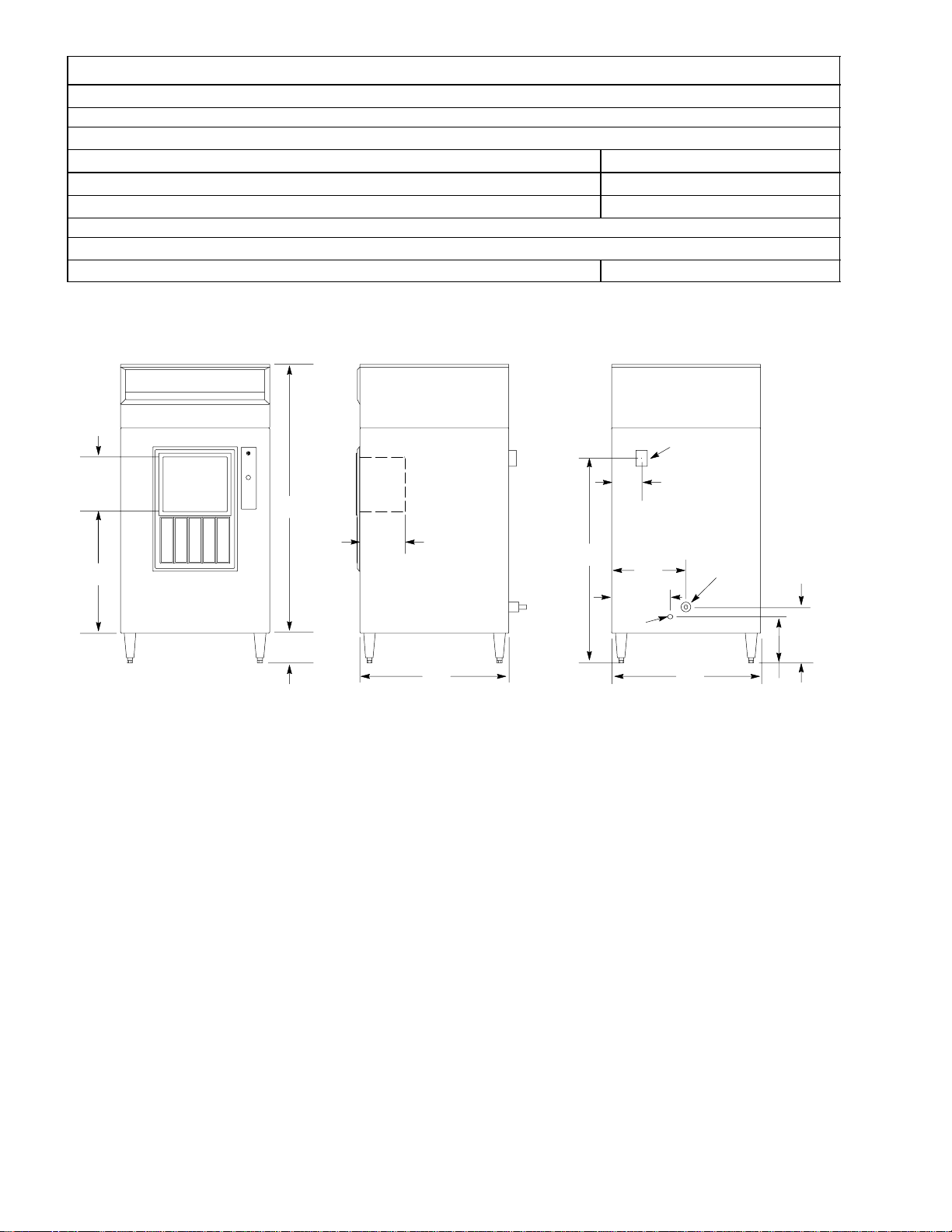
Table 1. Design Data (cont’d)
Ambient Operating Temperature 40° F to 100° F
Electrical:
Average Current Draw 2.5 Amps
Time Delay Fuse Rating 15 Amps
Power Supply (Single Phase) 120 VAC, 60 H
Plumbing Connections:
Bin Drain 1-inch O.D. Vinyl Tube
C
Z
11.06
54
9
24
6
FRONT VIEW SIDE VIEW REAR VIEW
A CONDENSATE DRAIN 1/2 F.P.T.
B BIN AND STATION DRAIN 1 IN. VINYL TUBE
C ELECTRICAL JUNCTION BOX
NOTE: REMOVABLE TOP OF UNIT CUT FOR MOUNTING
CORNELIUS 30” WIDE VERTICAL EVAPORATOR CUBER.
30
41.13
5
12
A
15
B
11.25
30
9.56
FIGURE 1. DIMENSIONS/DRAIN CONNECTIONS
6161952801

INSTALLATION
This section of the manual covers installing the dispenser, preparing the dispenser for operation, and operating
the dispenser.
SELECTING LOCATION
1. Locate the Ice Dispenser in a cool shaded area close to a properly grounded and fused electrical outlet
with proper electrical requirements (see Table 1 Design Data).
2. Provide a suitable trapped open drain as close as possible to the area where the Ice Dispenser will be
installed. This may be an existing floor drain or a 1 1/4-inch trapped open drain. All plumbing must be
installed according to National and local plumbing codes.
ELECTRICAL REQUIREMENTS
The electrical supply must be 120V 60 cycle, 1 phase and the unit must be properly grounded. ALL WIRING
MUST CONFORM TO NATIONAL AND LOCAL ELECTRICAL CODES. VOLTAGE MINIMUMS: 120V unit –
103 volts minimum. REFER TO SERIAL PLATE FOR MINIMUM CIRCUIT AMPACITY AND MAXIMUM TIME
DELAY FUSE SIZE.
INSTALLATION
INSTALLING ICE DISPENSER
1. To uncrate the Ice Dispenser, carefully remove the staples holding the crate to the bottom of the skid, then
lift the crate up off the Dispenser.
2. Very carefully tip the Ice Dispenser over on it’s side and remove the four bolts holding the skid to the bot-
tom of the Dispenser, then remove the skid.
NOTE: The leg kit, loose-shipped and found inside the Ice Dispenser, must be installed at this time.
3. Install the four legs in four corners of the Ice Dispenser base as shown in Figure 2.
4. Very carefully set the Ice Dispenser in upright position on it’s legs in selected operating location. Make sure
the Ice Dispenser is leveled after placing in operating location.
5. Locate the ice storage bin drain hose (3/4-inch hose) located on back side of the Ice Dispenser
(see figure 1) and route it to to the open drain. The storage bin drains by gravity and the drain hose must
maintain a gradual slope to the drain for proper draining. The drain hose should be insulated to prevent
condensation from dripping from the hose. Condensation dripping from the drain hoses can cause serious
staining of carpeting or hardwood floors.
6. A separate drain line must be provided for the condensate drain (see figure 1). The parts bag inside the Ice
Dispenser contains a plastic 1/2- inch NPT to a 3/4-inch O.D. drain hose fitting that may be used to make
the condensate drain hose connection to the Ice Dispenser..
NOTE: Plumbing codes will not allow the ice storage bin drain hose and the condensate drain hose to
be tied together which could possibly cause water from the ice bin drain hose to “back up” into the
condensate drain hose.
7. Using the condensate drain hose fitting referred to in preceding step 6, Install the fitting in the Ice
Dispenser.
1619528017
 Loading...