

Page 1
®
VISUAL MERCHANDISERS
COR7VM, COR12VM, COR17VM, COR23VM,
COR35VMSD, COR45VMSD, COR49VMD, COR67VMST
Service Manual
Release Date: May 24, 2005
Publication Number: 630460243SER
Revision Date: NA
Revision: A
Visit the IMI Cornelius web site at www.cornelius.com
for all your Literature needs.
Page 2

SERVICE MANUAL
The products, technical information, and instructions contained in this manual are subject
to change without notice. These instructions are not intended to cover all details or variations of the equipment, nor to provide for every possible contingency in the installation,
operation or maintenance of this equipment. This manual assumes that the person(s)
working on the equipment have been trained and are skilled in working with electrical,
plumbing, pneumatic, and mechanical equipment. It is assumed that appropriate safety
precautions are taken and that all local safety and construction requirements are being
met, in addition to the information contained in this manual.
To inquire about current revisions of this and other documentation or for assistance with
any Cornelius product contact:
www.cornelius.com
800-238-3600
Trademarks and copyrights:
Aurora, Cornelius, Decade, Hydro Boost, Sitco, Spirit, UF-1, Vanguard, Venture, Olympus, and Vista are registered trademarks of IMI Cornelius Inc.
Optifill trademark is pending.
This document contains proprietary information and it may not be
reproduced in any way without permission from Cornelius.
Printed in U.S.A.
Copyright © 2005, All Rights Reserved, IMI Cornelius, Inc.
Page 3

Visual Merchandiser Service Manual
TABLE OF CONTENTS
Features of the Unit . . . . . . . . . . . . . . . . . . . . . . . . . . . . . . . . . . . . . . . . . . . . . . . . . . 1
Cleaning and Preventive Maintenance . . . . . . . . . . . . . . . . . . . . . . . . . . . . . . . . . . . 1
Fluorescent Lamp and Ballast Replacement . . . . . . . . . . . . . . . . . . . . . . . . . . . . . . 2
To remove the motor cover . . . . . . . . . . . . . . . . . . . . . . . . . . . . . . . . . . . . . . . . . 2
Ballast Replacement . . . . . . . . . . . . . . . . . . . . . . . . . . . . . . . . . . . . . . . . . . . . . . . . . 3
Required tool . . . . . . . . . . . . . . . . . . . . . . . . . . . . . . . . . . . . . . . . . . . . . . . . . . . . 3
To remove the ballast . . . . . . . . . . . . . . . . . . . . . . . . . . . . . . . . . . . . . . . . . . . . . 3
To replace the fluorescent lamp . . . . . . . . . . . . . . . . . . . . . . . . . . . . . . . . . . . . . 4
Temperature Control Replacement . . . . . . . . . . . . . . . . . . . . . . . . . . . . . . . . . . . . . . 6
Required tool . . . . . . . . . . . . . . . . . . . . . . . . . . . . . . . . . . . . . . . . . . . . . . . . . . . . 6
To remove the temperature control . . . . . . . . . . . . . . . . . . . . . . . . . . . . . . . . . . . 6
Evaporator Fan Motor Replacement . . . . . . . . . . . . . . . . . . . . . . . . . . . . . . . . . . . . . 9
Required tools . . . . . . . . . . . . . . . . . . . . . . . . . . . . . . . . . . . . . . . . . . . . . . . . . . . 9
To disconnect the evaporator fan motor electrical terminals . . . . . . . . . . . . . . . 10
To remove the evaporator fan motor . . . . . . . . . . . . . . . . . . . . . . . . . . . . . . . . . 11
Condensing Unit Fan Motor Replacement . . . . . . . . . . . . . . . . . . . . . . . . . . . . . . . 13
Required tools . . . . . . . . . . . . . . . . . . . . . . . . . . . . . . . . . . . . . . . . . . . . . . . . . . 13
To remove the motor cover . . . . . . . . . . . . . . . . . . . . . . . . . . . . . . . . . . . . . . . . 13
To pull out the condensing unit . . . . . . . . . . . . . . . . . . . . . . . . . . . . . . . . . . . . . 14
To replace the condensing unit fan motor . . . . . . . . . . . . . . . . . . . . . . . . . . . . . 15
Starting Relay, Overload Protector, and Start Capacitor Replacement . . . . . . . . . 17
Required tool . . . . . . . . . . . . . . . . . . . . . . . . . . . . . . . . . . . . . . . . . . . . . . . . . . . 17
To remove the motor cover . . . . . . . . . . . . . . . . . . . . . . . . . . . . . . . . . . . . . . . . 17
To pull out the condensing unit . . . . . . . . . . . . . . . . . . . . . . . . . . . . . . . . . . . . . 18
To remove the electrical box . . . . . . . . . . . . . . . . . . . . . . . . . . . . . . . . . . . . . . . 20
To replace the relay . . . . . . . . . . . . . . . . . . . . . . . . . . . . . . . . . . . . . . . . . . . . . 21
To replace the overload protector . . . . . . . . . . . . . . . . . . . . . . . . . . . . . . . . . . . 22
To replace the starting capacitor . . . . . . . . . . . . . . . . . . . . . . . . . . . . . . . . . . . . 22
To install the electrical box . . . . . . . . . . . . . . . . . . . . . . . . . . . . . . . . . . . . . . . . 23
Door and Spring Hinge System . . . . . . . . . . . . . . . . . . . . . . . . . . . . . . . . . . . . . . . . 25
Required tools . . . . . . . . . . . . . . . . . . . . . . . . . . . . . . . . . . . . . . . . . . . . . . . . . . 25
To remove the motor cover . . . . . . . . . . . . . . . . . . . . . . . . . . . . . . . . . . . . . . . . 25
To remove the door . . . . . . . . . . . . . . . . . . . . . . . . . . . . . . . . . . . . . . . . . . . . . . 26
To install the door . . . . . . . . . . . . . . . . . . . . . . . . . . . . . . . . . . . . . . . . . . . . . . . 29
To assemble spring hinge components . . . . . . . . . . . . . . . . . . . . . . . . . . . . . . 34
Glass Door Pane Replacement . . . . . . . . . . . . . . . . . . . . . . . . . . . . . . . . . . . . . . . . 39
To remove the motor cover and door . . . . . . . . . . . . . . . . . . . . . . . . . . . . . . . . 39
Required tools . . . . . . . . . . . . . . . . . . . . . . . . . . . . . . . . . . . . . . . . . . . . . . . . . . 39
To remove the glass door pane . . . . . . . . . . . . . . . . . . . . . . . . . . . . . . . . . . . . 39
To install the door . . . . . . . . . . . . . . . . . . . . . . . . . . . . . . . . . . . . . . . . . . . . . . . 42
Refrigeration System . . . . . . . . . . . . . . . . . . . . . . . . . . . . . . . . . . . . . . . . . . . . . . . . 42
Compressor . . . . . . . . . . . . . . . . . . . . . . . . . . . . . . . . . . . . . . . . . . . . . . . . . . . . 42
Starter relay . . . . . . . . . . . . . . . . . . . . . . . . . . . . . . . . . . . . . . . . . . . . . . . . . . . . 42
© 2005, IMI Cornelius Inc. - i - Publication Number: 630460243SER
Page 4

Visual Merchandiser Service Manual
Thermal protector . . . . . . . . . . . . . . . . . . . . . . . . . . . . . . . . . . . . . . . . . . . . . . . 42
Condenser . . . . . . . . . . . . . . . . . . . . . . . . . . . . . . . . . . . . . . . . . . . . . . . . . . . . . 42
Condenser fan motor . . . . . . . . . . . . . . . . . . . . . . . . . . . . . . . . . . . . . . . . . . . . 43
Evaporator . . . . . . . . . . . . . . . . . . . . . . . . . . . . . . . . . . . . . . . . . . . . . . . . . . . . . 43
Evaporator fan motor . . . . . . . . . . . . . . . . . . . . . . . . . . . . . . . . . . . . . . . . . . . . 43
Capillary tube . . . . . . . . . . . . . . . . . . . . . . . . . . . . . . . . . . . . . . . . . . . . . . . . . . 43
Drier . . . . . . . . . . . . . . . . . . . . . . . . . . . . . . . . . . . . . . . . . . . . . . . . . . . . . . . . . 43
Accumulator . . . . . . . . . . . . . . . . . . . . . . . . . . . . . . . . . . . . . . . . . . . . . . . . . . . 43
Temperature control . . . . . . . . . . . . . . . . . . . . . . . . . . . . . . . . . . . . . . . . . . . . . 43
Cooling cabinet . . . . . . . . . . . . . . . . . . . . . . . . . . . . . . . . . . . . . . . . . . . . . . . . . 44
The Refrigeration Cycle . . . . . . . . . . . . . . . . . . . . . . . . . . . . . . . . . . . . . . . . . . . . . 44
Wiring Diagram 115 V/60 Hz/1 Phase . . . . . . . . . . . . . . . . . . . . . . . . . . . . . . . . . . 45
Troubleshooting . . . . . . . . . . . . . . . . . . . . . . . . . . . . . . . . . . . . . . . . . . . . . . . . . . . 46
Possible causes and solutions . . . . . . . . . . . . . . . . . . . . . . . . . . . . . . . . . . . . . 46
Publication Number: 630460243SER - ii - © 2005, IMI Cornelius Inc.
Page 5
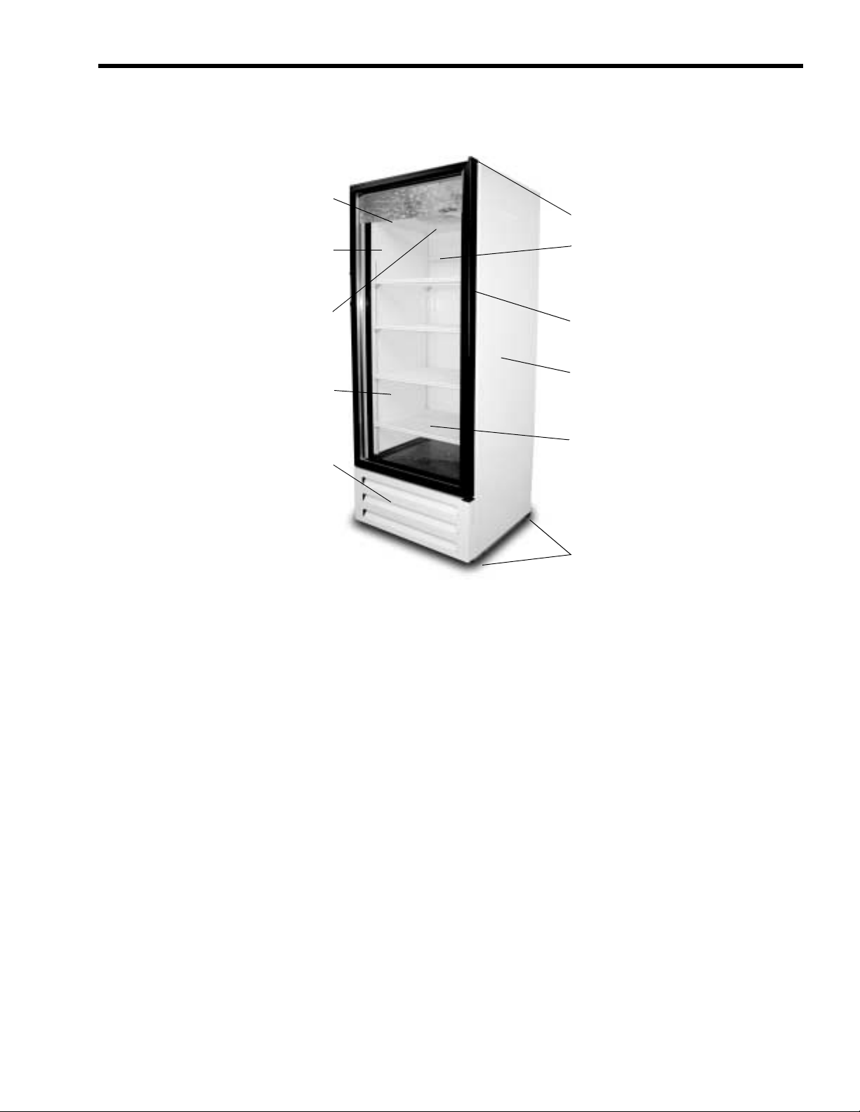
FEATURES OF THE UNIT
Fluorescent interior light
Visual Merchandiser Service Manual
Heavy duty hinges
Strong body with 1 3/4”
thick walls, injected with
CFC-free polyurethane
foam
Forced-air evaporator
for quick temperature
pull down
NSF compliant
interior cabinet
Heavy duty R-134a
condensing unit with zero
maintenance condenser
Double-pane low-e glass
door for high ambient
conditions
Durable PVC frame
Exterior cabinet made of
galvanized, pre-painted
steel, with baked polyester
paint
Reinforced heavy-duty
shelves
Reinforced, 16-gauge,
galvanized steel base
FIGURE 1
CLEANING AND PREVENTIVE MAINTENANCE
Weekly or sooner, as required:
1. Disconnect the power source before cleaning. Remove all products and place in a proper cooler.
2. Clean the interior and exterior with a mild soap or detergent solution and then rinse with a warm
baking soda solution (one cup of baking soda to one gallon of warm water). Dry the interior
completely before replacing products.
3. Clean the condenser unit periodically by vacuuming the unit compartment, especially the
condenser unit coil (it looks like a small auto radiator). If the condenser coil has accumulated dirt
and grease (possible in heavy traffic areas or a kitchen), use a strong cleaning solution. If you find
any oil in the condensing unit compartment, call a qualified service person immediately.
4. Empty out and clean the drain pan located next to the condensing unit as required. Check regularly
for excessive water accumulation.
5. Plug in the cabinet and wait until the proper temperature is achieved before reloading the cabinet
with product.
© 2005, IMI Cornelius Inc. - 1 - Publication Number: 630460243SER
Page 6
Visual Merchandiser Service Manual
FLUORESCENT LAMP AND BALLAST REPLACEMENT
CAUTION - Make sure the power supply is
turned off before making any electrical
repairs.
If any electrical problems arise, a wiring diagram is included with each cabinet to aid in tracing the source
of trouble and making the necessary repairs.
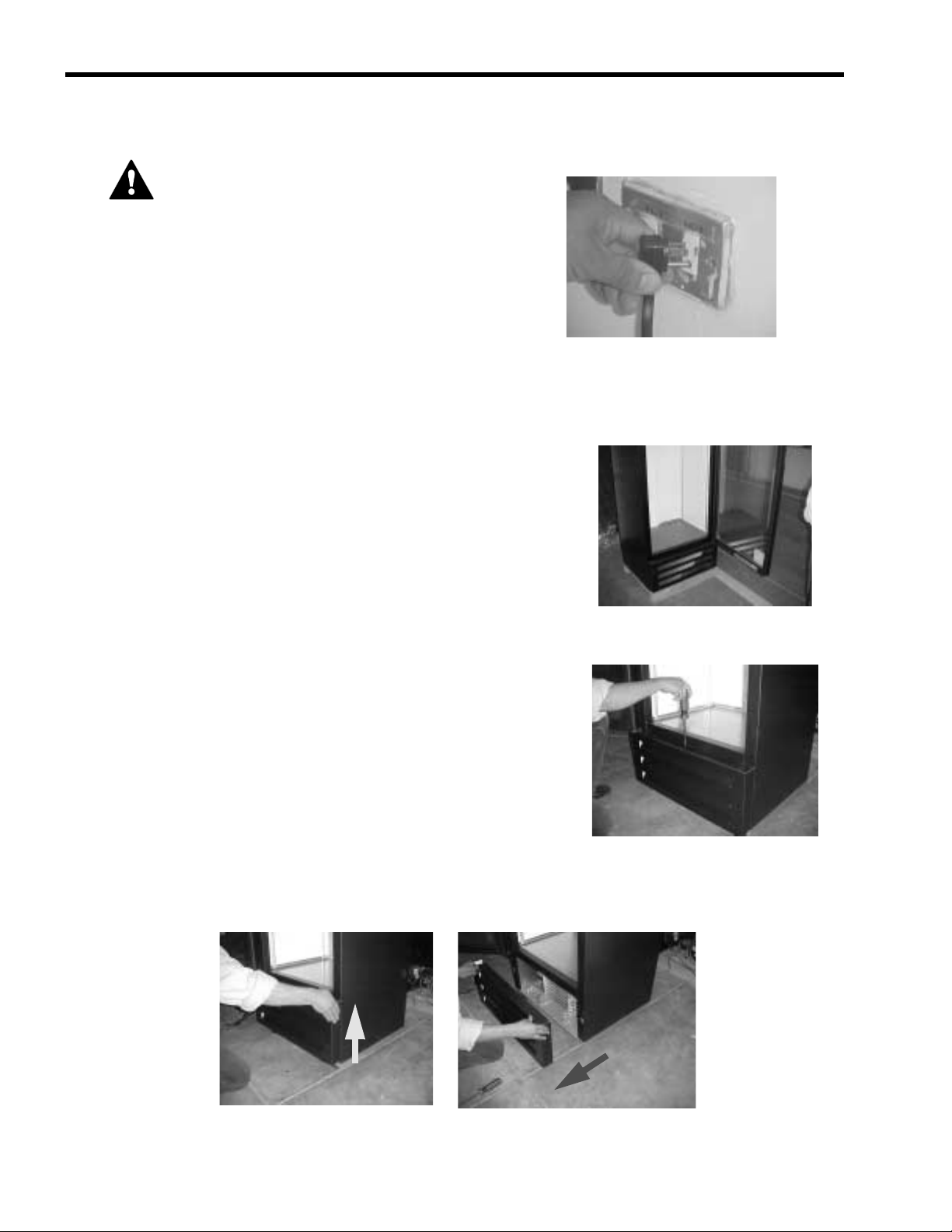
To remove the motor cover
1. Open the door.
2. Use a #2 Phillips screwdriver to remove the flat-head screw
holding condensing the unit motor cover.
3. Remove the condensing unit motor cover by pulling it up and out.
FIGURE 2
FIGURE 3
FIGURE 4
Publication Number: 630460243SER - 2 - © 2005, IMI Cornelius Inc.
Page 7
BALLAST REPLACEMENT
Required tool
• one #2 Phillips screwdriver with a 4” long blade
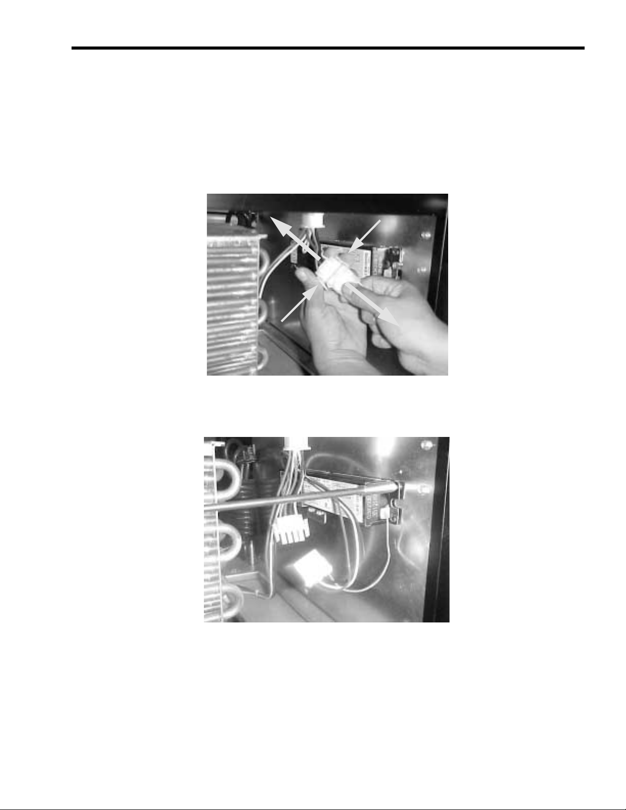
To remove the ballast
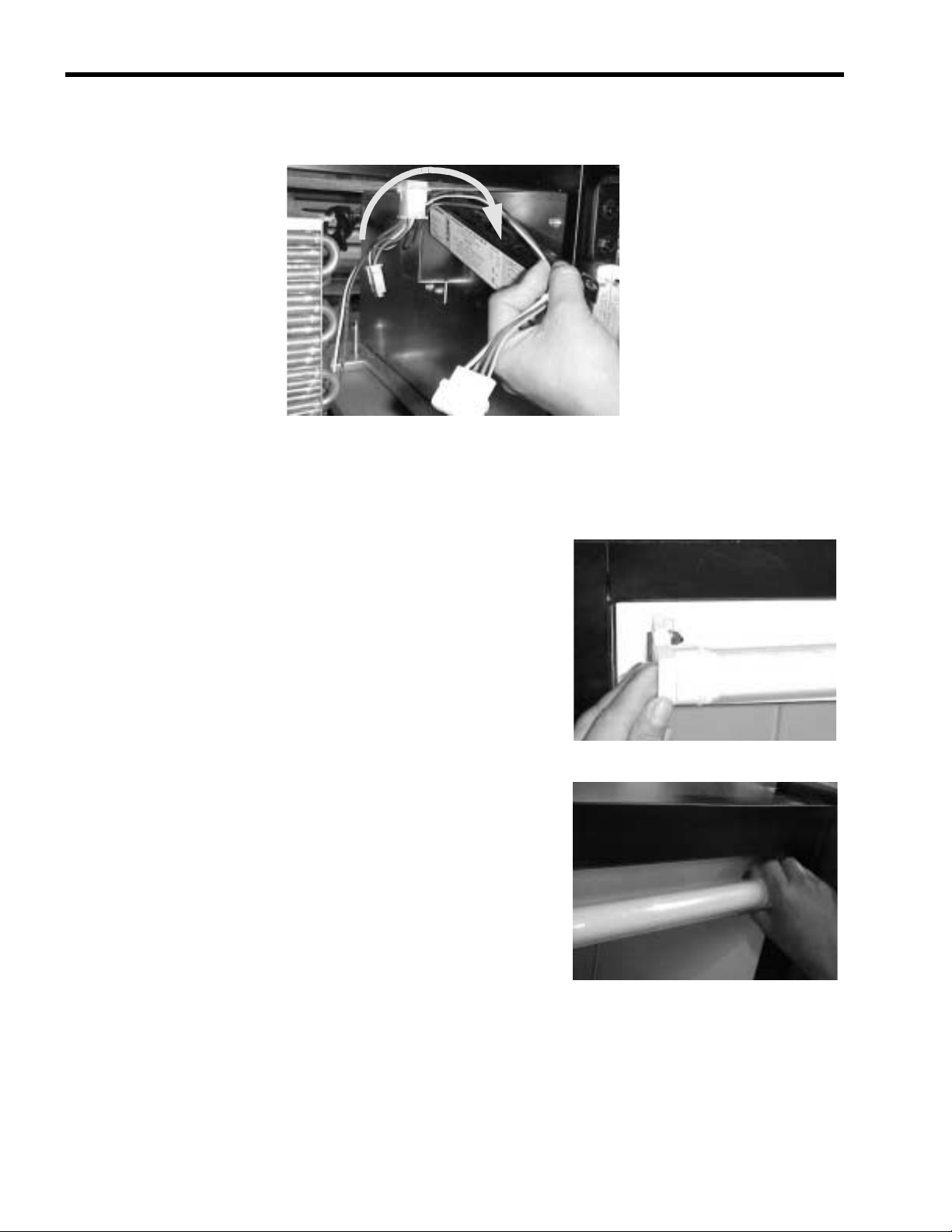
1. Push down with your fingers on the plastic tabs that hold the male and female connectors in
position. Then pull out the male connector (connected to the ballast).
Visual Merchandiser Service Manual
FIGURE 5
2. Use a Phillips screwdriver to remove the single screw holding the ballast to the metal bracket. The
ballast sits on a metal bracket to make replacement easier.
FIGURE 6
© 2005, IMI Cornelius Inc. - 3 - Publication Number: 630460243SER
Page 8
Visual Merchandiser Service Manual
3. To remove the ballast, lift the ballast wires over the metal bracket which holds the back end of the
ballast.
4. To reinstall a new ballast reverse steps 1 through 3.
FIGURE 7
To replace the fluorescent lamp
1. Pull one end of the lamp holder base half way out.
2. Pull the other end of the lamp holder base half way out.
FIGURE 8
FIGURE 9
Publication Number: 630460243SER - 4 - © 2005, IMI Cornelius Inc.
Page 9
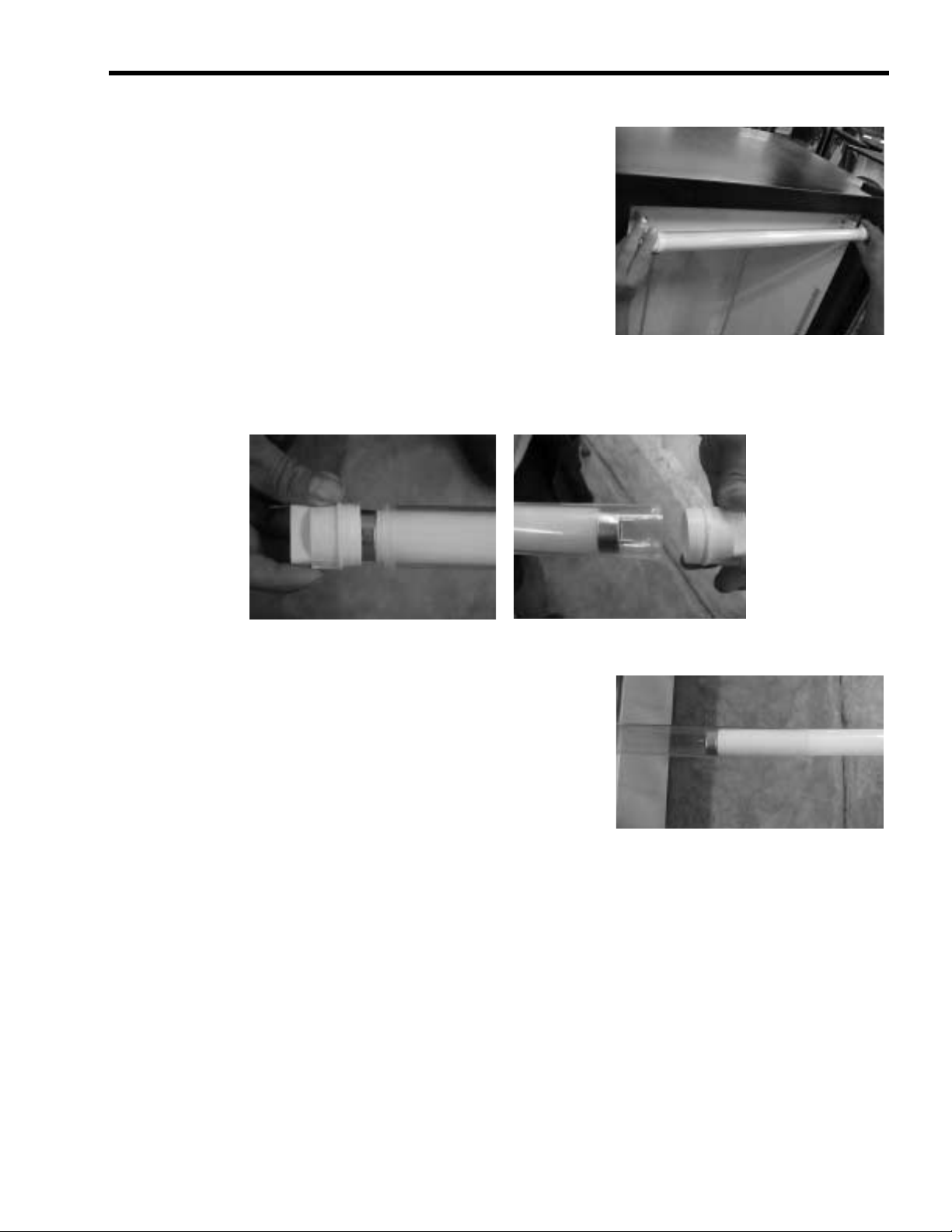
3. Once the two bases have been pulled half way out, use both
hands to pull out the entire lamp assembly
4. Remove the lamp holder bases from each end of the lamp.
Visual Merchandiser Service Manual
FIGURE 10
FIGURE 11
5. Remove the plastic cover from the lamp. Now you can
replace the lamp.
6. To install a new lamp, reverse steps 1 through 5.
FIGURE 12
© 2005, IMI Cornelius Inc. - 5 - Publication Number: 630460243SER
Page 10
Visual Merchandiser Service Manual
TEMPERATURE CONTROL REPLACEMENT
CAUTION - Make sure the power supply is
turned off before making any electrical
repairs.
If any electrical problems arise, a wiring diagram is included with each cabinet to aid in tracing the source
of trouble and making the necessary repairs.
Required tool
• one #2 Phillips screwdriver with a 4” long blade
To remove the temperature control
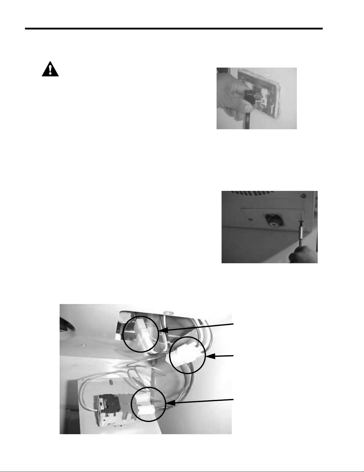
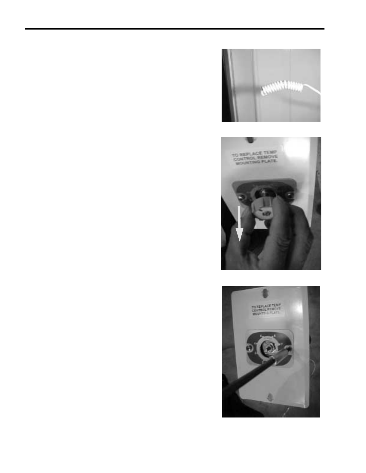
1. Remove the two Phillips head screws that hold the
temperature control mounting plate (located on the baffle).
FIGURE 13
With the temperature control mounting plate removed from the baffle, you can see the thermostat,
light, and fan motor connectors.
Evaporator fan motor connections
Fluorescent lamp connections
Temperature control connections
FIGURE 14
Publication Number: 630460243SER - 6 - © 2005, IMI Cornelius Inc.
Page 11
Visual Merchandiser Service Manual
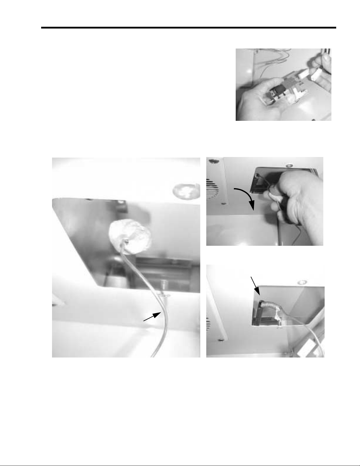
2. Disconnect the electrical connections from the temperature
control.
FIGURE 15
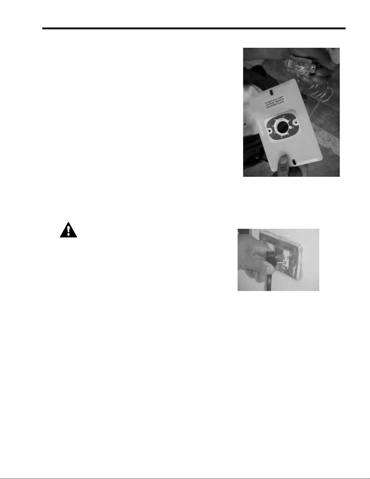
3. Carefully pull the bulb sensor out of the temperature control well. There is a patch of permagum at
the opening of the well which seals the bulb sensor from humidity.
Temperature control sensing bulb
Temperature control well
FIGURE 16
© 2005, IMI Cornelius Inc. - 7 - Publication Number: 630460243SER
Page 12
Visual Merchandiser Service Manual
The bulb sensor has a slight curve to make a tight fit inside
the temperature control well.
4. Remove the temperature control knob by pulling it outward.
FIGURE 17
5. Use a Phillips screwdriver to remove the two Phillips head
screws the hold the temperature control to its mounting
plate.
FIGURE 18
FIGURE 19
Publication Number: 630460243SER - 8 - © 2005, IMI Cornelius Inc.
Page 13
6. With the two Phillips head screws removed, you can now
install a new temperature control by reversing steps 1
through 5.
Visual Merchandiser Service Manual
FIGURE 20
EVAPORATOR FAN MOTOR REPLACEMENT
CAUTION - Make sure the power supply is
turned off before making any electrical
repairs.
If any electrical problems arise, a wiring diagram is included with each cabinet to aid in tracing the source
of trouble and making the necessary repairs.
Required tools
To replace the evaporator fan motor, you need:
• one #2 Phillips screwdriver with 4” blade
• one side-cutting pliers
• one 1/4” socket screwdriver
© 2005, IMI Cornelius Inc. - 9 - Publication Number: 630460243SER
Page 14
Visual Merchandiser Service Manual
To disconnect the evaporator fan motor electrical terminals
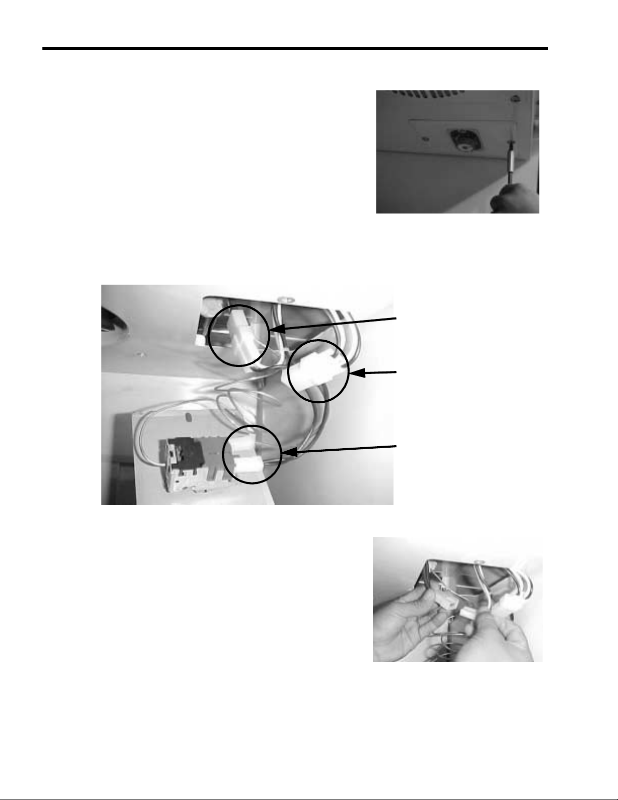
1. Remove the two Phillips head screws that hold the
temperature control mounting plate (located on the baffle).
With the temperature control mounting plate removed from the baffle, you can see the thermostat, light,
and fan motor connectors.
Evaporator fan motor connections
FIGURE 21
FIGURE 22
2. Disconnect the fan motor electrical connector.
Fluorescent lamp connections
Temperature control connections
FIGURE 23
Publication Number: 630460243SER - 10 - © 2005, IMI Cornelius Inc.
Page 15
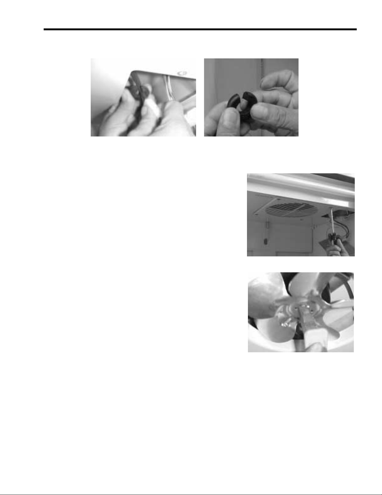
3. Remove the rubber grommet, located in the plastic bushing near at the right air diffuser.
To remove the evaporator fan motor
1. Use a Phillips screwdriver to remove the four screws holding
the evaporator fan grill at the baffle.
Visual Merchandiser Service Manual
FIGURE 24
2. Remove the fan blade. Use the side-cutting pliers to
unscrew the nut-type washer that holds the fan motor in
place.
FIGURE 25
FIGURE 26
© 2005, IMI Cornelius Inc. - 11 - Publication Number: 630460243SER
Page 16
Visual Merchandiser Service Manual
3. Pass the electrical wire of the motor through the plastic bushing on the air diffuser.
4. Use a Phillips screwdriver to remove the four screws holding the base of the fan motor to the top of
the internal cabinet.
Plastic bushing on the air diffuser
FIGURE 27
Four Phillips head screws
FIGURE 28
5. Use a 1/4” socket screwdriver to remove the three socket head screws holding the fan motor to its
base.
Three socket head screws
FIGURE 29
6. Replace the fan motor with another of the same model. Reinstall the fan motor by reversing steps 1
through 5.
Publication Number: 630460243SER - 12 - © 2005, IMI Cornelius Inc.
Page 17

CONDENSING UNIT FAN MOTOR REPLACEMENT
CAUTION - Make sure the power supply is
turned off before making any electrical
repairs.
If any electrical problems arise, a wiring diagram is included with each cabinet to aid in tracing the source
of trouble and making the necessary repairs.
Required tools
The following tools are required to repair the spring hinge system or assemble a new door:
• one Phillips #2 screwdriver with 4” blade
• one 3/8” open end or box end wrench
Visual Merchandiser Service Manual
• one 7/16” open end or box end wrench
• one adjustable wrench, 4” or 6”
• one measuring tape
To remove the motor cover
1. Open the door.
2. Use a #2 Phillips screwdriver to remove the flat-head screw
holding condensing the unit motor cover.
FIGURE 30
FIGURE 31
© 2005, IMI Cornelius Inc. - 13 - Publication Number: 630460243SER
Page 18

Visual Merchandiser Service Manual
3. Remove the condensing unit motor cover by pulling it up and out.
To pull out the condensing unit
1. Use a 1/2” open or box end wrench to remove the bolts that hold the rails that support the
condensing unit.
FIGURE 32
FIGURE 33
2. Slowly push the condensing unit from the rear of the cabinet. Be sure the suction line and the
capillary tubing do not break.
FIGURE 34
Publication Number: 630460243SER - 14 - © 2005, IMI Cornelius Inc.
Page 19

3. Pull the condensing unit about 13 inches from the base of the cabinet to provide access to the
condensing unit fan motor, relay, overload protector, and capacitor.
FIGURE 35
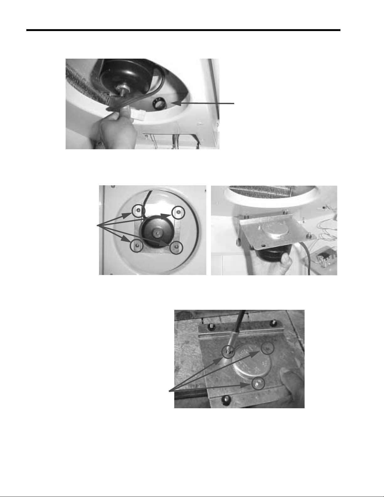
To replace the condensing unit fan motor
1. Untie the fan motor electrical wire.
Visual Merchandiser Service Manual
2. Disconnect the fan motor electrical connectors.
FIGURE 37
FIGURE 36
© 2005, IMI Cornelius Inc. - 15 - Publication Number: 630460243SER
Page 20

Visual Merchandiser Service Manual
3. Use a 7/16” open end or box end wrench to remove the four
nuts and bolts that hold the base of the fan motor to the rails
of the condensing unit.
4. Tilt the fan motor from one corner in the direction of the
arrow to remove the fan motor from the condenser shroud.
FIGURE 38
5. Pull the fan motor out in the direction of the arrow.
6. Use the side cutting pliers to remove the fan blade.
FIGURE 39
FIGURE 40
FIGURE 41
Publication Number: 630460243SER - 16 - © 2005, IMI Cornelius Inc.
Page 21

Visual Merchandiser Service Manual
7. Use a 1/4” socket screwdriver to loosen the four screws that hold the fan motor chassis to its
bracket. Replace the fan motor.
FIGURE 42
8. To reinstall the fan motor, reverse steps 1 through 7.
STARTING RELAY, OVERLOAD PROTECTOR, AND START CAPACITOR
R
EPLACEMENT
CAUTION - Make sure the power supply is
turned off before making any electrical
repairs.
If any electrical problems arise, a wiring diagram is included with each cabinet to aid in tracing the source
of trouble and making the necessary repairs.
Required tool
You will need one Phillips #2 screwdriver with 4” blade and one flat blade screwdriver.
To remove the motor cover
1. Open the door.
FIGURE 43
© 2005, IMI Cornelius Inc. - 17 - Publication Number: 630460243SER
Page 22

Visual Merchandiser Service Manual
2. Use a #2 Phillips screwdriver to remove the flat-head screw
holding condensing the unit motor cover.
3. Remove the condensing unit motor cover by pulling it up and out.
FIGURE 44
To pull out the condensing unit
1. Use a 1/2” open or box end wrench to remove the bolts that hold the rails that support the
condensing unit.
FIGURE 45
FIGURE 46
Publication Number: 630460243SER - 18 - © 2005, IMI Cornelius Inc.
Page 23

Visual Merchandiser Service Manual
2. Slowly push the condensing unit from the rear of the cabinet. Be sure the suction line and the
capillary tubing do not break.
FIGURE 47
3. Pull the condensing unit about 13 inches from the base of the cabinet to provide access to the
condensing unit fan motor, relay, overload protector, and capacitor.
FIGURE 48
© 2005, IMI Cornelius Inc. - 19 - Publication Number: 630460243SER
Page 24

Visual Merchandiser Service Manual
To remove the electrical box
1. Insert a flat blade screwdriver into the slot on the top of the plastic electrical box (attached to one
side of the compressor), push the screwdriver downward, and remove the box.
Slot on top of the electrical box
FIGURE 49
2. While pushing down on the slot, hold box with your other
hand and pull it out.
FIGURE 50
Publication Number: 630460243SER - 20 - © 2005, IMI Cornelius Inc.
Page 25

Visual Merchandiser Service Manual
3. Once the electrical box is removed from the compressor shell, the following components and wires
are visible:
• relay
• overload protector
• two black wires that connect to the starting capacitor
• ground wire (green)
• common wire (black)
• start winding (blue)
Starting relay
Two black wires
connected to the starting
capacitor
Ground wire
Overload protector
To replace the relay
1. Disconnect the two black starting capacitor wires and the blue start winding wire.
2. Use a slotted screwdriver as a pry bar to pull the relay from the compressor shell.
Blue start winding wire
Common wire
FIGURE 51
FIGURE 52
3. To reinstall the relay, reverse these steps.
© 2005, IMI Cornelius Inc. - 21 - Publication Number: 630460243SER
Page 26

Visual Merchandiser Service Manual
To replace the overload protector
1. Pull the overload protector from the compressor shell.
2. To reinstall the overload protector, reverse the above steps.
To replace the starting capacitor
1. Use a slotted screwdriver as a pry bar to remove the
starting capacitor from its base (attached to the top of the
plastic electrical box).
FIGURE 53
2. Remove the top of the starting capacitor to completely
detach it from its base.
3. To reinstall the starting capacitor, reverse these steps.
FIGURE 54
FIGURE 55
Publication Number: 630460243SER - 22 - © 2005, IMI Cornelius Inc.
Page 27

To install the electrical box
1. Be sure all wires are properly connected. The starting capacitor wires must pass through the slotted
channel on the box to ensure correct connection between the electrical box and the compressor
shell.
Visual Merchandiser Service Manual
Two wires from the starting
capacitor pass through the slotted
channel on the box.
FIGURE 56
2. Insert the top of the box into the compressor shell.
3. Use your hand to push the whole box until you hear a click.
FIGURE 57
FIGURE 58
© 2005, IMI Cornelius Inc. - 23 - Publication Number: 630460243SER
Page 28

Visual Merchandiser Service Manual
4. Slowly push the condensing unit back to its original position. Avoid breaking the suction line and
capillary tubing.
5. Re-tie all the wires.
FIGURE 59
FIGURE 60
6. Return the suction line and the capillary tubing to their
original positions.
Re-tie all the wires
FIGURE 61
Publication Number: 630460243SER - 24 - © 2005, IMI Cornelius Inc.
Page 29

DOOR AND SPRING HINGE SYSTEM
CAUTION - Make sure the power supply is
turned off before making any electrical
repairs.
Required tools
The following tools are required to repair the spring hinge system or assemble a new door:
• one Phillips #2 screwdriver with 4” blade
• one 3/8” open end or box end wrench
• one 7/16” open end or box end wrench
• one adjustable wrench, 4” or 6”
Visual Merchandiser Service Manual
• one measuring tape
To remove the motor cover
1. Open the door.
2. Use a #2 Phillips screwdriver to remove the flat-head screw
holding condensing the unit motor cover.
FIGURE 62
FIGURE 63
© 2005, IMI Cornelius Inc. - 25 - Publication Number: 630460243SER
Page 30

Visual Merchandiser Service Manual
3. Remove the condensing unit motor cover by pulling it up and out.
To remove the door
NOTE: Reinstall the door support bracket before removing
the door. The door support bracket allows door removal to be
performed by just one person.
FIGURE 64
FIGURE 65
1. Use a Phillips screwdriver to remove the door support bracket from the condensing unit
compartment, held in place by two Phillips screws. This bracket has been placed on the interior left
side wall of the condensing unit compartment for storage purposes only.
FIGURE 66
Publication Number: 630460243SER - 26 - © 2005, IMI Cornelius Inc.
Page 31

Visual Merchandiser Service Manual
2. Using the same two Phillips screws, reinstall the door support bracket in the two holes located on
the bottom of the door frame.
FIGURE 67
3. This photo shows the door support bracket installed and
holding the door.
4. Relieve the tension in the spring hinge, located at the
bottom hinge of the door, before beginning work on the
spring hinge system.
5. The securing nut is right-hand threaded. Use a 7/16”
wrench to turn the nut clockwise one and one half turns to
loosen it.
FIGURE 68
FIGURE 69
FIGURE 70
© 2005, IMI Cornelius Inc. - 27 - Publication Number: 630460243SER
Page 32

Visual Merchandiser Service Manual
6. One end of the main rod has a square head which is used to adjust the spring tension using an
adjustable wrench. One of the faces of the square head has an indentation and is painted red. This
red indentation should face the right-hand side of the cabinet when the spring has tension.
Securing nut
Square end of main rod
Position of the main rod when
the spring has tension
FIGURE 71
7. Use the red indentation as a point of reference to turn the main rod 3/4 of a turn counterclockwise
to relieve the spring tension. The red mark should face away from the cabinet front when the spring
tension has been relieved.
Red mark faces away
from the cabinet after
the spring tension has
been relieved.
FIGURE 72
Decrease the spring tension by turning the main rod counterclockwise.
8. Use a 3/8” wrench to remove the two screws that hold the
bottom hinge in place.
FIGURE 73
Publication Number: 630460243SER - 28 - © 2005, IMI Cornelius Inc.
Page 33

Visual Merchandiser Service Manual
IMPORTANT: The door support bracket must be installed for a single person to remove the door.
9. Pull the door downward to separate the door from the top hinge.
FIGURE 74
To install the door
NOTE: Reinstall the door support bracket before installing
the door. The door support bracket allows door installation to be
performed by just one person.
FIGURE 75
© 2005, IMI Cornelius Inc. - 29 - Publication Number: 630460243SER
Page 34

Visual Merchandiser Service Manual
The springe hinge system consists of a securing nut, a pressure washer, the main rod, the bottom hinge,
an axial ball bearing, a plastic bushing, and the spring torsion.
Axial ball bearing
Plastic bushing
Main rod
Pressure washer
Bottom hinge
Spring hinge
Securing nut
FIGURE 76
1. Slowly insert the spring hinge system. Make sure the spring arm goes through the slot on the
plastic profile.
Slot on the plastic profile
Slot
FIGURE 77
Spring arm
Publication Number: 630460243SER - 30 - © 2005, IMI Cornelius Inc.
Page 35

Visual Merchandiser Service Manual
2. After the spring hinge system has been inserted into the door frame, use a piece of masking tape to
hold it in place so it will not fall out when putting the door back into the cabinet.
FIGURE 78
NOTE: Make sure the door support bracket is in place before reinstalling the door. Refer to the
instructions at the beginning of the section “To remove the door.”
3. Insert the door onto the pin of the top hinge by pushing the door upward.
FIGURE 79
4. Insert the two screws that hold the bottom hinge in place and tighten them with a 3/8” wrench.
FIGURE 80
© 2005, IMI Cornelius Inc. - 31 - Publication Number: 630460243SER
Page 36

Visual Merchandiser Service Manual
5. The securing nut is right-hand threaded. Use a 7/16” wrench to turn the nut clockwise one and onehalf turns to loosen it. The red indentation should face away from the cabinet front before tensioning
the spring.
6. Turn the main rod clockwise 3/4 turn with the adjustable wrench using the red indentation as
reference. Tighten the nut on the hinge with the 7/16” wrench by turning it counterclockwise so the
spring hinge tension is not lost. Tighten the nut by turning the wrench counterclockwise.
Red indentation
faces away from the
cabinet before
tensioning the
spring
FIGURE 81
FIGURE 82
Increase spring tension by turning the main rod clockwise.
7. The red indentation should face the right side of the cabinet when the spring has tension.
Red indentation
faces the right side
Securing nut
Square end of main rod
FIGURE 83
Publication Number: 630460243SER - 32 - © 2005, IMI Cornelius Inc.
of the cabinet when
the spring has
tension
Page 37

Visual Merchandiser Service Manual
8. Test the tension of the door by opening it and letting it close by itself.
FIGURE 84
9. Remove the door support bracket and reattach it to the interior left side wall of the condensing unit
compartment for storage.
10. Replace the condensing unit motor cover by reversing the procedure to remove the motor cover.
© 2005, IMI Cornelius Inc. - 33 - Publication Number: 630460243SER
Page 38

Visual Merchandiser Service Manual
To assemble spring hinge components
The springe hinge system consists of a securing nut, a pressure washer, the main rod, the bottom hinge,
an axial ball bearing, a plastic bushing, and the spring torsion.
Axial ball bearing
Plastic bushing
Main rod
Pressure washer
Bottom hinge
Spring hinge
FIGURE 85
Securing nut
1. Insert the square end of the main rod into the spring-curved
arm.
2. Hook the end of the main rod that goes inside the door to
the spring as shown in the photo to ensure proper main rod
and spring hinge assembly.
FIGURE 86
FIGURE 87
Publication Number: 630460243SER - 34 - © 2005, IMI Cornelius Inc.
Page 39

3. Insert the plastic bushing as shown in the photo.
4. Then insert the axial ball bearing. The bearing consists of
two flat washers with the bearing between them.
Visual Merchandiser Service Manual
FIGURE 88
5. The hinge has a 1/4:-28 right-hand threaded hole. Screw
the main rod to the bottom hinge by turning the bottom
hinge clockwise.
6. Make sure the main rod extends 1/2” beyond the hinge.
FIGURE 89
FIGURE 90
FIGURE 91
© 2005, IMI Cornelius Inc. - 35 - Publication Number: 630460243SER
Page 40

Visual Merchandiser Service Manual
7. Insert the pressure washer before inserting the securing
nut.
8. Then insert the securing nut.
FIGURE 92
9. Use high temperature bearing grease before inserting the
spring hinge system into the door frame.
FIGURE 93
FIGURE 94
Publication Number: 630460243SER - 36 - © 2005, IMI Cornelius Inc.
Page 41

Visual Merchandiser Service Manual
10. Add grease between the plastic bushing and the spring arm and to the axial ball bearing.
FIGURE 95
The complete spring hinge system looks like this:
Axial ball bearing
Plastic bushing
Main rod
Pressure washer
Spring hinge
Bottom hinge
Securing nut
FIGURE 96
© 2005, IMI Cornelius Inc. - 37 - Publication Number: 630460243SER
Page 42

Visual Merchandiser Service Manual
11. Finish the spring hinge assembly by using a 7/16” wrench to
tighten the securing nut before installing the spring hinge
system to the door.
12. Refer to the photo at right to be sure you have the rod ends
correctly aligned with the bottom hinge before inserting it
into the door frame.
FIGURE 97
FIGURE 98
Publication Number: 630460243SER - 38 - © 2005, IMI Cornelius Inc.
Page 43

GLASS DOOR PANE REPLACEMENT
To remove the motor cover and door
Refer to the previous section for removal of the motor cover and door.
Required tools
• one scraper
• one rubber mallet
To remove the glass door pane
1. Place the door, with the gasket facing up, on two 2” X 2”
pieces of wood on a table.
Visual Merchandiser Service Manual
FIGURE 99
2. The glass pane is held in place by four pieces of plastic trip, inserted around the door frame. Use a
scraper to remove the two long plastic trims first and then the two short ones.
Removable plastic trim
FIGURE 100
IMPORTANT: First, remove the long trims, then remove the short ones. It is not necessary to
remove the gasket seal to replace the glass pane.
© 2005, IMI Cornelius Inc. - 39 - Publication Number: 630460243SER
Page 44

Visual Merchandiser Service Manual
3. Insert the scraper into the groove of the trim at the middle of one of the long pieces. Push the trim
up and towards the center of the glass as shown.
Scraper
Door gasket seal
4. Remove the trim by hand.
Removable plastic trim
Door frame
FIGURE 101
Glass pane
5. Remove the other three trims in the same way.
FIGURE 102
FIGURE 103
Publication Number: 630460243SER - 40 - © 2005, IMI Cornelius Inc.
Page 45

Visual Merchandiser Service Manual
G
G
Pl
6. Place one hand underneath the glass pane and push it up to separate it from the door frame.
lass pane
Door frame
FIGURE 104
7. Carefully place the new glass pane inside the plastic door
frame.
lass pane
Door frame
FIGURE 105
8. Beginning at the corners, insert one of the short plastic trims into the groove in the door frame.
astic trim inserted at left corner
Plastic trim inserted at right corner
FIGURE 106
© 2005, IMI Cornelius Inc. - 41 - Publication Number: 630460243SER
Page 46

Visual Merchandiser Service Manual
9. Push the trim in the middle by hand and finish inserting it using a rubber mallet as shown in the
photo.
10. Follow steps 8 and 9 to insert the remaining trims.
To install the door
Follow the instructions in the previous section to re-install the door.
FIGURE 107
REFRIGERATION SYSTEM
Compressor
The compressor is a factory-sealed unit located underneath (outside) the cooling cabinet. This pump is
activated by a motor which draws low-pressure vapor (refrigerant) from the evaporator. It then
compresses the gas and forces it into the condenser at a high pressure.
Starter relay
The starter relay is attached on one side of the compressor box. The compressor motor has two
windings: one for starting and another for running. In order to provide the necessary additional torque
when the motor is first started, the starter relay connects the additional start-up windings. After the motor
reaches its correct operating speed, the relay opens the ignition windings and the motor continues with
the operation windings.
Thermal protector
This protector is a thermo-sensible device attached to one side of the compressor’s box. In any given
situation, if the compressor overheats or if the voltage source varies drastically, the thermal protector
opens, turning off the compressor. After the compressor cools down to a normal and safe working
temperature, the thermal protector turns on the compressor.
Condenser
The condenser is located underneath (outside) the cooling cabinet in front of the compressor. It receives
hot, high-pressure refrigerant gas from the compressor and cools it down until it returns to a liquid state.
Publication Number: 630460243SER - 42 - © 2005, IMI Cornelius Inc.
Page 47

Condenser fan motor
The condenser fan motor is located underneath the cooling cabinet. It is a ventilation device which forces
the ambient air to flow over the condenser to cool down the refrigerant flowing inside it. The fan motor
works only if the compressor is on.
Visual Merchandiser Service Manual
Evaporator
The evaporator is located inside the cooling cabinet. As the gas flows at a low pressure through the
evaporator, it absorbs heat through the copper coil from inside the cabinet.
EVAPORATOR
FAN M OTOR
EVAPORATOR
ACCUMULATOR
CAPILLARY
SUCTION
COMPRESSOR
FIGURE 108
DRIER
DISCHARGE
CONDENSER
CONDENSER
FAN MOTOR
LEGEND
R-134A
FLOW
Evaporator fan motor
This device provides the required circulation of air through the cooling cabinet as well as over the surface
of the evaporator’s serpentine thermal exchange area. This fan motor runs continuously.
The evaporator and condenser serpentines have aluminum fins that help increase the surfaces for the
thermal exchange in an efficient way.
Capillary tube
It consists of several feet of tubing having a small inside diameter. It is a device used to control the
amount of refrigerant that flows into the evaporator.
Drier
The drier is located in between the condenser and the evaporator. It traps and removes moisture in the
refrigeration system while allowing oil and refrigerant to flow freely.
Accumulator
The accumulator is located in between the evaporator and the compressor. It is a storage tank which
receives refrigerant liquid from the evaporator and prevents it from flowing into the compressor.
Temperature control
The adjustable temperature control is responsible for detecting temperature changes inside the cooling
cabinet. It also starts the compressor motor whenever the cabinet rises above the desired temperature.
© 2005, IMI Cornelius Inc. - 43 - Publication Number: 630460243SER
Page 48

Visual Merchandiser Service Manual
The temperature control consists of a switch which is mechanically activated by a diaphragm. This
diaphragm is connected to a thermo-sensible bulb (located inside the cabinet) through a small diameter
tube. All three components (the diaphragm, the thermo-sensible bulb, and the small diameter tube) are
filled with refrigerant gas which reacts to temperature changes.
When the cabinet temperature rises, the refrigerant in the bulb heats up and expands, expanding the
diaphragm. The diaphragm’s expanding closes the temperature control’s interrupting device and then
starts the compressor and condenser motors.
The drop in temperature inside the cooling compartment is caused by the refrigerant’s continuous
circulation through the system. When the temperature drops, the refrigerant inside the temperature
control’s bulb contracts, allowing the diaphragm to open the interrupting device, which consequently
shuts down the compressor and condenser motors.
Cooling cabinet
This is the area where the goods are stored. It has been designed to allow for constant cold air circulation
to flow through the goods.
THE REFRIGERATION CYCLE
1. Depending on the increase in temperature inside the cooling compartment, the refrigerant gas
inside the temperature control's bulb heats up and expands, expanding the diaphragm. The
diaphragm's expansion closes the temperature control's interrupting device.
2. The temperature control's interrupting device turns on the compressor and condenser motors.
3. The compressor recirculates the refrigerant throughout the system by drawing the refrigerant gas
as low vapor pressure from the evaporator. Then it compresses the refrigerant and forces it into the
condenser.
4. The condenser, with the help of its fan motor, removes the refrigerant's heat as it flows through the
condenser. The heat is then released to the outside environment. Consequently, the decrease in
temperature will change the refrigerant from a gaseous to a liquid state.
5. The capillary tube regulates the amount of refrigerant that is discharged into the evaporator.
6. The evaporator's serpentine allows the refrigerant to absorb and remove heat from the cooling
compartment.
7. The drop in temperature inside the cooling compartment is caused by the refrigerant's continuous
circulation through the system. This gas continuously absorbs the heat that exists inside the cooling
compartment and expels it to the outside environment. When the temperature drops, the refrigerant
inside the temperature control's bulb contracts, allowing the diaphragm to open the interrupting
device, which consequently shuts down the compressor and condenser motors.
Publication Number: 630460243SER - 44 - © 2005, IMI Cornelius Inc.
Page 49

WIRING DIAGRAM 115 V/60 HZ/1 PHASE
Visual Merchandiser Service Manual
FIGURE 109
© 2005, IMI Cornelius Inc. - 45 - Publication Number: 630460243SER
Page 50

Visual Merchandiser Service Manual
TROUBLESHOOTING
Possible causes and solutions
PROBLEM POSSIBLE CAUSE SOLUTION
COMPRESSOR WILL NOT
START
No voltage in the electrical
socket.
The electrical conductor or
wires may be cut.
Defective electrical
components such as:
thermostat, relay, thermal
protector, etc.
Thermostat in “off” position. Turn the thermostat’s knob to
Compressor motor has a
winding open or shorted.
Dirty condenser; lack of air
flow.
Low voltage. Use a voltage regulator if the
Compressor is stuck. Change the compressor.
Use a voltmeter to check the
voltage.
Use an ohmmeter to check for
continuity.
Replace defective components.
its maximum position and wait
to see if the compressor starts.
Measure the ohmic resistance
of the main and auxiliary
windings using an ohmmeter.
Compare them with the correct
values.
Clean condenser and allow for
air circulation.
voltage is lower than 103 volts.
THE TEMPERATURE IS TOO
COLD
THE TEMPERATURE IS NOT
COLD ENOUGH
Thermostat knob is set at a
very cold position.
Thermostat does not
disconnect the condensing unit.
Thermostat capillary bulb is
loose or installed improperly.
Thermostat knob is set at a
very warm position.
Condenser is dirty; lack of air
flow.
The refrigerator has been
placed at an inadequate
location.
Set the thermostat knob to a
warmer position and check if
the compressor stops
according to the thermostat’s
operating range.
Check the insulation of the
thermostat. If the problem
persists, change the
thermostat.
Correctly fasten the thermostat
capillary bulb.
Set the thermostat knob to a
colder position.
Clean the condenser and allow
for air circulation.
The unit must not be near
stoves, walls that are exposed
to the sun, or places that lack
sufficient air flow.
Publication Number: 630460243SER - 46 - © 2005, IMI Cornelius Inc.
Page 51

Visual Merchandiser Service Manual
PROBLEM POSSIBLE CAUSE SOLUTION
THE TEMPERATURE IS NOT
COLD ENOUGH
The refrigerator has been used
improperly.
The refrigerator has been
overcharged with the
refrigerant gas.
The refrigerant gas is leaking. Find the location where the gas
The evaporator and/or
condenser fans aren’t working.
Low voltage. Use a voltage regulator if the
ELECTRICAL SHOCKS Wires or electrical components
are in direct contact with
metallic parts.
The shelves must never be
covered with any type of plastic
or other material that will block
the circulation of cold air within
the refrigerator.
Check to see if condensation or
ice crystals have formed on the
suction line. If so, charge with
the correct amount of gas.
is leaking in order to seal it or
replace the defective
component. Change the drier.
Perform a good vacuum and
recharge the unit.
Check the electrical
connections and make sure
that the fan blade isn’t stuck.
Replace the fan motor if it
doesn’t work.
voltage is lower than 103 volts.
Check for appropriate
insulation on the connections of
each electrical component.
NOISE The refrigerator is not properly
leveled.
The condenser is not fastened
correctly. Copper tubings are in
contact with metal.
The evaporator and/or
condenser fans are loose.
Compressor has an internal
noise.
EXTREME CONDENSATION
INSIDE THE REFRIGERATOR
Thermostat knob is set at a
very cold position.
The outside environment’s
relative humidity is very high
(over 75%).
Check if the noise goes away
after you level the refrigerator.
While the compressor is
working, check to see if metal
parts are in contact with one
another and/or if the screws
that fasten the condenser are
tightened.
Check if the fans are securely
fastened. Also, check if the fan
blades are loose, broken or
crooked. If so, change the
faulty blade.
If the noise persists after all
other measures have been
taken, it may be originating
from the compressor.
Set the thermostat knob to a
warmer position and check if
the compressor stops
according to the thermostat’s
operating range.
This type of occurrence is
caused by local climatic
conditions and not by the
refrigerated unit.
© 2005, IMI Cornelius Inc. - 47 - Publication Number: 630460243SER
Page 52

Visual Merchandiser Service Manual
PROBLEM POSSIBLE CAUSE SOLUTION
EXTREME CONDENSATION
INSIDE THE REFRIGERATOR
The refrigerator door won’t shut
completely.
The refrigerator has been
placed at an inadequate
location.
NO ILLUMINATION The light switch is in “off”
position.
False contact on the light
switch, the fluorescent tube, or
the ballast.
Light switch, ballast and/or
fluorescent tube are damaged.
Check the door and/or the
magnetic gasket. Adjust the
door hinges if needed; replace
the gasket if broken.
The unit must not be near
sources that produce too much
heat.
Press the light switch to the
“on” position.
Inspect all connections.
Replace the damaged
component.
Publication Number: 630460243SER - 48 - © 2005, IMI Cornelius Inc.
 Loading...