

Page 1
IMI CORNELIUS INC.
One Cornelius Place
Anoka, MN. 55303 -6234
Telephone(612) 421-6120
Facsimile (612) 422 -3232
INSTALLATION & MAINTENANCE MANUAL
COLD CARB VENTURE
This is the Installation and Maintenance Manual for the Venture Post-Mix Dispenser with cold carbonator and
1/4 H.P. refrigeration compressor. The Venture Dispenser may be installed on a front or rear counter. A full
Installatio/Service Manual (P/N 318832000) is available upon request.
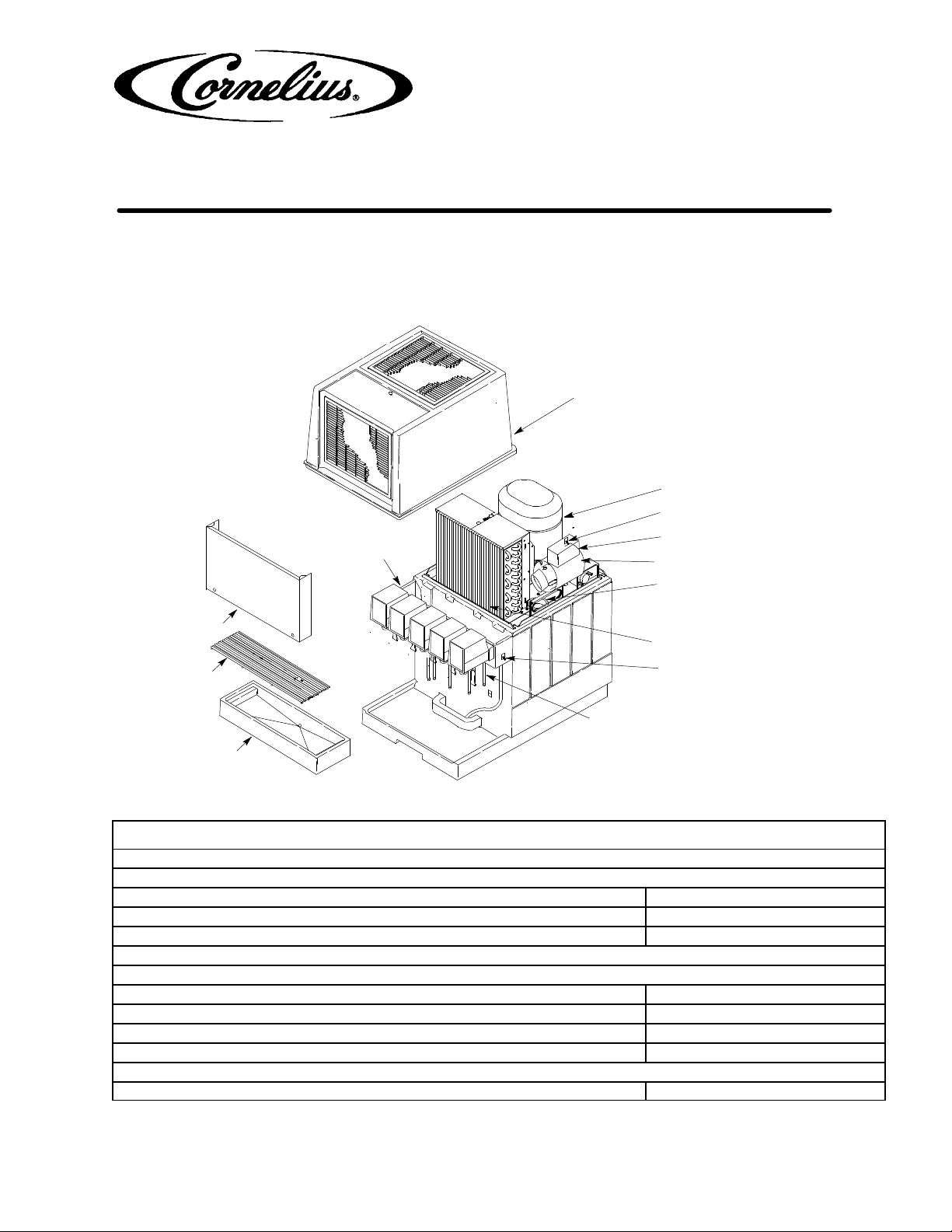
HOOD
COMPRESSOR
CARBONAT ORSWITCH
DISPENSING VALVES
KEY-LOCK SWITCH
CONTROL BOX
WATER PUMP AND MOTOR
WATER FILL HOLE PLUG
FRONT
ACCESS PANEL
CUP
REST
SYRUP STAINLESS-
STEEL INLET TUBES
DRIP
TRAY
CONDENSER COIL
ON/OFF SWITCH
(ON 115 VOLT UNITS ONL Y)
FIGURE 1. PARTS IDENTIFICA TION
Design Data
Dimensions:
Width 16-1/4 inches
Height 27-5/8 inches
Depth 24-1/2 inches
Weights:
Shipping Weight (approx) 128 pounds
Dry Weight (approx) 107 pounds
Ice Bank Weight (approx) 30 pounds
Drop-In Refrigeration Assembly 66 pounds
Water Tank Capacity (no ice bank) approx 9-3/4 gallons
EIMI Cornelius Inc; 1995--98
Control Code B
Revised: January 16, 1998
June 6, 1995
Page 2

Page 3
Design Data (cont’d)
Dispensing Rate: 12-oz. drinks 4/min. 40° F or below (see Note) *248
NOTE: *Approximate number of drinks dispensed 40° F or below 4@ 75° F syrup and water inlet tem-
perature and
75° F ambient.
Refrigeration Requirements:
Refrigerant Type and Amount See Unit
Nameplate
Ambient Operating Temperature 40° F to 120° F
Electrical Requirements: See Unit nameplate
UNPACKING AND INSPECTION
NOTE: The Unit was thoroughly inspected before leaving the factory and the carrier has accepted and
signed for it. Any damage or irregularities should be noted at the time of delivery (or not later than 15
days from date of delivery) and immediately reported to the delivering carrier. Request a written inspection report from Claims Inspector to substantiate any necessary claim. File claim with the delivering
carrier, not with IMI Cornelius Inc.
INSTALLATION
NOTE: Optional 4-inch Legs (P/N 31474400) that will elevate the Unit 4-inches above the countertop are
available. When ordering legs, order a quantity of four.
WARNING: To avoid possible fatal electrical shock or serious injury to the operator, it is
required that a GFCI (ground fault circuit interrupt) be installed in the electrical circuit for
the domestic Units. It is required that an ELCB (earth leakage circuit breaker) be installed in
the electrical circuit for the export Units
IMPORTANT: It is the responsibility of the Installer to ensure that the water supply system that is to be
connected to the dispensing equipment is provided with protection against back flow by an air gap as
defined in ANSI/ASME A112.1.2--1979; or an approved vacuum breaker or other such method as proved
effective by test.
Water pipe connections and fixtures directly connected to a potable water supply shall be sized,
installed, and maintained according to Federal, State, and local laws.
CAUTION: This Unit is intended for indoor installation only. Do not install this Unit in an
outdoor environment which would expose it to the outside elements.
Note: A minimum of 15-inches clearance must be maintained above the Unit to the nearest object
(shelf, cupboard, ceiling, etc.). The front grille of the Unit must be unobstructed to allow air to enter the
Unit hood.
The Unit must be located close to a permanent drain to connect the Unit drip tray drain hose.
The Unit must be installed near a properly grounded electrical outlet with proper electrical require-
ments.The electrical circuit must be properly fused (slow-blow type fuse) or the circuit must be connected through an equivalent HACR circuit breaker.The electrical outlet must be accessible for ease of
connecting and disconnecting the Unit power cord. No other electrical equipment should be connected to this circuit. REFER TO UNIT NAMEPLATE FOR THE REQUIRED POWER CIRCUIT OPERATING
VOLTAGE, HZ, AND THE MINIMUM CIRCUIT AMPACITY OF THE UNIT. ALL ELECTRICAL WIRING MUST
CONFORM TO NATIONAL AND LOCAL ELECTRICAL CODES.
2 318832013
Page 4
1. Install drain hose on Unit and secure with provided clamp.
2. Route drip tray drain tube down to and connect to permanent drain.
Note: The Unit syrup, water and CO2source tubes may either be routed in through opening in lower
back side of the Unit to location behind the front panel or tubes may be routed up through hole cut in
the countertop to inside of the Unit. Cut necessary hole in countertop if applicable.
3. Remove Unit front access panel (see Figure 1) for access to the Unit syrup connecting tubes and for routing water inlet tube to the water pump.
4. Route syrup source tubes (numbered for identification) up to and to inside of the Unit. Connect numbered
syrup source tubes to matching number labeled Unit syrup inlet tubes.
5. Route plain water source tube up to the Unit. Connect plain water source tube to water pump inlet on water
pump and motor assembly .
6. Route CO2source tube up to the Unit. Connect CO2source tube to labeled Unit CO2inlet tube.
7. Place Unit in operating position on the countertop. To meet NSF International (NSF) requirements, seal
Unit to countertop with silastic sealant, such as Dow Corning RTV 731 or equivalent.
8. Remove hood from Unit. Fill water tank with clean water until water runs out of overflow into the drip tray
pan. Use low-mineral-content water where a local water problem exists.
WARNING: The Unit must be electrically grounded to avoid possible fatal electrical shock
or serious injury to the operator. The Unit power cord is equipped with a three-prong plug.
If a three-hole (grounded) electrical outlet is not available, use an approved method to
ground the Unit.
9. Plug Unit power cord into electrical outlet.
10. Place Unit power switch in “ON” position. Refrigeration system will start and begin building an ice bank.
WARNING: CO2displaces oxygen. Strict attention must be observed in the prevention of
CO2(carbon dioxide) gas leaks in the entire CO2and soft drink system. If a CO2gas leak is
suspected, particularly in a small area, immediately ventilate the contaminated area before
attempting to repair the leak. Personnel exposed to high concentration of CO2gas will experience
tremors which are followed rapidly by loss of consciousness and suffocation.
11. Make sure primary and secondary CO2regulators adjusting screws are turned to the left (counterclockwise) until all tension is relieved from adjusting screws springs, then open the CO2cylinder shutoff valve.
12. Adjusting CO2regulators.
A. Adjust secondary CO2regulator for the dispenser integral carbonator to nominal 80-psig. INLET CO
PRESSURE TO CARBONATOR MUST NOT EXCEED 125-PSIG.
2
B. Sugar syrup tanks Secondary CO2regulator-- Adjust sugar syrup tanks secondary CO2regulator to a
minimum of 45-psig.
C. Low-calorie (diet) syrup tank secondary CO2regulator-- Adjust low-calorie (diet) syrup tank secondary
CO2regulator to 10-psig for syrup lines up to 30-feet in length. Syrup lines longer than 30-feet in length
may require a slightly higher setting of 12-psig maximum. Excessive CO2pressure may cause low-calorie
syrup carbonation resulting in a foamy drink being dispensed.
D. Bag-in-Box System syrup pumps--Adjust the Bag-in-Box system syrup pumps secondary CO2regulator
to 70-psig. DO NOT EXCEED MAXIMUM PRESSURE SPECIFIED ON THE SYRUP PUMPS.
13. Turn on water supply to the Unit. Check for water leaks and repair if evident.
3318832013
Page 5
14. Place the switch on the control box, in “ON” position to start the carbonator motor.
15. Make sure Dispensing Valves key-lock power switch on left side of the Unit, is in the “ON” position, then
dispense from all Dispensing Valves to bleed all air from the water systems.
16. Remove dispensing valve covers.
17. Adjust Dispensing Valves for desired water flow rate. Turn water flow regulators to the left (counterclockwise) for less water or to the right (clockwise) for more water.
18. Connect syrup supplies into syrup systems.
19. Dispense from all Dispensing Valves to bleed all air from syrup systems. Check for syrup and water leaks
and repair any leaks.
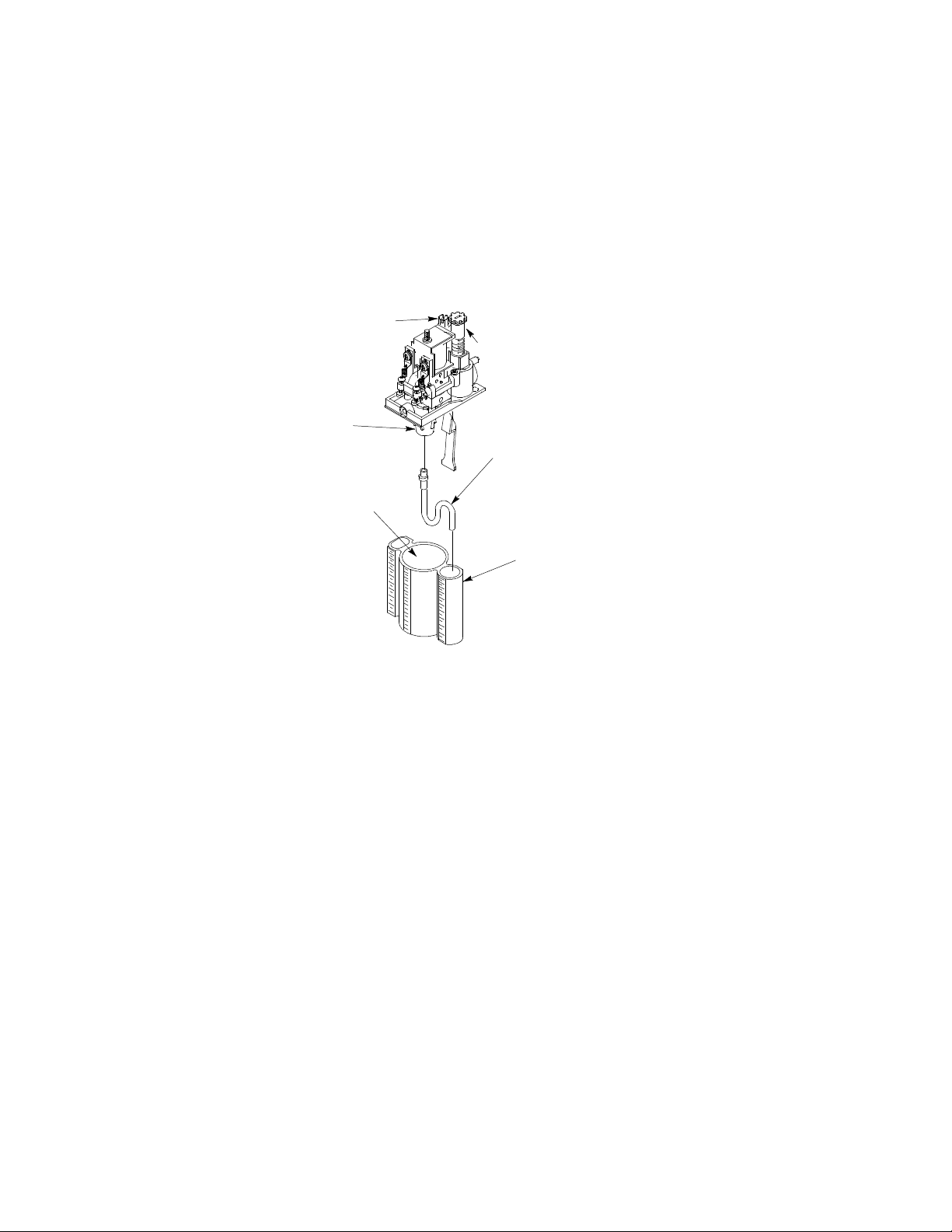
ADJUSTABLE WATER
FLOW REGULATOR
NOZZLE
WATER
CHAMBER
ADJUSTABLE SYRUP
FLOW REGULATOR
SYRUP BY-PASS
TUBE ASS’Y
(P/N 319540000)
RATIO CUP
(P/N 31 1100000)
FIGURE 2. RATIO CUP AND SYRUP DIVERSION TUBE
20. Adjust Dispensing Valves for Water-To-Syrup “Ratio” of dispensed drinks as follows:
Note: Refer to syrup manufacturer’s recommendations on syrup package for Water-to-Syrup “Ratio”.
A. Hold container under dispensing valve. Open dispensing valve and dispense just enough to fill syrup
by-pass tube with syrup.
B. Hold large chamber of ratio cup under dispensing valve nozzle. Place free end of syrup by-pass tube
into syrup chamber marked for proper ratio. Open dispensing valve and dispense approximately five
ounces of water into ratio cup. Water and syrup levels should be even in ratio cup.
C. If water and syrup levels are not even in ratio cup, turn dispensing valve syrup flow regulator labeled
“SYRUP” adjusting screw to the left (counterclockwise) no more than 1/4-turn at a time for less syrup
or to the right (clockwise) no more than 1/4-turn at a time for more syrup.
D. Repeat Water-to-Syrup “Ratio” test and adjust syrup flow regulator as many times as necessary until
proper ratio of dispensed drink is achieved.
E. Remove syrup by-pass tube from dispensing valve.
F. Repeat steps A through F to adjust remaining Dispensing Valves for Water-To-Syrup “Ratio” of the
dispensed drinks.
G. Install Dispensing Valve covers.
21. Install front access panel and hood on the Unit.
4 318832013
Page 6

MAINTENANCE
CLEANING AND SANITIZING
DAILY CLEANING OF UNIT
1. Remove cup rest from the drip tray .
2. Wash drip tray in place on the Unit, then rinse drip tray with hot water allowing water to drain out through
the drain hose.
3. Wash cup rest, then rinse the cup rest with clean water. Install cup rest in the drip tray.
4. Clean all external surfaces of the Unit with a sponge. Rinse out the sponge with clean water, then wring
excess water out of the sponge and wipe off all external surfaces on the Unit. Wipe Unit dry with a clean
soft cloth. DO NOT USE ABRASIVE CLEANERS.
5. Remove nozzle and syrup diffusers from the dispensing valves. Place nozzles and syrup diffusers in sanitizing solution.
6. Wash the nozzles and syrup diffusers in sanitizing solution, then rinse them with potable water.
7. Re-install nozzles and syrup diffusers back on the dispensing valves.
SANITIZING POST-MIX SYRUP SYSTEMS
IMPORTANT: Only qualified Service Personnel should perform sanitizing procedure on the post-mix
syrup systems.
The post-mix syrup systems should be sanitized every 90-days using a non-scented household liquid bleach
containing a 5.25 % sodium hypochlorite concentration. Proceed as follows to sanitize the post-mix syrup systems.
1. Disconnect syrup supplies from syrup systems.
2. Rinse quick disconnects (syrup tanks systems) or bag-in-box connectors (syrup bag-in-box systems) in
warm potable water.
STEP 1. WASH SYRUP SYSTEMS
3. Using a clean syrup tank (syrup tank system) or a five-gallon container (bag-in-box system), prepare a full
tank or container of liquid dishwasher detergent by using 70_ F (21_ C) to 100_ F (38_ C) potable water
and 0.5 oz. (15 ml) of liquid dishwasher detergent to one gallon of potable water. Stir detergent solution to
thoroughly mix the solution.
4. Syrup Tank Systems.
A. Observe and note CO2pressure setting on the syrup tanks CO2regulator, then re-adjust CO2regula-
tor to 60 to 80-psi. Pressurize syrup tank containing detergent solution to 60 to 80-psi.
B. Connect detergent solution tank, pressurized at 60 to 80-psi, into one of the syrup systems.
Bag-in Box Syrup Systems.
C. Install bag valves, cut from empty bag-in-box syrup containers, on ends of syrup containers syrup
outlet tubes connectors.
D. Place all syrup outlet tubes, with bag valves on their ends, in container containing detergent solution.
5. Flush the syrup system and dispensing valve as follows:
5318832013
Page 7

A. Place waste container under applicable dispensing valve.
B. Activate the dispensing valve for one minute to purge all syrup and flush out the syrup system.
C. Continue to activate the dispensing valve in cycles (“ON” for 15-seconds, “OFF”, then “ON” for
15-seconds). Repeat “ON” and “OFF” cycles for 15-cycles.
6. Connect detergent solution to the remaining syrup systems and flush syrup out of the syrup systems as
instructed in step 5 preceding.
7. Remove detergent solution source from the syrup system.
STEP 2. FLUSH SYRUP SYSTEMS
8. Syrup Tank Systems.
Connect syrup tank containing potable water, pressurized at 60 to 80-psi, into one of the syrup systems.
Bag-in-Box Syrup System.
Fill five-gallon container with potable water, then place all bag-in-box syrup containers syrup outlet tubes in
container containing potable water.
9. Flush detergent solution out of the syrup system and dispensing valve as follows:
A. Place waste container under applicable dispensing valve.
B. Activate the dispensing valve for one minute to purge all detergent solution and flush out the syrup
system.
C. Continue to activate the dispensing valve in cycles (“ON” for 15-seconds, “OFF”, then “ON” for
15-seconds). Repeat “ON” and “OFF” cycles for 15-cycles.
10. Connect potable water source to the remaining syrup systems and flush detergent solution out of the syrup
systems as instructed in step 9 preceding.
11. Remove potable water source from the syrup system.
STEP 3. SANITIZE SYRUP SYSTEMS
12. Using a clean syrup tank (syrup tanks system) or a five-gallon container (bag-in-box system), prepare sanitizing solution using 70_ F (21_ C) to100_ F (38_ C) potable water and 0.5 oz. (15 ml) of non-scented
household liquid bleach that contains a 5.25 % sodium hypochlorite concentration to one gallon of potable
water. This mixture must not exceed 200 PPM of chlorine. Stir sanitizing solution to thoroughly mix.
13. Syrup Tank Systems.
Connect sanitizing solution tank, pressurized at 60 to 80-psi, into one of the syrup systems.
Bag-in-Box Syrup System.
Place all bag-in-box syrup containers syrup outlet tubes in container containing sanitizing solution.
14. Sanitize the syrup system and dispensing valve as follows:
A. Place waste container under applicable dispensing valve.
B. Activate the dispensing valve for one minute to purge all water from and install sanitizing solution in
the syrup system and dispensing valve.
C. Continue to activate the dispensing valve in cycles (“ON” for 15-seconds, “OFF”, then “ON” for
15-seconds). Repeat “ON” and “OFF” cycles for 15-cycles.
15. Repeat steps13 and 14 to flush water out of and install sanitizing solution in the remaining syrup systems
and dispensing valves.
6 318832013
Page 8
16. Remove sanitizing solution source from the syrup system.
17. Allow sanitizing solution to remain in the syrup systems for not less than 10 or no more than 15-minutes
(max.) contact time.
STEP 4. WATER FLUSH SYRUP SYSTEMS
WARNING: Flush sanitizing solution from the syrup systems as instructed. Residual
sanitizing solution left in the syrup systems could create a health hazard.
18. Fill syrup tank (syrup tank system) or a five-gallon container (bag-in-box system) with potable water.
19. Syrup Tank Systems.
Connect syrup tank containing potable water, pressurized at 60 to 80-psi, into one of the syrup systems.
Bag-in-Box Syrup System.
Place all bag-in-box syrup containers syrup outlet tubes in container containing potable water.
20. Flush sanitizing solution from the syrup system and the dispensing valve as follows:
A. Place waste container under applicable dispensing valve.
B. Activate the dispensing valve for one minute to purge all sanitizing solution out of the syrup system
and the dispensing valve.
C. Continue to activate the dispensing valve in cycles (“ON” for 15-seconds, “OFF”, then “ON” for
15-seconds). Repeat “ON” and “OFF” cycles for 15-cycles.
21. Repeat steps 19 and 20 preceding to purge sanitizing solution out of the remaining syrup systems and
dispensing valves.
22. Remove potable water source from the syrup system.
STEP 5. PURGE WATER OUT OF SYRUP SYSTEMS (RESTORE OPERATION)
23. Syrup Tank Systems.
A. Noting syrup tanks CO2regulator pressure setting observed in step 4 preceding, readjust CO2regula-
tor to the observed pressure setting,
B. Connect tanks containing syrup into syrup systems.
Bag-in-Box Syrup System.
C. Remove all bag valves from bag-in-box syrup containers outlet tubes connectors.
D. Connect bag-in-box syrup containers into the syrup systems.
24. Place waste container under dispensing valves. Dispense from all dispensing valves to permit syrup to
purge all potable water from the syrup systems and the dispensing valves. Continue to dispense from the
dispensing valves until only syrup is dispensed from the syrup systems and valves.
WARNING: To avoid possible personal injury or property damage, do not attempt to
remove the syrup tank cover until CO2pressure has been released from the tank.
25. Dispose of waste sanitizing solution in a sanitary sewer, not in a storm drain, then thoroughly rinse the inside and the outside of the container that was used for sanitizing solution to remove all sanitizing solution
residue.
7318832013
Page 9

CLEANING REFRIGERATION SYSTEM CONDENSER COIL
The refrigeration system condenser coil must be cleaned every 30 days.
CHECKING ICE W ATER BATH
A gurgle heard from the Unit indicates water level in the water tank is low and more water should be added to
the tank. If water in water bath is dirty, water should be drained from the tank, water tank coils should be
cleaned, and the tank refilled with fresh water. USE LOW-MINERAL CONTENT WATER WHERE A LOCAL
WATER PROBLEM EXISTS.
8 318832013
Page 10
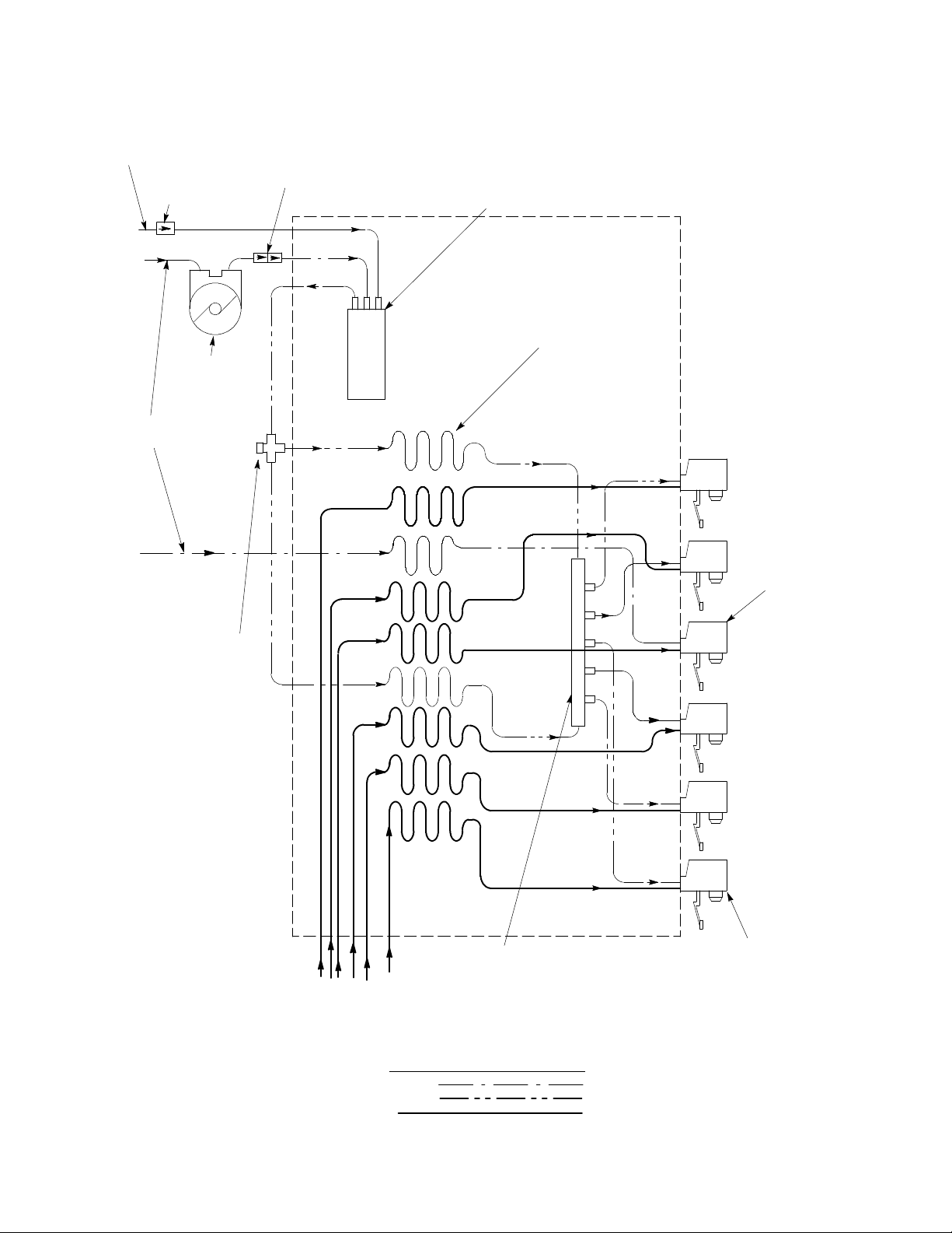
REGULATED
CO2 SUPPLY
CO2 CHECK
VALVE
PLAIN
WATER
WATER
PUMP
DOUBLE LIQUID
CHECK VALVE
BUILT--IN
CARBONAT OR
COOLING
COILS (9)
1
2
NON--CARBONATED
DRINK
CAPPED
CROSS
FITTING
DISPENSER
SYRUP SUPPLY
(SYRUP TANKS OR -
BAG-IN-BOX SYSTEM)
LINE LEGEND
CO2
PLAIN WATER
CARB WATER
SYRUP
CARBONATEDWATER
MANIFOLD
3
4
5
6
DISPENSING VALVE (6)
FIGURE 3. FLOW DIAGRAM
9
318832000
Page 11

 Loading...