

Page 1
®
C10/C20
PM R45,R70 Issue 4 3/99
OVERCOUNTER DISPENSE UNITS
PRODUCT MANUAL
Page 2

1
®
C10/C20 Manual
CONTENTS
1. Introduction...................................................................................................................................2
2. User Instructions
2.1 Operation of the Cooler ..........................................................................................................2
2.2 Cleaning Routing ....................................................................................................................2
3. Specification .................................................................................................................................3
4. Installation.....................................................................................................................................3
5. Maintenance.................................................................................................................................. 4
6. Fault Finding................................................................................................................................. 5
7. C10 (48 1180 1XX/48 1180 2XX) Exploded View ......................................................................6
8. C10 (48 1180 1XX/48 1180 2XX) Spare Parts List......................................................................7
9. C10 (48 1180 3XX/48 1180 4XX) Exploded View ......................................................................8
10. C10 (48 1180 3XX/48 1180 4XX) Spare Parts List......................................................................9
11. C20 (06 1 050101/102/201) Exploded View .............................................................................. 10
12. C20 (06 1 050101/102/201) Spare Parts List.............................................................................. 11
13. C20 (06 1 050103) Exploded View............................................................................................. 12
14. C20 (06 1 050103) Spare Parts List............................................................................................ 13
15. C10 (48 1180 1XX/48 1180 2XX) Wiring Diagram ................................................................... 14
16. C10 (48 1180 3XX/48 1180 4XX) Wiring Diagram ................................................................... 14
17. C20 (06 1 0501XX) Wiring Diagram .........................................................................................15
18. C20 (06 1 0502XX) Wiring Diagram .........................................................................................15
Page 3

2
®
C10/C20 Manual
1. INTRODUCTION
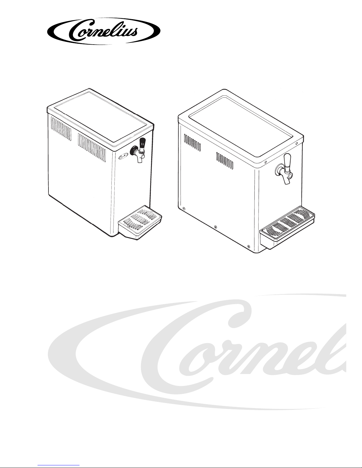
The C10 and C20 are a family of over-counter beer coolers designed to be sited on the counter. An
agitator provides constant agitation of the water bath.
These units are available for 230v 50/60Hz or 115v 60Hz supply voltages.
The cooler has been designed with simplicity and reliability in mind.
The C10 cooler will produce a nominal 7kg of ice.
The C20 cooler will produce a nominal 11kg of ice.
A full Product data sheet is available detailing the technical specification and range of cooler models.
2. USER INSTRUCTIONS
2.1 OPERATION OF THE COOLER
To maintain the safe operation and reliability of the cooler during normal use, please observe the
following points:-
The cooler is designed to run continuously. During normal use it should only be switched off when
cooling will not be required for a period longer than 24 hours. The cooler should be re-started at least
5 hours (dependent on model) before it is to be used.
Do not spill or let liquids drip on the cooler – if liquids do spill onto the unit, electrically isolate before
wiping the spillages up.
Do not place items close the the cooler as this can reduce the air flow to and reliability of the cooler.
Do not place items on top of the cooler as this may cause damage to the agitator/pump assemblies.
Do not move the unit once full of water.
Do not block the water tank overflow tube – any condensation generated by the cooler must be allowed
to run away.
Note: In the event of malfunction switch of f and electrically unplug the cooler . Always use a qualified
Service Engineer to repair the unit – there are no user serviceable components.
2.2 CLEANING ROUTINE
Product coils can be internally cleaned as follows:-
1. Purge the product lines with clean, cool water.
2. Add a chlorinated alkaline cleaning solution, diluted with the correct amount of water, to the
system.
3. Allow to stand in the pipes for the time specified by the cleaning solution manufacturer – usually
30 minutes.
4. Flush the system with clean, cool water to remove all traces of the cleaning solution.
5. Refill the system with the product.
The outside of the cooler can be cleaned using a mild non-foaming aerosol cleaner sprayed onto a dry
soft cloth and wiped over the surface of the cooler. Electrically unplug the unit whilst cleaning.
Page 4

3
®
C10/C20 Manual
3. SPECIFICATION
For a full and detailed specification refer to the product data sheet.
DIMENSIONS C10 C20
Height (nominal): 465mm 500mm
Height (inc tap): 500mm
Width: 275mm 375mm
Depth (nominal): 460mm 585mm
Depth (inc drip tray): 580mm 705mm
Weight (operating): 41kg 60kg
Water bath capacity: 14 litres 24 litres
PERFORMANCE
Ice bank weight 7 kg 11kg
Electrical: See rating plate located on the cooler (or product data sheet) for the electrical rating of this
cooler.
4. INSTALLATION
Installation to be carried out by a suitably trained person only. Compliance with local Bylaws and
Codes of Practise must be ensured.
To ensure trouble free operation it is essential that the unit is installed correctly and sanitised prior to use.
1. The cooler should be sited on a firm level surface, in a well ventilated position, and at a maximum
distance of 2 meters from an electrical supply. To ensure efficient and reliable operation of the
refrigeration system allow 75mm clearance around the unit and that there is an un-impeded flow
of air to and from the condenser grilles. Allow for future access to the lid and service panels.
2. If not already fitted, fit the appropriate electrical plug to the service cord. Consult local Electrical
legislation for correct method of Installation.
WARNING - THIS APPLIANCE MUST BE EARTHED
Do not connect the cooler at this point.
3. Remove the lid and filler cap (as appropriate) and fill the bath with cool, clean, water until the
water flows from the overflow into drip tray. Do not use de-ionised w ater or ad d any substance
to the water . Do not leav e hose pipes unattended whilst filling the w ater bath – the overflow will
not remove water quickly enough. Once filled with water do not move the unit.
4. Ensure that all covers and access panels are screwed in place.
5. Ensure that the cooler is electrically safe. The cooler may now be electrically switched on to
allow it to cool whilst the rest of the Installation is completed.
The cooler will displace water through the overflow as it forms its ice.
6. Electrically isolate the cooler . Connect the beer inlet line and check for leaks before completing
the installation.
7. Sanitise the unit – see User instructions.
8. Electrically switch the unit on.
9. The system is now ready for operation but will not give best results until the ice bank is fully formed.
Page 5

4
®
C10/C20 Manual
5. MAINTENANCE
Maintenance to be carried out by a suitably trained person only. Compliance with local Bylaws and
Codes of Practise must be ensured.
The cooler requires occasional checking and cleaning as follows-
1. Check that the water level in the tank is up to the o verflo w . Remo ve the inspection/f ill cov er and
observe the water level.
2. Check that the airflow to the cooler is unimpeded and clean the condenser fins. To clean the fins
– electrically isolate the unit, use a soft bristle brush to clean the condenser fins of dirt, dust etc.
Take care not to damage the fins during cleaning.
At regular intervals to be determined by the user and/or o wner of the cooler, check for electrical safety.
If any maintenance/servicing is required, refer to the fault finding chart, wiring diagram and exploded
drawings contained in this manual and always ensure that the following are observedWhen replacing components always use IMI Cornelius approved spare parts. Failure to do so will
invalidate the coolers warranty.
Always electrically isolate the cooler before removing covers or carrying out any work.
After working on the cooler ensure that the unit is left electrically safe and that all covers and cover
fixings are refitted.
If replacing a condenser fan motor always fit a new fan blade.
The drier must be replaced each time the refrigeration system is opened.
Always replace seals, screws covers etc. after servicing the cooler.
Page 6
5
®
C10/C20 Manual
6. FAULT FINDING
PROBLEM POSSIBLE FAULT POSSIBLE CAUSE ACTION
Product frozen in Ice bank too large Faulty thermostat Replace
coil Poorly positioned thermostat phial Reposition
Product warm Reduced ice Faulty thermostat Replace
weight or long Fuse blown Check and replace
time to form ice No electrical supply Check
Refrigeration system failure Replace unit
Poor condenser cooling Check clearance
around cooler and
fan motor operation
Check clearance
around cooler and
fan motor operation.
Check condenser and
and clean if necessary
Insufficient water in tank Top up water level
Product too warm Keg badly positioned Reposition keg
into cooler
Poor agitation of water Motor failure Replace motor
onto coils
Pump impeller failed Replace
Excessive algae growth in bath Clean bath and coil
outer surface
Poor system installation Poor airflow to condenser Re-site cooler
Note: Refrigeration system failure could be - Start device for compressor failed, over temperature device in compressor
tripped, open circuit on compressor motor windings, refrigerant gas leak, capillary tube blockage etc. These
faults are best diagnosed and repaired off site in a workshop environment.
Page 7

6
®
C10/C20 Manual
7. C10 (48 1180 1XX/48 1180 2XX) EXPLODED VIEW
13
14
2
3
9
10
11
12
1
4
5
6
7
8
Page 8

7
®
C10/C20 Manual
ITEM
No.
DESCRIPTIONPART No.
1 58 1185 101 Top Cover
2 58 0345 015 Cooling Fan (6mm Bore)
3 13 6690 000 Impellor for Agitator
4 85 6005 818 Cover - Hole
5 80 0800 710 Peardrop Knob Threaded
6a 58 0483 001 Dispense Tap/Faucet
6b 58 0483 002 Dispense Tap BT50
7 58 1185 111 Cup Rest
8 58 1185 102 Drip Tray
9a 44 0000 205 Comp. Set FR7.5G HST
9b 44 0000 240 Comp. Set FF8.5GX HST 115v
10 58 1180 100 Condenser
11 58 1174 007 Thermostat Superspot
12a 58 0410 176 Motor
3
/4" Stack Fan
12b 58 0410 185 Motor 3/4" Stack 115v Fan
13 58 0431 018 Fan Blade 5" O/D CCWSE
14a 99 1180 110 Agitator Motor Assy.
14b 99 1180 113 Agit Motor Assy 115v
14c 58 1170 051 Pump Assy (No. 2)
Not 99 0420 058 Start Relay (240v)
Shown
Not 99 0420 059 Start Capacitor (240v)
Shown
Not 99 0900 002 Compressor Fixing Assy.
Shown
Not 58 1184 101 Mod to Mains Lead
Shown
8. C10 (48 1180 1XX/48 1180 2XX) SPARE PARTS LIST
Page 9

8
®
C10/C20 Manual
1
2
3
4
5
6
7
9
10
11
12
13
14
9. C10 (48 1180 3XX/48 1180 4XX) EXPLODED VIEW
8
Page 10

9
®
C10/C20 Manual
ITEM
No.
DESCRIPTIONPART No.
1 58 1185 101 Top Cover
2 58 0435 015 Cooling Fan (6mm Bore)
3 13 6690 000 Impellor for Agitator
4 85 6005 818 Cover - Hole
5 80 0800 710 Peardrop Knob Threaded (301/6/7)
6a 58 0483 002 Dispense Tap BT50
6b 14 5225 201 Faucet for C-10 Cooler
6c 84 4206 111 Dalex 200 NFCF DH PN C10
7 58 1185 111 Cup Rest
8 58 1185 102 Drip Tray
9a 44 0000 205 Comp. Set FR7.5G HST
9b 44 0000 240 Comp. Set FF8.5GX HST 115v
10 58 1180 123 Condenser STFT 12218
11a 58 0410 187 Fan Motor 5W 230V M/TEK CCWSE
11b 58 0410 190 Fan Motor 5W 115V M/TEK CCWSE
12 44 0000 052 Fan Blade O/D 165mm 26" CCWSE SUCK
13 58 1174 007 Thermostat Superspot
14a 99 1180 126 Agit Motor Assy.
3
/4" Stack Gain
14b 99 2ZU618A No. 2 Pump Assy. EBM (306 only)
14c 06 0 050114 Agit. Mtr. Assy. 3/4" Stack 115v
Not 99 0420 058 Start Relay (240v)
Shown
Not 99 0420 059 Start Capacitor (240v)
Shown
Not 99 0900 002 Compressor Fixing Assy
Shown
Not 58 1184 101 Mod to Mains Lead
Shown
10. C10 (48 1180 3XX/48 1180 4XX) SPARE PARTS LIST
Page 11

10
®
C10/C20 Manual
1
2
3
4
5
6
7
8
9
10
11
12
13
14
11. C20 (06 1 050101/102/201) EXPLODED VIEW
Page 12

11
®
C10/C20 Manual
ITEM
No.
DESCRIPTIONPART No.
1 06 0 055104 Top Cover
2 58 0435 018 Cooling Fan
3 13 6690 000 Impellor for Agitator
4 85 6005 818 Cover - Hole
5 80 0800 710 Peardrop Knob Threaded
6a 14 5225 201 Faucet
6b 58 0483 002 Dispense Tap BT50
7 58 1185 111 Cup Rest
8 58 1185 102 Drip Tray
9a 58 0900 951 Comp. Set SC10GX HST
9b 14 3627 115 Comp. Set FF10GX HST (115v)
10 14 3297 000 Condenser
11 58 0431 015 Fan Blade 8"x30° CW
12a 58 0410 188 Fan Motor 11W 230V M/TEK CCWSE
12b 58 0410 191 Fan Mtr. 10W 115V60HZ M/TEK CCWSE
13 58 1174 007 Thermostat Superspot
14a 99 1180 126 Agit Motor Assy.
3
/4" Stack Gain
14b 06 0 050114 Agit. Mtr. Assy. 3/4" Stack 115v
Not 99 0900 002 Compressor Fixing Assy
Shown
12. C20 (06 1 050101/102/201) SPARE PARTS LIST
Page 13

12
®
C10/C20 Manual
1
2
3
4
5
6
7
8
9
10
11
12
13
14
13. C20 (06 1 050103) EXPLODED VIEW
Page 14

13
®
C10/C20 Manual
ITEM
No.
DESCRIPTIONPART No.
1 06 0 055104 Top Cover
2 58 0435 018 Cooling Fan
3 03 1BF0 33A No. 62 Propellor 66mm DIA (103)
4 85 6005 818 Cover - Hole
5 80 0800 710 Peardrop Knob Threaded
6 84 4206 111 Dalex 200 NFCF 3/8 DH PN C10
7 58 1185 111 Cup Rest
8 58 1185 102 Drip Tray
9 58 0900 951 Comp. Set SC10GX HST
10 14 3297 000 Condenser
11 58 0431 015 Fan Blade 8"x30° CW
12 58 0410 188 Fan Motor 11W 230V M/TEK CCWSE
13 58 1174 007 Thermostat Superspot
14 58 1180 135 Agit. Motor Assy.
3
/4" Stack Gain (103)
Not 99 0900 002 Compressor Fixing Assy
Shown
14. C20 (06 1 050103) SPARE PARTS LIST
Page 15

14
®
C10/C20 Manual
15. C10 (48 1180 1XX/48 1180 2XX) WIRING DIAGRAM
16. C10 (48 1180 3XX/48 1180 4XX) WIRING DIAGRAM
Page 16

15
®
C10/C20 Manual
17. C20 (06 1 0501XX) WIRING DIAGRAM
18. C20 (06 1 0502XX) WIRING DIAGRAM
Page 17

IMI CORNELIUS
UK LTD
Tything Road
Alcester
W arwickshire B49 6EU
Tel: (44) 1789 763 101
Fax: (44) 1789 763 644
IMI CORNELIUS
BENELUX N.V.
Boskapellei 122
B-2930 Brasschaat, Belgium
Tel: (32) 3 660 1020
Fax: (32) 3 660 1045
IMI CORNELIUS
DEUTSCHLAND GmbH
Carl Leverkus Strasse 15
D-40764 Langenfeld, Germany
Tel: (49) 2173 7930
Fax: (49) 2173 77 438
IMI CORNELIUS
FRANCE
35/37 Avenue du Gros Chene
F-95220 Herblay, France
Tel: (33) 1 3440 1580
Fax: (33) 1 3440 1581
IMI CORNELIUS
OSTERREICH
Ges.m.b.H
am Langen Felde 32
A-1222 Vienna, Austria
Tel: (43) 1 203 35200
Fax: (43) 1 204 4474
IMI CORNELIUS
HELLAS S.A.
55 Theomitoros
Allmos 174 55
Athens, Greece
Tel: (30) 1 985 3800
Fax: (30) 1 985 3801
IMI CORNELIUS
ITALIA
SRL
Via Belvedere 26
I-20043 Arcore, Italy
Tel: (39) 039 627 081
Fax: (39) 039 601 3884
IMI CORNELIUS
BRAZIL LTDA.
Rua Itaocara, 97 - CEP 21381-230
Rio de Janiero, RJ - Brazil
Tel: 55-21-596-9595
Fax: 55-21-593-1759
IMI CORNELIUS INC.
One Cornelius Place
Highway 10 West
Anoka, Minnesota 55303-6234
U.S.A.
Tel: (612) 421 6120
Fax: (612) 422 3255
IMI CORNELIUS INC.
3170 Orlando Drive, Unit 3
Mississauga, Ontario L4V 1R5
Canada
Tel: (905) 673 6653
Fax: (905) 673 2830
IMI CORNELIUS
AUSTRALIA PTY. LTD.
144 Milperra Road
Revesby
NSW 2212, Australia
Tel: (61) 2 9774 4533
Fax: (61) 2 9774 5825
IMI CORNELIUS
NEW ZEALAND LTD.
20 Lansford Crescent
P.O. Box 19 044
Av ondale, Auckland 7
New Zealand
Tel: (64) 9 820 0357
Fax: (64) 9 820 0361
IMI CORNELIUS
(SINGAPORE) PTE LTD.
16 Tuas Street
Singapore 638453, Singapore
Tel: (65) 862 5542
Fax: (65) 862 5604
IMI CORNELIUS
PACIFIC LTD.
15th Floor, Hale Weal Industrial Bldg.
22-28 Tai Chung Road
Tsuen W an, N.T.
Hong Kong
Tel: (852) 2789 9882
Fax: (852) 2391 6222
IMI CORNELIUS
ESPANA S.A.
Poligono Industrial, Riera del Fonollar
Sant Boi de Llobregat
E-08830 Barcelona, Spain
Tel: (34) 93 640 2839
Fax: (34) 93 654 3379
 Loading...