

Page 1
BRIX Valve Replacement Kit Installation Instructions
!
WARNING:
!
WARNING:
!
WARNING:
!
CAUTION:
INSTALLATION MANUAL
VIPER BRIX VALVE INSTALLATION INSTRUCTIONS (KIT P/N 629097033)
S
AFETY:
Before starting the installation read and understand all safety labels and warnings on the machine. Also review
and understand all safety instructions in the owners, installation and service manuals. Failure to comply could
result in serious injury, death or damage to the equipment.
QUALIFIED SERVICE PERSONNEL
Only trained and certified electrical, plumbing and refrigeration technicians should service this unit. ALL WIRING
AND PLUMBING MUST CONFORM TO NATIONAL AND LOCAL CODES. FAILURE TO COMPLY COULD
RESULT IN SERIOUS INJURY, DEATH OR EQUIPMENT DAMAGE.
SAFETY PRECAUTIONS
This unit has been specifically designed to provide protection against personal injury. To ensure continued
protection observe the following:
Disconnect power to the unit before servicing following all lock out/tag out procedures established by the user.
Verify all of the power is off to the unit before any work is performed.
Failure to disconnect the power could result in serious injury, death or equipment damage.
Always be sure to keep area around the unit clean and free of clutter. Failure to keep this area clean may result in
injury or equipment damage.
INSTALLATION:
1. Remove splash panel, side panels and rear
panel from the unit.
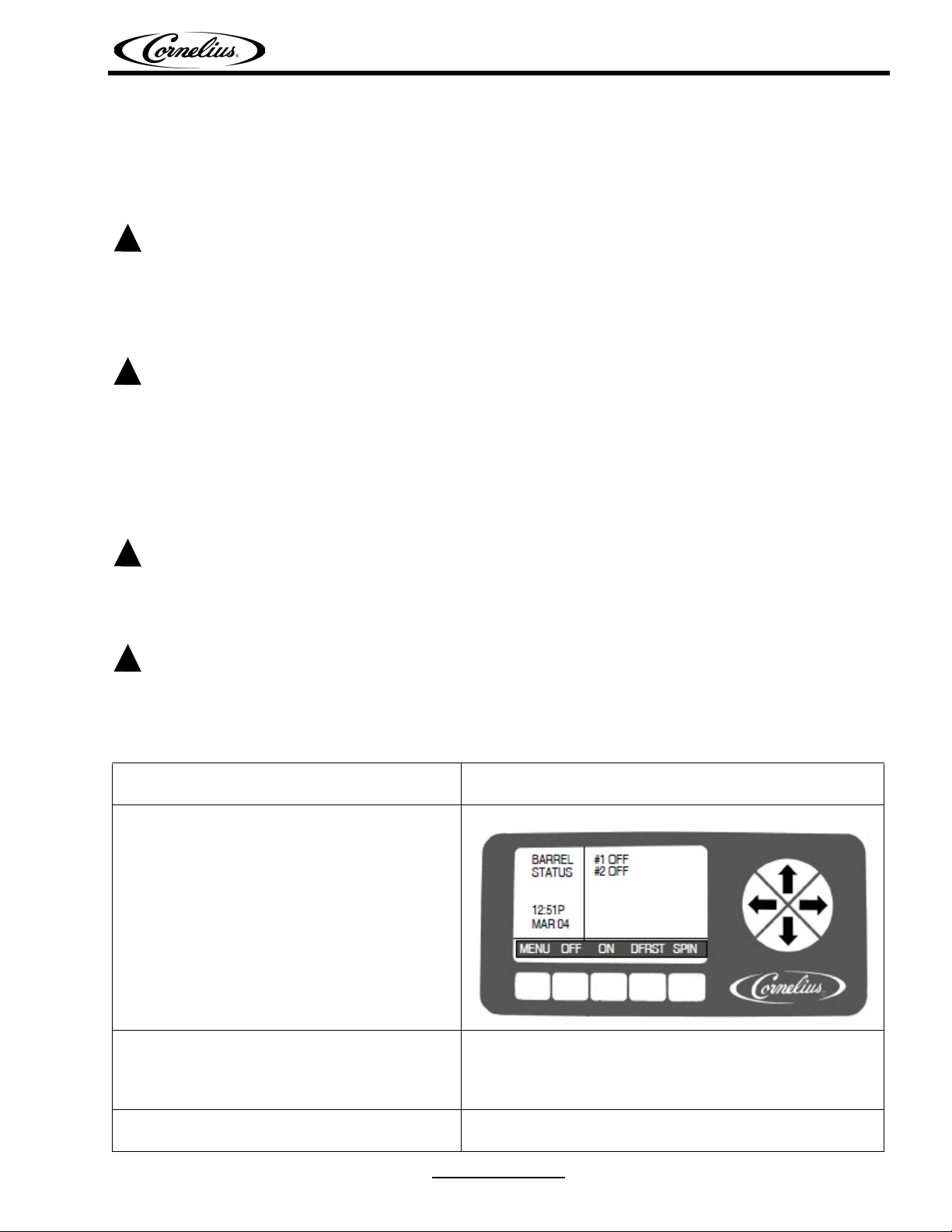
2. Using the control panel, turn the barrels to
the Off position, as shown.
3. Manually defrost each barrel, using the
manual defrost cycle. Refer to the Viper
Service manual (p/n 621260373SER) for
details.
4. Shut off the unit and disconnect it from the
power source.
Revision Date: April 28, 2014 www.cornelius.com R evi si on: C
© 2010-2014, Cornelius Inc. - 1 - Publication Number: 629097033INS
Page 2
BRIX Valve Replacement Kit Installation Instructions
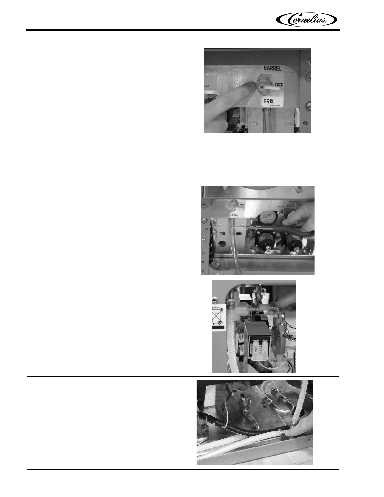
5. Turn the leaking BRIX valve to the center
(Off) position.
6. Purge the barrel associated with the leaking
BRIX valve. Refer to the Viper Service
manual (p/n 621260373SER) for details.
Capture the product from the barrel and
dispose of it properly.
7. When all pressure is relieved from the barrel,
cut off the BRIX tube about 1/2 in. below the
Oetiker clamp. Save the BRIX tube for
reinstallation on the new valve.
8. Remove the two Oetiker clamps at the Yfitting and cut the short piece of tubing with a
utility knife.
9. Remove the two Oetiker clamps at the
product/CO
2 mixing tee and cut the tubing
with a utility knife.
Publication Number: 629097033INS - 2 - © 2010-2014, Cornelius Inc.
Page 3

BRIX Valve Replacement Kit Installation Instructions
BRIX Tube
10. Remove the nut from the front of the BRIX
valve and save it for use when installing the
new valve.
11. Remove the BRIX valve and tubing assembly
through the rear of the panel
12. Attach the BRIX tube to the new BRIX valve
using 2x #12.3 Oetiker clamps, included with
kit p/n 629097033
13. Insert the L-fitting into the top of the BRIX
valve.
© 2010-2014, Cornelius Inc. - 3 - Publication Number: 629097033INS
Page 4

BRIX Valve Replacement Kit Installation Instructions
OFF
OFF
14. Finish assembling the new replacement
BRIX valve by attaching the short piece of
tubing to the Y-fitting using 2x#11.3 Oetiker
clamps.
15. Secure the complete BRIX valve assembly to
the sheet metal bracket with the nut.
16. Attach the pre-formed kit tubing to the
product/CO
2 mixing tee using 2x#11.3
Oetiker clamps.
17. Reconnect power to the unit, the menu
screen displays the barrel status in the Off
position.
Publication Number: 629097033INS - 4 - © 2010-2014, Cornelius Inc.
Page 5

BRIX Valve Replacement Kit Installation Instructions
FILL
FILL
18. Press the Menu button and select the MAINT
menu, then Select the Barrel Maint option.
Make sure BRIX valve is in the Barrel
position.
19. When the Barrel Maint menu opens, select
the FILL button on the control panel. Refer to
the Viper Service manual (p/n
621260373SER) for details.
20. Check the new connections for leaks.
21. Press the BACK button to return to the Main
screen and press the ON button to place the
unit in Freeze mode. The unit should operate
normally.
22. Replace the splash panel, side panels and
rear panel to the unit.
© 2010-2014, Cornelius Inc. - 5 - Publication Number: 629097033INS
 Loading...