


INSTRUCTION
MANUAL
Part # 702900
TITAN
1075 RollbagTM
“The Single source for all your packaging needs”
©2003
1533 Crescent Dr • Carrollton, TX 75006 • Phone: 972.389.0777 • Fax: 800.875.5528 • www. audionautomation.com

TABLE OF CONTENTS
Page2
1533 Crescent Dr • Carrollton, TX 75006 • Phone: 972.389.0777 • Fax: 800.875.5528 • www. audionautomation.com
HOW TO USE THIS MANUAL
NOTES
This users manual contains information important to the proper operation of the 1075 Rollbag Packaging system.
SAFETY INFORMATION
This manual also contains very important information to protect both the operator and the machine. Please pay special attention to the SAFETY WARNINGS that appear in the manual.
The STOP icon appearing in the margin alerts you to a safety warning on the subject it accompanies.
A CAUTION icon alerts you to the possibility of an event that may affect the machine and its operation. A full explanation of the safety caution accompanies the caution icon when it is used.
READ MANUAL FIRST
Your new TITAN 1075 Rollbag packaging machine is safe and easy to use and maintain providing a few simple procedures are followed.
IMPORTANT: PLEASE READ THIS MANUAL AND FAMILIARIZE YOURSELF WITH THE EQUIPMENT BEFORE ATTEMPTING TO USE IT. THE MANUAL WILL SERVE AS A VALUABLE AID TO UNDERSTANDING THE MACHINE, ITS OPERATION, AND THE PACKAGING MATERIALS USED WITH IT.
As Audion Automation’s policy is one of continuous improvement and development of each line of machinery that we make, this manual though up to date at the time of publication is subject to change without notice.
Serial number ______________ and voltage marked on the ID plate _______VAC
Please enter the serial number of your machine in the space provided above. If it becomes necessary to contact Audion Automation, please be prepared to furnish both the model number and serial number.
Page3
1533 Crescent Dr • Carrollton, TX 75006 • Phone: 972.389.0777 • Fax: 800.875.5528 • www. audionautomation.com
SAFETY INFORMATION
FOLLOW LOCAL ELECTRICAL AND SAFETY CODES AS WELL AS THE NATIONAL ELECTRICAL CODE (NEC) AND THE OCCUPATIONAL HEALTH AND SAFETY ACT (OSHA).
POWER
The unit must be located at or near an appropriate electrical supply. Be certain that the power source conforms to the requirements of the machine and that the proper gauge and type of wire is used. Connections should be made using the shortest possible runs of wire. Long runs of wire can result in reduced voltage.
Check the specifications on the Machine Identification Label, if the Machinery is rated at 120 volts AC, it may be plugged directly into an appropriately grounded electrical supply. The use of extension cords is not recommended. Units that are marked for voltages of 208 volt AC and above should only be installed by a qualified electrician.
ALL WARRANTIES ARE VOID IF THE MACHINE IS USED WITH AN IMPROPER GROUND OR IN AN UNGROUNDED CONDITION.
ONLY QUALIFIED SERVICE PERSONS SHOULD BE ALLOWED TO SERVICE THE EQUIPMENT. THEY MUST BE EQUIPPED WITH PROPER TOOLS AND HAVE AN ELECTRICAL SCHEMATIC OF THE UNIT.
There are live, high voltage components within the machine. Always disconnect the machine from its power source and secure using approved LOCK OUT - TAG OUT procedures as specified by OSHA before removing any access panels or attempting to service the machine. On machines intended for 110-125 volt AC service disconnect the line cord and secure the male plug in an approved LOCK OUT - TAG OUT device to prevent an
unexpected reapplication of electrical service. Machines marked for 208 volts AC and higher must be disconnected from electrical service via removal of fuses at the supply, switching its disconnect to the OFF position and locking the switch lever and tagging it so that there can not be an unexpected reapplications of electrical service. Only a qualified electrician should perform these tasks.
DO NOT OPERATE THIS UNIT IN AN EXPLOSIVE ATMOSPHERE. DO NOT SUBJECT THE MACHINE TO WET OR CORROSIVE ENVIRONMENTS. KEEP ALL FLAMMABLE AND CAUSTIC SUBSTANCES AWAY FROM THE MACHINE AT ALL TIMES.
LOCATION
The unit must be located indoors only, in a nonexplosive atmosphere. Place the unit on a level, sturdy table that as a minimum is able to support the weight of the machine and the products that are to be packaged as well as those that have been packaged.
Page4
1533 Crescent Dr • Carrollton, TX 75006 • Phone: 972.389.0777 • Fax: 800.875.5528 • www. audionautomation.com

INSTALLATION AND SETUP
1.Check shipping packaging for signs of damage. If there are any signs of mishandling, it is a good idea to take pictures of the damaged container before the machine is removed from it. Remove the machine and check it for damages. You will need to immediately notify your shipping carrier if damages are found.
Damages will have to be accounted for by the carrier not Audion Automation!
2.Place the machine on a worktable. Level the machine by adjusting the four feet on the bottom of the machine. All four feet must be touching the tabletop!
See figure 1.
3.Install the Roll Bag support brackets onto the backside of the machine.
See figures 4 & 7.
Back out the two screws enough to allow the slots in the brackets to
slide over the screws. Seat the bracket and securely tighten the screws. The left bracket contains a filter regulator unit. Connect the air line to the bulkhead fitting on the backside of the machine.
See figure 6.
4.Install the Power and Foot Switch cords into their corresponding receptacles on the backside of the machine. Plug the power cord into a 120vac, 3-amp (min.) circuit.
See figure 6.
5.Connect a dry air supply of at least 80 psi to the regulator. Adjust the regulator for an 80-psi output. CAUTION: THE SEAL JAW WILL SWING OPEN.
See figure 1.
6.Turn the machine on. The On/Off switch is part of the Power Entry Module located on the backside of the machine. (See figure 6). The display on the PLC will flash the seal bar temperature set point value until the temperature is reached. The PLC will then put the machine in "Manual Mode".
7.Reset Emergency Stop. Rotate red knob of switch clockwise.
See figure 1.
8.Place a roll of bags onto the support rod. Install a spring and a retainer on either side of the roll. Place this unit on the support brackets making sure the flats on the rod are securely seated in the bracket slots. Center the roll to the machine. Create a light antiroll tension on the roll by slightly compressing the springs as you lock the retainers into position.
See figures 4 & 5.
Page5
1533 Crescent Dr • Carrollton, TX 75006 • Phone: 972.389.0777 • Fax: 800.875.5528 • www. audionautomation.com
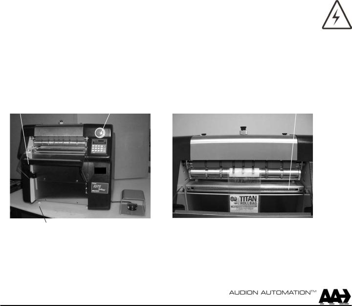
9. Thread the bag stream into the machine. First open the Pinch Roller by moving its toggle switch to the open position (to the left it you are at the back of the machine).
See figure 3.
The Pinch Roller will drop down creating a gap between itself and the Drive Roller. Lift the Bag Perf Sensor (center black knob) and rotate it ¼ turn clockwise and then release it.
See figure 3.
It will now be setting on a ledge that will keep it suspended above the platen. Unwind approximately two feet of bags from the roll and thread the bag stream between the plate and Perf Sensor and then between the Drive and Pinch rollers. Pull the bag stream down until a perforation line is near the top of the Stripper bracket.
See figure 2.
Now close the Pinch roller by moving the toggle switch back to the right. Reset the Bag Perf Sensor by rotating it counterclockwise and allowing the spring pressure to push it down to the platen. Ensure proper seating by lifting and releasing the sensor a few times.
10.The bag is opened at the end of the seal cycle by a high volume stream of air. After the bag is opened the high volume air is turned off and a low volume air supply is turned on. The low volume air will maintain the bag opening without wasting a lot of air. The two air supplies are adjustable. The flow controls are located on the backside of the machine. Adjust to suit your needs.
See figure 7.
11.The machine is now ready for operation. Read the "Machine Operation" section of this manual before attempting to run the machine!
|
|
|
Stripper BRKT |
|
E-Stop |
||||
Seal Jaw |
Fig. 1 |
Levelling Foot |
Fig. 2 |
Page6
1533 Crescent Dr • Carrollton, TX 75006 • Phone: 972.389.0777 • Fax: 800.875.5528 • www. audionautomation.com

MACHINE SET - UP
Pinch Roller
Toggle Shut Off
Bag PKAF |
Support |
Brackets |
Bag Roll
Support Rod
Fig. 3 |
Fig. 4 |
Retainer |
Spring |
On/Off Switch
Flow
Controls
Air Fitting
Fig. 5 |
Central |
Fig. 6 |
Power |
Foot Switch |
|
|
|
|
|
|
Bag Roll |
|
|
|
Bag Roll
Support
BRKT
High
Volume
Constant Low
Volume
Fig. 7
Page7
1533 Crescent Dr • Carrollton, TX 75006 • Phone: 972.389.0777 • Fax: 800.875.5528 • www. audionautomation.com

MACHINE OPERATION
The 1075 Rollbag Packaging System automatically dispenses, opens for filling and seals preopened perforated bags on a roll. The basic machine operation requires product to be placed into the opened bag upon which a seal cycle is initiated. The seal jaw closes, capturing the bag between the seal pad and the seal bar. The temperature controlled constant heat seal bar welds the front and back faces of the bag together. After the sealing process is completed, a parting blade is extended to separate the sealed bag from the bag stream. As the seal jaw opens, the sealed bag drops out of the way and a new bag is fed into the fill position. The bag is opened with a burst of high volume air as it reaches the fill position. The bag opening is maintained by a supply of low volume air. The machine is ready for the next seal cycle.
Note: For safety reasons, the jaw closes under a two-pressure system. The jaw closes under low pressure until it is almost closed, less than ¼" travel left. At this point high pressure finishes the closing of the jaw. The jaw remains under high pressure throughout the sealing process. The jaw opens under low pressure. For added safety the jaw close cycle is timed. If the PLC does not receive the jaw close input within a specified time, the jaw is immediately reversed.
The machine has three modes of operation. These modes (Manual, Automatic, Auxiliary) determine how the next seal cycle is initiated.
In Manual Mode the foot switch initiates the cycle. The operator depresses and then releases the foot switch to run a single cycle. If the operator keeps the foot switch depressed, the machine will keep running cycles. By releasing the foot switch the machine will stop after the present cycle is completed.
In Automatic Mode the machine will run cycles based on an operator predetermined pace rate. Depressing and releasing the foot switch will cause the automatic cycles to start processing. Cycles will run at the predetermined rate until the foot switch is depressed again or the machine is put in manual mode. The pace rate will depend on the time required for the operator to fill the bag. Pace rate is adjustable through the operator panel on the PLC.
In Auxiliary Mode the machine is interfaced with external automatic filling and feeding equipment. The machine is capable of sending and receiving electrical signals to control the external feeding and delivery systems. The inputs from these devices will determine how cycles are run.
The 1075 Rollbag machine has adjustable parameters so one can fine-tune the operation of the machine. Once the parameters have been defined for a particular type of bag or process they can be saved as a program. The next time that particular setup is required all one has to do is call up the program associated to it. Multiple programs can be stored on the PLC. The values of the parameters are changed through the front panel of the PLC. The following list contains a brief description of each adjustable parameter.
Page8
1533 Crescent Dr • Carrollton, TX 75006 • Phone: 972.389.0777 • Fax: 800.875.5528 • www. audionautomation.com

MACHINE OPERATION (cont.)
Seal Time is the amount of time the seal jaw stays closed against the seal bar during a seal cycle. The jaw close time will depend on the type of material the bag is made of and its thickness. In general, the thicker the bag the more time it takes to seal it.
Start Delay parameter determines the cycle pace rate when running in Automatic Mode. This time is determined by the amount of time required by the operator to fill the bag. This parameter is also used to delay cycle start when running off a photo eye system or an external cycle start system.
Bag Stop Position controls the length of time the bag feed motor runs after the PLC receives an input from the Bag Perf Sensor. The run time determines where the top of the bag stops in relation to the sea bar. To raise the bag one must decrease the value of the parameter.
Cycles to Run is a cycle counter. Its value will determine the number of cycles the machine will run before it sets a warning flag. The PLC will display "Count Target" when the number of cycles ran matches the preset value. The current cycle count is displayed on the PLC along side "Manual Mode" or "Automatic Mode". Pressing the "zero" button on the PLC resets the current cycle count. When in the chain/strip packaging mode the cycle counter considers the chain as a single cycle. If the chain value is set for three, and six bags are sealed, the counter will show a count of two.
Bags Chain is the number of bags wanted in the chain. When the last bag of the chain is sealed, the parting blade will advance and separate the chain from the roll of bags.
Program Number is the value of the program that is currently being used. Each program can contain a value for each of the adjustable parameters. All values can be different from one program to the next. The operator will need to keep track of which program to run with a particular bag or process.
B.Roll Qty parameter contains the number of bags on a new roll of bags. The operator enters this value when he installs the roll of bags onto the machine. Each cycle will decrement this value. When the bag remaining count reaches 30, the PLC will set a flag. "Bags Low" will be displayed on the PLC.
Air On parameter determines when the high volume air is turned on. This airflow is used to open the bag.
Air Off parameter determines when the high volume air is turned off. On difficult to open bags, the air may need to stay on for a longer period of time.
Feed Delay parameter enables one to delay the bag feed start time from its normal setting. A machine equipped with a printer may need to delay the start of the bag feed cycle.
Temp Set parameter is the set point value for the temperature of the seal bar. The heat required to seal a bag will depend on the bag material and its thickness. Typically a thick bag will require a higher temperature or a higher seal dwell time than a thin bag.
Page9
1533 Crescent Dr • Carrollton, TX 75006 • Phone: 972.389.0777 • Fax: 800.875.5528 • www. audionautomation.com

MACHINE OPERATION (cont.)
Bag Support parameter controls the amount of time the bag support tray (optional) stays in the rotated position. The tray rotates to dump the sealed bag.
Note: Seal bar temperature and seal dwell time will determine the quality of seals one can achieve. Typically one will make adjustments to these two parameters on a trial and error basis until an acceptable seal is accomplished. A good seal will have a milky appearance its entire length and width. A poor seal can be recognized by complete melt thru in areas of the seal zone or the bag is easily opened. Rule of ThumbThick (heavy gage) bags will require a higher temperature and/or more seal time than thin (light gage) ones. A good starting point would be to have the temperature set at 220 degrees Fahrenheit and the seal time set at .6. These settings should be finalized before running production!
Note: Never attempt to heat seal through the printed area of a bag. The ink will transfer onto the seal pad and seal bar causing seal quality problems on subsequent seals
Page10
1533 Crescent Dr • Carrollton, TX 75006 • Phone: 972.389.0777 • Fax: 800.875.5528 • www. audionautomation.com
 Loading...