


Combi steamer
OES OEB OGS OGB /
OES OEB OGS OGB easyTOUCH=
ENG Installation manual
Translation of the original

Table of Contents
Table of Contents
1 |
General information |
4 |
|
|
► |
Environmental protection |
5 |
|
► Identifying your combi steamer |
6 |
|
|
► |
About this installation manual |
9 |
2 |
Layout and function |
11 |
|
|
► Intended use of your combi steamer |
12 |
|
|
► |
Layout and function of the combi steamer (standard controls) |
13 |
|
► |
Layout and function of the combi steamer (easyTOUCH controls) |
16 |
3 |
For your safety |
19 |
|
|
► |
Basic safety code |
20 |
|
► Hazards and safety precautions |
21 |
|
|
► |
Requirements for safe setup, installation and preparation for first-time use |
23 |
►Requirements to be met by personnel, personal protection equipment and working
|
positions |
24 |
|
|
► Warning signs on the combi steamer |
25 |
|
|
► |
Safety devices |
27 |
4 |
Moving and setting up the appliance |
29 |
|
|
► Requirements for the installation location |
30 |
|
|
► Taking to the installation location |
35 |
|
|
► |
Unpacking |
36 |
|
► Setting up table-top appliances |
39 |
|
|
► Setting up floor-standing appliances |
42 |
|
5 |
Connecting up the combi steamer |
44 |
|
|
► |
Electrical installation |
45 |
|
► |
Energy optimization system |
47 |
|
► |
Water supply |
48 |
|
► |
Water drain |
51 |
|
► Making settings in the Service program |
54 |
|
|
► Regulations for installing gas appliances |
56 |
|
|
► |
Approvals |
57 |
|
► Gas installation to a fixed connection on OGS/OGB appliances |
58 |
|
|
► Gas installation for liquid gas bottles on OGS/OGB appliances |
61 |
|
|
► Flue gas removal system for OGS/OGB appliances |
66 |
|
6 |
Preparing for first-time use, taking out of service and |
|
|
|
disposal |
69 |
|
|
► |
Safe working |
70 |
|
► Procedure for preparing the appliance for first-time use |
72 |
|
|
► Taking out of service and disposal |
74 |
|
7 |
Optional equipment and accessories |
75 |
|
|
► CONVOClean automatic interior oven cleaning system |
76 |
|
|
► CONVOVent and CONVOVent Plus extractor hood/condensation hoods |
79 |
|
Installation manual |
2 |

Table of Contents
► |
Stacking kit |
81 |
► |
Grill version |
82 |
► |
Ship model |
84 |
► |
Communications interface |
85 |
8 |
Technical data, dimensional drawings and connection |
|
|
|
diagrams |
86 |
|
8.1 |
Technical data |
87 |
|
|
► Technical data for OES |
88 |
|
|
► Technical data for OEB |
92 |
|
|
► Technical data for OGS |
97 |
|
|
► Technical data for OGB |
102 |
|
|
► Technical data for accessories |
107 |
|
8.2 |
Dimensions, dimensional drawings and connection diagrams |
108 |
|
|
► |
OES/OEB 6.10 |
109 |
|
► |
OES/OEB 6.20 |
110 |
|
► |
OES/OEB 10.10 |
111 |
|
► |
OES/OEB 10.20 |
112 |
|
► |
OES/OEB 12.20 |
113 |
|
► |
OES/OEB 20.10 |
114 |
|
► |
OES/OEB 20.20 |
115 |
|
► |
OGS 6.10 |
116 |
|
► |
OGS 6.20 |
117 |
|
► |
OGS 10.10 |
118 |
|
► |
OGS 10.20 |
119 |
|
► |
OGS 12.20 |
120 |
|
► |
OGS 20.10 |
121 |
|
► |
OGS 20.20 |
122 |
|
► |
OGB 6.10 |
123 |
|
► |
OGB 6.20 |
124 |
|
► |
OGB 10.10 |
125 |
|
► |
OGB 10.20 |
126 |
|
► |
OGB 12.20 |
127 |
|
► |
OGB 20.10 |
128 |
|
► |
OGB 20.20 |
129 |
9 |
Checklists and completion of installation |
130 |
|
► Checklist: Installation |
131 |
|
► Checklist: Safety devices and warnings |
134 |
|
► Checklist: Customer guidance and instruction - safety |
135 |
|
► Checklist: Customer guidance and instruction - operation and maintenance |
140 |
|
► Completion of the installation |
141 |
Installation manual |
3 |

General information
1 General information
Purpose of this chapter
This chapter shows you how to identify your combi steamer and provides guidance on using this manual.
Contents |
|
|
This chapter contains the following topics: |
|
|
|
|
Page |
Environmental protection |
5 |
|
Identifying your combi steamer |
6 |
|
About this installation manual |
9 |
|
Installation manual |
4 |

General information
► Environmental protection
Statement of principles
Our customers' expectations, the legal regulations and standards and our company's own reputation set the quality and service for all our products.
We have an environmental management policy that not only ensures compliance with all environmental regulations and laws, but also commits us to continuous improvement of our green credentials.
We have developed a quality and environmental-management system in order to guarantee the continued manufacture of high-quality products, and to be sure of meeting our environmental targets.
This system satisfies the requirements of ISO 9001:2008 and ISO 14001:2004.
Environmental protection procedures
We observe the following procedures:
Use of residue-free compostable wadding materials
Use of RoHS-compliant products
Multiple re-use of cardboard packaging
Recommendation and use of bio-degradable cleaning agents
Recycling of electronic waste
Environmentally friendly disposal of old appliances via the manufacturer
Join us in a commitment to environmental protection.
Installation manual |
5 |
General information
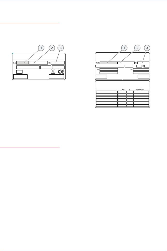
► Identifying your combi steamer
Position and layout of the type plate
You can use the type plate to identify your combi steamer. The type plate is located on the left-hand side of the combi steamer.
The type plate has the following layout on electric appliances:
The type plate has the following layout on gas appliances:
_
The following table lists the relevant items on the type plate:
Item number |
Meaning |
1 |
trade name |
2 |
part number |
3 |
serial number |
Code making up the trade name
On both type plates, the code making up the trade name (1) identifies your appliance:
|
Elements of the trade |
Meaning |
|
name |
|
Letters |
|
|
1. letter |
O = Eco (always present) |
|
|
|
|
2. letter |
E = Electric appliance |
|
|
|
G = Gas appliance |
3. letter |
B = Appliance with steam gen- |
|
|
|
erator |
|
|
S = Appliance with injection |
|
Numerical values |
|
xx.yy |
Appliance size |
|
Installation manual |
6 |

General information
Table-top appliances
Use the table below to identify your table-top appliance from the trade name on the type plate:
Model |
Type |
Number of shelves |
Optional shelves |
|
|
|||||
|
|
|
|
1/1 GN |
|
2/1 GN |
|
600 x 400 baking tray |
|
Number of |
|
|
|
|
|
|
|
|
|
|
plates |
|
|
|
|
|
|
|
|
|
|
|
OES 6.10 |
|
Electric appliance with injection |
|
7 |
- |
|
5 |
|
20 |
|
|
|
|
|
|
|
|
|
|
|
|
OGS 6.10 |
Gas appliance with injection |
7 |
- |
5 |
|
20 |
||||
|
|
Electric appliance with steam |
|
|
|
|
|
|
|
|
OEB 6.10 |
|
|
7 |
- |
|
5 |
|
20 |
||
|
|
generator |
|
|
|
|
|
|
|
|
|
Gas appliance with steam genera- |
|
|
|
|
|
|
|
||
OGB 6.10 |
7 |
- |
|
5 |
|
20 |
||||
|
tor |
|
|
|
|
|
|
|
||
OES 6.20 |
Electric appliance with injection |
14 |
7 |
12 |
42 |
|||||
|
|
|
|
|
|
|
||||
OGS 6.20 |
Gas appliance with injection |
14 |
7 |
12 |
42 |
|||||
|
|
|
|
|
|
|
||||
OEB 6.20 |
Electric appliance with steam |
14 |
7 |
12 |
42 |
|||||
|
generator |
|
|
|
|
|
|
|
||
OGB 6.20 |
Gas appliance with steam genera14 |
7 |
12 |
42 |
||||||
|
tor |
|
|
|
|
|
|
|
||
OES 10.10 |
Electric appliance with injection |
11 |
- |
7 |
|
32 |
||||
|
|
|
|
|
|
|
|
|
|
|
OGS 10.10 |
|
Gas appliance with injection |
|
11 |
- |
|
7 |
|
32 |
|
|
Electric appliance with steam |
|
|
|
|
|
|
|
||
OEB 10.10 |
11 |
- |
|
7 |
|
32 |
||||
|
generator |
|
|
|
|
|
|
|
||
|
|
Gas appliance with steam genera- |
|
|
|
|
|
|
|
|
OGB 10.10 |
|
|
11 |
- |
|
7 |
|
32 |
||
|
tor |
|
|
|
|
|
|
|
|
|
OES 10.20 |
Electric appliance with injection |
22 |
11 |
18 |
63 |
|||||
|
|
|
|
|
|
|
||||
OGS 10.20 |
Gas appliance with injection |
22 |
11 |
18 |
63 |
|||||
|
|
|
|
|
|
|
||||
OEB 10.20 |
Electric appliance with steam |
22 |
11 |
18 |
63 |
|||||
|
generator |
|
|
|
|
|
|
|
||
OGB 10.20 |
Gas appliance with steam genera22 |
11 |
18 |
63 |
||||||
|
tor |
|
|
|
|
|
|
|
||
Installation manual |
7 |

General information
Floor-standing appliances
Use the table below to identify your floor-standing appliance from the trade name on the type plate:
Model |
Type |
Number of shelves |
Optional shelves |
|
|
|
|
1/1 GN |
2/1 GN |
600 x 400 baking tray |
OES 12.20 |
Electric appliance with injection |
24 |
12 |
10 |
|||
|
|
|
|
|
|
|
|
OGS 12.20 |
Gas appliance with injection |
24 |
12 |
10 |
|||
|
|
|
|
|
|
|
|
OEB 12.20 |
Electric appliance with steam |
24 |
12 |
10 |
|||
|
generator |
|
|
|
|
||
OGB 12.20 |
Gas appliance with steam genera24 |
12 |
10 |
||||
|
tor |
|
|
|
|
||
OES 20.10 |
|
Electric appliance with injection |
|
20 |
- |
17 |
|
|
|
|
|
|
|
|
|
OGS 20.10 |
Gas appliance with injection |
20 |
- |
17 |
|||
|
|
Electric appliance with steam |
|
|
|
|
|
OEB 20.10 |
|
|
20 |
- |
17 |
||
|
|
generator |
|
|
|
|
|
|
Gas appliance with steam genera- |
|
|
|
|
||
OGB 20.10 |
20 |
- |
17 |
||||
|
tor |
|
|
|
|
||
OES 20.20 |
Electric appliance with injection |
40 |
20 |
17 |
|||
|
|
|
|
|
|
||
OGS 20.20 |
Gas appliance with injection |
40 |
20 |
17 |
|||
|
|
|
|
|
|
||
OEB 20.20 |
Electric appliance with steam |
40 |
20 |
17 |
|||
|
generator |
|
|
|
|
||
OGB 20.20 |
Gas appliance with steam genera40 |
20 |
17 |
||||
|
tor |
|
|
|
|
||
Number of plates
59 or 74
59 or 74
59 or 74
59 or 74
50 or 61
50 or 61
50 or 61
50 or 61
98 or 122
98 or 122
98 or 122
98 or 122
Installation manual |
8 |

General information
► About this installation manual
Purpose
This installation manual provides answers to the following questions:
How do I set up the combi steamer?
How do I connect up the combi steamer?
How do I prepare the combi steamer for use?
The aim of this installation manual is to show you how to perform the following tasks:
Setting up the appliance.
Connecting the appliance to the electrical supply.
Connecting the appliance to the water supply.
Connecting the appliance to the gas supply.
Connecting the appliance to the flue gas installation.
Preparing the appliance for use.
Who should read this manual
This installation manual is aimed at the following groups:
Personnel |
|
Tasks |
|
Qualifications |
Chapter to read before task |
|
|
|
|
|
|
Equipment mover |
Conveying within the |
Trained in the use of a pallet For your safety on page 19 |
|||
|
|
establishment |
truck and forklift truck |
Moving and setting up the appli- |
|
|
|
|
|
|
|
|
|
|
|
|
ance on page 29 |
|
|
|
|
||
Service engineer |
Setting up the appliance |
Is an employee of an |
Layout and function on page 11 |
||
|
Connecting the appliance |
|
approved customer ser- |
For your safety on page 19 |
|
|
Preparing the appliance |
|
vice unit. |
||
|
|
Moving and setting up the appli- |
|||
|
|
for first-time use |
Has relevant technical |
||
|
|
ance on page 29 |
|||
|
Taking the appliance out |
|
training. |
||
|
|
Connecting up the combi steamer |
|||
|
|
of service |
Is trained in the particular |
||
|
Instructing the user |
|
appliance. |
on page 44 |
|
|
|
|
|
|
Preparing for first-time use, taking |
|
|
|
|
|
out of service and disposal on |
|
|
|
|
|
page 69 |
|
|
|
|
|
Optional equipment on page 75 |
|
|
|
|
||
Gas fitter |
Connecting the applian- |
Is a gas fitter authorized |
Layout and function on page 11 |
||
|
|
ce: gas |
|
by the gas supply com- |
For your safety on page 19 |
|
Isolating the appliance |
|
pany. |
||
|
|
Connecting up the combi steamer |
|||
|
Has relevant professional |
||||
|
|
from the gas supply |
|||
|
|
mains |
|
training. |
on page 44 |
|
|
|
|
||
Electrical fitter |
Connecting the applian- |
Is an employee of an |
Layout and function on page 11 |
||
|
|
ce: electric |
|
approved customer ser- |
For your safety on page 19 |
|
Isolating the appliance |
|
vice unit. |
||
|
|
Connecting up the combi steamer |
|||
|
|
from the electrical supply |
Has relevant professional |
||
|
|
mains |
|
training. |
on page 44 |
Is a qualified electrician.
Documents included in the Customer documentation
The customer documentation for the combi steamer includes the following documents:
Installation manual (this document)
User manual
Help facility included in the software (extracts from the user manual)
Installation manual |
9 |
General information
Chapters in the installation manual
The table below lists the chapters in this manual and summarizes their content and purpose:
Step |
Action |
General information |
Shows you how to identify your combi steamer. |
|
Provides guidance on using this installation manual. |
Layout and function |
Specifies the intended use of the combi steamer. |
|
Explains the functions of the combi steamer and shows the position of its |
|
components. |
For your safety |
Describes the hazards posed by the combi steamer and appropriate preven- |
|
tive measures. |
|
It is important that you read this chapter carefully. |
Moving and setting up the appliance
Specifies the basic appliance dimensions.
Specifies requirements for the installation location.
Provides information on conveying the appliance to the installation location, unpacking and setting up.
Connecting up the combi steamer
Lists necessary approvals.
Provides information on installing the:
electrical supply
gas
water
flue gas
drain
air vent
Preparing for first-time use, |
Explains the procedure for preparing the appliance for first-time use. |
taking out of service and |
Explains the procedure for taking out of service. |
disposal |
Contains disposal instructions. |
Optional equipment |
Describes features of the various optional equipment. |
|
|
Technical data, dimensional |
Contains the technical data and connection diagrams. |
drawings and connection |
|
diagrams |
|
Checklists and completion of installation
Contains the checklists for
Installation
Safety instructions and warnings
Customer guidance and instruction.
Contains information on the warranty and explains the completion procedure using the checklists.
Symbols used for safety instructions
Safety instructions are categorized according to the following hazard levels:
|
Hazard level |
Consequences |
Likelihood |
|
|
Death / serious injury (irreversible) |
Immediate risk |
|
|
|
|
|
|
Death / serious injury (irreversible) |
Potential risk |
|
|
|
|
|
|
Minor injury (reversible) |
Potential risk |
|
|
|
|
|
Caution |
Damage to property |
Potential risk |
|
|
|
|
Installation manual |
10 |

Layout and function
2 Layout and function
Purpose of this chapter
This chapter specifies the intended use of the combi steamer and explains its functions.
Contents |
|
|
This chapter contains the following topics: |
|
|
|
|
Page |
Intended use of your combi steamer |
12 |
|
Layout and function of the combi steamer (standard controls) |
13 |
|
Layout and function of the combi steamer (easyTOUCH controls) |
16 |
|
Installation manual |
11 |

Layout and function
► Intended use of your combi steamer
Intended use
The combi steamer must only be used for the purposes specified below:
The combi steamer is designed and built solely for cooking different foodstuffs. Steam, convection and superheated steam are used for this purpose.
The combi steamer is intended solely for professional, commercial use.
The ambient temperature must lie between 4°C and 35°C.
In addition, the combi steamer is only being used as intended when the following conditions are met:
To avoid accidents and damage to the combi steamer, the owner must train staff regularly. The combi steamer must only be operated by trained staff.
The manufacturer regulations for operation and maintenance of the combi steamer must be observed.
Restrictions on use
The following restrictions on use must be observed:
The combi steamer must not be operated in toxic or potentially explosive atmospheres.
The combi steamer must only be operated at ambient temperatures between +4°C and +35°C.
The combi steamer must only be used by trained personnel.
The combi steamer must be suitably sheltered from the rain and wind if operated outdoors.
The combi steamer must not be loaded over the maximum permissible loading weight for the given model.
The combi steamer must only be operated when all safety devices are fitted and in working order.
Dry powder or granulated material must not be heated in the combi steamer.
Highly flammable objects with a flash point below 270 °C must not be heated in the combi steamer. These include items such as highly flammable oils, fats or cloths (kitchen cloths).
Food in sealed tins or jars must not be heated in the combi steamer.
Installation manual |
12 |
Layout and function
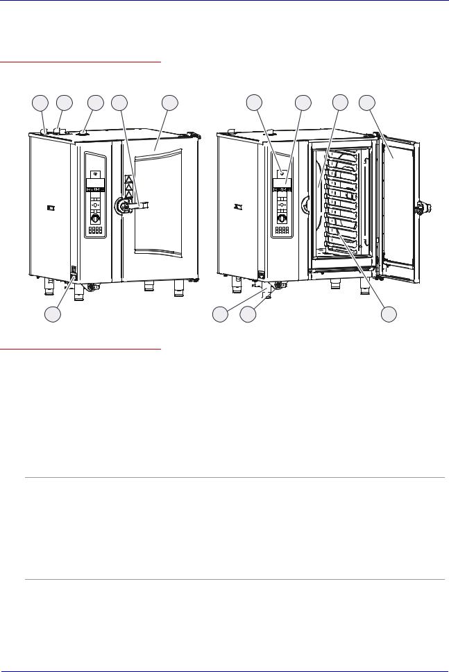
► Layout and function of the combi steamer (standard controls)
Table-top appliance construction
The following diagram shows a gas appliance and an electric appliance, representing all table-top appliances:
1 |
2 |
3 |
4 |
5 |
OGB 10.10
12
6 |
11 |
10 |
7 |
8 |
5 |
OEB 10.10
9
Components of the table-top appliances and their function
The components of the table-top appliances have the following function
No. |
Name |
Function |
|
Picture |
|
1 |
Air vent |
Controls ventilation |
|
|
|
2 |
Gas flue pipe |
On gas appliances only (vents flue gases): |
|
|
1 gas flue pipe on appliances with injection |
|
|
2 gas flue pipes on appliances with steam generator |
3 |
Low-pressure failsafe device |
Prevents the low pressure in the oven e.g. during fully automatic cleaning |
|
|
(CONVOClean system) |
4Multi-function door handle ("Hygienic Handle")
Has the following functions depending on its position:
Pointing vertically downwards: combi steamer closed, ready for cooking
Horizontal: combi steamer open, in on-latch position
20 degrees above horizontal: Combi steamer can be opened
Also has the following functions:
Additional function as far as on-latch position
In the on-latch position, door can be opened from inside oven in an emergency
Antibacterial with silver ions
5 |
Appliance door ("disappea- |
Seals the oven during cooking |
|
ring door") |
Special opening action allows it to slide back against the side of the |
|
|
combi steamer to save space |
Installation manual |
13 |
Layout and function
No. |
Name |
Function |
|
Picture |
|
6 |
|
Switches the combi steamer on and off |
|
|
|
7 |
Control panel |
Central control of the combi steamer: |
|
|
Controls: membrane keypad and tilt selector switch |
|
|
Status displays |
8 |
Oven |
Contains the food during cooking |
|
|
Has a different number of shelf levels depending on model |
9 |
Rack |
Used to hold GN containers or baking trays |
|
|
|
10 |
Hand shower |
Used for rinsing out the oven with water |
|
|
Continuous flow adjustment |
|
|
Retracts automatically into the holder after use |
|
|
|
11 |
Appliance feet |
Can be adjusted in height to allow the combi steamer to be positioned |
|
|
horizontally |
12 |
Type plate |
Used for identifying the combi steamer |
|
|
|
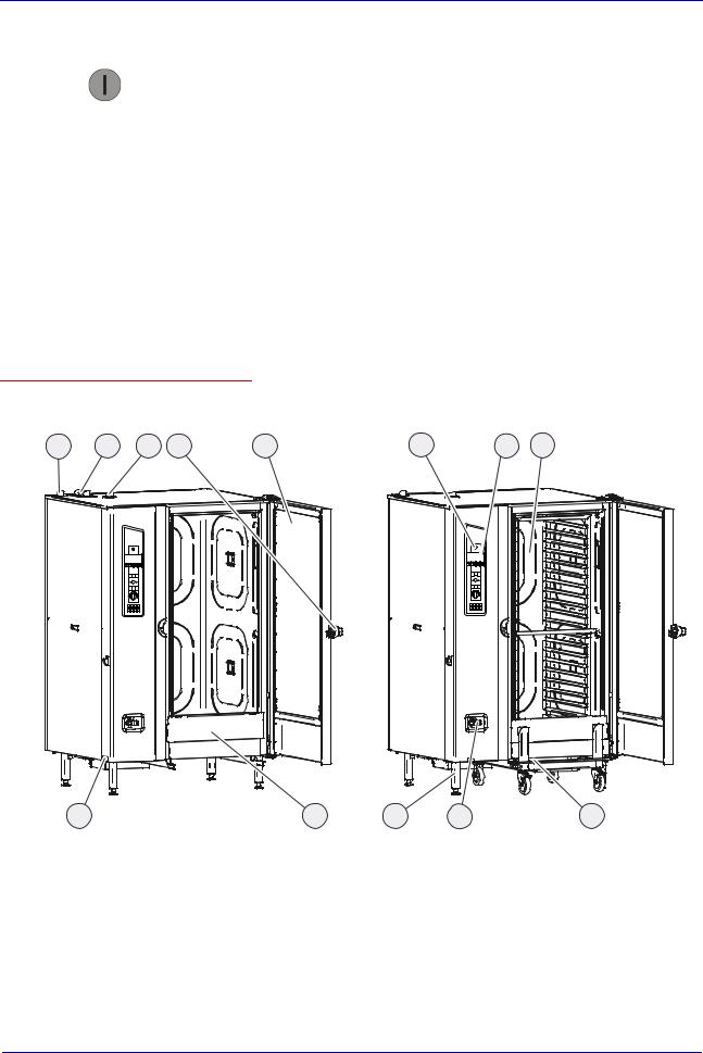
Floor-standing appliance construction
The following diagram shows a gas appliance and an electric appliance, representing all floor-standing appliances:
1 |
2 |
3 |
4 |
5 |
6 |
7 |
8 |
13 |
OGB 20.20 |
12 |
11 |
10 |
OEB 20.20 |
9 |
Installation manual |
14 |

Layout and function
Components of the floor-standing appliances and their function
The components of the table-top appliances have the following function:
No. |
Name |
Function |
|
Picture |
|
1 |
Air vent |
Controls ventilation |
|
|
|
2 |
Gas flue pipe |
On gas appliances only (vents flue gases): |
|
|
1 gas flue pipes: OGS 12.20 |
|
|
2 gas flue pipes: OGB 12.20, OGS 20.10, 20.20 |
|
|
3 gas flue pipes: OGB 20.10, 20.20 |
3 |
Low-pressure failsafe device |
Prevents the low pressure in the oven e.g. during fully automatic cleaning |
|
|
(CONVOClean system) |
4 |
Multi-function door handle |
Has the following functions depending on its position: |
|
("Hygienic Handle") |
Pointing vertically downwards: combi steamer closed |
|
|
|
|
|
Horizontal: combi steamer open, in on-latch position |
|
|
20 degrees above horizontal: Combi steamer can be opened |
|
|
Also has the following functions: |
|
|
Additional function as far as on-latch position |
|
|
In the on-latch position, door can be opened from inside oven in an |
|
|
emergency |
|
|
Antibacterial with silver ions |
|
|
|
5 |
Appliance door ("disappea- |
Seals the oven during cooking |
|
ring door") |
Special opening action allows it to slide back against the side of the |
|
|
combi steamer to save space |
6 |
|
Switches the combi steamer on and off |
|
|
|
7 |
Control panel |
Central control of the combi steamer: |
|
|
Controls: membrane keypad and tilt selector switch |
|
|
Status displays |
8 |
Oven |
Contains the food during cooking |
|
|
Has a different number of shelf levels depending on model |
9 |
Loading trolley |
Used for loading food |
|
|
|
10 |
Hand shower |
Used for rinsing out the oven with water |
|
|
Continuous flow adjustment |
|
|
Retracts automatically into the holder after use |
11 |
Appliance feet |
Can be adjusted in height to allow the combi steamer to be positioned |
|
|
horizontally |
12 |
Preheat bridge |
Used for safety purposes during preheating and cleaning |
|
|
|
13 |
Type plate |
Used for identifying the combi steamer |
|
|
|
Material
The interior and exterior structure of the combi steamer is made of stainless steel.
Installation manual |
15 |
Layout and function
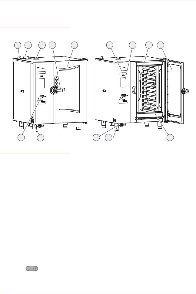
► Layout and function of the combi steamer (easyTOUCH controls)
Table-top appliance construction
The following diagram shows a gas appliance and an electric appliance, representing all table-top appliances:
1 |
2 |
3 |
4 |
5 |
6 |
7 |
8 |
5 |
 OGB 10.10
13 12
OEB 10.10
11 |
10 |
9 |
Components of the table-top appliances and their function
The components of the table-top appliances have the following function
No. |
Name |
Function |
|
picture |
|
1 |
Air vent |
Controls ventilation |
2 |
Gas flue pipe |
On gas appliances only (vents flue gases): |
|
|
1 gas flue pipe on appliances with injection |
|
|
2 gas flue pipes on appliances with steam generator |
3 |
Low-pressure failsafe |
Prevents the low pressure in the oven e.g. during fully automatic cleaning |
|
device |
(CONVOClean system) |
4 |
Multi-function door handle |
Has the following functions depending on its position: |
|
("Hygienic Handle") |
Pointing vertically downwards: combi steamer closed, ready for cooking |
|
|
Horizontal: combi steamer open, in on-latch position |
|
|
20 degrees above horizontal: Combi steamer can be opened |
|
|
Also has the following functions: |
|
|
Additional function as far as on-latch position |
|
|
In the on-latch position, door can be opened from inside oven in an |
|
|
emergency |
|
|
Antibacterial with silver ions |
|
|
|
5 |
Appliance door ("disappea- |
Seals the oven during cooking |
|
ring door") |
Special opening action allows it to slide back against the side of the combi |
|
|
steamer to save space |
|
|
|
6 |
|
Switches the combi steamer on and off |
|
|
|
Installation manual |
16 |

Layout and function
No. |
Name |
Function |
|
picture |
|
7 |
Touchscreen |
Central control of the combi steamer: |
|
|
Combi steamer operated by touching symbols on control-panel pages |
|
|
Status displays |
8 |
Oven |
Contains the food during cooking |
|
|
Has a different number of shelf levels depending on model |
|
|
|
9 |
Rack |
Used to hold GN containers or baking trays |
10 |
Hand shower |
Used for rinsing out the oven with water |
|
|
Continuous flow adjustment |
|
|
Retracts automatically into the holder after use |
11 |
Appliance feet |
Can be adjusted in height to allow the combi steamer to be positioned |
|
|
horizontally |
12 |
Type plate |
Used for identifying the combi steamer |
13 |
USB cover |
Covers the USB connector on the appliance |
Floor-standing appliance construction
The following diagram shows a gas appliance and an electric appliance, representing all floor-standing appliances:
1 |
2 |
3 |
4 |
5 |
6 |
7 |
8 |
14 |
13 |
OGB 20.20 |
12 |
11 |
10 |
OEB 20.20 |
9 |
Installation manual |
17 |

Layout and function
Components of the floor-standing appliances and their function
The components of the table-top appliances have the following function:
No. |
Name |
Function |
|
picture |
|
|
|
|
1 |
Air vent |
Controls ventilation |
2 |
Number of gas flue pipes |
On gas appliances only (vents flue gases): |
|
|
1 gas flue pipes: OGS 12.20 |
2 gas flue pipes: OGB 12.20, OGS 20.10, 20.203 gas flue pipes: OGB 20.10, 20.20
3Low-pressure failsafe device
4Multipurpose door handle ("Hygienic Handle")
Prevents the low pressure in the oven e.g. during fully automatic cleaning (CONVOClean system)
Has the following functions depending on its position:
Pointing vertically downwards: combi steamer closed
Horizontal: combi steamer open but in on-latch position
20 degrees above horizontal: Combi steamer can be opened
Also has the following functions:
Additional function as far as on-latch position
In the on-latch position, door can be opened from inside oven in an emergency
Antibacterial with silver ions
5 |
Appliance door ("disappea- |
Seals the oven during cooking |
|
|
ring door") |
Special opening action allows it to slide back against the side of the combi |
|
|
|
|
steamer to save space |
6 |
|
Switches the combi steamer on and off |
|
|
|
|
|
7 |
Touchscreen |
Central control of the combi steamer: |
|
|
|
Combi steamer operated by touching symbols on control-panel pages |
|
|
|
Status displays |
|
8 |
Oven |
Contains the food during cooking |
|
|
|
Has a different number of shelf levels depending on model |
|
9 |
Loading trolley |
Used for loading food |
|
10 |
Hand shower |
Used for rinsing out the oven with water |
|
|
|
Continuous flow adjustment |
|
|
|
Retracts automatically into the holder after use |
|
11 |
Appliance feet |
Can be adjusted in height to allow the combi steamer to be positioned |
|
|
|
horizontally |
|
12 |
Preheat bridge |
Used for safety purposes during preheating and cleaning |
|
|
|
|
|
13 |
Type plate |
Used for identifying the combi steamer |
|
|
|
|
|
14 |
USB cover |
Covers the USB connector on the appliance |
|
Material
The interior and exterior structure of the combi steamer is made of stainless steel.
Installation manual |
18 |

For your safety
3 For your safety
Purpose of this chapter
This chapter provides you with all the information you need in order to use the combi steamer safely without putting yourself or others at risk.
This is a particularly important chapter that you should read through carefully.
Contents |
|
|
This chapter contains the following topics: |
|
|
|
|
Page |
Basic safety code |
20 |
|
Hazards and safety precautions |
21 |
|
Requirements for safe setup, installation and preparation for first-time use23 |
||
Requirements to be met by personnel, personal protection equipment and |
||
working positions |
24 |
|
Warning signs on the combi steamer |
25 |
|
Safety devices |
27 |
|
Installation manual |
19 |
For your safety
► Basic safety code
Object of this safety code
This safety code aims to ensure that all persons who use the combi steamer have a thorough knowledge of the hazards and safety precautions, and that they follow the safety instructions given in the user manual and on the combi steamer. If you do not follow this safety code, you risk potentially fatal injury and property damage.
Referring to the user manuals included in the customer documentation
Follow the instructions below:
Read in full the chapter "For Your Safety" and the chapters that relate to your work.
Always keep to hand the user manuals included in the customer documentation for reference.
Pass on the user manuals included in the customer documentation with the combi steamer if it changes ownership.
Working with the combi steamer
Follow the instructions below:
Only those persons who satisfy the requirements stipulated in this user manual are permitted to use the combi steamer.
People (including children) who, because of their physical, sensory or intellectual capabilities, or because of their lack of experience or knowledge, are incapable of using the appliance safely, must not use this equipment without the supervision or guidance of a responsible person.
Only use the combi steamer for the specified use. Never, under any circumstances, use the combi steamer for other purposes that may suggest themselves.
Take all the safety precautions specified in this user manual and on the combi steamer. In particular, use the prescribed personal protection equipment.
Only stand in the working positions specified.
Do not make any changes to the combi steamer, e.g. removing parts or fitting un-approved parts. In particular, you must not disable any safety devices.
Related topics |
|
Intended use of your combi steamer.................................................................................................. |
12 |
Warning signs on the combi steamer................................................................................................. |
25 |
Hazards and safety precautions......................................................................................................... |
21 |
Safety devices.................................................................................................................................... |
27 |
Requirements to be met by personnel, personal protection equipment and working positions ........ |
24 |
Installation manual |
20 |

For your safety
► Hazards and safety precautions
Meaning
This section describes the potential hazards that authorized personnel may be exposed to when moving and installing the appliance, when preparing the appliance for use and when taking it out of service. It stipulates the measures required to minimize these hazards as far as possible.
Moving the appliance and taking it out of service
When moving the combi steamer and taking it out of service, be aware of the following hazards and take the specified preventive actions:
Hazard |
Where or in what situations |
Preventive action |
Safety device |
|
does the hazard arise? |
|
|
|
|
|
|
Risk of crushing from |
When lifting up and setting down |
heavy items being carried |
the items being carried |
Only allow suitably trained |
None |
personnel to move the appli- |
|
ance using a pallet truck or |
|
forklift truck |
|
Overstressing your body |
When setting up and moving the |
Do not exceed safety limits for None |
|
appliance |
lifting and carrying |
|
|
Use lifting gear |
Hazard posed by damaged |
When moving and dismantling |
Disconnect all gas, water and None |
gas, water and electrical |
connected appliances |
electrical connections before |
connections |
|
moving the appliance and |
|
|
before taking it out of service. |
|
|
Work must only be performed |
|
|
by qualified electricians from |
|
|
an approved customer service |
|
|
office and by approved gas |
|
|
fitters. |
Installation manual |
21 |

For your safety
Installation and preparing for first-time use
When installing the combi steamer and preparing it for first-time use, be aware of the following hazards and take the specified preventive actions:
|
Hazard |
Where or in what situations |
Preventive action |
Safety device |
|
|
does the hazard arise? |
|
|
|
Risk from live parts |
Under the cover |
Work on the electrical system |
Cover |
|
|
Under the control panel |
must only be performed by |
|
|
|
|
qualified electricians from an |
|
|
|
|
approved customer service |
|
|
|
|
office |
|
|
|
|
Professional working |
|
|
|
|
Disconnect power supply |
|
|
|
|
before removing the cover |
|
|
Risk of electric shock if the |
On the combi steamer |
Use a permanent connection. None |
|
|
water supply is leaking or |
In the entire working area |
Use only suitable pipes that |
|
|
cracked. |
|
comply with DIN EN 61770. |
|
|
|
|
|
|
|
Risk of explosion from gas |
Where combi steamer is installed |
Work on the gas system must |
None |
|
|
|
only be performed by an |
|
|
|
|
approved gas fitter |
|
|
|
|
Professional working |
|
|
|
|
On smelling gas: |
|
|
|
|
Disconnect gas supply at the |
|
|
|
|
shut-off device |
|
|
|
|
Ventilate room |
|
|
|
|
Do not operate any electrical |
|
|
|
|
equipment |
|
|
|
|
Do not create naked flames |
|
|
|
|
Get help |
|
|
Risk of suffocation from |
Where combi steamer is installed |
Work on the gas system must |
None |
|
faulty combustion |
|
only be performed by an |
|
|
|
|
approved gas fitter |
|
|
Risk of suffocation from |
Where combi steamer is installed |
Work on the gas system must |
None |
|
insufficient supply of air for |
|
only be performed by an |
|
|
combustion |
|
approved gas fitter |
|
|
|
|
|
|
Installation manual |
22 |

For your safety
►Requirements for safe setup, installation and preparation for firsttime use
Meaning
Safe operation of the combi steamer is only guaranteed if it has first been set up, installed, connected and prepared for use in accordance with the basic requirements specified here.
Stability
Observe the following requirements to ensure that the combi steamer is installed in a stable situation:
The standing surface must be flat and sufficiently strong to bear the weight of the appliance. This must include the maximum permissible loading weight for the appliance model concerned.
The height-adjustable feet on the combi steamer must be adjusted to ensure the appliance is positioned horizontally on the standing surface.
On vehicles and on-board ships, the combi steamer must be suitably anchored to secure it from tipping over or sliding about.
Installing the connection to the electrical supply
Observe the following requirements to prevent hazards caused by faulty electrical connections:
Only qualified electricians from an approved customer service office are permitted to perform work on electrical equipment.
The connection to the electrical supply must be installed in accordance with applicable local regulations of the professional associations and power supply company.
The case of the appliance must be grounded in a suitable manner and connected to an equipotential bonding system.
All electrical connections must be checked when the appliance is prepared for first-time use to ensure cables are laid correctly and connections are made properly.
Installing the gas supply
Observe the following requirements to prevent hazards caused by faulty connections to gas appliances:
Only approved gas fitters are permitted to connect the combi steamer to the gas supply.
The connection to the gas supply must be installed in accordance with applicable local regulations of the professional associations and gas supply company.
All gas supply installations must be checked carefully when the appliance is prepared for first-time use to ensure the connections are gas-tight and installed correctly.
Environmental conditions at the installation location
To ensure safe operation of the appliance, the environmental conditions at the intended installation location must meet the following requirements:
It is prohibited to store flammable gases or liquids in an area exposed to heat radiated from the appliance.
It is prohibited to operate deep-fat fryers or appliances that use hot, uncovered fat, in an area that can be reached by the water jet from the hand shower.
For the operation of gas appliances, there must be a guaranteed, unrestricted supply of fresh air, and the ventilation system must be installed in accordance with regulations.
Installation manual |
23 |

For your safety
►Requirements to be met by personnel, personal protection equipment and working positions
Requirements to be met by personnel
Those people using the combi steamer must meet the following requirements:
Personnel |
Tasks |
Qualifications |
Personal protection equipment |
|
|
|
required |
|
|
|
|
Equipment mover |
Conveying within the |
Trained in the use of a |
|
establishment |
pallet truck and forklift |
|
|
truck |
Safety boots
Hard hat (e.g. when heavy loads are being lifted, working overhead...)
Service engineer Setting up the appliance
Connecting the appliance
Preparing the appliance for first-time use
Taking the appliance out of service
Instructing the user
Is an employee of an approved customer service unit.
Has relevant technical training.
Is trained in the particular appliance.
Work wear and personal protection equipment depending on the job that needs doing as specified in national regulations.
Gas fitter |
Connecting the appliance: |
|
gas |
|
Isolating the appliance |
|
from the gas supply mains |
Is a gas fitter authorized by the gas supply company.
Has relevant professional training.
Work wear and personal protection equipment depending on the job that needs doing as specified in national regulations.
Electrical fitter |
Connecting the appliance: |
|
electric |
|
Isolating the appliance |
|
from the electrical supply |
|
mains |
Is an employee of an approved customer service unit.
Has relevant professional training.
Is a qualified electrician.
Work wear and personal protection equipment depending on the job that needs doing as specified in national regulations.
Working positions when installing and preparing the appliance for first-time use
The working position for personnel installing and preparing the appliance for first-time use is the entire appliance area.
Installation manual |
24 |
For your safety
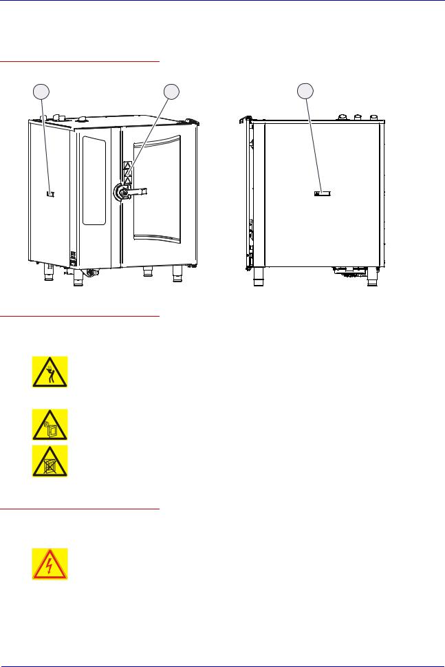
► Warning signs on the combi steamer
Where are the warning signs fitted?
The warning signs are located in the following positions on the combi steamer:
1 |
2 |
OGB 10.10
1 |
OGB 10.10
Warnings on the appliance door
The following warning signs are fitted on the appliance door above the door handle (2):
Warning sign |
Description |
|
Warning of hot liquids |
|
Spillage of hot liquid foods can result in scalds if the upper shelves are loaded with liquids |
|
or foods that produce liquid during cooking. Shelves above the level marked by this |
|
warning sign (1.60 m) may not be seen by all users and should not, therefore, be used for |
|
liquids or foods that produce liquid during cooking. |
|
Warning of hot steam and vapor |
|
There is a risk of scalding from hot steam and vapor escaping when the appliance door is |
|
opened. |
|
|
|
Warning of corrosive cleaning agents injected into oven |
|
If the appliance door is opened during fully automatic cleaning (CONVOClean system), |
|
there is a risk of chemical skin burns from contact with cleaning agents being injected |
|
during the cleaning program. |
Warning signs on the side cover of the combi steamer
The following warning signs are fitted on the side cover (1) of the combi steamer:
Warning sign |
Description |
|
Warning of electric shock |
|
There is a risk of electric shock from live parts if the appliance cover is opened. |
|
|
Installation manual |
25 |

For your safety
Warning signs on the loading trolley for floor-standing appliances
The following warning signs are fitted on the loading trolley of floor-standing appliances:
|
Warning sign |
Description |
|
|
Warning of hot liquids |
|
|
Spillage of hot liquid foods can result in scalds if the upper shelves are loaded with liquids |
|
|
or foods that produce liquid during cooking. Shelves above the level marked by this |
|
|
warning sign (1.60 m) may not be seen by all users and should not, therefore, be used for |
|
|
liquids or foods that produce liquid during cooking. |
|
|
|
Installation manual |
26 |
For your safety
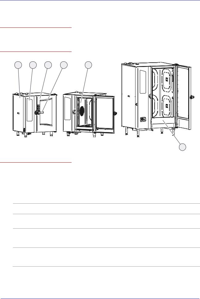
► Safety devices
Meaning
The combi steamer has a number of safety devices to protect the user from hazards. It is absolutely essential that all safety devices are fitted and in working order when operating the combi steamer
Position
The following diagrams show the location of the safety devices:
16 |
26 |
3 |
4 |
5 |
OGB 10.10 |
OEB 10.10 |
OGB 20.20 |
|
|
10 |
Functions
The following table enumerates all the safety devices on the combi steamer, explains their function and describes the check procedure:
No. |
Safety device |
Function |
Check |
1 |
Cover can only be |
Prevents live parts from being |
Check that the cover is in place |
|
removed using tool |
touched accidentally |
|
Prevents access to the moving fan from the wiring compartment
2 |
Control panel can only |
Prevents live parts from being |
Ensure that the control panel is in |
|
be removed using a tool |
touched accidentally |
place |
3 |
Appliance door: |
Protects the operator and outside |
|
|
environment from hot steam |
Check regularly for scratches, cracks, indentations etc. and replace door if any are found
4 |
On-latch position of |
Prevents scalding of user's face |
|
appliance door |
and hands from escaping steam |
Check door positions at low temperature as described in
Opening the appliance door safely in the user manual.
5Suction panel in oven; can only be removed using tool
Prevents access to the moving fan and ensures good heat distribution.
See
Removing and fitting the suction panel in the user manual for further details.
Installation manual |
27 |

For your safety
No. |
Safety device |
Function |
Check |
|
6 |
Magnetic door switch: |
Switches off the fan and heater |
Check magnetic door switch at low |
|
(no picture) |
electrical door sensor in |
when the appliance door is opened |
temperature: |
|
appliance door |
|
Action |
||
|
|
|||
|
|
|
Open the appliance door fully |
|
|
|
|
Press Start |
|
|
|
|
Result |
|
|
|
|
Motor must not start up |
|
7 |
Emergency opening in |
Appliance door in the on-latch |
Check at low temperature: |
|
(no picture) |
appliance door; |
position: |
put the appliance door in the on- |
|
|
Prevents anyone being |
Allows the appliance door to be |
latch position (see Opening the |
|
|
appliance door safely in the user |
|||
|
locked inside the oven |
pushed open from the inside after |
||
|
manual) |
|||
|
accidentally |
shutting the door. |
||
|
Action |
|||
|
|
|
||
|
|
|
From the outside, pull forcefully on |
|
|
|
|
the top left of the appliance door |
|
|
|
|
Result |
|
|
|
|
The appliance door must open. |
|
8 |
Automatic rinsing after |
Re-starts fully automatic cleaning |
This test is a software function. |
|
(no picture) |
power failure in case |
(CONVOClean system) in a de- |
There is no need for the operator |
|
cleaning agent left in |
fined state after power failure |
to perform a test. |
||
|
||||
|
combi steamer |
|
|
9 |
Spray-guard |
(no picture) |
|
Stops the cleaning agent being injected during fully automatic cleaning (CONVOClean system) when the appliance door is opened Prompt to close the appliance door
The operability of the magnetic door switch is checked by the software at the beginning of each cleaning program
10 |
Preheat bridge |
Prevents scalding from escaping |
|
|
steam when the loading trolley is |
|
|
not in the floor-standing appliance |
|
|
during preheating |
See
Inserting and removing the preheat bridge (floor-standing appliances only) in the user manual for further details
11 (installed Disconnection device |
Installed by the customer close to |
by customer) |
the appliance; easily visible and |
|
accessible, 3-pole action, minimum |
|
contact separation 3 mm. |
|
Used to disconnect the appliance |
|
from the power supply during |
|
cleaning, repair and maintenance |
|
work and in case of danger. |
Action
Trip the disconnection device.
Check at the X10 terminal strip on the appliance that there is no voltage at all three poles.
12 (installed Gas shut-off device |
Installed by customer close to |
by customer) |
appliance in easily accessible |
|
position and clearly labeled. |
|
Used to disconnect the appliance |
|
from the gas supply during clean- |
|
ing, repair and maintenance work |
|
and in case of danger. |
Action
Close gas shut-off device.
Check that the appliance is isolated from the gas supply.
Installation manual |
28 |

Moving and setting up the appliance
4 Moving and setting up the appliance
Purpose of this chapter
This chapter specifies all the requirements for the installation location of the combi steamer, and explains the correct on-site procedure for conveying and unpacking the combi steamer, lifting it off the pallet and setting it up.
Contents
This chapter contains the following topics: |
|
|
Page |
Requirements for the installation location |
30 |
Taking to the installation location |
35 |
Unpacking |
36 |
Setting up table-top appliances |
39 |
Setting up floor-standing appliances |
42 |
Installation manual |
29 |
 Loading...