

Page 1

FM-3
Programming Module
Reference Manual
P/N 400508-01
Revision: A8
Date: March 10, 2004
© Control Techniques Drives, I nc. 2000-2004
Page 2

Page 3

FM-3
Programming Module
Reference Manual
Information furnished by Control Techniques Drives Inc. (Control Techniques) is believed to be
accurate and reliable. However, no responsibility is assumed by Control Techniques for its use.
Control Techniques reserves the right to change the design or operation of the equipment described
herein and any associated motion products without notice. Control Techniques also assumes no
responsibility for any errors that may appear in this document. Information in this document is subject
to change without notice.
P/N 400508-01
Revision: A8
Date: March 10, 2004
© Control Techniques Drives, Inc. 2000-2004
Page 4

© Control Techniques Drives, Inc. 2000-2004
Part Number: 400508-01
Revision: A8
Date: March 2004
Printed in United States of America
Information in this document is subject to change without notice. No part of this document may be
reproduced or transmitted in any form or by any means, electronic or mechanical, for any purpose,
without the express written permission of Control Techniques.
The following are trademarks of Control Techniques and may not be reproduced in any fashion
without written approval of Control Techniques: EMERSO N M otion Control,
EMERSON Motion Control PowerTools, AXIMA, “Motion Made Easy.”
Control Techniques is a division of EMERSON Co.
Control Techniques, Inc. is not affiliated with Microsoft Corporation, owner of the Microsoft,
Windows, and Windows NT tradema rks.
This document has been prepared to conform to the current released version of the product. Because
of our extensive development efforts and our desire to further improve and enhance the product,
inconsistencies may exist between the product and documentation in some instances. Call your
customer support representative if you encounter an inconsistency.
ii
Page 5

Customer Support
Control Techniques
12005 Technology Drive
Eden Prairie, Minnesota 55344-3620
U.S.A.
Telephone: (952) 995-8000 or (800) 893-2321
It is Control Tech niques’ goal t o ensure yo ur greatest possible satis faction with the operation
of our products. We are dedicated to providing fast, friendly, and accurate assistance. That is
why we offer you so many ways to get the support you need. Whether it’s by phone, fax or
modem, you can access Control Techniques support information 24 ho urs a day, seven days
a week. Our wide range of services include:
FAX (952) 995-8099
You can FAX questions and comments to Control Techniques. Just send a FAX to the number
listed above.
Website and Email www.emersonct .com
Website: www.emersonct.com
Email: info@emersonct.com
If you have Internet capabilities, you also have access to technical support using our website.
The website includes technical notes, frequently asked questions, release notes and other
technical documentation. This di rect technical suppo rt connection lets you request assistance
and exchange software files electronically.
Technical Support (952) 995-8033 or (800) 893-2321
Email: service@emersonct.com
Control Techniques’ “Motion Made Easy” products are backed by a team of professionals
who will service your installation. Our technical support center in Eden Prairie, Minnesota is
ready to help you solve those occasional prob lems over the telephone. Our techni cal support
center is available 24 hours a day for emergency service to help speed any problem solving.
Also, all hardware replacement parts, if needed, are available through our customer service
organization.
When you call, please be at your computer, with y our documen tation easily available, and b e
prepared to provide the following information:
• Product version number, found by choosing About from the Help menu
• The type of controller or product you are using
iii
Page 6

• Exact wording of any messages that appear on your screen
• What you were doing when the problem occurred
• How you tried to solve the problem
Need on-site help? Control Techniques provides service, in most cases, the next day. Just call
Control Techniques’ technical support center when on-site service or maintenance is
required.
Training Services (952) 995-8000 or (800) 893-2321
Email: training@emersonct.com
Control Techniques maintains a highly trained s taf f of ins tructo r s to familiarize customers
with Control Techniqu es’ “Motion Made Easy” prod ucts and their applicatio ns. A number of
courses are offered, many of which can be taught in your plant upon request.
Application Engineering (952) 995-8000 or (800) 893-2321
Email: applengr@emersonct.com
An experienced staff of factory application engi neers provides complete customer support for
tough or complex applications. Our engineers offer you a broad base of experience and
knowledge of electronic motion control applications.
Customer Service (Sales) (952) 995-8000 or (800) 893-2321
Email: customer.service@emersonct.com
Authorized Control Techniques distributors may place orders directly with our Customer
Service department. Contact the Customer Service department at this number for the
distributor nearest you.
Document Conventions
Manual conventions have been established to help you learn to use this manual quickly and
easily. As much as possible, these conventions correspond to those found in other Microsoft®
Windows® compatible software documentation.
Menu names and options are printed in bold type: the File menu.
Dialog box names begin with uppercase letters: the Axis Limits dialog box.
Dialog box field names are in quotes: “Field Name.”
Button names are in italic: OK button.
Source code is printed in Courier font: Case ERMS.
iv
Page 7

In addition, you will find the following typographic conventions throughout this manual.
EN
This Represents
bold
italic
ALL CAPITALS Directory names, file names, key names, and acronyms.
SMALL CAPS Non-printable ASCII control characters.
KEY1+KEY2
example: (Alt+F)
KEY1,KEY2
example: (Alt,F)
Characters that you must type exactly as they appear. For example, if you are directed to type
a:setup, you should type all the bold characters exactly as they are printed.
Placeholders for information you must provide. For example, if you are directed to type
filename, you should type the actual name for a file instead of the word shown in italic type.
A plus sign (+) between key names means to press and hold down the first key while you press
the second key.
A comma (,) between key names means to press and release the keys one after the other.
Note
For the purpose of this manual and p roduct , “Note” indicates essential inform ation about
the product or the respective part of the manual.
EN Only
For the purpose of thi s manual and product , the “EN” symbol indicates information about
the EN drive specifically.
Throughout this manual, the word “drive” refers to an EN or MDS drive.
“Warning” indicates a potentially hazard ous situation that, if not av oided, co uld result in
death or serious injury.
“Caution” indicates a potentially hazardous situation that, if not avoided, may result in
minor or moderate injury.
“Caution” used without the safety alert symbol indicates a potentially hazardous situation
that, if not avoided, may result in property damage.
v
Page 8

Safety Instructions
General Warning
Failure to follow safe installation guidelines can cause death or serious injury. The voltages
used in the product can cause se vere electric shock and/or burns and could be lethal . Extreme
care is necessary at all times when working with or adjacent to the product. The installation
must comply with all relevant safety legislation in the country of use.
Qualified Per s on
For the purpose of this manual and product, a “qualified person” is one who is familiar with
the installation, construction and operation of the equipment and the hazards involved. In
addition, this individual has the following qualif ications:
• Is trained and authorized to energize, de-energize, clear and ground and tag circuits and
equipment in accordance with established safety practices.
• Is trained in the proper care and use of protective equipment in accordance with
established safety practices.
• Is trained in rendering first aid.
Reference Materials
The following related reference and installation manuals may be useful with your particular
system.
• Function Module Installation Manual (P/N 400506-03)
• Epsilon Eb and EN Drives Reference Manual (P/N 400501-01)
• PowerTools Software User’s Guid e (P/N 400503-01)
• FM-3 and FM-4 Connectivity Modules Reference Manual (P/N 400508-04)
• Modular Drive System (MDS) Reference Manual (P/N 400525-01)
vi
Page 9

Safety Precautions
This product is intended for professional integration into a complete system. If you install the
product incorrectly, it may present a safety hazard. The product and system may use high
voltages and currents, carry a high level of stored electrical energy, or control mechanical
equipment that can cause injury.
You should give close attention to the electrical installation and system design to avoid
hazards either in normal op eration or in the event of eq uipmen t malf unction . Sy stem des ign,
installation, commiss ionin g and mainten ance mu st be carri ed out b y perso nnel who hav e the
necessary training and experience. Read and follow this safety information an d the instruction
manual carefully.
Enclosure
This product is intended to be mounted in an enclosure which prevents access except by
trained and authorized personnel, and which prevents the ingress of contamination. This
product is designed for use in an environment classified as pollution degree 2 in accordance
with IEC664-1. This means that only dry, non-conducting contamination is acceptable.
Safety Considerations
Setup, Commissioning and M aintenance
It is essential that you give careful consideration to changes to drive settings. Depending on
the application, a change could have an impact on safety. You must take appropriate
precautions against inadvertent changes or tampering. Restoring default parameters in certain
applications may cause unpredictable or hazardous operation.
Safety of Machinery
Within the European Union all machinery with which this product is used must comply with
Directive 89/392/EEC, Safety of Machinery.
The product has been designed and tested to a high standard, and failures are very unlikely.
However the level of integrity offered by the product’s control function – for example stop/
start, forward/reverse and maximum speed – is not sufficient for use in safety-critical
applications without additional independent channels of protection. All applications where
malfunction coul d cause injury or loss of lif e must be s ubject to a risk assessment, an d further
protection provided where needed.
General warning
Failure to follow safe installation guidelines can cause dea th or seriou s injury. The voltage s used in
this unit can cause severe electric shock and/or burns, and could be lethal. Extreme care is necessary
at all times when work ing with or a djacent to th is equipment. T he installatio n must comply with all
vii
Page 10

relevant safety legislation in the country of use.
AC supply isolati on device
The AC supply must be removed from the drive using an approved isolation device or disconnect
before any servicing work is performed, other than adjustments to the settings or parameters
specified in the manual. The driv e contain s capacitors whi ch remain charged to a poten tially lethal
voltage after the supply has been removed. Allow at least 3 mi nutes after removing the suppl y
before carrying out any work whic h may involve contact with electrical connections to the drive.
Products connected by plug and socket
A special hazard may exist where the drive is incorporated into a product which is connected to the
AC supply by a plug and socket. When unplugged, the pi ns of the plug may be connected to the
drive input, which is only separated from the charge stored in the bus capacitor by semiconductor
devices. To avoid any possibility of electric shock from the pins, if they are accessible, a means
must be provided for automatically disconnecting the plug from the drive (that is, a latching
contactor).
Grounding (Earthing, equipotential bonding)
The drive must be grounded by a conductor sufficient to carry all possible fault current in the event
of a fault. The ground connections shown in the manual must be followed.
Fuses
Fuses or over-current protection must be provided at the input in accordance with the instructions
in the manual.
Isolation of control circuits
The installer must ensure that t he external control circuits are isolated from human contact by at
least one layer of insulation rated for use at the applied AC supply voltage.
viii
Page 11

Table of Contents
Introduction 1
Operational Overview 3
Software Interface . . . . . . . . . . . . . . . . . . . . . . . . . . . . . . . . . . . . . . . . . . . . . . . . . . . . . . . . . . . . . 3
PowerTools Pro Setup Software . . . . . . . . . . . . . . . . . . . . . . . . . . . . . . . . . . . . . . . . . . . . . . . . . . 3
Keypad Interface . . . . . . . . . . . . . . . . . . . . . . . . . . . . . . . . . . . . . . . . . . . . . . . . . . . . . . . . . . . . . . 4
How Motion Works. . . . . . . . . . . . . . . . . . . . . . . . . . . . . . . . . . . . . . . . . . . . . . . . . . . . . . . . . . . . 7
How Jogging Works . . . . . . . . . . . . . . . . . . . . . . . . . . . . . . . . . . . . . . . . . . . . . . . . . . . . . . . . . . . 7
How Home Works. . . . . . . . . . . . . . . . . . . . . . . . . . . . . . . . . . . . . . . . . . . . . . . . . . . . . . . . . . . . . 8
How Indexes Work . . . . . . . . . . . . . . . . . . . . . . . . . . . . . . . . . . . . . . . . . . . . . . . . . . . . . . . . . . . 18
How Communications Work. . . . . . . . . . . . . . . . . . . . . . . . . . . . . . . . . . . . . . . . . . . . . . . . . . . . 23
Brake Operation. . . . . . . . . . . . . . . . . . . . . . . . . . . . . . . . . . . . . . . . . . . . . . . . . . . . . . . . . . . . . . 29
Setting Up Parameters 31
Setup View. . . . . . . . . . . . . . . . . . . . . . . . . . . . . . . . . . . . . . . . . . . . . . . . . . . . . . . . . . . . . . . . . . 31
Status Online Tab (Online Only). . . . . . . . . . . . . . . . . . . . . . . . . . . . . . . . . . . . . . . . . . . . . . . . . 34
Information Tab (Online Only). . . . . . . . . . . . . . . . . . . . . . . . . . . . . . . . . . . . . . . . . . . . . . . . . . 37
User Units View . . . . . . . . . . . . . . . . . . . . . . . . . . . . . . . . . . . . . . . . . . . . . . . . . . . . . . . . . . . . . 38
Master Units View. . . . . . . . . . . . . . . . . . . . . . . . . . . . . . . . . . . . . . . . . . . . . . . . . . . . . . . . . . . . 42
Position View. . . . . . . . . . . . . . . . . . . . . . . . . . . . . . . . . . . . . . . . . . . . . . . . . . . . . . . . . . . . . . . . 46
Velocity View . . . . . . . . . . . . . . . . . . . . . . . . . . . . . . . . . . . . . . . . . . . . . . . . . . . . . . . . . . . . . . . 50
Ramps View. . . . . . . . . . . . . . . . . . . . . . . . . . . . . . . . . . . . . . . . . . . . . . . . . . . . . . . . . . . . . . . . . 52
Torque View . . . . . . . . . . . . . . . . . . . . . . . . . . . . . . . . . . . . . . . . . . . . . . . . . . . . . . . . . . . . . . . . 54
Tuning View . . . . . . . . . . . . . . . . . . . . . . . . . . . . . . . . . . . . . . . . . . . . . . . . . . . . . . . . . . . . . . . . 56
Faults View . . . . . . . . . . . . . . . . . . . . . . . . . . . . . . . . . . . . . . . . . . . . . . . . . . . . . . . . . . . . . . . . . 59
PLS View. . . . . . . . . . . . . . . . . . . . . . . . . . . . . . . . . . . . . . . . . . . . . . . . . . . . . . . . . . . . . . . . . . . 61
Setup NVM View . . . . . . . . . . . . . . . . . . . . . . . . . . . . . . . . . . . . . . . . . . . . . . . . . . . . . . . . . . . . 64
User Variables View . . . . . . . . . . . . . . . . . . . . . . . . . . . . . . . . . . . . . . . . . . . . . . . . . . . . . . . . . . 65
User Bits View. . . . . . . . . . . . . . . . . . . . . . . . . . . . . . . . . . . . . . . . . . . . . . . . . . . . . . . . . . . . . . . 67
I/O Setup Group. . . . . . . . . . . . . . . . . . . . . . . . . . . . . . . . . . . . . . . . . . . . . . . . . . . . . . . . . . . . . . 72
Assignments. . . . . . . . . . . . . . . . . . . . . . . . . . . . . . . . . . . . . . . . . . . . . . . . . . . . . . . . . . . . . . . . . 72
Assignments View. . . . . . . . . . . . . . . . . . . . . . . . . . . . . . . . . . . . . . . . . . . . . . . . . . . . . . . . . . . . 72
Selector View. . . . . . . . . . . . . . . . . . . . . . . . . . . . . . . . . . . . . . . . . . . . . . . . . . . . . . . . . . . . . . . . 77
Input Lines View. . . . . . . . . . . . . . . . . . . . . . . . . . . . . . . . . . . . . . . . . . . . . . . . . . . . . . . . . . . . . 81
Output Lines View. . . . . . . . . . . . . . . . . . . . . . . . . . . . . . . . . . . . . . . . . . . . . . . . . . . . . . . . . . . . 82
Analog Inputs View. . . . . . . . . . . . . . . . . . . . . . . . . . . . . . . . . . . . . . . . . . . . . . . . . . . . . . . . . . . 83
Motion Group . . . . . . . . . . . . . . . . . . . . . . . . . . . . . . . . . . . . . . . . . . . . . . . . . . . . . . . . . . . . . . . 85
ix
Page 12

Jog View . . . . . . . . . . . . . . . . . . . . . . . . . . . . . . . . . . . . . . . . . . . . . . . . . . . . . . . . . . . . . . . . . . . 86
Home View . . . . . . . . . . . . . . . . . . . . . . . . . . . . . . . . . . . . . . . . . . . . . . . . . . . . . . . . . . . . . . . . . 91
Index View . . . . . . . . . . . . . . . . . . . . . . . . . . . . . . . . . . . . . . . . . . . . . . . . . . . . . . . . . . . . . . . . . 96
Gearing View . . . . . . . . . . . . . . . . . . . . . . . . . . . . . . . . . . . . . . . . . . . . . . . . . . . . . . . . . . . . . . 107
Stopping Motion . . . . . . . . . . . . . . . . . . . . . . . . . . . . . . . . . . . . . . . . . . . . . . . . . . . . . . . . . . . . 110
Network Group . . . . . . . . . . . . . . . . . . . . . . . . . . . . . . . . . . . . . . . . . . . . . . . . . . . . . . . . . . . . . 111
Modbus View . . . . . . . . . . . . . . . . . . . . . . . . . . . . . . . . . . . . . . . . . . . . . . . . . . . . . . . . . . . . . . 111
DeviceNet View . . . . . . . . . . . . . . . . . . . . . . . . . . . . . . . . . . . . . . . . . . . . . . . . . . . . . . . . . . . . 113
Profibus View . . . . . . . . . . . . . . . . . . . . . . . . . . . . . . . . . . . . . . . . . . . . . . . . . . . . . . . . . . . . . . 113
Ethernet View . . . . . . . . . . . . . . . . . . . . . . . . . . . . . . . . . . . . . . . . . . . . . . . . . . . . . . . . . . . . . . 113
Programming 115
Program Toolbar Icons . . . . . . . . . . . . . . . . . . . . . . . . . . . . . . . . . . . . . . . . . . . . . . . . . . . . . . . 116
Programs . . . . . . . . . . . . . . . . . . . . . . . . . . . . . . . . . . . . . . . . . . . . . . . . . . . . . . . . . . . . . . . . . . 119
Program Instruction Types . . . . . . . . . . . . . . . . . . . . . . . . . . . . . . . . . . . . . . . . . . . . . . . . . . . . 119
Adding and Deleting Programs. . . . . . . . . . . . . . . . . . . . . . . . . . . . . . . . . . . . . . . . . . . . . . . . . 131
Run Anytime Programs. . . . . . . . . . . . . . . . . . . . . . . . . . . . . . . . . . . . . . . . . . . . . . . . . . . . . . . 132
Example Programs . . . . . . . . . . . . . . . . . . . . . . . . . . . . . . . . . . . . . . . . . . . . . . . . . . . . . . . . . . 134
Parameter Descriptions 143
Installation 183
Basic Installation Notes. . . . . . . . . . . . . . . . . . . . . . . . . . . . . . . . . . . . . . . . . . . . . . . . . . . . . . . 183
Mechanical Installation. . . . . . . . . . . . . . . . . . . . . . . . . . . . . . . . . . . . . . . . . . . . . . . . . . . . . . . 183
Software Installation . . . . . . . . . . . . . . . . . . . . . . . . . . . . . . . . . . . . . . . . . . . . . . . . . . . . . . . . . 185
Starting and Exiting PowerTools . . . . . . . . . . . . . . . . . . . . . . . . . . . . . . . . . . . . . . . . . . . . . . . 186
Accessing Help . . . . . . . . . . . . . . . . . . . . . . . . . . . . . . . . . . . . . . . . . . . . . . . . . . . . . . . . . . . . . 187
Quick Start 189
Basic Setup Steps . . . . . . . . . . . . . . . . . . . . . . . . . . . . . . . . . . . . . . . . . . . . . . . . . . . . . . . . . . . 189
Example Application Start Up . . . . . . . . . . . . . . . . . . . . . . . . . . . . . . . . . . . . . . . . . . . . . . . . . 205
Tuning Procedures 213
PID vs. State-Space. . . . . . . . . . . . . . . . . . . . . . . . . . . . . . . . . . . . . . . . . . . . . . . . . . . . . . . . . . 213
Tuning Procedure . . . . . . . . . . . . . . . . . . . . . . . . . . . . . . . . . . . . . . . . . . . . . . . . . . . . . . . . . . . 214
Tuning Parameters. . . . . . . . . . . . . . . . . . . . . . . . . . . . . . . . . . . . . . . . . . . . . . . . . . . . . . . . . . . 216
Determining Tuning Parameter Values. . . . . . . . . . . . . . . . . . . . . . . . . . . . . . . . . . . . . . . . . . . 218
x
Page 13

Diagnostics and Troubleshooting 225
Diagnostic Display. . . . . . . . . . . . . . . . . . . . . . . . . . . . . . . . . . . . . . . . . . . . . . . . . . . . . . . . . . . 225
Fault Codes . . . . . . . . . . . . . . . . . . . . . . . . . . . . . . . . . . . . . . . . . . . . . . . . . . . . . . . . . . . . . . . . 226
Analog Outputs . . . . . . . . . . . . . . . . . . . . . . . . . . . . . . . . . . . . . . . . . . . . . . . . . . . . . . . . . . . . . 234
Diagnostic Analog Output Test Points . . . . . . . . . . . . . . . . . . . . . . . . . . . . . . . . . . . . . . . . . . . 236
Drive Faults . . . . . . . . . . . . . . . . . . . . . . . . . . . . . . . . . . . . . . . . . . . . . . . . . . . . . . . . . . . . . . . . 238
Error Messages . . . . . . . . . . . . . . . . . . . . . . . . . . . . . . . . . . . . . . . . . . . . . . . . . . . . . . . . . . . . . 238
Programming Error Messages. . . . . . . . . . . . . . . . . . . . . . . . . . . . . . . . . . . . . . . . . . . . . . . . . . 240
Online Status Indicators. . . . . . . . . . . . . . . . . . . . . . . . . . . . . . . . . . . . . . . . . . . . . . . . . . . . . . . 245
Specifications 249
Dimensions and Clearances. . . . . . . . . . . . . . . . . . . . . . . . . . . . . . . . . . . . . . . . . . . . . . . . . . . . 249
Cable Diagrams . . . . . . . . . . . . . . . . . . . . . . . . . . . . . . . . . . . . . . . . . . . . . . . . . . . . . . . . . . . . . 251
Glossary 265
Index 273
xi
Page 14

xii
Page 15
FM-3 Programming Module Reference Manual
Introduction
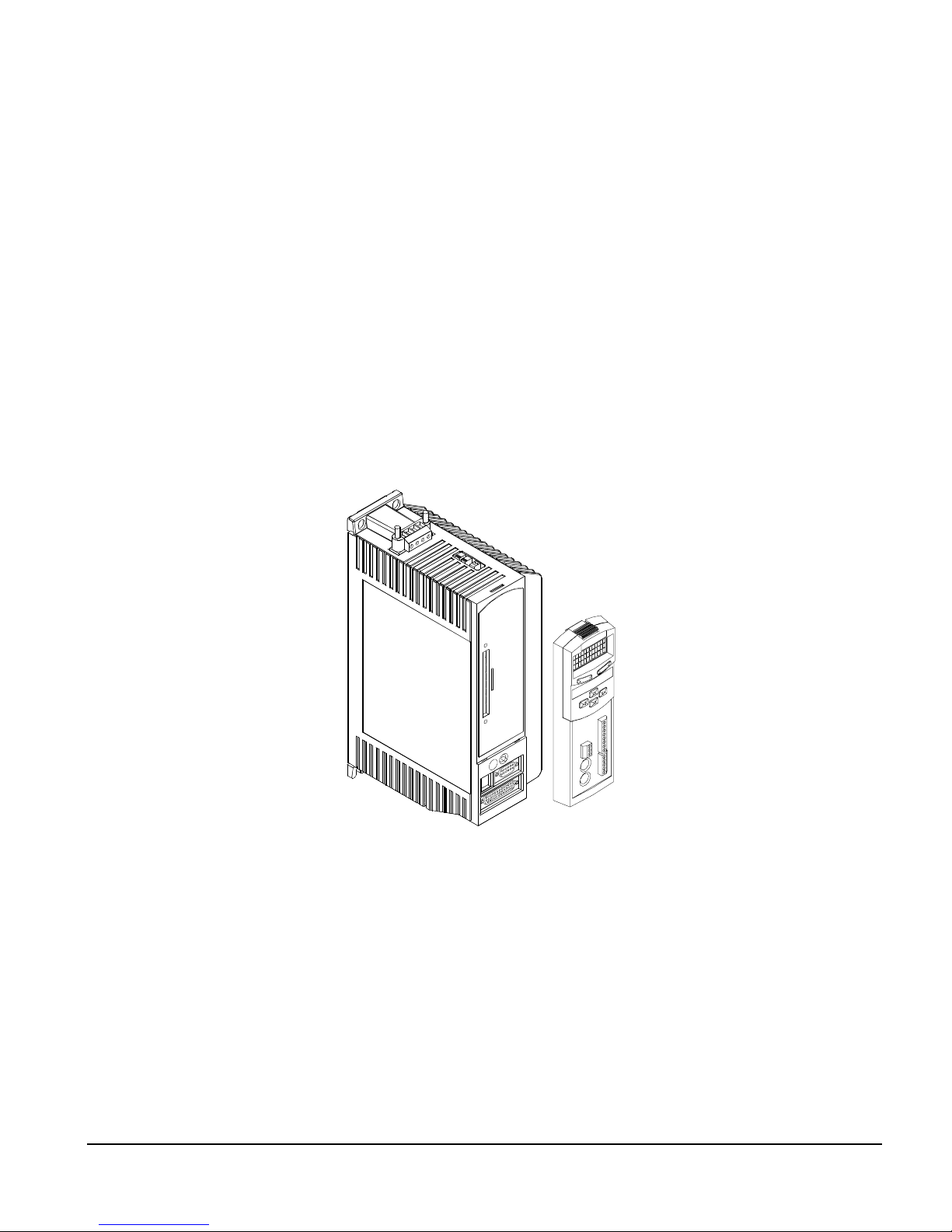
The FM-3 module is a compact and rugged function module that attaches to the front of the
drive. It provides eight digital input lines and four digital output lines, in addition to the four
input and three output lines available on the drive.
Unlike other function modules, the FM-3 module offers complex motion profiling. A
complex motion profile consists of two or more indexes that are executed in sequence such
that the final velocity of each index except the last is non-zero. Logical instructions between
index statements can provide a powerful tool for altering motion profiles "on the fly". The
FM-3 module defines complex motion by a configuration file that includes setups, function
assignments and programs . The configuration file is created using PowerTools Pro software
Setup views have the same look and feel as dialog boxes. The wiring of input and output
functions is done through assignments in the software. PowerTools Pro is an easy-to-use
Microsoft® Windows® based setup and diagnostics tool.
1
.
Figure 1: EN Drive with FM-3 Function Module
Note that the drive’s firmware is disabled whenever a Function Module such as the FM-3
module is attached. Therefore, if the drive’s hardware is FM compatible, then the drive’s
firmware can be any version because the programming features reside in the function
module’s flash memory. Flash files used fo r firmware up grad es are available on the Control
Techniques webpage.
The FM-3 module stores drive setup parameters within the module itself. This allows you to
transfer the FM-3 module to another drive without losing setup parameters.
1.In this manual, Emerson Motion Control PowerT ools Pro software will be refer red to as PowerTools Pro.
1
Page 16
FM-3 Programming Module Reference Manual
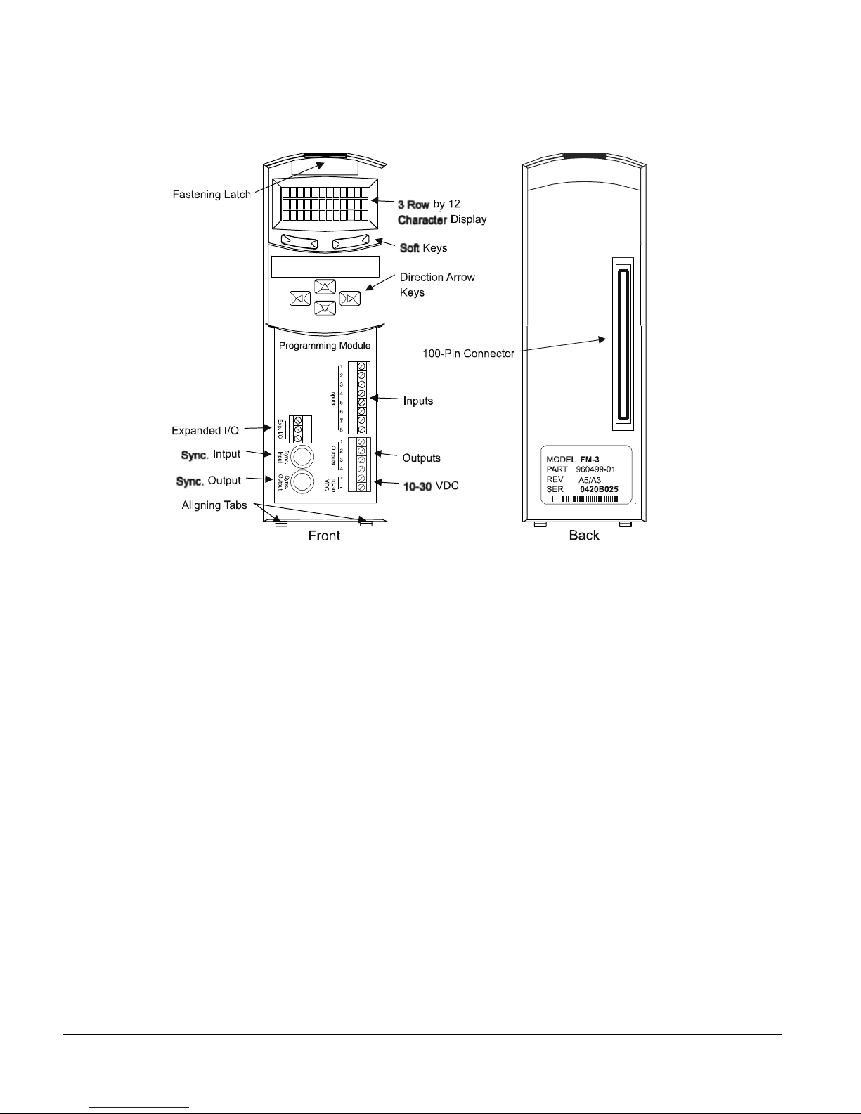
Figure 2: FM-3 Programming Module Features
2
Page 17

FM-3 Programming Module Reference Manual
Operational Overview
This section provides a complete functional description of the FM-3. It is intended to provide
you with a thorough understanding of all operations. The description includes references to
many FM-3 module and drive parameters which can be displayed and/or edited using
PowerTools Pro software, or through any Modbus interface.
The FM-3 module augments the drive by providing the ability to implement programs written
using PowerTools Pro. When a FM-3 module is attached to an drive, it overrides the operation
and user accessible features o f the d rive. The drive’s basic operating modes (Pulse, Velocity
and Torque) are not available when a F M-3 module is attached.
The FM-3 module stores drive setup parameters within the module itself. This allows you to
transfer the FM-3 module to another drive without losing setup parameters.
The FM-3 module allows you to set up 55 different indexes, Jog functions and mult iple
Homes. It also provides eight digital input lines and four digital output lines in addition to the
four input and three output lines available on the drive.
Software Interface
The FM-3 module is set up using PowerTools Pro software. PowerTools Pro is an easy-to-use
Windows® based setup and diagnost ics tool. It provides you with the ability to create, edit
and maintain your drive’s setup. You can download or upload your setup data to or from a
device. You can also save it to a file on your PC or print it for review or permanent storage.
PowerTools Pro Setup Software
PowerTools Pro is designed to be the easiest to use software available for single axis motion
controllers.
Features
• “Hierarchy View” for quick navigation to any setup screen
• Simple I/O function assignments
• Powerful online diagnostic capabilities
•Programming
3
Page 18
FM-3 Programming Module Reference Manual
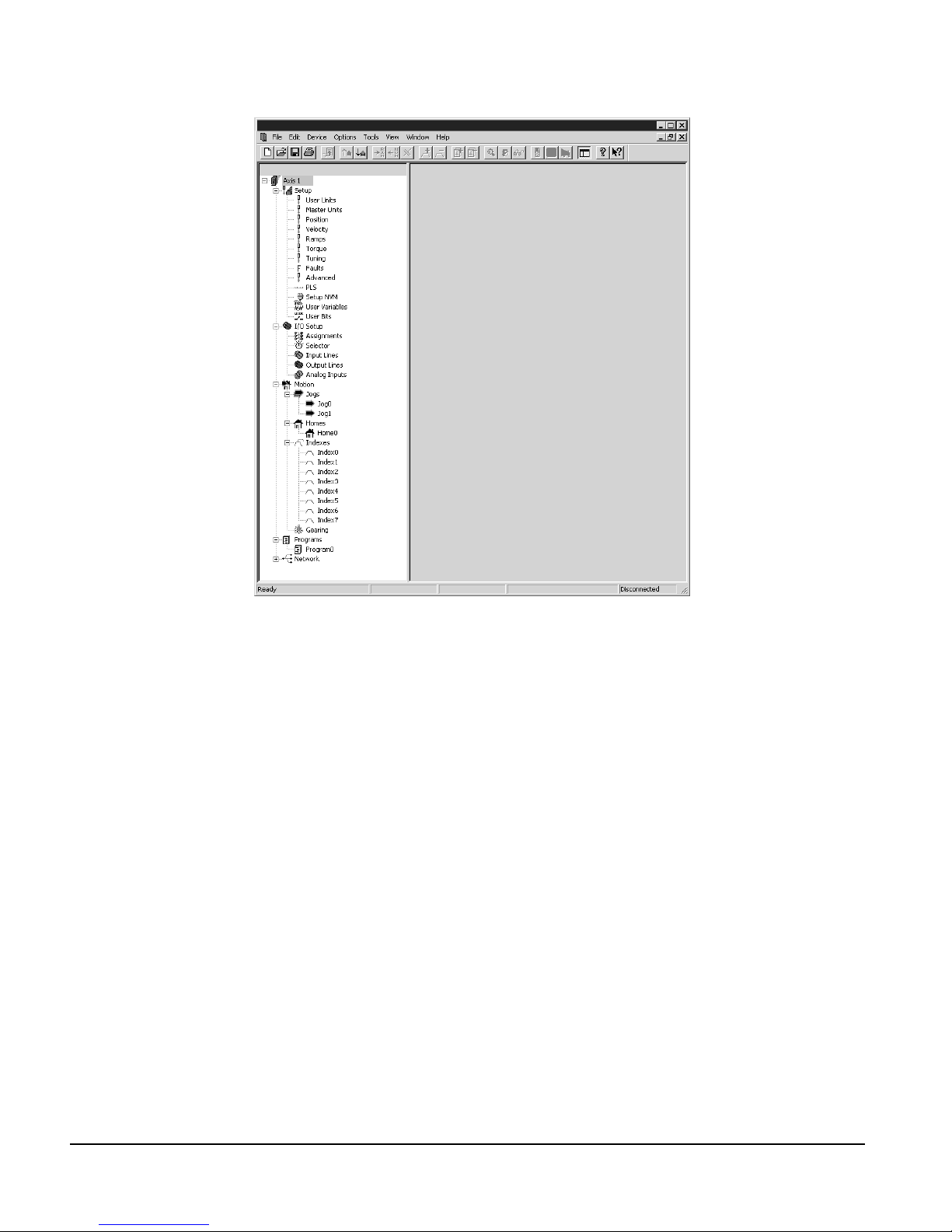
Figure 3: Hierarchy View
The “Hierarchy View” (sho wn above) contains expa ndable groups of parameters. The groups
can be expanded and contracted just like folders in Windows Explorer. Left clicking on a
view name in the Hierarchy view dis plays that View on the right side of the comp uter scr een.
To setup a drive the user simply steps through the Hierarchy View from top to bottom.
Simple applicati ons can be set up in a matt er of mi nutes. Many of t he views have Assignm ent
tabs that display t he assignments pertaining to the view (i.e. on the Positio n view, the position
assignments are displayed).
Keypad Interface
The keypad on the f ront of the FM-3 module provides navi gation through a menu of common
parameters and displays of current functions. Navigation through the menu is accomplished
with the six keys located below the display. The top two keys are called the "soft keys"
because they relate to the comm ands located directly above each key on the LCD. These keys
are used to select the operation (e.g. Mo dify, Ok, Cancel), parameter grou p, and/or to validate
information. The four arrow keys are used to navigate through parameter groups, select a
specific parameter to be modified, and to modify digital and numeric data.
The operation of the arrow keys is dependent upon the type of parameter which is being
modified.
4
Page 19
Operational Overview
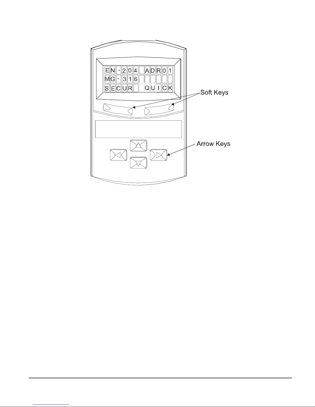
Figure 4: FM-3 Display Screen and Keypad
On the Menu screen, the drive type and axis address are always shown on the top line of the
display. The second line shows the motor type. If a user defined motor is selected, the user
defined motor name will appear. The third line shows two parameter group names, one above
each of the soft keys.
From the Menu screen, the user selects a group of drive parameters to wor k wi t h. The g rou p
names are scrolled using the left/right direction keys. The groups correspond roughly to the
tabs used by the PowerTools software. The groups are shown cyclically and wrap around.
The drive parameters available with the FM-3 keypad ar e arranged into seven grou ps (see list
below). Upon power-up the FM-3 module will display the default parameter groups
“SECUR” (left soft key) and “QUICK” (right soft key).
• QUICK (Quick)
• PROG (Program)
• INDEX (Index)
• HOME (Home)
• JOG (Jog)
• RAMPS (Ramps)
• SECUR (Security)
5
Page 20

FM-3 Programming Module Reference Manual
Security: 1
Screen
EN-204 Adr01
MG-316
SECUR
Menu
PBus-
Group
Slave Address
MODIF MENU
Security: 1
Baud Rate
MENU
Security: 0
Network Sts
MENU
Security: 0
Module Sts
MODIF MENU
Security: 0
MasterAddr
MENU
Security: 0
MsgProcessed
MENU
Security: 0
DVNET+
Group
MacID
MODIF MENU
Security: 1
Baud Rate
MODIF MENU
Security: 1
Security: 1
Network Sts
MENUMODIF
Security: 0
Module Sts
MENU
Security: 0
Net OK
MENU
Security: 0
Conn Type
MENU
Security: 0
Mster MacID
MENU
Security: 0
Transmit Cntr
MENU
Security: 0
Receive Cntr
MENU
Security: 0
SECUR
Group
Auto Log Out
MODIF MENU
Security: 3
Password 1
MODIF MENU
Security: 3
Password 2
MODIF MENU
Security: 3
Log Out Now?
OK
Security: 0
* Jog Group contains 2 Jogs (Jog.0 and Jog.1)
Index Group contains 7 Indexes (Index.0 to Index.7)
Prog Group contains 4 Programs (Prog.0 to Prog.3)
+ DeviceNet Group is only available on FM-3DN and FM-4DN modules
- Profibus Group is only available on FM-3PB and FM-4PB modules
On all screens with < > symbols, scroll left and right to select the specific Instance
RAMPS
Group
Stop
MODIF MENU
Security: 0
Stop.Decel
MODIF MENU
Security: 1
JOG*
Group
<Jog.0.Vel>
MODIF MENU
Security: 1
<Jog.0.Accl>
MODIF MENU
Security: 1
<Jog.0.Decl>
MODIF MENU
Security: 1
<Jog.0.Plus>
MODIF MENU
Security: 1
<Jog.0.Mius>
MODIF MENU
Security: 1
Posn Fdbk Ct
MENU
Security: 0
HOME
Group
Home.0.Vel
MODIF MENU
Security: 1
Home.0.Accl
MODIF MENU
Security: 1
Home.0.Decl
MODIF MENU
Security: 1
Home.0.Init
MODIF MENU
Security: 1
Calc Offset
MENU
Security: 1
Spec Offset
MODIF MENU
Security: 1
Select Offst
MODIF MENU
Security: 1
INDEX*
Group
<Ind.0.Vel>
MODIF MENU
Security: 1
<Ind.0.Accl>
MODIF MENU
Security: 1
<Ind.0.Decl>
MODIF MENU
Security: 1
<Ind.0.Dist>
MODIF MENU
Security: 1
<Ind.0.Init>
MODIF MENU
Security: 1
PROG*
Group
<Prg.0.Init>
MODIF MENU
QUICK
Group
Posn Fdbk
GRAPH MENU
Security: 0
Vel Fdbk
GRAPH MENU
Security: 0
Following Er
GRAPH MENU
Security: 0
Axis Address
MODIF MENU
Security: 0
Baud Rate
MODIF MENU
Security: 3
DriveInput
MENU
Security: 0
ModuleInput
MENU
Security: 0
DriveOutput
MENU
Security: 0
ModuleOutput
MENU
Security: 0
Fault Sts 1
MENU
Security: 3
Fault Sts 2
MENU
Security: 0
Clear Fault?
OK MENU
Security: 0
Module Rev
MENU
Security: 0
Boot Rev
MENU
Security: 0
Parameter Screens
After selecting a group using one of the soft keys, the FM-3 module will display a Parameter
screen for that group. This screen could be either the first screen in the group or the last screen
you used in that group. The FM-3 module keeps track of the last Parameter screen viewed in
6
Page 21

each group and returns to that screen when you come back to the group. This is reset on
power-up and the FM-3 keypad displays the first Parameter screen in the group.
In this screen, the parameter name is shown on the first line of the display. The up/down arrow
keys are used to scroll through the parameters available in the selected group.The second line
displays the condition or value of parameters. The third line displays the soft key actions.
The left/right arrow keys are used to scroll through the parameters when the “<“ and “>”
symbols are shown.
Numeric parameter units are sometimes shown before the actual value, because the parameter
value and the units cannot be displayed on one line. The unit of measure will appear on the
second line for about one second. Then the actual parameter value will appear. The parameter
value is updated about five times a second.
How Motion Works
The FM-3 module provides four types of motion: jogging, homing, indexing, and gearing.
Only one index, jog, home, or gear may be in process at any given moment (exclusionary
motion types). Through assignments and programs, the FM-3 module can sequentially run
various motion routines. The Positive direction parameter af fect s all m otion types by
specifying which direction of motor revolution (CW or CCW) is considered motion in the “+”
direction.
Operational Overview
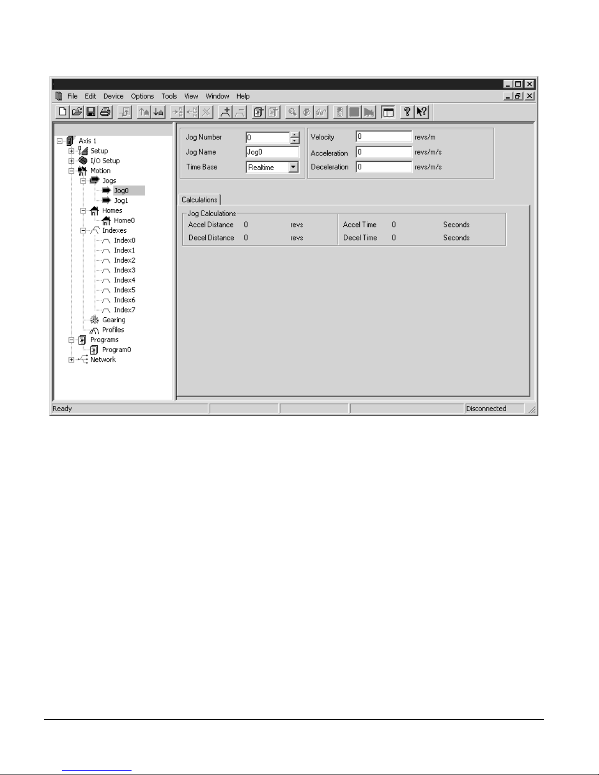
How Jogging Works
Jogging produces rotation of the motor at controlled velocities in a positive or negative
direction.
Assignments to jogs are level sensitive such that when the jog input is turned on, jogging
begins and continues jogging until the jog input is removed.
Each jog has its own acceleration and deceleration ramp along with a specified velocity.
Jogging has no distance parameter associated with it. If trying to move a specific distance
or to a known position, then an index is used.
7
Page 22
FM-3 Programming Module Reference Manual
Figure 5: Jog Tab
How Home Works
The Home is used in applications in which the axis must be precisely aligned with some part
of the machine. The Home is initiated in one of three ways: with the Initiate Destination
function found in the Ass ignments view, throu gh a program, or with t he Online tab. A Home
or Define Home is required to set the Absolute Position Valid so that any index to absolute
position can work.
The FM-3 module can home the motor to an external sensor, the motor’s encoder marker
pulse, or to a sensor and then to the encoder marker pulse.
8
Page 23
Operational Overview
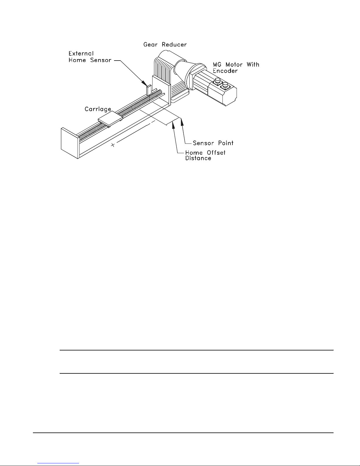
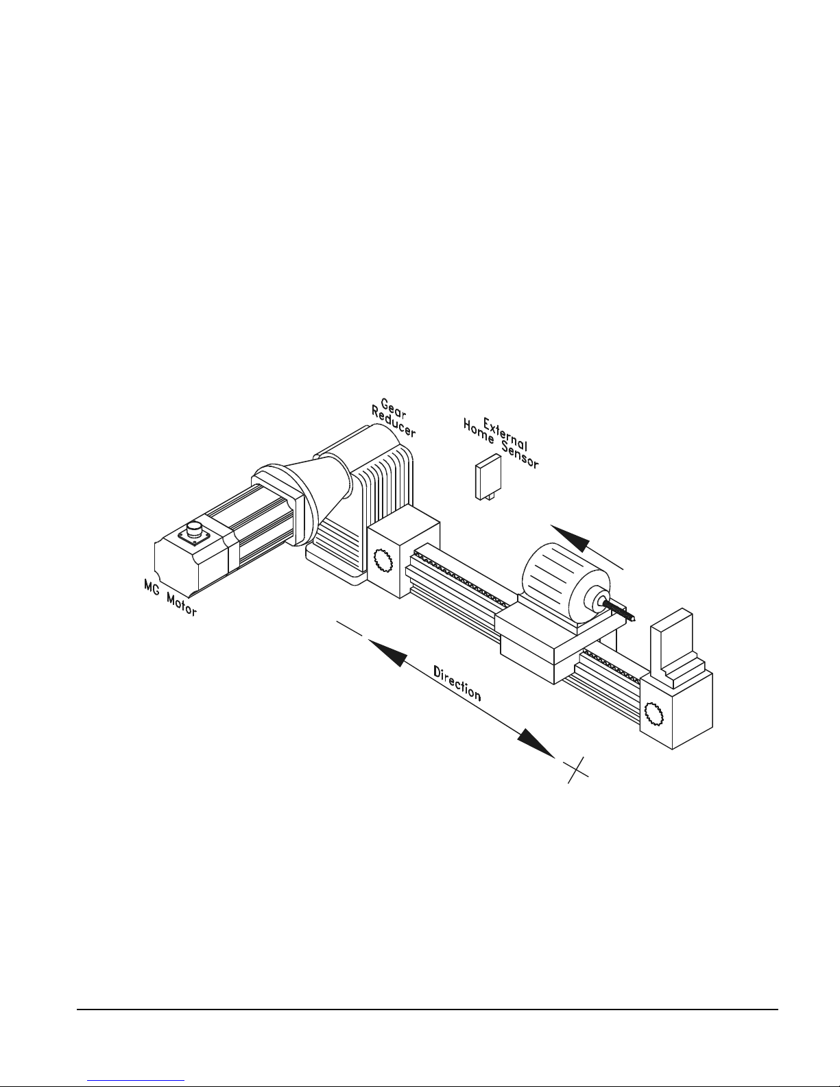
Figure 6: Basic Home Function, Example
The figure above show a basic home f unction us ing a ball scr ew. This examp le us es most o f
the setup features in the PowerTools Pro Home tab.
Home Sequence
1. Back off the sensor (if on the sensor. This step is optional).
2. Move to the external home sensor to establish a home reference point.
3. Next it will move to the Offset position.
4. Then the command and feedback positions are set to the value entered into the End of
Home Position.
Homing to the motor’s encoder marker will establish the most accurate and repeatable home
position. This method will position the motor relative to the location of the rising edge of the
encoder marker pulse. Most applications will use a sensor and marker to find an accurate
home position in the vicinity of the home sensor.
Several parameters affect how the Home function operates. Each of these parameters are
explained in detail on the following pages.
Note
The Home function will NOT be initiated when any other motion command is in progress .
Establishing a Home Reference Position
The first step in setting up a home is to select the desired home reference type. The Home
Reference parameter selected determines how the Home Refe r e nce Position is established.
9
Page 24
FM-3 Programming Module Reference Manual
PowerTools Pr o allows selection o f one of three diff erent Home References: Sensor, Marker,
or Sensor and Marker.
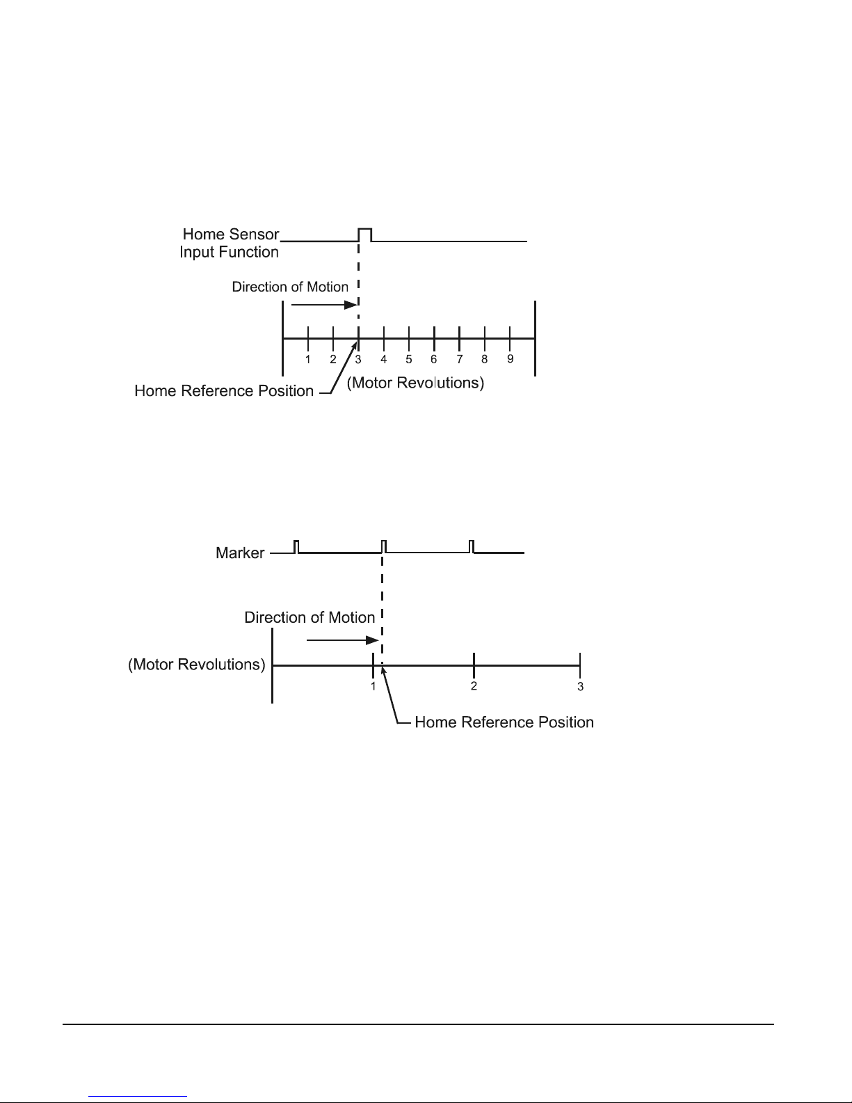
Sensor
Selecting Sensor means the ri sing edge of the Home Sensor inpu t function is used to establish
the home reference position.
Figure 7: Sensor Home Reference Position
Marker
Selecting Marker means the rising edge of the motor’s encoder marker channel is used to
establish the reference position.
Figure 8: Marker Home Reference Position
10
Page 25
Operational Overview
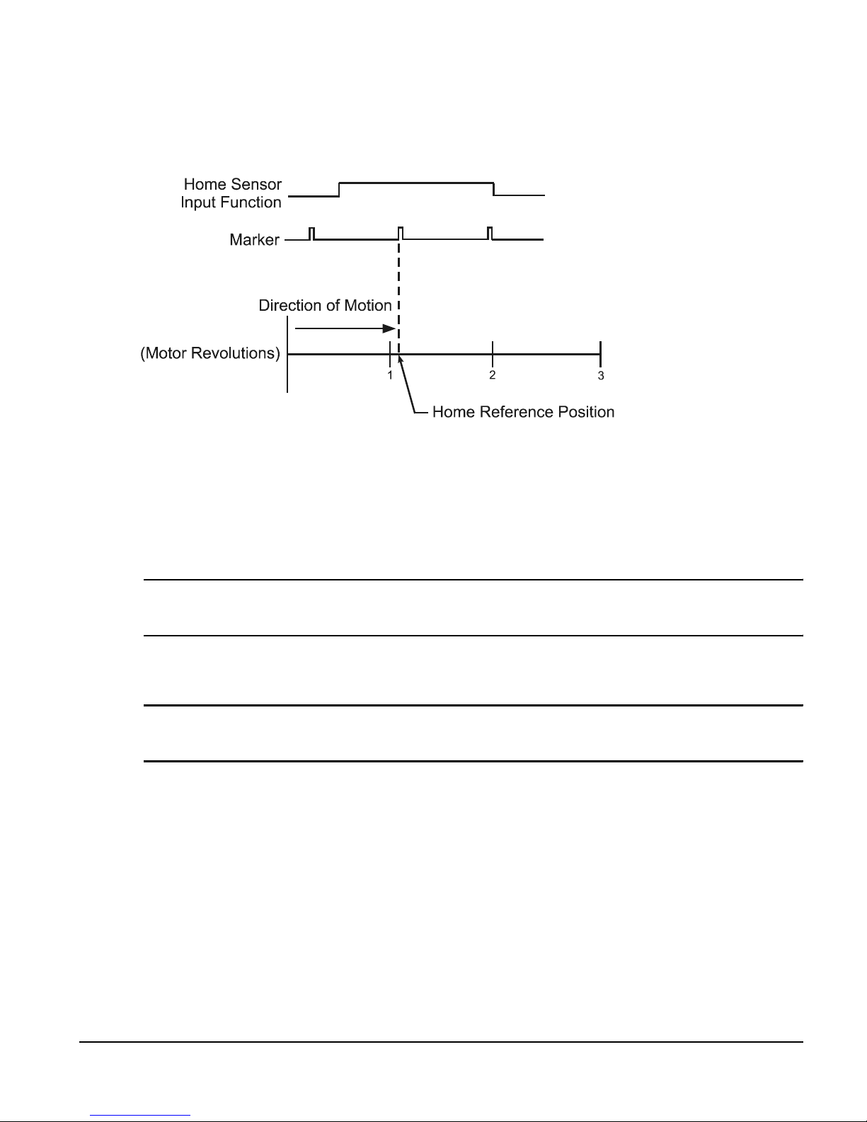
Sensor and Marker
Selecting Sensor and Marker means the reference position is establis hed using the first
marker rising edge after the device sees the rising edge of the Home Sensor input function.
Figure 9: Sensor and Marker Home Reference Position Example 1
Accuracy and Repeatability
The amount of accuracy your application requires will determine the Home Reference option
you select. Homing to an external sensor only will establish a repeatable home position within
0.04 revolutions at 3000 RPMs (800 µsec sensor capture interval).
Note
The data above assumes the use of a perfectly repeatable home sensor.
In Sensor and Marker app lications, the mar ker must be at least 8 00 µsec after the rising edge
of the sensor input to be considered a valid marker pulse.
Note
At 1000 RPM, the motor will travel 0.0133 revolutions (or 4.8°) in 800 µsec.
11
Page 26

FM-3 Programming Module Reference Manual
Sensor Min.
800 µsec
Sensor
Marker
Direction of Tr avel
Figure 10: Sensor and Marker H ome Reference Position Example 2
The Home Sensor must be “On” for at least 800 µsec to guarantee that it will be recognized.
Figure 11: Sensor and Marker H ome Reference Position Example 3
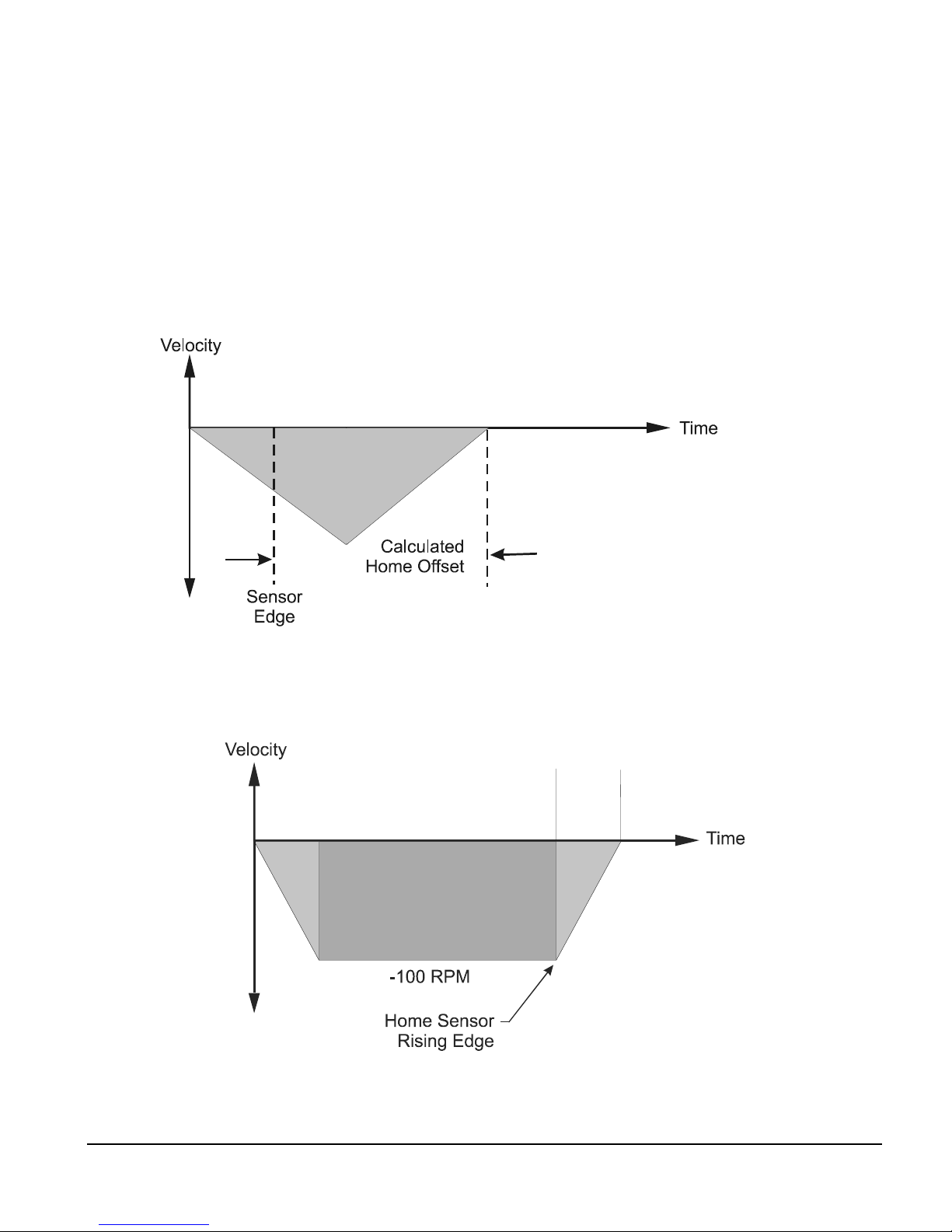
Home Offset
The Home Offset is the distance from the Reference Position to the final stopping point at the
end of the homing sequence. Regardless of the value you enter for the Offset or which Home
Reference you choose, there is always an offset inherent in the homing process.
The user may either specify a desired offset or allow the drive to calculate an offset
automatically. The drive calculates an offset that guarantees that the motor will not have to
backup to get to the offset position. This is very convenient for unidirectional applications.
On Time
Sensor
800 µsec
The calculated offset is the distance travelled during deceleration ramp from the home
velocity to a stop plus the distance travelled at the home velocity for 800 µsec. This extra
distance is used to guarantee that the motor will not need to backup after the deceleration
ramp.
12
Page 27
Operational Overview
Calculated
The Specified Offset allows the user to choose an exact offset from the Home Reference.
Once the home reference is detected, the device will do whatever is necessary to reach the
offset position. This may be as simple as a deceleration to a stop, a continuation at speed
followed by a deceleration to a stop, or a deceleration followed by a move in the opposite
direction.
To enter a specified home offset, select the Specified Offset radio button. PowerTools Pro
always displays the calculated offset value as a reference. If the home reference is detected
before the axis has reached its peak velocity, the axis will still co nti nue to the precise offset
position.
Figure 12: Calculated Home Offset, Peak Velocity Not Reached
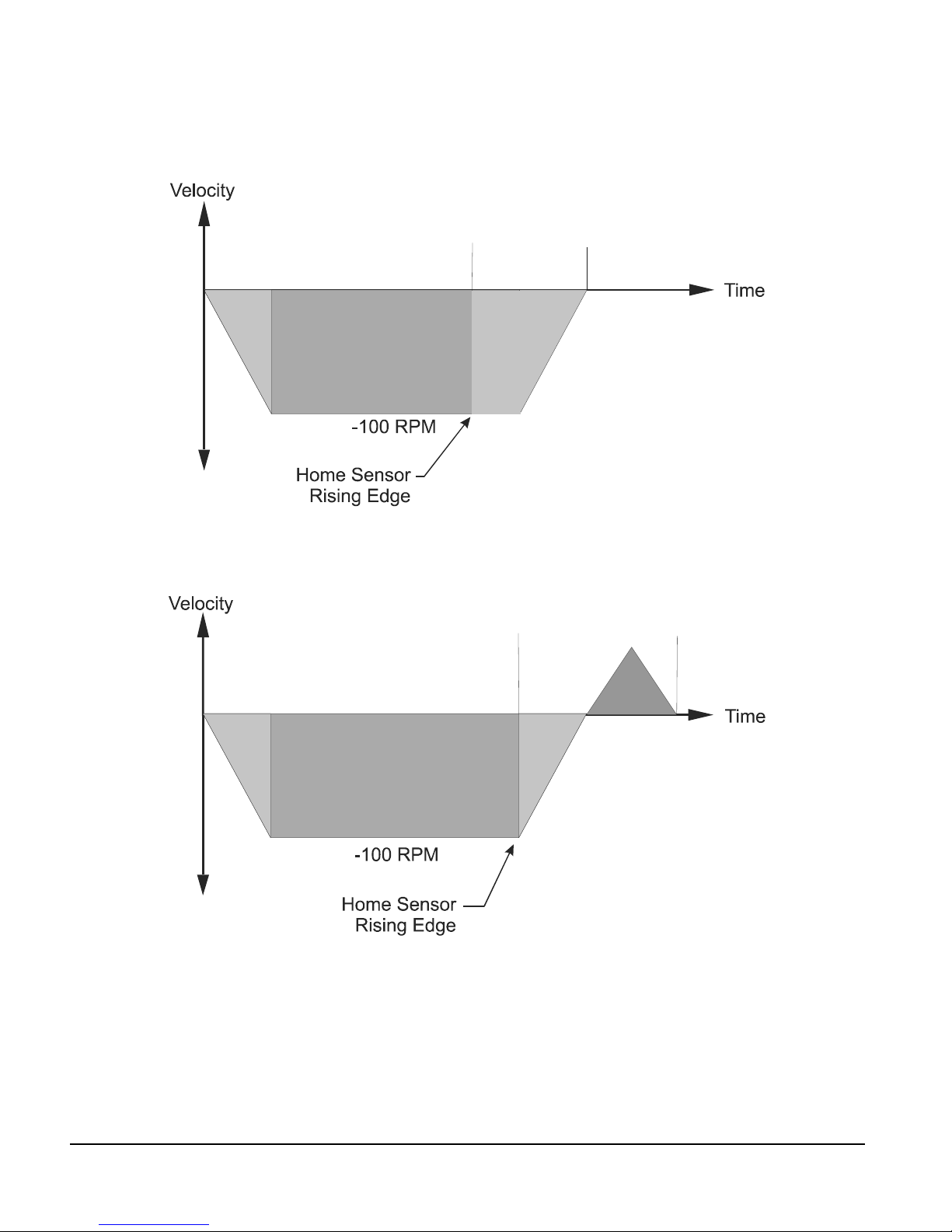
If the Home Reference is detected after the axis has reached its peak velocity, the axis will
decelerate to the precise offset position.
Home Offset
Figure 13: Calculated Home Offset, Peak Velocity Reached
13
Page 28
FM-3 Programming Module Reference Manual
Two examples below show operation when the specified offset is greater or less than the
calculated offset. This causes the axis to continue on at speed before decelerating and
stopping at the offset position, or backing up after the home sensor.
Specified
Offset
Figure 14: Specified Home Offset, Greater than Calculated Offset
Specified
Offset
Figure 15: Specified Home Offset, Backup Required
End of Home Position
The End of Home Position (End Posn) defines the home position in relation to the machine’s
coordinate system. At the completion of the home, the value of the End of Home Position is
put into the command position.
14
Page 29
Home Limit Distance
This parameter places an upper limit on the incremental distance the motor will travel during
the home.
If no reference is found, the system will decelerate and stop at the limit distance. The Home
Limit Distance Hit function will be activated if the home stops at the limit d istance without
finding the reference. Additionally, the Home.CommandComplete f unc tio n will not turn
“On” if the limit distance is hit.
Home Examples
Example 1: Linear Application
In this example, the system uses an external sensor and the motor’s encoder marker channel
to establish a Home Reference Position. This is the most accurate and most common way to
home.
Operational Overview
Figure 16: Home to Sensor and M arker, Ex ample
When the FM-3 module sees the Home Initiate, it accelerates the motor to the Home Velocity.
The motor continues at that velocity until it first senses the Home Sensor in put. It continues
at the same velocity until the motor’s encoder marker channel is sensed. The rising edge of
the motor’s encoder marker chan nel is used to establish the reference position. Once the
home reference is detected, the motor decelerates to a stop and moves to the offset position.
15
Page 30
FM-3 Programming Module Reference Manual
n
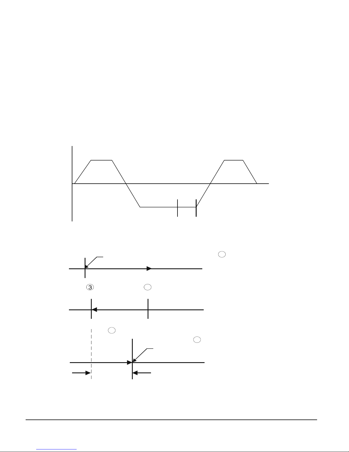
Home Sequence
1. If on sensor then back off (if enabled)
2. Search for se nsor
3. Search for marker
4. Go to offset (2.0 Revs)
5. Set feedback position equal to End of Home Position
Velocity
+ 100
Back off
Sensor
- 100
Figure 17: Home Velocity Profile
Start of Home
2
Marker
Sensor
Sensor
+ 100
Time
Marker
1
Back Off Sensor
Home Move
4
Offset Move
2.0 Revs
Offset
Figure 18: Home Move Sequence
16
5
Final Position = End of Home Positio
Page 31

Operational Overview
Example 2: Rotary Application
This example uses an external sensor and the motor’s encoder marker pulse to establish a
home reference position.
Figure 19: Home Sensor and Marker then Offset, Example
When the device sees the rising edge of the Home Initiate function, it accelerates the motor
to the Home Velocity. The motor continues at that velocity until it first senses the Home
Sensor input. The motor continues on at the home velocity until the marker is activated.
The rising edge of the motor’s encoder marker channel is used to establish the reference
position.
After sensing th e rising edge of the mo tor’s marker channel, the dev ice will cont inue movi ng
and will decelerate to a stop at the specified offset position.
Figure 20: Home Velocity Profile
17
Page 32

FM-3 Programming Module Reference Manual
How Indexes Work
An index is a complete motion sequence that moves the motor a specific incremental distance
or to an absolute position. This motion sequence includes an acceleration ramp to a
programmed velocity, a run at velocity, and a deceleration to a stop.
Velocity
Run at Velocity
Acceleration
Figure 21: Index Moti on Sequence
Deceleration
Time
18
Page 33

Operational Overview
Figure 22: Indexes View
Indexes use acceleration and deceleration ramps which may or may not reach the specified
velocity depending on the total distance and the ramp values. For example, a short move with
long acceleration and deceleration ramps may not reach the target velocity entered.
Indexes cannot be initiated when any other motion (jogging, homing, or program) is in
progress. Indexes can be aborted with the Stop destination found in t he Ramps group on the
Assignments View.
The FM-3 module supports five types of indexes: absolute, incremental, registration, rotary
plus and rotary minus.
19
Page 34

FM-3 Programming Module Reference Manual
Absolute Index
Absolute Index
Absolute vs. Incremental
The difference between absolute and incremental index e s is that absolute indexes move to a
specific absolute position and incremental indexes move the motor a specific distance. The
figures and explanations below demonstrate this concept.
Absolute Indexes
Absolute indexes are used in applications where the motor must trav el to a s pecific po sition,
regardless of where the motor is when the index is initiated.
The FM-3 module calculates the distance required to mov e to t he spe cif ied p ositi on f rom the
current position.
Absolute Index
Start Position = 1 Rev
Index Position = 5 Revs
Figure 23: Absolute Index Example 1
In the example above, the current position is 1 rev. If this index is initiated, the motor will
travel to a position o f 5 revs no m atter where it i s sitting bef ore the move. Fr om 3 revs, i t will
travel 2 revs to finish at 5 revs. If the absolute index to 5 revs is initiated a second time
immediately after the index, no motion will occur because the motor will already be at a
position of 5 revs.
The direction of an Absolute Index is determined by the starting position and the absolute
index position. If the starting position for the above index is 9 revs, then the motor will rotate
in the negative direction to end up at 5 revs. The diagram below shows this.
Start Position = 9 Revs
Index Position = 5 Revs
Figure 24: Absolute Index Example 2
20
Page 35

Operational Overview
Incremental Index
Incremental Index
Absolute indexes with Rotary Rollover enabled wi ll take the shortest path to the position
entered in the index position parameter.
Note
Absolute indexes move to positions re lative to where the machine was homed using the
Home, or the DefineHome destination.
Incremental Indexes
An incremental index will move the motor a specified distance in the + or - direction
regardless of the starting position. The directio n of the incremen tal index motion is
determined by the sign (+ or -) of the Index Distance parameter.
Incremental Index
Start Position = 1 Rev
Index Distance = 2 Revs
Figure 25: Incremental Index Example
In the example above, the motor starts at 1 rev, travels a distance of 2 revs and stop s at 3 revs.
If the same index is initiated a second time, the FM-3 module would move the m otor another
2 revs to a position of 5 revs. If initiated a third time, the motor would travel another 2 revs
to a final position of 7 revs. The example below shows this operation.
Figure 26: Incremental Index Example 2
Start Position = 1 Rev
Index Distance = 2 Revs
21
Page 36

FM-3 Programming Module Reference Manual
Registration Index
A Registration Index is used in applications where the motor must move until an object is
detected and then move a specific distance from the point of detection, such as finding a
registration mark and moving a distance beyond.
The Registration Index consists of two parts. The first part accelerates the motor to the target
velocity and continues at this velocity until it receives a registration trigger (sensor or analog).
Upon receipt of a registration trigger, the regis tration offset will be executed at the target
velocity. The Sensor Limit Distance Hit source can be used to turn on an output, if a sensor
input or analog limit is not received within the Limit Distance. A registration window can
also be used to determine the validity of a registration trigger. If a regi str a tion trigger is
received outside of the registration window, it will be ignored.
Rotary Plus and Rotary Minus Indexes
Rotary Plus and Rotary Minus Indexes provide forced directional control of moves to
absolute positions. The position entered for a Rotary Plus or Minus type index must be within
the rotary range (i.e. 0 ≤ Position < Rotary Rollover Point). All other parameters function the
same as they do with absolute indexes. An Absolute Index is a direct move to a specific
position, regardless of the starting point. A Rotary Plus Index moves to the specified position,
but is forced in a positive direction. Similarly, a Rotary Minus index moves to the sp ecific
position, but is forced in a negative direction.
Rotary Plus and Minus Indexes are usually used in rotary applications, therefore the rotary
rollover feature on the S etup - Positio n view in the Power Tools Pro softwar e must be enabled
to use them.
1. In the fo llowing examples the term “D” = (absolute position specified) - (current
position). If “D” is negative, motion in the negative direction is implied.
2. In the following examples the Rotary Rollover parameter on the Setup - Position view is
set to 360.00°. This means that with each revolution of the motor (or rotary table),
feedback will count up to 359.99°, then roll over to Ø°.
Indexes with Rotary Rollover Enabled
Incremental move distances can be outside of the rotary rollover range. See the Setting
Up Parameters section for an explanation of Rotary Rollover.
Example 1: If the starting position is at Ø° and 720° is the specified distance, an
Incremental index would move 2 revolutions in the positive direction. At the completion
of this index the motor position would be Ø°.
Absolute indexes will take the shortest path to the specified position. Absolute index
positions must be within the rotary rollo ver r a nge.
Example 2: If the starting position is at 90° and 80° is the specified position, an Absolute
index would travel 10° in the negative direction. At the completion of this index the
motor position would be 80°.
22
Page 37

Operational Overview
Example 3: If the starting position is 45° and 315° is the specified position, an Absolute
index would travel 90° in the negative direction because that is the shortest path between
45° and 315°.
Rotary Plus indexes will move to the specified position and are forced in a positive (or
plus) direction. Rotary Plus index distances must be within the rotary rollover range.
Example 4: As in example 2 abov e, the starting position is at 90° and 80° is the specified
position. A Rotary Plus index would travel 350° in the positive direction. At the
completion of this index the motor position would be 80°.
Example 5: If the starting position is 10° and the specified position is 350°, a Rotary Plus
index will travel 340° in the positive direction.
Rotary Minus indexes move to the specified position, but are forced to travel in the
negative (or minus) direction. Rotary Minus index positions must be within the rotary
rollover range.
Example 6: As in examples 2 and 4 above, the starting position is at 90° and 80° is the
specified position. A R ot ary Mi nus index would travel 10° in the negati ve di rect ion. A t
the completion of this index the motor position would be 80°.
Example 7: If the starting position is 15° and the specified position is 270°, a Rotary
Minus index would travel 105° in the negative direction.
How Communications Work
Uploading
Uploading is the process of reading information back from the drive to the PowerTools Pro
configuration screens.
To upload inform ation from a driv e, click on the upload button on the PowerTools Pro t oolbar
or select upload from the Device menu.
Downloading
Downloading is the process of s ending your co nfiguration created with PowerTools Pro from
the PC to the FM-3 module. Changes made in PowerTools Pro will no t take effect until th e
information has been downloaded or the Update to RAM button has been clicked.
To download information to a FM-3, click on the download button on the PowerTools Pro
toolbar or select download from the Device menu. Powe rTools Pro will lead the us er through
a series of dialog boxes that determine what baudrat e and which communicat ions port on the
user’s P C will be u s ed.
23
Page 38

FM-3 Programming Module Reference Manual
NVM Options for Uploading and Downloading
Uploading
When uploading from a FM-3 module, the values that were last downloaded are uploaded and
put into a PowerTools Pro configuration file. At the completion of the upload, the user will
be asked if they wish to upload the NVM values. This dialog box is shown below.
By selecting Yes, the values of all parameters stored in NVM will be uploaded and en tered
into the PowerTools Pro file values. If No is selected, the values entered into the PowerTools
Pro file will remain the same as those that were last downloaded to the FM-3 module.
Downloading
When downloading to the FM-3 module the user will be required to select how to handle the
NVM parameters upon downloading. The dialog box asking the user to select one of three
options for the download is shown below.
A description of each of the options is as follows:
Overwrite – This option will overwrite all the parameters stored in NVM with the current
values in the user configuration (PowerTools Pro file). The values that are in NVM prior to
the download will be lost.
Update – This option will upload the curre nt NVM parameter values from the FM-3 module
and enter them into the user configu ration (PowerTools Pro file). Once the NVM values have
been stored in the file, the file is fully downloaded.
Keep – This option will download the entire user configuration, but then NVM parameters
will be restored to the value prior to download. This is similar to the Update option, but the
24
Page 39

Operational Overview
Keep option does not upload the NVM values into the user configuration (PowerTools Pro
file).
The following table shows an example of how these options work:
PT Pro file value for
Index.0.Vel
NVM value for
Index.0.Vel
Updating to RAM
The Update to RAM button can be used to send changes to the FM-3 module without
performing a complete download. The Update to RAM button is found in the PowerTools Pro
toolbar. This operation will send only those changes that have been made since the last
Update to RAM or Device – Download to the FM-3. The changes will take effect
immediately upon clicking on the button.
Before
Download
150 150 500 150
500 150 500 500
Overwrite
Option
After Download
Update Option
Keep Option
The parameters will be sent to the FM-3 module without stopping motion or disabling the
drives. Because of this, it is important to use caution when changing motion par ameters
while the motor is in motion.
The Update to RAM button saves the parameters only to RAM and not to Non-Volatile
Memory (NVM). Therefore, if the system power is removed, any changes made using the
Update to RAM button will be lost. In order to save changes to NVM, a full-download must
be performed.
The flowchart below describes a typical process using the Update to RAM to make change s,
and then downloading when complete to save changes to NVM.
25
Page 40

FM-3 Programming Module Reference Manual
Figure 27: Update to RAM Flow Chart
The Update to RAM button operates according to the following rules:
If no parameters have been modified by the user, the Upd ate to RAM button will be disabled.
If the user modifies a parameter that does not require a full download, the Update to RAM
icon will be enabled.
If while the icon is enabled, the user modifies a parameter that requires a full download, the
Update to RAM icon will become disabled.
When the user clicks on the Update to RAM icon, all the modified parameters are transmitted
to the FM-3. Once transmitted, the icon will become disabled again until another parameter
is changed.
If the user performs a full download while the button is enabled, when the download is
complete, the Update to RAM button will be disabled.
If the user modifies parameters , and dis connects, the update button will be dis abled, and the
changes will not be sent.
Options/Preferences/Ptools Operation
This menu controls the pop-ups that the user encounters when uploading and downloading
the FM-3/4 configuration.
Download Section:
“Ignore saving file on Ptools/Drive revision conversion.”
On a download PowerTools Pro checks the firmware revision of the module that it is about
to be downloaded to and is required to make changes to the files that are to be downloaded to
older firmware revisions. This checkbox allows the user to avoid saving the newer file before
converting it to a previous revision.
“Overwrite – Reset the NVM configuration”
26
Page 41

Operational Overview
When this checkbox is selected the “Overwrite” function will default on ever y download to
the module. This function will overwrite the entire FM-3 configuration including user defined
NVM parameters as set in the NVM setup area of PowerTools Pro.
Note
It is required to Overwrite the Non-Volatile Memory on the first download to the module
since no Non-Volatile Memory parameters have been loaded into the drive on initial
startup.
“Update – Upload the values into the current Update PowerTools Pro configuration”
When this checkbox is selected the “Update” function will Update the NVM on every
dowload to the module. Upon download the Update function uploads the configured NVM
from the drive and places the data into the PowerTools Pro configuration file. The software
then downloads this newly updated file to the module.
“Keep – Remember the values and res tore them after the download”
This option was created to allow users to save the values that have been changed via HMI,
PLC or internally in a program so long as they have been added to the NVM list. When this
checkbox is selected PowerTools Pro will poll the drive on download for all of the values that
have been added to the NVM list. PowerTools Pro then stores these values into a temporary
memory location and after the program download is complete PowerTools Pro rein states
these values to the parameters before the drive can be enabled.
“Ask on each download”
This option was created for users who want control of whether they will overwrite or keep the
NVM on download. When this checkbox is selected, PowerTools Pro will display a pop-up
window that gives the user the option to Overwrite, Update, or Keep as described above.
Upload Section:
“Always convert Application to latest Ptool capabilit y”
When this checkbox is selected, PowerTools Pro will automatically update an uploaded file
to match the current functionality of PowerTools Pro.
"Always leave Application matching Module capability”
When this checkbox is selected, PowerTools Pro will default to upload and disp lay the
configuration to match the firmware revision and capabilities of the module.
“Ask on each upload”
When this checkbox is selected, PowerTools Pro will default to asking the user to convert the
application to the latest PowerTools Pro capability, or leave the application to match module
capability.
27
Page 42

FM-3 Programming Module Reference Manual
Upload Non-Volatile Memory (NVM) Section:
“Always upload NVM”
When this checkbox is selected, PowerTools Pro will default on an upload to uploading all of
the parameters that have been mapped to the NVM and updating the display of these
parameters in PowerTools Pro.
“Always bypass NVM upload”
When this checkbox is selected, PowerTools Pro will not upload the NVM and the values that
were originally downloaded to the drive will be displayed in the PowerTools Pro
configuration.
“Ask on each upload”
When this checkbox is selected, PowerTools Pro will default to asking t he u ser vi a a pop -up
window whether to upload the NVM or to bypass the NVM upload.
Secure Downloading
The Secure Download feature allows the user to download a configuration that prevents
anyone from uploading the file, or going online with the system. This is used to protect a file
from being accessed by unauthorized personn el. If a secure file is downloaded to the system,
all diagnostics capabilities in the software are lost. The only way to go online with the system
again is to download the origin al (non-secure) file over the secure version, or to download a
completely new file.
Before performing a secure download, the file must first be saved in the secure file format.
To do this, open the file you wish to save in the secure format using PowerTools Pro. Then
click File\SaveAs on the Menu Bar. The following SaveAs window should appear on your
screen
On this window, check the “Save also as secure download format” check box located at the
bottom of the window, then click on the Save button. Doing this will save your file in BOTH
28
Page 43

Operational Overview
the standard file format (. fm3), as well as in the secure file format (.fm3s) . The “s” at the end
of the file extension stands for “secure”. The secure file will be saved to the same directory
as the standard file.
To perform the Secure Download, close all open files in PowerTools Pro. Then click on
Device\ Secure Download on the menu bar as shown below.
A window will then pop up asking the user to select the secure file that they wish to download.
Select the secure file that was just saved, and then click on the “Open” button. This will
download the secure file to the target device.
A secure file (.fm3s) cannot b e opened o r modified . The file extens ion cann ot be changed to
allow the user to open it. The secure file is only valid for use by the secure download function.
If a user attempts to upload a secure file, a message will appear indicating that the file residing
in the system has been protected by the user. An example of this is shown below.
Brake Operation
MG motor brake operation is controlled by the Brake Release and Brake Control destinations.
These destinations can be used together to control the state of the Brake source. The table
below shows the relationship between the Brake sources and destinations (see “Diagnostic
Display”).
Note
No motion should be commanded while the brake is engaged.
Brake Release Destination Off On
Brake Ac tivate Destination On Off On Off
Drive Power
Stage
Enabled
Disabled
0111
0011
29
Page 44

FM-3 Programming Module Reference Manual
Brake Release
The Brake.Release destination function will release the brake under all conditions. When this
function is active, the Brake output will be on (that is, release brake). This function overrides
all other brake control, thus allowing the brake to be released while a fault is active or the
power stage is disabled. See also Brake source function.
Brake Acti va te
The Brake.Activate destination function, when active, will engage the brake unless
overridden by the Brake Release function. This function lets you externally engage the brake
while allowing the drive to also control the brake during fault and disabled conditions.
Brake Dise nga g ed
The Brake.Disengaged source function is used to control the motor holding brake. If the
Brake function is off, the brake is mechanically engaged. When the brake is engaged, the
diagnostic display on the front of the drive will display a “b”.
The drive outputs are limited to 150 mA capacity, therefore, a suppressed relay is required to
control motor coil. Control Techniques offers a relay, model # BRM-1.
30
Page 45

FM-3 Programming Module Reference Manual
Setting Up Parameters
Setup View
The Setup View contains all of the primary system setup parameters. These parameters mus t
be setup prior to using your system.
By selecting Setup in the Hierarchy View, the Setup view will appear on the right sid e of the
view (see Figure 28). The Setup view is divided into six groups, with an ex planation of each
function. The groups are Identification, Configuration, Drive Encoder Output, Positive
Direction, Update Rate and Switching Frequency. Status Online will be shown when online
with the FM-3 module.
Figure 28: Setup View
Identification Group
The identification group consists of the Device Name and the Target Drive Address.
31
Page 46

FM-3 Programming Module Reference Manual
EN
Name
This is a 12-character alpha/numeric user-configured name for this axis. Enter this name for
the device you are currently setting up. Assigning a unique name for each device in your
system allows you to quickly identify a device when downloading, editing, and
troubleshooting. All keyboard characters are valid. This will default to Axi s 1.
Target Drive Address
This is the Modbus address of the target drive to which you will download the configuration.
The default target drive address is 1.
Configura tion Group
The configuration gr oup consists of li st boxes for Drive Ty pe, Motor Type, and Lin e Voltage.
Drive Type List Box
Select the drive model for the system you are currently setting up.
Motor Type List Box
Select the motor you want to use.PowerTools Pro software will only display the motor models
that are compatible with the drive you selected and any user defined motors.
Selecting the wrong motor type can cause instability and may cause property damage to
the moto r and/or dr ive.
EN Only
Line Voltage List Box
Line Voltage specifies the applied power and adjusts the internal gains to compensate for
it. This parameter has two choices: 115 VAC and 230 VAC. If the Line Voltage is set to
230 VAC when the actual applied voltage is 115 VAC, the motor will be slig htly less
responsive to commands and load disturbances.
The Line voltage must never be set to 115 VAC if the applied voltage is actually 230
VAC. This can cause drive instability and failure, resulting in property damage.
Drive Encoder Output Group
The drive encoder output group consists of the encoder scaling check box and encoder
scaling.
32
Page 47

Encoder Scaling Check Box
This check box enables the Scaling parameter of the Drive Encoder Output.
Encoder Scaling
This parameter defines the encoder resolution (lines per re volution) of the drive's encoder
output. This feature allows you to change the drive encoder output resolution in increments
of 1 line per revolution up to the density of the encoder in the motor. If the Encoder Output
Scaling parameter is set to a value higher than the motor encoder density, the drive encoder
output density will equal that of the motor encoder.
Positive Direction Group
The Positive Direction group consists of a clockwise (CW) Motor Rotation Radio Button or
a counter-clockwise (CCW) Motor Rotation Radio Button.
The motion will move in either CW direction or counter-clockwise CCW direction.
Perspective of rotation is defined as you face the motor shaft from the front of the motor.
CW Motor Rotation Radio Button
Setting Up Parameters
Select this radio button for applications in which CW motor rotatio n is consid er ed to be
motion in the positive direction (increasing abso lute position).
CCW Motor Rotation Radio Button
Select this radio button for applications in which CCW motor rotation is co nsidered to be
motion in the positive direction (increasing abso lute position).
Update Rate Group
This parameter configures the interrupt interval for the FM-3 processor. This defines how
often the motion program is interrupted and the Control Lo op is processed. In the Control
Loop, the feedback information is processed and a new position command is generated. Also
in the Control Loop, the I/O is scanned. After Control Loop is complete, all messages are
handled. Messages are Modbus data, DeviceNet data, Keypad/Display information, and are
only processed if a message is wai ting. If no device is querying data from t he FM-3 or sending
data to the FM-3, then messages do not take up any time. Once messages have been
processed, the remainder of the int errupt is dedi cated to runni ng the motion programs of user
programs.
Available selections for Trajectory Update are 800, 120 0, and 1600 microseconds. The l onger
the update, the more time is dedicated to the user programs, and the less time dedicated to
servo performance. Th e shorter the updat e , the mor e precis e the servo perform ance, b ut less
time is available to process user progra ms. Diagnostics are available on the Status Online tab
when online with the device to help select the ideal setting. (See description of Control Loop
Group of online parameters for further information)
33
Page 48

FM-3 Programming Module Reference Manual
Switching Frequ ency Group
This parameter defines the s witching frequency of the electro nic amplifier. For EN drives, the
switching frequency must be 20 kHz and cannot be changed. For MDS, the switching
frequency can be modified to change system performance. Available selections are 5 kHz,
and 10 kHz. For more information on this setting refer to the MDS Reference Manual, P/N
400525-01.
Status Online Tab (Online Only)
The Status Online tab (s ee Figure 29) is visible when online and consists of the Motor
Position group, Motor Velo city gr oup, C ontro l Loop g roup, Mas ter Feedb ack grou p, and the
Torque group.
Figure 29: Setup View - Online Status Tab
34
Page 49

Motor Position Group
Position Command
Position command is the commanded motor position sent to the drive by the FM-3 module.
This parameter does not take following error into account. See also PosnFeedback and
FollowingError. Units are in user units.
Position Feedback
Feedback position is the actual motor position in user units. PosnCommand minus the
PosnFeedback is the FollowingError
Following Error
The Following Error is the difference between the Position Command and the Position
Feedback. It is positive when the Position Command is greater than the Positio n Feedb ack.
Encoder Position
Motor encoder position in encoder counts. This position reflects the feedback position of the
motor and is not scaled into user units. This is a signed 32 bit value.
Setting Up Parameters
Motor Veloci ty Group
Velocity Command
The Velocity Command is the velocity that the FM-3 module is commanding the motor to run
at. This command is generated by the drive velocity control loop and position loop. It is
displayed in user units.
Velocity Feedback
This is the feedback (or actual) velocity. It is calculated using the change in position of the
motor encoder. It will always return the actual motor velocity - even in synchronized
applications in which the master axis is halted during a move.
Control Loop Group
Changing the Trajectory Update Rate can have a major effect on the performance of your
servo system. A longer trajectory update rate mean s that more time is available to process user
programs. A shorter update rate means that the control loop is updated more often and
provides the most accu rate p erfo rmance. W ithout pro per diagnostics, it can be impossible to
tell how much time is being consumed by the control loop update, and how much time is
available to run user programs.
The Control Loop group of parameters on the Status Online tab shows the user how much
time is available to run programs. There are two parameters available to help with this. They
are as follows:
35
Page 50

FM-3 Programming Module Reference Manual
Control Loop Limit
This parameter shows the lowest measured time difference (in microseconds) between the
Trajectory Update Rate and the time taken to process the control loop since the last reset.
Certain features in the FM-3 require more time to process (i.e. PLS, Capture, Compound
Indexes), and therefore will cause lower limits. The software records the lowest measured
value and displays it as the limit. To reset the limit to the average and continue tracking the
lowest value, the user can click on the Limit button. If the Limit reaches 0, a fault will be
generated. If a Limit of less th en 75 - 100 usec is seen, it is recommended to swi tch the update
rate to the next higher value.
Margin Average
This parameter shows a running average of the difference (in microseconds) between the
Trajectory Update Rate and the time taken to process the control loop since the Status Online
tab was brought up. The high er the val ue, the more time available to run user programs. For
Averages less than 150 usec, it is recommended to switch the update rate to the next higher
value.
Master Feedback Group
Master Position
Used for synchronized motion, this displays the position of the master encoder in units
defined on the Master Units Setup View.
Encoder Position
This displays the position of the master encoder in counts.
Master Velocity
This displays the velocity of the master encoder in master units/second.
Torque Group
Torque Command
This displays the torque command value before it is limited. The torque command may be
limited by either the Torque Limit (if the Torque Limit Enable destination is active) or current
foldback. Units for this parameter are defined in the Torque Group on the User Units View.
Limited Torque
This is the actual torque commanded to the motor. This value is the result after the
TorqueCommand is limited by the current foldback or the TorqueLimit value (if enabled).
36
Page 51

Foldback RMS
This parameter accurately models the thermal heating and cooling of the drive and motor.
When it reaches 100 percent, current foldback will be activated. See the Diagnostics section
for an explanation of foldback.
Shunt Power RMS
This parameter models the thermal heating and cooling of the drive internal shunt. This
parameter indicates the percent of shunt capacity utilization. When this value reaches 100
percent, the drive will generate an RMS Shunt Power Fault. This parameter is not applicable
to the EN-204 which does not have an internal shunt resistor. This parameter is applicable to
the EN-208 and EN-214.
Information Tab (Online Only)
Drive Information Group
Firmware Part Number
Setting Up Parameters
Displays the part number of the drive firmware you are using.
Firmware Revision
Displays the revision of the drive firmware you are using.
Serial Number
Displays the serial number of the drive with which you are currently online.
Module Information Group
Firmware Part Number
Displays the part number of the FM-3 firmware you are using.
Firmware Revision
Displays the revision of the firmware in the FM-3 module with which you are currently
online.
Serial Number
Displays the serial number of the FM-3 module with which you are currently online.
37
Page 52

FM-3 Programming Module Reference Manual
User Units View
The User Units View is used to scale the desired application units into known valu es. All
information for distance, velocity, and accel/decel units are set up here and used throughout
the system set u p .
By selecting User Units in the Hierarchy View, the User Units View will appear on the right
(see Figure 30).
Figure 30: User Units View
Distance Group
Units Name
This is a 10-character name for the distance user units you want to use in your application.
38
Page 53

Setting Up Parameters
Decimal Places
The number of decimal places set in this parameter determines the number of digits after the
decimal point used in all distance and position parameters throughout the software. Using a
high number of decimal places will improve position resolution, but will also limit the range
of absolute position. You can select from zero to six decimal places of accuracy.
Note
When the number of decimal p laces are changed in an existing configuration file the Index
accel and decel parameters need to be checked.
Scaling
A Characteristic Distance and Length must be established to allow the FM-3 module to scale
user units back to actual motor revolutions. This scaling factor is as follo ws:
Scaling
Characteristic Distance
This is the distance the load travels (in user units) when the motor travels the characteristic
length (in motor revolutions).
Characteristic Length
This is the distance the motor travels (in whole number of revolutions) to ac hieve one
characteristic distance of load travel.
Distance Scaling Examples:
A 1.5" diameter pulley is used to drive a conveyor belt, and the user wishes to use units of
inches instead of revolutions.
Units Name — Set to Inches
Decimal Places — Set to desired accuracy 0.000
In one revolution of the motor (or pulley), the belt will travel a distance of one pulley
circumference.
Characteristic Distance
-------------------------------------------------------=
Characteristic Length
= 1.5" x π
= 1.5 x 3.14...
= 4.712 inches / revol ution
Scaling
Characteristic Distance = 4.712
=
--------------------------------------------------------------------------Characteristic Length = 1
39
Page 54

FM-3 Programming Module Reference Manual
If the user decides to put a 5:1 reducer on the system, the user simply needs to change the
Characteristic Length.
Now the belt travels 4.71" in 5 motor revolutions.
Scaling
Keep in mind that the characteristic length is always a whole number and the valid range is
from 1 to 2000.
Characteristic Distance = 4.712
=
--------------------------------------------------------------------------Characteristic Length = 5
Note
User Units may affect end motor speed and could cause trajectory faults.
Because of internal math in the FM-3 and FM-4, s ome user unit combinations may cause
module or drive trajectory faults. The maximum motor velocity allowed by the drive is
detailed under the distance section of the User Units View and is labeled “User Un it Limited
Speed”. When the user unit setup is altered in such a way that the maximum motor speed
allowed by the drive is less than the maximum speed allowed by the chosen motor, the readout
of maximum motor speed allowed by the drive changes to have a red background. If a
configuration is downloaded to the FM-3/4 with a red background on the “User Unit Limited
Speed”, the drive will obtain a trajectory fault at speeds near this velocity. To alleviate this
issue, simply remove decimal places from your user units, and/or change the characteristic
distance (numerator) of your scaling parameters to be a smaller number that it was. The red
background indicating module trajectory faults will go away when the user unit setup is
scaled for a realistic accuracy based on the encoder counts per revolution.
Velocity Group
Enable Separate Distance Units Check Box
If checked, separate distance and velocity units, name and scaling will be enabled. If not
enabled, the velocity units, name and scaling will be defined by the Distance Group.
Scaled Distance Name
If the user wants the velocity units to have a different distance scaling than the distance un its
a name can be entered here up to 10 characters. For example, the user distance units could be
inches while the velocity units are feet per minute.
Velocity Distance Units Scale Factor
This parameter scales the Velocity Distance Units back to actual distance units. To do this,
enter the number of distance user units that are equal to one velocity scaled distance unit.
40
Page 55

Setting Up Parameters
Separate Distance Units Example:
A user has an application using a leadscrew with a 0.5"/turn lead. The user wants to have
Distance Units of Inches, but wants Velocity Units of Feet so mot ion can be programmed in
feet/minute.
Distance Units Name — Set to Inches
Enable Separate Distance Units — Enabled (checked)
Scaled Distance Name — Set to Feet
Velocity Distance Units Scale Factor — # of Distance Units / 1 Scaled Distance Unit
1 Foot = 12 Inches
Velocity Distance Units Scale Factor = 12
Time Scale List Box
The time can be one of two values: seconds or minutes. This selection sets the real-time
velocity time scale.
Decimal Places
The number of decimal places set in this parameter determines the number of digits after the
decimal point used in all real-time velocity parameters throughout the software. Using a high
number of decimal places will improve velocity resolution, but will also limit the maximum
velocity. You can select from zero to six decimal places of program ming resolution.
Acceleration Group
Time Scale List Box
From this list box, select the acceleration time scale to be used fo r all real-time prof iles. T he
time scale selected will be used for both acceleration and deceleration parameters. You can
select from milliseconds or seconds.
Decimal Places
The number of decimal places set in this parameter determines the number of digits after the
decimal point used in all real-time accel/decel parameters throughout the software. Using a
high number of decimal places will improve accel/decel resolution, but will also limit the
maximum accel/decel rate. You can select from zero to six decimal places of programming
resolution.
Torque Group
Units Name
10-chara cter name for the tor que user units.
41
Page 56

FM-3 Programming Module Reference Manual
Decimal Places
The number of decimal places set in this parameter determines the number of digits after the
decimal point used in all torque p arameters th roughout the softwar e. Using a high number of
decimal places will improve torque resolution, but will also limit the maximum torque. You
can select from zero to six decimal places of programming resolution.
Scaling
The amount of torque in user torque units will be set equal to the Percent Continuous Current.
This parameter is used to scale the actual torque back into the user defined units. The units
of this parameter are % ContinuousCurrent. This scaling factor is used along with the user
torque to establish a relationship between torque user units and actual torque.
Master Units View
Master Units setup provides the setup parameters for use with sy nch r onized motion. This
setup window determines how the encoder signal s are interpreted and establishes the scaling
for all master units (master distance, master velocity, etc.).
Figure 31: Master Units View
42
Page 57

Encoder Setup Group
Master Source
Master Source indicates the hardware location of the master encoder input. Select module to
use the sync input connector on the FM-3 module; select drive to use the drive 44-pin
command connector on the drive.
Master Polarity
Master Polarity defines the direction of the master encoder that correspon ds to a positive
master position change.
Master Interpretation
Master Interpretation determines how the incoming pulses are seen to generate the
synchronized motion command. This setting allows you to choose the appropriate signal type
to match the device generating the master input pulses.
Drive Input Signal
Setting Up Parameters
Drive Input Signal is selected accordingly based on whether the incoming pulses are
Differential (default) or Single Ended.
Output Source
Output Source determines which signal will be sent to the Sync Output connector on the FM3 module. If Motor Encoder (default) is selected, then the encoder signals from the motor that
the FM-3/drive is controlling will be sent out the FM-3 Sync Output connector. If Drive
Encoder Input is selected, then the synchronization signals sent to the Dr ive 44-pin command
connector will be sent to the FM-3 Sync Output connector. If Module Encoder Input is
selected, then the same signal coming into the FM-3 Sync Input connector will be sent out the
Sync Output connector.
Master Position Setup Group
Define Home Position
Define Home Position is the value that the Master Position Feedback will be set to when the
MasterAxis.DefineHome destination is activated. After the MasterAxis.DefineHome has
been activated, the MasterAxis.AbsolutePosnValid source will activate.
Rotary Rollover Check Box
If checked, the rotary rollover feature for the Master Axis will be enabled.
Rotary Rollover
If enabled, the Master Position will rollover to zero at the value specified here. As the master
encoder counts up, the master position feedback will increase until it reaches the Rotary
43
Page 58

FM-3 Programming Module Reference Manual
Rollover value and then reset to zero and continue to count up. If rotating in the negative
direction, the master position feedback will decrease un til it reaches zero , and then s tart over
at the Rotary Rollover value.
Master Distance Units
The parameters in this group are used to establish the scaling of the master axis into user units.
Units Name
This is a text string up to 12 characters that will be used to define the units of distance traveled
by the master axis for incoming synchronization signals.
Decimal Places
The number of decimal places set in this parameter determines the number of digits after the
decimal point used in all distance and position parameters used in synchronized motion
throughout the software. Using a high number of decimal places will improve position
resolution, but will also limit the maximum position. You can select from zero to six decimal
places of programming resolution.
Scaling
The scaling factor is defined as MasterAxis.CharacteristicDistance / MasterAxis.Counts. The
numerator (top value of the scaling fraction) is the Characteristic Distance. The denominator
(bottom value of the scaling fraction) is the # of Counts. The Characteristic Distance is the
number of Master Distance Units that will be traveled per number of counts in the bo ttom of
the fraction. The Counts parameter is the number of incoming pulses it takes to tr avel the
characteristic distance.
Master Velocity Units
Decimal Places
Decimal Places determines the number of decimal places to be us ed in the velocity parameter
for all synchronized motion.
Master Acceleration Units
Decimal Places
The number of decimal places set in this parameter determines the number of digits after the
decimal point used in all real-time accel/decel parameters used for synchronized motion
throughout the software. Using a high number of decimal places will improve accel/decel
resolution, but will also limit the maximum accel/decel rate. You can select from zero to six
decimal places of programming resolution.
44
Page 59

Master Position Filter
The master filter is designed for applications where the master encoder inpu t requ ire s
smoothing due t o low res olution or hi gh gain. These ap plicatio ns includ e low s peed masters ,
low resolution master encoders, and large follower to master gear ratios.
Filters inherently introduce phase shift (or delay) in the fol lowers response to the master
position, velocity and acceleration. The FM-3 provides Feedforward compens ation to correct
for these delays introduced by the filter.
The user may set the number of filter samples to be used to "smooth" the master encoder
velocity. The more samples used by the filter, the smoother the master velocity signal,
however the more positional delay introduced by the filter. This means that more filtering will
cause more position error between master and follower. Feedforward is used in conjunction
with the filter to provide accurate positioning performance while still maintaining smooth
motion.
The table below can be used to best determine the proper filter settings for your application.
Disabled
# of
Samples
4
8
16
Feedforward OFF Feedforward ON
One update of phase shift
(not velocity dependent)
No Filtering
Small Lag (function of speed),
Low Filtering
Medium Lag (function of speed),
Medium Filtering
Large Lag (function of speed),
High Filtering
No Filtering
Poor at low speed,
Low Filtering
Good at low speed,
Medium Filtering
Best at low speeds,
High Filtering
Reduced Lag
No delay,
Setting Up Parameters
Smoother
Increasing Lag
with FF Off
Filter parameters cannot be changed using the "Update to RAM" feature. Changes must be
fully downloaded before taking effect.
The gray box in the table above denotes the default setting for the master filter parameters.
Enable Check Box
The enable check box is used to turn on or tur n off the Mast er Position Filter. If ch ecked, the
filter is active and the user must select the number of samples used by the filter. If unchecked,
the filter is not used.
Samples
Defines the number of samples used by the fi lter to sm ooth th e master sign al. Incr easing the
number of samples increases smoothness, but also increases lag. See Filter table above to
select proper setting.
45
Page 60

FM-3 Programming Module Reference Manual
Enable Feedforward Check Box
The Enable Feedforward Check Box is used to turn on or turn off feedforward. If checked,
feedforward is active. If unchecked, feedforward is not used.
Position View
The Position View allows you to set up and view the parameters related to drive positioning.
In Figure 32, Position has been selected in the Hierarchy View. The right side of the view is
divided into groups. An explanation of the groups and their functions is provided below.
Figure 32: Position View
Settings Group
Define Home Position
This is the value to which the position command will be set when the Define Home
destination is activated. This is used in applications which do not use a home routine, but
require a known reference point. The units are defined on the User Units View.
46
Page 61

Setting Up Parameters
In Position
The In Position (InPosn) source will activate at the end of a move if the absolute value of
following error is less than or equal to the In Position Window for the In Position Time.
In Position Window
The absolute value of the Following Error must be less than or equal to this value at the end
of an index in order for the InPosn source to activate. This window is set in units specified in
the User Units View.
For example:
The In Position window is set to .0025 revs. At the end of an index, the following error
is calculated to be .0012 revolutions. Therefore, the InPosn source will activate.
In Position window is set to .001 inches. If at the end of an index, the following error is
calculated to be .0015 inches, then the InPosn source will not activate.
In Position Time
This is the amount of time in seconds that commanded motion must be complete and the
absolute value of the following error must be less than the In Position Window for the InPosn
source to activate. If set to zero (default), then InPosn will activate as soon as motio n stops
and the following error is less than the In Position Window param eter.
Limits Group
Enable Following Error Check Box
Check this box to enable (or disable if not checked) the Following Error Limit. If enabled, a
fault will be generated if the absolute value of the following error ever exceeds the value in
the following error parameter. If disabled, a fault will never be generated.
Following Error
Following Error is the difference between the Position Command and the Position Feedback.
It is positive when the Position Command is greater than the Position Feedback. If the
absolute value of the following error exceeds the value you enter here, the drive will generate
a Following Error Fault (F). All accumulated Following Error will be cleared when the drive
is disabled.
The Following Error Limit is defined in user units.
Enable Software Travel Limits Check Box
Check this box to enable (or disable if not checked) th e software travel limits. If uncheck ed,
the software travel limits are not monitored.
47
Page 62

FM-3 Programming Module Reference Manual
Software Travel Limits
Software Travel limits can be used to limit machine travel. They are often setup inside the
hardware travel limits to add another level of security or protection from exceeding the
machines travel limits. The FM-3 module constantly monitors the feedback position, and if
this position exceeds the values entered for Software Travel Limit + or -, then the drive will
decel to a stop. Software Travel Limits are not functional unless the AbsolutePosnValid
source is active. AbsolutePosnValid is active upon successful completion of a home or the
DefineHome destination is activated.
To recover from a software travel limit, a jog may be commanded in the opposite direction of
travel. For example, if a software travel limit - is hit, then the axis can be jogged in the +
direction.
Software Travel Limit +
If the absolute position is greater than or equal to this value the Software Travel Limit Plus
Active source shall activate.
A rising edge occurs when the absolute position is greater than or equal to the parameter
Software Travel Limit +. A falling edge will be generated as soon as the above is not true.
Software Travel Limit -
If the absolute position is less than or equal to this value the Software Travel Limi t Minus
Activate shall activate.
A rising edge occurs when the absolute position is less than or equal to the parameter
Software Travel Limit -. A falling edge will be generated as soon as the above is not true.
Rotary Group
Rotary Rollover Check Box
Check this box to enable (or disable if not checked) the rotary rollover feature.
Rotary Rollover
This parameter is used in rotary applications and determines the position at which the internal
position counter will be reset to zero.
Example:
The user has a rotary table application with dis tance user units of degrees, 360.00 degrees/1
rev. The Rotary Rollover would be set to a value of 360°.
The motor is traveling in the positive direction. As the feedback position reaches 359.999 and
continues on, the feedback position will reset (or roll-over) to zero. If the motor changes
direction and travels in the negative direction, the position will rollover at 0 to 359.999
degrees and count down. The resolution of the rotary rollover point is determined by the
48
Page 63

Distance Units Decimal Places parameter on the Setup\User Units View in the PowerTools
Pro software.
If an absolute index is used with a non-zero rotary rollover point, the FM-3 module will
calculate the shortest path to its destination and move in the required direction .
To force the motor to run a certain direction, use the Rotary Plus or Rotary Minus type of
indexes.
Online Tab (not shown)
While online, the following real-time data will be dis played.
Motor Position Group
Position Command
This is the commanded position in user units generated by the FM-3 module.
Position Feedback
Setting Up Parameters
This is the feedback position of the motor in user units.
Following Error
The Following Error is the difference (in user units) between the Position Command and the
Position Feedback. It is positive when the Position Comm a nd is g reater than the Position
Feedback.
Encoder Position
The motor position in en coder cou nts s ince p ower up when the v alue was s et to zero. This is
a signed 32-bit value.
49
Page 64

FM-3 Programming Module Reference Manual
Velocity View
The Velocity View allows the setup of feedrate override details.
By selecting Velocity in the Hierarchy View, the Velocity View will appear on the right (see
Figure 33).
Figure 33: Velocity View
Settings Group
FeedRate Override
This parameter is used to scale all motion. It can be described as scaling in real time. The
default setting of 100% will allow all motion to occur in real time. A setting of 50% will scale
time so that all moves run half as fast as they do at 100%. A setting of 200% will scale time
so that all moves run twice as fast as they would at 10 0%. FeedRate Override is always active
and affects all motion, including accels, decels, dwells, and synchronized motion. This
parameter may be modified via Modbus or in a program.
50
Page 65

Setting Up Parameters
FeedRate Decel/Acc el
The FeedRate Decel/Accel parameter specifies the ramp used when velocity changes due to
a change in the FeedRate Override value. The units of FeedRate Decel/Accel are Seconds/
100% of Feed Rate. Therefore, the user must specify the amount of time (in seconds) to
accelerate or decelerate 100% of FeedRate.
Examples:
FeedRate Override is set to 100% (default). The user wishes to slow down motion to 50% of
programmed velocity. If FeedRate Decel/Accel is set to 1 Sec/100%, when the FeedRate
Override parameter is changed to 50%, it will take 0.5 seconds to decelerate to 50% velocity.
Decel/Accel Time = FeedRate Decel/Accel * % Change in Feedrate
= (1 Sec/100%) * (100% - 50%)
= 0.5 Seconds
A user wishes to accelerate from 100% programmed velocity to 175% in 0.5 Seconds.
Therefore, the value they need to enter for FeedRate Decel/Accel is calculated as follows:
FeedRate Decel/Accel = Decel Time/ % Change in Feedrate
Online Tab (not shown)
If online, this view will show the limits group and the velocity group.
Velocity Group
Velocity Command
The Velocity Command is the actual command generated by the FM-3 module to the moto r
in user units.
Velocity Feedback
This parameter is the actual feedback motor velocity in user units.
= (0.5 Sec) / (175% - 100%)
= 0.5 Sec / 75%
= (0.5 Sec) / (100% * 75%)
= 0.66 Sec / 100%
51
Page 66

FM-3 Programming Module Reference Manual
Ramps View
The Ramps View contains all setup information for the global acceleration and deceleration
profiles.
By selecting Ramps in the Hierarchy View, the Ramps View will appear on the right (see
Figure 34).
Figure 34: Ramps View
Settings Group
The Settings Group contains the Acceleration Type List Box.
Acceleration Type
Press the arrow by the Acceleration Type list box. It will display the various acceleration
types: 5/8 S-Curve, 1/4 S-Curve, Linear, and S-Curve.
52
Page 67

This is used to select the acceleration/deceleration type for all motion (homes, jogs and
indexes). The “S-Curve” ramps offer the smoothest motion, but lead to higher peak
acceleration/deceleration rates. “Linear” ramps have the lowest peak acceleration/
deceleration rates but they are the least smooth ramp type. “5/8 S-Curve” ramps and “1/4 SCurve” ramps use smooth ing at the b eginn ing and end of th e ramp but hav e consta nt (lin ear)
acceleration rates in the middle of their profiles. The “5/8 S-Curve” is less smooth than the
“S-Curve” but smoother than the “1/4 S-Curve”.
S-Curve accelerations are very useful o n machines where product slip is a problem. They are
also useful when smooth machine operation is critical. Linear ramps are useful in
applications where low peak torque is critical. Below is a comparison of the 4 ramp types:
S-Curve: Peak Acceleration = 2 x Average Acceleration
5/8 S-Curve: Peak Acceleration = 1.4545 x Average
1/4 S-Curve: Peak Acceleration = 1.142857 x Average Acceleration
Linear: Peak Acceleration = Average Acceleration
Ramps Group
Setting Up Parameters
Stop Deceleration
The value you enter here defines the deceleration rate which is used when the Stop destination
is activated. The default is 100 RPM/second.
The Stop destination is found in the Ramps Group in the Assignments view.
Feedhold Decel/Accel
When the Feedhold destination is activated, the motor will d ecelerate to a sto p in the time
specified by the FeedholdDecelTime parameter. When feedhold is cleared, the motor will
accelerate back to speed in the same specified period of time.
Feedhold is a means to halt the motor within a velocity profile and then return to the profile
later at the exact same place in the profile. Feedhold does not ramp and does not decelerate
in terms of velocity. Instead, it stops by decelerating time. For example, if the motor is
running at 50 revs/second and feedhold is activated with 2 seconds specified in the
FeedholdDecelTime parameter, then the motor will actually slow and stop in 2 seconds as
measured time (on a time/velocity profile) goes from 100% to 0%.
Travel Limit Decel
The value entered here is the deceleration ramp that is used when a software or hardware
travel limit is hit.
53
Page 68

FM-3 Programming Module Reference Manual
Torque View
The Torque View allows you to edit torque level and limit parameters as well as view realtime torque values when online.
By selecting Torque in the Hierarchy View, the Torque View will appear on the right (see
Figure 35). The right part of the screen is divided into groups. An explanation of the groups
and their functions is provided below.
Figure 35: Torque View
Settings Group
Torque Level
This parameter sets the activation point for the Torque Level Active source. If set to 100%,
the Torque Level Active source will activate any time the Torque Command reaches or
exceeds 100% continuous. This parameter is specified in Torque User Units.
54
Page 69

Limits Group
Torque Limit
This parameter sets the value to which the Torque Command will be limited when the Torque
Limit Enable destination is active. To make the Torque Limit always active, assign the
Torque Limit Enable destination to the Initially Active source on the Assignments view.
Peak Torque
Displays the Peak Torque for the motor drive combination setup in th e Setup View.
Online Status Tab
If online, this view will show the Torque Command, Limited Torque, Foldback RMS, and
Shunt Power RMS.
Setting Up Parameters
55
Page 70

FM-3 Programming Module Reference Manual
Tuning View
The Tuning View allows you to modify tuning parameters based on specific application
information.
By selecting Tuning in the Hierarchy View, the Tuning View will appear on the right (see
Figure 36). The right part of the screen is divided into groups. An explanation of the groups
and their functions is provided below.
For help on calculating tuning parameters and more in-depth tuning inform ation, turn to
“Tuning Procedures” on page 213.
Figure 36: Tuning View
Load Group
Inertia Ratio
Inertia Ratio specifies the load to motor inertia ratio and has a range of 0.0 to 50. 0. If the exact
inertia is unknown, a conservative approximate value should be used. If you enter an inertia
56
Page 71

value higher than the actual inertia, the resultant motor response will tend to be more
oscillatory.
Friction
This parameter is characterized in terms of the rate of friction increase per 100 motor RPM.
If estimated, always use a conservative (less than or equal to actual) estimate. If the friction
is completely unknown, a value of zero should be used. A typical value used here is less than
one percent.
Low Pass Filter Group
The Low Pass Filter will reduce machine resonance due to mechanical coupling and other
flexible drive/load components by filtering the command generated by the velocity loop.
Low Pass Filter Enable Checkbox
When selected it enables a Low Pass Filter to be applied to the output of the velocity
command before the torque compensator.
Setting Up Parameters
Low Pass Frequency
This parameter defines the Low Pass Filter cut-off frequency. Signals exceeding this
frequency will be filtered at a rate of 40 dB per decade. The default value is 600Hz.
Tuning Group
Response
The Response adjusts t he velocity loop bandw idth with a range of 1 to 500 Hertz. In general ,
it affects how quickly the drive will respond to commands, load disturbances and velocity
corrections. A good value to start with (the default) is 50 Hz. The maximum value
recommended is 80 Hz.
Enable Feedforwards Check Box
When feedforwards are enabled, the accuracy of the Inertia and Friction parameters is very
important. If the Inertia parameter is larger than the actual inertia, the result could be a
significant overshoot during ramping. If the Inertia parameter is smaller than the actual
inertia, following error during ramping will be reduced but not eliminated. If the Friction
parameter is greater than the actual friction, it may result in velocity error or instability. If the
Friction parameter is less than the actual friction, velocity er ror will be reduced but not
eliminated.
Position Error Integr al Group
Time Constant Check Box
This enables the Time Constant parameter.
57
Page 72

FM-3 Programming Module Reference Manual
Time Constant
Position Error Integral is a control term, which can be used to compensate for the continuou s
torque required to hold a vertical load against gravity. It is also useful in low speed
applications, which have high frict ion.
The user configures this control term using the “Position Error Integral Time Constant”
parameter. This parameter determines how quickly the drive will correct for in-position
following error. The time constant is in milliseconds and define s how long it will take to
decrease the following error to 37 percent of the original value. In certain circumstances the
value actually used by the drive will be greater than the value specified here.
Min Time Constant = 1000/Response
For example, with “Response” set to 50, the minimum time constant val ue is 1000/50 = 20
msec.
58
Page 73

Faults View
The Faults View displays any active faults. Figure 37 below shows th e Faults view.
Setting Up Parameters
Figure 37: Faults View
Active Faults Group
The Active Faults group contains the Active Faults window.
Active Faults Window
This window displays any active faults in the system. Those faults which do not require a
reboot can be cleared by clicking on the Reset button. For more detailed fault information,
refer to “Diagnostics and Troubleshooting” on page 225.
59
Page 74

FM-3 Programming Module Reference Manual
Power Up Group
These parameters will be active when online with the drive.
Power Up Count
This parameter shows the numbers of times the drive that the FM-3 is attached to has been
powered up since the last reset be the factory.
Power Up Time
This parameter shows the time, in hours, since the drive was last powered up.
Total Power Up
This parameter shows the total time that the drive has been powered up since reset b y the
factory.
60
Page 75

PLS View
The PLS View allows users to define Programmable Limit Switches (PLS) for advanced
machine operation.
By selecting PLS in the Hierarchy View, the PLS View will appear on the right (see Figure
38).
Setting Up Parameters
Figure 38: PLS View
A PLS can be used to turn on or off a bit based on feedback position, commanded position,
or master feedback position. Eight global PLS’s are available for a single application. To
operate a PLS, first it must be enabled (see the PLS enable destinations in the assignments
view) and then the Absolute Position Valid source must be active. Each PLS has its own
OnPoint and Off Point, as well as a Rollover Point.
The terms OnPoint and Off Point assume movement in the positive direction. Those labels
should be reversed if traveling in the negative direction.
61
Page 76

FM-3 Programming Module Reference Manual
Number of PLS Points
This parameter d eter mines the number of PLS Points that will be us ed. Count always begins
with 0, so 5 points will be 0 to 4. Up to eight PLS points may be used simultaneously.
Source
The source of a PLS can be assigned to the motor axis (MotorPosnFeedback,
MotorPosnCommand) o r a mas ter s ynch ron ization sig nal (MasterPos nFeedback ). Th e term
motor axis refers to the motor being controlled by the FM-3/drive combination. The source
list box is used to select the source for the individual PLS.
On Point
PLS.#.Status will be active when the selected source position is between the PLS.#.OnPosn
and the PLS.#.OffPosn. Assume that the PLS.#.Direction is set to "Both". When traveling in
the positive direction and the feedback position executes the OnPosn, the PLS.#.Status will
activate. As the motor continues in the same direction, the PLS.#.Status will deactivate when
feedback position reaches or exceeds the OffPosn. If motor travel changes to the negative
direction, the PLS.#.Status will activate when the feedback position reaches the OffPosn, and
will deactivate when it continues past the OnPosn. All on/off positions are defined in user
units.
PLS.#.Status will be act i ve if:PLS.#.OnPosn < Feedback Posi tion £ PLS.#.OffPosn
Off Point
PLS.#.Status will be active when the selected source position is between the PLS.#.OnPosn
and the PLS.#.OffPosn. Assume that the PLS.#.Direction is set to "Both". When traveling
in the positive direction and the feedback position reaches the OnPosn, the PLS.#.Status will
activate. As the motor continues in the same direction, the PLS.#.Status will deactivate when
feedback position reaches or exceeds the OffPosn. If motor travel changes to the negative
direction, the PLS.#.Status will activate when feedback position reaches the OffPosn, and will
deactivate when it continues past the OnPosn.
PLS.#.Status will be act i ve if:PLS.#.OnPosn < Feedback Posi tion £ PLS.#.OffPosn
If using negativ e val u es for your OnPosn and OffPosn, the most negative value should go in
the OnPosn parameter, and the least negative value should go in the OffPosn.
If the PLS has a rollover point, and the OnPosn is greater than the OffPosn, the PLS will b e
active whenever the position feedback is not between the On an d Off positions, and in-active
whenever the position feedback is between the two positions. However, the PLS.#.Status will
not turn on until it reaches the OnPosn the first time.All on/off positions are defined in user
units.
Direction
This parameter specifies the direction of motion that a particular PLS output will function. If
set to Both, the PLS will activate regardless of whether the motor (or master motor) is moving
in the positive or negative direction. If set to Plus, the PLS will activate only when the motor
62
Page 77

Setting Up Parameters
is moving in the positive direction. If set to Minus, the PLS will activate only when the motor
is moving in the negative direction.
For example: A flying cutoff or flying shear application may use this feature to activate
the PLS to fire the knife only when the axis is moving in the positive
direction.
If accessing this parameter fro m a network, the following table displays value s for this 16- bit
integer.
0N/A
1 Both
2Plus
3 Minus
Rotary Enable
This parameter is used to enable the RotaryRolloverPosn for this PLS.
Rollover Point
This parameter is the absolute position of the first repeat position for this PLS. When enabled
it causes the PLS to repeat every time this distance is passed. The repeating range begins at
an absolute position of zero and ends at the RotaryRolloverPosn.
For example, in a rotary ap plication a PLS coul d be setup wi th an OnPos n of 90 degrees and
an OffPosn of 100 degrees. If the RotaryRolloverPosn is set to 360 degrees the PLS would
come on at 90, go off at 100, go on at 450 (360+90), go off at 460 (360+100), go on at 810
(2*360+90), go off at 820 (2*360+100), and continue repeating every 360 degrees forever.
63
Page 78

FM-3 Programming Module Reference Manual
Setup NVM View
At power-down, parameters can be saved to Non-Volatile Memory (NVM). See the "How
Communications Work" section of the "Operational Overview" chapter for more details. In
PowerTools Pro, you can customize which parameters will be saved in non-volatile memory.
64
Figure 39: Setup NVM View
NVM Warning: Assi gning p arameters to NVM could shorte n the l ife of your F M-3 or FM-4 !
The Non-Volatile memory list displays the parameters that will be saved after power down.
A command to store these parameters into the NVM is given to the module whenever a
parameter on the li st chan ges va lue (vi a a prog ram or a commun icatio ns networ k). Cu rrently
the NVM in the FM-3 will accept at a minimum, 1 million writes before the FM-3 ceases
operation.
Therefore, do not add parameters to the NVM list if these parameters will be changing more
than an average of 1 time every 30 seconds.
Page 79

User Variables View
User variables allow the user to store data related to their system into a parameter, which the
user can name. The user must define each user variable by giving it a name, resolution
(number of decimal places), and in itial value. All user variables are signed 32-bit parameters .
Setup for the User Variables is done on the User Variables view located under the Setup group
in the hierarchy. The User Variables view is shown in Figure 40 below.
Setting Up Parameters
Figure 40: User Variables Vie w
The following parameters are part of the User Variable definition:
Name
This is a twelve-character string that allows the user to assign a descriptive name to the
parameter. Spaces are not allowed in the name of a user variable.
Decimal
This parameter defines the number of digits (up to 6) to be used after the decimal point for
the specific variable. This is the maximum resolution that the parameter will have.
65
Page 80

FM-3 Programming Module Reference Manual
Initial Value
This is the initial value of the user variable that will be used on power up. If the user variable
has been configured as a Save to NVM parameter, then the value in NVM will overwrite the
initial value on power up.
Adding and Deleting Variables
The default number of variables is ten. To add more user varia bles, click o n the up arrow n ext
to the “Number of User Variables” window on the User Variables view. The maximum
number of user variables is 500.
Only the last variable in the list can be deleted. To delete the last variable, simple click on
the down arrow next to the “Number of User Variables” window.
User variables are all of a Global type, meaning that they can be accessed from any program.
Online Tab (not shown)
While online with the FM-3, an online tab will be shown on the lower half of the User
Variables view. This online tab will show the current value of each of the user variables.
Using Variables in a Program
Once setup, user variables can be used inside a program in calculations, motion profile setup,
or any other user-desired function. To access user variables, click on the Drag in Variables
icon in the user progr am toolbar. User Variabl es is a branch in the Drag In Variables selection
box.
66
Page 81

User Bits View
User Bits act just like User Variables except that they allow the user to store bit level
parameters rather than 32-bit param eters. The user may customize each User Bit by giving it
a Name and an Initial Value.
The Name for each bit may be up to 12 characters in length, and must start in an alph a
character (non-numeric character). Spaces are not available in the Name for a User Bit,
however the underscore character ("_") may be used.
The Initial Value for each us er bit is configured using a checkbox for the specific bit. To make
the Initial Value "On" or "Active", simply enable the checkbox for that bit. The default value
for each User Bit will be "Off" or "Inactive".
User Bits are configured on the User Bits view as shown in Figure below.
User Bits may be accessed in the User Program. Several examples of this are shown below.
Bit.Raise_Table = ON
Setting Up Parameters
Wait For Bit.Vacuum_ON = OFF
Wait For Bit.RunPart_A OR Bit.RunPart_B OR Bit.RunPart_C
If (Bit.RunPart_A = ON AND Bit.Vacuum_ON = OFF) Then
Call Program.1
Endif
Bits are turned on by setting them equal to ON, TRUE, YES, SET, or ENABLE (not case
sensitive), and can be deactivated by setting them equal to OFF, FALSE, NO, CLEAR, or
DISABLE. Setting an individual bit equal to 1 or 0 in a user program will cause a red dot
error. The Boolean values listed above must be used.
67
Page 82

FM-3 Programming Module Reference Manual
Figure 41: User Bits View
Adding and Deleting User Bits
User bits can be added or dele ted in groups of 32-bi ts. Individual bits cannot be added or
deleted. The default number of User Bits available is 32. To add an additional 32 bits, simply
click on the “Up Arrow” on the spinner box at the top of the User Bits view (see Figure 41).
To decrease the number of User Bits by 32, click the “Down Arrow” on the spinner box.
When decreasing the number of User Bits, it is always the last 32 bits in the list that will be
eliminated.
68
Page 83

Setting Up Parameters
0
1
000
01000011110000111111101010110
00000010100001101011101010100
User 32-bit Bit Register and User Bit Masking
When using different communications protocols (i.e. DeviceNet, Profibus, Modbus), it is
often desirable to access groups of User Bits in a single parameter, rather than having to
access them individually. In the FM-3 module it is possible to access 32 User Bits in a single
parameter. This parameter is named BitRegister.#.Value. Because some of the 32 User Bits
may be used by the program, and should not be modified from the network communications,
it is possible to “Mask Off” certain bits. Masking bits prevents them from being modified in
the program when the 32-bit parameter is written to.
When a User Bit Register (group of 32 User Bits) is written to, the value is then logic-AND’ed
with the mask to determine the resulting state of each of the 32 individual bits. If the
individual bit value of the 32 -bit mask is “1”, then the correspo nding bit fr om the written 32bit parameter is passed through, and the resulting value stored in the s pecific b it will be the
written bit value. If the bit value of the 32-bit mask is “0”, then that particular bit is blocked
(or masked), and the resulting bit value does not change, (Original Value AND NOT 32-Bit
Mask) or (Value Written over Network AND 32-Bit Mask). An example of this is shown
below.
Original
Value
Value written
over network
32-bit Mask
Result stored
in each bit
Bit #31
100000010100000010000010000000
011
010101010101010101010101010101
110
15
Figure 42: Writing to the User Bit Register
The Mask is only used when WRITING to the 32-bit parameter, BitRegister.#.Value. When
reading the 32-bit value, all bits are read regardless of the mask.
69
Page 84

FM-3 Programming Module Reference Manual
Value
Write
Network
Master
Written data is AND’ed with the Mask
and then written into 32-bit Value.
Read
FM-3/4
AND
Mask
Read data is read directly from the
32-bit Value and bypasses the Mask.
Figure 43: User Bits Read/Write Process
Configuring the User Bit Mask Register
The User Bit Mask is a 32 -bi t p aramet er t hat can be configured through Power Tools Pr o, in
the User Program, or over the communications network. The default value for the Mask
register is 0xFFFFFFFF (HEX), or all bits ON. To change the Mask value using PowerTools
Pro, navigate to the Mask tab on the User Bits view. See Figure below).
In the User Bits Mask view, each bit of the Mask can be set to 0 or 1 indi vidually. ON (o r 1 )
is indicated by a shaded square, and OFF (or 0 ) is indicated b y an empty s quare. B it 31 is the
most significant bit in the word, and bit 0 is the least significant bit. If the bit is shaded, it
means that particular bit will be passed through when written.
Each additional group of 32 User Bits that are added, a new Mask parameter will appear for
that group. Mask 0 wi ll co ntro l the mas k for User Bits 0 through 31. Mask 1 wil l cont ro l the
mask for Bits 32 through 63. This sequence repeats for each additional 32 bits that is added.
70
Page 85

Setting Up Parameters
Figure 44: User Bits Mask View
To configure the mask i n a user p rogram, the parameter named BitRegisiter.#.ValueMask is
written to. The mask can be written to using Hexadecimal based values or decimal based
values. To write a hexadecimal value to the parameter, the hex value must be preceded with
the characters "0x". To write a decimal value to the parameter, normal notation is used. For
examples of writing the Mask to a value in a program, see below.
For example: BitRegister.0.ValueMask = 0xFFFF0000
This example writes a 1 into all bits of the upper sixteen bits, and 0 into each of the lower
sixteen bits using hexadecimal value. To write the same value using decimal notation, the
following instruction would be used.
For example: BitRegister.0.ValueMask = 4294901760
This instruction would also write a 1 into each of the upper sixteen bits, and a 0 into each of
the lower sixteen bits.
71
Page 86

FM-3 Programming Module Reference Manual
I/O Setup Group
The I/O Setup group contains four views that control input and output functions as well as
other drive functions. These views are as follows: Selecto r, Assignm ents, Input Lines and
Output Lines. These can be viewed by expanding I/O Setup by simply clicking on any one of
the setup views underneath the I/O Setup.
Assignments
External control capability is provided through the use of assignments to the sou rces (D rive
Inputs and Module Inputs) or the destinations (Drive Outputs and Module Outputs).
Assignments provide a mechanism for the user to define the internal and external dynamic
control structure to separate complex motion profiles. These functions directly correspond to
any input or output line on th e drive or the FM-3 module. External co ntrollers, such as a PLC
or other motion controllers, may be connected to affect or monitor the device’s operation.
The drives are equipped with five optically isolated input lines (one dedicated to a Drive
Enable function) and three optically isolated output lines. The FM-3 mo dule has an additional
eight input and four output lines.
The drive’s input and output lines can be accessed through the removable 10-pin I/O
connector (J6), or through the 44-pin command connector (J5). The FM-3 input and output
lines are located on the front of the FM-3 module.
All inputs and outputs are configured as sourcing and are designed to operate from a +10 to
30 VDC power source. You are responsible for limiting the output current to less than 200
mA for each digital output.
Assignments View
The Assignments Vi ew not only displays information but als o makes ass ignmen t s regar di ng
the source and the destination.
72
Page 87

Setting Up Parameters
Figure 45: Assignments View
The Assignments View is used to tie a source to a destination. Destinations are functions that
need to be triggered, such as Index Initiates, Program Initiates, Jog Initiates and so on.
Sources are located on the left side of the Assignment View and reflect events that occur in
the drive. These events are based on drive activ ity. By expan ding indiv idual group s, you w ill
see more detailed parameters. For example, if you expand the Inputs source group, you will
see DriveInput.1 thro ugh ModuleInpu t.8, as show n in Figure 45. You can use these even ts to
trigger certain actions (or destinations) on the right side of the view.
To make an assignment in the FM-3 module occur, you must tie a source to a destination.
Any source can be tied to any destination to create the desired system operation.
Creating An Assignment:
Various methods can be used to tie a source (such as DriveInput.1) to a destination, such as
Index.0.Initiate:
73
Page 88

FM-3 Programming Module Reference Manual
Drag and Drop Method
First, position y our pointer over the sour ce on the left that you wis h to assign to the destinatio n
on the right. Press the left mouse button while over the source, and hold the button down.
While holding the left button down, drag the source over until your pointer is positioned over
the desired destination and release the left mouse button.
Destinations can also be dragged over to sources.
Assign Button Method
Click on both the source and destination you wish to assign to each other. Once both are
highlighted, the Assign button in the lower left corner of the view will become enabled. Click
on the Assign button to complete the assignment. Figure 4 6 shows the sour ce and destination
highlighted, and the Assign button has just been clicked.
Once an assignment has been made, you will see the “Assigned to..” and the “Set From”
columns be filled in for the specific sources and destinations. This indicates what
destination(s) an individual source has been assigned to, and what source(s) an individual
destination is assigned to.
Any source can be assigned to up to ten different desti nations maximum. Any destination can
have as many sources as desired assigned to it.
Deleting An Assignment
Delete Button Method
Click on both the source and destination your wish to delete. Once both are highlighted, the
Delete button will become available. Click on the Delete button to remove the assignment.
Right Click Method
Position the pointer over the specific assignment you with to delete and click the right mouse
button. A selection box will appear. From this selection box, choose Delete.
After either of these procedures, the assignment will disappear.
74
Page 89

Setting Up Parameters
Figure 46: Tying a Source to a Destination
Assignment Polarity
The active state of an assignment can be programmed to be Active Off, Active On, or Custom
using PowerTools Pro. Making an assignment “Active On” means that the destination will be
active when the source it is assigned to becomes active, and is inactive when the source is
inactive. Making an assignment “Active Off” means that the destination will be active when
the source it is assigned to is inactive, and will be inactive when the source is active.
The polarity of the assignment can also be changed to Custom when required. Custom
polarity allows you to make a destination activate and deactivate based on two different
sources.
75
Page 90

FM-3 Programming Module Reference Manual
Note
Destination functions which initiate motion (Jog.P lus Initiate, Jog.MinusInitiate,
Index.#.Initiate, and Home.#.Initiate) cannot be set “Active Off”.
Default polarity for a new assignment is Active On. Two methods will change the polarity of
an assignment.
Polarity Button Method
Click on both the source and the destination to be changed. Once highlighted, the Polarity
button will become available in the lower left corner of the view. Click on the Polarity button
and change the settings as desired in the Polarity edit box. Click OK to apply the changes.
Right Click Method
Position the pointer over the specific assignment you with to change polarity for and click the
right mouse butt on. A s e lectio n b ox will appear. From this selection box, choose Polarity. A
Polarity edit box will appear. Change the Polarity settings as desired and click OK to apply
the changes.
User Level
The User Level filters the available assignments. The User Level is changed on the Options
menu at the top of the PowerTools toolbar. Choose Options/Preferences/ User Levels . Easy
mode filters out all but the most commonly used sources and destinations. Detailed mode
filters out less, expanding the list of sources and destinations for more comp lex
configurations. Too Much mode do es not filter at all and provides all sources and
destinations.
Only Show Assigned
This checkbox removes the unassigned s ources and destinations fro m this view. It allows the
user to quickly see how many sources and destinations have been assigned.
Assignments that Automatically Use Position Capture
Certain assignments (Sources or Destinations) automatically generate position capture data
internally for greater performance and accuracy. This captured data is used by the FM-3
module, but is not directly available to the user. Following is a list of assignments that
automatically generate or use captured data.
Sources that generate capture data
Module Inputs – The FM-3 Module Inputs (not base drive inputs) are const antly mon itored
by the processor, and when activated will automatically capture related data. The processor
controls all resetting requirements. The capture only occurs on the rising edge of an input.
When the input is activated, the captured data will automatically be passed to the destination
76
Page 91

Setting Up Parameters
that it is assigned to. The destination may then use the captured data to accurately initiate
motion (if it is a motion-related destination).
Motor Encoder Marker – The rising edge of the motor encoder marker pulse will
automatically capture data. This will allow the user to accurately initiate motion on the rising
edge of the motor encoder marker pulse. The falling edge of the marker pulse does not
capture data.
Master Encoder Marker – The rising edge of the master encoder marker pulse will
automatically capture data. This allows the user to accurately initiate motion on the rising
edge of the master encoder marker pulse. The falling edge of the marker pulse does not
capture data.
Index/Jog Command Complete – Activation of the command complete signal at the end of
indexes and jogs will automatically capture data. A subsequent index, jog, or dwell can then
use the captured data to start itself extremely accurately at the end of the previous motion.
Index/Jog At Velocity – Activation of the command complete signal at the end of indexes
and jogs will automatically capture data. A subsequent index, jog, or dwell can then use the
captured data to start itself extremely accurately at the end of the previous motion.
PLS Status – A rising or a falling edge of a Global PLS will automatically capture data for
use in initiating motion. In order to accurately initiate motion from a Global PLS, an
assignment can be made from PLS.#.Status to the initiate destination.
Destinations that use captured data:
Index/Jog Initiates – When one of the sources listed above is assigned to an Index or Jog
Initiate, the captured information is automatically applied to the index starting poi nt. This
offers extremely high accuracy for initiation of motion, which is beneficial especially in
synchronized applications.
Index.#.SensorTrigger – The sensor tri gger des tinati on us ed in regi strati on indexes can us e
captured data to accurately calculate the ending position of the index based on the
Registration Offset parameter. The Offset distance is added to the captured position to get
the accurate stopping position fo r the registration index.
Selector View
The Selector View is located under I/O Setup in the Hierarchy on the left of the view.
77
Page 92

FM-3 Programming Module Reference Manual
Figure 47: Selector View
The selector allows conservation of the number of input lines by using a binary input
conversion to decimal. The binary select lines are set up by assigning sources to the
selector.select destinations on the Assignments view. In most cases, hardware inputs are
assigned to the selector.select functions (see Figure 47).
Based on the status of the binary select lines, a selector.selection source will be active when
the Selector.SelectorInitiate destination is activated.
At the top of the Selector view, the Selector Input Destinations field defines how many binary
select lines will be used. The number of Selector.Selections is a direct result of the number of
select lines. The formula is as follows:
# of selections = 2
n
where n is the number of select lines.
The maximum number of select lines is eight.
Once you have determined how many select lines you want, the assignments to these
Selector.Select lines must then be made in the Assignments View.
78
Page 93

Setting Up Parameters
Figure 48: Assignment View
For example, if we entered 2 for the number of Selector Inpu t Destinations , we would ha ve 4
selection lines (Selector.Selection0 through Selector.Selection3). The Selector.Selection
number that is activated is determined by the status of the Selector.Select lines when the
Selector.Selector Initiate bit is activated. Each select line has a specific binary value.
The binary value is determined as follows:
S
x 2nwhere Sn = Status of Selector.Select line n
n
Sn = 0 if Selector.Select line n is inactive, and
Sn = 1 if Selector.Select line n is active
The sum of all the binary values determines which Selector.Selection line will be active.
79
Page 94

FM-3 Programming Module Reference Manual
The following examples demonstrate how to determine which Selector.Selection will activate
based on the Selector.Select lines.
Example 1:
If Selector.Select2 is active, Selector.Select1 is inactive, and Selector.Select0 is active, then
the total binary value is as follows:
S
= 1, S1 = 0, and S0 = 1. Therefore,
2
Total Binary Value = (1 x 2
2
) + (0 x 21) + (1 x 20)
Total Binary Value = 4 + 0 + 1
Total Binary Value = 5
Therefore, when Selector.SelectorInitiate activates, then Selector.Selection5 will activate.
Example 2:
If Selector.Select2 is inactive, Selector.Select1 is active, and Selector.Select0 is active, then
the total binary value would be as follows:
S
= 0, S1 = 1, and S0 = 1. Therefore,
2
Total Binary Value = (0 x 2
2
) + (1 x 21) + (1 x 20)
Total Binary Value = 0 + 2 + 1
Total Binary Value = 3
Therefore, Selector.Selection3 would activate.
The Selector.Select lines can change without any action until the Selector.SelectorInitiate
destination is activated.
80
Selector.Selection sour ces can be tied to any destinat ion in the Assig nments view . Figure 48
shows the four selection lines bein g tied to Index 0 through Index 3 initiates. By doin g this,
we could initiate up to four indexes with only two select lines and a selector initiate. This can
help minimize the number of inputs required to initiate a large number of indexes o r
programs.
Page 95

Input Lines View
The Input Lines View dis pla ys any fu ncti ons that h ave b een as sig ned to the dr ive or mod ule
hardware inputs. See Figure 49.
Note
No assignments can be m ade using th e Input Lines Vi ew, assignment s are only dis played
in the Input Lines View.
Setting Up Parameters
Figure 49: Input Lines View
Two functions can be performed on the Input Lines vi ew.
Name
You can assign a descriptive name to each input and make the setup easier to follow. The
length of the text string is limited by the column width with a maximum of 12 characters.
Simply double click on the Name field of any input line to assign a name to it.
Debounce
You can program a “Debounce Time” to any input line, which means the motion profile will
need to be steady for at least the debounce time before it is recognized. This feature helps
prevent false triggering in applications in noisy electrical environments. At the end of the
debounce time, the next action can occur.
81
Page 96

FM-3 Programming Module Reference Manual
Figure 50: Input Line Diagram
If the Input Line attached to the home sens or is debounced, the actual rising edge of th e Home
Sensor is used to determine the Home Reference Position (the debounce time ensures a
minimum pulse width).
Output Lines View
The Output Lines View display s any functions that have been assigned t o the drive or module
hardware outputs. See Figu re 51.
Figure 51: Output Lines View
Names
Descriptive text names can be assigned to individual output lines to make the setup easier to
follow.
82
Page 97

Analog Inputs View
The FM-3 module is able to use the analog input circuitry located on the drive. The analog
input accepts a +10 to –10 Volt signal. The analog input can be setup on the Analog view,
which is located underneath the I/O Setup group in the PowerTools Pro hierarchy.
Setting Up Parameters
Figure 52: Analog Inputs View
The drive has a 14-bit analog to digital converter (A/D) which is used to transform the analog
voltage to a usable parameter in the FM-3 module. The analog input is scanned every 100
microseconds.
User Units
This parameter allows the user to enter a 12 character string to be used as units for the analog
input parameter.
Decimal
This parameter defines how many digits (up to six) are used after the decimal place for the
user unit scaled analog input parameter. This defines the maximum resolution of the analog
input parameter.
83
Page 98

FM-3 Programming Module Reference Manual
Bandwidth
This parameter sets the low-pass filter cutoff frequency applied to the analog input. Signals
exceeding this frequency will be filtered at a rate of 20 dB per decade.
Maximum Value
This parameter is used for user unit scaling. Enter the maximum value in analog user units to
which the maximum analog voltage should correspond.
Maximum Voltage
Enter the maximum voltage that will be seen on the analog input terminals. The user can enter
the value in this field by hand, or set the analog source to it’s maximum value, and click on
the “Set Max Voltage to Measured” button next to the edit box. This will read the current
value on the analog channel and enter it into the Maximum Voltage edit box.
Minimum Value
Enter the minimum value in analog user units that the minimum analog voltage should
correspond to.
Minimum Voltage
Enter the minimum voltage that will be s een on the analog input ter minals. The user can enter
the value in this field by hand, or set the analog source to it’s minimum value, and click on
the “Set Min Voltage to Measured” button next to the edit box. This will read the current
value on the analog channel and enter it into the Minimum Voltage edit box.
Raw Value
This parameter is visible while Online. It is the raw analog input in Volts.
Value
This parameter is visible while Online. This is the results of the analog value scaled to the
user unit value.
Read Max/Min Voltage Settings
This button is not funtional for the FM-3 module.
84
Page 99

Motion Group
All motion parameters related to Jogs, Homes, Indexes and Gearing are located in the Motion
hierarchy group.
Motion views will use units that correspond to Realtime or Synchronized motion. This choice
is made on each motion view. The un its are customized in the Setup Group: Realtime units
are defined on the User Units View, and Synchronized units are defined on both the User
Units View and the Master Units View.
Each of the motion views, when online, hav e an Online tab that displays feedback information
and provides buttons to initiate motion.
Setting Up Parameters
85
Page 100

FM-3 Programming Module Reference Manual
Jog View
Jogging produces rotation of the motor at controlled velocities in a positive or negative
direction. The jog is initiated with the Jog.#.Initiate destination or from a program.
Jog Number
Jog Name
Time Base
86
Figure 53: Jog View
This scroll box allows you to select between Jog0 and Jog1 setup views.
This is a descriptive character string which can be assign ed to the specific jog. Giving a n ame
to a jog can make the motion setup easier to follow.
This list box allows the user to select between a jog that is based on time (Realtime) as defined
by user units, normally in s econds, or a time based on Master position via an external encoder
(Synchronized) set in the Master Units View.
 Loading...