

Page 1

Epsilon EP-I Indexing Drive and
FM-2 Indexing Module
Reference Manual
P/N 400518-02
Revision: A2
Date: December 29, 2017
Page 2

Page 3

Epsilon EP-I Indexing Drives and
FM-2 Indexing Module
Reference Manual
Information furnished by Control Techniques Americas is believed to be accurate and reliable. However, no responsibility is
assumed by Control Techniques Americas. Control Techniques Americas reserves the right to change the design or operation of the
equipment described herein and any associated motion products without notice. Control Techniques Americas also assumes no
responsibility for any errors that may appear in this document. Information in this document is subject to change without notice.
P/N 400518-02
Revision: A2
Date: December 29, 2017
Page 4

© 2017 Control Techniques Americas a business unit of Nidec Motor Corporation.
Part Number: 400518-02
Revision: A2
Date: December 2017
Information in this document is subject to change without notice. No part of this document may be reproduced or transmitted in any
form or by any means, electronic or mechanical, for any purpose, without the express written permission of Control Techniques
Americas.
Control Techniques Americas is part of the Control Techniques global organization, a Nidec Corporation business.
The following are trademarks of Control Techniques Americas and may not be reproduced in any fashion without written approval
of Control Techniques Americas: PowerTools, AXIMA, “Motion Made Easy”®.
Control Techniques Americas is not affiliated with Microsoft Corporation, owner of the Microsoft, Windows, and Windows NT
trademarks.
IBM is a registered trademark of International Business Machines Corporation.
Modbus is a registered trademark of Schneider Electric.
Schaffner is a registered trademark of Schaffner.
This document has been prepared to conform to the current released version of the product. Because of our extensive development
efforts and our desire to further improve and enhance the product, inconsistencies may exist between the product and documentation
in some instances. Call your customer support representative if you encounter an inconsistency.
ii
Page 5

Customer Support
Note
Epsilon Only
Control Techniques Americas
7078 Shady Oak Rd.
Eden Prairie, Minnesota 55344
U.S.A.
Telephone: (952) 995-8000 or (800) 893-2321
It is Control Techniques’ goal to ensure your greatest possible satisfaction with the operation of our products. We are
dedicated to providing fast, friendly, and accurate assistance. That is why we offer you so many ways to get the support you
need. Whether it’s by phone, fax or email found on our website, you can access Control Techniques support information 24
hours a day, seven days a week.
FAX (952) 995-8129
You can FAX questions and comments to Control Techniques. Just send a FAX to the number listed above.
Website and Email www.controltechniques.com
Website: www.controltechniques.com
If you have Internet capabilities, you also have access to technical support using our website. The website includes technical
notes, frequently asked questions, release notes and other technical documentation. This direct technical support connection
lets you request assistance and exchange software files electronically.
Document Conventions
Manual conventions have been established to help you learn to use this manual quickly and easily. As much as possible, these
conventions correspond to those found in other Microsoft® Windows® compatible software documentation.
Menu names and options are printed in bold type: the File menu.
Dialog box names begin with uppercase letters: the Axis Limits dialog box.
Dialog box field names are in quotes: “Field Name.”
Button names are in italic: OK button.
Source code is printed in Courier font: Case ERMS.
In addition, you will find the following typographic conventions throughout this manual.
This Represents
bold
italic
ALL CAPITALS Directory names, file names, key names, and acronyms.
SMALL CAPS Non-printable ASCII control characters.
KEY1+KEY2
example: (Alt+F)
KEY1,KEY2
example: (Alt,F)
Characters that you must type exactly as they appear. For example, if you are directed to type
a:setup, you should type all the bold characters exactly as they are printed.
Placeholders for information you must provide. For example, if you are directed to type
filename, you should type the actual name for a file instead of the word shown in italic type.
A plus sign (+) between key names means to press and hold down the first key while you press
the second key.
A comma (,) between key names means to press and release the keys one after the other.
For the purpose of this manual and product, “Note” indicates essential information about the product or the respective part
of the manual.
For the purpose of this manual and product, the “Epsilon” symbol indicates information about the Epsilon drive
specifically.
Throughout this manual, the word “drive” refers to an Epsilon EP-I and the word “base drive” refers to an MDS drive module.
iii
Page 6

“Warning” indicates a potentially hazardous situation that, if not avoided, could result in death or serious injury.
“Caution” indicates a potentially hazardous situation that, if not avoided, may result in minor or moderate injury.
“Caution” used without the safety alert symbol indicates a potentially hazardous situation that, if not avoided, may result
in property damage.
Safety Instructions
General Warning
Failure to follow safe installation guidelines can cause death or serious injury. The voltages used in the product can cause
severe electric shock and/or burns and could be lethal. Extreme care is necessary at all times when working with or adjacent
to the product. The installation must comply with all relevant safety legislation in the country of use.
Qualified Person
For the purpose of this manual and product, a “qualified person” is one who is familiar with the installation, construction and
operation of the equipment and the hazards involved. In addition, this individual has the following qualifications:
• Is trained and authorized to energize, de-energize, clear and ground and tag circuits and equipment in accordance with
established safety practices.
• Is trained in the proper care and use of protective equipment in accordance with established safety practices.
• Is trained in rendering first aid.
Reference Materials
The following related reference and installation manuals may be useful with your particular system.
• All Function Modules Installation Manual (P/N 400506-03)
• Epsilon Ei Indexing Drive Installation Manual (P/N 400501-06)
• Epsilon EP Drive Installation Manual (P/N 400518-01)
• Modular Drive System Reference Manual (P/N 400525-01)
• Drives Parameters Reference Manual (P/N 400504-01)
iv
Page 7

Epsilon EP-I Indexing Drive and FM-2 Indexing Module
Safety Precautions
This product is intended for professional incorporation into a complete system by qualified persons. If you install the product
incorrectly, it may present a safety hazard. The product and system may use high voltages and currents, carry a high level of
stored electrical energy, or are used to control mechanical equipment that can cause injury.
You must give close attention to the electrical installation and system design to avoid hazards either in normal operation or
in the event of equipment malfunction. System design, installation, commissioning and maintenance must be carried out by
personnel who have the necessary training and experience. Read and follow this safety information and this instruction
manual carefully.
Qualified Person
For the purpose of this manual and product, a “qualified person” is one who is familiar with the installation, construction and
operation of the equipment and the hazards involved. In addition, this individual has the following qualifications:
Is trained and authorized to energize, de-energize, clear and ground and tag circuits and equipment in accordance with
established safety practices.
Is trained in the proper care and use of protective equipment in accordance with established safety practices.
Is trained in rendering first aid.
Reference Manual
Safety Considerations
Enclosure
This product is intended to be mounted in an enclosure that prevents access except by qualified persons and that prevents the
ingress of contamination. This product is designed for use in an environment classified as pollution degree 2 in accordance
with IEC664-1. This means that only dry, non-conducting contamination is acceptable.
Setup, Commissioning and Maintenance
It is essential that you give careful consideration to changes to drive settings. Depending on the application, a change could
have an impact on safety. You must take appropriate precautions against inadvertent changes or tampering. Restoring default
parameters in certain applications may cause unpredictable or hazardous operation.
Safety of Machinery
Within the European Union all machinery in which this product is used must comply with Directive 89/392/EEC, Safety of
Machinery.
The product has been designed and tested to a high standard, and failures are very unlikely. However the level of integrity
offered by the product’s control function – for example stop/start, forward/reverse and maximum speed – is not sufficient for
use in safety-critical applications without additional independent channels of protection. All applications where malfunction
could cause injury or loss of life must be subject to a risk assessment, and further protection provided where needed.
vii
Page 8

Epsilon EP-I Indexing Drive and FM-2 Indexing Module Reference Manual
Note
General warning
Failure to follow safe installation guidelines can cause death or serious injury. The voltages used in this unit can
cause severe electric shock and/or burns, and could be lethal. Extreme care is necessary at all times when
working with or adjacent to this equipment. The installation must comply with all relevant safety legislation in the
country of use.
Supply isolation device
The AC supply or high voltage DC supply must be removed from the drive using an approved isolation device or
disconnect before any servicing work is performed, other than adjustments to the settings or parameters
specified in the manual. The drive contains capacitors which remain charged to a potentially lethal voltage after
the supply has been removed. Allow at least 6 minutes for Epsilon EP206 and 3 minutes for Epsilon EP202/204
after removing the supply before carrying out any work which may involve contact with electrical connections to
the drive.
Products connected by plug and socket
A special hazard may exist where the drive is incorporated into a product which is connected to the AC supply by
a plug and socket. When unplugged, the pins of the plug may be connected to the drive input, which is only
separated from the charge stored in the bus capacitor by semiconductor devices. To avoid any possibility of
electric shock from the pins, if they are accessible, a means must be provided for automatically disconnecting the
plug from the drive (e.g., a latching contactor).
Grounding (Earthing, equipotential bonding) - High Leakage Current
The drive must be grounded by a conductor sufficient to carry all possible fault current in the event of a fault. This
equipment has high earth leakage current. You must comply with local safety regulations with respect to
minimum size and special installation requirements on the protective earth conductor for high leakage current
equipment. The ground connections shown in the manual must be followed.
Fuses
Fuses or over-current protection must be provided at the input in accordance with the instructions in the manual.
Isolation of control circuits
The installer must ensure that the external control circuits are isolated from human contact by at least one layer
of insulation rated for use at the applied AC supply voltage. External control circuits identified as PELV circuits do
not need this isolation when they are completely within a zone of equipotential bonding, generally within a single
enclosure or group of enclosures bonded together.
Identification of Safety Information
Safety related information through out this manual is identified with the following markings.
“Warning” indicates a potentially hazardous situation that, if not avoided, could result in death or serious injury.
“Caution” indicates a potentially hazardous situation that, if not avoided, may result in minor or moderate injury.
“Caution” used without the safety alert symbol indicates a potentially hazardous situation that, if not avoided, may result
in property damage.
For the purpose of this manual and product, “Note” indicates essential information about the product or the respective part
of the manual.
Throughout this manual, the word “drive” refers to an Epsilon EP-I and the word “base drive” refers to an MDS drive module.
viii
Page 9

Epsilon EP-I Indexing Drive and FM-2 Indexing Module
Reference Manual
Table of Contents
Customer Support . . . . . . . . . . . . . . . . . . . . . . . . . . . . . . . . . . . . . . . . . . . . . . . . . . . . . . . . . . . . . . . . . . . . . . . . . . . . . . iii
Safety Instructions . . . . . . . . . . . . . . . . . . . . . . . . . . . . . . . . . . . . . . . . . . . . . . . . . . . . . . . . . . . . . . . . . . . . . . . . . . . . . . . v
Reference Materials . . . . . . . . . . . . . . . . . . . . . . . . . . . . . . . . . . . . . . . . . . . . . . . . . . . . . . . . . . . . . . . . . . . . . . . . . . . . . . v
Safety Considerations vii
Safety Precautions . . . . . . . . . . . . . . . . . . . . . . . . . . . . . . . . . . . . . . . . . . . . . . . . . . . . . . . . . . . . . . . . . . . . . . . . . . . . . . vii
Introduction 1
Epsilon Indexing Drives . . . . . . . . . . . . . . . . . . . . . . . . . . . . . . . . . . . . . . . . . . . . . . . . . . . . . . . . . . . . . . . . . . . . . . . . . . 1
FM-2 Indexing Module . . . . . . . . . . . . . . . . . . . . . . . . . . . . . . . . . . . . . . . . . . . . . . . . . . . . . . . . . . . . . . . . . . . . . . . . . . . 1
Setting Up Parameters 3
Graph View . . . . . . . . . . . . . . . . . . . . . . . . . . . . . . . . . . . . . . . . . . . . . . . . . . . . . . . . . . . . . . . . . . . . . . . . . . . . . . . . . . . . 3
Setup View. . . . . . . . . . . . . . . . . . . . . . . . . . . . . . . . . . . . . . . . . . . . . . . . . . . . . . . . . . . . . . . . . . . . . . . . . . . . . . . . . . . . . 5
Motor View . . . . . . . . . . . . . . . . . . . . . . . . . . . . . . . . . . . . . . . . . . . . . . . . . . . . . . . . . . . . . . . . . . . . . . . . . . . . . . . . . . . . 6
User Units View . . . . . . . . . . . . . . . . . . . . . . . . . . . . . . . . . . . . . . . . . . . . . . . . . . . . . . . . . . . . . . . . . . . . . . . . . . . . . . . 13
Position View. . . . . . . . . . . . . . . . . . . . . . . . . . . . . . . . . . . . . . . . . . . . . . . . . . . . . . . . . . . . . . . . . . . . . . . . . . . . . . . . . . 14
Velocity View . . . . . . . . . . . . . . . . . . . . . . . . . . . . . . . . . . . . . . . . . . . . . . . . . . . . . . . . . . . . . . . . . . . . . . . . . . . . . . . . . 17
Ramps View. . . . . . . . . . . . . . . . . . . . . . . . . . . . . . . . . . . . . . . . . . . . . . . . . . . . . . . . . . . . . . . . . . . . . . . . . . . . . . . . . . . 18
Torque View . . . . . . . . . . . . . . . . . . . . . . . . . . . . . . . . . . . . . . . . . . . . . . . . . . . . . . . . . . . . . . . . . . . . . . . . . . . . . . . . . . 18
Tuning View . . . . . . . . . . . . . . . . . . . . . . . . . . . . . . . . . . . . . . . . . . . . . . . . . . . . . . . . . . . . . . . . . . . . . . . . . . . . . . . . . . 20
Alternate Mode View . . . . . . . . . . . . . . . . . . . . . . . . . . . . . . . . . . . . . . . . . . . . . . . . . . . . . . . . . . . . . . . . . . . . . . . . . . . 22
Faults View . . . . . . . . . . . . . . . . . . . . . . . . . . . . . . . . . . . . . . . . . . . . . . . . . . . . . . . . . . . . . . . . . . . . . . . . . . . . . . . . . . . 23
I/O Setup . . . . . . . . . . . . . . . . . . . . . . . . . . . . . . . . . . . . . . . . . . . . . . . . . . . . . . . . . . . . . . . . . . . . . . . . . . . . . . . . . . . . . 24
Outputs View. . . . . . . . . . . . . . . . . . . . . . . . . . . . . . . . . . . . . . . . . . . . . . . . . . . . . . . . . . . . . . . . . . . . . . . . . . . . . . . . . . 26
Analog Inputs View. . . . . . . . . . . . . . . . . . . . . . . . . . . . . . . . . . . . . . . . . . . . . . . . . . . . . . . . . . . . . . . . . . . . . . . . . . . . . 27
Analog Outputs View . . . . . . . . . . . . . . . . . . . . . . . . . . . . . . . . . . . . . . . . . . . . . . . . . . . . . . . . . . . . . . . . . . . . . . . . . . . 28
Jog View . . . . . . . . . . . . . . . . . . . . . . . . . . . . . . . . . . . . . . . . . . . . . . . . . . . . . . . . . . . . . . . . . . . . . . . . . . . . . . . . . . . . . 28
Home View . . . . . . . . . . . . . . . . . . . . . . . . . . . . . . . . . . . . . . . . . . . . . . . . . . . . . . . . . . . . . . . . . . . . . . . . . . . . . . . . . . . 30
Index # View . . . . . . . . . . . . . . . . . . . . . . . . . . . . . . . . . . . . . . . . . . . . . . . . . . . . . . . . . . . . . . . . . . . . . . . . . . . . . . . . . . 31
Status View . . . . . . . . . . . . . . . . . . . . . . . . . . . . . . . . . . . . . . . . . . . . . . . . . . . . . . . . . . . . . . . . . . . . . . . . . . . . . . . . . . . 35
Graph View . . . . . . . . . . . . . . . . . . . . . . . . . . . . . . . . . . . . . . . . . . . . . . . . . . . . . . . . . . . . . . . . . . . . . . . . . . . . . . . . . . . 37
Operational Overview 41
User Interface. . . . . . . . . . . . . . . . . . . . . . . . . . . . . . . . . . . . . . . . . . . . . . . . . . . . . . . . . . . . . . . . . . . . . . . . . . . . . . . . . . 41
How Motion Works . . . . . . . . . . . . . . . . . . . . . . . . . . . . . . . . . . . . . . . . . . . . . . . . . . . . . . . . . . . . . . . . . . . . . . . . . . . . . 41
How Jogging Works . . . . . . . . . . . . . . . . . . . . . . . . . . . . . . . . . . . . . . . . . . . . . . . . . . . . . . . . . . . . . . . . . . . . . . . . . . . . 41
How Home Works . . . . . . . . . . . . . . . . . . . . . . . . . . . . . . . . . . . . . . . . . . . . . . . . . . . . . . . . . . . . . . . . . . . . . . . . . . . . . . 43
How Indexes Work . . . . . . . . . . . . . . . . . . . . . . . . . . . . . . . . . . . . . . . . . . . . . . . . . . . . . . . . . . . . . . . . . . . . . . . . . . . . . 58
How Chaining Works . . . . . . . . . . . . . . . . . . . . . . . . . . . . . . . . . . . . . . . . . . . . . . . . . . . . . . . . . . . . . . . . . . . . . . . . . . . 64
Index Input and Output Functions . . . . . . . . . . . . . . . . . . . . . . . . . . . . . . . . . . . . . . . . . . . . . . . . . . . . . . . . . . . . . . . . . . 65
How Alternate Mode Works . . . . . . . . . . . . . . . . . . . . . . . . . . . . . . . . . . . . . . . . . . . . . . . . . . . . . . . . . . . . . . . . . . . . . . 69
Drive Modifiers . . . . . . . . . . . . . . . . . . . . . . . . . . . . . . . . . . . . . . . . . . . . . . . . . . . . . . . . . . . . . . . . . . . . . . . . . . . . . . . . 77
Encoder Output Scaling. . . . . . . . . . . . . . . . . . . . . . . . . . . . . . . . . . . . . . . . . . . . . . . . . . . . . . . . . . . . . . . . . . . . . . . . . . 77
Current Foldback . . . . . . . . . . . . . . . . . . . . . . . . . . . . . . . . . . . . . . . . . . . . . . . . . . . . . . . . . . . . . . . . . . . . . . . . . . . . . . . 77
Shunt Operation. . . . . . . . . . . . . . . . . . . . . . . . . . . . . . . . . . . . . . . . . . . . . . . . . . . . . . . . . . . . . . . . . . . . . . . . . . . . . . . . 78
Brake Operation. . . . . . . . . . . . . . . . . . . . . . . . . . . . . . . . . . . . . . . . . . . . . . . . . . . . . . . . . . . . . . . . . . . . . . . . . . . . . . . . 78
Analog Inputs View. . . . . . . . . . . . . . . . . . . . . . . . . . . . . . . . . . . . . . . . . . . . . . . . . . . . . . . . . . . . . . . . . . . . . . . . . . . . . 79
Analog Outputs . . . . . . . . . . . . . . . . . . . . . . . . . . . . . . . . . . . . . . . . . . . . . . . . . . . . . . . . . . . . . . . . . . . . . . . . . . . . . . . . 79
Digital Inputs and Outputs. . . . . . . . . . . . . . . . . . . . . . . . . . . . . . . . . . . . . . . . . . . . . . . . . . . . . . . . . . . . . . . . . . . . . . . . 80
How Communications Work . . . . . . . . . . . . . . . . . . . . . . . . . . . . . . . . . . . . . . . . . . . . . . . . . . . . . . . . . . . . . . . . . . . . . . 86
ix
Page 10

Epsilon EP-I Indexing Drive and FM-2 Indexing Module Reference Manual
Quick Start 89
Offline Setup . . . . . . . . . . . . . . . . . . . . . . . . . . . . . . . . . . . . . . . . . . . . . . . . . . . . . . . . . . . . . . . . . . . . . . . . . . . . . . . . . . 89
Online Setup . . . . . . . . . . . . . . . . . . . . . . . . . . . . . . . . . . . . . . . . . . . . . . . . . . . . . . . . . . . . . . . . . . . . . . . . . . . . . . . . . . 95
Tuning Procedures 99
PID vs. State-Space . . . . . . . . . . . . . . . . . . . . . . . . . . . . . . . . . . . . . . . . . . . . . . . . . . . . . . . . . . . . . . . . . . . . . . . . . . . . . 99
Tuning Procedure . . . . . . . . . . . . . . . . . . . . . . . . . . . . . . . . . . . . . . . . . . . . . . . . . . . . . . . . . . . . . . . . . . . . . . . . . . . . . . 99
Tuning Parameters. . . . . . . . . . . . . . . . . . . . . . . . . . . . . . . . . . . . . . . . . . . . . . . . . . . . . . . . . . . . . . . . . . . . . . . . . . . . . 103
Determining Tuning Parameter Values. . . . . . . . . . . . . . . . . . . . . . . . . . . . . . . . . . . . . . . . . . . . . . . . . . . . . . . . . . . . . 105
Diagnostics and Troubleshooting 109
Diagnostic Display . . . . . . . . . . . . . . . . . . . . . . . . . . . . . . . . . . . . . . . . . . . . . . . . . . . . . . . . . . . . . . . . . . . . . . . . . . . . 109
Fault Codes . . . . . . . . . . . . . . . . . . . . . . . . . . . . . . . . . . . . . . . . . . . . . . . . . . . . . . . . . . . . . . . . . . . . . . . . . . . . . . . . . . 110
Diagnostic Analog Output Test Points . . . . . . . . . . . . . . . . . . . . . . . . . . . . . . . . . . . . . . . . . . . . . . . . . . . . . . . . . . . . . 113
Drive Faults . . . . . . . . . . . . . . . . . . . . . . . . . . . . . . . . . . . . . . . . . . . . . . . . . . . . . . . . . . . . . . . . . . . . . . . . . . . . . . . . . . 115
Watch Window . . . . . . . . . . . . . . . . . . . . . . . . . . . . . . . . . . . . . . . . . . . . . . . . . . . . . . . . . . . . . . . . . . . . . . . . . . . . . . . 116
Error Messages . . . . . . . . . . . . . . . . . . . . . . . . . . . . . . . . . . . . . . . . . . . . . . . . . . . . . . . . . . . . . . . . . . . . . . . . . . . . . . . 118
User Defined Motors 119
Commutation Basics . . . . . . . . . . . . . . . . . . . . . . . . . . . . . . . . . . . . . . . . . . . . . . . . . . . . . . . . . . . . . . . . . . . . . . . . . . . 119
Options and Accessories 137
Epsilon EP Drive Options . . . . . . . . . . . . . . . . . . . . . . . . . . . . . . . . . . . . . . . . . . . . . . . . . . . . . . . . . . . . . . . . . . . . . . . 137
FM-2 Indexing Module Options . . . . . . . . . . . . . . . . . . . . . . . . . . . . . . . . . . . . . . . . . . . . . . . . . . . . . . . . . . . . . . . . . . 138
STI-24IO Interface . . . . . . . . . . . . . . . . . . . . . . . . . . . . . . . . . . . . . . . . . . . . . . . . . . . . . . . . . . . . . . . . . . . . . . . . . . . . 139
STI-EIO Interface . . . . . . . . . . . . . . . . . . . . . . . . . . . . . . . . . . . . . . . . . . . . . . . . . . . . . . . . . . . . . . . . . . . . . . . . . . . . . 140
ECI-44 External Connector Interface . . . . . . . . . . . . . . . . . . . . . . . . . . . . . . . . . . . . . . . . . . . . . . . . . . . . . . . . . . . . . . 141
Specifications 143
FM-2 Specifications . . . . . . . . . . . . . . . . . . . . . . . . . . . . . . . . . . . . . . . . . . . . . . . . . . . . . . . . . . . . . . . . . . . . . . . . . . . 143
Dimensions and Clearances . . . . . . . . . . . . . . . . . . . . . . . . . . . . . . . . . . . . . . . . . . . . . . . . . . . . . . . . . . . . . . . . . . . . . 144
FM-2 Dimensions and Clearances . . . . . . . . . . . . . . . . . . . . . . . . . . . . . . . . . . . . . . . . . . . . . . . . . . . . . . . . . . . . . . . . 145
Cable Diagrams . . . . . . . . . . . . . . . . . . . . . . . . . . . . . . . . . . . . . . . . . . . . . . . . . . . . . . . . . . . . . . . . . . . . . . . . . . . . . . . 147
Glossary 159
Index 163
x
Page 11
Epsilon EP-I Indexing Drive and FM-2 Indexing Module
Epsilon Indexing Drives
The Epsilon EP-I drives are stand-alone, fully digital brushless servo drives designed and built to reliably provide high
performance and flexibility without sacrificing ease of use.
The use of State-Space algorithms make tuning very simple and forgiving. The drives are designed to operate with up to a
10:1 inertia mismatch right out of the box. Higher (50:1 and more) inertial mismatches are possible with two simple parameter
settings.
The Epsilon drives can be quickly configured to many applications in less than 5 minutes with PowerTools Pro v4.0
on a PC running Windows® 98, NT 4.0, 2000, ME or XP.
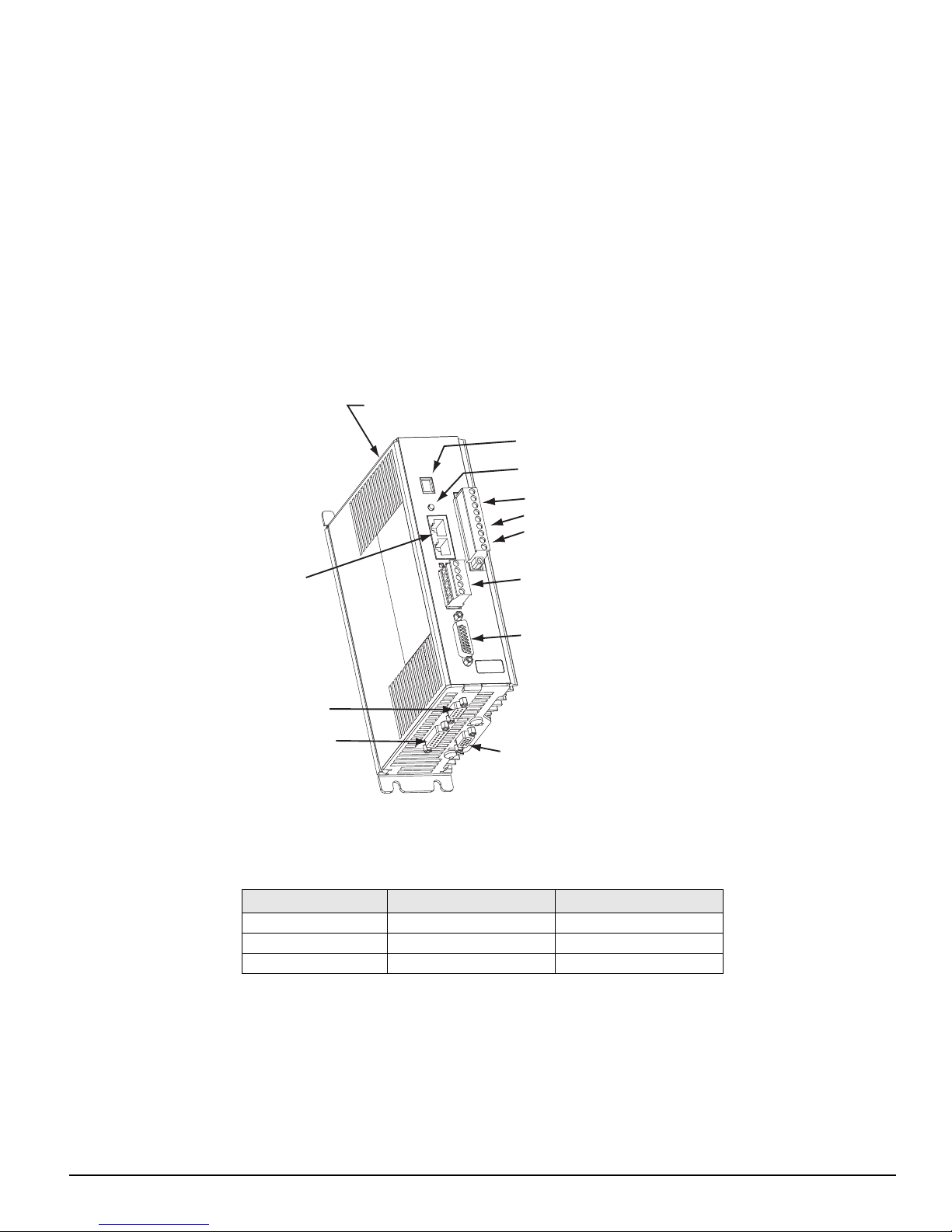
Complete diagnostics are provided for quick troubleshooting. A status/diagnostic display on the front of the drive informs the
user of the operational or fault status. The last 10 faults are stored in non-volatile memory along with a time stamp for easy
recall.
Shunt Connector (J8)
Status/Diagnostic Display
Reset Button
Reference Manual
Introduction
1
software
AC Power Connections (J1)
Motor Connections (J1)
24 Vdc Logic Power Supply Connections (J1)
Serial
Connectors (J2)
Sync Input Connector (J10)
Analog/Sync Output
Connector (J5)
EP20X-XX
DeviceNet Connector (J9)
(EP-IDN only)
Digital I/O Connctor (J3)
X00
X-X
A1
X
9606XX-X
SN 0610E014
Encoder Feedback Connector (J6)
Figure 1: Epsilon EP-IDN Drive Feature Location
Epsilon EP drives are rated at 90 Vac to 264 Vac input voltage. Epsilon EP drives are available in three current ratings.
Drive Model Continuous Current Peak Current
EP202-Ixx-EN00 2.2 A RMS 4.4 A RMS
EP204-Ixx-EN00 4 A RMS 8 A RMS
EP206-Ixx-EN00 6.5 A RMS 13 A RMS
The NT and MG motors that are matched to the Epsilon drive provide low inertia, high power to size ratios, and encoder
feedback for accurate positioning.
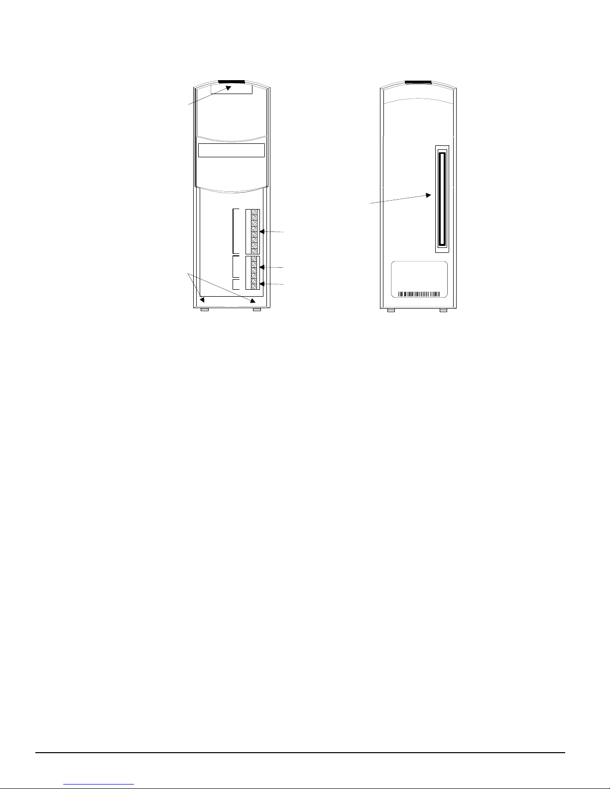
FM-2 Indexing Module
The FM-2 Module is a compact and rugged indexing module that attaches to the front of the base drive (MDS drive module).
It enables the user to initiate up to 16 different indexes, jogging and a single home routine. It also provides eight digital input
lines and four digital output lines in addition to the four input and three output lines available on the base drive. The FM-2
1.In this manual PowerTools Pro v4.0 will be referred to as PowerTools Pro.
1
Page 12
Epsilon EP-I Indexing Drive and FM-2 Indexing Module Reference Manual
Locking Latch
Aligning Tabs
100-Pin Connector
Front Back
1
2
3
4
5
6
7
8
1
2
3
4
+
-
Indexing Module
Inputs
Outputs
10-30 VDC
Inputs
Outputs
10-30 VDC
MODEL
FM-2
PART
960503-01
REV
EB/09
SER
9820B025
Module is setup using PowerTools Pro v4.0 software. PowerTools Pro v4.0 is an easy-to-use Microsoft® Windows® based
setup and diagnostics tool.
Figure 2: FM-2 Indexing Module Feature Location
2
Page 13
Epsilon EP-I Indexing Drive and FM-2 Indexing Module
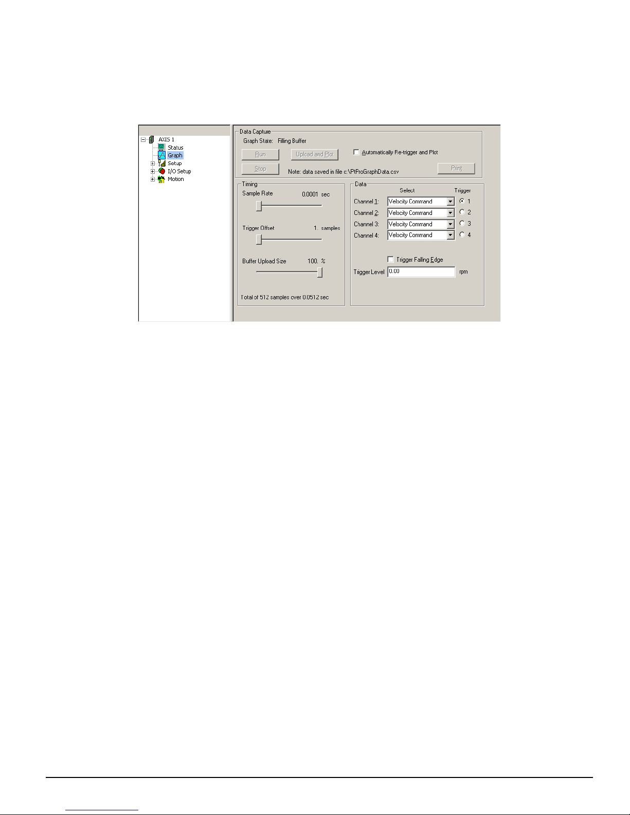
Graph View
Reference Manual
Setting Up Parameters
Figure 3: Graph View
Data Capture Group
Graph State
There are three graph state conditions in the following order: Filling Buffer, Filled. Waiting for Trigger, and Filled and
Triggered.
Run
The Run button commands the drive to begin a high speed data capture of the parameters as selected in each of the four data
channels. After the Run command button is activated the buffer will fill up to the trigger offset while the words “Filling
Buffer” appear indicating this Graph State. Once the trigger offset level is reached the words “Waiting Trigger” will appear
next to the Graph State indicating that graphical monitor is now ready to be triggered based on the trigger level selected. The
Run command button may be activated by the letter “R” on the keyboard.
Upload and Plot
The Upload and Plot button will upload captured data from the drive and display this data in the Graph window. The user
should wait for the Graph State to read “Filled and Triggered” before the data is uploaded.
Stop
The Stop button stops the data capture with the data captured at that point. You can upload and plot that data. If the buffer is
only partially filled you will get a combination of good and bad data. Stop works well as a manual trigger, in place of the
configured trigger.
Automatically Re-trigger and Plot Check Box
Select the check box and the Automatically Re-trigger and Plot tells PowerTools to monitor the graph state for the triggered
condition. When this condition occurs, it automatically initiates the UploadPlot command, waits for a brief time then initiates
the Run button to repeat the cycle. Initial the user must press the Run button to start the auto cycle.
This mechanism is only active when the graph view is displayed, If the user enters a different PowerTools view the auto
update will stop and it will restart when returning to the Graph view.
Print
The Print button is used to print the graph in the Graph window.
3
Page 14

Epsilon EP-I Indexing Drive and FM-2 Indexing Module Reference Manual
Timing Group
The sliders can be moved in several different ways.
1. With the mouse pointer over the slider, left click and hold while dragging the slider back or forth to the desire setting.
2. With the mouse pointer over the slider, left click on the slider and then the arrow keys on the PC keyboard can be used to
move the slider in fine increments. The Page Up and Page Down keys move the slider in course increments. The Home key
will move the slider all the way to the left and the End key will all the way to the right.
Sample Rate
The Sample Rate slider gives the user control of time spacing for the captured date. To give the user a better idea of what this
number means, the total number of samples and total capture time is displayed on the bottom of the “Timing” group box.
Trigger Offset
The Trigger Offset slider corresponds to the number of samples that will be included on the graph display and data capture
prior to the actual trigger. If the Trigger offset slider is completely to the left (min samples), the data capture and graphing
will start at the trigger location. If the slider is completely to the right (max samples) the graph will capture data until the
trigger point.
Buffer Upload Size
The buffer upload size slider truncates the drive captured data. If the slider is completely to the right (max) the complete buffer
will be uploaded. If the slider is completely to the left, only 1% of the buffer will be uploaded. This parameter does not effect
the data capture size, it only defines how much of the buffer will be uploaded.
Data Group
Data Channel 1 - 4 Select List Boxes
The Channel 1 through Channel 4 list boxes give the user options for parameter display. If parameters with the same units
are mapped on adjacent channels then the graphical display will show these two parameters overlapped on the same x/y axis.
If it is desirable to have two adjacent Channels with the same units mapped to separate axis on the graph then the selection
(none) should be used on the channel in between these two parameters.
Trigger Radio Buttons
Selecting the radio button will cause the graphical capture to trigger the capture off the selected Channel. The “Trigger Level”
text box on the bottom of the display will change units to the selected channel's parameter units. This trigger level may be
changed at any time but the change must be sent to the drive via the Update to RAM or Download button. If a manual trigger
is desired, set the channel to None and select the corresponding trigger radio button. If no trigger is selected the capture will
begin when the Run button is clicked and end at the end of the Sample Rate.
Module Parameter
A Module parameter text box is only available once the user has selected Module Parameter from the Select list box. This
field is used to define what parameter will be plotted on that channel. The module parameter can be entered two ways: by just
typing any module parameter using the program format for the variable, or click the Popup Variables button and the variable
window will open. Then select the variable and drag it over to the channel module parameter text box.
Trigger Mask List Box
This list box is only available when Drive Inputs, Drive Outputs, Module Inputs or Module Outputs is selected in the channel
select list box and the Trigger radio button is selected for that channel. The Trigger Mask list box will only list the inputs or
outputs for the selected channel parameter.
Trigger Falling Edge Check Box
When the Trigger Falling Edge check box is selected, the trigger is detected when the data transitions below the trigger level.
When the Trigger Falling Edge check box is clear, the trigger is detected when the data transitions above the trigger level.
Trigger Level
This is the level at which the graph is triggered. The “Trigger Level” text box will change units to the selected channel's
parameter unit. This trigger level may be changed at any time but the change must be sent to the drive via the Update to RAM
or Download button.
4
Page 15
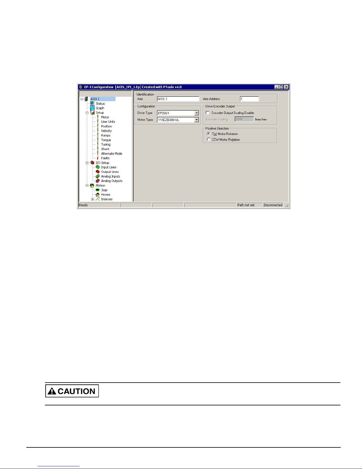
Setup View
The Setup View contains all of the primary system setup parameters. These parameters must be setup prior to using your
system.
By selecting Setup in the Hierarchy Tree, the Setup view will appear on the right side of the view (see Figure 4). The Setup
view is divided into four groups for Epsilons and five groups for FM-2 modules. The groups are Identification, Configuration,
Drive Encoder Output, Positive Direction, and Switching Frequency with an explanation of each function.
Setting Up Parameters
Figure 4: Epsilon EP-I Setup View
Identification Group
The identification group consists of the Axis and the Axis Address.
Axis
Enter a 24 character alpha/numeric name for the device you are currently setting up. Assigning a unique name for each device
in your system allows you to quickly identify a device when downloading, editing and troubleshooting. All keyboard
characters are valid.
Axis Address
Enter the “Axis Address” to which you wish to download the configuration file information. Unless you have changed the
Modbus address of your device, leave this parameter set to the default value of 1.
Configuration Group
Drive Type
Select the drive model for the application you are currently setting up.
Motor Type
Select the motor type for the application. PowerTools Pro software will display all the motor models that are available and
any user defined motors.
Selecting the wrong motor type can cause poor performance and may even damage the motor and/or drive.
5
Page 16
Epsilon EP-I Indexing Drive and FM-2 Indexing Module Reference Manual
Switching Frequency Group (FM-2 only)
Switching Frequency (FM-2 Only)
“Switching Frequency” is used to select the Drive Module switching frequency. There are two switching frequencies, 5 KHz
(default) and 10 KHz. When using 10 KHz the Drive Module current rating will be derated.
Drive Encoder Output Group
Encoder Output Scaling Check Box
Select this check box to enable the Encoder Scaling parameter of the Drive Encoder Output.
Encoder Scaling
This parameter defines the encoder resolution (lines per revolution) of the drive’s encoder output. This feature allows the user
to change the drive encoder output resolution in increments of 1 line per revolution up to the density of the encoder in the
motor. If the Encoder Output Scaling parameter is set to a value higher than the motor encoder density, the drive encoder
output density will equal that of the motor encoder. The default is to the motor encoder density.
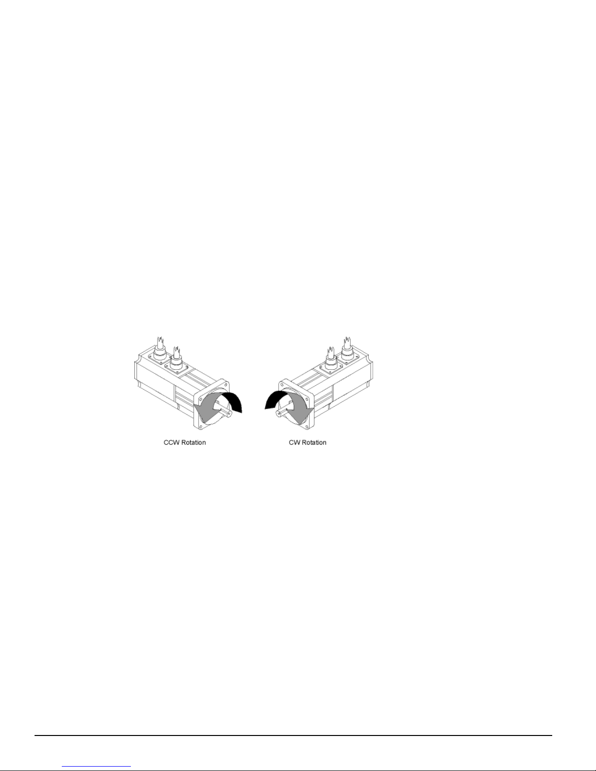
Positive Direction Group
The Positive Direction group consists of a CW (clockwise) Motor Rotation radio button and a CCW (counter-clockwise)
Motor Rotation radio button.
Positive motion will move in either a CW direction or CCW direction depending on which direction is selected. Perspective
of rotation is defined as you face the motor shaft from the front of the motor.
Figure 5: Motor Rotation Perspective
CW Motor Rotation Option Button
Select this option button for applications in which CW motor rotation is considered to be motion in the positive direction
(increasing absolute position).
CCW Motor Rotation Option Button
Select this option button for applications in which CCW motor rotation is considered to be motion in the positive direction
(increasing absolute position).
Motor View
The Motor view under Setup view is used for many different functions:
1. To see/verify the motor data for a standard motor that had been selected
2. To create a new motor entry in the .ddf file
3. To Run the Auto-Tune feature
4. To store Auto-Tune results into an existing configuration
The primary function of this view is to define the parameters for the given motor that is to be connected to the drive.
6
Page 17
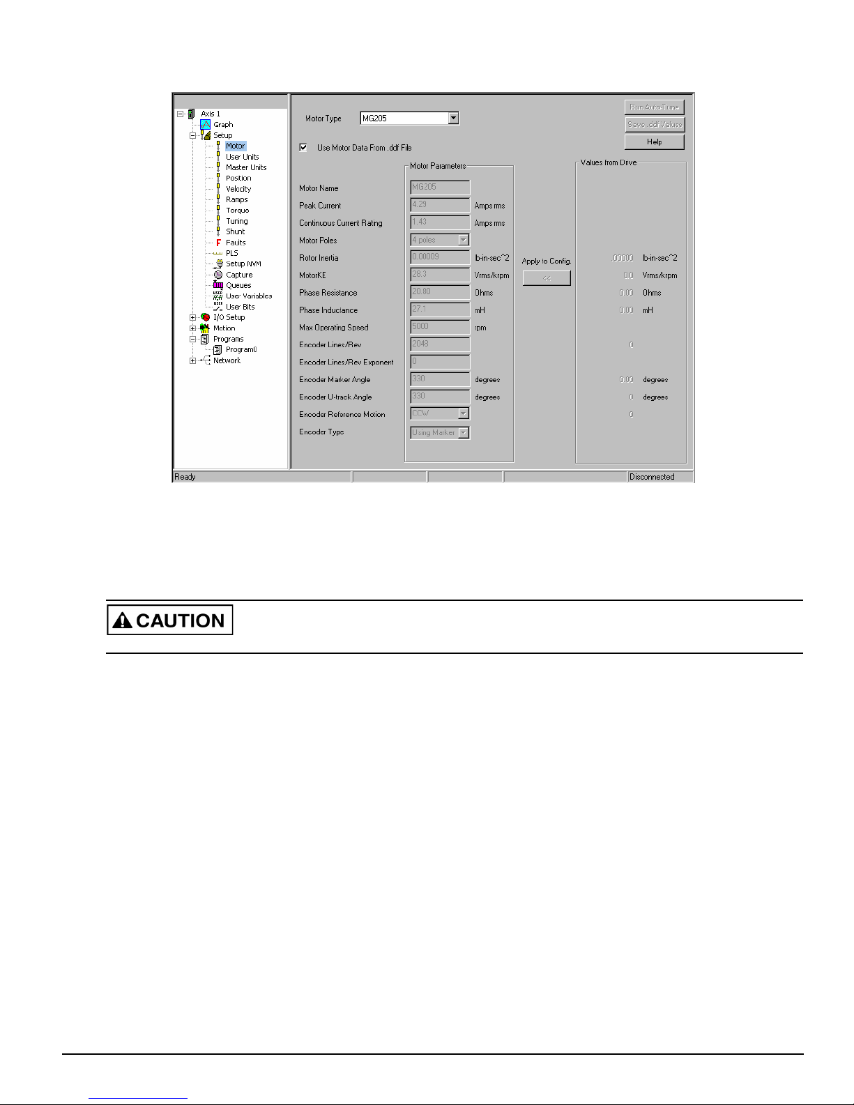
Following is a description of all the different functions on the Motor view.
Setting Up Parameters
Figure 6: Motor View
Motor Type List Box
Use this list box to select the motor type. PowerTools Pro software will display all the standard motor models and any user
defined motors.
Selecting the wrong motor type can cause instability and may cause property damage to the motor and/or drive.
Use Motor Data From .ddf File Check box
When selecting a motor for use with the Epsilon drive or a MDS/FM-2 module combination, the user has two basic options:
1. Use a motor that already exists in the standard motor definition file (StdMotor.ddf) or custom motor definition file
(Motor.ddf).
2. Create a custom motor that has not been used before.
When selecting option 1 from above (use an existing motor), the user simply selects one of the motors from the Motor Type
list at the top of the Motor view. Once the user selects a motor from the Motor Type list, the data for that motor is read from
the pertinent .ddf file and then is displayed in the Motor Parameters column on the Motor view (see Figure 6). The parameters
in this column will be dimmed and unavailable because the motor information comes directly from the .ddf file.
If the user wishes to edit one or more of the parameters read from the .ddf file, it is necessary to clear the “User Motor Data
From .ddf File” check box. Clearing the check box will break the “link” between the motor data displayed on this view, and
the motor data in the .ddf file. This is necessary because as soon as the user changes any of the values, it no longer matches
the .ddf file, and is now in effect a “custom motor”. When the “User Motor Data From .ddf File” check box is cleared, all of
the values in the Motor Parameters column will become available, and the Motor Name will be changed to “New Motor” so
that there is no association with the existing motor that was previously selected. The user can now change any of the values
as desired and give the motor a new name. Once the values have been changed, the motor data only exists within the active
configuration. To save the new values into the .ddf file, the user must click on the Save .ddf Values button on the right side
of the view.
7
Page 18

Epsilon EP-I Indexing Drive and FM-2 Indexing Module Reference Manual
Motor Parameters Column
Motor Parameters column is a column of data displayed on the Motor view under the Setup view (See Figure 6). This column
of data contains the values for each of the motor data parameters. The values in this column are unavailable for edit if the
“Use Motor Data From .ddf File” check box is selected. This means that since the data is associated with the .ddf file, it cannot
be changed. The values in this column become available when the “Use Motor Data From .ddf File” check box is cleared.
The user can then change one or more of the parameter values because there no longer is a link to the data in the .ddf file.
If the user does edit motor parameter values on this view, those values are only stored within that particular configuration file.
In order to save the values to the .ddf file, the user must click the “Save .ddf Values” button on the right side of the view.
Below are the motor parameter with a brief description.
Motor Name
The motor name is limited to 12 characters and must begin with an alpha character (non-numeric character). This is the motor
name that will appear in the “Motor Type” list box above.
Peak Current
Specifies the peak current allowed by the motor. The motor manufacturer typically provides the peak current data.
If a system is “drive limited” (meaning that the motor can handle more current than the drive can deliver), the peak current
actually used by the system may be lower than the value specified here.
Continuous Current Rating
Specifies the continuous current allowed by the motor. It is used to determine the drive continuous current and peak current
limits. The drive can also limit the continuous current to the motor based on the drive capacity. The motor manufacturer
typically provides the continuous current data.
If a system is “drive limited” (meaning that the motor can handle more current than the drive can deliver), the continuous
current actually used by the system may be lower than the value specified here.
Motor Poles
Specifies the number of magnetic pole pairs (N-S) on the motor. The supported values are 2, 4, 6, 8, 10, 12, 14 and 16 poles.
The motor manufacturer typically provides the motor pole information.
Rotor Inertia
This parameter specifies the inertia of the motor rotor. The drive uses this parameter to interpret the “Inertia Ratio” parameter.
“Inertia Ratio” is specified as a ratio of reflected load inertia to motor inertia.
Motor KE
Specifies the Ke of the motor. The units are Vrms/ kRPM. The line-to-line voltage will have this RMS value when the motor
is rotated at 1000 RPM. The range is 5.0 to 500.0 Vrms/ kRPM. The motor manufacturer will typically provide the Ke data.
Phase Resistance
Specifies the phase-to-phase resistance of the motor. This value is determined by measuring the resistance between any two
motor stator terminals with an ohm meter. The range is.1 to 50 ohms.
Phase Inductance
Specifies the phase-to-phase inductance of the motor.
Max Operating Speed
This parameter specifies the maximum speed of the motor when used with a variable speed drive to achieve velocities over
the rated base speed of the motor.
Encoder Lines/Rev
Specifies a coefficient for determining the number of encoder lines per mechanical revolution. The supported values are 1 to
16383. The equation for determining the total number of encoder lines per revolutions is:
nLines = n*10x
where:
8
Page 19

Setting Up Parameters
nLines = Total number of Encoder Lines
n = Motor Encoder Lines per Rev Coefficient
x = Motor Encoder Exponent
The total number of encoder lines is used both for commutation and for position/velocity control. To properly commutate the
motor, the drive must know the electrical angle (the angle between the motor magnetic field and stator coils).
Encoder Lines/Rev Exponent
Specifies a coefficient for determining the number of encoder lines per mechanical revolution. The supported values are 1 to
16383. The equation for determining the total number of encoder lines per revolutions is:
nLines = n*10x
where:
nLines = Total number of Encoder Lines
n = Motor Encoder Lines per Rev Coefficient
x = Motor Encoder Exponent
The total number of encoder lines is used both for commutation and for position/velocity control. To properly commutate the
motor, the drive must know the electrical angle (the angle between the motor magnetic field and stator coils).
Encoder Marker Angle
Specifies the electrical angle at which the marker (Z) pulse occurs with reference to VTS when the motor is spun in the encoder
reference direction. At power-up the drive obtains an initial estimate of the electrical angle from the status of the U, V and W
commutation tracks. This estimate can be off by as much as 30 °.
When the drive receives the marker pulse, the drive will, within one second, gradually shift the commutation to the more
accurate electrical angle specified by this parameter. The system will then operate more efficiently.
Encoder U-track Angle
Specifies the electrical angle at which the rising edge of the U commutation track will occur with reference to VTS when the
motor is spun in the encoder reference direction.
At power-up the drive looks at the status of the U, V and W commutation tracks and, using this parameter, obtains a crude (±
30 °) estimate of the electrical angle.
Encoder Reference Motion
Specifies the direction of motion assumed in phase plots of the encoder’s quadrature and summation signals. The supported
values are CW(1) and CCW(0). Your encoder may have the same phase plot but is generated from a different direction of
rotation. This parameter affects the way the drive interprets the quadrature and commutation signals.
Encoder Type
The supported values for this parameter are 1 and 0. If set to a 1 the drive uses the Encoder Marker angle as well as the
Encoder U Angle for commutation. If this parameter is set to a 0, the drive uses only the Encoder U Angle.
Values from Drive Column
The Values from Drive column is a group of parameters that are constantly being read from the drive. The theory of operation
is that the user will often perform an Auto-Tune function that reads/measures/calculates data. The results of those
measurements are read from the drive and displayed in the Values from Drive column. Once they are displayed in PowerTools
Pro (in the Values From Drive column) the user can apply those values to the Motor Parameters column by clicking on the
Apply to Config. button, in the middle of the Motor view (this button looks like a series of arrows pointing from the Values
from Drive column towards the Motor Parameters column).
The values in the Values from Drive column are not saved as part of the configuration file. To save these values, the user
must use the “Apply to Config” button to save them.
This column is only functional when online with the device. When offline, the values in the Values from Drive column will
all read zero.
Apply to Config. Button
When the user runs the Auto-Tune feature PowerTools Pro reads the results of the Auto-Tune and displays them in the Values
from Drive column of the Motor view. After the Auto-Tune, the measured values are only saved in the Drive NVM, and not
9
Page 20

Epsilon EP-I Indexing Drive and FM-2 Indexing Module Reference Manual
in the FM3/4 module. Therefore, in order to store the values in the FM module, the Auto-Tune values must be applied to the
configuration file. When the user presses “Apply to Config.”, the values in the “Values From Drive” column are transferred
into the Motor Parameters column. Then the values must be downloaded by downloading the entire configuration file using
Device > Download.
Run Auto-Tune Button
The drive has the ability to run an Auto-Tune operation thereby measuring several different motor parameters. Doing so
allows the drive to obtain certain parameters that are not typically provided by the motor manufacturer, and also optimizes
other drive parameters to work properly with the connected motor/load.
PowerTools Pro allows the user to initiate the Auto-Tune feature from the Motor view.
The following table shows which parameters must be entered in order to run the Auto-Tune feature, and which parameters
are measured by the Auto-Tune.
Motor Parameters Needed to Run Auto-Tune Measured by Auto-Tune Mode #
Motor Name
Peak Current •
Continuous Current Rating •
Motor Poles •
Rotor Inertia 3
Motor Ke 3
Phase Resistance 2,3
Phase Inductance 2,3
Max Operation Speed •
Encoder Lines/Rev • 1,2,3
Encoder Lines/Rev Exponent • 1,2,3
Encoder Marker Angle 1,2,3
Encoder U-Marker 1,2,3
Encoder Reference Motion 1,2,3
Encoder Type
Some Auto-Tunes cause motion while others do not. It is important to read and understand the warnings and instructions on
the Auto-Tune windows. It is strongly recommended to unload the motor if Auto-Tune Mode #3 is commanded.
When online with the drive, to initiate an Auto-Tune, click RunAuto-Tune button. The Auto-Tune dialog box opens and
contains warnings and instructions related to the Auto-Tune procedure, as well as selection of the Auto-Tune mode. An
example of one of the Auto-Tune windows is shown in Figure 7.
10
Page 21
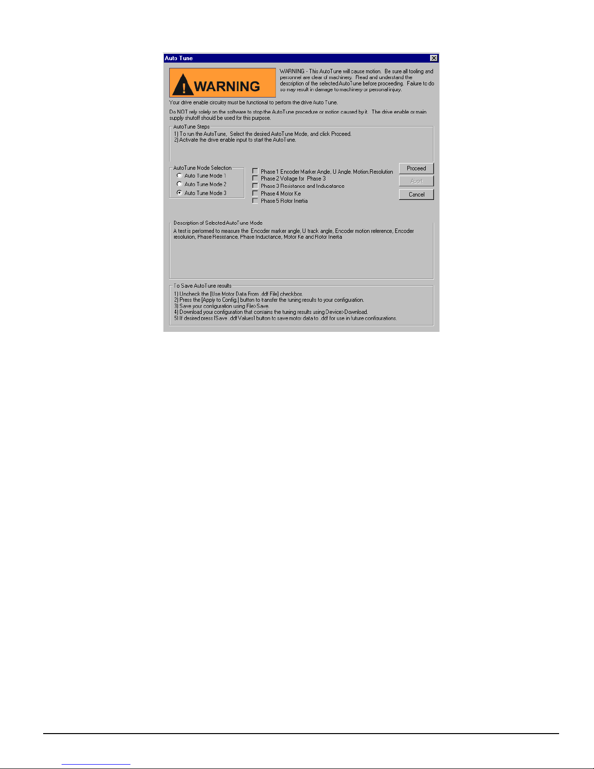
Setting Up Parameters
Figure 7: Auto-Tune Dialog Box - Auto-Tune Mode 3
After the Auto-Tune Mode has been selected, click Proceed, to start the Auto-Tune. When the Auto-Tune is completed the
results will be in the Values from Drive column on the Motor view.
Save .ddf Values Button
Once the user has entered the data for the motor they are using, they may or may not wish to save the motor data to the
Motor.ddf file so it can be easily recalled at a later time. If the user does not save the motor data to the Motor.ddf file, then
the motor data will only reside in the specific application configuration file that it has been entered into.
In order to save the motor data to the Motor.ddf file, click the Save .ddf Values button. This takes all the parameter values
and writes them to the Motor.ddf file.
When saving to the .ddf file, if PowerTools Pro finds that a motor already exists with the same name, the User Defined Motor
Name Conflict dialog box will appear. The user must then decide how to proceed with saving the motor data .ddf file.
User Defined Motor Name Conflict Dialog Box
The purpose of this dialog box is to resolve conflicts between the application’s motor settings and those defined in the .ddf
file.
The User Defined Motor Name Conflict dialog box opens during the following conditions:
1. From the Motor view, click the Save .ddf values button and the motor already exists with the same name but has different
motor parameters
2. Opening an application (or uploading a application), where the Use Motor data from the .ddf file check box is select but
the data in the application no longer matches the .ddf file.
This occasionally occurs when a newer version of PowerTools Pro is installed and the parameters for the standard motors
has been updated in the .ddf file.
If the motor name does not exist in the .ddf file, it will be written into the file.
11
Page 22
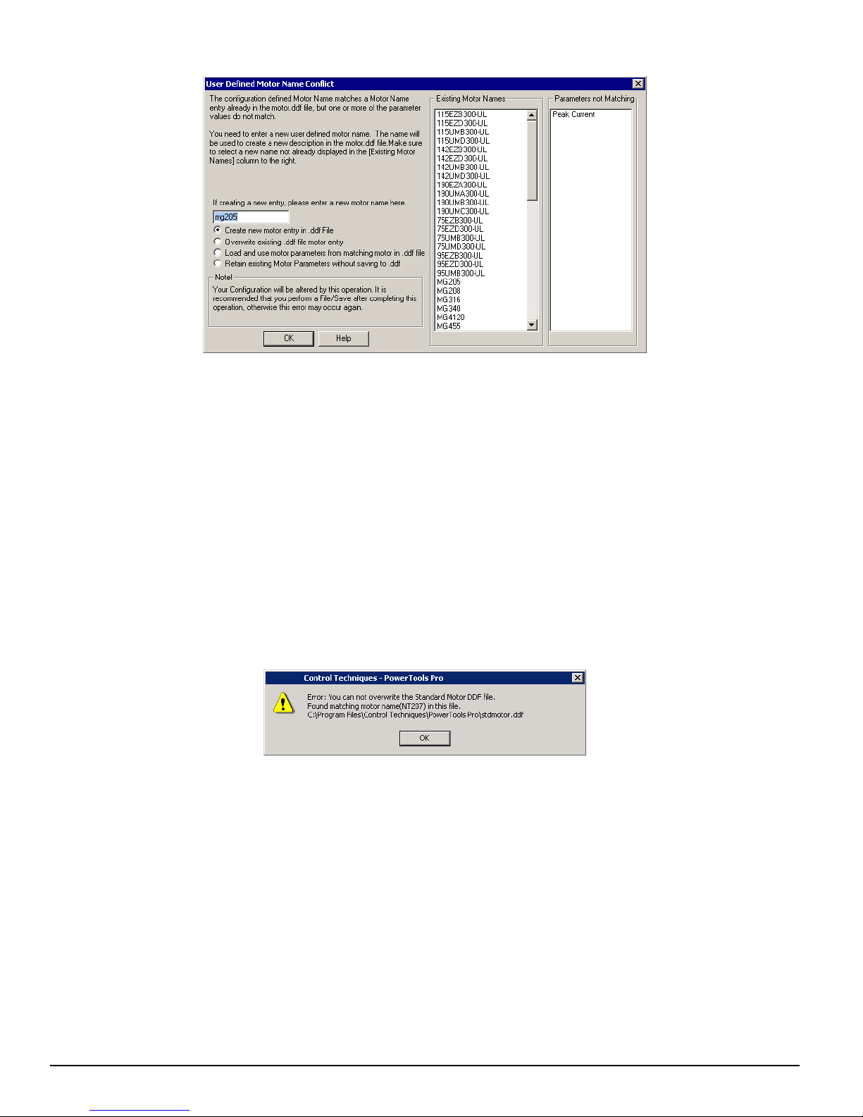
Epsilon EP-I Indexing Drive and FM-2 Indexing Module Reference Manual
Figure 8: The User Defined Motor Name Conflict Dialog Box
The User Defined Motor Name Conflict dialog box presents the user with four options on how to proceed with saving the
motor data. Those four options are:
Create new motor entry In .ddf File
The user can select to keep the existing data and create a new entry into the motor.ddf file with a different name. After
selecting this option, the user simply enters a new name in the Please enter a new motor name text box. Then click OK, the
data will be written to the .ddf file using the new motor name.
Overwrite existing .ddf file motor entry
The user can select to overwrite the existing data in the .ddf file with the current data in the Motor Parameters column. If this
option is selected, the data in the .ddf file will be overwritten and the overwritten data will be lost forever. The overwritten
data cannot be recovered.
If the user attempts to overwrite data for a Standard Motor (in the stdmotor.ddf file), the operation will be canceled and the
user will be notified that they cannot proceed. The figure below shows the error message that will be produced when the user
attempts to overwrite a standard motor. In this case, the user would need to change the motor name before saving to the .ddf
file.
Load and use motor parameters from matching motor in .ddf file
If this option is selected, the motor data in the Motor.ddf or stdmotor.ddf file for the matching Motor Name will overwrite
the data in the Motor Parameters column. After this option is selected, the “Use Motor Data From .ddf File” check box will
be selected, and all the parameter values will be unavailable.
Retain existing Motor Parameters without saving to .ddf
If the user selects this option, the values in the Motor Parameters column will not be written to the motor.ddf file, and the
values will only reside within the configuration file. The specific motor data values will not be available for selection in the
Motor Type list box because they are not saved to the .ddf file. The “Save .ddf Values” operation is in effect canceled.
Existing Motor Names List Box
This list box is part of the User Defined Motor Name Conflict dialog box and contains all the names of the motors that exist
in the motor.ddf and stdmotor.ddf files. When selecting a new name, it is important to select a name that is not already
displayed in this list box.
12
Page 23

Parameters Not Matching List
This list is part of the User Defined Motor Name Conflict dialog box and displays the parameter value(s) from the Motor
Parameters column that do not match the equivalent parameter value in either the motor.ddf or stdmotor.ddf files, for the
motor with the matching name.
This helps the user to determine whether they wish to overwrite, cancel, or create a new motor with this Save .ddf Values
operation.
User Units View
The User Units View is used to scale the desired application units into known values. All information for distance, velocity,
and accel/decel units are set up here and used throughout the system setup.
By selecting User Units in the Hierarchy Tree, the User Units View will appear on the right (see Figure 9).
Setting Up Parameters
Figure 9: User Units View
Distance Group
Units Name
Select the type of units to be used throughout the configuration for all Position/Distance parameters. The default units are
revs.
Decimal Places
This will specify the number of digits after the decimal place to be used in all distance/position parameters for the entire
configuration.
Distance Scaling
This will specify the number of user units in 1.0000 motor revolution. This parameter also determines the resolution of
distance/position parameters for the entire configuration. The number of decimal places specified here sets the maximum
resolution.
For Example: If the user has a leadscrew with a 0.5" lead and wishes to perform indexes of 0.025", the Units Scaling must be
set to 0.500. By specifying three digits after the decimal place, the user will be able to enter the three digits necessary for the
index distance.
Velocity Group
Decimal Places
This will specify the number of digits after the decimal place to be used in all Velocity parameters.
13
Page 24
Epsilon EP-I Indexing Drive and FM-2 Indexing Module Reference Manual
Time Scale Group
Time Base
Select either minute or second as the time scale for the configuration. The default time scale is minutes. If the selected time
scale is seconds, then the velocity units will appear as
user units/sec. If the selected time scale is minutes, the velocity units will appear as
user units/minute.
If the selected time scale is seconds, then the accel/decel units will appear as user units/sec
minutes, the accel/decel units will appear as
msec/(1000 (user units)/min) or msec/(k (user units)/min). Therefore, for accel/decel units, the default is msec/kRPM (the
same as previous versions of the FM-2 module).
Acceleration Group
Decimal Places
This will specify the number of digits after the decimal place to be used in all Acceleration/Deceleration parameters.
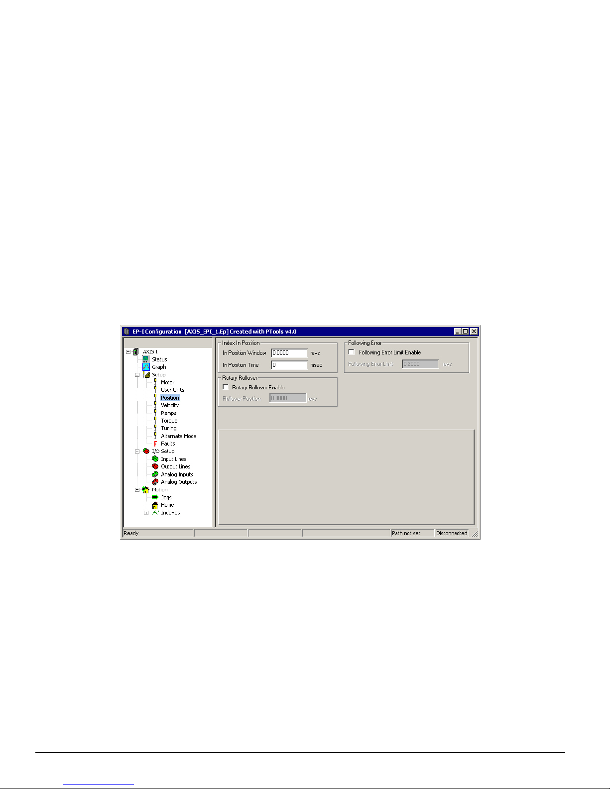
Position View
The Position View allows you to set up and view the parameters related to drive positioning. In, Position has been selected
in the Hierarchy Tree. The right side of the view is divided into groups. An explanation of the groups and their functions is
provided below.
2
. If the selected time scale is
Figure 10: Position View
Index In Position Group
In Position
The In Position (InPosn) source will activate at the end of a move if the absolute value of following error is less than or equal
to the In Position Window for the In Position Time.
In Position Window
The absolute value of the Following Error must be less than or equal to this value at the end of an index in order for the InPosn
source to activate. This window is set in units specified in the User Units View.
For example:
The In Position window is set to 0.0025 revs. At the end of an index, the following error is calculated to be 0.0012
revolutions. Therefore, the InPosn output will activate.
14
Page 25

Or the In Position window is set to 0.001 inches. If at the end of an index, the following error is calculated to be 0.0015
inches, then the InPosn output will not activate.
In Position Time
This is the amount of time in seconds that commanded motion must be complete and the absolute value of the following error
must be less than the In Position Window parameter for the InPosn output to activate. If set to zero (default), then the InPosn
output will activate as soon as motion stops and the following error is less than the In Position Window parameter.
Following Error Group
Following Error Limit Enable Check Box
Select this check box to enable (or clear this check box to disable) the Following Error Limit. If enabled, a fault will be
generated if the absolute value of the following error ever exceeds the value in the following error parameter. If disabled, a
fault will never be generated.
Following Error Limit
Following Error is the difference between the Position Command and the Position Feedback. It is positive when the Position
Command is greater than the Position Feedback. If the absolute value of the following error exceeds the value entered here,
the drive will generate a Following Error Fault (F). All accumulated Following Error will be cleared when the drive is
disabled.
The Following Error Limit is defined in user units.
Setting Up Parameters
Rotary Group
Rotary Rollover Enable Check Box
Select this check box to enable (or disable if check box is clear) the rotary rollover feature.
Rollover Position
This parameter is used in rotary applications and determines the position at which the internal position counter will be reset
to zero.
Example:
The user has a rotary table application with distance user units of degrees, 360.00 degrees/1 rev. The Rotary Rollover would
be set to a value of 360°.
The motor is traveling in the positive direction. As the feedback position reaches 359.999 and continues on, the feedback
position will reset (or roll-over) to zero. If the motor changes direction and travels in the negative direction, the position will
rollover at 0 to 359.999 degrees and count down. The resolution of the rotary rollover point is determined by the Distance
Units Decimal Places parameter on the User Units view in the PowerTools Pro software.
If an absolute index is used with a non-zero rotary rollover point, the FM-3/4 module will calculate the shortest path to its
destination and move in the required direction.
To force the motor to run a certain direction, use the Rotary Plus or Rotary Minus type of indexes.
Online Tab
While online with the device, the lower half of the view is the Online tab and the following real-time data will be displayed.
Motor Position Group
Position Command
This is the commanded position in user units generated by the device. This is set to zero when the Absolute Position Valid
output function is activated. The Position Command is specified in user units.
Position Feedback
This is the feedback position of the motor. It is set to zero when the Absolute Position Valid output function is activated.
Position Feedback is specified in user units.
15
Page 26

Epsilon EP-I Indexing Drive and FM-2 Indexing Module Reference Manual
Following Error
The Following Error is the difference (in user units) between the Position Command and the Position Feedback. It is positive
when the Position Command is greater than the Position Feedback.
Encoder Position
The motor position in encoder counts since power up when the value was set to zero. This is a signed 32 bit value. This is set
to zero when the Absolute Position Valid output function is activated.
Pulse Input Posn
This parameter returns the total number of actual pulses received on the pulse input hardware. This value is active in all
operating modes.
16
Page 27
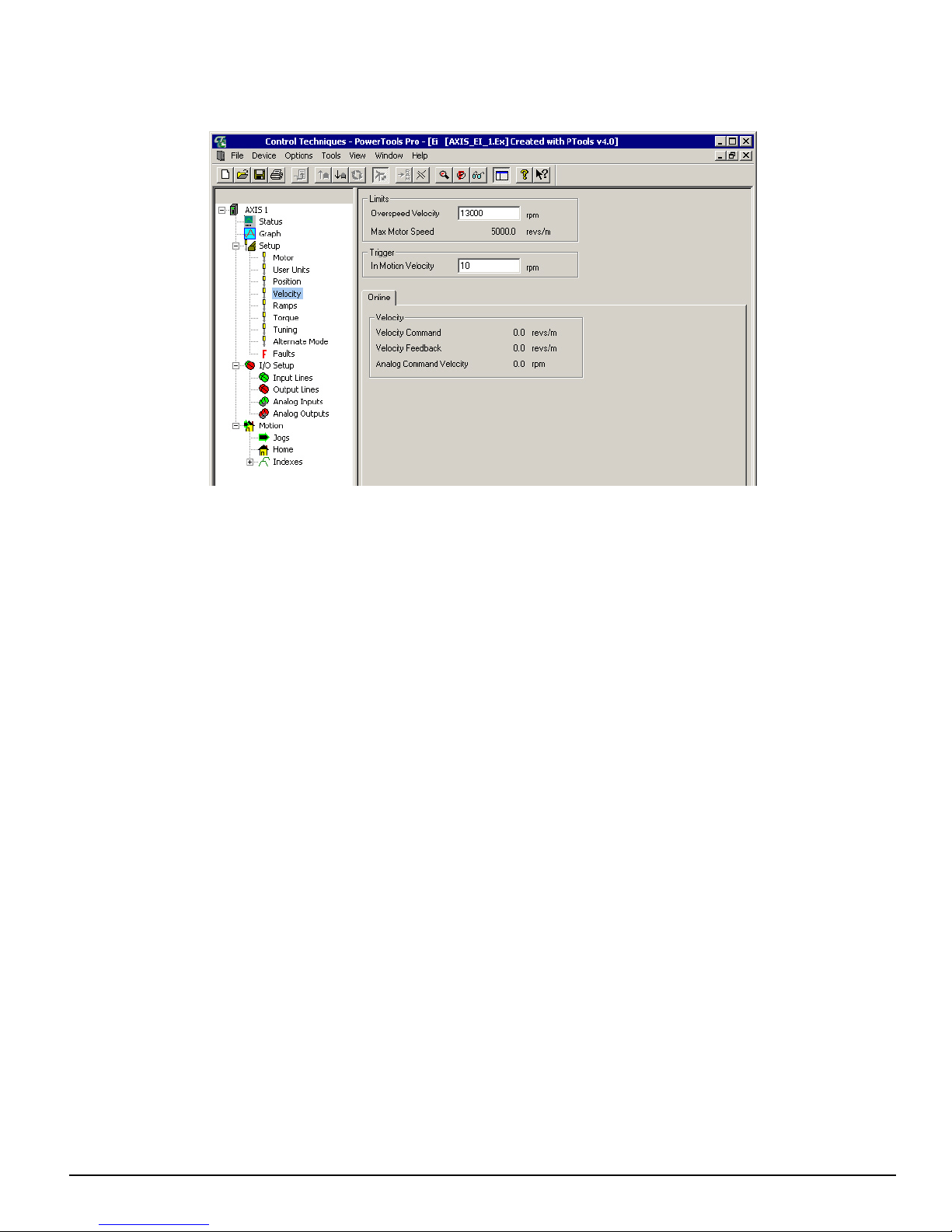
Velocity View
This view allows the user to set the drive limits, and if online, view the velocity feedback parameters.
Setting Up Parameters
Figure 11: Velocity View - Online
Limits Group
Overspeed Velocity
This parameter specifies the maximum allowable speed. If the Velocity Feedback exceeds either the drive’s internal
overspeed fault limit or the value of the Overspeed Velocity, an Overspeed Fault will be generated. The internal overspeed
fault limit is equal to 150 percent of the Motor Maximum Operating Speed.
Trigger Group
In Motion Velocity
This parameter sets the activation point for both the In + Motion and In - Motion output functions. The output function will
deactivate when the motor velocity slows to half of this value.
Online Tab
Velocity Group
All parameters in this group are only available when online with the device.
Velocity Command
The Velocity Command is the actual command received by the velocity loop.
Velocity Feedback
This parameter is the actual feedback motor velocity.
Analog Command Velocity
The drive is in Analog Velocity mode this parameter gives the current velocity commanded due to the Analog input function.
17
Page 28
Epsilon EP-I Indexing Drive and FM-2 Indexing Module Reference Manual
Note
Ramps View
Ramps Group
Stop Deceleration
The value you enter here defines the rate of velocity change to zero speed when a Stop input function is activated.
Travel Limit Deceleration
The value you enter here defines the rate of velocity change to zero speed when a Travel Limit input function is activated.
Limits Group
Analog Accel/Decel Limit
This feature allows you to limit the accel and decel rate when using the analog input for velocity control. This makes it very
simple to use the drive in high performance, variable speed, start-stop applications such as Clutch-Brake replacements
without requiring a sophisticated controller to control the acceleration ramps. In applications which do not require the drive
to limit the ramps such as when using an external position controller, the parameter can be set to “0” (its default value). If the
Analog Accel/Decel Limit parameter value is changed during a ramp, the new ramp limit is imposed within the next servo
loop update.
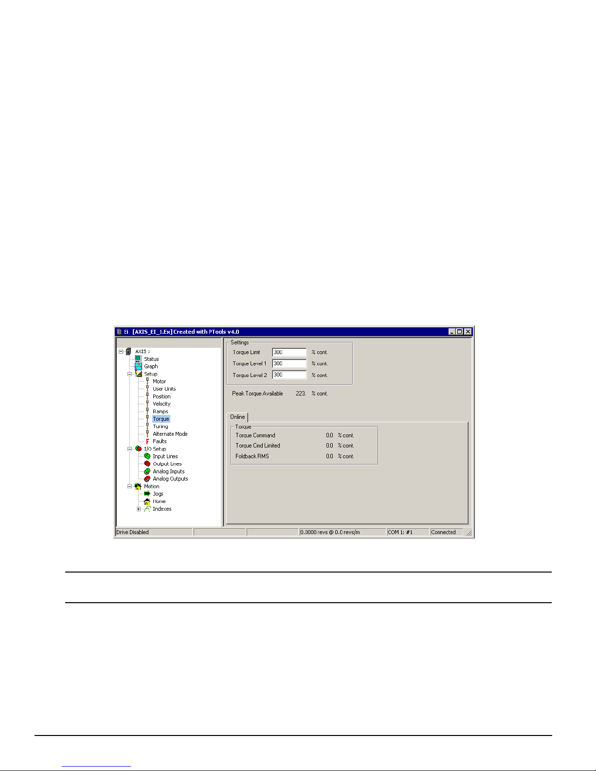
Torque View
This view allows the user to edit the Torque Limit and when online with the device view the torque parameters.
Figure 12: Torque View - Online
The Torque Limit value takes effect only when the Torque Limit Enable input function is active.
These parameters are continuously updated while online with the drive.
Settings Group
Torque Limit
This value is the level which the Torque Command will be limited to when the Torque Limit Enable input function is active.
To make the Torque Limit always active, set the Torque Limit Enable Input function to be Always Active.
18
Page 29

Torque Level 1 and 2
This parameter sets the activation level for the Torque Level 1 Active and Torque Level 2 Active output functions.
Peak Torque Available
This displays the maximum torque available from the selected drive and motor combination. This is calculated by
PowerTools Pro and is not a drive parameter.
Online Tab
Torque Group
Torque Command
The torque available from the particular drive and motor combination.
This parameter returns the torque command value before it is limited. The torque command may be limited by either the
Torque Limit (if the Torque Limit Enable input function is active) or Current Foldback.
Torque Cmd Limited
This displays the percent of torque being commanded to the motor. This value is the result of the Torque Command after
being limited by the current foldback and the Torque Limit value (if active).
Foldback RMS
Setting Up Parameters
This parameter accurately models the thermal heating and cooling of the drive and motor. When it reaches 100 percent,
current foldback will be activated.
19
Page 30
Epsilon EP-I Indexing Drive and FM-2 Indexing Module Reference Manual
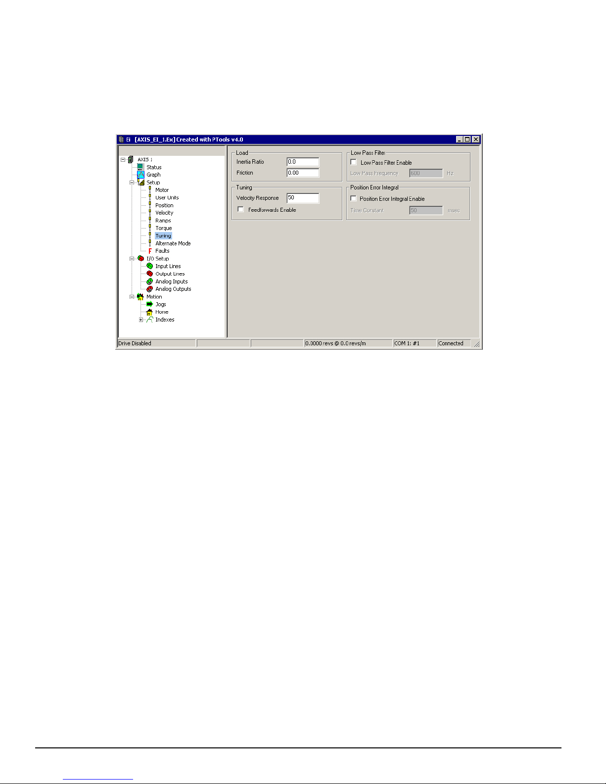
Tuning View
All parameters on the Tuning view are related to the load on the motor and application requirements.
The load on the motor is specified by two parameters: Inertia Ratio and Friction. Typical application requirements are
specified by the response adjustment and Feedforward Gains. Position Error Integral is provided to compensate for systems
with high friction or vertical loads. Low Pass Filter is provided to filter machine resonance that are present in some
applications.
Figure 13: Tuning View
Load Group
Inertia Ratio
Inertia Ratio specifies the load to motor inertia ratio and has a range of 0.0 to 50.0. If the exact inertia is unknown, a
conservative approximate value should be used. If you enter an inertia value higher than the actual inertia, the resultant motor
response will tend to be more oscillatory.
Friction
This parameter is characterized in terms of the rate of friction increase per 100 motor RPM. If estimated, always use a
conservative (less than or equal to actual) estimate. If the friction is completely unknown, a value of zero should be used. A
typical value used here is less than one percent.
Tuning Group
Velocity Response
The Velocity Response parameter adjusts the velocity loop bandwidth with a range of 1 to 500 Hertz. In general, it affects
how quickly the drive will respond to commands, load disturbances and velocity corrections. A good value to start with (the
default) is 50 Hz. The maximum value recommended is 80 Hz.
Feedforwards Enable Check Box
When this check box is selected feedforwards are enabled, the accuracy of the Inertia and Friction parameters is very
important. If the Inertia parameter is larger than the actual inertia, the result could be a significant overshoot during ramping.
If the Inertia parameter is smaller than the actual inertia, following error during ramping will be reduced but not eliminated.
If the Friction parameter is greater than the actual friction, it may result in velocity error or instability. If the Friction
parameter is less than the actual friction, velocity error will be reduced but not eliminated.
20
Page 31

Low Pass Filter Group
Low Pass Filter Enable Check Box
This check box when selected enables a low pass filter applied to the output of the velocity command before the torque
compensator. The low pass filter is only active in Pulse and Velocity modes, not Torque Modes.
Low Pass Frequency
This parameter defines the low pass filter cut-off frequency. Signals exceeding this frequency will be filtered at a rate of 40
dB per decade.
Position Error Integral Group
Position Error Integral Enable Check Box
When selected this enables the Time Constant parameter.
Time Constant
Position Error Integral is a control term which can be used to compensate for the continuous torque required to hold a vertical
load against gravity. It is also useful in low speed applications which have high friction.
It also helps maintain accurate command execution during steady state or low frequency torque disturbances (typically less
than 10 Hz) or when holding a non-counterbalanced vertical load in position.
The adjustment parameter is Position Error Integral Time Constant which is available in the Tuning View of PowerTools Pro.
This parameter determines how quickly the drive will attempt to eliminate the following error. The time constant is in
milliseconds and defines how long it will take to decrease the following error by 63%. (3 time constants will reduce the
following error by 96%). The range for this parameter is 5 to 500 milliseconds. In certain circumstances the value actually
used by the drive will be greater than the value specified in PowerTools Pro because the minimum allowed time constant
value is a function of the ‘Response’ parameter. The formula is Min. Time Constant = 1000/Response.
Setting Up Parameters
For example, with ‘Response’ set to 50, the minimum time constant value is 1000/50 = 20 msec. A higher time constant value
will minimize instability with more compliant loads such as long drive shafts, or spring loads. A lower time constant setting
will increase the response and will stiffen the system.
21
Page 32

Epsilon EP-I Indexing Drive and FM-2 Indexing Module Reference Manual
Alternate Mode View
Figure 14: Alternate View
Alternate Mode Selection
See “Alternate Mode Select” on page 70 for details on selecting a mode of operation.
22
Page 33

Faults View
Setting Up Parameters
Figure 15: Faults View - Online
Fault Enable Group
Low DC Bus Fault Enable
This parameter’s default setting is enabled. When enabled, the drive will detect a low DC bus at 60 Vdc and will log a Low
DC Bus Fault if a power down is not completed after the low DC bus is detected. Clearing this check box will disable the
Low DC Bus Voltage Fault. This will allow the drive to operate at a DC bus voltage below 60 Vdc as long as the logic power
is supplied by the Alternate Power Supply (APS) with an Epsilon classic drive and a Logic Power Supply with the Epsilon
EP-I drive.
Encoder State Fault Enable
This parameter’s default setting is enabled. When enabled, the drive will detect encoder state faults. Refer to Fault Codes in
the Diagnostic and Troubleshooting section of this manual. The drive will not detect Encoder State faults when the fault is
disabled. Disabling encoder faults is necessary for some types of programmable encoders when the state transitions are not
always deterministic.
Commutation Hardware Fault Enable
When this checkbox is selected, faults occurring from the commutation tracks U, V, and W will be recognized as "E" faults
in the drive. When this checkbox is clear, no fault will occur due to the commutation tracks. This functionality can be useful
to diagnose the nature of the "E" fault. If the checkbox is clear and "E" faults are still occurring, then the encoder lines (A,
A/, B, B/, Z, Z/) are the most likely source of the "E" fault.
23
Page 34

Epsilon EP-I Indexing Drive and FM-2 Indexing Module Reference Manual
I/O Setup
Input Lines View
The Input Lines view is used to assign an input function to an input line. This view is divided into two windows. The “Input
Function” window, on the left side, displays the input functions available and the function configuration. The “Input Line”
window, on the right side, displays the input lines, attached input functions and the debounce value.
To assign an input function, position the mouse pointer over the function on the left to assign it to the line on the right. Press
the left mouse button while over the function, and hold the button down. While holding the left button down, drag the function
until the pointer is positioned over the desired line and release the left mouse button.
To unassign an input function, position the pointer over the function on the left. Press the left mouse button while over the
function, and hold the button down. While holding the left button down, drag the function over to the right and release the
left mouse button.
Figure 16: Inputs View
Input Function Window
This window allows the user to select an input function and assign it to an input line. When online with the device there will
be a virtual LED to the left of the input function name that shows the state of the input function.
Configuration
The configuration of each input function is displayed next to the input function when the active state is changed from default.
The default configuration is Active On.
Active Off Check Box
This check box allows you to change the “Active On/Off” state. Select the desired input function in the input function
window, then select or clear the “Active Off” check box.
Making an input function “Active On” means that it will be active when 10 Vdc to 30 Vdc is applied to the input line it’s
assigned to and is inactive when no voltage is applied to the line. Making an input function "Active Off" means that it will
be active when no voltage is applied to the input line and inactive while 10 Vdc to 30 Vdc is being applied.
Always Active Check Box
This check box is used to make an input function “Always Active”. When you make an input function always active, it’s
active whether assigned to an input line or not. If you make an input function “Always Active” then assign it to an input line,
that function will be active whether or not voltage is applied to the assigned line.
24
Page 35

Setting Up Parameters
Input
Terminal
Input Lines
Force On/Off
Command
Input Lines
Force On/Off
Enable
Debounce
Timer
Input Line
Debounced
Status
Input Line
Status
Input Line
Raw Status
Input Line Window
This window displays the input function assigned to the input line and the configuration of the input line and input function.
Attached Function
This displays the Input Function assigned each particular Input Line.
Configuration
The debounce value is displayed next to each input line, the active state for the attached input function is shown next to the
input function.
Debounce Text box
The debounce value is displayed next to each input line. This feature helps prevent false input triggering in noisy electrical
environments. Enter a “Debounce Time” in milliseconds. The value entered here is the minimum amount of time the input
line will need to be active before it is recognized as a valid input.
Figure 17: Input Line Diagram
25
Page 36

Epsilon EP-I Indexing Drive and FM-2 Indexing Module Reference Manual
Note
Outputs View
This view is divided into two windows. The “Output Function” window, on the left side, displays the available output
functions. The “Output Line” window, on the right side, displays the output lines, the attached output function and the line
configuration (Active Off).
Figure 18: Outputs View for a Epsilon EP-I Drive
For wiring information, refer to the “Installation” section of the Epsilon EP Installation Manual (P/N 400518-01), or the
Modular Drive System Reference Manual (P/N 400525-01).
Output Function Window
This window allows selection of the output function to be assigned to an output line.
To assign an output function, position the mouse pointer over the function on the left to assign it to the line on the right. Press
the left mouse button while over the function, and hold the button down. While holding the left button down, drag the function
until the pointer is positioned over the desired line and release the left mouse button.
To unassign an output function, position the pointer over the function on the left. Press the left mouse button while over the
function, and hold the button down. While holding the left button down, drag the function over to the right and release the
left mouse button.
Output Lines Window
Attached Function
This feature displays the Output Function assigned to each particular Output Line.
Configuration
The configuration of each output line is displayed nest to the output line when the active state is changed from default. The
default configuration is Active On, see Active Off check box below.
26
Page 37

Active Off Check Box
The default active state of an output line is Active On. This means that the output line will supply a voltage when the result
of the logical Or of the output function(s) assigned to that output line is active.
Making an output line "Active Off" means that the line will be “Off” (not conducting) when the result of the logical Or of the
output function(s) assigned to that output line is active, and will supply a voltage when the logical Or of the output function(s)
is not active.
Analog Inputs View
The drive has one analog input channel that accepts a +10 V to -10 V signal. The drive has a 12-bit over sampled to 14-bit
analog to digital converter (A/D), which is used to transform the analog voltage to a usable parameter. The analog input is
scanned by the drive every 100 microseconds and the module at the trajectory update rate.
Setting Up Parameters
Figure 19: Analog Inputs View
Bandwidth
This parameter sets the low-pass filter cutoff frequency applied to the analog input. Signals exceeding this frequency will be
filtered at a rate of 20 db per decade.
Analog Full Scale
This voltage sets the maximum value that the analog input will reach in normal operation. Valid range for this parameter is
+10 volts to -10 volts.
Analog Zero Offset
This parameter is used to null any voltage present at the drive when a zero analog velocity command is provided. The amount
of offset can be measured by the Analog Input parameter when a zero analog velocity command is supplied.
Default = 0 Volts
Online Tab
Analog Input Status
This is a display of the real time status of the analog input in volts. It is only available when you are online with a device.
27
Page 38

Epsilon EP-I Indexing Drive and FM-2 Indexing Module Reference Manual
Analog Outputs View
This view displays the setup and feedback data for the two Analog Outputs.
Figure 20: Analog View - Online
Analog Outputs Group
Source
Select the signal to use as the source for the Analog Output. There are six options: Velocity Feedback, Velocity Command,
Torque Feedback, Torque Command, Position Feedback and Following Error. The scaling and offset are affected by the
source parameter selected. The units of the scaling and offset are adjusted according to the source parameter.
Offset
Each analog output channel includes a programmable Analog Output Offset. This feature allows you to “zoom in” to a desired
range effectively increasing the resolution. The units of this parameter is dependent upon the Analog Output Source selection.
Scale
Each analog output channel includes a programmable Analog Output Scale. This feature allows you to “zoom in” to a desired
range effectively increasing the resolution. The units of this parameter is dependent upon the Analog Output Source selection.
Online Tab
Analog Out Feedback
This is a display of the real time status of the two analog outputs in volts. It is only available when you are online with a
device.
Jog View
This view allows you to enable and define jog velocity, acceleration and deceleration.
28
Page 39

Figure 21: Jog View
Jog Velocity
Setting Up Parameters
This parameter specifies the velocity used for jogging with the Jog + or Jog - input functions.
Jog Fast Velocity
This parameter specifies the velocity used for fast jogging with the Jog Fast input function in conjunction with either the Jog
+ or Jog - input functions.
Acceleration
This parameter specifies the acceleration value to be used during the jog. The acceleration units are defined by the Time Scale
parameter on the User Units view.
Deceleration
This parameter specifies the deceleration value to be used during the jog. The deceleration units are defined by the Time Scale
parameter on the User Units view.
Max Motor Speed
This parameter specifies the maximum motor speed for the motor type selected on the Setup view.
29
Page 40

Epsilon EP-I Indexing Drive and FM-2 Indexing Module Reference Manual
Home View
This view allows you to enable and define the home function.
Figure 22: Home View
Home Type
The Home Type parameter determines the type of home, Standard Home or One Side Home.
Home Reference
The Home Reference parameter determines how the reference position is calculated. When Standard Home Type is selected
the parameter can have one of three different values: ‘Sensor’, ‘Marker’, or ‘Sensor and Marker’. When One Side Home Type
is selected the parameter value is ’Senor’.
Sensor
When the Home Reference is ‘Sensor’ the active going edge of the ‘Home Sensor’ input function is used to establish the
reference position.
Marker
When the Home Reference is ‘Marker’ the rising edge of the motor encoder’s marker channel is used to establish the reference
position.
Sensor and Marker
When the Home Reference is ‘Sensor and Marker’ the reference position is established using the first marker rising edge after
the Home Sensor input function goes active.
Chain to Index
When the check box is selected, the device will then start the index shown in the text box after the home cycle is complete.
Velocity
This parameter specifies the velocity used for homing. Use a positive value to make the drive home in the positive direction
and a negative value to make the drive home in the negative direction. The velocity units are defined by the Time Scale
parameter on the User Units view.
30
Page 41

Acceleration
This parameter specifies the acceleration value to be used during the home. The acceleration units are defined by the Time
Scale parameter on the User Units view.
Deceleration
This parameter specifies the deceleration value to be used during the home. The deceleration units are defined by the Time
Scale parameter on the User Units view.
If on sensor ... Group
Back off before homing Option Button
The Back off before homing flag effects the drive’s behavior when the home sensor is active at the time the home is initiated.
If the flag is set, the drive will back off the sensor. It does this by moving the opposite direction to that specified by the sign
of the home velocity. It continues moving in this direction until the sensor deactivates. It then decelerates to a stop and
performs a standard home.
Go forward to next sensor Option Button
The Go forward to next sensor flag effects the drive’s behavior when the home sensor is active at the time the home is
initiated. If the flag is set, the drive will go forward to the next sensor. It does this by performing a standard home routine
looking for the rising edge of the home sensor.
Setting Up Parameters
Home Offset Group
Calculated Offset Option Button
The calculated offset is defined as the distance travelled during deceleration ramp from the home velocity to a stop plus the
distance travelled at the home velocity for 400µs. This extra distance is used to guarantee that the motor will not need to
backup after the deceleration ramp.
Specified Offset Option Button
The specified offset allows the user to choose an exact offset from the Home Reference.
Home Limit Distance Enable Check Box
The “Home Limit Distance Enable” check box enables the Home Limit Distance parameter. If this flag is not set, there is no
limit to the distance the drive will travel during a home routine.
Limit Distance
This parameter places an upper limit on the distance the motor will travel during the home. In situations where the reference
position indicator (sensor or marker) is not seen, this parameter limits the total distance the motor will move.
End of Home Position
The “End of Home Position” designates the absolute position of the home in the machine coordinate system. At the
completion of the home cycle, the End of Home Position value is put into the command and feedback positions. At the
completion of the home cycle, the Absolute Position will have the value entered for this parameter. This value is in motor
revolutions.
Index # View
This view allows the user to define or assign the various indexes.
31
Page 42

Epsilon EP-I Indexing Drive and FM-2 Indexing Module Reference Manual
Figure 23: Index0 View
Index Number
The device supports up to 16 indexes (0 - 15). Use the scroll arrows to change the index number or click on the index number
in the hierarchy tree.
Index Type
Absolute
Absolute indexes are used in applications where the motor must travel to a specific position, regardless of where the motor
is when the index is initiated.
Incremental
An incremental index will move the motor a specified distance in the + or - direction regardless of the starting position. The
direction of the incremental index motion is determined by the sign (+ or -) of the Index Distance parameter.
Registration
A Registration Index runs at the specified velocity until a registration sensor or torque level is seen or until it reaches the
Registration Limit Distance. If a Registration Sensor is seen, then the index runs an additional specified Registration Offset
distance. If Registration Indexes are compounded, then Index ends a either Limit Dist or End of Registration offset. It will
then start the next index at the ending velocity.
Rotary Plus and Rotary Minus
Rotary Plus and Rotary Minus type indexes are typically used in applications which use rotary rollover. If Rotary Rollover
is enabled on the User Units View, a Rotary Plus index will always move in the positive direction and a Rotary Minus index
will always move in the negative direction. These indexes are forced to run in a specific direction regardless of the starting
point. If Rotary Rollover is not enabled, these indexes will function like Absolute indexes.
Distance/Position/Limit Distance
This parameter changes from Distance to Position depending on whether you have chosen Absolute, Incremental or
Registration as the Index Type. The maximum distance/position/limit distance value supported is +/- 214,748.3648 user units.
32
Page 43

Setting Up Parameters
Velocity
The Velocity parameter specifies the velocity used for the index. The velocity parameter is unsigned and must be greater than
zero.
Acceleration
The Acceleration parameter specifies the acceleration value to be used during the index. The acceleration is specified in units
of ms/(k(user unit)/min) or user units/sec
Deceleration
The Deceleration parameter specifies the deceleration value to be used during the index. The deceleration is specified in units
of ms/(k(user unit)/min) or user units/sec
Dwell Time
Time in ms between indexes. The dwell starts at the end of the commanded motion of the index, and the output line End of
Index is turned on at the end of the dwell time. Default is 0 ms. Upper limit is 65,535 seconds.
Index Count Group
This parameter specifies how many times in a row this index is to run before proceeding on to the next index.
Repeat Forever
If repeat forever is chosen, the index will repeat continuously until a stop command is received.
Repeat For Count
If repeat for count is chosen, the user must specify how many times the index is to repeat. The maximum index count is
65,535.
Repeat while Input Function Active
If repeat while input function active is chosen, the index will repeat continuously when the Repeat Current Index input is
active.
2
, depending on the time base parameter from the User Units View.
2
, depending on the time base parameter from the User Units View.
Registration Tab
The registration index parameters are set on this tab. The signal for the registration mark can come from one of four sources:
Registration Sensor 1, Registration Sensor 2, Torque Level 1, or Torque Level 2.
The Offset can either be Calculated by PowerTools Pro or Specified by the user in user units. If Calculated Offset is selected,
the motor will stop at the specified deceleration ramp. If Specified Offset is selected, the motor will come to a stop the
specified offset distance away from the registration mark. If the Specified offset is less than the Calculated offset, the motor
will stop at the programmed deceleration ramp and then back up to the specified distance from the registration mark. The
Specified offset is a signed parameter; if the index direction is negative, the specified offset parameter should also be negative.
Calculations Tab
This displays various index calculations, such as index distance, index time, acceleration, deceleration and at velocity results.
Start Position
When an “Absolute Index” is selected, the “Start Position” of the index can be set to provide index calculations from a nonzero position. The “Start Position” is defaulted to zero. The “Start Position” parameter is not available using an “Incremental
Index”.
Chain Tab
Multiple indexes can be chained together so that they run sequentially. As each index is configured, this tab allows for no
chaining or end of the chain (stop), continue to the next index (start next index), or wait for a Run Next Index Input signal
and continue to next index (wait for run...). Which index is to be run next is specified in the Index Chain text box. The default
chain setting is Stop.
33
Page 44

Epsilon EP-I Indexing Drive and FM-2 Indexing Module Reference Manual
Figure 24: Index View - Chain Tab
Compound Indexes
This chaining instruction is used to initiate an index which has no deceleration ramp. The index accelerates up to speed and
runs at speed until the specified distance is reached. The program then moves on to the next index. It smoothly transitions
into the second index without stopping. The second index then ramps to its pre-configured velocity. Multiple indexes can be
“compounded” to create a complex velocity profile. The last index in a complex profile must have a deceleration ramp.
Compound indexes are accomplished by selecting the “Compound into” option button located on the Chain tab under the
corresponding index.
Figure 25: Index 0
Figure 26: Index 1
34
Page 45

Figure 27: Index 0 Compounded into Index 1
Note
Status View
This view has two tabs, the Status Online tab displays the drive status in real time and the Information tab displays general
information about the drive/module the user is online with.
Status Online Tab
The information in this view is divided into five categories: Position, Velocity, Torque, Drive Status and Index.
Setting Up Parameters
Figure 28: Status View - Status Online Tab - Online
The information in this view is for diagnostics purposes only and cannot be changed from within this view.
Position Group
Pulse Input Posn
Position Command
This is the commanded position generated by the device. This is set to zero when the Absolute Position Valid output function
is activated.
35
Page 46

Epsilon EP-I Indexing Drive and FM-2 Indexing Module Reference Manual
Following Error
The Following Error is the difference between the Position Command and the Position Feedback. It is positive when the
Position Command is greater than the Position Feedback.
Encoder Feedback
The motor position in encoder counts since power up when the value was set to zero. This is a signed 32 bit value. This is set
to zero when the Absolute Position Valid output function is activated.
Position Feedback
This is set to zero when the Absolute Position Valid output function is activated.
Velocity Group
Analog Command
Velocity Command
The Velocity Command is the actual command received by the velocity loop.
Velocity Feedback
This parameter is the actual feedback motor velocity in RPMs.
Torque Group
Analog Torque
Torque Command
This parameter returns the torque command value before it is limited. The torque command may be limited by either the
Torque Limit (if the Torque Limit Enable input function is active) or current foldback.
Torque Cmd Limited
Torque Feedback
Actual Command
This is the sum of all torque commands applied in summation mode.
Drive Status Group
Drive Status
This reflects the state of the diagnostic LED on the drive. (i.e., Ready, Indexing, Homing, Jogging, etc.).
Foldback RMS
This parameter accurately models the thermal heating and cooling of the drive and motor. When it reaches 100 percent,
current foldback will be activated.
Shunt Power RMS (Epsilon only)
This parameter models the thermal heating and cooling of the drive internal shunt. This parameter indicates the percent of
shunt capacity utilization. When this value reaches 100 percent the drive will generate an RMS Shunt Power Fault.
Segment Display
Character currently being displayed by the diagnostic display on the front of the drive.
Bus Voltage
Displays the actual measured voltage on the DC power bus.
36
Page 47

ID Group
Firmware Revision (Epsilon only)
Displays the revision of the firmware in the drive you are currently online with.
FM Firmware (FM-2 only)
Displays the revision of the firmware in the drive you are currently online with.
Serial Number or Drive Serial Number
Displays the serial number of the drive with which you are currently online.
FM Serial Number (FM-2 only)
Displays the serial number of the FM-2 Module with which you are currently online. This does not apply to Epsilon drives.
Interface Revision
Displays the application interface revision.
Time Group
Total Power Up Time
Total amount of times the drive has been powered up since leaving the factory.
Power Up Count
Number of times the drive has been powered up since leaving the factory.
Power Up Time
Setting Up Parameters
Amount of time the drive has been powered up since last power up.
Graph View
The Graph view is only available when online. The Graphing function in the drive makes use of an internal high speed data
capture. After this capture is “Arm”ed, the capture will begin to fill a rolling buffer with the data as specified by Channel 1 Channel 4. Once triggered, the data capture will fill the rest of the allocated memory. After the buffers are completely filled
and the trigger activated, the “Upload and Plot” button may be used to upload data which will be displayed in a graphical
format.
The User may trigger by entering a trigger level for one of the four channels or using the manual trigger button.
Figure 29: Graph View - Online
37
Page 48

Epsilon EP-I Indexing Drive and FM-2 Indexing Module Reference Manual
Data Capture
The Data Capture group includes initiate, stop, and graph commands for the graphical monitor.
The “Run” button commands the drive to begin a high speed data capture of the parameters as selected in each of the four
data channels. After the Run button is activated the buffer will fill up to the trigger offset while the words “Filling Buffer”
appear indicating the Graph State. Once the trigger offset level is reached the words “Waiting Trigger” will appear next to
the Graph State indicating that graphical monitor is now ready to be triggered based on the trigger level selected. The Run
button may be activated by the letter “R” on the keyboard.
The “Stop” button will stop the high speed data log after it has been initiated and clear out the buffer that this data was
previously stored in. The Stop button may be activated by the letter “S” on the keyboard.
The “Upload and Plot” button will upload captured data from the drive and display this data on a graph. The user should wait
for the Graph State to read “Triggered” before the data is uploaded.
Timing Group
The Timing Group includes parameters which control the size, accuracy, and duration of the capture and upload. These
parameters may be changed using the slider bars but the drive must be downloaded to in order for these changes to take affect.
Sample Rate
The Sample rate slider gives the user control of time spacing for the captured data. To give the user a better idea of what this
number means, the total number of samples and total capture time is displayed on the bottom of this Timing group.
Trigger Offset
This slider corresponds to the number of samples that will be included on the graph display and data capture prior to the actual
trigger. If the Trigger offset slider is completely to the left (min samples), the data capture and graphing will start at the trigger
location. If the slider is completely to the right (max samples) the graph will capture data until the trigger point.
Buffer Upload Size
In the instance that a user would like to save time in an upload, the buffer upload size slider truncates the drive captured data.
If the slider is completely to the right (max) the complete buffer will be uploaded. If the slider is completely to the left, only
1% of the buffer will be uploaded.
Data Group
The Data Group is used to select which parameters will be graphed as well as which parameter will be used as the data trigger.
If a change is made to any parameters within the Data Group, this change must be sent to the drive via a download.
Channel 1 - 4
Channel 1 through Channel 4 give the user options for parameter display. If parameters with the same units are mapped on
adjacent channels then the graphical display will show these two parameters overlapped on the same x/y axis. If it is desirable
to have two adjacent Channels mapped to separate axis on the graph then the selection (none) should be used on the channel
in between these two parameters.
Trigger
Selecting the trigger option button to the right of the channel will cause the graphical capture to trigger the capture off of that
Channel. The “Trigger Level” text box on the bottom of the display will change units to accommodate the selected channels
user units. This trigger level may be changed at any time but the change must be sent to the drive via the “update” or
“download” button. If a manual trigger is desired, set the channel to “None” and select the corresponding trigger option
button. If no trigger is selected the capture will begin when “Run” is clicked and end at the end of the Sample Rate.
38
Page 49

Setting Up Parameters
Figure 30: Graphical Plot
39
Page 50

Epsilon EP-I Indexing Drive and FM-2 Indexing Module Reference Manual
40
Page 51

Epsilon EP-I Indexing Drive and FM-2 Indexing Module
The FM-2 Module augments the base drive by providing single axis position control. When an FM-2 Module is attached to
a base drive, it overrides the operation and user accessible features of the drive. The base drive’s basic operating mode,
Torque Presets is not available when a FM-2 Module is attached.
The Epsilon EP-I Indexing Drive and FM-2 Indexing Module allow you to setup 16 different indexes, Slow and Fast Jog
functions and a single Home routine. They also provide eight digital input lines and four digital output lines in addition to the
four input and three output lines available on the drive.
User Interface
The Epsilon EP-I Indexing Drive and FM-2 Indexing Module are set up using PowerTools Pro software. PowerTools Pro is
an easy-to-use Windows-based setup and diagnostics tool. It provides you with the ability to create, edit and maintain your
drive’s setup. You can download or upload your setup data to or from a device. You can also save it to a file on your PC or
print it for review or permanent storage.
Reference Manual
Operational Overview
Figure 31: PowerTools Pro Setup View For An Epsilon EP-I Drive
How Motion Works
The Epsilon EP-I Indexing Drive and FM-2 Indexing Module provides six types of motion: jogging, home, indexing and with
alternate mode, analog velocity, analog torque and pulse mode. Only one type of motion may be in process at any given
moment. With all EP-I drives and the FM-2 modules motion can be initiated by input assignments or thru PowerTools Pro or
over a network like DeviceNet using an EP-IDN drive. The FM-2 Module can sequentially run various motion routines by
use of chained indexes or I/O assignments.
How Jogging Works
The Jog functions produce rotation of the motor at controlled velocities in the positive or negative direction. Jogging is
initiated using the Jog + and Jog - input functions.
Assignments to jogs are level sensitive such that when the jog input is turned “On”, jogging begins and continues jogging
until the jog input is removed.
When Jog + goes “On” the axis ramps up to speed and continues at speed. When Jog + goes “Off” the axis decelerates to a
stop.
Jog has acceleration and deceleration ramps along with specified velocities. Jogging has no distance parameter associated
with it. If trying to move a specific distance or to a known position, then an index is used.
Jogging in the opposite direction will move off a travel limit (use Jog + to move off a Travel Limit -).
41
Page 52

Epsilon EP-I Indexing Drive and FM-2 Indexing Module Reference Manual
Note
Figure 32: Jog View
Jog and Jog Fast Velocity
The Jog Velocity parameter specifies the velocity used for jogging with the Jog + or Jog - input functions.
The Jog Fast Velocity parameter specifies the velocity used for fast jogging with the Jog Fast input function in conjunction
with either the Jog + or Jog - input function.
Jog Acceleration and Deceleration
Jog acceleration and deceleration are in units of revs/) or user unit/sec
2
, depending on which Time Scale was selected on the
User Units View. The default value for both is 1000 ms/kRPM. For example, at the default values, if you initiated a Jog with
a velocity of 500 RPM, the motor will accelerate to 500 RPM in 0.5 seconds.
Accel Time = 500 RPM x 1000 ms/kRPM x 1 kRPM/1000 RPM
= 500 msec = 0.5 sec
Jog Input Functions
The device has three input functions available which are used to initiate four different jogging operations: Jog+, Jog-, Jog
Fast + and Jog Fast -.
In the table below Jog Velocity = 100 RPM and Jog Fast Velocity = 500 RPM.
Jog + Jog - Jog Fast Motion
Off Off Off 0 RPM
On Off Off +100 RPM
Off On Off -100 RPM
On Off On +500 RPM
Off On On -500 RPM
On On Off 0 RPM
On On On 0 RPM
42
Page 53

Note
Velocity
Time
Jog + Input
On Off
Velocity
Time
Jog + Input
On Off
Jog Fast Input
OffOn
Figure 33: Jog Input
Operational Overview
Figure 34: Jog Input and Jog Fast Input
When the Jog Fast input function is not active, the target velocity for the jog is the Jog Velocity. If the Jog Fast input function
is active, the target velocity of the jog is the Jog Fast Velocity. Jog Fast can be toggled “On” or “Off” while jogging. Jog
acceleration and deceleration ramps are used to ramp between jog velocities.
If the Jog direction is reversed, the Jog deceleration value will be used to decelerate the motor to zero speed and then the Jog
acceleration will be used to accelerate to the new (opposite sign) velocity.
The Jog function cannot be initiated when any other motion type (homing, indexing) is in progress.
If both jog input functions are “On” there is no motion after a jog deceleration (they effectively cancel each other). The drive’s
display will show “R”, for ready.
If the device is jogging with the Jog + Input function “On” and the Jog - Input function goes active, the device behaves the
same as if it would in Jog + just turned “Off”.
The Stop input function will override the Jog operation and decelerate the motor to zero speed.
If the motor reaches a Travel Limit, you can Jog off the Travel Limit in the opposite direction. (Use Jog + to move off a Travel
Limit -).
How Home Works
The Home routine is used in applications in which the axis must be precisely aligned with some part of the machine. The
Home routine is initiated with the Home Initiate Input Function.
43
Page 54

Epsilon EP-I Indexing Drive and FM-2 Indexing Module Reference Manual
External Home
Sensor
Sensor Rising Edge
Home Offset
Distance (1.0 Revs)
Carriage
NT Motor
Figure 35: Home View
Home Type
The first step in setting up a home routine is to select the desired home type.
Standard Home
The device can home the motor to an external sensor, the motor’s encoder marker pulse or to a sensor and then to the encoder
marker pulse.
One Side Home
The one side home is designed to add power to simple indexing applications where the machine can be stopped and re-homed
from either side of the home sensor.
Figure 36: Basic Standard Home Function
The figure above shows a basic standard home function using a ball screw. This example uses most of the setup features in
the PowerTools Pro Home View.
44
Page 55

Standard Home Sequence
Absolute Position Valid = ON
Travel Spec or Calc Offset
Home Sensor
= ON?
Yes
No
Reverse Motor Direction
Home Sensor
= OFF?
Yes
No
Reverse Motor Direction
(default)
Absolute Position Valid = ON
Travel Spec or Calc Offset
Home Sensor
= ON?
Yes
No
Home Sensor
=ON?
Yes
No
Absolute Position Valid = OFF
Initiate Home
Operational Overview
Figure 37: Flow Chart of a Standard Home Routine
Homing to the motor’s encoder marker will establish the most accurate and repeatable home position. This method will
position the motor relative to the location of the rising edge of the encoder marker pulse. Most applications will use a sensor
and marker to find an accurate home position in the vicinity of the home sensor.
45
Page 56

Epsilon EP-I Indexing Drive and FM-2 Indexing Module Reference Manual
Note
One Side Home Sequence
Initiate Home
Absolute Position Valid = OFF
Home Sensor
=ON?
Yes
Home Sensor
=ON?
Travel Limit?
Reverse Motor Direction
No
Home Sensor
=ON?
No
Home Sensor
= OFF?
No
No
Yes
Yes
Yes
Yes
No
Reverse Motor Direction
(default)
No
Home Sensor
= OFF?
Yes
Reverse Motor Direction
No
Home Sensor
= OFF?
Yes
Travel Spec
or Calc Offset
Absolute Position Valid = ON
Figure 38: Flow Chart of a One Side Home Routine
Several parameters (including input and output functions) affect how the Home function operates. Each of these parameters
are explained in detail on the following pages.
The Home function will NOT be initiated when any other motion command is in progress.
46
Reverse Motor Direction
No
Home Sensor
=ON?
Yes
Travel Spec or Calc Offset
Absolute Position Valid = ON
Page 57

Establishing a Home Reference Position
The second step in setting up a home routine is to select the desired home reference type. The Home Reference parameter
selected determines how the Home Reference Position is established. PowerTools Pro allows selection of one of three
different Home References: Sensor, Marker, or Sensor and Marker for a Standard Home and Sensor for a One Side Home.
Sensor
Selecting Sensor means the rising edge of the Home Sensor input function is used to establish the home reference position.
Figure 39: Sensor Home Reference Position
Marker (Standard Home only)
Selecting Marker means the rising edge of the motor’s encoder marker channel is used to establish the reference position.
Operational Overview
Figure 40: Marker Home Reference Position
Sensor and Marker (Standard Home only)
Selecting Sensor and Marker means the reference position is established using the first marker rising edge after the device
sees the rising edge of the Home Sensor input function.
Figure 41: Sensor and Marker Home Reference Position
Accuracy and Repeatability
The amount of accuracy your application requires will determine the Home Reference option you select. Homing to an
external sensor only will establish a repeatable home position within 0.0025 revolutions at 3000 RPMs (50 msec sensor
capture interval).
47
Page 58

Epsilon EP-I Indexing Drive and FM-2 Indexing Module Reference Manual
Note
Note
Note
Marker
Sensor
>800 µsec
Direction of Travel
Sensor Min.
On Time
50 sec
μ
Sensor
The data above assumes the use of a perfectly repeatable home sensor.
Sensor and Marker, and Marker home types will establish a repeatable home position within one encoder count at any motor
velocity.
The one encoder count factor assumes the motor is approaching the marker from the same direction. If different directions
are used, the final home position will be off by four encoder counts (0.000488 revolutions).
In Sensor and Marker applications, the marker must be at least 800 µs after the rising edge of the sensor input to be considered
a valid marker pulse.
At 1000 RPM, the motor will travel 0.0133 revolutions (or 4.8°) in 800 µs.
Home Offset
Figure 42: Sensor and Marker Position
The Home Sensor must be “On” for at least 50 µsec to guarantee that it will be recognized.
Figure 43: Sensor Position
The Home Offset is the distance from the Reference Position to the final stopping point at the end of the homing sequence.
Regardless of the value you enter for the Offset or which Home Reference you choose, an offset is always inherent in the
homing process.
The user may either specify a desired offset or allow the drive to calculate an offset automatically. The drive calculates an
offset that ensures that the motor will not have to backup to get to the offset position. This is very convenient for unidirectional
applications.
48
Page 59

Operational Overview
Note
The calculated offset is the distance travelled during deceleration ramp from the home velocity to a stop plus the distance
travelled at the home velocity for 400µs. This extra distance is used to guarantee that the motor will not need to backup after
the deceleration ramp.
The Specified Offset allows the user to choose an exact offset from the Home Reference.
Once the home reference is detected, the device will do whatever is necessary to reach the offset position. This may be as
simple as a deceleration to a stop, a continuation at speed followed by a deceleration to a stop, or a deceleration followed by
a move in the opposite direction.
To enter a specified home offset, select the Specified Offset option button. PowerTools Pro always displays the calculated
offset value as a reference.
Figure 44: Specified Home Offset
If the home reference is detected before the axis has reached its peak velocity, the axis will still continue to the precise
offset position.
49
Page 60

Epsilon EP-I Indexing Drive and FM-2 Indexing Module Reference Manual
Home Offset Examples
The following three home cycle examples each use a different offset method or value.
Example 1: Calculated Offset
In the example below, a calculated offset is used.
Figure 45: Calculated Offset Screen
Figure 46: Calculated Offset
Example 2: Specified Offset, Greater than Calculated Offset
In the example below the specified offset is larger than the calculated offset. This causes the axis to continue on at speed
before decelerating and stopping at the offset position.
50
Page 61

Figure 47: Specified Offset Screen
Operational Overview
Figure 48: Specified Offset, Greater than Calculated Offset
51
Page 62

Epsilon EP-I Indexing Drive and FM-2 Indexing Module Reference Manual
Example 3: Specified Offset, Back up Required
In the example below the specified offset is located such that the motor must stop and back up to get to the offset position.
Figure 49: Specified Offset Screen
Figure 50: Specified Offset, Backup Required
End of Home Position
The End of Home Position defines the home position in relation to the machine’s coordinate system. At the completion of the
home routine, the value of the End of Home Position is put into the command and feedback positions.
Home Limit Distance
This parameter places an upper limit on the incremental distance the motor will travel during the home routine.
If no reference is found the system will decelerate and stop at the limit distance. The Home Limit Distance Hit output function
will be activated if the home stops at the limit distance without finding the reference. Additionally, the End of Home output
will not turn “On” if the limit distance is hit.
Moving Off Sensor Before Homing
In applications that use a sensor (or sensor and marker) to establish a Home Reference Position, there may be situations where
the home sensor input is active when the home cycle is initiated. The device can either back off the sensor before homing or
go forward to the rising edge of the next sensor.
52
Page 63

Figure 51: Back Off Sensor Example
Ba
ckoff
Mot
i
on
External
Home Sensor
Gear Reducer
Carriage
NT Motor with
Encoder
H
ome
V
e
lo
c
ity
Velocity
Time
Home
Sensor
Input
On
Off
Off On
Home Reference
Position
Start of Normal
Home Routine
Back off
Sensor Move
Operational Overview
Figure 52: Back Off Sensor
In the figure on the previous page, the motor has restricted travel. In order to find the rising edge of the Home Sensor input,
the motor must back away from the sensor until the Home Sensor Input Function deactivates, then move forward looking for
the rising edge of the sensor. When backing-off of the sensor, the motor will move in the opposite direction of the Home
Velocity.
53
Page 64

Epsilon EP-I Indexing Drive and FM-2 Indexing Module Reference Manual
N
T M
o
t
or
Figure 53: Move Forward Off Sensor Example
In the application shown above we will assume that the motor can only move in the positive (+) direction. The Home Sensor
input can be triggered by any one of the spacer lugs on the belt. If the Home Sensor input is active when the device receives
a Home Initiate, the motor would move forward off the sensor and continues on until it finds the rising edge of the next Home
Sensor input.
Home Input and Output Functions
Input Functions
Home Initiate
The Home Initiate input function is used to initiate the home function. The Home is initiated on the rising edge of this input
function. The device will not initiate a Home if there is an Index or Jog in progress or if the Stop input function is active or
if a travel limit is active.
Home Sensor
This input function defines the sensor used for homing. It is required if you are homing to a sensor. This function is edge
sensitive. The sensor position is determined when the Home Sensor Input Function is activated.
If the device receives a Home Initiate input while the Home Sensor input is active, you can choose to have the motor “backoff” of the home sensor before it initiates the home function.
If debounce is used on the Home Sensor Input Function, the debounce determines the length of time the input must be active
to be considered a valid input. The rising edge of the sensor is still used for the reference position. This maintains accuracy
while providing the ability to ignore false inputs.
Define Home
This input function is used to manually define the home position using an input function. When this input function is
activated, the command and feedback positions will be set to zero. The Absolute Position Valid output function is activated
by the Define Home input function.
Output Functions
End of Home
This output function is used to indicate that a home cycle has been successfully completed. This output function is deactivated
when any Index, Home, or Jog is initiated.
54
Page 65

Operational Overview
NT
Motor
Gear Reducer
External
Home Sensor
Direct
ion
-
+
Home Limit Distance Hit
This output function indicates that no home reference was found while traveling to the Home Limit Distance. The device will
decelerate and stop at the Home Limit Distance. This output function is activated when the motor stops. It is deactivated when
any index, home or jog is initiated.
Absolute Position Valid
This output function is activated when a Home Routine is successfully completed or the Define Home Input Function is
activated. It indicates that the device has been homed. It is cleared by the Home Initiate, an encoder fault and when the device
is powered down.
Home Examples
Example 1: Linear Application
In this example, the device uses an external sensor and the motor’s encoder marker channel to establish a Home Reference
Position. This is the most accurate and most common way to home.
Figure 54: Home to Sensor and Marker
When the device sees the rising edge of the Home Initiate input, it accelerates the motor to the Home Velocity.
The motor continues at that velocity until it first senses the Home Sensor input. It continues at the same velocity until the
motor’s encoder marker channel is sensed. The rising edge of the motor’s encoder marker channel is used to establish the
reference position.
Once the home reference (marker) is detected, the motor decelerates to a stop and moves to the offset position.
Home Sequence
1. If on sensor then back off
2. Search for sensor
3. Search for marker
4. Go to offset
5. Set position to End of Home Position
The figure below shows how the PowerTools Pro Home view was setup for this example.
55
Page 66

Epsilon EP-I Indexing Drive and FM-2 Indexing Module Reference Manual
Velocity
Time
Sensor
Back off
Sensor
Marker
+ 100
- 100
+ 100
Sensor
Marker
Offset
Home Move
Offset Move
2.0 Revs
Final Position
Figure 55: Home Screen, Sensor and Marker Selected
Figure 56: Home Velocity Profile
Figure 57: Home Move Sequence
Example 2: Rotary Application
This example uses an external sensor and the motor’s encoder marker pulse to establish a home reference position.
56
Page 67

Operational Overview
External
Home Sensor
Gear
Reducer
NT Motor
Figure 58: Sensor and Marker then Offset
When the device sees the rising edge of the Home Initiate input function, it accelerates the motor to the Home Velocity. The
motor continues at that velocity until it first senses the Home Sensor input. The motor continues on at the home velocity until
the marker is activated.
The rising edge of the motor’s encoder marker channel is used to establish the reference position.
After sensing the rising edge of the motor’s marker channel, the device will continue moving and will decelerate to a stop at
the specified offset position.
Figure 59: Sensor and Marker then Offset Screen
57
Page 68

Epsilon EP-I Indexing Drive and FM-2 Indexing Module Reference Manual
Velocity
Time
Acceleration
Deceleration
Run at Velocity
Dwell
Figure 60: Home Velocity Profile
Figure 61: Home Move Sequence
How Indexes Work
An index is a complete motion sequence that moves the motor a specific incremental distance or to an absolute position. This
motion sequence includes an acceleration ramp to a programmed velocity, a run at velocity, a deceleration to a stop, and a
dwell time.
Figure 62: Complete Motion Sequence
58
Page 69

Operational Overview
Figure 63: Index 0 View
All Indexes use linear acceleration and deceleration ramps which may or may not reach the specified velocity depending on
the total distance and the ramp values. For example, a short move with long acceleration and deceleration ramps may not
reach the peak velocity entered.
Indexes cannot be initiated when any other motion (jogging, homing) is in progress. Indexes can be aborted with the Stop
Input function.
Index Type
The device supports five types of indexes: Absolute, Incremental, Registration, Rotary plus, and Rotary minus.
Absolute vs. Incremental
The difference between absolute and incremental indexes is that absolute indexes move to a specific absolute position and
incremental indexes move the motor a specific distance. The figures and explanations below demonstrate this concept.
Absolute Indexes
Absolute indexes are used in applications where the motor must travel to a specific position, regardless of where the motor
is when the index is initiated.
The device calculates the distance required to move to the specified position from the current position.
Absolute Index
Start position = 6
Absolute index position = 4
59
Page 70

Epsilon EP-I Indexing Drive and FM-2 Indexing Module Reference Manual
Note
0
Motor Revolutions
10123
4
5
6
789
Motor Revolutions
10
5
6
7894 111213
14
Figure 64: Absolute Index
In the example above, the index position is 4 revs. If this index is initiated the motor will travel to a position of 4 revs no
matter where it is sitting before the move. From 6 revs, it will travel -2 revs. If the absolute index to 4 revs is initiated a second
time, no motion will occur because the motor will already be at a position of 4 revs.
The direction of an Absolute Index is determined by the starting position and the absolute index position. If the starting
position for the above index is 9 revs, then the motor will rotate in the negative direction to end up at 4 revs.
Absolute Indexes with Rotary Rollover enabled will take the shortest path to the position entered in the index position
parameter.
Absolute indexes move to positions relative to where the machine was homed using the home routine.
Incremental Indexes
An incremental index will move the motor a specified distance in the + or - direction regardless of the starting position. The
direction of the incremental index motion is determined by the sign (+ or -) of the Index Distance parameter.
Incremental Index
Start position = 6
Index distance = 4
Figure 65: Incremental Index
In the example above the motor starts at 6 revs and travels a distance of 4 revs and stops at 10 revs. If the same index is
initiated a second time the system would move another 4 revs to a final position of 14 revs.
Registration Indexes
A Registration Index is used in applications where the motor must move until an object is detected and then move a specific
distance from the point of detection, such as finding a registration mark and moving a distance beyond.
The Registration Index consists of two parts. The first part accelerates the motor to the target velocity and continues at this
velocity until it receives a registration trigger (sensor or torque). Upon receipt of a registration trigger, the registration offset
will be executed at the target velocity. The Sensor Limit Distance Hit source can be used to turn on an output, if a sensor input
or torque level is not received within the Limit Distance.
Rotary Plus and Rotary Minus Indexes
Rotary Plus and Rotary Minus Indexes provide forced directional control of moves to absolute positions. The position entered
for a Rotary Plus or Minus type index must be within the rotary range (i.e. 0 ≤ Position < Rotary Rollover Point). All other
parameters function the same as they do with absolute indexes. An Absolute Index is a direct move to a specific position,
60
Page 71

Operational Overview
regardless of the starting point. A Rotary Plus Index moves to the specified position, but is forced in a positive direction.
Similarly, a Rotary Minus Index moves to the specific position, but is forced in a negative direction.
Rotary Plus and Minus Indexes are usually used in rotary applications, therefore the rotary rollover feature on the User Units
view in PowerTools Pro software must be enabled to use them.
1. In the following examples the term “D” = (absolute position specified) - (current position). If “D” is negative, motion in
the negative direction is implied.
2. In the following examples the Rotary Rollover parameter on the Setup - Position view is set to 360.00°. This means that
with each revolution of the motor (or rotary table), feedback will count up to 359.99°, then roll over to Ø°.
Indexes with Rotary Rollover Enabled
Incremental move distances can be outside of the rotary rollover range. See “Setting Up Parameters” on page 3 section for
an explanation of Rotary Rollover.
Example 1: If the starting position is at Ø° and 720° is the specified distance, an Incremental index would move 2 revolutions
in the positive direction. At the completion of this index the motor position would be Ø°.
Absolute indexes will take the shortest path to the specified position. Absolute index positions must be within the rotary
rollover range.
Example 2: If the starting position is at 90° and 80° is the specified position, an Absolute index would travel 10° in the
negative direction. At the completion of this index the motor position would be 80°.
Example 3: If the starting position is 45° and 315° is the specified position, an Absolute index would travel 90° in the
negative direction because that is the shortest path between 45° and 315°.
Rotary Plus indexes will move to the specified position and are forced in a positive (or plus) direction. Rotary Plus index
distances must be within the rotary rollover range.
Example 4: As in example 2 above, the starting position is at 90° and 80° is the specified position. A Rotary Plus index would
travel 350° in the positive direction. At the completion of this index the motor position would be 80°.
Example 5: If the starting position is 10° and the specified position is 350°, a Rotary Plus index will travel 340° in the positive
direction.
Rotary Minus indexes move to the specified position, but are forced to travel in the negative (or minus) direction. Rotary
Minus index positions must be within the rotary rollover range.
Example 6: As in examples 2 and 4 above, the starting position is at 90° and 80° is the specified position. A Rotary Minus
index would travel 10° in the negative direction. At the completion of this index the motor position would be 80°.
Example 7: If the starting position is 15° and the specified position is 270°, a Rotary Minus index would travel 105° in the
negative direction.
Index Parameters
Distance/Position
The Distance/Position parameter specifies the distance the index will travel (incremental index), the absolute position the
index will move to (absolute index), or the limit distance (registration indexes).
Velocity
The Velocity parameter specifies the peak velocity used for the index. The velocity parameter is unsigned and must be greater
than zero.
Acceleration
The Acceleration parameter specifies the acceleration value to be used during the index.
Deceleration
The Deceleration parameter specifies the deceleration value to be used during the index.
61
Page 72

Epsilon EP-I Indexing Drive and FM-2 Indexing Module Reference Manual
Note
Note
Dwell Time
The Index Dwell Time parameter specifies the amount of time the system will wait after the index motion before the index
is considered complete.
Index Count
The Index Count parameter specifies how many times the index will repeat itself upon being initiated. There are three
different parameters to choose from, Repeat Forever, Repeat Count, and Repeat while Input Function active.
Registration Tab
Registration indexes are highly accurate indexes that travel until either a sensor or torque limit is reached, or until a limit
distance is achieved. The user may choose to register to one of two sensors labeled "Registration Sensor 1" and "Registration
Sensor 2" or to one of two torque levels labeled "Torque Level 1" and "Torque Level 2". All items on the registration tab are
unavailable until the Index Type is changed to "Registration".
Registration Sensor 1 option button
If this input function is assigned to an input in the Input Lines view, this sensor will be used for completing the simple
registration move.
Registration Sensor 2 option button
If this input function is assigned to an input in the Input Lines view, this sensor will be used for completing the simple
registration move.
Torque Level 1 option button
When selected the index will use a torque level as defined on the Torque view as a registration sensor.
The torque level parameter will not LIMIT the torque produced by the drive.
Torque Level 2 option button
When chosen the index will use a torque level as defined on the Torque view as a registration sensor.
The torque level parameter will not LIMIT the torque produced by the drive.
Calculated Offset option button
When selected the drive will calculate the offset based on the deceleration and velocity specified for the index.
Calculated offset
This parameter gives the calculated distance that the motor will travel after the registration index recognizes a sensor or torque
level registration input.
Specified Offset option button
When chosen the drive will use an offset value as specified by the user.
Specified Offset
This parameter is the distance that the motor will travel after the registration index recognizes a sensor or torque level
registration input. This parameter may be changed by the user.
Registration Window enable
This check box when selected enables the Registration Sensor valid Window. When active, only registration marks that occur
inside the registration window are seen as valid.
Registration Window Start
This parameter defines the start of the Registration Sensor Valid Window relative to the start position of this index. This is
an unsigned value and is relative only to starting position of this index. Index direction does not affect this parameter. The
Registration Window Start position (or distance) should be less than the Registration Window End position. If a registration
sensor is seen outside of this window (not between the WindowStart and WindowEnd positions) then it will be ignored.
62
Page 73

Operational Overview
Registration Window End
This parameter defines the end of the Registration Sensor Valid Window relative to start position of this index. This is an
unsigned value and is relative only to starting position of this index. Index direction does not affect this parameter. The
Registration Window End position (or distance) should be greater than the Registration Window Start position. If a
registration sensor is seen outside of this window (not between the WindowStart and WindowEnd positions) then it will be
ignored.
Calculations Tab
This tab is used to display the specific motion parameters based on the distance, velocity, acceleration, and deceleration
entered into the parameters above. Calculations are displayed as "Commanded" calculations and do not take into
consideration any limitations that the drive and motor selection may introduce into the system.
Start Position
This parameter is used when the index type is selected to be an Absolute index. Given this case PowerTools Pro uses the
position entered as the starting position of the index in order to display calculations accurately.
Index Distance
This parameter displays the calculated amount of distance that the index will travel throughout the entire motion.
Acceleration Distance
This parameter displays the calculated amount of distance that the motor will travel while the index is accelerating. The
Acceleration Distance is based completely on calculated motion and does not include any limitations that might be introduced
by the drive, motor, and load variables.
At Velocity Distance
This parameter displays the calculated amount of distance that the index will travel at the velocity specified in the velocity
parameter. The At Velocity Distance is based completely on calculated motion and does not include any limitations that might
be introduced by the drive, motor, and load variables.
Deceleration Distance
This parameter displays the calculated amount of distance that the motor will travel while the index is decelerating. The
deceleration distance is based completely on calculated time and does not include any limitations that might be introduced
by the drive, motor, and load variables.
Peak Velocity Attainable
This parameter stores the calculated peak velocity of the index motion. If the acceleration and deceleration parameters are set
in a fashion that the maximum velocity is not attainable, the peak velocity could be lower than the velocity specified in the
velocity parameter. The Peak Velocity Attainable is based completely on calculated motion and does not include any
limitations that might be introduced by the drive, motor, and load variables.
Index Time
This parameter stores the calculated time that the index will take to complete. This index time is based completely on
calculated time and does not include any limitations that might be introduced by the drive, motor, and load variables.
Acceleration Time
This parameter displays the calculated time that it will take the index to accelerate. The Acceleration Time is based
completely on calculated time and does not include any limitations that might be introduced by the drive, motor, and load
variables.
At Velocity Time
This parameter displays the calculated time that the index will be at its specified velocity as entered in the velocity parameter.
The At Velocity Time is based completely on calculated time and does not include any limitations that might be introduced
by the drive, motor, and load variables.
Deceleration Time
This parameter displays the calculated time that it will take the index to decelerate. The deceleration Tim is based completely
on calculated time and does not include any limitations that might be introduced by the drive, motor, and load variables.
63
Page 74

Epsilon EP-I Indexing Drive and FM-2 Indexing Module Reference Manual
Index0
Dwell
Index0
Index1
Index1
Dwell
Velocit y
Time
How Chaining Works
Chaining is a way to combine two or more indexes into a single sequence. Any index can be chained to another index
regardless of index type. By chaining multiple indexes together, the user is only required to perform a single index initiate to
execute multiple indexes. Each index in the chain is performed exactly the same as if they were run individually.
Figure 66: Chaining Example
In the above example, Index0 is chained to Index1. When the user activates the Index Initiate, Index0 starts and, upon
completion of Index0 (after Index0 Dwell), Index 1 is automatically initiated. Index1 could then be chained to a third index,
or back to Index0 if desired.
All chaining configuration is done on the Chain tab on the Indexes screen. All index parameters are setup on the top portion
of the screen. The chaining parameters are found on the Chain tab as shown below.
Figure 67: Index View – Chain Tab
Chaining Parameters
Several parameters must be setup in order to create an index chain. These parameters are as follows:
When this index is complete then:
64
This setting has four different options that define what will happen when the specific index is complete. The available options
are Stop, Start Next Index, Wait for Run Next Index input function, or Compound into next Index. Stop is the default
selection, so in a default configuration, no indexes are chained together.
Page 75

Operational Overview
Stop
If “Stop” is selected, then the motor will come to a stop at the end of the index and the system will return to a Ready state. If
Stop is selected, the Next Index parameter will be unavailable.
Start Next Index
If “Start Next Index” is selected, then the specific index will be chained to the index number shown in the Index Chain text
box. Therefore, at the end of the specified index (after Dwell is complete), the index shown in the Index Chain text box will
start automatically.
Wait for "Run Next Index" input function
If “Wait for Run Next Index input function” is selected, then the specific index will be chained to the index number shown
in the Index Chain text box. At the end of the specified index (after Dwell is complete), the motor will stop and wait until the
“Run Next Index” input function is activated. Once the “Run Next Index” input function is activated, then the index shown
in the Index Chain text box will start immediately. This function can be used if hand-shaking is required between the device
and a master controller. The device will wait for the master to activate the Run Next Index input to tell the device to continue.
Compound into Next Index
If "Compound into next Index" is selected, then the specific index will maintain current index velocity until IndexDist is
reached then the next index’s accel ramp is used to change velocity.
Index Chain
This parameter specifies what index the current index will be chained to. This parameter is only enabled when Start Next
Index, Wait for "Run Next Index" input function, or Compound into next Index is selected. The default index to chain to is
0. If the user wishes to perform a chain of indexes multiple times, the Index in the Index Chain text box on the last index of
the chain must be set to the first index of the chain. For example if Index0 is chained to Index1 which is chained to Index2,
and the user wishes to run the chain multiple times. The Index in the Index Chain text box for Index2 must be set to 0 (Index
0).
Global Chain Count
This setting defines how many times a chain of indexes will be repeated. The available options are Repeat Forever or Repeat
Count #. The chain count only applies when the last index of the chain is chained to the first index of the chain. If the “When
this index is complete then” setting is set to “Stop”, then the chain will not be repeated.
Repeat Forever
If Repeat Forever is selected, then the chain will repeat itself infinitely. The only way to stop the chain is to activate the Stop
input function.
Repeat Count
If Repeat Count is selected, then the user must specify the number of times they wish to repeat the chain.
Only one Chain Count can be used at a time. The Global Chaining Count applies to all chains that are setup. If the user wants
to run two different chains, then both chains use the same Chain Count.
Index Input and Output Functions
The input and output functions related to indexes can be configured through PowerTools Pro software.
Inputs
Index Initiate
The Index Initiate Input function initiates the selected index. The selected index is specified using Index Select Input
functions 0 through 3. If none of the index select functions are assigned, index #0 will be initiated.
No indexes can be initiated when other motion types are in progress (jogging or homing).
Index Select Input 0 through 3
The Index Select Input functions are used to specify the index to be initiated with the Index Initiate input function. That is,
the first line, Index Select 0, has the value of 1, the second, Index Select 1, a value of 2, the third, Index Select 2, a value of
4, the fourth, Index Select 3, a value of 8. The index number selected is the sum of the values of the active index select
65
Page 76

Epsilon EP-I Indexing Drive and FM-2 Indexing Module Reference Manual
functions. The table below shows this concept. The status of the four Index Select Input functions are combined together to
form a 4 bit binary number.
Index
Select #0
(value = 1)
Off Off Off Off 0
On Off Off Off 1
Off On Off Off 2
On On Off Off 3
Off Off On Off 4
On Off On Off 5
Off On On Off 6
On On On Off 7
Off Off Off On 8
On Off Off On 9
Off On Off On 10
On On Off On 11
Off Off On On 12
On Off On On 13
Off On On On 14
On On On On 15
Index
Select #1
(value = 2)
Index
Select #2
(value = 4)
Index
Select #3
(value = 8)
Selected
Index
With all four Index Select input functions inactive, Index number 0 will be initiated when the Index Initiate input function is
activated. If you activate Index Select lines 0 and 1, Index number 3 (1 + 2 = 3) will be initiated when the Index Initiate
function goes active. If you activate all four Index Select lines simultaneously, the selected Index number is 15 (1 + 2 + 4 +
8 = 15).
It is not necessary to assign all four Index Select input functions to input lines. Unassigned input functions are considered to
be inactive. An application that only required four different indexes could assign Index Select 0 and 1 to input lines and leave
Index 2 and 3 unassigned. The two input lines could then be used to select indexes 0, 1, 2 and 3.
Registration Sensor 1
This input function is usually used with an external hardware sensor. It is used as the registration reference in a registration
index. If the option button on the registration tab on the Index View is set to Registration Sensor 1, then the registration offset
portion of the index will begin when this input function is activated. Two registration sensor input functions have been
provided for applications requiring multiple sensors.
Registration Sensor 2
This input function is usually used with an external hardware sensor. It is used as the registration reference in a registration
index. If the option button on the registration tab on the Index View is set to Registration Sensor 2, then the registration offset
portion of the index will begin when this input function is activated. Two registration sensor input functions have been
provided for applications requiring multiple sensors.
Run Next Index
This input function is used when chaining indexes together, and the user wants to wait for an input to continue the chain,
instead of starting the Next Index instantly. If “When this index is complete then” is set to “Wait for run next index input
function”, then the current index will complete itself, and wait until this input function is activated to begin the next index in
the chain.
Repeat Current Index
When the Repeat while Input Function active option button is selected on the Index view, an initiated index will continue to
function until this input goes low.
Outputs
End Of Index
This output function is activated when any index is completed. This output function is deactivated when any Home, Jog or
Index is initiated.
66
Page 77

End of Chaining Count
This output function is activated when the index chain has repeated the chain the number of times as specified in the Global
Chain Count parameter. When the last index in the chain has completed the specified Chain Count times (after the Dwell),
the End of Chaining Count will activate and remain on until the next index initiate.
End of Index Motion
This output function activates when the motor ceases motion from a given index and becomes inactive when the next index
is initiated. When indexes are chained together, the "End of Index Motion" output will turn on in between indexes. If chained
indexes are configured such that there is no stop in motion then this output will still become active for 400usec in between
indexes. When indexes are compounded together the "End of Index Motion" will not become active between indexes but will
at the end of the compounding.
Index In Position
This output function activates when the specified index motion command is completed. If a Stop is activated before the index
has completed, the function will not be activated. This function is inactivated when the specified index command is executed,
When indexes are chained together, the "End of Index Motion" output will turn on in between indexes.
Examples
Below is a list of examples that use chaining and show timing diagrams for pertinent input and output functions based on
index motion. The indexes for the examples are setup as follows:
Index0
Repeat for Count = 2
Dwell Time = 100 msec
When this index is complete then: Stop
Index1
Repeat for Count = 2
Dwell Time = 200 msec
When this index is complete then: Start next index
Index Chain = 2
Chain Count = 1
Index2
Repeat for Count = 1
Dwell = 300 msec
When this index is complete then: Stop
Chain Count = 1
Index3
Repeat for Count = 1
Dwell = 150 msec
When this index is complete then: Start next index
Next Index = 4
Chain Count = 2
Index4
Repeat for Count = 1
Dwell = 150 msec
When this index is complete then: Start next index
Next Index = 3
Chain Count = 2
Index5
Repeat for Count = 2
Dwell = 0 msec
When this index is complete then: Wait for run next index input function
Next Index = 6
Chain Count = 1
Index6
Repeat for Count = 1
Dwell = 150 msec
Operational Overview
67
Page 78

Epsilon EP-I Indexing Drive and FM-2 Indexing Module Reference Manual
Less than
10 usec
Index1
Dwell
End of Index
Motion
End of Index
End of Index
Count
Index1 Index1
Index2
Index1
Dwell
Index2
Dwell
End of Chain
Count
End of Index
Motion
End of Index
End of Index
Count
Index3 Index3
Index3
Dwell
Index4
Dwell
Index4
Index4
Dwell
Index4
Index3
Dwell
End of Chain
Count
Less Than
10 usec
When this index is complete then: Stop
Chain Count = 1
Figure 68: Example 1 – Index1 is chained to Index2 with a Chain Count of 1.
Figure 69: Example 2 – Index3 is chained to Index4 with a Chain Count of 2.
68
Page 79

Operational Overview
End of Index
Motion
End of Index
End of Index
Count
Index5
Index6
Dwell
Index6
Run Next
Index
Run Next Index
Input Function
Turned On
Index5
Figure 70: Example 3 – Index5 is chained to Index6 using the Wait for Run Next Index input function.
How Alternate Mode Works
In addition to Jog, Index, and Home functions, the EP-I drive provides three basic modes of operation in Alternate Mode:
Analog Velocity, Analog Torque, and Pulse Mode.
When in Alternate Mode the drive will ignore all Index, Home, or Jog initiate requests. If the drive is indexing, homing, or
jogging when alternate mode is turned on, the drive will initiate a stop command and use the stop decel to ramp down to zero,
then it will switch into alternate mode.
Figure 71: Alternate Mode Screen - Pulse Mode
69
Page 80

Epsilon EP-I Indexing Drive and FM-2 Indexing Module Reference Manual
Note
A
FSV) AZO) ((AI
VCA
=
Alternate Mode Select
Analog Velocity Mode
Analog Inputs
The Analog Inputs receives an analog voltage which is converted to the Velocity Command Analog parameter using the Full
Scale Velocity, Analog Input Full Scale, and Analog Input Zero Offset parameters. The equation for this conversion is:
−
FS
Where:
VCA = Velocity Command Analog (RPM)
AI = Analog Input (volts)
AZO = Analog Input Zero Offset (volts)
FSV = Full Scale Velocity (RPM)
AFS = Analog Input Full Scale (volts)
The Velocity Command is always equal to the Velocity Command Analog in Analog Velocity mode. The Velocity Command
is the command received by the velocity closed loop control.
Figure 72: Alternate Mode - Analog Velocity Mode
Analog Input Group
Full Scale Velocity
This parameter displays the maximum velocity attainable given the max analog value detailed in the Analog Full Scale
parameter.
Analog Torque Mode
In Torque mode both the position and velocity loops are disabled and only the torque loop is enabled.
Velocity related faults and velocity related input and output functions are still enabled (including Stop and Travel Limits).
70
Page 81

Operational Overview
A
FST) AZO) ((AI
TC
=
In Torque mode the drive receives an Analog Input which is scaled to the Analog Torque Command by the Full Scale Torque,
Analog Input Full Scale, and Analog Input Zero Offset parameters. The equation is:
−
FS
Where:
TC = Torque Command
AI = Analog Input (volts)
AZO = Analog Input Zero Offset (volts)
FST = Full Scale Torque (%)
AFS = Analog Full Scale (volts)
Figure 73: Alternate Mode - Analog Torque Mode
Analog Torque Settings Group
Full Scale Torque
This parameter allows the user to scale torque in the drive to the analog input. Full Scale Torque = 10 Vdc.
Peak Torque Available
The Peak torque available parameter describes the peak torque available for the system, or the drive and motor combination
based on the .ddf file.
Torque Mode Velocity Limiting Group
Velocity Limit Enable Check box
When this check box is selected, the Max Velocity and Hysteresis parameters are available in torque mode. This feature will
stop the motor from "running away" when the torque is removed from the motor shaft.
Max Velocity
When operating in Torque Mode, this parameter represents the maximum velocity attainable independent of the torque on
the motor shaft.
Hysteresis
When the Torque Velocity Limiting check box is selected, the drive will switch between Velocity Mode and Torque Mode
depending on the speed of the motor. If the motor reaches the maximum velocity as specified by the Max Velocity parameter,
the drive will switch into a constant Velocity Mode until the torque increases on the motor shaft bringing the motor speed
down to the Hysteresis point. At this point the drive will switch back into Torque Mode until the Max Velocity point is
reached again.
71
Page 82

Epsilon EP-I Indexing Drive and FM-2 Indexing Module Reference Manual
Note
Pulse Mode
In Pulse mode, the drive will receive pulses which are used to control the position and velocity of the motor.
There are three pulse interpretations associated with Pulse mode: Pulse/Pulse, Pulse/Direction and Pulse/Quadrature. These
selections determine how the input pulses are interpreted by the drive.
Figure 74: Alternate Mode - Pulse Mode
Interpretation Mode Group
Pulse/Pulse Interpretation
In Pulse/Pulse interpretation, pulses received on the A channel are interpreted as positive changes to the Pulse Position Input.
Pulses received on the B channel are interpreted as negative changes to the Pulse Position Input.
Figure 75: Pulse/Pulse Signals, Differential Inputs
If a travel limit is encountered when in Pulse mode, the user must exit alternate mode and either jog or index off of the
travel limit sensor before continuing.
Pulse/Direction Interpretation
In Pulse/Direction interpretation, pulses are received on the A channel and the direction is received on the B channel. If the
B is high, pulses received on the A are interpreted as positive changes to the Pulse Position Input. If the B is low, pulses
received on the A are interpreted as negative changes to the Pulse Position Input.
72
Page 83

Operational Overview
Figure 76: Pulse/Direction Signals, Differential Inputs
Pulse/Quadrature Interpretation
In Pulse/Quadrature interpretation, a full quadrature encoder signal is used as the command. When B leads A encoder counts
are received they are interpreted as positive changes to the Pulse Position Input. When A leads B encoder counts are received
they are interpreted as negative changes to the Pulse Position Input. All edges of A and B are counted, therefore one
revolution of a 2048 line encoder will produce an 8192 count change on the Pulse Position Input.
Figure 77: Pulse/Quadrature Signals, + Command
Figure 78: Pulse/Quadrature Signals, – Command
Pulse Signal Type
The drive provides two types of pulse input circuits which allows you to choose the appropriate input type to match the device
generating the position pulses. The selection is done by wiring to the desired input pins of the base drive command connector
or the EP-I analog/sync output connector and then setting the Pulse Signal Type selection in the Alternate Mode view.
73
Page 84

Epsilon EP-I Indexing Drive and FM-2 Indexing Module Reference Manual
Differential Source
The Differential setting (default) is perfect for most encoders or upstream drives. The differential input circuit is RS-422
compatible making it inherently noise immune while being able to accept pulse rates of up to 1.75 Mhz per channel.
Single Ended Source
The Single Ended setting is a good match for any open collector driver that requires an external pull up resistor making it
ideal for most stepper controllers, PLC stepper cards and PC computer parallel printer ports. The single ended inputs use high
noise immunity circuitry and have internal pull-up resistors to the drive’s 5 Volt logic supply so external pull-ups and biasing
circuitry is not required.
The two hardware input circuits are included in the drive and are accessible through the drive command connector. When
proper installation techniques are followed as shown below, the differential input setup will provide a more robust and noise
immune system than a single ended input setup.
Differential input is recommended under any of the following conditions:
• Pulse width < 2 µs
• Pulse frequency > 250 kHz
• Pulse command cable length > 25 feet
• Noisy electrical environments
Differential input circuit specifications:
Input frequency maximum: 1.75 Mhz
Input device: AM26C32
Input impedance: 12 Kohms each input
Maximum voltage applied to input pins (A, A/) or (B, B/):
Single Ended (referenced to 0V drive logic):+/-10 V
Differential (referenced to mating differential input):+/-10 V
Maximum common mode voltage: +/-7 V
Minimum differential voltage required: 200 mV
Input voltage hysteresis: 60 mV
Epsilon EP-I Wiring Example:
STI-SNCI Terminal Sync Connector Pin #
Sync Enc In “A” 1 Pulse Pulse + A
Sync Enc In “A/” 2 Pulse/ Pulse +/ A/
Sync Enc In “B” 3 Direction Pulse - B
Sync Enc In “B/” 5 Direction/ Pulse -/ B/
Single ended input circuit specifications:
Single ended input specifications:
1 MHz input frequency maximum
Internal 330 ohm pull-up resistors to 5 Volt (non-isolated)
Pulse-Direction
Signal
Pulse-Pulse
Signal
Pulse Quadrature
Signal
1.5 V low level
3.5 V high level
Output driver requirements:
15 mA sinking (open collector)
5 V capacity
74
Page 85

Signal common connected to Drive Logic 0V (Sync Encoder Common 0V)
Note
Pulse /: Commands motion on the falling edge (active edge).
Direction: Positive (+) motion when high (inactive) and Negative (-) motion when low (active).
Pulse CW /: Commands positive (+) motion on the falling edge (active edge) of a pulse.
Pulse CCW /: Commands negative (-) motion on the falling edge (active edge) of a pulse.
A and B: Encoder Quadrature signal interpretation. When B leads A Positive (+) motion
commands will be generated, When A leads B, negative (-) motion commands will be
generated.
Epsilon EP-I Wiring Example:
Operational Overview
STI-SNCOA
terminal
44Pulse /Pulse CW /A
12 12 Direction Pulse CCW / B
Analog/Sync
Connector Pin #
Pulse-Direction
Signal
Pulse-Pulse
Signal
Pulse Quadrature
Signal
Actual motor rotation direction will depend on pulse ratio polarity and setting of the Positive Direction bit.
Pulse Mode Parameters
The Pulse Input Posn parameter shows the total pulse count received by the drive since the last power-up.
The Pulse Input Posn, Position Command, Encoder Feedback and Position Feedback are initialized to zero on power-up. Only
Position Feedback Encoder can be preloaded serially with a value after power-up.
Pulse Mode Ratio Setup Group
Ratio
The Ratio parameter includes a numerator that represents motor revolutions, and a denominator that represents master pulses.
The Pulse Mode Ratio Revolutions is allowed to be negative which reverses all Pulse mode motion.
Pulse Mode Acceleration Group
Max. Acceleration
Sometimes when pulse mode is enabled, the Master will already be traveling at a velocity. By default the drive will attempt
to ramp up to this velocity in one processor control loop. In most applications this very fast accel is not desirable. The
maximum acceleration parameter displays a maximum ramp that the follower will use to ramp up to the specified pulse ratio.
Once the follower is at the Master velocity, this accel parameter is disabled and the follower will follow pulse for pulse
depending on the specified ratio.
Pulse Mode Velocity Group
Enable Distance Recovery Check box
This check box when selected, activates the Distance Recovery feature of the drive. If a master is traveling at a velocity when
pulse mode is initiated the follower will travel up to the specified ratio using an acceleration as specified by the user. If using
the accel causes the follower to lose any pulses, these pulses will be saved into the Recovery Distance parameter and will be
added onto the followers profile after it obtains the specified ratio.
Max Recovery Velocity
This parameter sets the maximum velocity that the motor may obtain as it corrects for pulses lost during the accel portion of
pulse mode.
Enable Velocity Filter Check box
The Enable Velocity Filter check box is used to turn on or turn off the Input Pulse Velocity Filter. When the Enable check
box is selected, the filter is active and the user may select the bandwidth desired to filter above. If clear, the filter is not used.
Filter Bandwidth
This parameter represents the bandwidth in hertz of the input pulses velocity filter. This filter must be enabled in order for it
to function. The valid range of this parameter is 0 to 1200 hertz.
75
Page 86

Epsilon EP-I Indexing Drive and FM-2 Indexing Module Reference Manual
Online Tab
This tab is only available when online with the drive.
Velocity Group
Analog Command Velocity
When the drive is in Analog Velocity mode this parameter shows the current velocity commanded after the scaling of the
Analog input function.
Velocity Command
This parameter is the velocity that the drive is commanding the motor to achieve. A properly tuned system should observe a
velocity command that matches the velocity feedback.
Velocity Feedback
This parameter is the actual motor velocity feedback.
Torque Group
Analog Torque Command
This parameter displays the torque that is being commanded via the analog input.
Torque Command
This parameter displays the actual torque being required from the drive.
Torque Cmd Limited
This displays the percent of torque being commanded to the motor. This value is the result of the Torque Command after
being limited by the current foldback and the Torque Limit value (if active).
Analog Input Group
Analog Input
This parameter displays the actual value of the analog input in volts.
Distance Recovery Group
Recovery Distance
This parameter stores the number of counts that have been lost during the accel portion of pulse mode. These pulses may be
used to recover any distance lost during accel by selecting the Enable Distance Recovery check box.
Pulse Input Posn
This parameter is the total number of actual pulses received on the pulse input hardware.
Status Group
Alternate Mode Enabled
This virtual LED will be green when the Alternate Mode Enable Input is active.
Velocity Limiting Active
The virtual LED is green when velocity limiting is active.
Alternate Mode Input and Output Functions
Alternate Mode Enable
This is a level sensitive function and may be enabled using Input assignments or through Modbus. Alternate Mode Enable
allows the drive to run in either Pulse Mode, Analog Velocity Mode, or Analog Torque Mode.
Torque at Max Velocity
This output while in Torque mode, indicates that the motor is velocity limited.
76
Page 87

Drive Modifiers
Note
Note
This section describes functions that can modify the operation of the drive.
Stop
The Stop input function, when activated, will cause motion to stop regardless of motor direction or the operating mode. The
Stop Deceleration Ramp defines the rate of velocity change to zero speed.
Activating the Stop input function causes the drive to change to Velocity mode. Therefore, if you are operating in Torque
mode, the drive must be tuned to the load to prevent instability when activating the Stop input function.
For example, if an application is operating in Torque mode at 3000 RPM, and the Stop input function is activated with a Stop
Deceleration Ramp of 50 revs/s/s, the motor will decelerate to a stop in 1 second.
When the Stop input function is deactivated, the previous operating mode is restored within 400 µs and the drive and
motor will respond immediately with no ramping unless ramping is part of the selected mode.
+/- Travel Limits
The + and - Travel Limit input functions will stop motion in the direction indicated by the input function using the Travel
Limit Deceleration rate. This feature is active in all modes. When an axis is stopped by a Travel Limit function, it will
maintain position until it receives a command that moves it in the opposite direction of the active Travel Limit.
Operational Overview
For example, the + Travel Limit will stop motion only if the motor is moving + but allows - motion to move off the limit
switch. Conversely, the - Travel Limit will stop motion only if the motor is moving - but allows + motion to move off the
limit switch.
If both input functions are active at the same time, no motion in either direction will be possible until at least one of the inputs
is released.
When either + or - Travel Limit input function is activated, a fault will be logged into the Fault Log, and the drive will display
an “L” on the LED diagnostics display on the front of the drive. Once the axis is driven off the limit switch, the fault will be
cleared and the “L” will disappear.
If both Travel Limit input functions are activated simultaneously, the drive will respond as if the Stop input function has been
activated and will use the Stop Deceleration ramp.
The function of the Travel Limits will be effected by the installation of the Function Module (FM) to the base drive. Please
refer to the particular FM’s reference manual for complete description.
Encoder Output Scaling
This feature allows you to change the drive encoder output resolution in increments of one line per revolution up to the density
of the encoder in the motor. If the Encoder Output Scaling parameter is set to a value higher than the motor encoder density,
the drive encoder output density will equal that of the motor encoder. This feature is enabled by checking the Encoder Output
Scaling Enable check box in PowerTools Pro.
You can setup this feature from the Setup view in PowerTools Pro or using the MODBUS® parameters, Encoder Output
Scaling and Encoder Output Scaling Enable.
Current Foldback
Current foldback is used to protect the motor and drive from overload. There is one level of current foldback: RMS
Foldback.
RMS Foldback is displayed on the diagnostic display as a "C".
77
Page 88

Epsilon EP-I Indexing Drive and FM-2 Indexing Module Reference Manual
RMS Foldback
RMS foldback protects the motor from overheating. The RMS Foldback parameter models the thermal heating and cooling
of the drive and motor based on the commanded current and the motor velocity. On power-up, the RMS Foldback level is
zero and is continually updated. When the RMS Foldback level reaches 100 percent, current foldback is activated and the
Foldback Active output function is active.
Each drive is designed to deliver up to 300 percent of the motor’s continuous torque for no less the two seconds when running
at 100 RPM or more. If only 150 percent of continuous torque is required, several seconds of operation before RMS foldback
is typical.
During current foldback the Torque Command Actual will be limited to 80 percent continuous motor torque. Current foldback
is cancelled when the RMS Foldback level falls below 70 percent. This could take several seconds or several minutes
depending on the load.
The RMS Foldback value is dependent on both torque and velocity. At low speeds (<20 percent of maximum motor speed)
the RMS Foldback will closely follow the Torque Command Actual. At high speeds (>50 percent of maximum motor speed)
the RMS Foldback will read higher than the Torque Command Actual.
The time constant for RMS Foldback is 10 seconds. This means that if the load is 150 percent of continuous, it will take about
10 seconds to reach the foldback trip point.
Figure 79: RMS Foldback Trip Point (this graph is accurate to ±5 percent)
Shunt Operation
Epsilon EP-I
Shunt Operation
The EP204 and EP206 drives provide an internal shunt transistor. This transistor is active when the bus voltage reaches
405Vdc and shuts off when the bus voltage falls below 390Vdc.
External Shunt Operation
The DC bus is accessible for applications requiring additional regenerative power dissipation. Control Techniques offers an
external shunt resistor kit for this use, model number: SM-Heatsink DBR-1. Optionally, the shunt output may be used to
trigger a customer supplied shunt resistor of appropriate rating.
Shunt Control
An internal shunt control algorithm is used to prevent the external shunt resistor from overloading. It is necessary to provide
the appropriate shunt resistor ratings in the PowerTools Pro software. Default values are in place for the Control Techniques
shunt resistor kit.
Brake Operation
Motor brake operation can be controlled by the Brake Release and Brake Control input functions. These input functions can
be used together to control the state of the Brake output function. The table below shows the relationship between the Brake
input and Brake output functions (see “Diagnostic Display”).
78
Page 89

Operational Overview
Note
No motion should be commanded while the brake is engaged.
Brake Release Input Off On
Brake Control Input On Off On Off
Drive Power
Stage
* (1) = Active output function
(0) = Inactive output function
Enabled
Disabled
0111
0011
Brake Release
The Brake Release input function will release the brake under all conditions. When this input function is on, the Brake output
function will be on (i.e., release brake). This input function overrides all other brake control, thus allowing the brake to be
released while a fault is active or the power stage is disabled. See also Brake output function.
Brake Control
This input function, when active, will engage the brake unless overridden by the Brake Release input function. This input lets
you externally engage the brake while allowing the drive to also control the brake during fault and disabled conditions.
Brake
The Brake output function is used to control the motor holding brake. If the Brake output function is off, the brake is
mechanically engaged. When the brake is engaged, the diagnostic display on the front of the drive will display a “b”.
The drive outputs are limited to 150 mA capacity, therefore, a suppressed relay is required to control motor coil. Control
Techniques offers a relay, model; BRM-1.
Analog Inputs View
Settings Group
Bandwidth
This parameter sets the low-pass filter cutoff frequency applied to the analog input. Signals exceeding this frequency will be
filtered at a rate of 20 db per decade.
Analog Full Scale
This voltage sets the maximum value that the analog input will reach in normal operation. Valid range for this parameter is 10 to 10 volts.
Analog Zero Offset
This voltage corresponds to zero velocity in the motor and has a range from -10 to 10 volts.
Analog Outputs
The drive has two 10 bit Analog Outputs which may be used for diagnostics, monitoring or control purposes. These outputs
are referred to as Channel 1 and Channel 2. They can be accessed from the command connector.
Each Channel provides a programmable Analog Output Source.
Analog Output Source options are:
• Velocity Command
• Velocity Feedback
• Torque Command
• Torque Feedback
• Following Error
79
Page 90

Epsilon EP-I Indexing Drive and FM-2 Indexing Module Reference Manual
• Position Feedback
Default Analog Output Source:
• Channel 1 = Velocity Command
• Channel 2 = Velocity Command
Output Source Offset Scale
1 Velocity Command 0 600 RPM/volt
2 Velocity Command 0 600 RPM/volt
Each channel includes a programmable Analog Output Offset and an Analog Output Scale. This feature allows you to “zoom
in” to a desired range effectively increasing the resolution. The units for both of these parameters is dependent upon the
Analog Output Source selection.
Analog Output Offset units:
• Velocity Command = RPM
• Velocity Feedback = RPM
• Torque Command = Percent of continuous torque
• Torque Feedback = Percent of continuous torque
• Position Feedback = Revs
• Following Error = Revs
Analog Output Scale units:
• Velocity Command = RPM/volt
• Velocity Feedback = RPM/volt
• Torque Command = Percent of continuous torque/volt
• Torque Feedback = Percent of continuous torque/volt
• Position Feedback = Revs/volts
• Following Error = Revs/volts
Example:
You could use the Analog Outputs to accurately measure velocity overshoot. For example, to measure a target velocity of
2000 RPM at a resolution of ±10V = ±200 RPM do the following.
1. Selected Velocity Feedback for the Analog Output Source.
2. Set the Analog Output Offset to 2000 RPM.
3. Set the Analog Output Scale to 20 RPM/VOLT.
This will provide an active range from -10 to +10 Volts to represent 1800 to 2200 RPM. Therefore, the measured resolution
has been increased.
Digital Inputs and Outputs
External control capability is provided through the use of input and output functions. These functions may be assigned to any
input or output line on the drive or the module. After they are assigned to lines, external controllers, such as a PLC or other
motion controllers, may be used to affect or monitor the device’s operation.
Base drives are equipped with five optically isolated input lines (one dedicated to a Drive Enable function) and three optically
isolated output lines. The FM-2 Module has an additional eight input and four output lines.
The base drive’s input and output lines can be accessed through the removable 10-pin I/O connector (J6), or through the 44pin command connector (J5).
The drive’s input and output lines can be accessed through the 26-pin digital I/O connector (J3) on the front of the drive.
80
Page 91

Operational Overview
Note
Note
Note
All inputs and outputs are configured as sourcing and are designed to operate from a +10 Vdc to +30 Vdc power source. The
user is responsible for limiting the output current to less than 150 mA for each digital output.
Input Function Active State
The active state of an input function can be programmed to be Active Off or Active On using PowerTools Pro. Making an
input function “Active On” means that it will be active when 10 Vdc to 30 Vdc is applied to the input line it is assigned to,
and is not active when no voltage is applied to the line. Making an input function "Active Off" means that it will be active
when no voltage is applied to the input line and not active while 10 Vdc to 30 Vdc is being applied.
Input functions which initiate motion (Jog +, Jog -, Index Initiate and Home Initiate) cannot be set “Active Off”.
The user can also make an input function "Always Active", which means that it is active regardless of whether or not it is
assigned to an input line, and, if the function is assigned to an input line, it will be active whether or not voltage is applied to
that line. This is useful for testing the drive operation before I/O wiring is complete.
Input Lines Forced On and Forced Off
An input line can be forced to a level by using the "Forced On" and "Forced Off" check boxes. When you force an input line
“On” or “Off”, all the functions assigned to that line will be affected.
The forced state of input and output lines are not saved to NVM and will be lost when the drive is powered down.
Input Line Debounce Time
The user can program a “Debounce Time” which means the line will need to be “On” for at least the debounce time before it
is recognized. This feature helps prevent false triggering in applications in noisy electrical environments.
Input Lines
Force On/Off
Enable
Input
Terminal
Figure 80: Input Line Diagram
If the Input Line attached to the home sensor is debounced, the actual rising edge of the Home Sensor is used to determine
the Home Reference Position (the debounce time ensures a minimum pulse width).
Output Lines Forced On and Forced Off
You can force an output line to a level by using the Forced On and Forced Off check boxes. When you force an output line
“On” or “Off”, the output functions are not affected.
Input Line
Raw Status
Debounce
Timer
Input Line
Debounced
Status
Input Line
Status
Input Lines
Force On/Off
Command
The forced state of input and output lines are not saved to NVM and will be lost when the drive is powered down.
Output Line Active State
The default active state of an output line is “Active On”. This means that the output line will supply a voltage when the result
of the logical Or of the output function(s) assigned to that output line is active.
81
Page 92

Epsilon EP-I Indexing Drive and FM-2 Indexing Module Reference Manual
Making an output line "Active Off" means that the line will be “Off” (not conducting) when the result of the logical Or of the
output function(s) assigned to that output line is active, and will supply a voltage when the logical Or of the output function(s)
is not active.
Input Functions
Alternate Mode Enable
This input function will enable the Alternate Mode features.
Brake Control
This input function, when active, will engage the brake unless overridden by the Brake Release input function. This input
function lets you externally engage the brake, while allowing the drive to also control the brake during fault and disabled
conditions.
Brake Release
This input function will release the brake under all conditions. If this input function is active, the brake output function is
switched to active (i.e. release brake). This overrides all other brake control, thus allowing the brake to be released while a
fault is active or the power stage is disabled.
Define Home
This input function is used to set the absolute position to zero. On the rising edge of this input function the absolute position
is set to zero and the Absolute Position Valid output function is activated.
Home Initiate
This input function is used to initiate a home routine. The home is initiated on the rising edge of this input function. The drive
will not initiate a home routine if there is an Index or Jog in progress or the stop input function is active. The Home Initiate
Input function cannot be set “Active Off”.
Home Sensor
This input function defines the sensor used for homing. It is required if you are homing to a sensor or a sensor and marker.
This function is edge sensitive. The sensor position is defined when the device senses the rising edge of the sensor.
Index Initiate
This input function initiates the selected index. The index to be initiated is specified using the index select input functions 0
through 3. If none of the index select functions are assigned then index #0 will be initiated. This input function cannot be set
“Active Off”.
Index Select 0 through 3
The Index Select Input functions are used to specify the index to be initiated with the Index Initiate input function. The format
of the Index Select functions (0 through 3) is binary. That is, the first line, Index Select 0, has the value of 1, the second, Index
Select 1, a value of 2, the third, Index Select 2, a value of 4, the fourth, Index Select 3, a value of 8. The index number selected
is the sum of the values of the active index select functions. The table below shows this concept.
Index
Select #0
(value = 1)
Off Off Off Off 0
On Off Off Off 1
Off On Off Off 2
On On Off Off 3
Off Off On Off 4
On Off On Off 5
Off On On Off 6
On On On Off 7
Off Off Off On 8
On Off Off On 9
Off On Off On 10
On On Off On 11
Index
Select #1
(value = 2)
Index
Select #2
(value = 4)
Index
Select #3
(value = 8)
Selected
Index
82
Page 93

Operational Overview
Index
Select #0
(value = 1)
Off Off On On 12
On Off On On 13
OffOnOnOn14
On On On On 15
Index
Select #1
(value = 2)
Index
Select #2
(value = 4)
Index
Select #3
(value = 8)
Selected
Index
With all four Index Select lines assigned, but none of them active, Index number 0 will be initiated when the Index Initiate
input function goes activated. If you activate Index Select lines 0 and 1, Index number 3 (1 + 2 = 3) will be initiated when the
Index Initiate function goes active. If you activate all four Index Select lines simultaneously, the selected Index number is 15
(1 + 2 + 4 + 8 = 15).
Jog +
This input function causes the drive to jog in the positive direction. It cannot be set “Active Off”. This input function will
have no affect if the device is already performing a home or an index, or if the stop input function is active or if the Travel
Limit + Input function is active.
Jog -
This input function causes the drive to jog in the negative direction. It cannot be set “Active Off”. This input function will
have no affect if the device is already performing a home or an index, or if the stop input function is active.
Jog Fast
This input function is used in conjunction with the Jog+ and Jog- functions to specify the desired jog speed. When it is not
active and Jog + or Jog - is activated, the drive will jog at the velocity specified by the Jog Velocity parameter. When it is
active and Jog + or Jog - is activated, the drive will jog at the velocity specified by the Jog Fast Velocity parameter.
Registration Sensor 1
This input function is usually used with an external hardware sensor. It is used as the registration reference in a registration
index. If the option button on the registration tab on the Index View is set to Registration Sensor 1, then the registration offset
portion of the index will begin when this input function is activated. Two registration sensor input functions have been
provided for applications requiring multiple sensors.
Registration Sensor 2
This input function is usually used with an external hardware sensor. It is used as the registration reference in a registration
index. If the option button on the registration tab on the Index View is set to Registration Sensor 2, then the registration offset
portion of the index will begin when this input function is activated. Two registration sensor input functions have been
provided for applications requiring multiple sensors.
Repeat Current Index
When the Repeat while Input Function active option button is selected on the Index View, an initiated index will continue to
function until this input goes low.
Reset
This input function is used to reset fault conditions and is logically OR’ed with the Reset/Setup button on the front of the
drive’s. A rising edge is required to reset faults.
Run Next Index
This input function is used with index chaining. If the "When this index is complete then..." setting is set to "Wait for Run
Next Index input function", then the current index will stop and wait until this input function is activated before starting the
next index in the chain.
Stop
The Stop input function uses the Stop Deceleration Ramp to decelerate the motor to zero velocity and hold position. If the
Stop input function is activated when a Jog, Index or Home is in progress, it will be terminated. When this function is active,
all Jog, Index and Home input functions will be ignored.
When it is deactivated, all level sensitive and active input functions (Jog +, Jog -, Jog Fast) will become operational. For
example, if the Jog + input function is active when the Stop input function is deactivated, the Jog + motion will initiate using
the Jog Acceleration parameter.
The decimal point on the base drive status/diagnostic display goes “Off” when the stop function is activated (or the drive is
disabled).
83
Page 94

Epsilon EP-I Indexing Drive and FM-2 Indexing Module Reference Manual
Torque Limit Enable
This input function, when active, causes the Torque Command to be limited to the value of the Torque Limit parameter.
Travel Limit + and -
The + and - Travel Limit input functions will stop motion in the direction indicated by the input function name using the
Travel Limit Deceleration rate. These inputs will function regardless of how the motion was initiated (i.e., index, jog or
home).
When an axis is stopped by a Travel Limit function, it will maintain position until it receives a motion command (i.e., jog)
that moves it in the opposite direction of the active Travel Limit.
For example, the Jog + input could be used to move off the Travel Limit -.
Output Functions
Absolute Position Valid
This output is activated when either the Define Home input function is activated or the End of Home output function is
activated. This output is deactivated if the drive is rebooted, an encoder fault occurs, the device is powered down, or a home
is reinitiated.
At Velocity
This output function is active whenever the motor is at the peak commanded velocity of a home, jog or index. It activates
when the acceleration ramp completes and deactivates when the deceleration ramp begins.
Brake
The Brake output function must be used to control the motor holding brake. If the Brake output function is off, the brake is
mechanically engaged. When the brake is engaged, the diagnostic display on the front of the drive will display a “b”.
Drive OK
This output function is active whenever no fault condition exists. Travel limits and the Drive Enable have no effect on this
output function.
End of Chaining Count
This output function will activate when the index chain count is complete or the index chain has repeated itself the specified
number of times. This output function will remain active until another chain is started.
End of Home
This output function is activated when a home cycle is completed successfully (Home Limit distance not hit). When this
output function is activated, the Absolute Position Valid output function is activated. This output function is deactivated when
any Index, Home or Jog is initiated.
End of Index
This output function is activated when any index is completed. This output function is deactivated when any Home, Jog or
Index is initiated.
End of Index Count
This output function will activate when an index repeats itself the number of times specified in the index count parameter. It
will remain active until the next index is initiated. If "Repeat Forever" is selected for the index count, this function will never
activate.
End of Index Motion
This output function will activate when the index motion stops (prior to dwell). It will remain active until another index is
initiated or the next index in the chain begins. If two indexes are chained together without a dwell in between (dwell at default
of 0 ms), then this output function will be active for 400 µs.
Fault
This output function is active whenever a drive fault condition exists.
Foldback Active
This output function is active when the drive is limiting motor current. If the RMS Foldback value exceeds 100 percent of
the continuous rating, the current foldback circuit will limit the current delivered to the motor to 80 percent of the continuous
rating.
84
Page 95

Operational Overview
Home Limit Distance Hit
This output function indicates that no home reference was sensed during the move to the Home Limit Distance.
In + and In - Motion
This output function is activated whenever the velocity is greater than the In Motion Velocity parameter in the positive or
negative direction. The default value for the In Motion Velocity parameter is 10 RPM. Hysteresis is used to avoid a high
frequency toggling of this output function. This function is deactivated when the motor velocity slows to less than 1/2 of the
In Motion Velocity parameter.
Index in Position
At the end of an index this output is activated when the position feedback is within a specified window of distance from the
position command for a specific amount of time.
To implement this function the user must set up an "index in position" window and time (found in the Position view). After
the index command is complete, the output will not become active until the position feedback is within the "index in position"
window for the amount of time specified by "index in position" time.
Over Temperature Current Limit Active (MDS Only)
The Over Temperature Current Limit Active output will turn on when the measured heatsink temperature is above 70° C.
This output will limit the drive module peak current available to 170% of continuous current. This limitation only happens
in the MD-410, MD-420 and MD-434 drive modules. This output will stay active until the heatsink has had time to cool down
to 60° C.
Power Module System Ready (MDS Only)
The System Ready output is active (high) when the power module has completed the powerup sequence properly. Once this
signal is active the drive module can be enabled. The System Ready output remains high during normal system operation and
turns low in case of system fault. If AC power is on and System Ready output is low, one of the following has occurred: Shunt
fault, Over Temperature fault or High VAC Input.
Power Stage Enabled
This output is active when the drive or drive module is OK and enabled. It will go inactive when anything happens to disable
the output power stage.
Registration Limit Distance Hit
This output function will activate if a registration index travels the full limit distance without seeing a registration sensor or
torque level (depending on which was selected).
Shunt Active
This is a real time indicator of the internal shunt activity.
Travel Limit + and -
These output functions are active when the associated Travel Limit input functions are active.
Torque at Max Velocity
This output function is active only when the drive is in Analog Torque Mode. When "Torque Velocity Limiting" is enabled
and the velocity feedback reaches the specified "Max Velocity" this output is activated and the motor velocity reaches a
ceiling.
Torque Level 1 and 2 Active
This output is active if the Torque Command exceeds the specified Torque Level 1 value.
Torque Limit Active
This output is active if the Torque Command exceeds the specified Torque Limit value. (The Torque Command Actual is
limited to the torque limit).
85
Page 96

Epsilon EP-I Indexing Drive and FM-2 Indexing Module Reference Manual
How Communications Work
Configuring Communication
Before attempting to upload or download a configuration file using PowerTools Pro, the software must be configured to the
correct communication settings for the intended communication connection.
The communication connection may be selected in the Upload Drive Configuration, Download to Device IDx or the Change
Path dialog boxes. From the Device menu, choose Upload Drive, Download or Path Change to open the dialog box or the
toolbar buttons can also used, see below.
Uploading
Uploading is the process of reading information back from the drive to the PowerTools Pro configuration file views.
To upload information from a drive, click on the Upload All button, on the PowerTools Pro toolbar or from the
Device menu, choose Upload All or Upload Drive. The Upload Drive Configuration dialog box will open, all
communication connections are scanned and the results appear. In Figure 81, it shows that one device on COM 1
was found, an Epsilon Eb-205 drive. The Upload Drive Configuration dialog box contains the following
information for every device found:
• Ip Address/COM
• Modbus Address ID
• Drive Type
• Module Type
• Communication Options
• Base/Drive FW Revision
• Module FW Revision
• Module Serial Number
• Drive Serial Number
.
Figure 81: Upload Drive Configuration Dialog Box
Select the device to upload and click Upload.
86
Page 97

Downloading
Downloading is the process of sending the configuration created with PowerTools Pro from the PC to the device. Changes
made in PowerTools Pro will not take effect until the information has been downloaded or the Update to RAM button has
been clicked.
To download information to a device, click the Download button on the PowerTools Pro toolbar or from the Device
menu, choose Download. The Download to Device IDx dialog box will open, all communication connections are
scanned and the results appear. In Figure 82, one device on COM port 1 was found. The Upload Drive
Configuration dialog box contains the following information for every device found:
• Ip Address/COM
• Modbus Address ID
• Drive Type
• Module Type
• Communication Options
• Base/Drive FW Revision
• Module FW Revision
• Module Serial Number
• Drive Serial Number
Operational Overview
Figure 82: Download to Device ID 1 Dialog Box
Select the device to download to and click OK.
Change Path Connection
This function allows the user to change the drive and Ip address/Com port used for download and upload. It is used when the
user has already selected one Ip address/Com port and wishes to change to another.
The dialog box provides the user with communication information available on the Modbus and Ethernet network (if
appropriate). This information contains:
• Ip Address/COM
• Modbus Address ID
• Drive Type
• Module Type
• Communication Options
87
Page 98

Epsilon EP-I Indexing Drive and FM-2 Indexing Module Reference Manual
• Base/Drive FW Revision
• Module FW Revision
• Module Serial Number
• Drive Serial Number
Figure 83: Change Path Dialog Box
Select the device in the list and then click OK. The communication connection path will then be displayed in the status bar at
the bottom of PowerTools Pro window.
88
Page 99

Note
Epsilon EP-I Indexing Drive and FM-2 Indexing Module
Offline Setup
Generally, online setup is used when editing parameters in a device. Offline setup editing is usually only done when not
connected to a device.
Step 1: Opening an Offline Configuration Window
To open an offline Configuration Window, click the New button from the toolbar or select New from the File menu.
Reference Manual
Quick Start
Figure 84: New Dialog Box
When the New dialog box appears, select the drive setup selection and click the OK button. A new Configuration Window
will be displayed.
Figure 85: Offline Configuration Window
All drive setup parameters are accessible in the hierarchy tree of the offline configuration window.
You can now proceed to setup the drive parameters as desired.
Step 2: Entering General Drive Setup Information
The Setup view contains system data such as drive type, motor type and axis name.
89
Page 100

Epsilon EP-I Indexing Drive and FM-2 Indexing Module Reference Manual
Note
Figure 86: Setup View
Entering Identification Parameters:
1. Enter an axis identifying name for the drive you are setting up. You can use up to 24 alpha-numeric characters.
2. Enter the Axis Address to which you wish to download the setup information. Unless you have changed the Modbus
address of your device, leave this parameter set to the default value of 1.
Entering Configuration Parameters:
1. Click the down arrow of the Drive Type list box, then select the drive model of the drive you are currently setting up.
2. Click the down arrow of the Motor Type list box, then select the motor connected to the drive you are setting up.
Selecting the wrong motor type can cause poor performance and may even damage the motor and/or drive.
Entering Positive Direction Selections:
Click which direction, clockwise (CW) or counterclockwise (CCW), to be considered as motion in the positive direction.
CW and CCW rotation is determined by viewing the motor from the shaft end.
Figure 87: Motor Rotation
90
 Loading...