

Page 1

FM-1 Speed Module
Reference Manual
Date: October 1, 2001
© Control Techniques Drives, Inc. 1999, 2001
P/N 400506-01
Revision: A4
Page 2

Page 3

FM-1
Speed Module
Reference Manual
Information furnished by Control Techniques Drives Inc. (Control Techniques) is believed to be
accurate and reliable. However, no responsibility is assumed by Control Techniques for its use.
Control Techniques reserves the right to change the design or operation of the equipment described
herein and any associated motion products without notice. Control Techniques also assumes no
responsibility for any errors that may appear in this document. Information in this document is subject
to change without notice.
P/N 400506-01
Revision: A4
Date: October 1, 2001
© Control Techniques, Drives, Inc. 1999, 2001
Page 4

© Control Techniques Drives, Inc. 2000, 2001
Part Number: 400506-01
Revision: A4
Date: October 2001
Printed in United States of America
Printed in United States of America
Information in this document is subject to change without notice. No part of this document may be
reproduced or transmitted in any form or by any means, electronic or mechanical, for any purpose,
without the express written permission of Control Techniques.
The following are trademarks of Control Techniques and may not be reproduced in any fashion
without written approval of Control Techniques: EMERSON Motion Control,
EMERSON Motion Control PowerTools, AXIMA, “Motion Made Easy.”
Control Techniques is a division of EMERSON Co.
Control Techniques, Inc. is not affiliated with Microsoft Corporation, owner of the Microsoft,
Windows, and Windows NT trademarks.
This document has been prepared to conform to the current released version of the product. Because
of our extensive development efforts and our desire to further improve and enhance the product,
inconsistencies may exist between the product and documentation in some instances. Call your
customer support representative if you encounter an inconsistency.
ii
Page 5

Customer Support
Control Techniques
12005 Technology Drive
Eden Prairie, Minnesota 55344-3620
U.S.A.
Telephone: (952) 995-8000 or
It is Control Techniques’ goal to ensure your greatest possible satisfaction with the operation
of our products. We are dedicated to providing fast, friendly, and accurate assistance. That is
why we offer you so many ways to get the support you need. Whether it’s by phone, fax or
modem, you can access Control Techniques support information 24 hours a day, seven days
a week. Our wide range of services include:
FAX (952) 995-8099
You can FAX questions and comments to Control Techniques. Just send a FAX to the number
listed above.
Website and Email www.emersonct.com
Website: www.emersonct.com
Email: info@emersonct.com
If you have Internet capabilities, you also have access to technical support using our website.
The website includes technical notes, frequently asked questions, release notes and other
technical documentation. This direct technical support connection lets you request assistance
and exchange software files electronically.
(800) 893-2321
Technical Support (952) 995-8033 or (800) 893-2321
Email: service@emersonct.com
Control Techniques’ “Motion Made Easy” products are backed by a team of professionals
who will service your installation. Our technical support center in Eden Prairie, Minnesota is
ready to help you solve those occasional problems over the telephone. Our technical support
center is available 24 hours a day for emergency service to help speed any problem solving.
Also, all hardware replacement parts, if needed, are available through our customer service
organization.
When you call, please be at your computer, with your documentation easily available, and be
prepared to provide the following information:
• Product version number, found by choosing About from the Help menu
• The type of controller or product you are using
iii
Page 6

• Exact wording of any messages that appear on your screen
• What you were doing when the problem occurred
• How you tried to solve the problem
Need on-site help? Control Techniques provides service, in most cases, the next day. Just call
Control Techniques’ technical support center when on-site service or maintenance is
required.
Training Services (952) 995-8000 or (800) 893-2321
Email: training@emersonct.com
Control Techniques maintains a highly trained staff of instructors to familiarize customers
with Control Techniques’ “Motion Made Easy” products and their applications. A number of
courses are offered, many of which can be taught in your plant upon request.
Application Engineering (952) 995-8000 or (800) 893-2321
Email: applengr@emersonct.com
An experienced staff of factory application engineers provides complete customer support for
tough or complex applications. Our engineers offer you a broad base of experience and
knowledge of electronic motion control applications.
Customer Service (Sales) (952) 995-8000 or (800) 893-2321
Email: customer.service@emersonct.com
Authorized Control Techniques distributors may place orders directly with our Customer
Service department. Contact the Customer Service department at this number for the
distributor nearest you.
Document Conventions
Manual conventions have been established to help you learn to use this manual quickly and
easily. As much as possible, these conventions correspond to those found in other Microsoft®
Windows® compatible software documentation.
Menu names and options are printed in bold type: the File menu.
Dialog box names begin with uppercase letters: the Axis Limits dialog box.
Dialog box field names are in quotes: “Field Name.”
Button names are in italic: OK button.
Source code is printed in Courier font: Case ERMS.
iv
Page 7
In addition, you will find the following typographic conventions throughout this manual.
N
This Represents
bold
italic
ALL CAPITALS Directory names, file names, key names, and acronyms.
SMALL CAPS Non-printable ASCII control characters.
KEY1+KEY2
example: (Alt+F)
KEY1,KEY2
example: (Alt,F)
Characters that you must type exactly as they appear. For example, if you are directed to type
a:setup, you should type all the bold characters exactly as they are printed.
Placeholders for information you must provide. For example, if you are directed to type
filename, you should type the actual name for a file instead of the word shown in italic type.
A plus sign (+) between key names means to press and hold down the first key while you press
the second key.
A comma (,) between key names means to press and release the keys one after the other.
“Warning” indicates a potentially hazardous situation that, if not avoided, could result in
death or serious injury.
“Caution” indicates a potentially hazardous situation that, if not avoided, may result in
minor or moderate injury.
E
“Caution” used without the safety alert symbol indicates a potentially hazardous situation
that, if not avoided, may result in property damage.
Note
For the purpose of this manual and product, “Note” indicates essential information about
the product or the respective part of the manual.
E Series Only
For the purpose of this manual and product, the “EN” symbol indicates information about
the E Series drive specifically.
Throughout this manual, the word “drive” refers to an E Series drive
v
Page 8

Safety Instructions
General Warning
Failure to follow safe installation guidelines can cause death or serious injury. The voltages
used in the product can cause severe electric shock and/or burns and could be lethal. Extreme
care is necessary at all times when working with or adjacent to the product. The installation
must comply with all relevant safety legislation in the country of use.
Qualified Person
For the purpose of this manual and product, a “qualified person” is one who is familiar with
the installation, construction and operation of the equipment and the hazards involved. In
addition, this individual has the following qualifications:
• Is trained and authorized to energize, de-energize, clear and ground and tag circuits and
equipment in accordance with established safety practices.
• Is trained in the proper care and use of protective equipment in accordance with
established safety practices.
• Is trained in rendering first aid.
Reference Materials
The following related reference and installation manuals may be useful with your particuliar
system.
• Function Module Installation Manual (P/N 400506-03)
• Epsilon and E Series Drives Reference Manual (P/N 400501-01)
• PowerTools Software User’s Guide (P/N 400503-01)
• Epsilon and E Series Drive Parameters Reference Manual (P/N 400504-01)
vi
Page 9

FM-1 Speed Module Reference Manual
Underwriters Laboratories Recognition
The E Series drives are marked with the “UL Recognized” label after passing a rigorous set
of design and testing criteria developed by UL (UL508C). This label indicates that the UL
certifies this product to be safe when installed according to the installation guidelines and
used within the product specifications.
The “conditions of acceptability” required by UL are:
• The drive ambient temperature must be 40° C (104° F) or less.
• This product is suitable for use on a circuit capable of delivering not more than 5000 RMS
symmetrical amperes, 240 volts maximum.
The “UL Recognized” designation is different than a “UL Listed” designation. The “UL
Listed” designation is generally applicable to stand alone products where the “UL
Recognized” designation is used for components that are part of a system. E Series drives are
usually considered components of a larger control system where the “UL Recognized”
designating is very common and well accepted.
CE Declaration of Conformity
The E Series drives are marked with the “Conformite Europeenne Mark” (CE mark) after
passing a rigorous set of design and testing criteria. This label indicates that this product
meets safety and noise immunity and emmisions (EMC) standards when installed according
to the installation guidelines and used within the product specifications.
vii
Page 10

FM-1 Speed Module Reference Manual
Declaration of Conformity
Manufacturer ’s Name:
Manufacturer ’s Address:
Declares That The Following Products:
Products Description:
Model Number:
System Options:
Designed and manufactured in accordance with the following European harmonized
EN 55011/1991 Class A Group 1, CISPR 11/1990 Class A Group 1
EN 50082-2/1995:
The products herewith comply with the requirements of the Low Voltage Directive (LVD) 73/23/EEC
This electronic drive product is intended to be used with an appropriate motor, electrical protection components and other equipment to form a
complete end product or system. It must only be installed by a professional assembler who is familiar with requirements for safety and
electromagnetic compatibility (“EMC”). The assembler is responsible for ensuring that the end product or system complies with all the
relevant laws in the country where it is to be used. Refer to the product manual for installation guidelines.
national and international standards.
Electomagnetic Compatibility:
Supplementary Information
and EMC Directive 89/336/EEC
ALP-130 Backup Logic Power Supply and ECI-44 Screw Terminal
IEC 1000-4-3/1995; EN 61000-4-3, ENV 50140/1993, 80% AM, 10V/
IEC 1000-4-4/1995; EN 61000-4-4, 2 kV ALL LINES
ENV 50204/1995, Pulse, 900 MHz, 50% DTY, 200 Hz
Control Techniques Drives, Inc.
12005 Technology Drive
Eden Prairie, MN 55344
USA
E Series Digital Servo Drive
EN-204, EN-208, EN-214
This declaration covers the above products with the
Interface.
IEC 1000-4-2/1995; EN 61000-4-2, 4kV CD
m @ 3 m
IEC 1000-4-8/1993; EN 61000-4-8, 30 A/m
ENV 50141/1993, 80% AM, 10V, .15-80 MHz
Bradley Schwartz/ VP Engineering Date
European Contact:
viii
December 2, 1997
Sobetra Automation
Langeveldpark Lot 10
P. Dasterleusstraat 2
1600 St. Pieters leeuw, Belguim
Page 11

FM-1 Speed Module Reference Manual
Safety Precautions
This product is intended for professional incorporation into a complete system. If you install
the product incorrectly, it may present a safety hazard. The product and system may use high
voltages and currents, carries a high level of stored electrical energy, or is used to control
mechanical equipment which can cause injury.
You should give close attention to the electrical installation and system design to avoid
hazards either in normal operation or in the event of equipment malfunction. System design,
installation, commissioning and maintenance must be carried out by personnel who have the
necessary training and experience. Read and follow this safety information and the instruction
manual carefully.
Enclosure
This product is intended to be mounted in an enclosure which prevents access except by
trained and authorized personnel, and which prevents the ingress of contamination. This
product is designed for use in an environment classified as pollution degree 2 in accordance
with IEC664-1. This means that only dry, non-conducting contamination is acceptable.
Safety Considerations
Setup, Commissioning and Maintenance
It is essential that you give careful consideration to changes to drive settings. Depending on
the application, a change could have an impact on safety. You must take appropriate
precautions against inadvertent changes or tampering. Restoring default parameters in certain
applications may cause unpredictable or hazardous operation.
Safety of Machinery
Within the European Union all machinery in which this product is used must comply with
Directive 89/392/EEC, Safety of Machinery.
The product has been designed and tested to a high standard, and failures are very unlikely.
However the level of integrity offered by the product’s control function – for example stop/
start, forward/reverse and maximum speed – is not sufficient for use in safety-critical
applications without additional independent channels of protection. All applications where
malfunction could cause injury or loss of life must be subject to a risk assessment, and further
protection provided where needed.
Note
General warning
Failure to follow safe installation guidelines can cause death or serious injury. The
voltages used in this unit can cause severe electric shock and/or burns, and could be lethal.
Extreme care is necessary at all times when working with or adjacent to this equipment.
ix
Page 12

FM-1 Speed Module Reference Manual
The installation must comply with all relevant safety legislation in the country of use.
AC supply isolation device
The AC supply must be removed from the drive using an approved isolation device or
disconnect before any servicing work is performed, other than adjustments to the settings
or parameters specified in the manual. The drive contains capacitors which remain
charged to a potentially lethal voltage after the supply has been removed. Allow at least
30 seconds after removing the supply before carrying out any work which may involve
contact with electrical connections to the drive.
Products connected by plug and socket
A special hazard may exist where the drive is incorporated into a product which is
connected to the AC supply by a plug and socket. When unplugged, the pins of the plug
may be connected to the drive input, which is only separated from the charge stored in the
capacitor by semiconductor devices. To avoid any possibility of electric shock from the
pins, if they are accessible, a means must be provided for automatically isolating the plug
from the drive (e.g., a latching contactor).
Grounding (Earthing, equipotential bonding)
The drive must be grounded by a conductor sufficient to carry the prospective fault current
in the event of a fault. The ground connections shown in the manual must be followed.
Fuses
Fuses or over-current protection must be provided at the input in accordance with the
instructions in the manual.
Isolation of control circuits
The installer must ensure that the external control circuits are isolated from human contact
by at least one layer of insulation rated for use at the applied AC supply voltage.
x
Page 13

FM-1 Speed Module Reference Manual
Table of Contents
Reference Materials. . . . . . . . . . . . . . . . . . . . . . . . . . . . . . . . . . . . . . . . . . . . . . . . . . . . . . . . . . . vi
Safety Considerations ix
Safety Precautions . . . . . . . . . . . . . . . . . . . . . . . . . . . . . . . . . . . . . . . . . . . . . . . . . . . . . . . . . . . . ix
Introduction 1
Overview . . . . . . . . . . . . . . . . . . . . . . . . . . . . . . . . . . . . . . . . . . . . . . . . . . . . . . . . . . . . . . . . . . . . 1
Features . . . . . . . . . . . . . . . . . . . . . . . . . . . . . . . . . . . . . . . . . . . . . . . . . . . . . . . . . . . . . . . . . . . . . 2
Quick Start 5
Installing the FM-1 . . . . . . . . . . . . . . . . . . . . . . . . . . . . . . . . . . . . . . . . . . . . . . . . . . . . . . . . . . . . 5
Installing the PowerTools-FM Software . . . . . . . . . . . . . . . . . . . . . . . . . . . . . . . . . . . . . . . . . . . . 8
Setting Up the FM-1 . . . . . . . . . . . . . . . . . . . . . . . . . . . . . . . . . . . . . . . . . . . . . . . . . . . . . . . . . . . 9
Operational Overview 29
User Interface. . . . . . . . . . . . . . . . . . . . . . . . . . . . . . . . . . . . . . . . . . . . . . . . . . . . . . . . . . . . . . . . 29
How Motion Works . . . . . . . . . . . . . . . . . . . . . . . . . . . . . . . . . . . . . . . . . . . . . . . . . . . . . . . . . . . 29
Functional Overview . . . . . . . . . . . . . . . . . . . . . . . . . . . . . . . . . . . . . . . . . . . . . . . . . . . . . . . . . . 30
Pulse Mode . . . . . . . . . . . . . . . . . . . . . . . . . . . . . . . . . . . . . . . . . . . . . . . . . . . . . . . . . . . . . . . . . 30
Encoder Output Scaling. . . . . . . . . . . . . . . . . . . . . . . . . . . . . . . . . . . . . . . . . . . . . . . . . . . . . . . . 35
Velocity Mode . . . . . . . . . . . . . . . . . . . . . . . . . . . . . . . . . . . . . . . . . . . . . . . . . . . . . . . . . . . . . . . 36
Summation Mode. . . . . . . . . . . . . . . . . . . . . . . . . . . . . . . . . . . . . . . . . . . . . . . . . . . . . . . . . . . . . 38
Torque Mode . . . . . . . . . . . . . . . . . . . . . . . . . . . . . . . . . . . . . . . . . . . . . . . . . . . . . . . . . . . . . . . . 43
Drive Operation Modifiers . . . . . . . . . . . . . . . . . . . . . . . . . . . . . . . . . . . . . . . . . . . . . . . . . . . . . 45
Current Foldback . . . . . . . . . . . . . . . . . . . . . . . . . . . . . . . . . . . . . . . . . . . . . . . . . . . . . . . . . . . . . 50
Shunt Operation. . . . . . . . . . . . . . . . . . . . . . . . . . . . . . . . . . . . . . . . . . . . . . . . . . . . . . . . . . . . . . 52
Brake Operation and Wiring . . . . . . . . . . . . . . . . . . . . . . . . . . . . . . . . . . . . . . . . . . . . . . . . . . . . 54
Analog Input . . . . . . . . . . . . . . . . . . . . . . . . . . . . . . . . . . . . . . . . . . . . . . . . . . . . . . . . . . . . . . . . 55
Analog Outputs . . . . . . . . . . . . . . . . . . . . . . . . . . . . . . . . . . . . . . . . . . . . . . . . . . . . . . . . . . . . . . 57
Digital Inputs and Outputs. . . . . . . . . . . . . . . . . . . . . . . . . . . . . . . . . . . . . . . . . . . . . . . . . . . . . . 58
Setting Up Parameters 65
Setup Tab. . . . . . . . . . . . . . . . . . . . . . . . . . . . . . . . . . . . . . . . . . . . . . . . . . . . . . . . . . . . . . . . . . . 65
Inputs Tab . . . . . . . . . . . . . . . . . . . . . . . . . . . . . . . . . . . . . . . . . . . . . . . . . . . . . . . . . . . . . . . . . . 69
Outputs Tab . . . . . . . . . . . . . . . . . . . . . . . . . . . . . . . . . . . . . . . . . . . . . . . . . . . . . . . . . . . . . . . . . 71
Pulse Setup Tab . . . . . . . . . . . . . . . . . . . . . . . . . . . . . . . . . . . . . . . . . . . . . . . . . . . . . . . . . . . . . . 73
xi
Page 14

FM-1 Speed Module Reference Manual
Position Tab. . . . . . . . . . . . . . . . . . . . . . . . . . . . . . . . . . . . . . . . . . . . . . . . . . . . . . . . . . . . . . . . . 75
Velocity Tab . . . . . . . . . . . . . . . . . . . . . . . . . . . . . . . . . . . . . . . . . . . . . . . . . . . . . . . . . . . . . . . . 77
Torque Tab . . . . . . . . . . . . . . . . . . . . . . . . . . . . . . . . . . . . . . . . . . . . . . . . . . . . . . . . . . . . . . . . . 80
Tuning Tab . . . . . . . . . . . . . . . . . . . . . . . . . . . . . . . . . . . . . . . . . . . . . . . . . . . . . . . . . . . . . . . . . 82
Analog Tab . . . . . . . . . . . . . . . . . . . . . . . . . . . . . . . . . . . . . . . . . . . . . . . . . . . . . . . . . . . . . . . . . 84
I/O Status Tab . . . . . . . . . . . . . . . . . . . . . . . . . . . . . . . . . . . . . . . . . . . . . . . . . . . . . . . . . . . . . . . 87
Status Tab . . . . . . . . . . . . . . . . . . . . . . . . . . . . . . . . . . . . . . . . . . . . . . . . . . . . . . . . . . . . . . . . . . 91
History Tab . . . . . . . . . . . . . . . . . . . . . . . . . . . . . . . . . . . . . . . . . . . . . . . . . . . . . . . . . . . . . . . . . 95
Advanced Tab . . . . . . . . . . . . . . . . . . . . . . . . . . . . . . . . . . . . . . . . . . . . . . . . . . . . . . . . . . . . . . . 96
Tuning Procedures 97
Overview . . . . . . . . . . . . . . . . . . . . . . . . . . . . . . . . . . . . . . . . . . . . . . . . . . . . . . . . . . . . . . . . . . . 97
PID vs. State-Space. . . . . . . . . . . . . . . . . . . . . . . . . . . . . . . . . . . . . . . . . . . . . . . . . . . . . . . . . . . 97
Tuning Procedure . . . . . . . . . . . . . . . . . . . . . . . . . . . . . . . . . . . . . . . . . . . . . . . . . . . . . . . . . . . . 98
Tuning Parameters. . . . . . . . . . . . . . . . . . . . . . . . . . . . . . . . . . . . . . . . . . . . . . . . . . . . . . . . . . . 100
Determining Tuning Parameter Values. . . . . . . . . . . . . . . . . . . . . . . . . . . . . . . . . . . . . . . . . . . 104
Diagnostics and Troubleshooting 109
Diagnostic Display . . . . . . . . . . . . . . . . . . . . . . . . . . . . . . . . . . . . . . . . . . . . . . . . . . . . . . . . . . 109
Fault Codes . . . . . . . . . . . . . . . . . . . . . . . . . . . . . . . . . . . . . . . . . . . . . . . . . . . . . . . . . . . . . . . . 110
Diagnostic Analog Output Test Points . . . . . . . . . . . . . . . . . . . . . . . . . . . . . . . . . . . . . . . . . . . 114
Drive Faults . . . . . . . . . . . . . . . . . . . . . . . . . . . . . . . . . . . . . . . . . . . . . . . . . . . . . . . . . . . . . . . . 116
Watch Window . . . . . . . . . . . . . . . . . . . . . . . . . . . . . . . . . . . . . . . . . . . . . . . . . . . . . . . . . . . . . 117
View Motor Parameters . . . . . . . . . . . . . . . . . . . . . . . . . . . . . . . . . . . . . . . . . . . . . . . . . . . . . . 119
Error Messages . . . . . . . . . . . . . . . . . . . . . . . . . . . . . . . . . . . . . . . . . . . . . . . . . . . . . . . . . . . . . 119
Installation 121
Typical Installation . . . . . . . . . . . . . . . . . . . . . . . . . . . . . . . . . . . . . . . . . . . . . . . . . . . . . . . . . . 121
Overview of Cables. . . . . . . . . . . . . . . . . . . . . . . . . . . . . . . . . . . . . . . . . . . . . . . . . . . . . . . . . . 122
Attaching and Detaching the FM-1. . . . . . . . . . . . . . . . . . . . . . . . . . . . . . . . . . . . . . . . . . . . . . 122
Basic Installation Notes. . . . . . . . . . . . . . . . . . . . . . . . . . . . . . . . . . . . . . . . . . . . . . . . . . . . . . . 124
Electrical Installation. . . . . . . . . . . . . . . . . . . . . . . . . . . . . . . . . . . . . . . . . . . . . . . . . . . . . . . . . 125
Serial Communications . . . . . . . . . . . . . . . . . . . . . . . . . . . . . . . . . . . . . . . . . . . . . . . . . . . . . . . 137
Specifications 139
Electrical Specifications . . . . . . . . . . . . . . . . . . . . . . . . . . . . . . . . . . . . . . . . . . . . . . . . . . . . . . 139
Dimensions and Clearances . . . . . . . . . . . . . . . . . . . . . . . . . . . . . . . . . . . . . . . . . . . . . . . . . . . 140
Cables . . . . . . . . . . . . . . . . . . . . . . . . . . . . . . . . . . . . . . . . . . . . . . . . . . . . . . . . . . . . . . . . . . . . 142
Vendor Contacts . . . . . . . . . . . . . . . . . . . . . . . . . . . . . . . . . . . . . . . . . . . . . . . . . . . . . . . . . . . . 144
xii
Page 15

Glossary 145
Index 151
xiii
Page 16

FM-1 Speed Module Reference Manual
xiv
Page 17
Overview
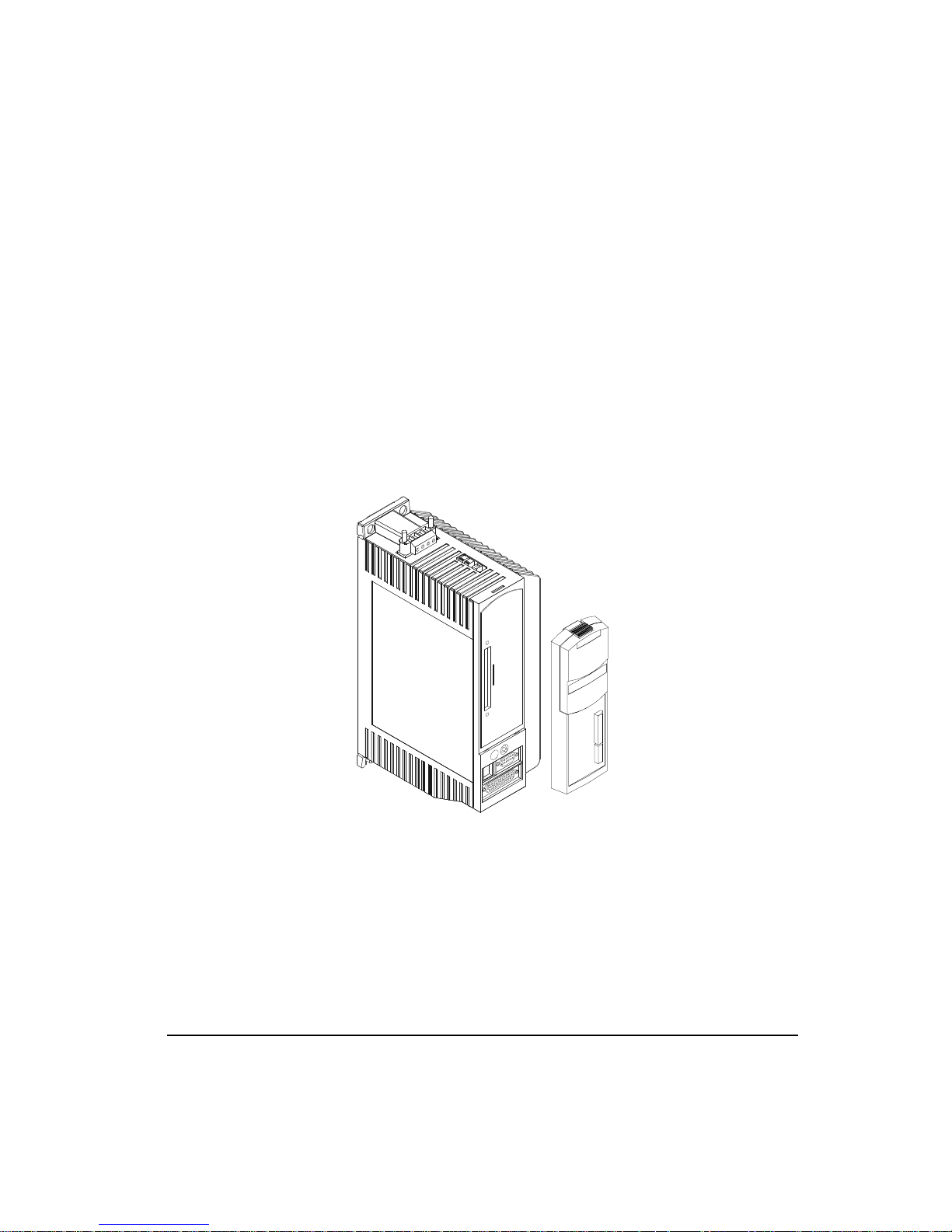
The FM-1 is a compact and rugged module that attaches to the front of the E Series drive. It
provides eight digital input lines and four digital output lines in addition to the four input and
three output lines available on the E Series drive. The FM-1 is setup using PowerTools-FM
software. PowerTools-FM is an easy-to-use Microsoft® Windows®-based setup and
diagnostics tool.
With the FM-1 installed, the base drive functions normally, with some additional features,
including eight more inputs and four more outputs. The additional major features include;
eight digital Torque presets, two additional Summation modes, plus an Alternate Operating
mode function.
FM-1 Speed Module Reference Manual
Introduction
Figure 1: E Series Drive with Function Module FM-1
Velocity Presets
The FM-1 offers eight Velocity Presets which operate the same as E Series drives. These
velocity presets are numbered 0 through 7 and are selectable with I/O. Each preset velocity
has a ramp associated with it, which is used whether the drive has to accelerate or decelerate
to achieve the selected speed.
1
Page 18

FM-1 Speed Module Reference Manual
Digital Torque Preset Mode
A digital torque submode selection has been added to the Torque mode. This offers eight
torque presets which are selectable with I/O or Modbus, and is in addition to the analog
command torque mode available in the base drive.
Summation Modes
Summation mode in the FM-1 has three summation mode choices:
• Analog Velocity + Preset Velocity
• Pulse mode + Analog Velocity
• Pulse mode + Preset Velocity
The Pulse Summation modes are advantageous in applications that require pulse following
plus the ability to adjust the phase relationship to the master by adding or subtracting velocity
to the ratioed master pulse rate. The Analog + Preset Velocity mode operates the same as it
does in the base drive.
Alternate Operating Mode
The FM-1 permits two different operating modes to be set up. It normally runs according to
the Operating Mode but can be switched to the Alternate Operating Mode by activating an
input function. This provides the user with the flexibility to use a drive with the FM-1 in
applications that previously required a complex controller.
Features
• Three Summation modes; Pulse + Analog Velocity, Pulse + Preset Velocity and Preset
Velocity + Analog Velocity
• Eight Velocity Presets
• Eight Torque Presets
• Eight optically isolated input lines
• Four optically isolated output lines
• Easy to attach and detach
• Easy-to-use Windows-based software
• Extensive fault sensing and diagnostics, including storage and time stamping of the last
10 faults
• No tuning needed for no-load to 10:1 inertia mismatch
• High performance tuning based on inertia, friction and response
• Removable I/O connectors for easy installation
2
Page 19
• Scalable Encoder Output
• Travel Limit functions
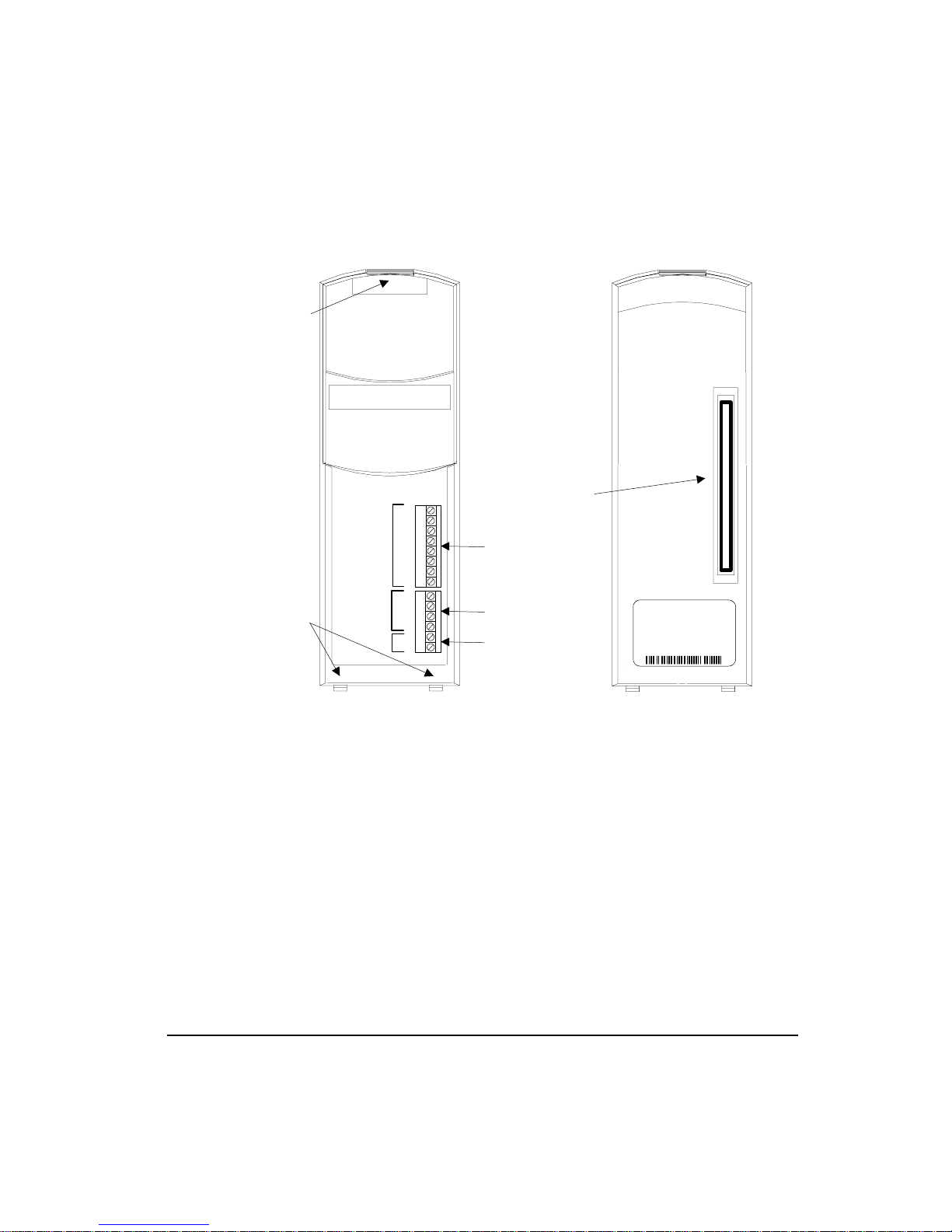
Locking Latch
Introduction
Aligning Tabs
Speed Module
1
Inputs
2
3
4
5
6
7
8
1
Outputs
2
3
4
10-30 VDC
+
-
100-Pin Connector
Inputs
Outputs
10-30 VDC
Front
Figure 2: FM-1 Speed Module Features
MODEL
PART
REV
SER
FM-1
960503-01
EB/09
9820B025
Back
3
Page 20

FM-1 Speed Module Reference Manual
4
Page 21

FM-1 Speed Module Reference Manual
Installing the FM-1
Note
The FM-1 is compatible with all E Series drives with part number 9605xx-05 or higher.
Two aligning tabs, a locking latch and a 100-pin connector are used to attach the FM-1 to the
E Series drive. All electrical connections between the FM-1 and the E Series drive are
accomplished with the single connector located on the rear of the FM-1.
The E Series drive will generate an Invalid Configuration fault (“U” fault) in any of the
following circumstances:
• The first time the FM-1 is installed on an E Series drive and powered up, because it has
not been configured for this drive/motor system.
• Anytime the FM-1 is removed from the E Series drive and the Reset button is pressed then
the FM-1 is reattached to the drive. This is because the drive has been reset and is unaware
of the type of FM that is attached to it.
• When an FM-1 is removed from the drive and another FM-1 is attached to the same drive.
This is because the drive remembers the FM-1’s serial number and will not work with a
different FM-1 until properly reset.
Quick Start
Note
You can remove the FM-1 and reattach it to the same drive without receiving a "U" fault,
only if you do not make any changes to the drive settings.
To reset the fault, create or open a configuration file with the correct drive and motor
selections and download the configuration to the FM-1. If you are certain that the setup data
in the FM-1 matches the drive and motor to which the FM-1 is attached, press and hold the E
Series drive’s Reset button for 10 seconds (until the fault is cleared).
Damage may occur to the drive, motor or both if the fault is cleared using the Reset button
when the setup data in the FM-1 does not match the current drive and motor.
5
Page 22
FM-1 Speed Module Reference Manual
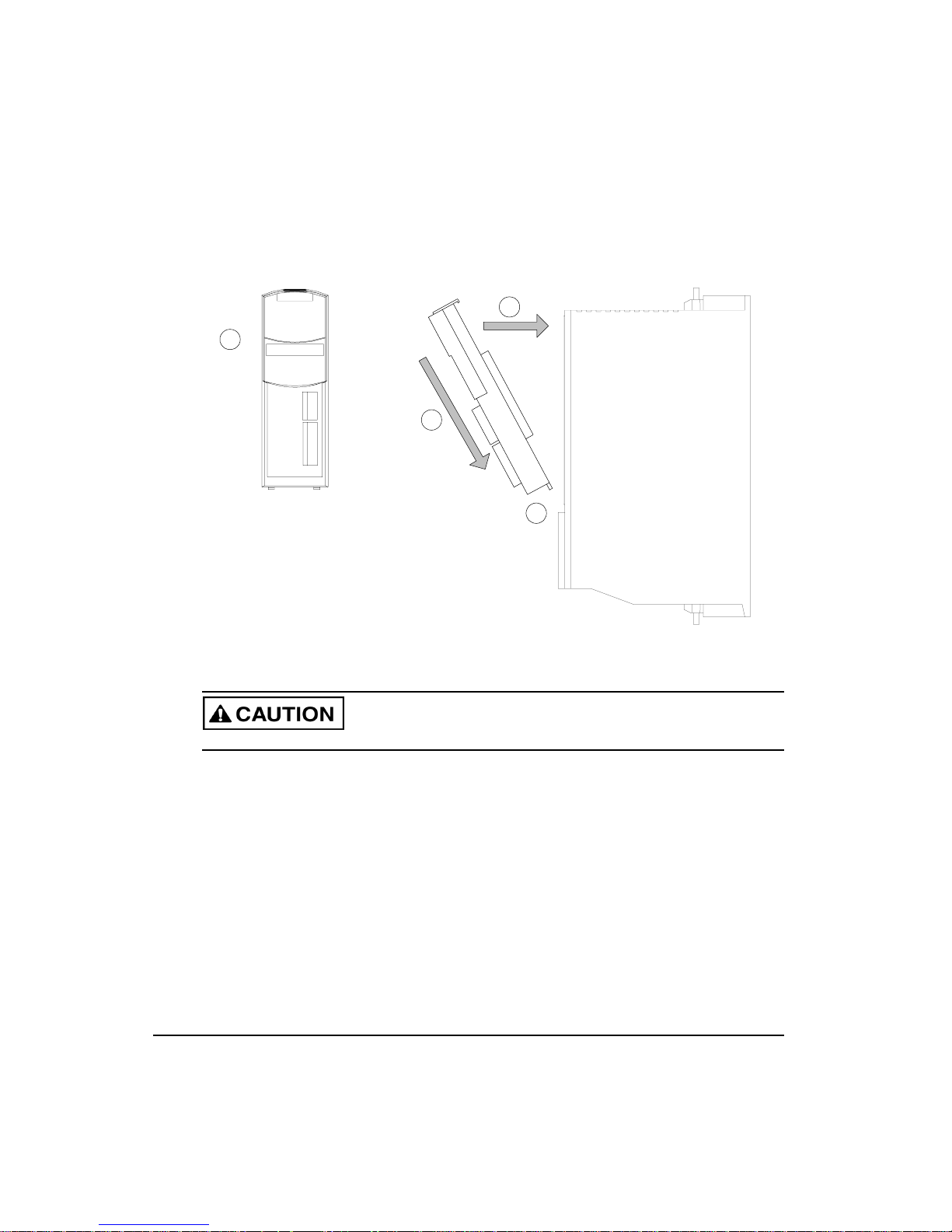
1
Grip the FM
firmly on
each side.
Gently press the
FM against the
drive, aligning the
100-pin connector.
Continue pressing the FM
against the drive until the
latch clicks into the slot
on the top of the drive.
4
3
2
Insert the
aligning tabs
into the slots
on the drive.
Figure 3: Attaching the FM-1 to an E Series Drive
Do not attach or detach the FM-1 when power is applied to the drive.
Electrical Wiring
FM-1’s are equipped with eight optically isolated input lines and four optically isolated
output lines. They are designed to operate from a +10 to 30 VDC source. All outputs are
configured as sourcing and inputs are compatible with sourcing outputs (high = active). You
are responsible for choosing a load that will limit the output current to less than 150 mA each.
The input lines, output lines and I/O power connectors are on removable terminal blocks. 18
to 24 AWG stranded wire is recommended.
A single power supply can be used to power the I/O on both the E Series drive and the FM1, however, it must be wired to both the drive and the FM-1 because I/O power is not passed
through the connector on the back of the FM-1. Alternatively, separate power supplies can be
used to power the I/O on the drive and the FM-1 as long as they share a common ground.
6
Page 23
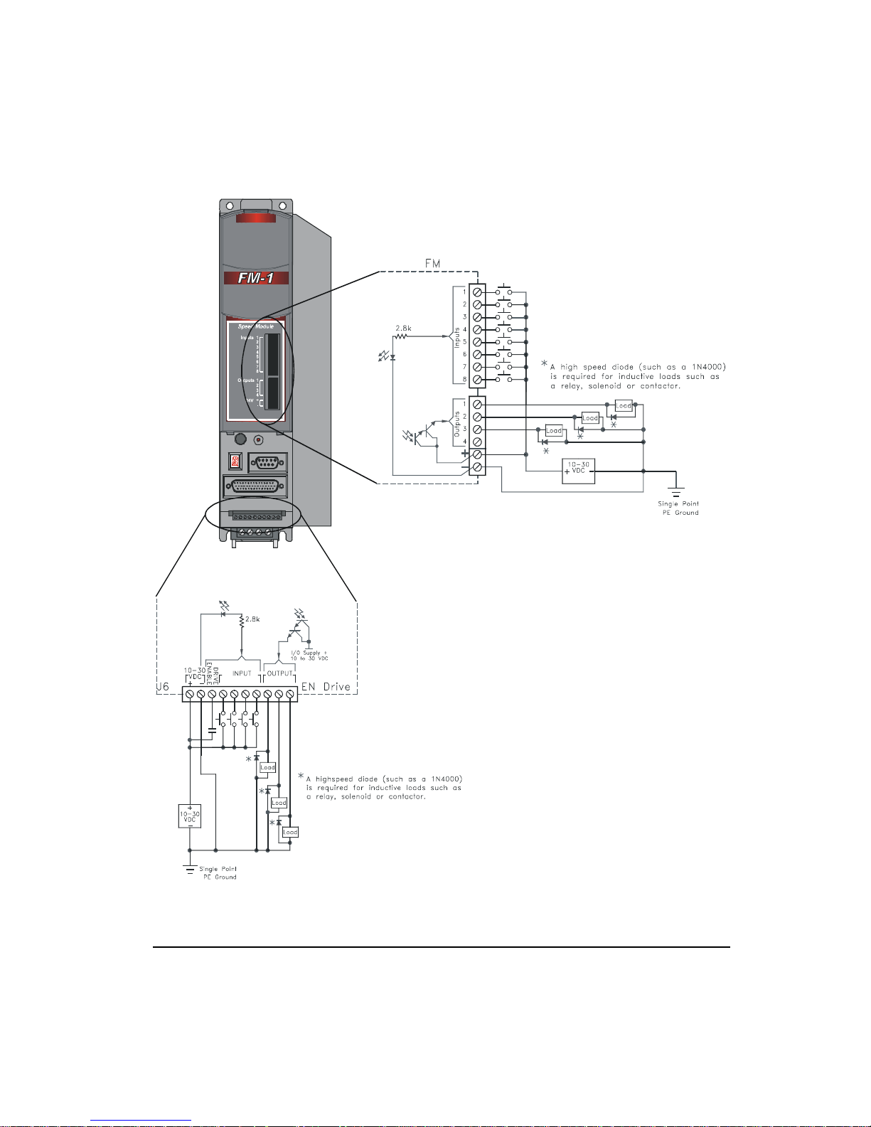
Quick Start
Figure 4: Input/Output Wiring Diagram
7
Page 24

FM-1 Speed Module Reference Manual
Installing the PowerTools-FM Software
Installation Requirements
PowerTools will run on any IBM® personal computer (PC) or compatible with Microsoft
Windows® version 95/98 or NT 4.0, at least 8 MB of RAM, 6 MB of available hard disk
space, one serial port (a second port is required if you are using one for a mouse) and a 3.5
inch floppy disk drive. It is recommended, but not necessary, to use a mouse when operating
PowerTools software.
Installation Procedure
Installing PowerTools-FM is easy. You just insert the appropriate disks and follow the
prompts on the screen. (Please be sure to read every screen before advancing.)
1. Insert disk 1 into drive A.
2. Choose the Run command from the Start menu on the Windows 95 Taskbar.
3. Type A:\setup (substitute the appropriate letter for your floppy disk drive).
4. Follow the instructions on the screen.
Installation will take about five minutes. The install program automatically:
• Creates the directory on your hard drive named:
C:\EMERSON\PTOOLSFM
• Creates a new Windows group called "EMERSON Control Techniques".
• Loads the required DLL’s into your Windows system directory.
• Loads PowerTools-FM into the EMERSON\PTOOLSFM directory.
• Loads FM-1 and E Series drive setup files into the EMERSON\APPS directory.
Note
You may be required to restart Windows 95.
Refer to the readme.txt file located on the installation floppy for more information.
Starting and Exiting
Starting the Software
1. Click the Start button on the taskbar at the bottom left of the screen.
8
Page 25

Quick Start
2. Click on the Programs selection. The Programs menu appears.
3. Click on the “EMERSON Control Techniques” folder icon.
4. Click on the “PowerTools-FM” folder icon.
5. Click on the PowerTools-FM program icon.
Exiting the Software
Choose File from the menubar, then click Exit. If you are using the keyboard, press the
shortcut key combination Alt+F, X.
If you made changes, PowerTools-FM displays an Alert dialog box asking whether you want
to save your current work. Click the Yes button or press Enter to save your work, or click the
No button to quit without saving.
Using Online Help
PowerTools-FM software provides a way for you to find out what each item does without
interrupting your work. To see a definition of a menu command or a dialog box item, click
the Question Mark button in the toolbar, and then click the command or item. You can also
press the F1 key for Help on the active tab.
Also, each tab and dialog box has a Help button that retrieves online help for that tab or dialog
box. You can also use a index-based help system which can search for help based upon a
keyword.
Setting Up the FM-1
This section provides you with step-by-step instructions how to set up your drive using
PowerTools-FM software.
Step 1: Opening an Off-line Configuration Window
To open an off-line Configuration Window, click the New icon from the toolbar or select New
from the File pull-down menu.
9
Page 26
FM-1 Speed Module Reference Manual
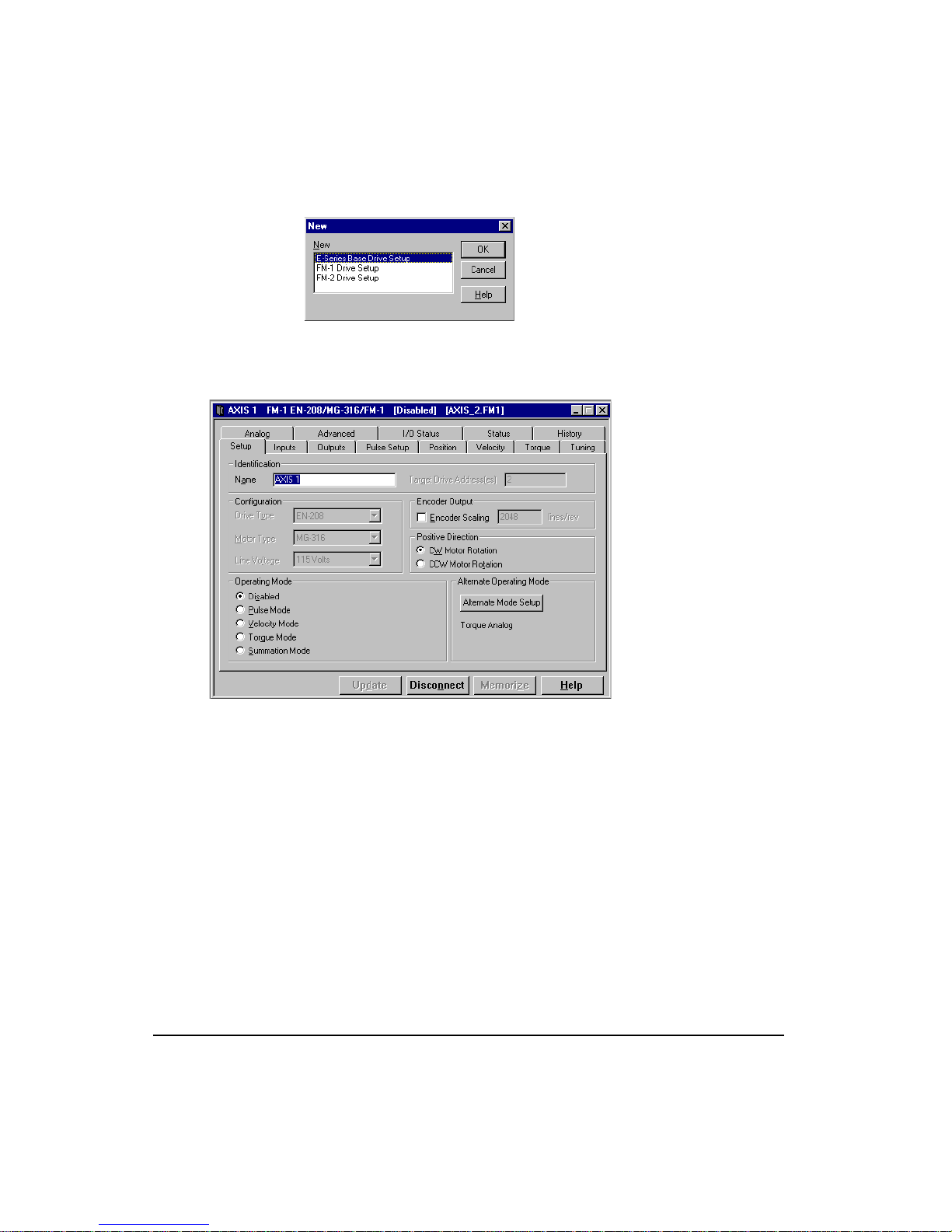
Figure 5: New Dialog Box
When the New dialog box appears, select the FM-1 Drive Setup selection and press the OK
button. A new Configuration Window will be displayed.
Figure 6: Setup Tab
All FM-1 setup parameters are accessible in the twelve tabs of the off-line configuration
window.
This chapter gives an overview of how to setup the four major operation modes and their
submodes.
You can now proceed to set up the FM-1 parameters as desired.
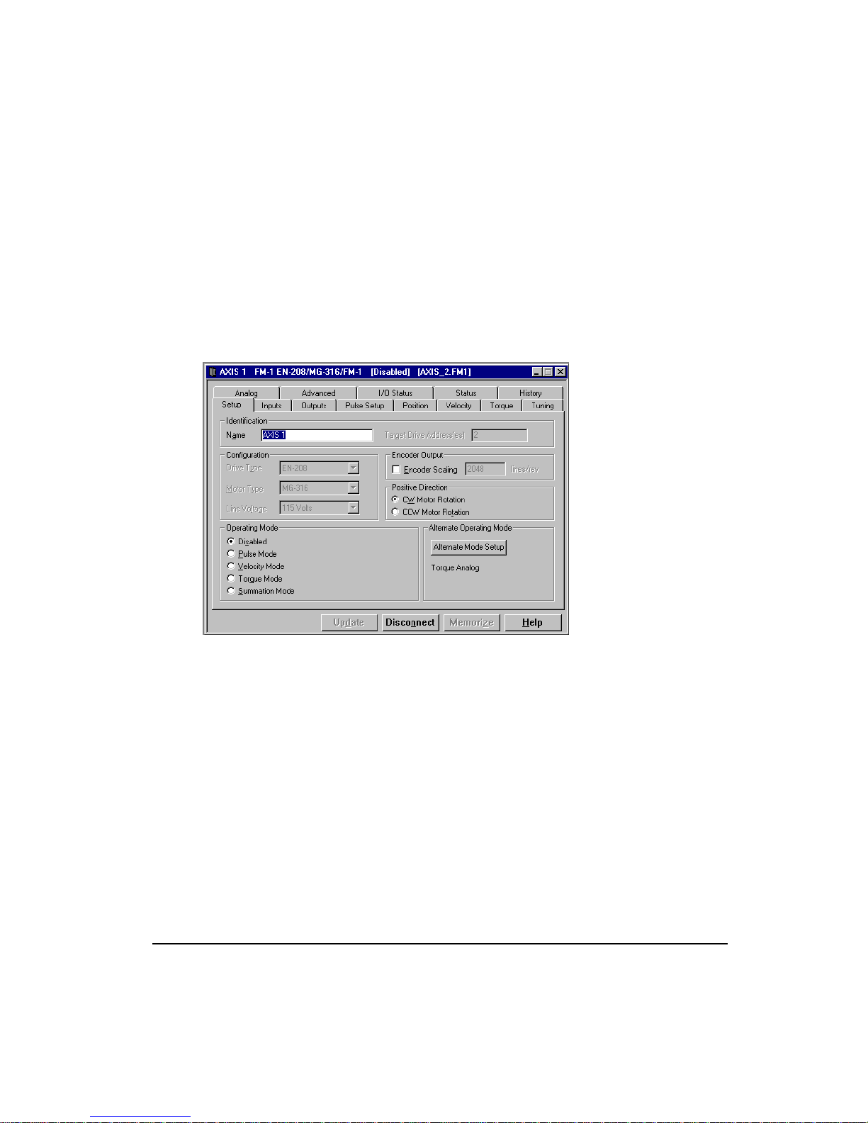
Step 2: General Setup
The Setup tab contains system data such as drive type, motor type, axis name, etc.
10
Page 27

Quick Start
Figure 7: Setup Tab
Entering Identification Parameters:
1. Enter an identifying name in the “Name” box for the FM-1 you are setting up. You can
use up to 24 alpha-numeric characters.
2. Enter the “Target Drive Address(es)” to which you wish to download the setup
information. Unless you have changed the Modbus address of your FM-1, leave this
parameter set to the default value of one.
Entering Configuration Parameters:
1. Click the down arrow of the “Drive Type” list box then select the EN drive model for the
drive you are currently setting up.
2. Click the down arrow of the “Motor Type” list box then select the motor connected to the
drive you are setting up. PowerTools-FM will only display the motor models that are
compatible with the “Drive Type” you selected.
3. Click the down arrow of the “Line Voltage” list box and select the voltage (115 or 230)
with which will be powering the E Series drive.
Entering Positive Direction Selections:
Click which direction, clockwise (CW) or counterclockwise (CCW), to be considered as
motion in the positive direction.
11
Page 28

FM-1 Speed Module Reference Manual
Note
CW and CCW rotation is determined by viewing the motor from the shaft end.
CW Motor Rotation
Select this radio button for applications in which CW motor rotation is considered to be
motion in the positive direction (increasing absolute position).
Figure 8: Clockwise Motor Rotation
CCW Motor Rotation
Select this radio button for applications in which CCW motor rotation is considered to be
motion in the positive direction (increasing absolute position).
Encoder Output Scaling
When enabled, this parameter allows you to set up the drive simulated encoder output to any
integer number of counts per revolution from 100 lines up to the actual motor encoder density.
(2048 lines per revolution is standard for MG motors).
Step 3: Selecting an Operating Mode
Each of the four main operating modes and their related submodes are explained in detail on
page 51.
Alternate Operating Mode
The FM-1 permits two different operating modes to be set up. The Main Operating mode and
the Alternate Operating mode. The Alternate Operating mode is invoked by activating the
input function “Alternate Operating Mode”. The changeover to the Alternate Operating mode
occurs in less than 400 microseconds. Setup of the Alternate Operating mode is similar to the
setup of the Main Operating mode. The Alternate Operating setup is done by pushing the
Setup button inside the Alternate Operating Mode group box on the Setup tab. This opens up
the Alternate Operating Mode dialog box showing the possible operating modes.
12
Page 29
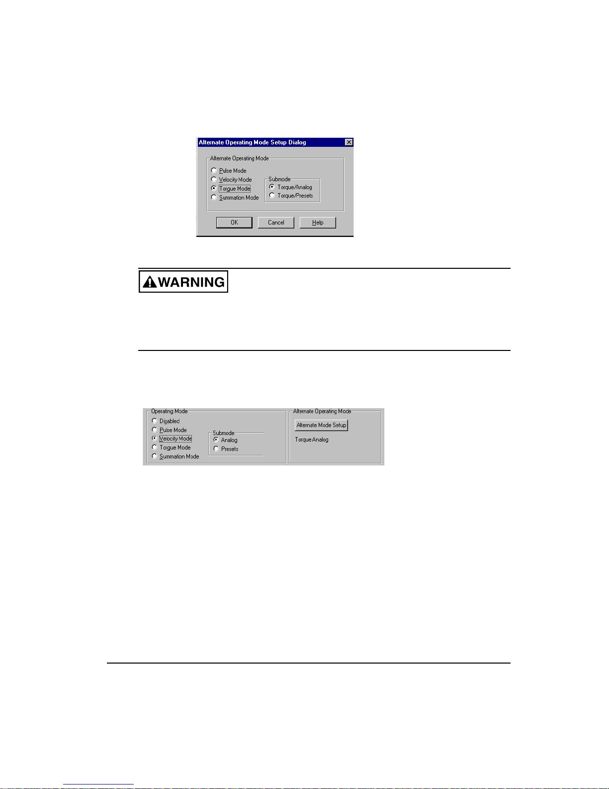
Figure 9: Alternate Operating Mode Setup Dialog Box
You must be very aware of the command inputs that are active during a mode change.
It is possible that the drive can respond very quickly and seem out of control if procedures
appropriate to that changeover are not followed. It is up to the system designer to design
a safe changeover procedure for any particular machine.
Depending on the mode you select, the software will display related submodes and/or
additional parameters that pertain to the main operating mode you selected.
Velocity Analog Submode Setup
Quick Start
Figure 10: Velocity Mode Selection
The following Velocity mode setup procedures assume that you have connected the proper
analog command wiring as described in the “Hardware Installation” section.
1. Select the “Velocity Mode” radio button from the Operating Mode group.
2. Select the “Analog” submode radio button.
3. Go to the “Velocity” tab.
13
Page 30
FM-1 Speed Module Reference Manual
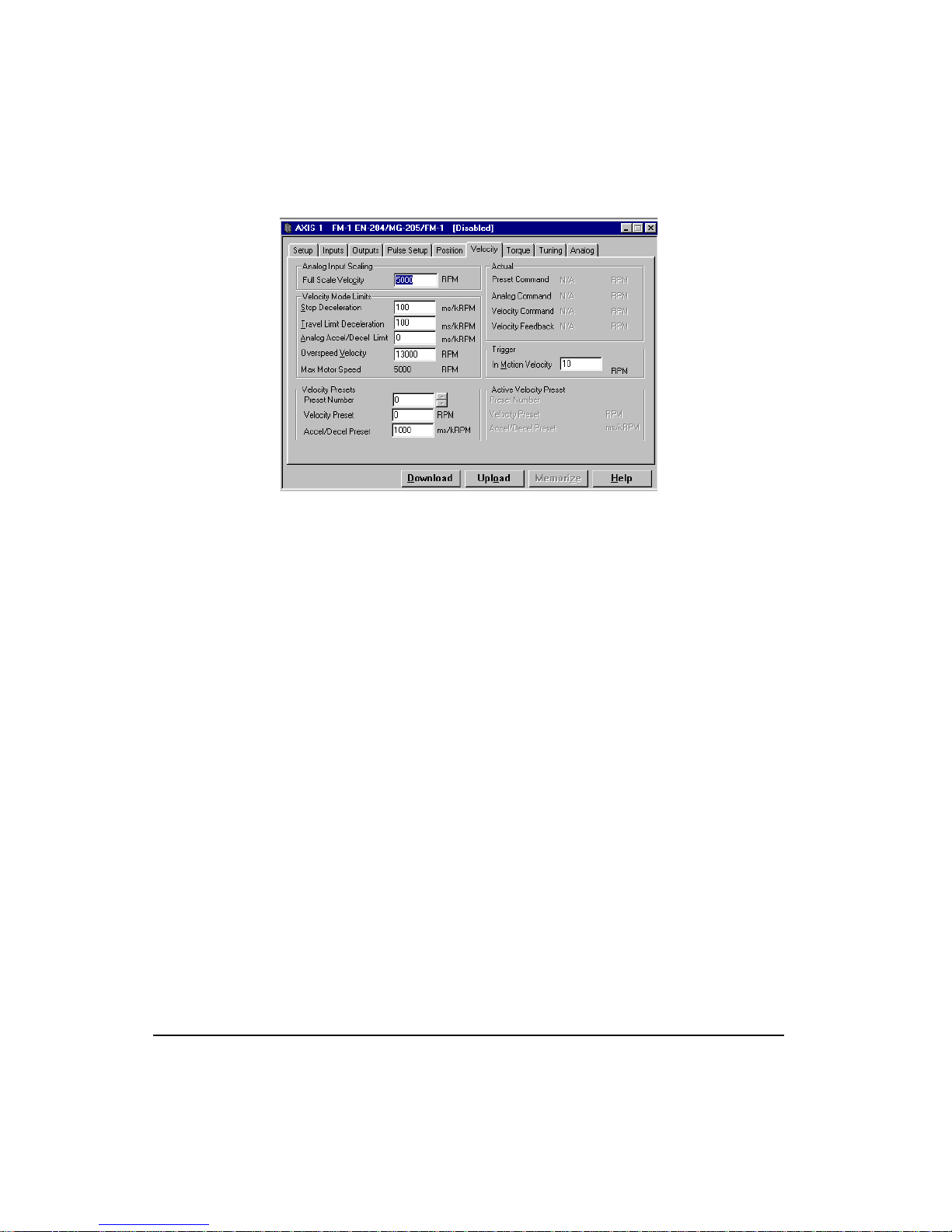
Figure 11: Velocity Tab
4. Enter a “Full Scale Velocity” value (normally left at default value).
5. Enter a “Stop Deceleration” value.
6. Enter a “Travel Limit Deceleration” value.
14
7. Enter a “Analog Accel/Decel Limit” value (normally left at default value).
8. Enter an “Overspeed Velocity” value.
9. Enter an “In Motion Velocity” value (normally left at default value).
10. Go to the Analog tab.
Page 31
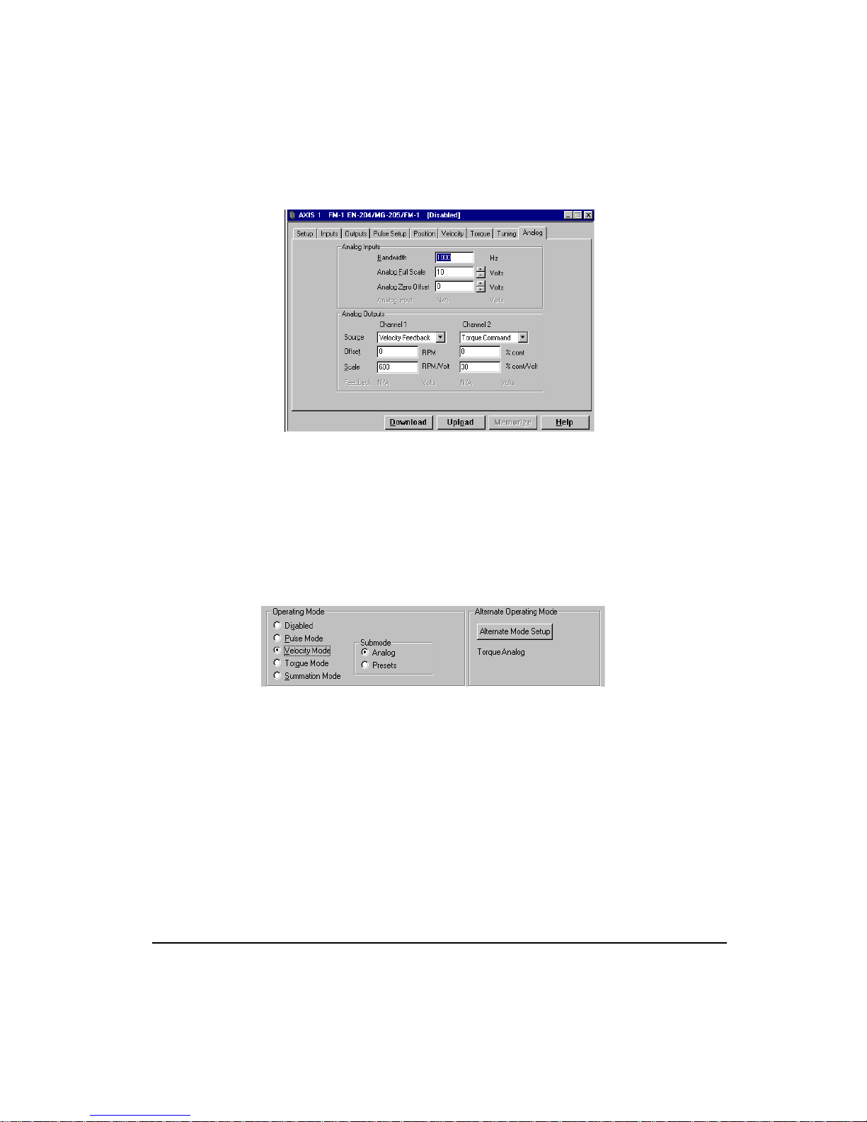
Figure 12: Analog Tab
11. Enter a “Digital Filter Bandwidth” value (normally left at default value).
12. Enter an “Analog Full Scale” value (normally left at default value).
13. Enter an “Analog Zero Offset” value (normally left at default value).
Quick Start
Velocity Presets Submode Setup
Figure 13: Velocity Mode Selected
1. Select the “Velocity Mode” radio button from the Operating Mode group.
2. Select the “Presets” submode radio button.
15
Page 32

FM-1 Speed Module Reference Manual
Figure 14: Velocity Tab
3. Enter a “Stop Deceleration” value.
4. Enter a “Travel Limit Deceleration” value.
5. Enter a value (in RPM) for each of the “Velocity Presets” you wish to use.
16
6. Enter an “Accel/Decel” value (in ms/kRPM) for each of the “Velocity Presets”.
7. Go to Inputs tab.
Figure 15: Inputs Tab
Page 33

Quick Start
8. Assign the Velocity Preset Line #1, #2 and #3 to the desired Input Lines by clicking on
the function and dragging it over to the desired input line. If all the Velocity Preset Lines
are assigned to sequential Input Lines is most convienent .
9. If you wish to make any of the Velocity Preset Line # input functions always active do
not assign them to input lines but, click the “Always Active” check box after clicking on
the desired function.
10. Assign any additional inputs as desired.
Pulse Mode Setup
This procedure assumes that you have connected the proper pulse mode wiring.
1. Select the “Pulse Mode” radio button from the Operating Mode group.
2. Go to the Pulse Setup tab.
Figure 16: Pulse Setup Tab
3. Select one of the "Pulse Interpretation" radio buttons; “Quadrature”, “Direction” or
“Pulse”.
4. Select either the "Differential" or "Single Ended" radio button for the Pulse Source.
5. Enter a “Ratio”. Default is 1.0000 output motor revolution to 8192 input pulse counts.
6. If needed, enable the “Following Error Limit” by checking the “Enable” check box and
enter the desired Following Error Fault Limit value.
17
Page 34

FM-1 Speed Module Reference Manual
Torque Mode Setup
This procedure assumes that you have connected the proper analog command wiring as
described in the "Hardware Installation" section.
Figure 17: Torque Mode Selected
1. Select the "Torque Mode” radio button from the Operating Mode group in the Setup tab.
2. Select Torque submode. "Torque/Analog" for analog command "Torque/Presets" for
digital torque preset mode. For Torque/Presets setup skip to step 8.
3. Go to the Analog tab.
Figure 18: Analog Tab
4. Set "Analog Full Scale" to correspond to "Full Scale Torque" on the Torque tab.
5. Go to the Torque tab.
18
Page 35

Quick Start
Figure 19: Torque Tab
6. Set the "Full Scale Torque" to correspond with "Analog Full Scale" setting on the Analog
tab.
7. Torque/Analog setup complete.
8. Go to Inputs tab.
Figure 20: Inputs Tab
19
Page 36

FM-1 Speed Module Reference Manual
9. Select an "Input Line" radio button that corresponds to the input line you wish to assign
this function to (see “Assigning Input Functions” for additional information) or if you
require the Torque Limit to be always active then do not assign it to an input line, but
instead make the Input Function "Always Active" in the Inputs tab.
10. Assign the Torque Preset Line #1, #2 and #3 to Input Line by dragging and dropping the
Functions onto the Input Line #’s.
11. Go to Torque tab.
20
Figure 21: Torque Tab
12. Enter the desired "Torque Preset" values into the "Torque Preset" selection table.
13. Torque Preset setup is complete.
Torque Limit Setup:
This function can be active in any Operating Mode.
1. Go to Torque tab.
2. Enter a Torque Limit value. This will not be effective until the Torque Limit Active Input
function is set.
3. Go to the Inputs tab.
Page 37

Quick Start
Figure 22: Inputs Tab
Select an "Input Line" radio button that corresponds to the input line you wish to assign this
function to (see “Assigning Input Functions” for additional information) or you require the
Torque Limit to be always active then do not assign it to an input line, but instead make the
Input Function "Always Active" in the Inputs tab.
Torque Level 1 and 2 Setup
This function can be active in any Operating Mode.
1. Click on the Outputs tab.
2. Highlight the “Torque Level 1 Active or Level 2 Active” output function in the “Output
Functions” window.
3. Select an Output Line radio button that corresponds to the output line you wish to assign
this function.
4. Click on the Torque Setup tab.
5. Enter a value into the Torque Level 1 and/or Torque Level 2. The Torque Levels
correspond to the Analog Full Scale parameter, which is defaulted to a 10V analog
command.
Summation Mode Setup
The Summation mode gives you the ability to command the drive from two different
command sources simultaneously which can solve some tricky applications very easily. The
command sources available to be summed are Pulse, Velocity/Analog, and Vel/Presets.
21
Page 38

FM-1 Speed Module Reference Manual
Figure 23: Summation Mode Selected
1. Select the "Summation Mode" radio button from the Operating Mode group.
2. Select the submode desired. This will determine which of the setup sequences you will
follow.
3. If you selected "Pulse + Vel/Analog", use Pulse Mode setup instructions #2 through #6
and Velocity/Analog Mode setup instructions #2 through #13.
4. If you selected "Pulse + Vel/Presets", use Pulse Mode setup instructions # 2 through #6
and Velocity/Preset Mode Setup instructions #3 through #10.
5. If you selected "Vel/Analog + Vel/Presets", use Velocity/Analog Mode setup
instructions #2 through #13 and Velocity / Preset Mode setup instructions #3 through
#10.
Step 4: Assigning Inputs
22
Inputs are assigned in the Inputs tab which is divided into two windows: The Input Functions
window, on the left side, displays the “Input Functions” available, the “Active State” and the
“Always Active” state.
The Input Lines window, on the right side, displays the twelve “Input Lines” (four on the
drive and eight on the FM-1), the “Debounce” value and “Functions assigned ...”.
Page 39

Quick Start
Figure 24: Inputs Tab
Assigning an Input Function to an Input Line:
1. Click on the desired input function in the “Input Functions” window and drag it to the
input line in the “Input Lines” window you wish to assign it to, then release the mouse
button.
2. Alternatively, you can assign an input function to an input line by highlighting the
function, then clicking on the Input Line Selection pull down box and highlighting the
desired input line.
Unassigning an Input Function to an Input Line:
1. Select the desired input function in the “Input Lines” window, then press the Delete key
or select "unmapped" in the Input Line Selection pull down box or drag it from the Input
Lines window and drop it anywhere in the “Input Functions” window.
To Make an Input Function “Active Off”:
1. Select the desired input function in the “Input Functions” window.
2. Click the “Active Off” check box.
To Make an Input Function “Always Active”:
1. Select the desired input function in the “Input Functions” window.
2. Click the “Always Active” check box.
23
Page 40

FM-1 Speed Module Reference Manual
Step 5: Assigning Outputs
Output functions are assigned in the Outputs tab which is divided into two windows: The
“Output Functions” window, on the left side, displays the output functions available.
The "Output Lines" window, on the right side, displays the seven “Output Lines” (three on
the drive and four on the FM-1), the “Active State” and the “Function Assigned ...”.
24
Figure 25: Outputs Tab
Assigning an Output Function to an Output Line:
1. Click on the desired input function in the “Output Functions” window and drag it to the
input line in the “Output Lines” window you wish to assign it to, then release the mouse
button.
2. Alternatively, you can assign an output function to an output line by highlighting the
function, then clicking on the Output Line Selection pull down box and highlighting the
desired output line.
Unassigning an Output Function to an Output Line:
1. Select the desired output function in the “Output Lines” window, then press the Delete
key or select "unmapped" in the Output Line Selection pull down box or drag it from the
Output Lines window and drop it anywhere in the “Output Functions” window.
To Make an Output Line “Active Off”:
1. Select the desired output line in the “Output Lines” window.
2. Click the “Active Off” check box.
Page 41

Quick Start
Step 6: Tuning
Tuning is accomplished in the Tuning Tab where you enter information about the load inertia,
viscous friction, Response required, Integral Gain and other parameters to optimize the
system performance. See "Tuning" section for more information.
Step 7: Communications Setup
Now that the basic FM-1 setup parmeters are entered, it is time to establish communications
with the FM-1 hardware and download the configuration data. Before proceeding, be sure to
connect the serial communication cable between your PC and the E Series drive onto which
the FM-1 is mounted.
The first step in establishing serial communications is to select the com port and the baud rate
using the procedure below:
1. Clicking on the Options pull-down menu.
2. Select the Preferences|Communications option.
3. Select the “Configure Serial Port” option. The Communications Setup dialog box below
will be displayed.
Figure 26: Communications Setup Dialog Box
4. Select the COM port you will be using on your PC and baudrate.
5. Click the OK button.
Note
The default baud rate for all E Series drives is 19200.
Step 8: Downloading the Configuration File
When you are ready to download the information in the current Configuration Window, go to
the Setup tab and enter the address(es) of the drive(s) you wish to download to in the “Target
Drive Address(es)” text box.
25
Page 42
FM-1 Speed Module Reference Manual
You may use commas(,) or spaces( ) to separate individual drive addresses or you may use
hyphens (-) to include all the drive addresses within a range. For example, if you wanted to
download to drives 1, 3, 4, 5, 6, 7 and 9 you could enter the addresses like this: 1,3-7,9.
Note
To download to more than one FM-1, all drive models and motor models must be the same
and any attached FM modules must all be of the same model and firmware revision.
Click the Download button at the bottom of the Configuration Window (or click the
Download icon in the toolbar).
PowerTools-FM will establish communications and transfer all the information in the current
Configuration Window to the FM(s) you select in the Download window.
Note
Downloading will automatically clear an Invalid Configuration Fault (“U” fault).
Step 9: Opening an Online Configuration Window
If you are not already online with the FM-1, use this section to upload a configuration for
online editing.
To open an online Configuration Window, click the Upload icon on the toolbar. PowerToolsFM will display the Scanning dialog while it scans your PC’s serial ports for any compatible
devices.
26
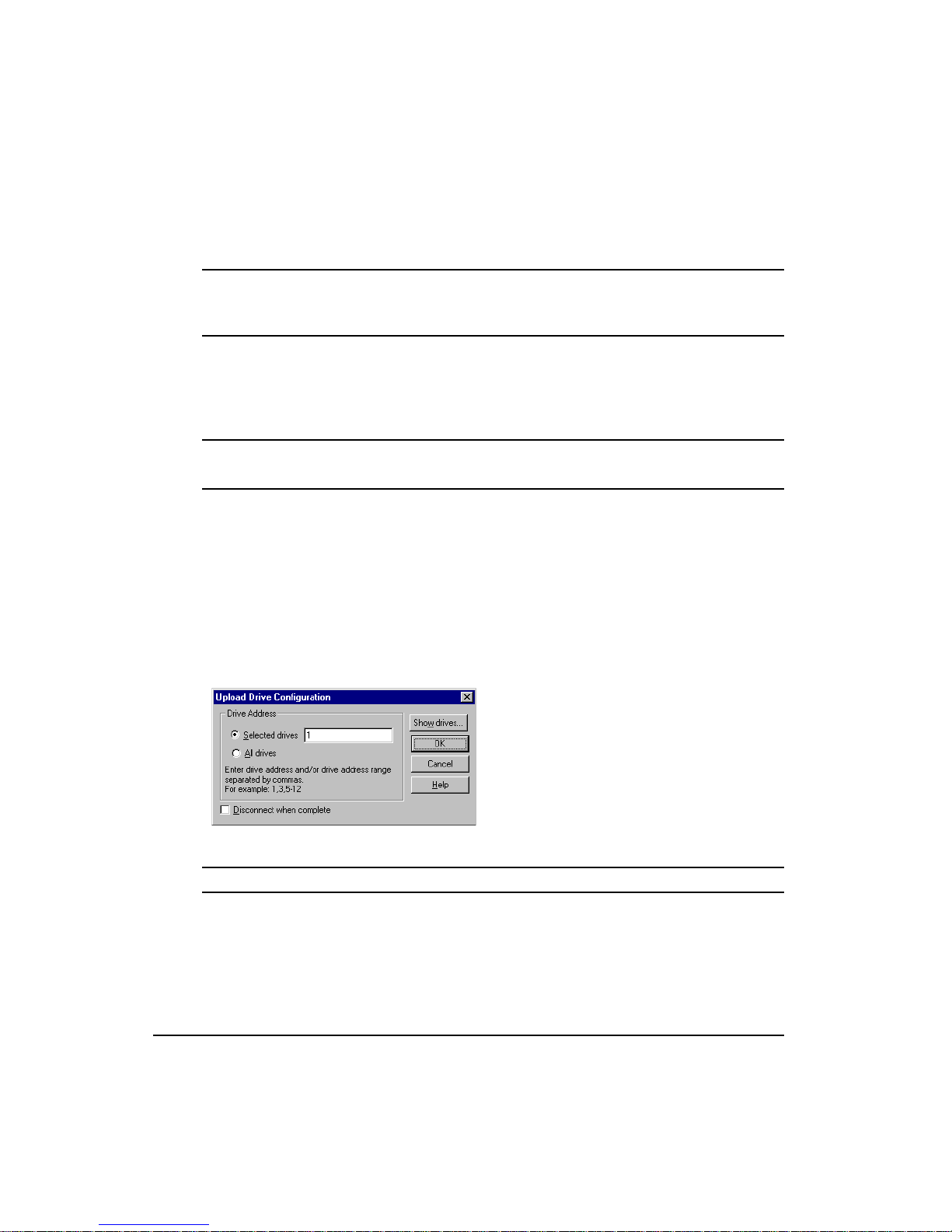
Next, the Upload Drive Configuration dialog box is displayed. This dialog box allows you to
select the device(s) you wish to upload into a PowerTools-FM Configuration Window.
Figure 27: Upload Drive Configuration Dialog Box
Selected Drives
If you have only one device connected, that device’s address will be displayed in the Selected
drives data box. If you have more than one device connected in a multi-drop configuration,
the Selected drives data box will be empty. You can then select either the All drives radio
button or click the Show drives button.
Page 43
Quick Start
All Drives
If you select the All drives option, PowerTools-FM will open a Configuration Window for
each device connected to your PC.
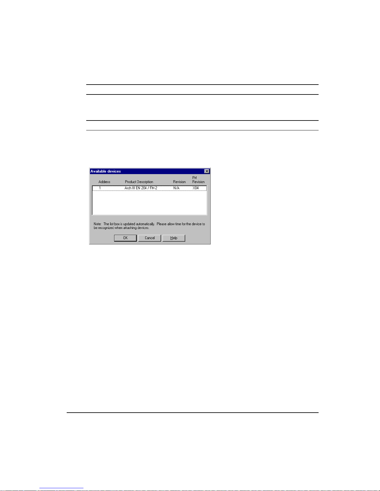
Show drives . . . Button
The Show drives button will display the Available Devices dialog box. This dialog box
displays a list of the devices that are attached to your system (or network). This includes both
Control Techniques and non-Control-Techniques devices. Devices which are not serviceable
by PowerTools-FM software will be grayed.
Figure 28: Available Devices Dialog Box
From this dialog box select the device(s) you wish to upload into a PowerTools-FM
Configuration Window. You can only select non-grayed items. The list box is updated at
regular intervals. Please allow time when connecting and disconnecting devices to the
network. Click the OK button to begin the upload.
Step 10: Operation Verification
After downloading a configuration file to the FM-1 you may want to verify the operation of
the sytem using the checklist below.
1. I/O powered
2. Connections installed
3. The E Series drive enabled
4. “V, T, P or +” displays verified on the E Series drive LED with the decimal point "On"
Step 11: Saving the Configuration File
To save the FM-1 setup information, select Save from the File pull-down menu.
27
Page 44

FM-1 Speed Module Reference Manual
Step 12: Printing the Configuration File
To generate a printed copy of all the data in the FM-1 configuration, select Print from the File
pull-down menu. If you print while online, the print-out will include several pages of useful
online diagnostic information.
Step 13: Disconnecting Communications
After you successfully download to the drive, you may want to disconnect the serial
communications link between the drive and your PC to clear the serial port or to access some
PowerTools options only available when off-line.
To disconnect serial communications, click the Disconnect button at the bottom of the
Configuration Window (or select the Disconnect command from the Device pull-down
menu).
Note
Generally, online mode is used when editing parameters in a FM-1. Off-line editing is
usually only done when not connected to a FM-1.
28
Page 45
FM-1 Speed Module Reference Manual
User Interface
The FM-1 is set up using PowerTools-FM software. PowerTools-FM is an easy-to-use
Windows-based setup and diagnostics tool. It provides you with the ability to create, edit and
maintain your drive’s setup. You can download or upload your setup data to or from an FM-
1. You can also save it to a file on your PC or print it for review or permanent storage.
Operational Overview
Figure 29: PowerTools-FM Setup Tab
How Motion Works
Below is a list of details related to motion in a FM-1.
• The Stop input function overrides motion in all operating modes including Pulse and
Torque mode. It shifts the mode to velocity mode and decelerates the axis according to
the Stop deceleration ramp.
• The Travel limits work in all operating modes including; Pulse, Velocity and Torque
modes.
• When a Travel limit has been activated in a particular direction, uninhibited motion is
allowed in the opposite direction.
• The Positive direction parameter affects all motion by specifying which direction the
motor shaft will rotate when the command is positive (command position is increasing).
29
Page 46

FM-1 Speed Module Reference Manual
• When changing modes with Operating Mode Override input function, no ramping occurs
between the two different commands.
• When using Summation mode, the properties of both modes are honored.
Functional Overview
The E Series drive is a digital servo drive which provides three basic modes of operation:
Pulse, Velocity and Torque. The Operating Mode selection defines the basic operation of the
E Series drive.
With the FM-1 installed, the base drive functions normally, with some additional features,
including eight more inputs and four more outputs. The additional major features include;
four additional Velocity presets, eight digital Torque presets, two additional Summation
modes, and an Alternate Operating mode function.
External control capability is provided through the use of input and output functions. These
functions may be assigned to any input or output line which may be controlled by external
devices, such as a PLC or multi-axis controller to affect the drive operation.
FM-1 parameters can be modified using PowerTools-FM software. All parameters have a
pre-assigned Modbus address which allows you to access them using a Modbus Interface.
All operator programmable parameters and their effect on the drive operation are described
in this section.
Pulse Mode
In Pulse mode the E Series drive will receive pulses which are used to control the position and
velocity of the motor.
Thee pulse interpretations are associated with Pulse mode: Pulse/Pulse, Pulse/Direction and
Pulse/Quadrature. These selections determine how the input pulses are interpreted by the
drive.
Note
High Performance Gains check box in PowerTools software is typically enabled when
Pulse mode is used (default is enabled).
Pulse Source Selection
The E series drive provides two types of pulse input circuits which allow you to choose the
appropriate input type to match the device generating the position pulses. The selection is
done by wiring to the desired input pins of the Command connector J5 and setting the Pulse
Source selection in the Pulse setup Tab. The Differential setting (default) is perfect for most
encoders or upstream drives. The Single Ended setting is a good match for any open collector
driver that requires an external pull up resistors making it ideal for most stepper controllers,
PLC stepper cards and PC computer parallel output printer ports.
30
Page 47

Operational Overview
The two hardware input circuits are included in the drive and are accessible through the drive
command connector. The differential input circuit is RS 422 compatible making it inherently
noise immune while being able to accept pulse rates of up to 2 Mhz per channel. The single
ended inputs use high noise immunity circuitry and have internal pull-up resistors to the
drive’s 5 volt logic supply so external pull-ups and biasing circuitry are not required. When
proper installation techniques are followed as shown below, the differential input setup will
provide a more robust and noise immune system than a single ended input setup.
Differential input is recommended under any of the following conditions:
• Pulse width < 2 µs
• Pulse frequency > 250 kHz
• Pulse command cable length > 25 feet
• Noisy electrical environments
Differential input circuit specifications
Input frequency maximum 2 Mhz
Input device: AM26C32
Input impedance 12 Kohms each input
Max voltage applied to input pins (A, A/) or (B, B/ )
Single ended (referenced to 0V drive logic)+/-10V
Differential ( referenced to mating differential input)+/-10V
Common mode voltage Max +/-7 V
Minimum differential voltage required 200 mV
Input voltage hysteresis 60 mV
Single Ended input circuit specifications
Single ended input specifications:
1 MHz maximum input frequency
Internal 330 ohm pull-up to 5 volt (non-isolated)
1.5 volt low level
3.5 volt high level
Output driver requirements:
15 milliamp sinking (open collector)
5 volt capacity
31
Page 48

FM-1 Speed Module Reference Manual
Signal common connected to Drive Logic 0V (Sync Encoder Common 0V)
ECI-44 terminal
NC2 20 Pulse / Pulse CW / A
NC1 36 Direction Pulse CCW / B
Command
Connector pin #
Pulse-Direction
signal
Pulse - Pulse signal
Pulse Quadrature
signal
Pulse / : Commands motion on the falling edge (active edge).
Direction: Positive (+) motion when high (inactive) and Negative (-) motion when low
(active).
Pulse CW / : Commands positive (+) motion on the falling edge (active edge) of a pulse.
Pulse CCW /: Commands negative (-) motion on the falling edge (active edge) of a pulse.
A and B : Encoder Quadrature signal interpretation. When B leads A Positive (+)
motion commands will be generated, When A leads B, negative (-) motion commands will be
generated.
Pulse/Direction Submode
In Pulse Direction mode pulses are received on the A channel and the direction is received on
the B channel. If the B is high, pulses received on the A are interpreted as positive changes to
the Pulse Position Input. If the B is low, pulses received on the A are interpreted as negative
changes to the Pulse Position Input.
Figure 30: Pulse/Direction Signals
Pulse/Quadrature Submode
In Pulse/Quadrature mode a full quadrature encoder signal is used as the command. When B
leads A encoder counts received are interpreted as positive changes to the Pulse Position
Input. When A leads B encoder counts received are interpreted as negative changes to the
Pulse Position Input. All edges of A and B are counted, therefore one revolution of a 2048
line encoder will produce an 8192 count change on the Pulse Position Input.
32
Page 49

Figure 31: Pulse/Quadrature Signals, + Pulse Input
Operational Overview
Figure 32: Pulse/Quadrature Signals, – Pulse Input
Pulse/Pulse Submode
In Pulse/Pulse mode pulses received on the A channel are interpreted as positive changes to
the Pulse Position Input. Pulses received on the B channel are interpreted as negative changes
to the Pulse Position Input.
33
Page 50

FM-1 Speed Module Reference Manual
Figure 33: Pulse/Pulse Signals
Pulse Mode Parameters
Pulse Position Input parameter shows the total pulse count received by the drive since the last
power up.
The Pulse Position Input, Position Command, Position Feedback Encoder, Encoder Feedback
and Position Feedback are initialized to zero on power-up. Only Position Feedback Encoder
(Encoder Feedback) can be pre-loaded serially with a value after power-up.
The Pulse Mode Ratio parameter includes a numerator which represents motor revolutions,
and a denominator which represents master pulses. The Pulse Ratio Revolutions is allowed
to be negative which reverses all pulse mode motion.
The Pulse Position Input is multiplied by the Pulse Mode Ratio to produce the Position
Command.
34
Following Error/Following Error Limit
The Following Error is the algebraic difference between the Position Command and the
Position Feedback. It is positive when the Position Command is greater than the Position
Feedback. All accumulated Following Error will be cleared when the drive is disabled.
The Following Error Limit is functional in Pulse mode only. A Following Error Limit can be
set using PowerTools or a FM-P. This limit is in motor revolutions and has a range of .001 to
10.000 revolutions. The Following Error Limit can be enabled or disabled.
Pulse Mode Following Error
In Pulse Mode, the range of the Following Error is ±2863.3 revolutions. If the Following
Error Limit is not enabled and the Following Error exceeds 2863.3 revolutions, the displayed
value is limited to this maximum value and will not roll over.
If the Following Error Limit Enable is enabled, the absolute value of the Following Error will
be compared to the Following Error Limit. If the limit is exceeded, a fault will be generated
Page 51

(see Fault section). If the Following Error Limit Enable is disabled, the Following Error Limit
is not used.
Velocity Mode Following Error
In Velocity mode, the maximum Following Error possible varies based on the gain and torque
limit settings. When the Actual Torque Command reaches the maximum possible level, the
following error will stop increasing and any additional position error will be dropped. In
Velocity mode, when the following error exceeds the Following Error Limit parameter there
is no action.
Encoder Feedback and Position Feedback
Encoder Feedback (Position Feedback Encoder) and Position Feedback are two separate
parameters which indicate the same physical motor position. Encoder Feedback is the
position change since power up in motor encoder counts and Position Feedback is the total
position change since power up in motor revolutions.
The Encoder Feedback (Position Feedback Encoder) parameter can be pre-loaded serially by
setting the Position Feedback Encoder Modbus parameter.
Encoder Output Scaling
This feature allows you to change the drive encoder output resolution in increments of 1 line
per revolution up to the density of the encoder in the motor. If the Encoder Output Scaling
parameter is set to a value higher than the motor encoder density, the drive encoder output
density will equal that of the motor encoder. This feature is enabled by checking the Encoder
Output Scaling Enable check box in PowerTools.
You can set it up from the Setup tab in PowerTools-FM or serially, using the Modbus
parameters Encoder Output Scaling and Encoder Output Scaling Enable.
Operational Overview
Figure 34: Encoder Output Phase and Direction Convention
35
Page 52

FM-1 Speed Module Reference Manual
Velocity Mode
Three sub modes are associated with velocity mode: Analog Velocity, Preset Velocity and
Summation Velocity.
Analog Velocity Submode
The drive receives the analog voltage as the Analog Input. The Analog Input is scaled to the
Velocity Command Analog by the Full Scale Velocity, Analog Input Full Scale, and Analog
Input Zero Offset parameters. The equation for this conversion is:
VCA = ((AI + AZO) FSV) / AIFS
Where:
VCA = Velocity Command Analog (RPM)
AI = Analog Input (volts)
AZO = Analog Input Zero Offset (volts)
FSV = Full Scale Velocity (RPM)
AIFS = Analog Input Full Scale (volts)
The Velocity Command is always equal to the Velocity Command Analog in Analog
Velocity mode. The Velocity Command is the command received by the velocity closed loop
control. See "Analog Input" section.
Analog Accel/Decel Limit
This feature in the Analog Velocity mode allows you to limit the accel and decel rate when
using the analog input for velocity control. This makes it very simple to use the drive in high
performance, variable speed, start-stop applications such as Clutch-Brake replacements
without requiring a sophisticated controller to control the acceleration ramps. In applications
which don’t require the drive to limit the ramps such as when using an external position
controller, the parameter can be set to “0” (its default value). If the Accel/Decel limt
parameter value is changed during a ramp, the new ramp limit is imposed within the next
servo loop update.
The Analog Accel/Decel limit parameter is accessed on the Velocity Tab in PowerTools-FM.
Its range is 0.0 to 32700.0 ms/kRPM.
36
Page 53

Operational Overview
Ramp follows command because
command does not exceeed Ramp
Limit value.
Release
Stop
Input
Ramps limited to Ramp Limit value.
Figure 35: Accel/decel Ramp Limits
Preset Velocity Submode
Preset Velocity mode provides up to eight digital Velocity Presets and associated Accel/Decel
Presets. At any time only one Velocity Preset can be selected. They are selected using the
Velocity Preset Line #1, Line #2 and Line #3 input functions (see table below)
Velocity Preset Line #3 Velocity Preset Line #2 Velocity Preset Line #1
000 0
001 1
010 2
011 3
100 4
101 5
110 6
111 7
Selected Velocity and Accel
/ Decel preset #
* (0) = Inactive input function, (1) = Active input function
When one of the Velocity Presets is selected, the Target Velocity is set equal to the Velocity
Preset value and the accel/decel ramp rate is set to the Accel/Decel value associated with that
velocity.
If the Velocity Command Preset is not equal to the Target Velocity, an acceleration (or
deceleration) ramp is in progress. In this state, the Velocity Command Preset will be increased
(or decreased) based upon the acceleration (or deceleration) ramp rate of the selected velocity
preset. During the acceleration/deceleration ramp, the At Velocity output function is inactive.
37
Page 54

FM-1 Speed Module Reference Manual
If the Velocity Command Preset is equal to the Target Velocity, all ramping is complete, the
Velocity Command Preset is constant and the At Velocity output function is active.
The Velocity Command is always equal to the Velocity Command Preset in Velocity Preset
mode.
Figure 36: Velocity vs. Time Diagram using Preset Velocities
Summation Mode
The Summation mode gives you the ability to command the drive with two different
command sources simultaneously which can solve some tricky applications very easily. The
command sources available to be summed are Pulse, Velocity / Analog, and Vel / Presets.
This mode selection is accomplished on the Setup Tab. Choosing the Summation mode radio
button allows you to choose from the three submodes.
Pulse + Vel/Analog Submode
In this mode, the Position Command is added to the Analog velocity command and the result
generates the final motor command. This mode requires that all the parameters for both
modes be set up as if they were to be operated by themselves.
38
Page 55

Operational Overview
The formula is:
Pulse Velocity + Analog Velocity = Velocity Command
This feature is useful in applications where the drive must be geared to a master axis but must
also have the ability to adjust its phase to that master by slightly speeding up or slowing down
while following the master. Many applications such as unwinders with product loop controls
can be simplified by using this Summation mode.
RPM
+ 10 V
- 10 V
1000
900
800
700
600
500
400
300
200
100
1100
1000
900
800
700
600
500
400
300
200
100
1000
1000
900
800
700
600
500
400
300
200
100
100
200
300
400
500
600
700
800
900
0
0
RPM
RPM
0
10 V = 100 RPM
Release Stop Input
10 V = 100 RPM
Release Stop Input
Master
Velocity
Master
Velocity
Summed
Output with
Ratio set to
run follower
at 100 RPM
Summed
Output with
Ratio set to
run follower
at 1000 RPM
Analog
Signal
Input
Time
Time
Time
Figure 37: Velocity in Analog Summation Mode
39
Page 56

FM-1 Speed Module Reference Manual
Example:
The E series drive will drive a motor on a decoiler at a ratio to the master encoder signal to
feed product into a loop. A dancer arm on a potentiometer is monitoring the size of the loop
and trimming the speed of the decoiler motor to maintain a specific loop size. The amount of
trim allowed is easily set by adjusting the Analog Full Scale to the desired value per Full Scale
Velocity.
Pulse + Vel/Presets Submode
In this mode, the Position Command is added to the Preset velocity command and the result
generates the final motor command. This mode requires that all the parameters for both
modes be set up as if they were to be operated by themselves.
40
Page 57

Summation
Output with
Ratio set to
run follower
at 1000 RPM
Summation
Output with
Ratio set to
run follower
at 100 RPM
Preset
Velocity
Selections
2000
1800
1600
1400
1200
1000
800
600
400
200
2000
1800
1600
1400
1200
1000
800
600
400
200
2000
1800
1600
1400
1200
1000
1000
1200
1400
1600
1800
2000
RPM
0
RPM
0
RPM
800
600
400
200
200
400
600
800
Release Stop Input
Release Stop Input
0
(1500)
(1000) (900)
(1000)
Master
Velocity
Master
(600)
(100) (0)
(500)
Preset #1 Preset #0 Preset #2 Preset #4 Preset #0Preset #0
Velocity
(100)
(- 100)
Operational Overview
(1000)(1000)
(600)
Time
(100)(100)
(- 300)
(- 400)
Time
Time
Figure 38: Velocity in Presets Summation Mode
The formula is:
Pulse velocity + Preset Velocity = Velocity command
Example:
The FM-1 will drive a motor on an printing machine at a ratio to the master encoder. This
motor drives a print head that must be in sync with the product to maintain registration and to
41
Page 58

FM-1 Speed Module Reference Manual
prevent smudging of the printed impression. During setup an operator will start the machine
up and adjust the phase of the follower to the master by pushing an Advance or Retard button
until the registration is correct. The Advance button selects Preset Velocity 1 which will be
+50 RPM and the Retard Button selects Preset Velocity #2 which will be -50 RPM. Preset
Velocity #0 will be 0 RPM. In effect when speed #0 is selected, there will be no velocity
added to the Master Pulse rate so the motor follows the master at the Ratio set up in the Pulse
Setup Tab. Note that because the Preset Velocity #0 is digitally set to 0 RPM it will not drift,
so the master phase will never, ever change while Preset Velocity #0 is selected.
When Velocity Preset #1 is selected, +50 RPM is added to the Master Pulse rate thereby
making the motor position advance phase with respect to the master position. When Velocity
Preset #2 is selected, -50 RPM is added to the Master Pulse rate thereby making the motor
position retard phase with respect to the master position. The speed of the phase change is
easily set by setting the Preset Velocities. When the preset velocities are selected with I/O
input functions, the selected velocities will be activated in less than 400 microseconds from
when the Input is activated.
Vel/Analog + Vel/Presets Submode
Velocity Summation mode is defined as the summation of the Velocity Command Analog
and the Velocity Command Preset to produce the Velocity Command. The equation is:
VC = AC + PC
Where:
VC = Velocity Command
AC = Velocity Command Analog
PC = Velocity Command Preset
42
Example 1:
Use of Velocity Presets in a phase advance/retard application. Velocity Preset #0 is set to 0
RPM, Velocity Preset #1 is set to +5 RPM, and Velocity Preset #2 is set to -5 RPM. The
Analog Input is the command source for a web application where a phase adjustment may be
useful. Without interrupting the operation, you may select either Velocity Preset #1 or #2 to
speed up or slow down the motor thereby advancing or retarding the phase between the motor
and the web material.
Example 2:
Use the Velocity Command Analog as a trim adjustment to the digital Velocity Presets.
Velocity Preset #2 is selected with Analog Input at 0, so the Velocity Command Preset and
Velocity Command are equal (set to match a conveyor speed). You can use the Analog Input
(Velocity Command Analog) as a fine adjust for the Velocity Command to exactly match the
conveyor speed.
Page 59

Figure 39: Summation Mode Block Diagram
.
Operational Overview
Figure 40: Velocity vs. Time Diagram, Summation Mode
Torque Mode
The Torque operating mode has the option of two submodes, Analog and Preset.
In this Operating Mode both the position and velocity loops are disabled and only the torque
loop is enabled.
Note
Velocity related faults and velocity related input and output functions are still enabled
(including Stop and Travel Limits).
43
Page 60

FM-1 Speed Module Reference Manual
Torque mode can be entered by specifying the Operating Mode as Torque, or by activating
the input function with Torque mode specified as the Alternate Operating mode.
Torque Analog Submode
In Torque Analog mode the drive receives an Analog Input. The Analog Input is scaled to the
Analog Torque Command by the Full Scale Torque, Analog Input Full Scale, and Analog
Input Zero Offset parameters.
TC = (AI + AZO) x FST / AFS
Where:
TC = Torque Command
AI = Analog Input (volts)
AZO = Analog Input Zero Offset (volts)
FST = Full Scale Torque (%)
AFS = Analog Full Scale (volts)
Torque Preset Submode
These digital preset torque values can be selected with the digital inputs in a binary pattern.
Zero torque is roughly equivalent to disabling the drive. The selected Torque preset is used
immediately with no “ramping” to the torque level.
The repeatability of the actual torque produced at the motor shaft is highly dependent on the
motor and drive temperature. Temperature variation can cause any one particular motor drive
combination to exhibit as much as 10 percent variation in motor torque at the same torque
preset value. Variations of up to 18 percent can be seen between different motor drive
combinations at varying temperatures.
Torque Preset Line #3 Torque Preset Line #2 Torque Preset Line #1 Selected Torque preset #
000 0
001 1
010 2
011 3
100 4
101 5
110 6
111 7
* (0) = Inactive input function
(1) = Active input function
44
Page 61

Operational Overview
Alternate Operating Mode
The FM-1 permits two different operating modes to be setup. The Main Operating Mode and
the Alternate Operating mode. The Alternate Operating mode is invoked by activating the
input function “Alternate Operating Mode”. The changeover to the Alternate Operating mode
occurs in less than 400 microseconds.
Setup of the Alternate Operating mode is similar to the setup of the Main Operating mode.
The Alternate Operating mode setup is done by pushing the Setup button inside the Alternate
Operating Mode group box on the Setup tab. This opens up the Alternate Operating Mode
dialog box showing the possible operating modes.
You must be very aware of the command inputs that are active during a mode change.
It is possible that the drive can respond very quickly and seem out of control if procedures
appropriate to that changeover are not followed. It is up to the system designer to design
a safe changeover procedure for any particular machine.
When using the operating mode override input function to put the drive into Torque
mode, make sure that the Analog Input Voltage is set to the desired level or undesired
motion may occur.
Drive Operation Modifiers
This section describes functions that can modify the operation of the drive.
Stop
The Stop input function, when activated, will cause motion to stop regardless of motor
direction or the operating mode. The Stop Deceleration Ramp defines the rate of velocity
change to zero speed.
Activating the Stop input function causes the drive to change to Velocity mode. Therefore, if
you are operating in Torque mode, the drive must be tuned to the load to prevent instability
when activating the Stop input function.
For example, if an application is operating in Torque mode at 1000 RPM, and the Stop input
function is activated with a Stop Deceleration Ramp of 500 ms/kRPM, the motor will
decelerate to a stop in 500 msec.
45
Page 62

FM-1 Speed Module Reference Manual
When the Stop input function is deactivated, the previous operating mode is restored
within 400 microseconds and the drive and motor will respond immediately with no
ramping unless ramping is part of the selected mode.
Travel Limits
The + and - Travel Limit input functions will stop motion in the direction indicated by the
input function using the Travel Limit Deceleration rate. This feature is active in all modes,
i.e., Velocity, Pulse and Torque modes. When an axis is stopped by a Travel Limit function,
it will maintain position until it receives a command that moves it in the opposite direction of
the active Travel Limit.
The + Travel Limit will stop motion only if the motor is moving + but allows - motion to move
off the limit switch. Conversely, the - Travel Limit will stop motion only if the motor is
moving - but allows + motion to move off the limit switch.
If both input functions are active at the same time, no motion in either direction will be
possible until at least one of the inputs is released.
When either + or - Travel Limit input function is activated, a fault will be logged into the Fault
Log, and the drive will display an “L” on the LED diagnostics display on the front of the
drive. Once the axis is driven off the limit switch, the fault will be cleared and the “L” will
disappear.
If both Travel Limit input functions are activated simultaneously, the drive will respond as if
the Stop input function has been activated and will use the Stop Deceleration ramp.
Travel Limit Application Notes
Torque Mode
If you are operating in Torque mode, the drive must be tuned to the load to prevent instability
when activating the Travel Limit input functions.
Host Controller Travel Limits
If the host controller decelerates the drive faster than the Travel Limit Deceleration ramp, the
drive allows the controller to maintain full control of the axis during the deceleration. This
results in no following error build up in the controller and easier recovery.
Vertical Loads in Velocity mode
In applications with horizontal, counterbalanced or un-counterbalanced vertical loads, the
load will held in position when motion is stopped due to a + or - Travel limit. The position
will be held until the controller commands motion in the opposite direction of the activated
Travel Limit.
46
Page 63

Operational Overview
Vertical Loads in Torque mode
In applications with horizontal or counterbalanced vertical loads, the load will held in position
when motion is stopped due to a + or - Travel limit. The position will be held until the
controller commands motion in the opposite direction of the activated Travel Limit.
When an axis is stopped by the upper Travel Limit with a vertical load, the controller must
maintain a torque command at a minimum level to hold the load or the load may drop.
In applications with un-counterbalanced vertical loads, you must be careful not to set the
controllers torque command to zero when the upper Travel limit is activated. Setting the
controllers analog torque command to zero in this situation will command the axis to move
off the limit switch causing the load to drop.
If your controller removes the torque command (zeroes the analog command output) when a
Travel limit is activated, you have a number of choices to prevent the load from dropping. All
of which require some external logic to determine when the controller can actually take
control again.
• Activate the opposite Travel limit function then release it when the controller is
operational again.
• Activate the Stop input function then release it when the controller is operational again.
• Apply the axis brake then release it when the controller is operational again
Pulse Mode
In applications with horizontal, counterbalanced or un-counterbalanced vertical loads, the
load will be held in position when motion is stopped due to a CW or CCW Travel limit. The
position will be held until the controller commands motion in the opposite direction of the
activated Travel Limit.
When the travel limits are activated, the drive will decelerate at the Travel Limit Deceleration
Ramp and will continue to store all the command pulses received up to ±2
32
counts.The stored
pulses need to be cleared out before the axis will move off the Travel Limit. This can be done
if the controller generates command pulses in the direction opposite the activated Travel limit.
The stored command pulses can also be cleared by activating both Travel Limit input
functions at the same time, activating the Stop input function or disabling the drive for as little
as 5 msec (plus any debounce time).
Torque Limiting
The Torque Command is calculated as shown above, but its value is limited by the Torque
Limit parameter and the current foldback function (see "Torque Limit" and "Current
Foldback" below). The result of this limiting function is Torque Command Actual. This
command drives the Power Stage to generate current in the motor. The Torque Limit Active
47
Page 64

FM-1 Speed Module Reference Manual
output function is active whenever the Torque Command Actual is different from the Torque
Command.
Torque Limit Function
The Torque Limit Enable input function allows an external controller to limit the Actual
Torque Command to a lower value. The Torque Limit parameter is active only when the
Torque Limit Enable input function is active.
T
= PMT, PDT, RFL, SFL or PTL (whichever is lower)
TL
Where:
= Total Torque Limit
T
TL
= Peak motor torque
P
MT
= Peak drive torque
P
DT
= RMS foldback limit (80 percent of continuous motor torque rating)
R
FL
= Stall foldback limit (80 percent of continuous drive current rating)
S
FL
= Programmable Torque Limit
P
TL
Note
The Torque Limit Enable input must be active to use PTL.
If the application requires that the Torque Limit be enabled at all times, the Torque Limit
Enable input function may be set up to be Always Active to avoid the use of an input line.
Velocity Limiting
The drive automatically limits the commanded velocity to a value that is realistically
attainable with the motor when Line Voltage selection is set to 230 VAC.
The Velocity Limiting Active output function will be active if the commanded velocity
exceeds the capacity of the motor/drive currently selected and the line Voltage selection is set
to 230 VAC.
If the Line Voltage parameter is 230 VAC, the velocity limit is equal to 112.5 percent of the
maximum motor speed. If the Line Voltage parameter is 115 VAC, the velocity limit is
disabled.
Note
See the Drive/Motor Specifications table for maximum motor speeds.
Example 1:
If the Motor Type is an MG-316, the maximum motor speed of the MG-316 is 4000 RPM. If
the Line Voltage parameter is set to 230 VAC, and the velocity limit is equal to 112.5 percent
of 4000 RPM or 4500 RPM.
48
Page 65

Operational Overview
Example 2:
If the Motor Type is a MG-316, the maximum motor speed of the MG-316 is 4000 RPM. If
the Line Voltage parameter is set to 115 VAC, the velocity limit is disabled so the Velocity
Limiting Active output will never come on.
Overspeed Velocity Parameter
Motor speed is continuously monitored against the Overspeed Velocity parameter whether
the drive is enabled or not and when the motor speed exceeds the limit, an Overspeed fault
will be activated.
The default value for the Overspeed Velocity Limit is 13000 RPM which effectively disables
the Motor Overspeed detection. The Overspeed Fault will be activated when either one of
these two conditions are met:
1. When the actual motor speed exceeds the Overspeed Velocity Limit parameter.
2. If the combination of command pulse frequency and Pulse Ratio can generate a motor
command speed in excess of the fixed limit of 13000 RPM. In Pulse Mode operation and
any Summation mode which uses Pulse Mode, the input pulse command frequency is
monitored and this calculation is made. For example: with a Pulse Ratio of 10 pulses per
motor revolution, the first pulse received will cause an Overspeed fault even before there
is any motor motion.
In Motion Velocity Parameter
The In Motion Velocity parameter defaults to a value of 10 RPM. If the motor Velocity
Feedback is above the In Motion Velocity value, the In + Motion or In - Motion output
function is active. When the motor velocity falls below one half of the In Motion Velocity,
the In + Motion or In - Motion output function is inactive.
The maximum value for In Motion Velocity is 100 RPM and is intended to be used to indicate
“in motion” not “at speed”.
Note
The In Motion detect is monitored every 400 microseconds so machine jitter and torque
ripple could cause flicker in this signal if the commanded velocity is near the In Motion
parameter value.
Motor Direction Polarity
The direction that the motor turns with a positive command can be changed with a parameter
named Positive Direction. This can be accessed with PowerTools in the Setup Tab. The
positive direction by default causes the motor to turn CW as viewed looking at the shaft
(figure here)
49
Page 66

FM-1 Speed Module Reference Manual
Figure 41: Clockwise Motor Rotation
Positive direction is defined as the command which causes the internal position counter to
count UP. They are:
• A positive analog velocity or torque command i.e. a higher voltage on the (+)
differential input than on the (-) input.
• A positive direction (+) pulse command.
• A positive preset velocity or torque command.
Current Foldback
Current foldback is used to protect the motor and drive from overload. There are two levels
of current foldback: RMS Foldback and Stall Foldback.
RMS and Stall Foldback are displayed on the diagnostic display as a "C" and "c" respectively.
RMS Foldback
RMS foldback protects the motor from overheating. The RMS Foldback parameter models
the thermal heating and cooling of the drive and motor, based on the commanded current and
the motor velocity. On power-up, the RMS Foldback level is zero and is continually updated.
When the RMS Foldback level reaches 100 percent, current foldback is activated and the
Foldback Active output function is active.
Each drive is designed to deliver up to 300 percent of the motor’s continuous torque for no
less the two seconds when running at 100 RPM or more. If only 150 percent of continuous
torque is required, several seconds of operation before RMS foldback is typical.
During current foldback the Torque Command Actual will be limited to 80 percent
continuous motor torque. Current foldback is cancelled when the RMS Foldback level falls
below 70 percent. This could take several seconds or several minutes depending on the load.
The RMS Foldback value is dependent on both torque and velocity. At low speeds (<20
percent of maximum motor speed) the RMS Foldback will closely follow the Torque
Command Actual. At high speeds (>50 percent of maximum motor speed) the RMS Foldback
will read higher than the Torque Command Actual.
50
Page 67

Operational Overview
The time constant for RMS Foldback is 10 seconds. This means that if the load is 150 percent
of continuous, it will take about 10 seconds to reach the foldback trip point.
Figure 42: RMS Foldback Trip Point (this graph is accurate to ±5 percent)
Stall Foldback
Stall Foldback prevents overheating of the Power Stage. It activates in any mode when the
motor velocity is 100 RPM or less and the Torque command causes the current to exceed the
stall current threshold for 100 milliseconds or more.
Note
The stall current threshold is not the same as the drives continuous current rating. For
example, the EN-204 has a continuous rating of 4.5 amps but a stall current threshold of
7amps.
Stall Foldback will also be triggered when the drive sees repeated high currents in one of the
three motor phases. This can occur when a motor is indexed back and forth between two of
its electrical poles.
• For 4 pole motors such as MG-205 or MG-208 this distance is 90° mechanical.
• For 6 pole motors such as MG-316 through the MG-4120 this distance is 60° mechanical.
• For 8 pole motors this distance is 45° mechanical.
Once Stall Foldback is activated, the drive current is reduced to 80 percent of the drive
continuous current rating until the Torque Command Actual is reduced to less than 70 percent
of the drive continuous current rating for about 200 msec or until the motor velocity exceeds
100 RPM.
51
Page 68

FM-1 Speed Module Reference Manual
Shunt Operation
All drive models have internal shunt control. The EN-208 has a 50 ohm, 50 watt internal
resistor and the EN-214 has a 33 ohm, 50 watt internal shunt resistor to dissipate regenerative
energy generated when braking a motor. The EN-204 relies on the bus capacitors to absorb
normal levels of regeneration energy.
Shunt RMS Fault
This fault activates when the RMS power dissipated in the internal shunt resistor is greater
than allowed based on the heatsink utilization and ambient temperature.
Shunt Active Output
This is a real time indicator of the internal shunt control. This output is active on all drives
and indicates when the bus voltage reaches 415 VDC. It is shut off when the bus voltage is
reduced below 385 VDC.
Shunt Control Algorithm
The algorithm used for monitoring shunt utilization accurately determines the shunt resistor
capacity available under various operating conditions. The drive monitors the amount of
power being dissipated by the shunt, and if the power dissipation exceeds the allowable limit
a Shunt Fault is generated. The allowable shunt capacity varies based on the actual drive
loading and ambient temperature.
The heat sink is designed with a certain amount of dissipation capability, and the sum of the
heat generated by the drive bridge rectifier, power module and shunt resistor must be less than
this total capacity. For example, if the drive is operating near its continuous current limit with
o
a 40
C (104oF) ambient, most of the heatsink capacity will be used to dissipate the heat
generated by the output power module and bridge rectifier. In this case the allowable shunt
power will be very low because the capacity is limited by the design.
Conversely, if the drive loading is very low and / or the ambient temperature is reduced, the
capacity to dissipate shunt power is increased. The relationship between the Shunt dissipation
capacity, Heatsink RMS loading and Ambient Temperature is shown in the charts below.
Heatsink RMS
This parameter is available via PowerTools Watch Window as a diagnostic tool. It displays
the effective Heat sink utilization based on the power dissipated by the input bridge rectifier
and the output power stage. The value of 100% is the maximum continuous power dissipation
available at 40
between the Shunt dissipation capacity, Heatsink RMS loading and Ambient Temperature is
shown in the charts below
52
o
C (104oF) ambient temperature with zero shunt activity. The relationship
Page 69

Operational Overview
Drive Ambient Temperature
The Drive Ambient Temperature parameter is located on the PowerTools "Advanced" tab in
the Detailed Setup View. This tab is not normally visible and is only rarely necessary. Use
Options / Preferences to enable it.
The Drive Ambient Temperature is a parameter which will let the drive know the air
temperature around the drive heat sink while the system is under normal operating conditions.
If the actual ambient temperature is higher than 40
Temperature parameter to the actual temperature will help to protect the drive by activating
the Shunt Fault at an appropriate time.
The Drive Ambient Temperature parameter determines the total amount of heat the heat sink
can dissipate. Each Watt of power dissipated will produce an incremental rise in temperature.
So, if the ambient temperature is lower, more wattage can be dissipated before reaching the
temperature limit of the components mounted to the heatsink.
By default, we assume an ambient temperature of 40
temperature for the nominal maximum drive current. If the actual ambient is lower than this,
extra capacity is available for additional shunt power dissipation. Setting the Drive Ambient
Temperature parameter to the actual ambient temperature allows you to take advantage of a
lower temperature and could eliminate the need for an external shunt resistor and controller.
The charts below indicate the operating range for a given ambient temperature.
140%
o
C (104oF), setting the Drive Ambient
o
C (104oF) which is the design ambient
120%
100%
80%
60%
Shunt Power RMS
40%
20%
0%
0% 50% 100% 150%
50 C
40 C
Heatsink RMS
30 C
20 C
Figure 43: EN-208 Shunt Power RMS vs. Heatsink RMS
53
Page 70

FM-1 Speed Module Reference Manual
140%
120%
100%
80%
60%
Shunt Power RMS
40%
20%
0%
0% 50% 100% 150%
Figure 44: EN-214 Shunt Power RMS vs. Heatsink RMS
External Shunt Operation
The DC bus is accessible for applications requiring an external shunt regulator. Control
Techniques offers an external shunt regulator (model #RSR-2) which can provide additional
regenerative power dissipation.
Brake Operation and Wiring
MG motor brake operation is controlled by the Brake Release and Brake Control input
functions. These input functions can be used together to control the state of the Brake output
function. The table below shows the relationship between the Brake input and Brake output
functions (see “Diagnostic Display”).
50 C
Heatsink RMS
40 C
30 C
20 C
Note
No motion should be commanded while the brake is engaged.
Brake Release Input Off On
Brake Control Input On Off On Off
Drive Power
Stage
54
Enabled
Disabled
0111
0011
Page 71

Operational Overview
Brake Release Input Function
The Brake Release input function will release the brake under all conditions. When this input
function is on, the Brake output function will be on (i.e., release brake). This input function
overrides all other brake control, thus allowing the brake to be released while a fault is active
or the power stage is disabled. See also Brake Output function.
Brake Control Input Function
This input function, when active, will engage the brake unless overridden by the Brake
Release input function. This input lets you externally engage the brake while allowing the
drive to also control the brake during fault and disabled conditions.
Brake Output Function
The Brake Output function is used to control the motor holding brake. If the Brake output
function is off, the brake is mechanically engaged. When the brake is engaged, the diagnostic
display on the front of the drive will display a “b”.
The drive outputs are limited to 150 mA capacity, therefore, a suppressed relay is required to
control motor coil. Control Techniques offers a relay, model # BRM-1 (see “Brake Wiring”
for connection diagram).
Analog Input
The Analog Input can be used as a velocity or torque command. The drive accepts a ±10 VDC
differential analog command on pins 14 and 15 of the command connector and has 14 bits of
resolution.
The Analog Input Zero Offset, Analog Input Full Scale and Analog Input Bandwidth
parameters are applied to the Analog Input to generate either an analog velocity or torque
command. These three parameters can be edited using PowerTools, an FM-P or serially using
Modbus.
Analog Input Bandwidth
The Analog Input Bandwidth is used to adjust the maximum frequency of the analog
command signal to which the drive will respond. The units are in Hertz.
Analog Input Full Scale
This parameter specifies the full scale voltage for the analog input. When the drive receives
an analog input equal to the Analog Input Full Scale parameter, the drive will command either
Full Scale Velocity or Full Scale Torque (depending on the operating mode).
55
Page 72

FM-1 Speed Module Reference Manual
Analog Input Calibration
Analog Input Zero Offset is used to null any input voltage that may be present in the
application (default is zero volts). The amount of offset can be read with PowerTools software
or an FM-P using the following procedure:
1. Provide the zero velocity command to the analog input on the command connector.
2. Read the Analog Input Value.
3. Enter the Analog Input Value in the Analog Input Zero Offset.
Analog Command Wiring
56
Figure 45: Analog Command, Differential Wiring Diagram
Page 73
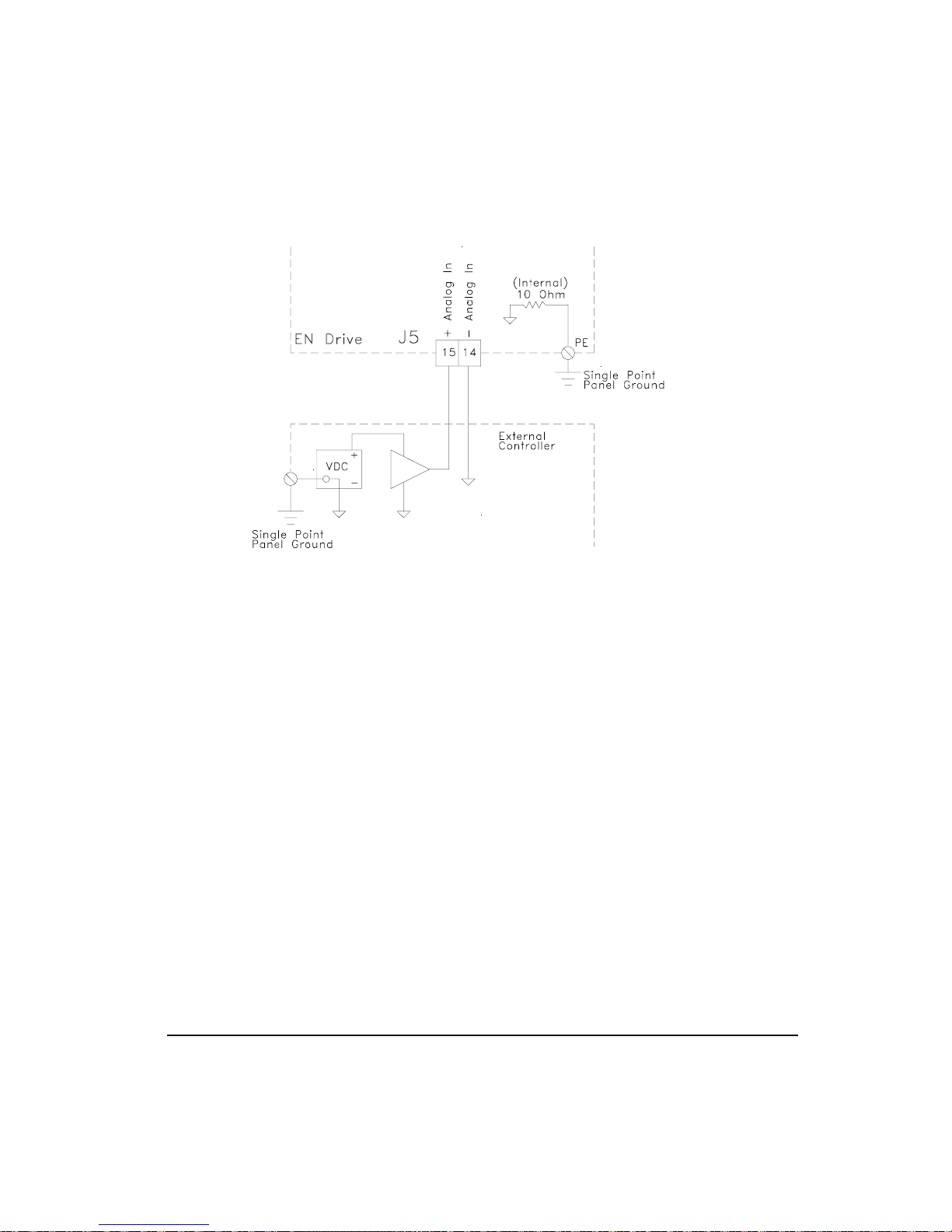
Figure 46: Analog Command, Single-ended Wiring Diagram
Operational Overview
Analog Outputs
The drive has two 10 bit Analog Outputs which may be used for diagnostics, monitoring or
control purposes. These outputs are referred to as Channel 1 and Channel 2. They can be
accessed from the command connector on the E Series drive or from the diagnostics output
pins located on the front of the drive.
Each Channel provides a programmable Analog Output Source.
Analog Output Source options are:
• Velocity Command
• Velocity Feedback
• Torque Command
• Torque Feedback
• Following Error
Default Analog Output Source:
• Channel 1 = Velocity Feedback
57
Page 74

FM-1 Speed Module Reference Manual
• Channel 2 = Torque Command
Output Source Offset Scale
1 Velocity Feedback 0 600 RPM/volt
2 Torque Command 0 30% /volt
Each channel includes a programmable Analog Output Offset and an Analog Output Scale.
This feature allows you to “zoom in” to a desired range effectively increasing the resolution.
The units for both of these parameters is dependent upon the Analog Output Source selection.
Analog Output Offset units:
• Velocity Command = RPM
• Velocity Feedback = RPM
• Torque Command = Percent of continuous torque
• Torque Feedback = Percent of continuous torque
• Following Error = Revs
Analog Output Scale units:
• Velocity Command = RPM/volt
• Velocity Feedback = RPM/volt
• Torque Command = Percent of continuous torque/volt
• Torque Feedback = Percent of continuous torque/volt
• Following Error = Revs/volts
Example:
You could use the Analog Outputs to accurately measure velocity overshoot. For example, to
measure a target velocity of 2000 RPM at a resolution of ±10V = ±200 RPM do the following.
1. Selected Velocity Feedback for the Analog Output Source
2. Set the Analog Output Offset to 2000 RPM
3. Set the Analog Output Scale to 20 RPM/VOLT
This will provide an active range from -10 to +10 Volts to represent 1800 to 2200 RPM.
Therefore, the measured resolution has been increased.
Digital Inputs and Outputs
External control capability is provided through the use of input and output functions. These
functions may be assigned to any input or output line. After they are assigned to lines, external
58
Page 75

Operational Overview
controllers such as a PLC or multi-axis controllers, may be used to affect or monitor the drive
operation.
E Series drives are equipped with five optically isolated input lines (one dedicated to a Drive
Enable function) and three optically isolated output lines. All inputs and outputs compatible
with sourcing signals (active = + voltage) and are designed to operate from a +10 to 30 VDC.
You are responsible for limiting the output current to less than 150 mA for each digital output.
These input and output lines can be accessed through the removable 10 pin I/O connector (J6),
and through the 44-pin command connector (J5).
Note
See “Input/Output And Drive Enable Wiring”.
Input Function Active State
The active state of an input function can be programmed to be “Active Off” or “Active On”
using PowerTools. Making an input function “Active On” means that it will be active when
10 to 30 VDC is applied to the input line it is assigned to and is inactive when no voltage is
applied to the line. Making an input function "Active Off" means that it will be active when
no voltage is applied to the input line and inactive while 10 to 30 VDC is being applied.
You can also make an input function "Always Active", which means that it’s active regardless
of whether or not it is assigned to an input line, and, if you assign it to an input line, it will be
active whether or not voltage is applied to that line. This is useful for testing the drive
operation before I/O wiring is complete.
Input Line Debounce Time
You can program a “Debounce Time” which means the line will need to be active for at least
the debounce time before it is recognized. This feature helps prevent false triggering in
applications with high ambient noise.
Figure 47: Input Line Diagram
59
Page 76

FM-1 Speed Module Reference Manual
Output Line Active State
The default active state of an output line is Active On. This means that the output line will
supply a voltage when the result of the Or’ed output function(s) assigned to that output line
is activated by the drive.
Making an output line "Active Off" means that the line will be “Off” (not conducting) when
the result of the Or’ed output function(s) assigned to that output line is active, and will supply
a voltage when the output function is inactive.
Input Functions
CW and CCW Travel Limit
These input functions cause the drive to decelerate the motor to zero velocity using the Travel
Limit Deceleration ramp.
Stop
This input function causes the motor to decelerate to zero velocity using the Stop Deceleration
ramp. Once stopped, the position will be maintained as long as the Stop input function
remains active.
Reset
This input is used to reset fault conditions and is logically OR’ed with the Reset/Setup Button.
A rising edge pulse is required to reset faults.
Velocity Preset Lines 1, 2 and 3
The Velocity Preset Lines are used to select one of the four pre-defined velocities using the
binary selection patterns shown below.
If you select a different Preset Velocity, the drive will immediately ramp to the new velocity
using the new acceleration ramp without stopping.
Velocity Preset Line #3 Velocity Preset Line #2 Velocity Preset Line #1
000 0
001 1
010 2
011 3
100 4
101 5
110 6
60
Selected Velocity and Accel
/ Decel preset #
Page 77

Operational Overview
Velocity Preset Line #3 Velocity Preset Line #2 Velocity Preset Line #1
111 7
Selected Velocity and Accel
/ Decel preset #
* (0) = Inactive input function
(1) = Active input function
Torque Limit Enable
This input function, when active, causes the Torque Command to be limited to the value of
the Torque Limit parameter.
Operating Mode Override
This input function, when active, will change the operating mode to the mode specified in
"override mode" parameter regardless of the previous operating mode. When this input
function is inactivated, the drive will immediately return to its previous operating mode.
Torque Preset Lines 1, 2 and 3
The Torque Preset Lines are used to select one of the four pre-defined torques using the binary
selection patterns shown below.
If you select a different Preset Velocity, the drive will immediately ramp to the new velocity
using the new acceleration ramp without stopping.
Torque Preset Line #3 Torque Preset Line #2 Torque Preset Line #1 Selected Torque preset #
000 0
001 1
010 2
011 3
100 4
101 5
110 6
111 7
* (0) = Inactive input function
(1) = Active input function
Brake Release
This input function will release the brake under all conditions. If this input function is active,
the brake output function is switched to active (i.e. release brake). This overrides all other
brake control, thus allowing the brake to be released while a fault is active or the power stage
is disabled.
61
Page 78

FM-1 Speed Module Reference Manual
Brake Control
This input function, when active, will engage the brake unless overridden by the Brake
Release input function. This input function lets you externally engage the brake, while
allowing the drive to also control the brake during fault and disabled conditions.
Output Functions
CW and CCW Travel Limit
These outputs are active when the associated Travel Limit input function are active.
Brake
This output function is used to control the motor holding brake. If the Brake output is “Off”,
the brake is mechanically engaged.
Foldback Active
This output function is active when the drive is limiting motor current. If the RMS Foldback
value exceeds 100 percent of the continuous rating, the current foldback circuit will limit the
current delivered to the motor to 80 percent of the continuous rating.
62
Drive OK
This output function is active whenever no fault condition exists. Travel limits and the Drive
Enable have no effect on this output function.
In CW Motion
This output function is active whenever the motor is turning at a velocity greater than the In
Motion Velocity parameter in the CW direction. Default value of In Motion Velocity is 10
RPM. Hysteresis is used to avoid a high frequency toggling of this output function. This
function is deactivated when the motor velocity is less than 1/2 of the In Motion Velocity
parameter.
Power Stage Enabled
This output is active when the drive is OK and enabled. It will go inactive when anything
happens to disable the output power stage.
Page 79

Operational Overview
In CCW Motion
This output function is active whenever the motor is turning at a velocity greater than the In
Motion Velocity parameter in the CCW direction. Default value of In Motion Velocity is 10
RPM. Hysteresis is used to avoid a high frequency toggling of this output function. This
function is deactivated when the CCW motor velocity is less than 1/2 of the In Motion
Velocity parameter.
Fault
This output function is active whenever a drive fault condition exists. The Travel Limits will
also cause this output function to be active.
At Velocity
This output function is active whenever the motor is at the desired velocity (i.e., acceleration
or deceleration is complete). This output is only associated with Velocity Preset Velocities.
Torque Limit Active
This output is active if the Torque Command exceeds the specified Torque Limit value.
Velocity Limiting Active
This output function is active when the Actual Velocity Command is being limited. The
velocity limit is dependent upon the maximum motor speed for the Motor Type selected and
the Line Voltage.
If the Actual Velocity Command exceeds the velocity limit, the command will be limited and
the Velocity Limiting Active output function will be active.
Shunt Active
This is a real time indicator of the internal shunt activity. For EN-204 and Epsilon drives, this
output can be used to control all external shunt control switches.
63
Page 80

FM-1 Speed Module Reference Manual
64
Page 81

Setup Tab
This default tab is displayed each time you open the PowerTools software. This tab allows
you to set most of the parameters needed to configure your drive, with the exception of the
digital Input and Output I/O functions.
All the setups here are effective for all modes used and for both the (Main) Default Operating
Mode and the Alternate Operating Mode.
FM-1 Speed Module Reference Manual
Setting Up Parameters
Figure 48: Setup Tab
Identification Group
Name
Enter a 24-character alpha-numeric name for the drive you are currently setting up. Assigning
a unique name for each drive in your system allows you to quickly identify a drive when
downloading, editing and troubleshooting. All keyboard characters are valid.
Target Drive Address(es)
Enter the Target Drive Address(es) you wish to download the setup information to (or upload
from).
65
Page 82

FM-1 Speed Module Reference Manual
To download to more than one drive simultaneously, separate the drive addresses with
commas, spaces or hyphens. Individual drive addresses need to be separated by commas or
spaces. Sequentially numbered groups of addresses can be specified with a hyphen between
the first and last address of the group (i.e., 1-4 = 1, 2, 3, 4). If you download to more than one
drive simultaneously, they must all be the same drive and motor model and have the same
firmware revision.
Configuration Group
Drive Type
Select the E Series Drive model for the drive you are currently setting up. PowerTools
software will only display the motor models that are compatible with the EN Drive you
selected and any user defined motors.
Motor Type
Select the motor you wish to use. PowerTools software will only display the motor models
that are compatible with the EN Drive you selected and any user defined motors.
Line Voltage
Line Voltage specifies the applied power and adjusts the internal gains to compensate for it.
This parameter has two choices 115 VAC and 230 VAC. If the Line Voltage is set to 230
VAC when the actual applied voltage is 115 VAC, the motor will be slightly less responsive
to commands and load disturbances.
The Line voltage must never be set to 115 VAC if the applied voltage is actually 230
VAC. This can cause drive instability and failure.
Encoder Output Group
Encoder Scaling Check Box
This check box enables the Encoder Output Scaling feature. When not enabled, the encoder
output density is the same as the actual motor encoder.
Encoder Scaling
This feature allows you to change the drive encoder output resolution in increments of 1 line
per revolution up to the density of the encoder in the motor. If the Encoder Output Scaling
parameter is set to a value higher than the motor encoder density, the drive encoder output
density will equal that of the motor encoder.
66
Page 83

Setting Up Parameters
Positive Direction Group
CW Motor Rotation Radio Button
This defines that the motor will rotate clockwise when given a positive velocity, torque or
position command. CW/CCW is defined when facing the motor output shaft.
CCW Motor Rotation Radio Button
This defines that the motor will rotate counterclockwise when given a positive velocity,
torque or position command. CW/CCW is defined when facing the motor output shaft.
Operating Mode Group
Disabled Radio Button
Selecting this button sets the drive into a disabled mode. No other parameters are affected.
The Hardware Enable input will not enable the drive.
Pulse Mode Radio Button
Selects the Pulse operating mode with the option of three Pulse modes. The three options are
selectable in the Pulse setup Tab.
Velocity Mode Radio Button
Selects the Velocity operating mode with the option of two submodes, Analog and Preset. The
two options show up as radio buttons in the Setup Tab after the Velocity mode is selected.
Figure 49: Setup Tab, Velocity Submodes
67
Page 84

FM-1 Speed Module Reference Manual
Analog Submode Radio Button
Selects the Velocity Analog operating mode.
Presets Submode Radio Button
Selects the Velocity Presets operating mode.
Torque Mode Radio Button
Selects the Torque operating mode with the option of two submodes, Analog and Preset. The
two options show up as radio buttons in the Setup Tab after the Torque mode is selected.
Figure 50: Setup Tab, Torque Submodes
Torque/Analog Submode Radio Button
Selects the Torque / Analog operating mode.
Torque/Presets Submode Radio Button
Selects the Torque / Presets operating mode
68
Summation Mode Radio Button
Selects the Summation operating mode with the option of three submodes. The three options
are selectable in the Setup Tab after the Summation Mode is selected.
Figure 51: Setup Tab, Summation Submodes
Pulse + Vel/Analog Submode Radio Button
Selects the Pulse + Vel/Analog operating mode
Pulse + Vel/Presets Submode Radio Button
Selects the Pulse + Vel/Analog operating mode
Page 85

Setting Up Parameters
Vel/Analog + Vel/Presets Submode Radio Button
Selects the Vel/Analog + Vel/Presets operating mode
Alternate Operating Mode Group
Alternate Operating Mode Button
This button launches the Alternate Operating Mode dialog box for the Alternate Operating
Mode function. This will then allow you to set up a second operating mode, which can be
selected with the input function “Alternate Operating Mode". The Disabled mode is not an
alternate mode option.
Figure 52: Alternate Operating Mode Setup Dialog
Inputs Tab
This tab is divided into two windows: The “Input Functions” window, on the left side,
displays the ten input functions available, the function polarity and the always active state.
The “Input Lines” window, on the right side, displays the four input lines on the base drive
and the eight input lines on the FM, the drive enable input, the debounce value and input
function assignments.
69
Page 86

FM-1 Speed Module Reference Manual
Figure 53: Inputs Tab
All the setups here are effective for all modes used and for both the (default) Default
Operating Mode and the Alternate Operating Mode.
Input Functions Window
70
This window allows you to select the input function you wish to assign to an input line. After
selecting a function you can also set the Active State and Always Active flag by clicking the
Always Active and Active Off check boxes.
Input Line Selection
This list box allows you to assign or unassign the currently highlighted Input Function to an
Input Line. Click on the list box arrow to see the possible assignment lines. Then click on one
of the line numbers to assign the function. This list box would normally be used when a mouse
is not available to navigate the software. Assigning the input functions can also be
accomplished by dragging the Input Function and dropping it onto an Input line.
Active Off Check Box
This check box allows you to change the “Active On/Off” state. Select the desired function
in the input functions window, then check or uncheck the “Active Off” checkbox.
Making an input function “Active On” means that it will be active when 10 to 30 VDC is
applied to the input line it’s assigned to and is inactive when no voltage is applied to the line.
Making an input function “Active Off” means that it will be active when no voltage is applied
to the input line and inactive while 10 to 30 VDC is being applied.
Page 87

Always Active Check Box
This check box is used to make an input function “Always Active”. When you make an Input
Function always active, it’s active whether assigned to an input line or not. If you make an
input function “Always Active” then assign it to an input line, that function will be active
whether or not voltage is applied to the line it’s assigned to.
Input Lines Window
This window displays the four input lines on the base drive and the eight inputs on the FM,
the drive enable input, the debounce value and input function assignments. The input line
debounce time is changed by selecting the desired input line in this window, then entering the
debounce time in the edit field below.
Debounce
This feature helps prevent false input triggering in applications with high ambient noise. Enter
a “Debounce Time” in milliseconds. The value entered here is the minimum amount of time
the input line will need to be active before it is recognized as a valid input and the minimum
amount of time it will need to be inactive before it is recognized as inactive.
Outputs Tab
Setting Up Parameters
This tab is divided into two windows: The “Output Functions” window, on the left side,
displays the available output functions. The “Output Lines” window, on the right side,
displays the three output lines of the base drive and the four outputs on the FM, the line Active
State (on or Off) and the output function assignments.
71
Page 88

FM-1 Speed Module Reference Manual
Figure 54: Outputs Tab
All the setups here are effective for all modes used and for both the (default) Default
Operating Mode and the Alternate Operating Mode.
Note
For wiring information, refer to the Hardware Installation section of the E Series Drives
Installation Manual (P/N 400500-01), or the E Series Drives Reference Manual (P/N
400501-01).
72
Output Functions Window
This window allows you to select the output function you wish to assign to an output line.
Output Line Selection
This list box allows you to assign or unassign the currently highlighted Output Function to an
Output Line. Click on the list box arrow to see the possible assignment lines. Then click on
one of the line numbers to assign the function. This list box would normally be used when a
mouse is not available to navigate the software. Assigning the output functions can also be
accomplished by dragging the Output Function and dropping it onto an output line.
Output Lines Window
This window displays the three output lines on the base drive and the four outputs on the FM,
the function assignments and the active state. The output line active state is changed by
Page 89

selecting the desired output line in this window, then clicking the Active Off check box below
this window.
Active Off Check Box
The default active state of an output line is Active On. This means that the output line will
output a voltage (exact voltage is determined by your I/O power supply) when the result of
the logical OR’ed output functions assigned to that line is active.
Making an output line “Active Off” means that the line will be off (not conducting) when the
assigned output function(s) is active, and will supply a voltage when the output function(s) is
inactive.
To change the active state of an output line, select the desired line in the Output Lines
window, then check or uncheck the Active Off checkbox.
Pulse Setup Tab
This tab is where you will setup the details pertaining to the Pulse operating modes. Here you
will set up the type of pulses received, the type of input hardware interfacing, the following
error limits, and the follower ratio. All the setups here are effective for all Pulse modes used
and for both the (Main) Default Operating Mode and the Alternate Operating Mode.
Setting Up Parameters
Figure 55: Pulse Setup Tab
All the setups here are effective for all modes used and for both the (Main) Default Operating
Mode and the Alternate Operating Mode.
73
Page 90

FM-1 Speed Module Reference Manual
Pulse Interpretation Group
Quadrature Radio Button
Selects the Pulse Quadrature type of pulse input interpretation. This is effective whether you
are using the differential or single ended inputs. In this mode all rising and falling edges input
on channels A and B are counted effectively multiplying the lines per channel by 4.
Direction Radio Button
Selects the Pulse Direction type of pulse input interpretation. This is effective whether you
are using the differential or single ended inputs. In this mode, each rising edge of A channel
(or falling edge of A/) is counted as one command pulse.
Pulse Radio Button
Selects the Pulse Pulse type of pulse input interpretation. This is effective whether you are
using the differential or single ended inputs. In this mode each rising edge of the A channel
(or falling edge of A/) is counted as 1 command pulse CW and each rising edge of the B
channel (or falling edge of B/) is counted as 1 command pulse CCW.
Pulse Source Group
Differential Radio Button
Selects the differential hardware input of the drive to receive pulses (default) these pulse
inputs are as follows:
ECI-44 terminal
Sync Enc In “A” 27 Pulse Pulse + A
Sync Enc In “A/” 41 Pulse/ Pulse +/ A/
Sync Enc In “B” 40 Direction Pulse - B
Sync Enc In “B/” 26 Direction/ Pulse -/ B/
Command
Connector pin #
Pulse-Direction
signal
Pulse-Pulse signal
Single Ended Radio Button
Selects the differential hardware input of the drive to receive pulses (default) these pulse
inputs are as follows:
ECI-44 terminal
NC2 20 Pulse / Pulse + / A
NC1 36 Direction Pulse - / B
Command
Connector pin #
Pulse-Direction
signal
Pulse - Pulse
signal
74
Pulse Quadrature
signal
Pulse Quadrature
signal
Page 91

Setting Up Parameters
Limits Group
Following Error Check Box
Check this box to enable or disable the Following Error Limit.
Following Error
The Following Error is the difference between the Position Command and the Position
Feedback. It is positive when the Position Command is greater than the Position Feedback. If
the absolute value of the following error exceeds the value you enter here, the drive will
generate a Following Error Fault (F) and the drive will be disabled. All accumulated
Following Error will be cleared when the drive is disabled.
The Following Error Limit is in motor revolutions and has a range of .001 to 10.000
revolutions.
Ratio Group
Ratio Revolutions
Sets up the number of motor revolutions that will be commanded per number of Ratio Counts
received from the master. This parameter can be a negative value, which will reverse the
commanded motor direction. The resolution is .0001 revolutions. Maximum effective ratio is
20 counts per motor revolution
Ratio Counts
Sets up the number of pulse input counts that will produce the number of motor revolutions
in Ratio Revolutions. This parameter cannot be a negative value and the resolution is 1 count.
Maximum effective ratio is 20 counts per motor revolution
Position Tab
This tab allows you to enable and define Following Error Limit and view Actual Drive data
associated with Pulse mode. Actual Drive data is only enabled if the drive is on line with your
PC.
75
Page 92
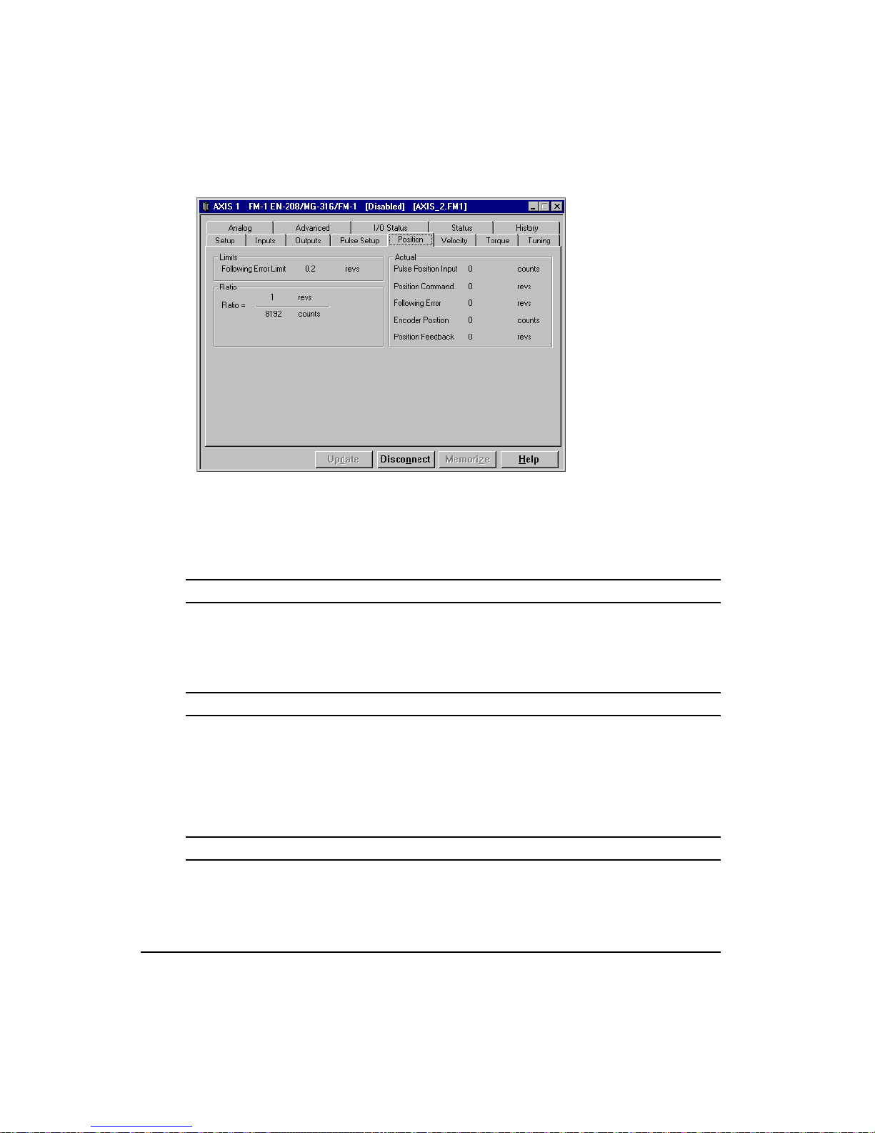
FM-1 Speed Module Reference Manual
Figure 56: Position Tab
All the setups here are effective for all modes used and for both the (Main) Default Operating
Mode and the Alternate Operating Mode.
Limits Group
Following Error Limit
The Following Error is the difference between the Position Command and the Position
Feedback. It is positive when the Position Command is greater than the Position Feedback.
Ratio Group
Ratio
This group of parameters will set up the number of input pulses per motor revolutions
commanded. Maximum effective ratio is 20 counts per motor revolution. The effective ratio
is a signed (+/-) value, which will determine the direction the motor will turn with the defined
direction commands.
Actual Group
Pulse Position Input
This field displays the actual number of pulse input counts received by the pulse input circuit
during the current power up. This value cannot be changed externally and is active at all times
in all modes. The value is signed (+/-) and is only displayed when on line with a drive.
76
Page 93
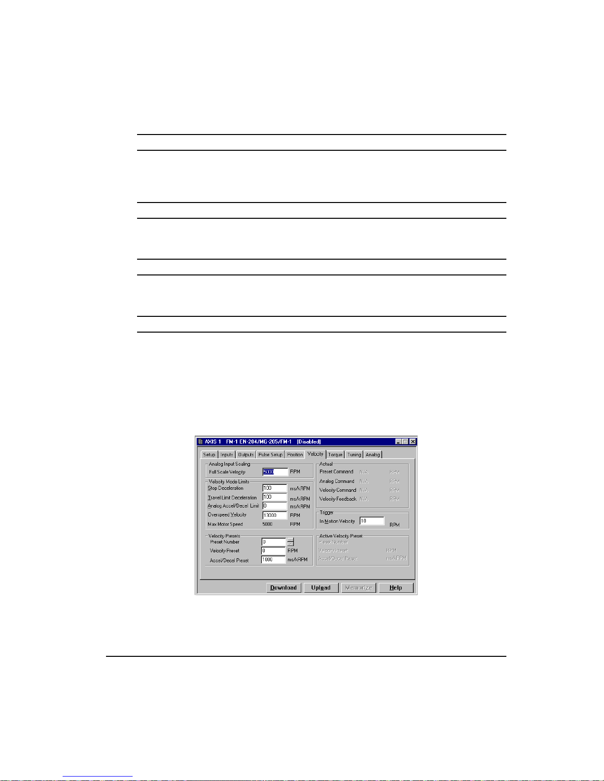
Position Command
This commanded position is generated by the total combination of Velocity and Pulse modes.
The drive forces this value to each Position Feedback when the drive is disabled or in Torque
mode. This is set to zero when the Absolute Position Valid output function is activated.
Following Error
The Following Error is the difference between the Position Command and the Position
Feedback. It is positive when the Position Command is greater than the Position Feedback.
Encoder Position
The motor position in encoder counts since power up when the value was set to zero. This is
a signed 32-bit value and can be set to any value using the serial COM port.
Position Feedback
This is the feedback position of the motor in motor revolutions since power-up when the value
was set to zero.
Velocity Tab
Setting Up Parameters
This tab allows you to set the drive Limits that pertain to velocity mode and, if you are online, view the Actual Velocity mode parameters.
Figure 57: Velocity Tab
77
Page 94

FM-1 Speed Module Reference Manual
All the setups here are effective for all modes used and for both the (Main) Default Operating
Mode and the Alternate Operating Mode.
Analog Input Scaling Group
Full Scale Velocity
The value entered here is used in conjunction with Analog input Full Scale to set up the
Velocity command scaling. The combination of these two parameters will determine the
output velocity (RPM) per volt input commanded.
Velocity Mode Limits Group
Stop Deceleration
The value you enter here defines the rate of velocity change to zero speed when a Stop input
function is activated. The Stop Input Function is effective in all modes including Pulse and
Torque.
The units are ms/kRPM and the range is from 0 to 32700.0. Default is 100 ms/kRPM.
Travel Limit Deceleration
The value you enter here defines the rate of velocity change to zero speed when a Travel Limit
input function is activated. The Travel Limit Input Function is effective in all modes
including Pulse and Torque.
78
The units are ms/kRPM and the range is from 1.0 to 5000.0. Default is 100 ms/kRPM.
Analog Accel/Decel Limit
This parameter determines the maximum accel and decel rate that will be allowed when using
the Analog input in Analog Velocity mode. It does not affect the Stop decel or Travel limit
decel rates.
Overspeed Velocity
When the motor speed exceeds this value, a Motor Overspeed Fault is activated and disables
the drive. This is one of the two parameters that can activate the Motor Overspeed Fault.
The default value is 13000 RPM, which effectively disables the Motor Overspeed detection.
The Overspeed is monitored continuously whether the drive is enabled or not.
Page 95

Setting Up Parameters
Max Motor Speed
This displays the maximum rated motor speed for the selected motor as defined by the motor
specification file. For the User Defined Motors, this is defined in the MOTOR.DDF file.
Actual Group
Preset Command
This Velocity Command is generated by the Velocity Presets. It can be summed with other
commands to make up the final Actual Velocity command, which is sent to the velocity loop
to generate motor motion. It includes the total of Velocity Preset +Velocity Analog
summation if using Summation Mode. Units are RPM.
Analog Command
This is the Velocity command generated by the Analog Input displayed in RPM.
Velocity Command
The Velocity Command is the actual command received by the velocity loop. Units are in
RPMs.
Velocity Feedback
This parameter is the actual feedback motor velocity in RPM.
Trigger Group
In Motion Velocity
This parameter sets the activation point for both the In CW Motion and In CCW Motion
output functions. The output function will deactivate when the motor velocity reaches exactly
half of this value.
Default = 10 RPM
Presets Group
Selected Preset
Displays the currently selected velocity preset number when online with the drive.
79
Page 96

FM-1 Speed Module Reference Manual
Velocity Presets Table
These digital preset velocities can be selected with the digital inputs in a binary pattern. Zero
speed is equivalent to stopping and holding position. Each preset has a ramp associated with
it which is also selected simultaneously with the Preset velocity. The selected ramp is used
whether the drive must accelerate or decelerate to acheive the selected velocity.
Torque Tab
This tab allows you to edit the Torque Limit and view the following torque parameters:
80
Figure 58: Torque Tab
Note
The Torque Limit value takes effect only when the Torque Limit Enable input function is
active.
These parameters are continuously updated when you are online with the drive.
All the setups here are effective for all modes used and for both the (Main) Default Operating
Mode and the Alternate Operating Mode.
Page 97

Setting Up Parameters
Analog Input Scaling Group
Full Scale Torque
The value entered here is used in conjunction with Analog input Full Scale to set up the
Torque command scaling. The combination of these two parameters will determine the output
torque per volt input command.
Actual Group
Torque Command
This parameter returns the torque command value before it is limited. The torque command
may be limited by either the Torque Limit (if the Torque Limit Enable input function is
active) or current foldback.
Torque Limit
This value is the level, which the Torque Command will be limited to when the Torque Limit
input function is active. To make the Torque Limit always active, set the Torque Limit Input
Function to be "Always Active".
Peak Torque Available
This displays the maximum torque available from the selected drive and motor combination.
This is calculated by PowerTools and is not a drive parameter.
Actual Torque Command
Displays the Torque Command after all limiting. This command is used by the current loop
to generate motor torque.
Foldback RMS
This parameter accurately models the thermal heating and cooling of the drive and motor.
When it reaches 100 percent, current foldback will be activated which will limit the torque
available to 80 percent. Foldback will deactivate when the load is reduced and foldback RMS
level drops to 70 percent.
Presets Group
Selected Preset
This displays the currently selected torque preset number when online with the drive.
81
Page 98

FM-1 Speed Module Reference Manual
Torque Presets Table
These digital preset torque values can be selected with the digital inputs in a binary pattern.
Zero torque is roughly equivalent to disabling the drive. The selected Torque preset is used
immediately with no “ramping” to the torque level.
Tuning Tab
All parameters on the Tuning tab are related to the load on the motor and application
requirements.
Load Group
82
Figure 59: Tuning Tab
The load on the motor is specified by two parameters: Inertia Ratio and Friction. Typical
application requirements are specified by the response adjustment and Feedforward Gains.
Position Error Integral is to minimize following error in Pulse follower systems. Notch Filter
is provided to filter machine resonance that is present is some applications.
All the setups here are effective for all modes used and for both the (Main) Default Operating
Mode and the Alternate Operating Mode.
Inertia Ratio
Inertia Ratio specifies the load to rotor inertia ratio and has a range of 0.0 to 50.0. If the exact
inertia is unknown, a conservative approximate value should be used. If you enter an inertia
value higher than the actual inertia, the resultant motor response will tend to be more
oscillatory.
Page 99

Setting Up Parameters
Friction
This parameter is characterized in terms of the rate of friction increase per 100 motor RPM.
If estimated, always use a conservative (less than or equal to actual) estimate. If the friction
is completely unknown, a value of zero should be used. A typical value used here is less than
one percent.
Tuning Group
Response
The Response adjusts the velocity loop bandwidth with a range of 1 to 500 Hertz. In general,
it affects how quickly the drive will respond to commands, load disturbances and velocity
corrections. A good value to start with (the default) is 50 Hz. The maximum value
recommended is 80 Hz.
Position Error Integral Check Box
The Position Error Integral is a control term, which can be used to compensate for the
continuous torque required to hold a vertical load against gravity. It is also useful in Pulse
mode applications to minimize following error.
Time Constant
Position Error Integral is a control term, which can be used in Pulse mode to compensate for
the continuous torque, required to hold a vertical load against gravity or to minimize
following error.
The user configures this control term using the “Position Error Integral Time Constant”
parameter. This parameter determines how quickly the drive will correct for in-position
following error. The time constant is in milliseconds and defines how long it will take to
decrease the following error to 37 percent of the original value. In certain circumstances the
value actually used by the drive will be greater than the value specified here.
Min Time Constant = 1000/Response
For example, with “Response” set to 50, the minimum time constant value is 1000/50 = 20
msec.
Enable Feedforwards Check Box
When feedforwards are enabled, the accuracy of the Inertia and Friction parameters is very
important. If the Inertia parameter is larger than the actual inertia, the result could be a
significant overshoot during ramping. If the Inertia parameter is smaller than the actual
inertia, following error during ramping will be reduced but not eliminated. If the Friction
parameter is greater than the actual friction, it may result in velocity error or instability. If the
83
Page 100

FM-1 Speed Module Reference Manual
Friction parameter is less than the actual friction, velocity error will be reduced but not
eliminated.
Low Pass Filter Group
Low Pass Filter Enable Checkbox
This enables a low pass filter applied to the output of the velocity command before the torque
compensator. The low pass filter is only active in Pulse and Velocity modes, not Torque
Modes.
Low Pass Frequency
This parameter defines the low pass filter cut-off frequency signals exceeding this frequency
will be filtered at a rate of 40 db. per decade.
Analog Tab
This tab is divided into Analog Inputs and Analog Outputs. One analog input is used for
Analog Torque and Velocity modes and two analog outputs are used for diagnostics.
Figure 60: Analog Tab
All the setups here are effective for all modes used and for both the (Main) Default Operating
Mode and the Alternate Operating Mode.
84
 Loading...