

Page 1

INSTRUCTION SHEET
Description
The signal isolator option board provides a means
of isolating both the speed reference, and the start signal
to a non-regenerative drive. Since the circuit common
(or signal common connection) of a typical non-regen
drive is essentially tied directly to the motor A+ terminal,
the user must insure that this connection (or any other
control connection) does not contact Earth ground.
This option when properly installed can help prevent a
drive failure. In applications using a chassis drive (no
enclosure/operators supplied), the operators will most
likely be remotely mounted and thus the possibility of
shorting to earth ground (via vibration or unintentional
connection) exists. T he chassis unit may also be remotely
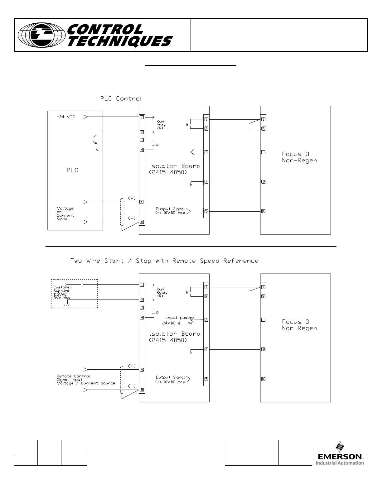
controlled by a PLC or some other form of proces s control,
which is ground referenced. These applications would
typically benefit from using the signal isolator option.
In addition to providing isolation, the option board can
convert a variety of voltage and current signals to a 0 to
10VDC signal for the drive speed reference.
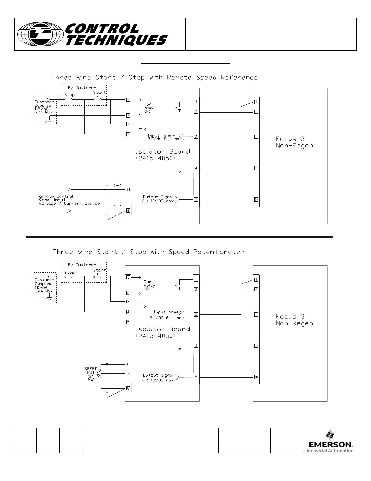
A control relay has been incorporated into the design to
provide a drive start contact. This relay may be configured
for 24VDC or 120VAC operation. The relay can be
controlled by a PLC having either “open emitter” or “open
collector” outputs or it can be s imply set up as a 120VAC
three wire control.
Unlike many currently available reference isolator boards,
the CT Signal Isolator option board can also support a
remote Speed Potentiometer including the power supply
for the potentiometer.
The option has been designed to operate from a single
power supply derived from the drive (or a separate isolated
supply). The range of this supply is 17 to 30VDC with a
current draw of 50ma max.
For further information, consult the Instruction manual
supplied with control. For further assistance contact:
Control Techniques Drives
Technical Support Services
(800)-893-2321
or
(800) 367-8067
Analog Isolator Option Kit
F3NSBD
WARNING
F
AILURE TO DISCONNECT POWER MAY RESULT IN
ELECTRICAL SHOCK
CANNOT BE INADVERTENTLY RESTORED DURING
THE INSTALLATION PROCEDURE
Procedure
Mounting of the signal isolator option PC board can be
done in one of two ways. Using the supplied 5” gray
mounting track and two plastic rivets, the track can be
easily affixed to a panel in the desired location. The option
board can then be snapped into the track and wired.
The second mounting choice is to use the four nylon
standoffs also inc luded in the kit. These adhesive loc king
standoffs provide easy & accessible board mounting
where space is at a premium . As in the inside of a drive
enclosure or cover.
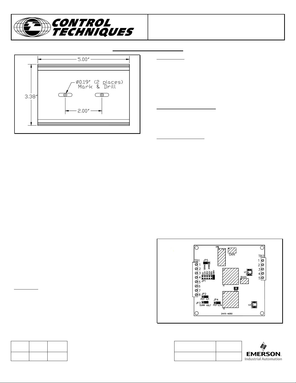
Track Mounting:
1) Locate an area on the panel where the gray mounting
track will fit properly. Mark the centers of the track slots on
the panel per Fig. 2.
. I
NSURE THAT THE POWER
.
Figure 1.
Rev. ECO Date Document No. Page
A 3866 7/02 2415-3050 1 of 6
Page 2
Analog Isolator Option Kit
INSTRUCTION SHEET
F3NSBD
Figure 2.
2) Drill two 0.190” holes. Mount the track in place using
the two supplied nylon push-rivets.
3) Snap the board into the mounting track as desired and
wire the terminals.
Standoff Mounting:
1) Remove the four nylon locking standoffs from the k it.
Snap all four into the four corners of the option PC board
from the solder side.
2) Find a suitable location on the panel or inside the drive
cover or enclosure. Remove the paper covering the
adhesive base of the four standoff s. Square up the bases
and mount down on the panel or cover using sufficient
pressure to set the adhesive.
Terminations & Settings
Signal Isolator wiring options and jumper settings are
described on the next pages. Follow diagrams which
indicate the options and features you desire.
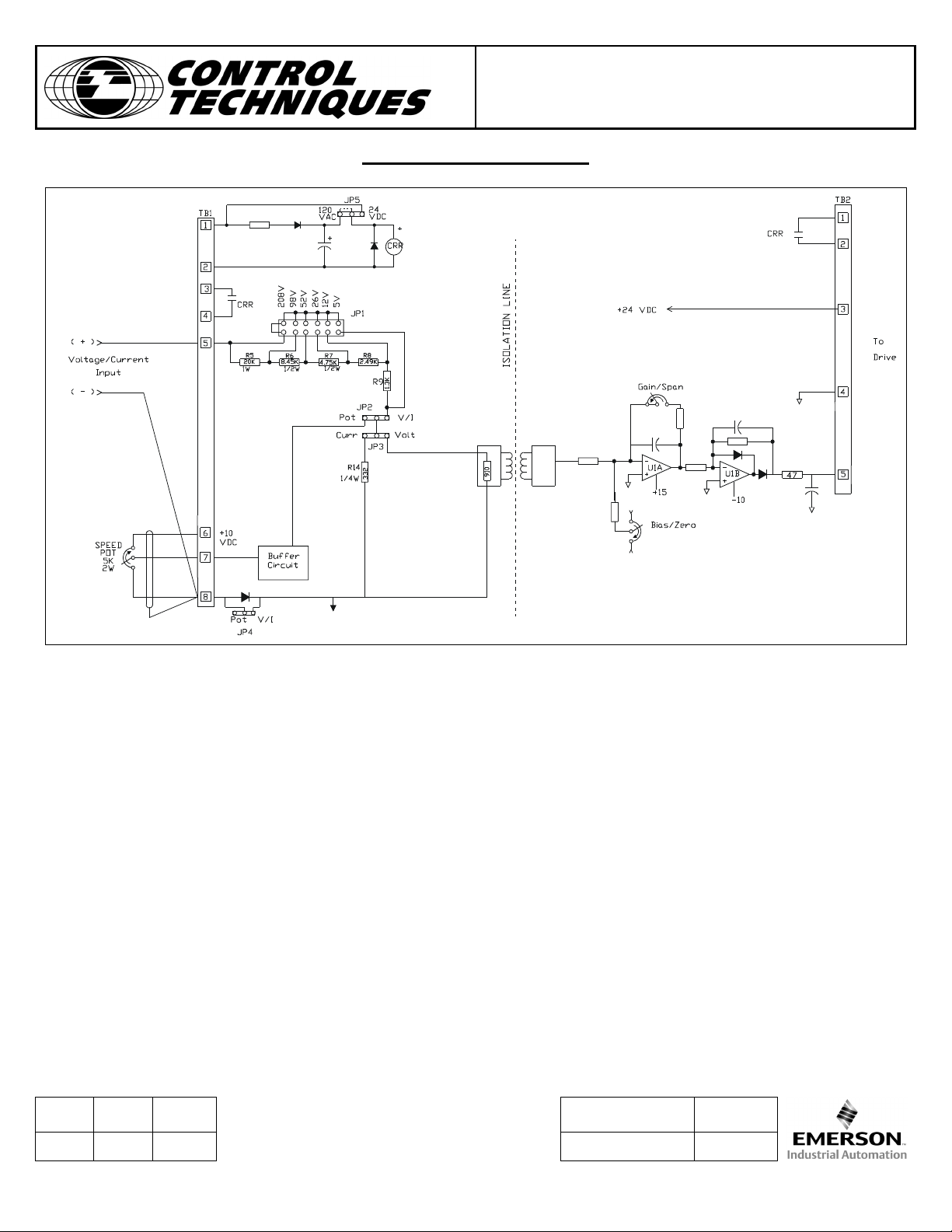
Input (TB1)
1,2 Run relay (TB1-1 positive)
3,4 Normally Open Run Contact
5 Voltage / Current Input
6 + 10VDC Speed Pot Supply (5Kohms Min)
7 Speed Pot or 0 to 10VDC Input (40K Ohms
8 Signal Common
Impedance)
Output (TB2)
1,2 Normally Open Run Contact
3 +24VDC Power Supply Input for Isolator Board
4 Isolated Signal Common to Drive
5 Isolated Speed Reference Output to Drive (0 to
Potentiometer Adjustments:
Gain (Span)
Bias (Zero)
(50ma max.)
+10VDC)
Jumper Programming:
JP1 Selects Input Reference Signal Voltage
Range (5,12,26,52,98 & 208 max.)
JP2 - Speed Potentiometer or External
Voltage/Current Reference Select
(Pot or V/I)
JP3 - Current / Voltage Reference Select
(Curr or Volt)
JP4 - Speed Potentiometer / External
Voltage/Current Reference Select
(Pot or V/I)
JP5 - Control Relay (CRR) Voltage Selection
(24VDC or 120VAC)
Default Jumper Settings
Figure 4.
Rev. ECO Date Document No. Page
A 3866 7/02 2415-3050 2 of 6
Page 3

Analog Isolator Option Kit
F3NSBD
INSTRUCTION SHEET
JUMPER PROGRAMMING TABLE
Input Source Term. Strip Conn. Input JP1 JP2 JP3 JP4
(+) (-) Impedance
Speed Pot* TB1 - 7 TB1 - 8 40K Ohms --- Pot Volt Pot
0 to (+)10VDC TB1 - 7 TB1 - 8 40K Ohms --- Pot Volt V/I
Voltage Ref.
0 to 5 TB1 - 5 TB1 - 8 910 Ohms 5V V/I Volt V/I
0 to 12 2.21K Ohm 12V
0 to 26 4.7K Ohms 26V
0 to 52 9.45K Ohms 52V
0 to 98 17.9K Ohms 98V
0 to 208 37.9K Ohms 208V
Current Input
0-5ma / 1-5 ma TB1 - 5 TB1 - 8 910 Ohms 5V V/I Volt V/I
0-20ma / 4-20ma TB1 - 5 TB1 - 8 243 Ohms 5V V/I Curr V/I
* = +10VDC Supply for speed pot is TB1 - 6
--- = Position doesn’t matter
(+) (-)
(+) (-)
Figure 5.
Specifications
Input Power:
17 - 30 VDC @ 50milliamp Max. Voltage Ranges: 5,12,26,52,98 & 208 VDC
(for control circuitry) Impedance 180 Ohms/Volt
Control Relay (CRR)
24VDC @ 12.1 ma (JP5 = 24VDC) 1-5 milliamps
120VAC @ 20 ma (JP5 = 120VAC) Impedance 910 Ohms
Contact Type/Rating – 2 Form A, 0-20 milliamps
1Amp @ 250VAC 4-20 milliamps
Impedance 250 Ohms
Isolation Voltage:
240VAC Power Systems Speed Pot 5K ohms, 2W
2000VAC Hi-Pot for 1 Minute
Inputs:
Current Ranges: 0-5 milliamps
Output:
Linearity:
0 to (+) 10VDC (Uni-polar)
2%
Rev. ECO Date Document No. Page
A 3866 7/02 2415-3050 3 of 6
Page 4
Analog Isolator Option Kit
INSTRUCTION SHEET
F3NSBD
Set-up Procedure
Voltage Inputs
1. With input voltage sour ce set to zero, adjust the bias
(zero) potentiometer such that the output voltage
(TB2-5 (+) to TB2-4) reads the desired voltage level.
This level may be set to zero, or it may be set to
provide a minimum speed setting for the drive.
2. Set the input voltage source to maximum, adjust the
gain (span) for the m axim um s peed signal to the drive
(+10VDC).
3. Repeat steps 1 and 2 above. Note: Since the bias and
gain potentiometers are interactive, s teps 1 and 2 m ay
have to be performed multiple times.
4. Set-up Complete.
Current Inputs
1. With input current source set to minimum, adjust the
bias (zero) potentiometer such that the output voltage
(TB2-5 (+) to TB2-4) reads the desired voltage level.
This level may be set to zero, or it may be set to
provide a minimum speed setting for the drive.
2. Set the input current source to maximum, adjust the
gain (span) for the maximum speed signal to the drive
(+10VDC).
3. Repeat steps 1 and 2 above. Note: Since the bias and
gain potentiometers are interactive, steps 1 and 2 may
have to be performed multiple times.
4. Set-up Complete
Rev. ECO Date Document No. Page
A 3866 7/02 2415-3050 4 of 6
Page 5
Analog Isolator Option Kit
INSTRUCTION SHEET
F3NSBD
Rev. ECO Date Document No. Page
A 3866 7/02 2415-3050 5 of 6
Page 6
Analog Isolator Option Kit
INSTRUCTION SHEET
F3NSBD
Rev. ECO Date Document No. Page
A 3866 7/02 2415-3050 6 of 6
 Loading...