

Page 1
Focus 3 “M” Contactor
F3M112 & F3M224
Instruction Sheet
APPLICATION
The Focus 3 “M” Contactor Kits are designed for use with the following Focus 3 drives and DB Kits.
Focus 3 Drive “M” Contactor Kit DB Kit
F3N2C, F3N2E, F3M112 25 - 1 HP @ I 20V
F3R2C, or F3R2E (120V)
F3N2C, F3N2E, F3M224 .50 - 2HP @ 240V F3DB224 2HP @ 240V
F3R2C, or F3R2E (240V)
F3N5C, F3N5E, F3M524* 3 - 5HP @ 240V F3DB324 3HP @ 240V
F3R5C, or F3R5E (240V)
*See F3M51S0698 Instruction Sheet
F3DB224 .5HP @ 120V
F3DB1 524 .25 -.33HP @ 120V
F3DB112 75-1HP@ 120V
F3DB1 524 1.5HP @ 240V
F3DB124 .75 - 1HP @ 240V
F3DB0524 .5HP @ 240V
F3DB524 5HP @ 240V
“M” Contactor Kit
Includes a magnetic contactor, interface pc board, and mounting bracket which can be installed
directly on the heatsink of the chassis mount unit and inside the enclosed control. It provides a
positive disconnect of the motor armature when the control is stopped, preventing motor turnover
in case the SCRs should false fire. In addition, an auxiliary form A N.O. contact is included for
customer use. (This kit may be required by local and/or national electrical codes.)
Dynamic Braking Kit
For use with the “M” contactor kits. Dynamic braking provides rapid motor stopping by
automatically connecting a resistor across the armature of the motor to absorb the energy
produced by the coasting motor (now acting as a generator) and bring it to a stop quickly. Note
that the dynamic brake is not a holding (fail-safe) brake. The standard dynamic brake resistors
have been sized for use with DC motors that have no appreciable load inertia connected to the
shaft and have start/stop cycles no more frequent than 3 quick stops with 10 minutes before the
next stop.
REFERENCE
The Focus 3 User Guide should be read in its entirety, paying particular attention to the Warnings
and Cautions in each section before installing, starting, or maintaining these drives.
ITEMS INCLUDED IN “M” CONTACTOR KIT
1- bracket assembly with driver board and “MC” motor contactor (unassembled)
2- mounting screws for use with the bracket assembly
1- adhesive strip used in mounting the bracket
- wires used to connect the contactor kit and the drive (only eight wires will be used in a
12
single application).
P/N *2415-3513 Rev. A1 1 of 7
F3M2IS0401
Page 2
“M” Contactor Kit
INSTALLATION OF “M” CONTACTOR
CAUTION!
Improper procedures can result in personal injury or equipment damage. Only qualified electrical
maintenance technicians familiar with electronic drives and their standard safety precautions
should be permitted to install, start-up, or maintain this apparatus.
NOTE
Instructions for the installation of the “M” contactor kit are divided into two sections because the
non-regen and regen drives require different wiring connections between the contactor kit and the
drive. In each section, the wiring connections are shown in the table while the other assembly
steps are listed below.
1. Remove drive control board:
Remove the two mounting screws securing the board.
Push the retaining tabs on the two nylon standoffs to free the board.
Lift board up and out of the way.
Do not remove any wires from the control board.
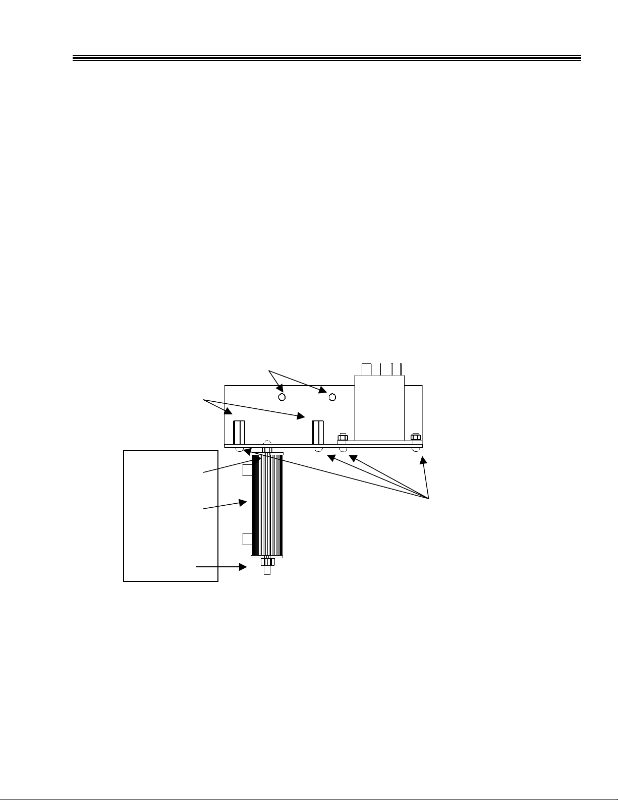
2. Pre-assemble components as shown in figure A below.
3. Mount bracket assembly as shown in figure B below using the two 8-32 x 3/8 machine screws
provided in the kit (use adhesive strip supplied if heat sink does not have threaded holes).
4. Install driver board onto hex standoffs using two 6-32 x 3/8 machine screws as shown in figure B with
orientation as shown in figure C.
6-32x5/8
Hex Stand-off
Internal Tooth
lock washer and
8-32 Hex nut
DB Kit if Used
Lock
washer
and 8-32
Mounting Holes
F3N2C and F3N2E
Figure A
6-32 x 3/8 machine
screw with Hex nut
and lockwasher
2 of 7
Page 3
“M” Contactor Kit
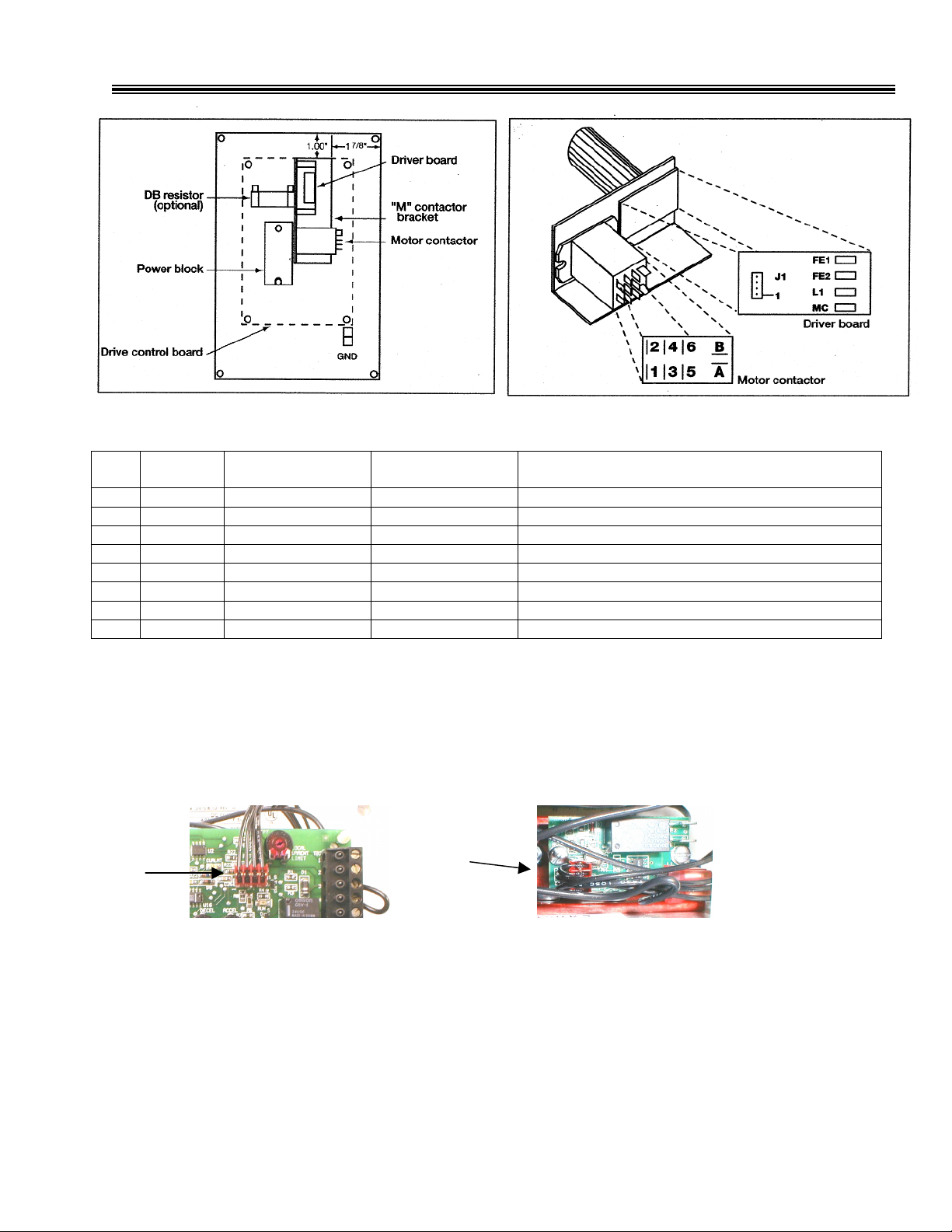
Figure B Figure C
Locate the wires listed below (KIT WIRE) and connect the respective ends as indicated in the table below. Refer to
figures B, C & D.
Step # Kit Wire Term – Location Term – Location Notes
5 A & MC A – motor contactor MC – driver board
6 L1 & 1L1 L1 – driver board 1L1 - control board
7 B & 1L2 B – motor contactor 1L2 - control board
8 6 & A+ 6 – motor contactor A+ - control board
9 4 & X 4 – motor contactor X - control board
10 5 & A- 5 – motor contactor A- - control board
11 3 & F- 3 – motor contactor F- - control board
12 J1 & JP1 J1 – driver board See step#14
* see figure E
13.Replace drive control board:
Use caution to not pinch any wiring.
Secure the board below the retaining tabs on the two nylon standoffs.
Tighten the two mounting screws.
14. Connect the remaining end of wire “J1 & JP1” to the JP1 connector on the control board. Insure that
pin #1 of J1 connects to pin #1 of JP1.
JP1 J1
15. Remove and discard factory installed jumper straps located on TB1 of drive control board:
jumper connecting terminals “F-” and “A-” and the jumper connecting terminals “A+” and “X”.
(see figure D below)
16. Installation complete:
Replace cover if necessary and test operation.
The auxiliary form A N.O. contact (terminals FEl and FE2) is located on the driver board
(see figure C).
Route wire under control pcb & up left side to 1L1 *
Route wire under control pcb & up left side to 1L2 *
Route wire over control pcb & down right side to MC by T1 *
Route wire over control pcb & down right side to MC by T1 *
Route wire over control pcb & down right side to MC by T1 *
Route wire over control pcb & down right side to MC by T1 *
Route wire under control pcb & down top side to the driver bd
3 of 7
Page 4

“M” Contactor Kit
1L1
1L2
F-
A-, A+ & X
Jumper Straps
Figure D
Step #6 & #7
Steps 8,9,10 &11
Figure E
4 of 7
Page 5

“M” Contactor Kit
F3R2C and F3R2E
1. Remove drive control board:
Remove the two mounting screws securing the board. Push the retaining tabs on the two nylon
standoffs to free the board.
Remove wires from terminals “1 FEl” and “1 L2” on drive control board.
Swing board up and out of the way.
2. Pre-assemble components as shown in figure A on page 2.
3. Mount bracket assembly as shown in figure E below using the two 8-32 x ½ machine screws provided
in the kit (use adhesive strip supplied if heat sink does not have threaded holes).
4. Install driver board onto hex standoffs using two 6-32 x 3/8 machine screws as shown in figure E with
orientation as shown in figure F.
Locate the wires listed below (KIT WIRE) and connect the respective ends as indicated in the table
below. Refer to figures E, F & G.
Step # Kit Wire Term – Location Term – Location Notes
Figure F Figure E
5 A & MC A – motor contactor MC – driver board
6 L1 & 1FU L1 – driver board 1FU
7 B & 2FU B – motor contactor 2FU
8 6 & A+ 6 – motor contactor TB1 A+
9 4 & A+ 4 – motor contactor A+
10 5 & A- 5 – motor contactor A-
11 3 & A- 3 – motor contactor A2
12 J1 & JP1 J1 – driver board See step #14
Fuse 1FU
Fuse 2FU
TB1 terminal block see note #1
Control board
TB1 terminal block see note #2
Power block
Route wire under control pcb & down top side to the driver bd
Note #1 Cut off faston terminal at wire end marked A+ and strip off 1/4” insulation from the wire.
Remove and discard existing wires from terminal A+ on the drive control board and
terminal TB1- A+.
Note #2 Cut off faston terminal at wire end marked A- and strip off 1/4” insulation from the wire.
Remove and discard existing wires from power block terminal A2 and terminal TB1 -A-.
5 of 7
Page 6

A+
“M” Contactor Kit
13. Replace drive control board:
Use caution to not pinch any wiring.
Secure the board below the retaining tabs on the two nylon standoffs.
Tighten the two mounting screws.
Reconnect wires to terminals “1FE1” and “1L2” on the drive control board (see figure G).
14. Connect the remaining end of wire “J1 & JP1” to the JP1 connector on the control board. Insure that
pin #1 of J1 connects to pin #1 of JP1. (Note: On this model, its is easier to connect wire marked #1
to pin #4 on both (male) connectors).
15. Installation complete:
Replace cover if necessary and test operation. The auxiliary form A N.O. contact (terminals FEl and FE2) is located on the driver board
(see figure F).
Figure G
4 3 2 1
JP1
1FE1
1L2
6 of 7
Page 7

“M” Contactor Kit
Figure H
Step #5
Step #7
Step #6
Step #10
Step #11
Figure I
Step #8
Step #9
Step #6
Step #5
Step #7
7 of 7
Step #12
 Loading...