

Page 1

Epsilon EP-P Drive and
FM-3/4 Modules
Reference Manual
P/N 400518-04
Revision: A1
Date: December 22, 2006
© Control Techniques Americas LLC, 2006
Page 2

Page 3

Epsilon EP-P Drive and FM-3/4 Module
Reference Manual
Information furnished by Control Techniques Americas LLC (Control Techniques) is believed to be accurate and reliable. However,
no responsibility is assumed by Control Techniques for its use. Control Techniques reserves the right to change the design or
operation of the equipment described herein and any associated motion products without notice. Control Techniques also assumes
no responsibility for any errors that may appear in this document. Information in this document is subject to change without notice.
P/N 400518-04
Revision: A1
Date: December 22, 2006
© Control Techniques Americas LLC, 2006
Page 4

© Control Techniques Americas LLC, 2006 All rights reserved.
Part Number: 400518-04
Revision: A1
Date: December 2006
Printed in United States of America
Information in this document is subject to change without notice. No part of this document may be reproduced or transmitted in any
form or by any means, electronic or mechanical, for any purpose, without the express written permission of Control Techniques.
The following are trademarks of Control Techniques and may not be reproduced in any fashion without written approval of Control
Techniques: EMERSON Motion Control,
EMERSON Motion Control PowerTools, AXIMA, “Motion Made Easy.”
Control Techniques is a division of EMERSON Co.
Control Techniques, Inc. is not affiliated with Microsoft Corporation, owner of the Microsoft, Windows, and Windows NT
trademarks.
This document has been prepared to conform to the current released version of the product. Because of our extensive development
efforts and our desire to further improve and enhance the product, inconsistencies may exist between the product and documentation
in some instances. Call your customer support representative if you encounter an inconsistency.
ii
Page 5

Customer Support
Control Techniques Americas LLC
12005 Technology Drive
Eden Prairie, Minnesota 55344-3620
U.S.A.
Telephone: (952) 995-8000 or (800) 893-2321
It is Control Techniques’ goal to ensure your greatest possible satisfaction with the operation of our products. We are
dedicated to providing fast, friendly, and accurate assistance. That is why we offer you so many ways to get the support you
need. Whether it’s by phone, fax or modem, you can access Control Techniques support information 24 hours a day, seven
days a week. Our wide range of services include:
FAX (952) 995-8099
You can FAX questions and comments to Control Techniques. Just send a FAX to the number listed above.
Website and Email www.emersonct.com
Website: www.emersonct.com
Email: info@emersonct.com
If you have Internet capabilities, you also have access to technical support using our website. The website includes technical
notes, frequently asked questions, release notes and other technical documentation. This direct technical support connection
lets you request assistance and exchange software files electronically.
Technical Support (952) 995-8033 or (800) 893-2321
Email: service@emersonct.com
Control Techniques’ “Motion Made Easy” products are backed by a team of professionals who will service your installation.
Our technical support center in Eden Prairie, Minnesota is ready to help you solve those occasional problems over the
telephone. Our technical support center is available 24 hours a day for emergency service to help speed any problem solving.
Also, all hardware replacement parts, if needed, are available through our customer service organization.
When you call, please be at your computer, with your documentation easily available, and be prepared to provide the
following information:
• Product version number, found by choosing About from the Help menu
• The type of controller or product you are using
• Exact wording of any messages that appear on your screen
• What you were doing when the problem occurred
• How you tried to solve the problem
Need on-site help? Control Techniques provides service, in most cases, the next day. Just call Control Techniques’ technical
support center when on-site service or maintenance is required.
Training Services (952) 995-8000 or (800) 893-2321
Email: training@emersonct.com
Control Techniques maintains a highly trained staff of instructors to familiarize customers with Control Techniques’ “Motion
Made Easy” products and their applications. A number of courses are offered, many of which can be taught in your plant upon
request.
Application Engineering (952) 995-8000 or (800) 893-2321
Email: service@emersonct.com
An experienced staff of factory application engineers provides complete customer support for tough or complex applications.
Our engineers offer you a broad base of experience and knowledge of electronic motion control applications.
iii
Page 6

Customer Service (Sales) (952) 995-8000 or (800) 893-2321
Email: customer.service@emersonct.com
Authorized Control Techniques distributors may place orders directly with our Customer Service department. Contact the
Customer Service department at this number for the distributor nearest you.
Document Conventions
Manual conventions have been established to help you learn to use this manual quickly and easily. As much as possible, these
conventions correspond to those found in other Microsoft® Windows® compatible software documentation.
Menu names and options are printed in bold type: the File menu.
Dialog box names begin with uppercase letters: the Axis Limits dialog box.
Dialog box field names are in quotes: “Field Name.”
Button names are in italic: OK button.
Source code is printed in Courier font: Case ERMS.
In addition, you will find the following typographic conventions throughout this manual.
This Represents
bold
italic
ALL CAPITALS Directory names, file names, key names, and acronyms.
SMALL CAPS Non-printable ASCII control characters.
KEY1+KEY2
example: (Alt+F)
KEY1,KEY2
example: (Alt,F)
Characters that you must type exactly as they appear. For example, if you are directed to type
a:setup, you should type all the bold characters exactly as they are printed.
Placeholders for information you must provide. For example, if you are directed to type
filename, you should type the actual name for a file instead of the word shown in italic type.
A plus sign (+) between key names means to press and hold down the first key while you press
the second key.
A comma (,) between key names means to press and release the keys one after the other.
Note
For the purpose of this manual and product, “Note” indicates essential information about the product or the respective part
of the manual.
“Warning” indicates a potentially hazardous situation that, if not avoided, could result in death or serious injury.
“Caution” indicates a potentially hazardous situation that, if not avoided, may result in minor or moderate injury.
“Caution” used without the safety alert symbol indicates a potentially hazardous situation that, if not avoided, may result
in property damage.
Throughout this manual, the word "module" refers to an FM-3/4 module, the word “base drive” refers to an MDS Drive
Module or an EN drive, the word "drive" refers to an Epsilon EP-P drive, and the word "device" refers to an FM-3/4 module
and/or an Epsilon EP-P drive.
iv
Page 7

Safety Instructions
General Warning
Failure to follow safe installation guidelines can cause death or serious injury. The voltages used in the product can cause
severe electric shock and/or burns and could be lethal. Extreme care is necessary at all times when working with or adjacent
to the product. The installation must comply with all relevant safety legislation in the country of use.
Qualified Person
For the purpose of this manual and product, a “qualified person” is one who is familiar with the installation, construction and
operation of the equipment and the hazards involved. In addition, this individual has the following qualifications:
• Is trained and authorized to energize, de-energize, clear and ground and tag circuits and equipment in accordance with
established safety practices.
• Is trained in the proper care and use of protective equipment in accordance with established safety practices.
• Is trained in rendering first aid.
Reference Materials
The following related reference and installation manuals may be useful with your particular system.
• Function Module Installation Manual (P/N 400506-03)
• Modular Drive System (MDS) Reference Manual (P/N 400525-01)
• FM-3 and FM-4 Connectivity Reference Manual (P/N 400508-04)
• Epsilon EP Installation Manual (P/N 400518-01)
v
Page 8

vi
Page 9

Safety Precautions
This product is intended for professional integration into a complete system. If you install the product incorrectly, it may
present a safety hazard. The product and system may use high voltages and currents, carry a high level of stored electrical
energy, or control mechanical equipment that can cause injury.
You should give close attention to the electrical installation and system design to avoid hazards either in normal operation or
in the event of equipment malfunction. System design, installation, commissioning and maintenance must be carried out by
personnel who have the necessary training and experience. Read and follow this safety information and the instruction manual
carefully.
Enclosure
This product is intended to be mounted in an enclosure which prevents access except by trained and authorized personnel,
and which prevents the ingress of contamination. This product is designed for use in an environment classified as pollution
degree 2 in accordance with IEC664-1. This means that only dry, non-conducting contamination is acceptable.
Setup, Commissioning and Maintenance
It is essential that you give careful consideration to changes to drive settings. Depending on the application, a change could
have an impact on safety. You must take appropriate precautions against inadvertent changes or tampering. Restoring default
parameters in certain applications may cause unpredictable or hazardous operation.
Safety of Machinery
Within the European Union all machinery with which this product is used must comp ly with Directive 89/392/EEC, Safety
of Machinery.
The product has been designed and tested to a high standard, and failures are very unlikely. However the level of integrity
offered by the product’s control function – for example stop/start, forward/reverse and maximum speed – is not sufficient for
use in safety-critical applications without additional independent channels of protection. All applications where malfunction
could cause injury or loss of life must be subject to a risk assessment, and further protection provided where needed.
Safety Considerations
General warning
Failure to follow safe installation guidelines can cause death or serious injury. The voltages used in thi s un it can cause seve re el ectric
shock and/or burns, and could be lethal. Extreme care is necessary at all times when working with or adj ac ent to this equipment. The
installation must comply with all relevant safety legislation in the country of use.
AC supply isolation device
The AC supply must be removed from the drive using an approved isolation device or disconnect before any servicing work is
performed, other than adjustments to the settings or parameters spec ified in the manual. The drive contains capacitors which remain
charged to a potentially lethal voltage after the supply has been removed. Allow at least 3 minutes after removing the supply before
carrying out any work which may involve contact with electrical connections to the drive.
Products connected by plug and socket
A special hazard may exist where the drive is incorporated into a product which is connected to the AC supply by a plug and socket.
When unplugged, the pins of the plug may be connected to the drive input, which is only separated from the charge stored in the bus
capacitor by semiconductor devices. To avoid any possibility of electric shock from the pins, if they are accessible, a means must be
provided for automatically disconnecting the plug from the drive (that is, a latching contactor).
Grounding (Earthing, equipotential bonding)
The drive must be grounded by a conductor sufficient to carry all possible fault current in the event of a fault. The ground connections
shown in the manual must be followed.
Fuses
Fuses or over-current protection must be provided at the input in accordance with the instructions in the manual.
Isolation of control circuits
The installer must ensure that the external c ontrol c ircuits ar e isolated f rom human contact by at le ast one layer of insula tio n rated for
use at the applied AC supply voltage.
vii
Page 10

viii
Page 11

Table of Contents
Customer Support . . . . . . . . . . . . . . . . . . . . . . . . . . . . . . . . . . . . . . . . . . . . . . . . . . . . . . . . . . . . . . . . . . . . . . . . . . . . . . . . . . iii
Document Conventions . . . . . . . . . . . . . . . . . . . . . . . . . . . . . . . . . . . . . . . . . . . . . . . . . . . . . . . . . . . . . . . . . . . . . . . . . . . . . . iv
Safety Instructions. . . . . . . . . . . . . . . . . . . . . . . . . . . . . . . . . . . . . . . . . . . . . . . . . . . . . . . . . . . . . . . . . . . . . . . . . . . . . . . . . . .v
Reference Materials. . . . . . . . . . . . . . . . . . . . . . . . . . . . . . . . . . . . . . . . . . . . . . . . . . . . . . . . . . . . . . . . . . . . . . . . . . . . . . . . . .v
Safety Considerations vii
Introduction 1
Epsilon EP Drive . . . . . . . . . . . . . . . . . . . . . . . . . . . . . . . . . . . . . . . . . . . . . . . . . . . . . . . . . . . . . . . . . . . . . . . . . . . . . . . . . . . .1
FM-3 and FM-4 . . . . . . . . . . . . . . . . . . . . . . . . . . . . . . . . . . . . . . . . . . . . . . . . . . . . . . . . . . . . . . . . . . . . . . . . . . . . . . . . . . . . .1
Operational Overview 3
Software Interface . . . . . . . . . . . . . . . . . . . . . . . . . . . . . . . . . . . . . . . . . . . . . . . . . . . . . . . . . . . . . . . . . . . . . . . . . . . . . . . . . . .3
PowerTools Pro Setup Software . . . . . . . . . . . . . . . . . . . . . . . . . . . . . . . . . . . . . . . . . . . . . . . . . . . . . . . . . . . . . . . . . . . . . . . .3
Keypad Interface of the FM-3/4 Module. . . . . . . . . . . . . . . . . . . . . . . . . . . . . . . . . . . . . . . . . . . . . . . . . . . . . . . . . . . . . . . . . .4
How Motion Works. . . . . . . . . . . . . . . . . . . . . . . . . . . . . . . . . . . . . . . . . . . . . . . . . . . . . . . . . . . . . . . . . . . . . . . . . . . . . . . . . .6
How Jogging Works . . . . . . . . . . . . . . . . . . . . . . . . . . . . . . . . . . . . . . . . . . . . . . . . . . . . . . . . . . . . . . . . . . . . . . . . . . . . . . . . .6
How Home Works. . . . . . . . . . . . . . . . . . . . . . . . . . . . . . . . . . . . . . . . . . . . . . . . . . . . . . . . . . . . . . . . . . . . . . . . . . . . . . . . . . .6
How Indexes Work . . . . . . . . . . . . . . . . . . . . . . . . . . . . . . . . . . . . . . . . . . . . . . . . . . . . . . . . . . . . . . . . . . . . . . . . . . . . . . . . .13
How Communications Work. . . . . . . . . . . . . . . . . . . . . . . . . . . . . . . . . . . . . . . . . . . . . . . . . . . . . . . . . . . . . . . . . . . . . . . . . .17
Brake Operation. . . . . . . . . . . . . . . . . . . . . . . . . . . . . . . . . . . . . . . . . . . . . . . . . . . . . . . . . . . . . . . . . . . . . . . . . . . . . . . . . . . .24
How Data Capture Works . . . . . . . . . . . . . . . . . . . . . . . . . . . . . . . . . . . . . . . . . . . . . . . . . . . . . . . . . . . . . . . . . . . . . . . . . . . . 25
Setting Up Parameters 27
Graph View . . . . . . . . . . . . . . . . . . . . . . . . . . . . . . . . . . . . . . . . . . . . . . . . . . . . . . . . . . . . . . . . . . . . . . . . . . . . . . . . . . . . . . .27
Setup View. . . . . . . . . . . . . . . . . . . . . . . . . . . . . . . . . . . . . . . . . . . . . . . . . . . . . . . . . . . . . . . . . . . . . . . . . . . . . . . . . . . . . . . .29
Status Online Tab (Online Only). . . . . . . . . . . . . . . . . . . . . . . . . . . . . . . . . . . . . . . . . . . . . . . . . . . . . . . . . . . . . . . . . . . . . . .31
Information Tab (Online Only) . . . . . . . . . . . . . . . . . . . . . . . . . . . . . . . . . . . . . . . . . . . . . . . . . . . . . . . . . . . . . . . . . . . . . . . .33
Motor View . . . . . . . . . . . . . . . . . . . . . . . . . . . . . . . . . . . . . . . . . . . . . . . . . . . . . . . . . . . . . . . . . . . . . . . . . . . . . . . . . . . . . . .33
User Units View . . . . . . . . . . . . . . . . . . . . . . . . . . . . . . . . . . . . . . . . . . . . . . . . . . . . . . . . . . . . . . . . . . . . . . . . . . . . . . . . . . .40
Master Units View. . . . . . . . . . . . . . . . . . . . . . . . . . . . . . . . . . . . . . . . . . . . . . . . . . . . . . . . . . . . . . . . . . . . . . . . . . . . . . . . . .42
Position View. . . . . . . . . . . . . . . . . . . . . . . . . . . . . . . . . . . . . . . . . . . . . . . . . . . . . . . . . . . . . . . . . . . . . . . . . . . . . . . . . . . . . .45
Velocity View . . . . . . . . . . . . . . . . . . . . . . . . . . . . . . . . . . . . . . . . . . . . . . . . . . . . . . . . . . . . . . . . . . . . . . . . . . . . . . . . . . . . .48
Ramps View. . . . . . . . . . . . . . . . . . . . . . . . . . . . . . . . . . . . . . . . . . . . . . . . . . . . . . . . . . . . . . . . . . . . . . . . . . . . . . . . . . . . . . .49
Torque View . . . . . . . . . . . . . . . . . . . . . . . . . . . . . . . . . . . . . . . . . . . . . . . . . . . . . . . . . . . . . . . . . . . . . . . . . . . . . . . . . . . . . .52
Tuning View . . . . . . . . . . . . . . . . . . . . . . . . . . . . . . . . . . . . . . . . . . . . . . . . . . . . . . . . . . . . . . . . . . . . . . . . . . . . . . . . . . . . . .53
Faults View . . . . . . . . . . . . . . . . . . . . . . . . . . . . . . . . . . . . . . . . . . . . . . . . . . . . . . . . . . . . . . . . . . . . . . . . . . . . . . . . . . . . . . .54
PLS View. . . . . . . . . . . . . . . . . . . . . . . . . . . . . . . . . . . . . . . . . . . . . . . . . . . . . . . . . . . . . . . . . . . . . . . . . . . . . . . . . . . . . . . . .58
Setup NVM View . . . . . . . . . . . . . . . . . . . . . . . . . . . . . . . . . . . . . . . . . . . . . . . . . . . . . . . . . . . . . . . . . . . . . . . . . . . . . . . . . .60
Capture View. . . . . . . . . . . . . . . . . . . . . . . . . . . . . . . . . . . . . . . . . . . . . . . . . . . . . . . . . . . . . . . . . . . . . . . . . . . . . . . . . . . . . .61
Queues View . . . . . . . . . . . . . . . . . . . . . . . . . . . . . . . . . . . . . . . . . . . . . . . . . . . . . . . . . . . . . . . . . . . . . . . . . . . . . . . . . . . . . .64
User Variables View . . . . . . . . . . . . . . . . . . . . . . . . . . . . . . . . . . . . . . . . . . . . . . . . . . . . . . . . . . . . . . . . . . . . . . . . . . . . . . . .66
User Bits View. . . . . . . . . . . . . . . . . . . . . . . . . . . . . . . . . . . . . . . . . . . . . . . . . . . . . . . . . . . . . . . . . . . . . . . . . . . . . . . . . . . . .67
I/O Setup Group. . . . . . . . . . . . . . . . . . . . . . . . . . . . . . . . . . . . . . . . . . . . . . . . . . . . . . . . . . . . . . . . . . . . . . . . . . . . . . . . . . . .70
Assignments. . . . . . . . . . . . . . . . . . . . . . . . . . . . . . . . . . . . . . . . . . . . . . . . . . . . . . . . . . . . . . . . . . . . . . . . . . . . . . . . . . . . . . .70
Assignments View. . . . . . . . . . . . . . . . . . . . . . . . . . . . . . . . . . . . . . . . . . . . . . . . . . . . . . . . . . . . . . . . . . . . . . . . . . . . . . . . . .71
Selector View. . . . . . . . . . . . . . . . . . . . . . . . . . . . . . . . . . . . . . . . . . . . . . . . . . . . . . . . . . . . . . . . . . . . . . . . . . . . . . . . . . . . . .74
Input Lines View . . . . . . . . . . . . . . . . . . . . . . . . . . . . . . . . . . . . . . . . . . . . . . . . . . . . . . . . . . . . . . . . . . . . . . . . . . . . . . . . . . .76
Output Lines View. . . . . . . . . . . . . . . . . . . . . . . . . . . . . . . . . . . . . . . . . . . . . . . . . . . . . . . . . . . . . . . . . . . . . . . . . . . . . . . . . .77
Analog Inputs View. . . . . . . . . . . . . . . . . . . . . . . . . . . . . . . . . . . . . . . . . . . . . . . . . . . . . . . . . . . . . . . . . . . . . . . . . . . . . . . . .77
Analog Outputs View . . . . . . . . . . . . . . . . . . . . . . . . . . . . . . . . . . . . . . . . . . . . . . . . . . . . . . . . . . . . . . . . . . . . . . . . . . . . . . .79
ix
Page 12

Motion Group . . . . . . . . . . . . . . . . . . . . . . . . . . . . . . . . . . . . . . . . . . . . . . . . . . . . . . . . . . . . . . . . . . . . . . . . . . . . . . . . . . . . .81
Home View . . . . . . . . . . . . . . . . . . . . . . . . . . . . . . . . . . . . . . . . . . . . . . . . . . . . . . . . . . . . . . . . . . . . . . . . . . . . . . . . . . . . . . .84
Index View . . . . . . . . . . . . . . . . . . . . . . . . . . . . . . . . . . . . . . . . . . . . . . . . . . . . . . . . . . . . . . . . . . . . . . . . . . . . . . . . . . . . . . .87
Gearing View . . . . . . . . . . . . . . . . . . . . . . . . . . . . . . . . . . . . . . . . . . . . . . . . . . . . . . . . . . . . . . . . . . . . . . . . . . . . . . . . . . . . .94
Stopping Motion . . . . . . . . . . . . . . . . . . . . . . . . . . . . . . . . . . . . . . . . . . . . . . . . . . . . . . . . . . . . . . . . . . . . . . . . . . . . . . . . . . .97
Network Group . . . . . . . . . . . . . . . . . . . . . . . . . . . . . . . . . . . . . . . . . . . . . . . . . . . . . . . . . . . . . . . . . . . . . . . . . . . . . . . . . . . .98
Modbus View . . . . . . . . . . . . . . . . . . . . . . . . . . . . . . . . . . . . . . . . . . . . . . . . . . . . . . . . . . . . . . . . . . . . . . . . . . . . . . . . . . . . .98
DeviceNet View . . . . . . . . . . . . . . . . . . . . . . . . . . . . . . . . . . . . . . . . . . . . . . . . . . . . . . . . . . . . . . . . . . . . . . . . . . . . . . . . . . 100
Profibus View . . . . . . . . . . . . . . . . . . . . . . . . . . . . . . . . . . . . . . . . . . . . . . . . . . . . . . . . . . . . . . . . . . . . . . . . . . . . . . . . . . . .100
Ethernet View . . . . . . . . . . . . . . . . . . . . . . . . . . . . . . . . . . . . . . . . . . . . . . . . . . . . . . . . . . . . . . . . . . . . . . . . . . . . . . . . . . . .100
Programming 101
Programs . . . . . . . . . . . . . . . . . . . . . . . . . . . . . . . . . . . . . . . . . . . . . . . . . . . . . . . . . . . . . . . . . . . . . . . . . . . . . . . . . . . . . . . .1 03
Program Instruction Types . . . . . . . . . . . . . . . . . . . . . . . . . . . . . . . . . . . . . . . . . . . . . . . . . . . . . . . . . . . . . . . . . . . . . . . . . .103
Adding and Deleting Programs. . . . . . . . . . . . . . . . . . . . . . . . . . . . . . . . . . . . . . . . . . . . . . . . . . . . . . . . . . . . . . . . . . . . . . .115
Program Multi-Tasking. . . . . . . . . . . . . . . . . . . . . . . . . . . . . . . . . . . . . . . . . . . . . . . . . . . . . . . . . . . . . . . . . . . . . . . . . . . . .117
Example Programs . . . . . . . . . . . . . . . . . . . . . . . . . . . . . . . . . . . . . . . . . . . . . . . . . . . . . . . . . . . . . . . . . . . . . . . . . . . . . . . .120
Parameter Descriptions 127
Quick Start for an FM-4 Module 161
Basic Setup Steps . . . . . . . . . . . . . . . . . . . . . . . . . . . . . . . . . . . . . . . . . . . . . . . . . . . . . . . . . . . . . . . . . . . . . . . . . . . . . . . . .1 61
Example Application Start Up . . . . . . . . . . . . . . . . . . . . . . . . . . . . . . . . . . . . . . . . . . . . . . . . . . . . . . . . . . . . . . . . . . . . . . .172
Tuning Procedures 179
PID vs. State-Space. . . . . . . . . . . . . . . . . . . . . . . . . . . . . . . . . . . . . . . . . . . . . . . . . . . . . . . . . . . . . . . . . . . . . . . . . . . . . . . .179
Tuning Procedure . . . . . . . . . . . . . . . . . . . . . . . . . . . . . . . . . . . . . . . . . . . . . . . . . . . . . . . . . . . . . . . . . . . . . . . . . . . . . . . . .179
Tuning Parameters. . . . . . . . . . . . . . . . . . . . . . . . . . . . . . . . . . . . . . . . . . . . . . . . . . . . . . . . . . . . . . . . . . . . . . . . . . . . . . . . .182
Determining Tuning Parameter Values. . . . . . . . . . . . . . . . . . . . . . . . . . . . . . . . . . . . . . . . . . . . . . . . . . . . . . . . . . . . . . . . .183
Diagnostics and Troubleshooting 189
Diagnostic Display . . . . . . . . . . . . . . . . . . . . . . . . . . . . . . . . . . . . . . . . . . . . . . . . . . . . . . . . . . . . . . . . . . . . . . . . . . . . . . . .189
Drive Faults. . . . . . . . . . . . . . . . . . . . . . . . . . . . . . . . . . . . . . . . . . . . . . . . . . . . . . . . . . . . . . . . . . . . . . . . . . . . . . . . . . . . . .194
Error Messages . . . . . . . . . . . . . . . . . . . . . . . . . . . . . . . . . . . . . . . . . . . . . . . . . . . . . . . . . . . . . . . . . . . . . . . . . . . . . . . . . . .194
Online Status Indicators . . . . . . . . . . . . . . . . . . . . . . . . . . . . . . . . . . . . . . . . . . . . . . . . . . . . . . . . . . . . . . . . . . . . . . . . . . . .197
Diagnostic Analog Output Test Points . . . . . . . . . . . . . . . . . . . . . . . . . . . . . . . . . . . . . . . . . . . . . . . . . . . . . . . . . . . . . . . . . 200
Specifications 201
Dimensions and Clearances . . . . . . . . . . . . . . . . . . . . . . . . . . . . . . . . . . . . . . . . . . . . . . . . . . . . . . . . . . . . . . . . . . . . . . . . .201
Cable Diagrams. . . . . . . . . . . . . . . . . . . . . . . . . . . . . . . . . . . . . . . . . . . . . . . . . . . . . . . . . . . . . . . . . . . . . . . . . . . . . . . . . . .204
Glossary 219
Index 225
x
Page 13
Epsilon EP-P Drive and FM-3/4 Module Reference Manual
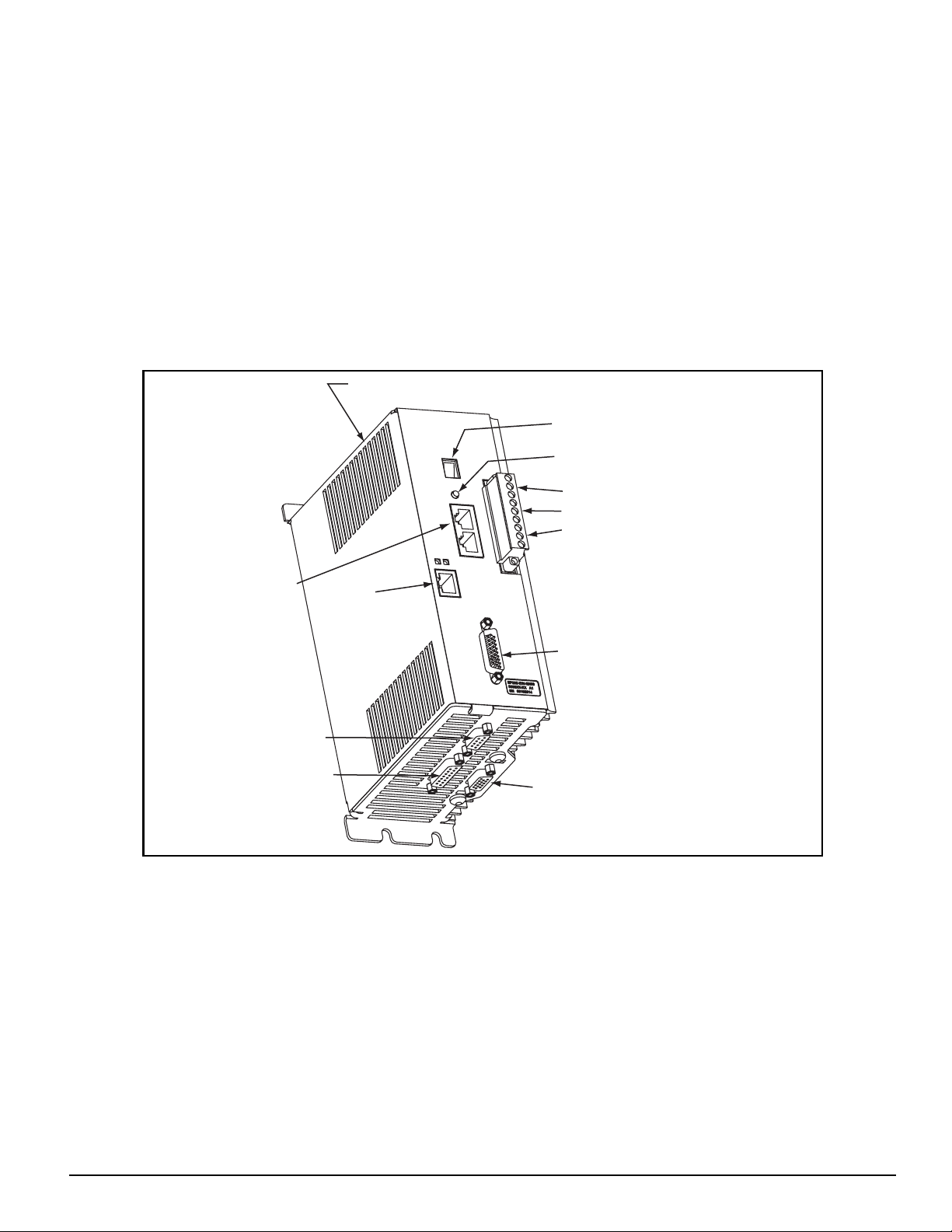
Epsilon EP Drive
The Epsilon EP drive is a stand-alone, fully digital brushless servo drive designed and built to reliably provide high
performance and flexibility without sacrificing ease of use.
The use of State-Space algorithms make tuning very simple and forgiving. The drives are designed to operate with up to a
10:1 inertia mismatch right out of the box. Higher (50:1 and more) inertial mismatches are possible with two simple parameter
settings.
The Epsilon EP drive can be quickly configured to many applications in less than 5 minutes with EMERSON Motion Control
PowerTools Pro software on a PC running Windows® 98, NT 4.0, 2000, ME and XP.
Complete diagnostics are provided for quick troubleshooting. A diagnostic display on the front of the drive informs the user
of the operational or fault status. The last 10 faults are stored in non-volatile memory along with a time stamp for easy recall.
Introduction
Shunt Connector (J8)
Diagnostic Display
Reset Button
Serial
Connectors (J2)
Sync Input Connector (J10)
Analog/Sync Output
Connector (J5)
Figure 1: Epsilon EP-P Drive Feature Location
FM-3 and FM-4
AC Power Connections
Motor Connections
24 Vdc Logic Power Supply Connections
Ethernet
Connector (J11)
(EP-Pxx only)
Digital I/O Connector (J3)
Encoder Feedback Connector (J6)
The FM-3/4 module is a compact and rugged function module that attaches to the front of the base drive. It provides eig ht
digital input lines and four digital output lines, in addition to the four input and three output lines available on the drive
module.
The FM-3/4 module offers complex motion profiling, along with multi-tasking user programs. A complex mo tion profile
consists of two or more indexes that are executed in sequence such that the final velocity of each index except the last is nonzero. Logical instructions between index statements can provide a powerful tool for altering motion profiles’on the fly’. The
FM-3/4 module defines complex motion by a configuration file that includes setups, function assignments and programs. The
configuration file is created using PowerTools Pro software. Setup views have the same look and feel as dialog boxes. The
wiring of input and output functions is done through assignments in the software. PowerTools Pro is an easy-to-use
Microsoft® Windows® based setup and diagnostics tool.
1
Page 14
Epsilon EP-P Drive and FM-3/4 Module Reference Manual
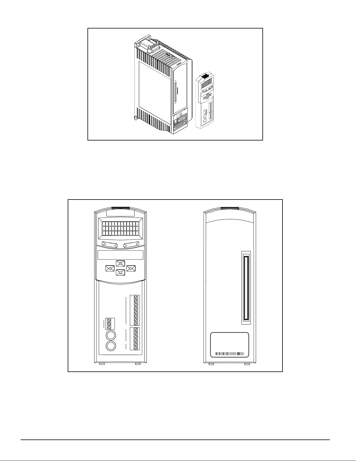
Figure 2: EN Drive with FM-3/4 Function Module
Note that the drive’s firmware is disabled whenever a Function Module, such as the FM-3/4 module is attached. Therefore,
if the drive’s hardware is FM compatible, then the drive’s firmware can be any version because the programming features
reside in the function module’s flash memory. Flash files used for firmware upgrades are available on the Control Techniques
webpage.
The FM-3/4 module stores drive setup parameters within the module itself. This allows you to transfer the FM-3/4 module
to another drive without losing setup parameters.
Programming Module
1
2
3
Inputs Outputs
4
5
485 +
485 SHLD
6
7
8
1
2
3
4
10-30
VDC
+
-
MODEL FM-4
PART 960498-01
REV
A1/A1
SER 0120B025
Exp. I/O
Sync.
Input
Output
Sync.
Figure 3: FM-3/4 Programming Module Features
2
Page 15

Epsilon EP-P Drive and FM-3/4 Module Reference Manual
This section provides a complete functional description of the Epsilon EP-P drive and FM-3/4 module . It is intended to
provide you, the user, with a thorough understanding of all operations. The description includes references to many FM-3/4
module and Epsilon EP-P drive parameters which can be displayed and/or edited using PowerTools Pro software, or through
any Modbus interface.
The FM-3/4 module augments the drive by providing the ability to implement programs written using PowerTools Pro. When
a FM-3/4 module is attached to a base drive, it overrides the operation and user accessible features of the base drive. The base
drive’s basic operating modes (Pulse, Velocity and Torque) are not available when a FM-3/4 module is attached.
The FM-3/4 module stores drive setup parameters within the module itself. This allows the user to transfer the FM-3/4 module
to another drive without losing setup parameters.
The Epsilon EP-P drive and FM-3/4 module allows the user to set up 55 different Indexes, Jog functions and a Home. The
FM-3/4 module provides eight digital input lines and four digital output lines in additio n to the fo ur input and three output
lines available on the base drive. The Epsilon EP-P drive provides fifteen digital inputs and eight digi tal outputs.
Software Interface
The Epsilon EP-P drive and FM-3/4 module is set up using PowerTools Pro software. PowerTools Pro is an easy-to-use
Windows® based setup and diagnostics tool. It provides the user with the ability to create, edit and maintain the drive’s setup.
You can download or upload the setup data to or from a device. The setup data can also be saved to a file on the PC or printed
for review or permanent storage.
Operational Overview
PowerTools Pro Setup Software
PowerTools Pro is designed to be the easiest-to-use software available for single axis motion controllers.
Features
• “Hierarchy Tree” for quick navigation to any setup view
• Simple I/O function assignments
• Powerful online diagnostic capabilities
• Programming
Figure 4: Hierarchy Tree
3
Page 16
Epsilon EP-P Drive and FM-3/4 Module Reference Manual
The “Hierarchy Tree” (shown above) contains expandable groups of parameters. The groups can be expanded and contracted
just like folders in Windows® Explorer. Left click on a view name in the Hierarchy Tree will display that view on the right
side of the computer screen.
To setup a drive the user simply steps through the Hierarchy Tree from top to bottom starting with the Setup view. Simple
applications can be setup in a matter of minutes.
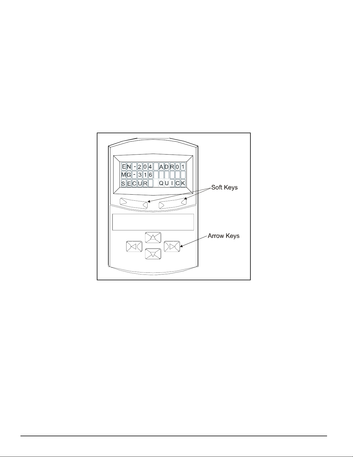
Keypad Interface of the FM-3/4 Module
The keypad and character display on the front of the FM-3/4 module provides navigation through a menu of common
parameters and displays current functions. Navigation through the menu is accomplished with the six keys located below the
display. The top two keys are called the “soft keys” because they relate to the commands located directly above each key on
the display. These keys are used to select the operation (e.g. Modify, Ok, Cancel), parameter group, and/or to validat e
information. The four arrow keys are used to navigate through parameter groups, select a specific parameter to be modified,
and to modify digital and numeric data.
The operation of the arrow keys is dependent upon the type of parameter which is being modified.
Figure 5: FM-3/4 Display and Keypad
On the Menu screen, the drive type and axis address are always shown on the top line of the display. The second line shows
the motor type. If a user defined motor is selected, the user defined motor name will appear. The third line shows two
parameter group names, one above each of the soft keys.
From the Menu screen, the user selects a group of drive parameters to work with. The group names are scrolled using the left/
right direction keys. The groups correspond roughly to the views used by the PowerTools Pro software. The groups are shown
cyclically and wrap around.
The drive parameters available with the FM-3/4 module keypad are arranged into seven groups (see list below). Upon powerup the FM-3/4 module will display the default parameter groups “SECUR” (left soft key) and “QUICK” (right soft key).
• QUICK (Quick)
• PROG (Program)
• INDEX (Index)
• HOME (Home)
• JOG (Jog)
• RAMPS (Ramps)
• SECUR (Security)
4
Page 17
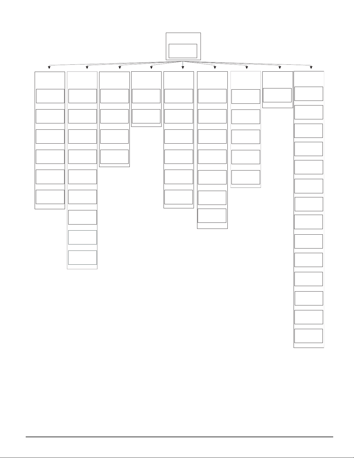
Menu
Screen
EN-204 Adr01
MG-316
SECUR
Operational Overview
PBus-
Group
Slave Address
MODIF MENU
Security: 1
Baud Rate
MENU
Security: 0
Network Sts
MENU
Security: 0
Module Sts
MODIF MENU
Security: 0
MasterAddr
MENU
Security: 0
MsgProcessed
MENU
Security: 0
DVNET+
Group
MacID
MODIF MENU
Security: 1
Baud Rate
MODIF MENU
Security: 1
Network Sts
MENUMODIF
Security: 0
Module Sts
MENU
Security: 0
Net OK
MENU
Security: 0
Conn Type
MENU
Security: 0
Mster MacID
MENU
Security: 0
Transmit Cntr
MENU
Security: 0
Receive Cntr
MENU
Security: 0
SECUR
Group
Auto Log Out
MODIF MENU
Security: 3
Password 1
MODIF MENU
Security: 3
Password 2
MODIF MENU
Security: 3
Log Out Now?
OK
Security: 0
* Jog Group contains 2 Jogs (Jog.0 and Jog.1)
Index Group contains 7 Indexes (Index.0 to Index.7)
Prog Group contains 4 Programs (Prog.0 to Prog.3)
+ DeviceNet Group is only available on FM-3DN and FM-4DN modules
- Profibus Group is only available on FM-3PB and FM-4PB modules
On all screens with < > symbols, scroll left and right to select the specific Instance
RAMPS
Group
Stop
MODIF MENU
Security: 0
Stop.Decel
MODIF MENU
Security: 1
JOG*
Group
<Jog.0.Vel>
MODIF MENU
Security: 1
<Jog.0.Accl>
MODIF MENU
Security: 1
<Jog.0.Decl>
MODIF MENU
Security: 1
<Jog.0.Plus>
MODIF MENU
Security: 1
<Jog.0.Mius>
MODIF MENU
Security: 1
Posn Fdbk Ct
MENU
Security: 0
HOME
Group
Home.0.Vel
MODIF MENU
Security: 1
Home.0.Accl
MODIF MENU
Security: 1
Home.0.Decl
MODIF MENU
Security: 1
Home.0.Init
MODIF MENU
Security: 1
Calc Offset
MENU
Security: 1
Spec Offset
MODIF MENU
Security: 1
Select Offst
MODIF MENU
Security: 1
INDEX*
Group
<Ind.0.Vel>
MODIF MENU
Security: 1
<Ind.0.Accl>
MODIF MENU
Security: 1
<Ind.0.Decl>
MODIF MENU
Security: 1
<Ind.0.Dist>
MODIF MENU
Security: 1
<Ind.0.Init>
MODIF MENU
Security: 1
PROG*
Group
<Prg.0.Init>
MODIF MENU
Security: 1
QUICK
Group
Posn Fdbk
GRAPH MENU
Security: 0
Vel Fdbk
GRAPH MENU
Security: 0
Following Er
GRAPH MENU
Security: 0
Axis Address
MODIF MENU
Security: 0
Baud Rate
MODIF MENU
Security: 3
DriveInput
MENU
Security: 0
ModuleInput
MENU
Security: 0
DriveOutput
MENU
Security: 0
ModuleOutput
MENU
Security: 0
Fault Sts 1
MENU
Security: 3
Fault Sts 2
MENU
Security: 0
Clear Fault?
OK MENU
Security: 0
Module Rev
MENU
Security: 0
Boot Rev
MENU
Security: 0
Parameter Screens
After selecting a group using one of the soft keys, the FM-3/4 module will display a Parameter screen for that group. This
screen could be either the first screen in the group or the last screen that was used in that group. The FM-3/4 module keeps
track of the last Parameter screen viewed in each group and returns to that screen when returning back to that group. This is
reset on power-up and the FM-3/4 module displays the first Parameter screen in the group.
In this screen, the parameter name is shown on the first line of the display. The up/down arrow keys are used to scroll through
the parameters available in the selected group. The second line displays the condition or value of parameters. The third line
displays the soft key actions.
The left/right arrow keys are used to scroll through the parameters when the “<“ and “>” symbols are shown.
5
Page 18
Epsilon EP-P Drive and FM-3/4 Module Reference Manual
Numeric parameter units are sometimes shown before the actual value, because the parameter value and the units cannot be
displayed on one line. The unit of measure will appear on the second line for about one second. Then the actual parameter
value will appear. The parameter value is updated about five times a second.
How Motion Works
The Epsilon EP-P drive and FM-3/4 module provides four types of motion: jogging, homing, indexing and gearing. Only one
index, jog, home or gear may be in process at any given moment (exclusionary motion types). Through assignments and
programs, the device can sequentially run various motion routines. The Positive direction parameter affects all motion types
by specifying which direction of motor revolution (CW or CCW) is considered motion in the “+” direction.
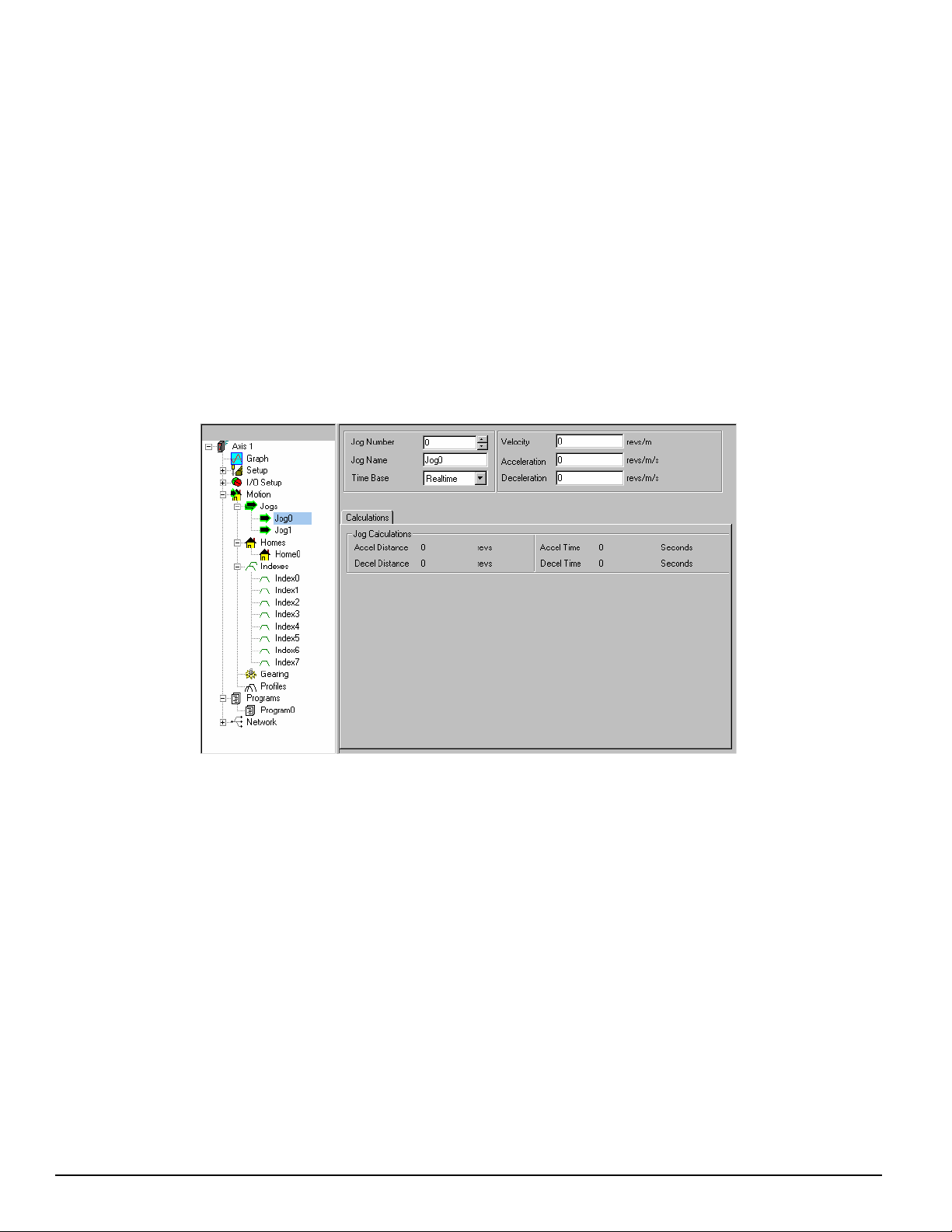
How Jogging Works
Jogging produces rotation of the motor at controlled velocities in a positive or negative direction.
Assignments to jogs are level sensitive such that when the jog input is turned on, jogging begins and continues jogging until
the jog input is removed.
Each jog has its own acceleration and deceleration ramp along with a specified velocity. Jogging has no distance parameter
associated with it. If trying to move a specific distance or to a known position, then an index is used.
Figure 6: Jog View
How Home Works
The Home is used in applications in which the axis must be precis ely aligned with some part of the machine. The Home is
initiated in one of three ways: with the Initiate Destination function found in the Assignments view, through a program, or
with the Online tab. A Home or Define Home is required to set the Absolute Position Valid so that any index to absolute
position can work.
The Epsilon EP-P drive and FM-3/4 module can home the motor to an external sensor, the motor’s encoder marker pulse, or
to a sensor and then to the encoder marker pulse.
6
Page 19

Operational Overview
External
Home Sensor
Carriage
Gear Reducer
NT Motor
with Encoder
-
Direction
+
Sensor Point
Home Offset
Distance
Figure 7: Basic Home Function, Example
The figure above show a basic home function using a ball screw. This example uses most of the setup features in the
PowerTools Pro Home view.
Home Sequence
1. Back off the sensor, if on the sensor. (This step is optional).
2. Move to the external home sensor to establish a home reference point.
3. Next it will move to the Offset position.
4. Then the command and feedback positions are set to the value entered into the End of Home Position.
Homing to the motor’s encoder marker will establish the most accurate and repeatable home position. This method will
position the motor relative to the location of the rising edge of the encoder marker pulse. Most applications will use a sensor
and marker to find an accurate home position in the vicinity of the home sensor.
Several parameters affect how the Home function operates. Each of these parameters are explained in detail on the following
pages.
Note
The Home function will NOT be initiated when any other motion command is in progress.
Establishing a Home Reference Position
The first step in setting up a home is to select the desired home reference type. The Home Reference type selected determines
how the Home Reference Position is established. PowerTools Pro allows selection of one of three different Home Reference
types: Sensor, Marker, or Sensor then Marker.
Sensor
Selecting Sensor means the rising edge of the Home Sensor input function is used to establish the home reference position.
Figure 8: Sensor Home Reference Position
7
Page 20
Epsilon EP-P Drive and FM-3/4 Module Reference Manual
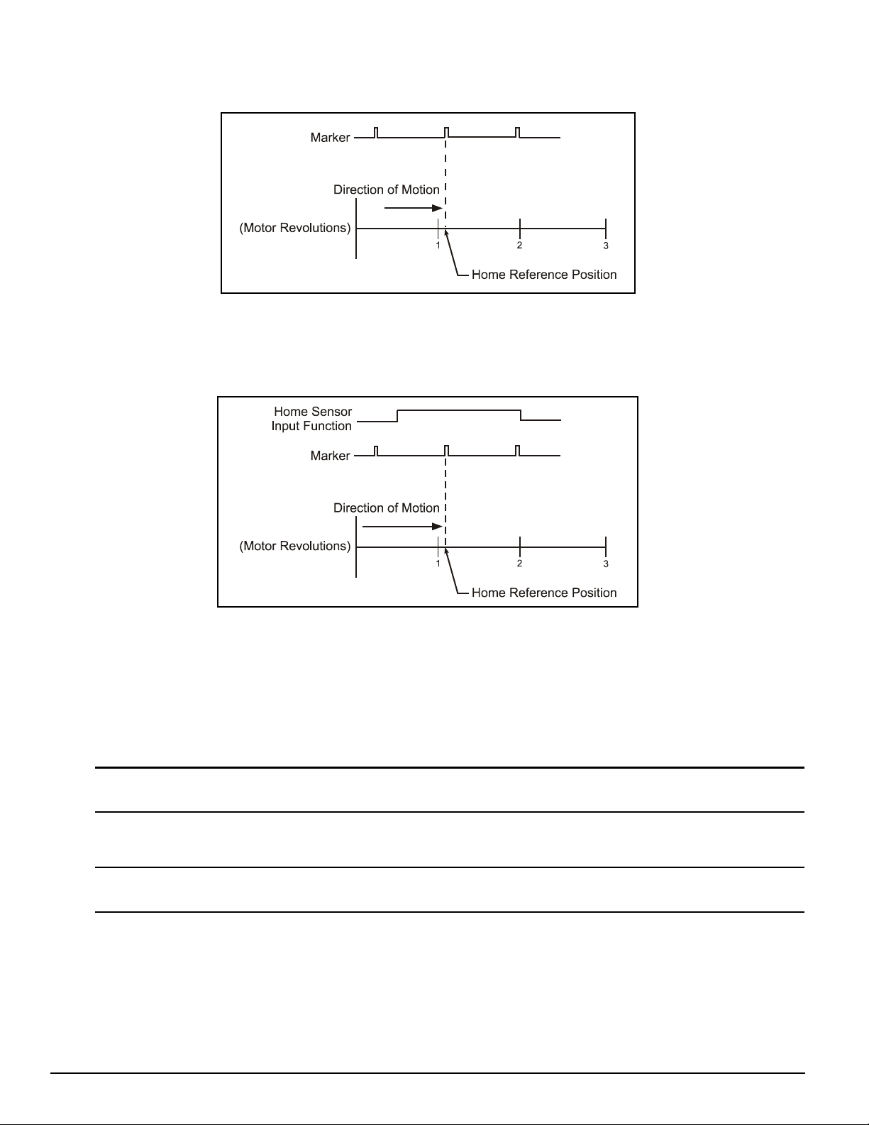
Marker
Selecting Marker means the rising edge of the motor’s encoder marker channel is used to establish the reference position.
Figure 9: Marker Home Reference Position
Sensor then Marker
Selecting Sensor then Marker means the reference position is established using the first marker rising edge after the device
sees the rising edge of the Home Sensor input function.
Figure 10: Sensor then Marker Home Reference Position Example 1
Accuracy and Repeatability
The accuracy is one trajectory update rate. For example - if the trajectory update rate is set to 800 µs then the accuracy will
be 800 µs, if the trajectory update rate is set to 1.6 ms then the accuracy will be 1.6 ms.
The amount of accuracy the application requires will determine the Home Reference type selected. Homing to an external
sensor will only establish a repeatable home position within 0.04 revolutions at 3000 RPMs (800 µsec sensor capture
interval).
Note
The data above assumes the use of a perfectly repeatable home sensor.
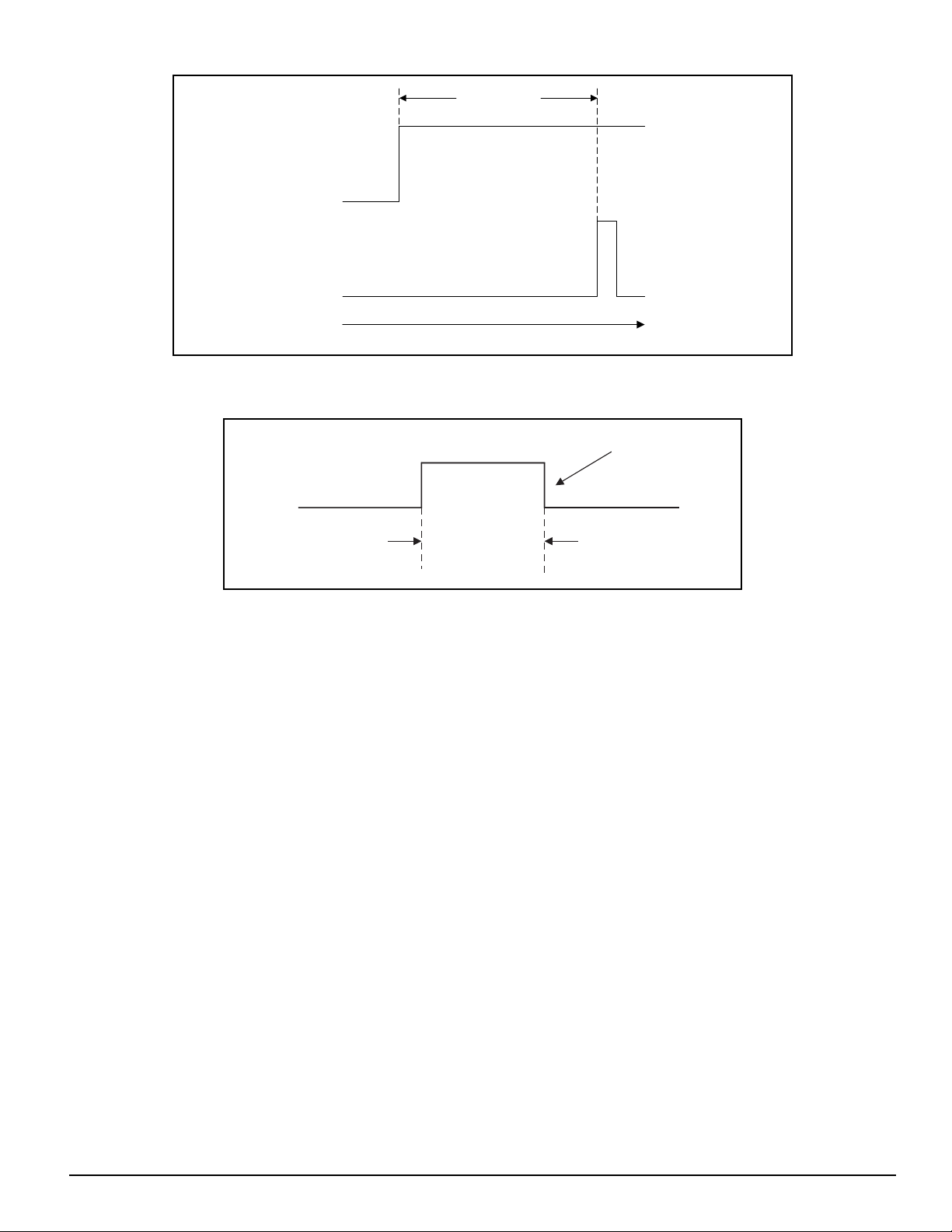
In Sensor then Marker applications, the marker must be at least 800 µsec after the rising edge of the sensor input to be
considered a valid marker pulse, see Figure 11.
Note
At 1000 RPM, the motor will travel 0.0133 revolutions (or 4.8°) in 800 µsec.
8
Page 21
>800 µsec
Sensor
Marker
Direction of Travel
Figure 11: Sensor then Marker Home Reference Position Example 2
The Home Sensor must be “On” for at least 800 µsec to guarantee that it will be recognized.
Sensor Min.
On Time
Sensor
Operational Overview
800 µsec
Figure 12: Sensor then Marker Home Reference Position Example 3
Home Offset
The Home Offset is the distance from the Reference Position to the final stopping point at the end of the homing sequence.
Regardless of the value you enter for the Offset or which Home Reference type you choose, there is always an offset inherent
in the homing process.
The user may either specify a desired offset or allow the drive to calculate an offset automatically. The drive calculates an
offset that guarantees that the motor will not have to backup to get to the offset position. This is very convenient for
unidirectional applications.
The Calculated Offset is the distance travelled during deceleration ramp from the home velocity to a stop plus the distance
travelled at the home velocity for 800 usec. This extra distance is used to guarantee that the motor will not need to backup
after the deceleration ramp.
The Specified Offset allows the user to choose an exact offset from the Home Reference.
Once the home reference is detected, the device will do whatever is necessary to reach the offset position. This may be as
simple as a deceleration to a stop, a continuation at speed followed by a deceleration to a stop, or a deceleration followed by
a move in the opposite direction.
To enter a specified home offset, select the Specified Offset radio button. PowerTools Pro always displays the calculated
offset value as a reference. If the home reference is detected before the axis has reached its peak velocity, the axis will still
continue to the precise offset position.
9
Page 22
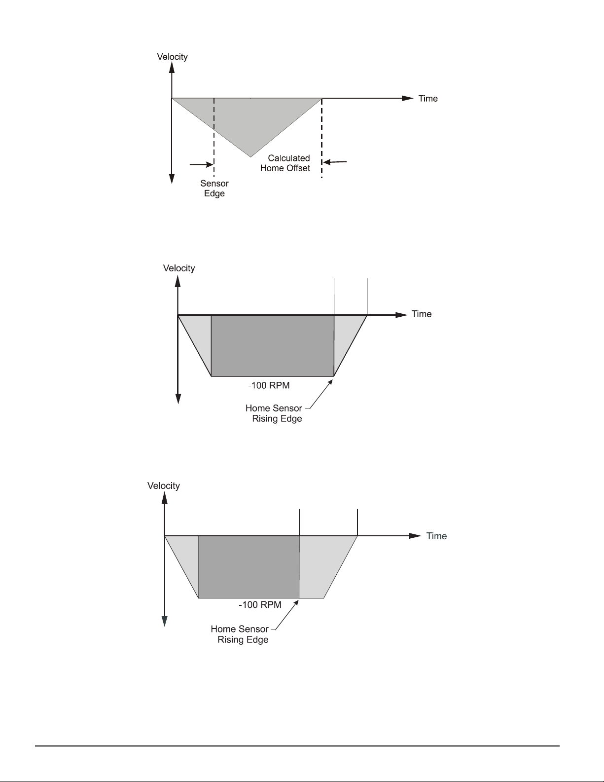
Epsilon EP-P Drive and FM-3/4 Module Reference Manual
Figure 13: Calculated Home Offset, Peak Velocity Not Reached
If the Home Reference is detected after the axis has reached its peak velocity, the axis will decelerate to the precise offset
position.
Calculated
Home Offset
Figure 14: Calculated Home Offset, Peak Velocity Reached
Two examples below show operation when the specified offset is greater or lesser than the calculated offset. This causes the
axis to continue on at speed before decelerating and stopping at the offset position, or backing up after the home sensor.
Specified
Offset
Figure 15: Specified Home Offset, Greater than Calculated Offset
10
Page 23
Operational Overview
Specified
Offset
Figure 16: Specified Home Offset, Backup Required
End of Home Position
The End of Home Position (End Posn) defines the home position in relation to the machine’s coordinate system. At the
completion of the home, the value of the End of Home Position is put into the command position.
Home Limit Distance
This parameter places an upper limit on the incremental distance the motor will travel during the home.
If no reference is found, the system will decelerate and stop at the limit distance. The Home Limit Distance Hit function will
be activated if the home stops at the limit distance without finding the reference. Additionally, the Home.CommandComplete
function will not turn “On” if the limit distance is hit.
Home Examples
Example 1: Linear Application
In this example, the system uses an external sensor and the motor’s encoder marker channel to establish a Home Reference
Position. This is the most accurate and most common way to home.
Gear Reducer
External
NT
Motor
Home Sensor
-
Direct
ion
+
Figure 17: Home to Sensor and Marker, Example
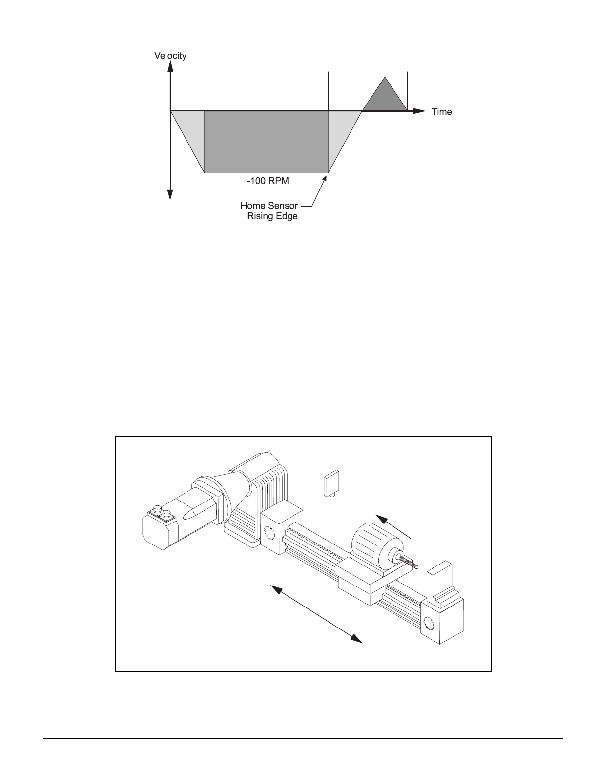
When the device sees the Home Initiate, it accelerates the motor to the Home Velocity.
11
Page 24
Epsilon EP-P Drive and FM-3/4 Module Reference Manual
The motor continues at that velocity until it first senses the Home Sensor input. It continues at the same velocity until the
motor’s encoder marker channel is sensed. The rising edge of the motor’s encoder marker channel is used to establish the
reference position. Once the home reference is detected, the motor decelerates to a stop and moves to the offset position.
Home Sequence
1. If on sensor then back off (if enabled)
2. Search for sensor
3. Search for marker
4. Go to offset (2.0 Revs)
5. Set feedback position equal to End of Home Position
Velocity
+ 100
Figure 18: Home Velocity Profile
Marker
Offset Move
2.0 Revs
Back off
Sensor
- 100
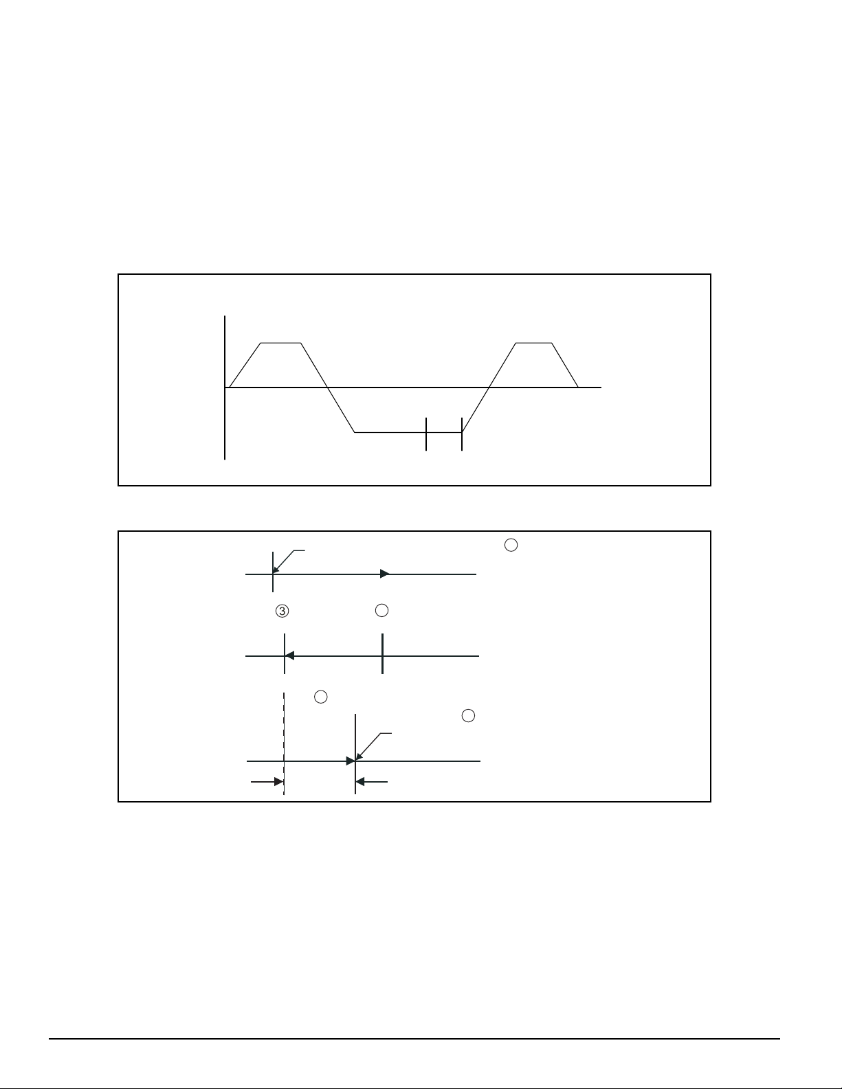
Start of Home
4
+ 100
Sensor
2
Sensor
Final Position = End of Home Position
Marker
1
Back Off Sensor
Home Move
5
Time
12
Offset
Figure 19: Home Move Sequence
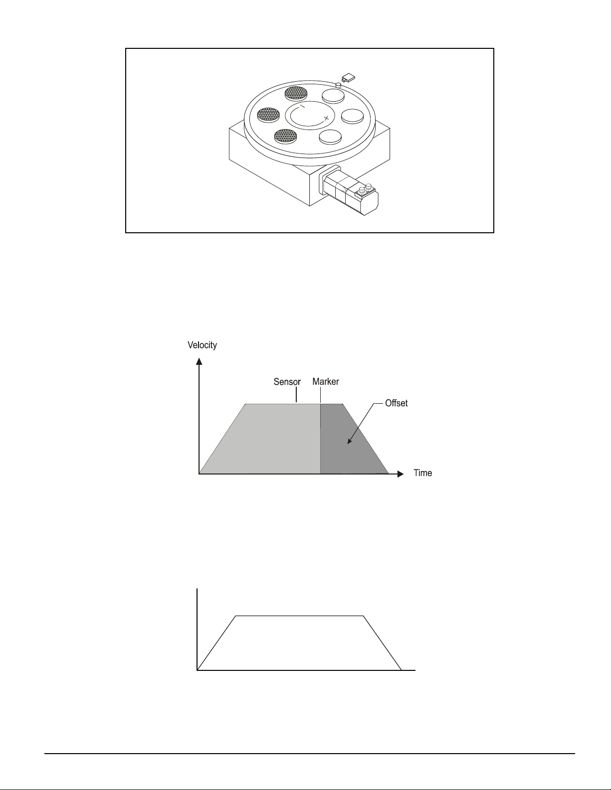
Example 2: Rotary Application
This example uses an external sensor and the motor’s encoder marker pulse to establish a home reference position.
Page 25
Operational Overview
External
Home Sensor
Gear
Reducer
NT Motor
Figure 20: Home Sensor and Marker then Offset, Example
When the device sees the rising edge of the Home Initiate function, it accelerates the motor to the Home Velocity. The motor
continues at that velocity until it first senses the Home Sensor input. The motor continues on at the home velocity until the
marker is activated.
The rising edge of the motor’s encoder marker channel is used to establish the reference position.
After sensing the rising edge of the motor’s marker channel, the device will continue moving and will decelerate to a stop at
the specified offset position.
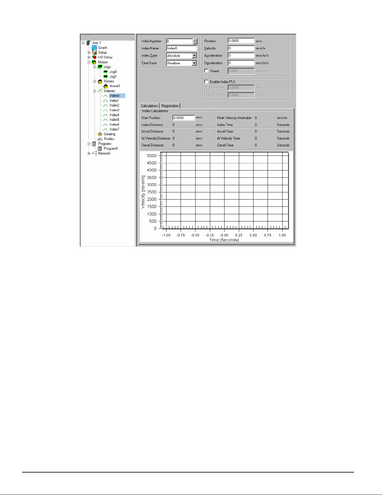
Figure 21: Home Velocity Profile
How Indexes Work
An index is a complete motion sequence that moves the motor a specific incremental distance or to an absolute position. This
motion sequence includes an acceleration ramp to a programmed velocity, a run at velocity, and a deceleration ramp to a stop.
Figure 22: Index Motion Sequence
Velocity
Acceleration
Run at Velocity
Deceleration
Time
13
Page 26
Epsilon EP-P Drive and FM-3/4 Module Reference Manual
Figure 23: Indexes View
Indexes use acceleration and deceleration ramps which may or may not reach the specified velocity depending on the total
distance and the ramp values. For example, a short move with long acceleration and deceleration ramps may not reach the
target velocity entered.
Indexes cannot be initiated when any other motion (jogging, homing, or program) is in progress. Indexes can be aborted with
the Stop destination found in the Ramps group on the Assignments View.
The FM-3/4 module supports five types of indexes: absolute, incremental, registration, rotary plus and rotary minus.
Absolute vs. Incremental
The difference between absolute and incremental indexes is that absolute indexes move to a specific absolute position and
incremental indexes move the motor a specific distance. The figures and explanations below demonstrate this concept.
Absolute Indexes
Absolute indexes are used in applications where the motor must travel to a specific position, regardless of where the motor
is when the index is initiated.
The device calculates the distance required to move to the specified position from the current position.
14
Page 27
Operational Overview
Absolute Index
Start Position = 1 Rev
Index Position = 5 Revs
Figure 24: Absolute Index Example 1
In the example above, the current position is 1 rev. If this index is initiated, the motor will travel to a position of 5 revs no
matter where it is sitting before the move. From 3 revs, it will travel 2 revs to finish at 5 revs. If the absolute index to 5 revs
is initiated a second time immediately after the index, no motion will occur because the motor will already be at a position of
5 revs.
The direction of an Absolute Index is determined by the starting position and the absolute index position. If the starting
position for the above index is 9 revs, then the motor will rotate in the negative direction to end up at 5 revs. The figure below
shows this.
Absolute Index
Start Position = 9 Revs
Index Position = 5 Revs
Figure 25: Absolute Index Example 2
Absolute indexes with Rotary Rollover enabled will take the shortest path to the position entered in the index position
parameter.
Note
Absolute indexes move to positions relative to where the machine was homed using the Home, or the DefineHome
destination.
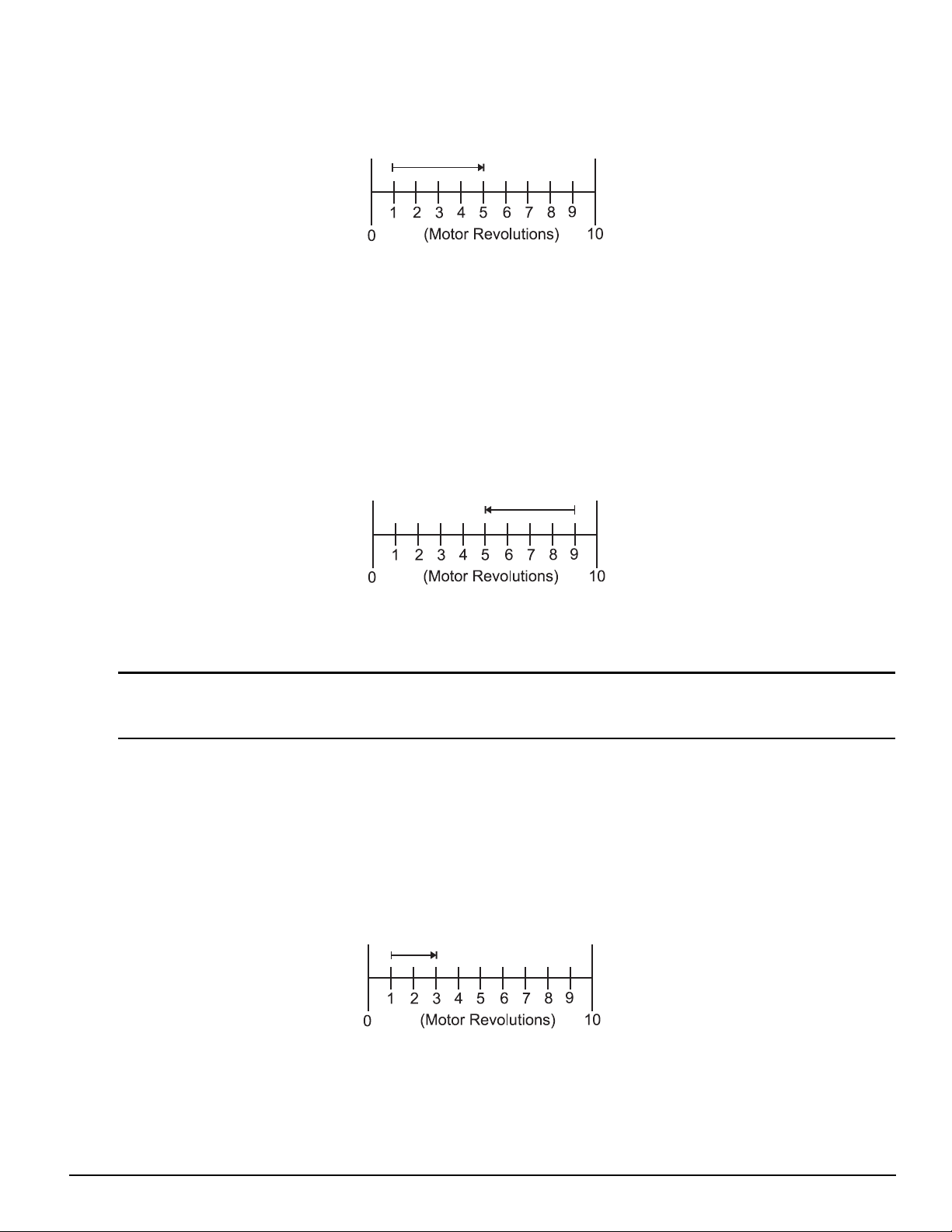
Incremental Indexes
An incremental index will move the motor a specified distance in the + or - direction regardless of the starting position. The
direction of the incremental index motion is determined by the sign (+ or -) of the Index Distance parameter.
Incremental Index
Incremental Index
Start Position = 1 Rev
Index Distance = 2 Revs
Figure 26: Incremental Index Example
In the example above, the motor starts at 1 rev, travels a distance of 2 revs and stops at 3 revs. If the same index is initiated
a second time, the device would move the motor another 2 revs to a position of 5 revs. If initiated a third time, the motor
would travel another 2 revs to a final position of 7 revs. The figure below shows this operation.
15
Page 28

Epsilon EP-P Drive and FM-3/4 Module Reference Manual
Incremental Index
Start Position = 1 Rev
Index Distance = 2 Revs
Figure 27: Incremental Index Example 2
Registration Index
A Registration Index is used in applications where the motor must move until an object is detected and then move a specific
distance from the point of detection, such as finding a registration mark and moving a distance beyond.
The Registration Index consists of two parts. The first part accelerates the motor to the target velocity and continues at this
velocity until it receives a registration trigger (sensor or analog). Upon receipt of a registration trigger, the registration offset
will be executed at the target velocity. The Sensor Limit Distance Hit source can be used to turn on an output, if a sensor input
or analog limit is not received within the Limit Distance. A registration window can also be used to determine the validity of
a registration trigger. If a registration trigger is received outside of the registration window, it will be ignored.
Rotary Plus and Rotary Minus Indexes
Rotary Plus and Rotary Minus Indexes provide forced directional control of moves to absolute positions. The position entered
for a Rotary Plus or Minus type index must be within the rotary range (i.e. 0 ≤ Position < Rotary Rollover Point). All other
parameters function the same as they do with absolute indexes. An Absolute Index is a direct move to a specific position,
regardless of the starting point. A Rotary Plus Index moves to the specified position, but is forced in a positive direction.
Similarly, a Rotary Minus index moves to the specific position, but is forced in a negative direction.
Rotary Plus and Minus Indexes are usually used in rotary applications, therefore the rotary rollover feature on the Setup Position view in the PowerTools Pro software must be enabled to use them.
1. In the following examples the term “D” = (absolute position specified) - (current position). If “D” is negative, motion in
the negative direction is implied.
2. In the following examples the Rotary Rollover parameter on the Setup - Position view is set to 360.00°. This means that
with each revolution of the motor (or rotary table), feedback will count up to 359.99°, then roll over to Ø°.
Indexes with Rotary Rollover Enabled
Incremental move distances can be outside of the rotary rollover range. See the "Setting Up Parameters" chapter for an
explanation of Rotary Rollover.
Example 1: If the starting position is at Ø° and 720° is the specified distance, an Incremental index would move 2
revolutions in the positive direction. At the completion of this index the motor position would be Ø°.
Absolute indexes will take the shortest path to the specified position. Absolute index positions must be within the rotary
rollover range.
Example 2: If the starting position is at 90° and 80° is the specified position, an Absolute index would travel 10° in the
negative direction. At the completion of this index the motor position would be 80°.
Example 3: If the starting position is 45° and 315° is the specified position, an Absolute index would travel 90° in the
negative direction because that is the shortest path between 45° and 315°.
Rotary Plus indexes will move to the specified position and are forced in a positive (or plus) direction. Rotary Plus index
distances must be within the rotary rollover range.
16
Example 4: As in example 2 above, the starting position is at 90° and 80° is the specified position. A Rotary Plus index
would travel 350° in the positive direction. At the completion of this index the motor position would be 80°.
Example 5: If the starting position is 10° and the specified position is 350°, a Rotary Plus index will travel 340° in the
positive direction.
Page 29

Rotary Minus indexes move to the specified position, but are forced to travel in the negative (or minus) direction. Rotary
Minus index positions must be within the rotary rollover range.
Example 6: As in examples 2 and 4 above, the starting position is at 90° and 80° is the specified position. A Rotary
Minus index would travel 10° in the negative direction. At the completion of this index the motor position would be 80°.
Example 7: If the starting position is 15° and the specified position is 270°, a Rotary Minus index would travel 105° in
the negative direction.
How Communications Work
Configuring Communication
Before attempting to upload or download a configuration file using PowerTool Pro, the software must be configured to the
correct communication settings for the intended communication connection. The FM-3/4, FM-3/4DN and FM-3/4PB support
a serial communication connection, either RS-232 or RS-485. The FM-3/4E supports both serial and Ethernet communication
connections.
The communication connection may be selected in the Upload Drive Configuration, Download to Device IDx or the Change
Path dialog boxes. From the Device menu, choose Upload Drive, Download or Path Change to open the dialog box or the
toolbar buttons can also used, see below.
Uploading
Uploading is the process of reading information back from the drive to the PowerTools Pro configuration file views.
Operational Overview
To upload information from a drive, click on the Upload All button, on the PowerTools Pro toolbar or from the
Device menu, choose Upload All or Upload Drive. The Upload Drive Configuration dialog box will open, all
communication connections are scanned and the results appear. In Figure 28, it shows that one device on COM 1
was found, an Epsilon Eb-205 drive. The Upload Drive Configuration dialog box contains the following
information for every device found:
• Ip Address/COM
• Modbus Address ID
• Drive Type
• Module Type
• Communication Options
• Base/Drive FW Revision
• Module FW Revision
• Module Serial Number
• Drive Serial Number
17
Page 30

Epsilon EP-P Drive and FM-3/4 Module Reference Manual
.
Figure 28: Upload Drive Configuration Dialog Box
Select the device to upload and click Upload.
Downloading
Downloading is the process of sending the configuration created with PowerTools Pro from the PC to the device. Changes
made in PowerTools Pro will not take effect until the information has been downloaded or the Update to RAM button has
been clicked.
To download information to a device, click the Download button on the PowerTools Pro toolbar or from the Device
menu, choose Download. The Download to Device IDx dialog box will open, all communication connections are
scanned and the results appear. In Figure 29, one device on COM port 1 was found, it’s a EN-204 with FM-3/4DN
module. The Upload Drive Configuration dialog box contains the following information for every device found:
• Ip Address/COM
• Modbus Address ID
• Drive Type
• Module Type
• Communication Options
• Base/Drive FW Revision
• Module FW Revision
• Module Serial Number
• Drive Serial Number
18
Page 31

Figure 29: Download to Device ID 1 Dialog box
Select the device to download to and click OK.
Operational Overview
Change Path Connection
This function allows the user to change the drive and Ip address/Com port used for download and upload. It is used when the
user has already selected one Ip address Com port and wishes to change to another.
The dialog box provides the user with communication information available on the Modbus and Ethernet network (if
appropriate). This information contains:
• Ip Address/COM
• Modbus Address ID
• Drive Type
• Module Type
• Communication Options
• Base/Drive FW Revision
• Module FW Revision
• Module Serial Number
• Drive Serial Number
19
Page 32

Epsilon EP-P Drive and FM-3/4 Module Reference Manual
Figure 30: Change Path Dialog Box
Select the device in the list and then click OK. The communication connection path will then be displayed in the status bar at
the bottom of PowerTools Pro window.
NVM Options for Uploading and Downloading
Uploading
When uploading from a device, the values that were last downloaded are uploaded and put into a PowerTools Pro
configuration file. At the completion of the upload, the user will be asked if they wish to upload the NVM values. This dialog
box is shown below.
By selecting Yes, the values of all parameters stored in NVM will be uploaded and entered into the PowerTools Pro file
values. If No is selected, the values entered into the PowerTools Pro file will remain the same as those that were last
downloaded to the device.
Downloading
When downloading to the device the user will be required to select how to handle the NVM parameters upon downloading.
The dialog box asking the user to select one of three options for the download is shown below.
20
A description of each of the options is as follows:
Overwrite – This option will overwrite all the parameters stored in NVM with the current values in the user configuration
(PowerTools Pro file). The values that are in NVM prior to the download will be lost.
Page 33

Operational Overview
Update – This option will upload the current NVM parameter values from the device and enter them into the user
configuration (PowerTools Pro file). Once the NVM values have been stored in the file, the file is fully downloaded.
Keep – This option will download the entire user configuration, but then NVM parameters will be restored to the value prior
to download. This is similar to the Update option, but the Keep option does not upload the NVM values into the user
configuration (PowerTools Pro file).
The following table shows an example of how these options work:
PT Pro file value for
Updating to RAM
The Update to RAM button can be used to send changes to the device without performing a complete download.
The Update to RAM button is found in the PowerTools Pro toolbar. This operation will send only those changes
that have been made since the last Update to RAM or a Device>Download to the device was done. The changes
will take effect immediately upon clicking on the button.
The parameters will be sent to the device without stopping motion or disabling the drives. Because of this, it is important
to use caution when changing motion parameters while the motor is in motion.
The Update to RAM button saves the parameters only to RAM and not to Non-Volatile Memory (NVM). Therefore, if the
system power is removed, any changes made using the Update to RAM button will be lost. In order to save changes to NVM,
a full-download must be performed.
The flowchart below describes a typical process using the Update to RAM to make changes, and then downloading when
complete to save changes to NVM.
Index.0.Vel
NVM value for
Index.0.Vel
Before
Download
150 150 500 150
500 150 500 500
Overwrite
Option
After Download
Update
Option
Keep
Option
Figure 31: Update to RAM Flow Chart
The Update to RAM button operates according to the following rules:
• If no parameters have been modified by the user, the Update to RAM button will be disabled
• If the user modifies a parameter that does not require a full download, the Update to RAM button will be enabled
• If while the button is enabled, the user modifies a parameter that requires a full download, the Update to RAM button will
become disabled
• When the user clicks on the Update to RAM button, all the modified parameters are transmitted to the device. Once
transmitted, the button will become disabled again until another parameter is changed
• If the user performs a full download while the button is enabled, when the download is complete, the Update to RAM
button will be disabled
21
Page 34

Epsilon EP-P Drive and FM-3/4 Module Reference Manual
• If the user modifies parameters, and disconnects, the update button will be disabled, and the changes will not be sent.
Options/Preferences/Ptools Operation
Communications Tab
This dialog box allows the user to set-up the serial communication baud rate, the drive baud rate and the PowerTools Pro baud
rate must match. Default drive baud rate = 19200. The maximum number of node addresses and what communication
connections are scanned when doing any communication operations. Default = All ports are scanned.
Figure 32: Preferences-Communications Tab
PopUps Tab
The options in this dialog box controls the dialog boxes that the user encounters when uploading and downloading the
configuration file.
22
Figure 33: Preferences-PopUps Tab
Page 35

Operational Overview
Download Section:
Ignore saving file on Ptools/Drive revision conversion.
On a download PowerTools Pro checks the firmware revision of the device that it is about to be downloaded to and is required
to make changes to files that are to be downloaded to older firmware revisions. This check box allows the user to avoid saving
the newer file before converting it to a previous revision.
Overwrite – Reset the NVM configuration.
When this option is selected the “Overwrite” function will default on every download to the module. This functi on will
overwrite the entire configuration including user defined NVM param eters a s set in the NVM setup area of PowerTools Pro.
Note
It is required to Overwrite the Non-Volatile Memory on the first download to the module since no Non-Volatile Memory
parameters have been loaded into the drive on initial startup.
Update – Upload the values into the current Update PowerTools configuration.
When this option is selected the “Update” function will Update the NVM on every download to the module. Upon download
the Update function uploads the configured NVM from the drive and places the data into the PowerTools Pro configuration
file. The software then downloads this newly updated file to the module.
Keep – Remember the values, and restore them after the download.
This option was created to allow users to save the values that have been changed via HMI, PLC or internally in a program so
long as they have been added to the NVM list. When this option is selected PowerTools Pro will poll the drive on download
for all of the values that have been added to the NVM list. PowerTools Pro then stores these values into a temporary memory
location and after the program download is complete PowerTools Pro reinstates these values to the parameters before the
drive can be enabled.
Ask on each download.
This option was created for users who want control of whether they will overwrite or keep the NVM on download. When this
option is selected, PowerTools Pro will display a pop-up window that gives the user the option to Overwrite, Update, or Keep
as described above.
Upload Non-Volatile Memory (NVM) Section:
Always upload NVM
When this option is selected, PowerTools Pro will default on an upload to uploading all of the parameters that have been
mapped to the NVM and updating the display of these parameters in PowerTools Pro.
Always bypass NVM upload
When this option is selected, PowerTools Pro will not upload the NVM and the values that were originally downloaded to
the drive will be displayed in the PowerTools Pro configuration.
Ask on each upload
When this option is selected, PowerTools Pro will default to asking the user via a dialog box whether to upload the NVM or
to bypass the NVM upload.
Secure Downloading
The Secure Download feature allows the user to download a configuration that prevents anyone from uploading the file, or
going online with the system. This is used to protect a file from being accessed by unauthorized personnel. If a secure file
is downloaded to the system, all diagnostics capabilities in the software are lost. The only way to go online with the system
again is to download the original (non-secure) file over the secure version, or to download a completely new file.
Before performing a secure download, the file must first be saved in the secure file format. To do this, open the file you wish
to save in the secure format using PowerTools Pro. Then on the File menu, click SaveAs. The following SaveAs dialog box
should appear when saving an FM-4 configuration file.
23
Page 36

Epsilon EP-P Drive and FM-3/4 Module Reference Manual
In this dialog box, select the “Save also as secure download format” check box located at the bottom of the dialog box, then
click Save. Doing this will save the file in BOTH the standard file format (.fm4), as well as in the secure file format (.fm4s).
The “s” at the end of the file extension stands for “secure”. The secure file will be saved to the same directory as the standard
file.
To perform the Secure Download, close all open files in PowerTools Pro. Then on the Device menu, click Secure Download,
as shown below.
A dialog box will then open asking the user to select the secure file that they wish to download. Select the secure file that was
just saved, then click Open. This will download the secure file to the target device.
A secure file (.fm4s) cannot be opened or modified. The file extension cannot be changed to allow the user to open it. The
secure file is only valid for use by the secure download function. If a user attempts to upload a secure file, a message will
appear indicating that the file residing in the device has been protected by the user. An example of this is shown below.
Brake Operation
The motor brake operation is controlled by the Brake Release and Brake Control destinations. These destinations can be used
together to control the state of the Brake source. The table below shows the relationship between the Brake sources and
destinations (see “Diagnostic Display”).
Note
No motion should be commanded while the brake is engaged.
Brake Release Destination Off On
Brake Activate Destination On Off On Off
Drive Power
Stage
Enabled
Disabled
0111
0011
Brake Release
The Brake.Release destination function will release the brake under all conditions. When this function is active, the Brake
output will be on (that is, release brake). This function overrides all other brake control, thus allowing the brake to be released
while a fault is active or the power stage is disabled. See also Brake source function.
24
Page 37

Brake Activate
The Brake.Activate destination function, when active, will engage the brake unless overridden by the Brake Release function.
This function lets you externally engage the brake while allowing the drive to also control the brake during fault and disabled
conditions.
Brake Disengaged
The Brake.Disengaged source function is used to control the motor holding brake. If the Brake function is off, the brake is
mechanically engaged. When the brake is engaged, the diagnostic display on the front of the drive will display a “b”.
The drive outputs are limited to 150 mA capacity, therefore, a suppressed relay is required to control motor coil. Control
Techniques offers a relay, model # BRM-1.
How Data Capture Works
Data Capture is a mechanism to capture data and display that data graphically. The capture mechanism is part of the drive
and captures drive data as fast as 100 usec. Data is captured in a circular 8 K byte buffer . The format is fixed at 4 channels of
32 bit words for a total of 512 time samples. The circular buffer is continuously loaded until the trigger condition (or command abort) stops loading data. The capture mechanism follows three buffer states - Filling Buffer, Waiting for trigger, and
Triggered.
At the start of the Run command, the buffer starts to fill (filling the whole buffer). The buffer must be completely filled
before the trigger is armed. Once the buffer is filled, the buffer state will display - Waiting for Trigger. When the trigger is
detected, the data capture is stopped (triggered). The sampling rate is based on the trajectory update rate. The sample rate
can be adjusted in multiples of the trajectory update rate. PowerTools displays this in the form of seconds. At the update
sampling, a new set of data is overwritten into the circular buffer and the trigger is checked.
Operational Overview
For Data Capture, the update rate for MDS drive modules is 100 usec for switching frequency of 10 kHz and is 200 usec for
5 kHz. The FM-3/4 module passes data to the drive at the user selectable trajectory update rate of 800, 1200 or 1600 usec.
This means if the Data Capture rate is faster then the FM-3/4 module trajectory update rate the user will be sampling data
faster than it is changing.
The trigger detection checks the data level. It does not specially look for an edge. Once the buffer is filled the trigger is
armed and the check for trigger level is started. Since the drive is looking back in the buffer at data captured during the fill,
the trigger condition may already exist. If that is so, the drive immediately transitions to the trigger state. If not, the drive
continues the data capture cycle of sample and trigger check until the trigger is detected at the edge of the data transition.
When the Trigger Falling Edge check box is selected the trigger is detected when the data transitions below the trigger level.
When sampling digital inputs and outputs, the data captured is binary bit mapped. The state of all the digital signals in the
group selected are encoded into one 32 bit word. When this is graphed it is displayed as an analog signal. To trigger on this
bit map data, the trigger mechanism is changed to a mask. The user can select one of the bits to trigger on.
The captured data is uploaded when the UploadPlot button is pressed. Once uploaded, PowerTools plots the data in graph
window. Data is also saved in a data file named, PtProGraphData.csv. This data file can be exported to a spread sheet for
data manipulation and graphing.
Navigating the Graph Window
The Graph window display can be altered, double-click anywhere in the Graph Window except on the graph area itself. The
Customization dialog box opens and contains tabbed graph options. Many of the graphs attributes, such as colors, line format, etc. can be changed in this box. The graph can also be exported to a file.
Holding the shift key down while moving the mouse allows the user to zoom in on the graph area. Double-click on the graph
area and the Graph Coordinate window opens and gives the x/y coordinate of where the mouse point was when doubleclicked.
The Graph window overlaps the data into a Y axis if the next channel has the same units. If the units change for the next
channel, a new graph on the Y axis is added to the plot. If None is selected for a channel the drive data capture samples zero
for that channel an PowerTools ignores plotting that channel. The Reserved channel selection is for internal use only and
also captures zero. The title of the graph matches the application’s name defined on the Setup view.
Graph settings are downloaded to the drive when the Run button is pressed. Only changed values are sent. The graph settings are the same as any application variable. When a variable is changed in a PowerTools view the Update to RAM button
25
Page 38

Epsilon EP-P Drive and FM-3/4 Module Reference Manual
is available, indicating the application and drive are out of sync, (Update to RAM remains unavailable if the user changes a
variable that requires a reboot. The user then requires a full download). When the Run button is pressed, it does a limited
Update to RAM by downloading the changed graph settings to RAM.
26
Page 39

Epsilon EP-P Drive and FM-3/4 Module Reference Manual
Graph View
Setting Up Parameters
Figure 34: Graph View
Data Capture Group
Graph State
There are three graph state conditions in the following order: Filling Buffer, Filled. Waiting for Trigger, and Filled and
Triggered.
Run
The Run button commands the drive to begin a high speed data capture of the parameters as selected in each of the four data
channels. After the Run command button is activated the buffer will fill up to the trigger offset while the words “Filling
Buffer” appear indicating this Graph State. Once the trigger offset level is reached the words “Waiting Trigger” will appear
next to the Graph State indicating that graphical monitor is now ready to be triggered based on the trigger level selected. The
Run command button may be activated by the letter “R” on the keyboard.
Upload and Plot
The Upload and Plot button will upload captured data from the drive and display this data in the Graph window. The user
should wait for the Graph State to read “Filled and Triggered” before the data is uploaded.
Stop
The Stop button stops the data capture with the data captured at that point. You can upload and plot that data. If the buffer is
only partially filled you will get a combination of good and bad data. Stop works well as a manual trigger, in place of the
configured trigger.
Automatically Re-trigger and Plot Check Box
Select the check box and the Automatically Re-trigger and Plot tells PowerTools to monitor the graph state for the triggered
condition. When this condition occurs, it automatically initiates the UploadPlot command, waits for a brief time then initiates
the Run button to repeat the cycle. Initial the user must press the Run button to start the auto cycle.
This mechanism is only active when the graph view is displayed, If the user enters a different PowerTools view the auto
update will stop and it will restart when returning to the Graph view.
The Print button is used to print the graph in the Graph window.
27
Page 40

Epsilon EP-P Drive and FM-3/4 Module Reference Manual
Timing Group
The sliders can be moved in several different ways.
1. With the mouse pointer over the slider, left click and hold while dragging the slider back or forth to the desire setting.
2. With the mouse pointer over the slider, left click on the slider and then the arrow keys on the PC keyboard can be used to
move the slider in fine increments. The Page Up and Page Down keys move the slider in course increments. The Home key
will move the slider all the way to the left and the End key will all the way to the right.
Sample Rate
The Sample Rate slider gives the user control of time spacing for the captured date. To give the user a better idea of what this
number means, the total number of samples and total capture time is displayed on the bottom of the “Timing” group box.
Trigger Offset
The Trigger Offset slider corresponds to the number of samples that will be included on the graph display and data capture
prior to the actual trigger. If the Trigger offset slider is completely to the left (min samples), the data capture and graphing
will start at the trigger location. If the slider is completely to the right (max samples) the graph will capture data until the
trigger point.
Buffer Upload Size
The buffer upload size slider truncates the drive captured data. If the slider is completely to the right (max) the complete buffer
will be uploaded. If the slider is completely to the left, only 1% of the buffer will be uploaded. This parameter does not effect
the data capture size, it only defines how much of th e buffer will be uploaded.
Data Group
Data Channel 1 - 4 Select List Boxes
The Channel 1 through Channel 4 list boxes give the user options for parameter display. If parameters with the same units
are mapped on adjacent channels then the graphical display will show these two parameters overlapped on the same x/y axis.
If it is desirable to have two adjacent Channels with the same units mapped to separate axis on the graph then the selection
(none) should be used on the channel in between these two parameters.
Trigger Radio Buttons
Selecting the radio button will cause the graphical capture to trigger the capture off the selected Channel. The “Trigger Level”
text box on the bottom of the display will change units to the selected channel's parameter units. This trigger level may be
changed at any time but the change must be sent to the drive via the Update to RAM or Download button. If a manual trigger
is desired, set the channel to None and select the corresponding trigger radio button. If no trigger is selected the capture will
begin when the Run button is clicked and end at the end of the Sample Rate.
Module Parameter
A Module parameter text box is only available once the user has selected Module Parameter from the Select list box. This
field is used to define what parameter will be plotted on that channel. The module parameter can be entered two ways: by just
typing any module parameter using the program format for the variable, or click the Popup Variables button and the variable
window will open. Then select the variable and drag it over to the channel module parameter text box.
Trigger Mask List Box
This list box is only available when Drive Inputs, Drive Outputs, Module Inputs or Module Outputs is selected in the channel
select list box and the Trigger radio button is selected for that channel. The Trigger Mask list box will only list the inputs or
outputs for the selected channel parameter.
Trigger Falling Edge Check Box
When the Trigger Falling Edge check box is selected, the trigger is detected when the data transitions below the trigger level.
When the Trigger Falling Edge check box is clear, the trigger is detected when the data transitions above the trigger level.
Trigger Level
This is the level at which the graph is triggered. The “Trigger Level” text box will change units to the selected channel's
parameter unit. This trigger level may be changed at any time but the change must be sent to the drive via the Update to RAM
or Download button.
28
Page 41

Setup View
The Setup View contains all of the primary system setup parameters. These parameters must be setup prior to using your
system.
By selecting Setup in the Hierarchy Tree, the Setup view will appear on the right side of the view (see Figure 35). The Setup
view is divided into six groups, with an explanation of each function. The groups are Identification, Configuration, Drive
Encoder Output, Positive Direction, Update Rate and Switching Frequency.
Setting Up Parameters
Figure 35: Setup View-Epsilon EP-P Drive
Identification Group
The identification group consists of the Device Name and the Target Drive Address for all non-Ethernet FM-3/4 modules.
The FM-3/4E module and Epsilon EP-P drive will also have IP Address, Subnet and Gateway.
Name
This is a 12-character alpha/numeric user-configured name for this axis. Enter this name for the device currently being set
up. Assigning a unique name for each device in the system allows the user to quickly identify a device when downloading,
editing, and troubleshooting. All keyboard characters are valid. This will default to Axis 1.
Target Drive Address
This is the Modbus address of the target drive to which the user will download the configuration. The default target drive
address is 1.
IP Address (FM-3/4E and Epsilon EP-P only)
This is a 32-bit identification number for each node on an Internet Protocol network. These addresses are represented as four
8-bit numbers (0 to 255), with periods between them. Each node on the Ethernet network must have a unique IP address.
Subnet (FM-3/4E and Epsilon EP-P only)
This 32-bit parameter indicates the subnet mask used for this node. The subnet mask is used to group devices that are
connected on the same physical connection. For a detailed description of Subnet mask refer to the Industrial Ethernet
Overview section in the FM-3 and FM-4 Connectivity Modules Reference Manual (P/N 400508-04). This parameter is
configured via the LCD keypad display or through PowerTools Pro.
29
Page 42

Epsilon EP-P Drive and FM-3/4 Module Reference Manual
Gateway (FM-3/4E and Epsilon EP-P only)
This 32-bit parameter indicates the default Gateway address for the device. When attempting to communicate with a device
on a different Subnet, the message must go through this gateway to reach it’s destination. For a detailed description of the
Gateway address refer to the Industrial Ethernet Overview section in the FM-3 and FM-4 Connectivity Modules Reference
Manual (P/N 400508-04). This parameter is configured via the LCD keypad display or through PowerTools Pro.
Configuration Group
The configuration group consists of list boxes for Drive Type and Line Voltage.
Drive Type List Box
Select the drive model for the system you are currently setting up.
Motor Type List Box
Select the motor model for the application from the list of motors.
Note
Selecting the wrong motor type can cause poor performance and may even damage the motor and/or drive.
Line Voltage List Box
Line Voltage specifies the applied AC power and adjusts the internal gains to compensate for it. This parameter has two
choices: 115 Vac and 230 Vac. If the Line Voltage is set to 230 Vac when the actual applied voltage is 115 Vac, the motor
will be slightly less responsive to commands and load disturbances.
The Line voltage must never be set to 115 Vac if the applied voltage is actually 230 Vac. This can cause drive instability
and failure, resulting in property damage.
Drive Encoder Output Group
The drive encoder output group consists of the encoder scaling check box and encoder scaling.
Encoder Scaling Check Box
Select this check box to enable the Encoder Scaling parameter of the Drive Encoder Output.
Encoder Scaling
This parameter defines the encoder resolution (lines per revolution) of the drive's encoder output. This feature allows you to
change the drive encoder output resolution in increments of 1 line per revolution up to the density of the encoder in the motor.
If the Encoder Output Scaling parameter is set to a value higher than the motor encoder density, the drive encoder output
density will equal that of the motor encoder.
Positive Direction Group
The Positive Direction group consists of a CW (clockwise) Motor Rotation radio button or a CCW (counter-clockwise) Motor
Rotation radio button.
The motion will move in either CW direction or CCW direction. Perspective of rotation is defined as you face the motor shaft
from the front of the motor.
CW Motor Rotation Radio Button
Select this radio button for applications in which CW motor rotation is considered to be motion in the positive direction
(increasing absolute position).
CCW Motor Rotation Radio Button
Select this radio button for applications in which CCW motor rotation is considered to be motion in the positiv e directi on
(increasing absolute position).
30
Page 43

Update Rate Group
Trajectory
This parameter configures the interrupt interval for the device processor. This defines how often the motion program is
interrupted and the Control Loop is processed. In the Control Loop, the feedback information is processed and a new position
command is generated. Also in the Control Loop, the I/O is scanned. After Control Loop is complete, all messages are
handled. Messages are Modbus data, DeviceNet data, Keypad/Display information, and are only processed if a message is
waiting. If no device is querying data from the FM-3/4 or Epsilon EP-P drive or sending data to the FM-3/4 or Epsilon EP-P
drive, then messages do not take up any time. Once messages have been processed, the remainder of the interrupt is dedicated
to running the motion programs of user programs.
Available selections for Trajectory Update are 800, 1200, and 1600 microseconds. The longer the update, the more time is
dedicated to the user programs, and the less time dedicated to servo performance. The shorter the update, the more precise
the servo performance, but less time is available to process user programs. Diagnostics are available on the Status Online tab
when online with the device to help select the ideal setting. (See description of Control Loop Group of online parameters on
page 32 for further information)
Switching Frequency Group
This parameter defines the switching frequency of the drive. For the EN and Epsilon EP drives, the switching frequency must
be 10 kHz and cannot be changed. For MDS, the switching frequency can be modified to change system performance.
Available selections are 5 kHz and 10 kHz. For more information on this setting refer to the MDS Reference Manual, P/N
400525-01.
Setting Up Parameters
Status Online Tab (Online Only)
The Status Online tab (see Figure 36) is visible when online and consists of the Motor Position group, Motor Velocity group,
Control Loop group, Master Feedback group, and the Torque group.
Figure 36: Setup View - Online Status Tab
Motor Position Group
Position Command
Position command (PosnCommand) is the commanded motor position sent to the drive by the FM-3/4 module. Th is
parameter does not take following error into account. See also Position Feedback and Following Error. Units are in user units.
31
Page 44

Epsilon EP-P Drive and FM-3/4 Module Reference Manual
Position Feedback
Feedback position (PosnFeedback) is the actual motor position in user units. PosnCommand minus the PosnFeedback is the
FollowingError.
Following Error
Following Error is the difference between the PosnCommand and the PosnFeedback. It is positive when the PosnCommand
is greater than the PosnFeedback.
Encoder Position
Motor encoder position in encoder counts (PosnFeedbackInCounts). This position reflects the feedback position of the motor
and is not scaled into user units. This is a signed 32 bit value.
Motor Velocity Group
Velocity Command
The Velocity Command (VelCommand) is the velocity that the device is commanding the motor to run at. This command is
generated by the drive velocity control loop and position loop. It is displayed in user units.
Velocity Feedback
The Velocity Feedback (VelFeedback) is the feedback (or actual) velocity. It is calculated using the change in position of the
motor encoder. It will always return the actual motor velocity - even in synchronized applications in which the master axis is
halted during a move.
Control Loop Group
Changing the Trajectory Update Rate can have a major effect on the performance of the servo system. A longer trajectory
update rate means that more time is available to process user programs. A shorter update rate means that the control loop is
updated more often and provides the most accurate performance. Without proper diagnostics, it can be impossible to tell how
much time is being consumed by the control loop update, and how much time is available to run user programs.
The Control Loop group of parameters on the Status Online tab shows the user how much time is available to run programs.
There are two parameters available to help with this. They are as follows:
Control Loop Limit
This parameter shows the lowest measured time difference (in microseconds) between the Trajectory Update Rate and the
time taken to process the control loop since the last reset. Certain features in the FM-3/4 require more time to process (i.e.
PLS, Capture, Compound Indexes), and therefore will cause lower limits. The software records the lowest measured value
and displays it as the limit. To reset the limit to the average and continue tracking the lowest value, the user can click on the
Limit button. If the Limit reaches 0, a fault will be generated. If a Limit of less then 75 - 100 usec is seen, it is recommended
to switch the update rate to the next higher value.
Average Margin
This parameter shows a running average of the difference (in microseconds) between the Trajectory Update Rate and the time
taken to process the control loop since the Status Online tab was brought up. The higher the value, the more time available
to run user programs. For Averages less than 150 usec, it is recommended to switch the update rate to the next higher value.
Master Feedback Group
Master Position
Used for synchronized motion, this displays the position of the master encoder in the user units name, defined on the Master
Units View.
Encoder Position
This displays the position of the master encoder in counts.
Master Velocity
This displays the velocity of the master encoder in master user units/second.
32
Page 45

Torque Group
Torque Command
This displays the torque command value before it is limited. The torque command may be limited by either the Torque Limit
(if the Torque Limit Enable destination is active) or current foldback. Units for this parameter are defined in the Torque Group
on the User Units View.
Limited Torque
This is the actual torque commanded to the motor. This value is the result after the TorqueCommand is limited by the current
foldback or the TorqueLimit value (if enabled).
Foldback RMS
This parameter accurately models the thermal heating and cooling of the drive and motor. When it reaches 100 percent,
current foldback will be activated. See the Diagnostics section for an explanation of foldback.
Shunt Power RMS
This parameter models the thermal heating and cooling of the drive internal shunt. This parameter indicates the percent of
shunt capacity utilization. When this value reaches 100 percent, the drive will generate an RMS Shunt Power Fault. This
parameter is not applicable to the EN-204 which does not have an internal shunt resistor. This parameter is applicable to the
EN-208 and EN-214.
Information Tab (Online Only)
Setting Up Parameters
Drive Information Group
Firmware Part Number
Displays the part number of the drive firmware.
Firmware Revision
Displays the revision of the drive firmware.
Serial Number
Displays the serial number of the drive.
Module Information Group
Firmware Part Number
Displays the part number of the FM-3/4 firmware.
Firmware Revision
Displays the revision of the firmware in the FM-3/4 module.
Serial Number
Displays the serial number of the FM-3/4 module.
Motor View
The Motor view under Setup view is used for many different functions:
1. To see/verify the motor data for a standard motor that had been selected
2. To create a new motor entry in the .ddf file
3. To Run the Auto-Tune feature
4. To store Auto-Tune results into an existing configuration
The primary function of this view is to define the parameters for the given motor that is to be connected to the drive.
33
Page 46

Epsilon EP-P Drive and FM-3/4 Module Reference Manual
Following is a description of all the different functions on the Motor view.
Figure 37: Motor View
Motor Type List Box
Use this list box to select the motor type. PowerTools Pro software will display all the standard motor models and any user
defined motors.
Selecting the wrong motor type can cause instability and may cause property damage to the motor and/or drive.
Use Motor Data From .ddf File Check box
When selecting a motor for use with the Epsilon drive or a drive/FM-3/4 module combination, the user has two basic options:
1. Use a motor that already exists in the standard motor definition file (StdMotor.ddf) or custom motor definition file
(Motor.ddf).
2. Create a custom motor that has not been used before.
When selecting option 1 from above (use an existing motor), the user simply selects one of the motors from the Motor Type
list at the top of the Motor view. Once the user selects a motor from the Motor Type list, the data for that motor is read fro m
the pertinent .ddf file and then is displayed in the Motor Parameters column on the Motor view (see Figure 37). The
parameters in this column will be dimmed and unavailable because the motor information comes directly from the .ddf file.
If the user wishes to edit one or more of the parameters read from the .ddf file, it is necessary to clear the “User Motor Data
From .ddf File” check box. Clearing the check box will break the “link” between the motor data displayed on this vie w, and
the motor data in the .ddf file. This is necessary because as soon as the user changes any of the values, it no longer matches
the .ddf file, and is now in effect a “custom motor”. When the “User Motor Data From .ddf File” check box is cleared, all of
the values in the Motor Parameters column will become available, and the Motor Name will be changed to “New Motor” so
that there is no association with the existing motor that was previously selected. The user can now change any of the values
as desired and give the motor a new name. Once the values have been changed, the motor data only exists within the active
configuration. To save the new values into the .ddf file, the user must click on the Save .ddf Values button on the right side
of the view.
34
Page 47

Motor Parameters Column
Motor Parameters column is a column of data displayed on the Motor view under the Setup view (See Figure 37). This column
of data contains the values for each of the motor data parameters. The values in this column are unavailable for edit if the
“Use Motor Data From .ddf File” check box is selected. This means that since the data is associated with the .ddf file, it cannot
be changed. The values in this column become available when the “Use Motor Data From .ddf File” check box is cleared.
The user can then change one or more of the parameter values because there no longer is a link to the data in the .ddf file.
If the user does edit motor parameter valu es on this view, those values are only stored within that particular configuration file.
In order to save the values to the .ddf file, the user must click the “Save .ddf Values” button on the right side of the view.
Below are the motor parameter with a brief description.
Motor Name
The motor name is limited to 12 characters and must begin with an alpha character (non-numeric character). This is the motor
name that will appear in the “Motor Type” list box above.
Peak Current
Specifies the peak current allowed by the motor. The motor manufacturer typically provides the peak current data.
If a system is “drive limited” (meaning that the motor can handle more current than the drive can deliver), the peak current
actually used by the system may be lower than the value specified here.
Continuous Current Rating
Specifies the continuous current allowed by the motor. It is used to determine the drive continuous current and peak current
limits. The drive can also limit the continuous current to the motor based on the drive capacity. The motor manufacturer
typically provides the continuous current data.
If a system is “drive limited” (meaning that the motor can handle more current than the drive can deliver), the continuous
current actually used by the system may be lower than the value specified here.
Setting Up Parameters
Motor Poles
Specifies the number of magnetic pole pairs (N-S) on the motor. The supported values are 2, 4, 6, 8, 10, 12, 14 and 16 poles.
The motor manufacturer typically provides the motor pole information.
Rotor Inertia
This parameter specifies the inertia of the motor rotor. The drive uses this parameter to interpret the “Inertia Ratio” parameter.
“Inertia Ratio” is specified as a ratio of reflected load inertia to motor inertia.
Motor KE
Specifies the Ke of the motor. The units are Vrms/ kRPM. The line-to-line voltage will have this RMS value when the motor
is rotated at 1000 RPM. The range is 5.0 to 500.0 Vrms/ kRPM. The motor manufacturer will typically provide the Ke data.
Phase Resistance
Specifies the phase-to-phase resistance of the motor. This value is determined by measuring the resistance between any two
motor stator terminals with an ohm meter. The range is.1 to 50 ohms.
Phase Inductance
Specifies the phase-to-phase inductance of the motor.
Max Operating Speed
This parameter specifies the maximum speed of the motor when used with a variable speed drive to achieve velocities over
the rated base speed of the motor.
Encoder Lines/Rev
Specifies a coefficient for determining the number of encoder lines per mechanical revolution. The supported values are 1 to
16383. The equation for determining the total number of encoder lines per revolutions is:
nLines = n*10x
where:
35
Page 48

Epsilon EP-P Drive and FM-3/4 Module Reference Manual
nLines = Total number of Encoder Lines
n = Motor Encoder Lines per Rev Coefficient
x = Motor Encoder Exponent
The total number of encoder lines is used both for commutation and for position/velocity control. To properly commutate the
motor, the drive must know the electrical angle (the angle between the motor magnetic field and stator coils).
Encoder Lines/Rev Exponent
Specifies a coefficient for determining the number of encoder lines per mechanical revolution. The supported values are 1 to
16383. The equation for determining the total number of encoder lines per revolutions is:
nLines = n*10x
where:
nLines = Total number of Encoder Lines
n = Motor Encoder Lines per Rev Coefficient
x = Motor Encoder Exponent
The total number of encoder lines is used both for commutation and for position/velocity control. To properly commutate the
motor, the drive must know the electrical angle (the angle between the motor magnetic field and stator coils).
Encoder Marker Angle
Specifies the electrical angle at which the marker (Z) pulse occurs with reference to VTS when the motor is spun in the encoder
reference direction. At power-up the drive obtains an initial estimate of the electrical angle from the status of the U, V and W
commutation tracks. This estimate can be off by as much as 30 °.
When the drive receives the marker pulse, the drive will, within one second, gradually shift the commutation to the more
accurate electrical angle specified by this parameter. The system will then operate more efficiently.
Encoder U-track Angle
Specifies the electrical angle at which the rising edge of the U commutation track will occur with reference to VTS when the
motor is spun in the encoder reference direction.
At power-up the drive looks at the status of the U, V and W commutation tracks and, using this parameter, obtains a crude (±
30 °) estimate of the electrical angle.
Encoder Reference Motion
Specifies the direction of motion assumed in phase plots of the encoder’s quadrature and summation signals. The supported
values are CW(1) and CCW(0). Your encoder may have the same phase plot but is generated from a different direction of
rotation. This parameter affects the way the drive interprets the quadrature and commutation signals.
Encoder Type
The supported values for this parameter are 1 and 0. If set to a 1 the drive uses the Encoder Marker angle as well as the
Encoder U Angle for commutation. If this parameter is set to a 0, the drive uses only the Encoder U Angle.
Values from Drive Column
The Values from Drive column is a group of parameters that are constantly being read from the drive. The theory of operation
is that the user will often perform an Auto-Tune function that reads/measures/calculates data. The results of those
measurements are read from the drive and displayed in the Values from Drive column. Once they are displayed in PowerTools
Pro (in the Values From Drive column) the user can apply those values to the Motor Parameters column by clicking on the
Apply to Config. button, in the middle of the Motor view (this button looks like a series of arrows pointing from the Values
from Drive column towards the Motor Parameters column).
The values in the Values from Drive column are not saved as part of the configuration file. To save these values, the user
must use the “Apply to Config” button to save them.
This column is only functional when online with the device. When offline, the values in the Values from Drive column will
all read zero.
Apply to Config. Button
When the user runs the Auto-Tune feature PowerTools Pro reads the results of the Auto-Tune and displays them in the Values
from Drive column of the Motor view. After the Auto-Tune, the measured values are only saved in the Drive NVM, and not
36
Page 49

in the FM3/4 module. Therefore, in order to store the values in the FM module, the Auto-Tune values must be applied to the
configuration file. When the user presses “Apply to Config.”, the values in the “Values From Drive” column are transferred
into the Motor Parameters column. Then the values must be downloaded by downloading the entire configuration file using
Device > Download.
Run Auto-Tune Button
The drive has the ability to run an Auto-Tune operation thereby measuring several different motor parameters. Doing so
allows the drive to obtain certain parameters that are not typically provided by the motor manufacturer, and also optimizes
other drive parameters to work properly with the connected motor/load.
PowerTools Pro allows the user to initiate the Auto-Tune feature from the Motor view.
The following table shows which parameters must be entered in order to run the Auto-Tune feature, and which parameters
are measured by the Auto-Tune.
Some Auto-Tunes cause motion while others do not. It is important to read and understand the warnings and instructions on
the Auto-Tune windows. It is strongly recommended to unload the motor if Auto-Tune Mode #3 is commanded.
When online with the drive, to initiate an Auto-Tune, click RunAuto-Tune button. The Auto-Tune dialog box opens and
contains warnings and instructions related to the Auto-Tune procedure, as well as selection of the Auto-Tune mode. An
example of one of the Auto-Tune windows is shown in Figure 38.
Setting Up Parameters
Motor Parameters Needed to Run Auto-Tune Measured by Auto-Tune Mode #
Motor Name
Peak Current •
Continuous Current Rating •
Motor Poles •
Rotor Inertia 3
Motor Ke 3
Phase Resistance 2,3
Phase Inductance 2,3
Max Operation Speed •
Encoder Lines/Rev • 1,2,3
Encoder Lines/Rev Exponent • 1,2,3
Encoder Marker Angle 1,2,3
Encoder U-Marker 1,2,3
Encoder Reference Motion 1,2,3
Encoder Type
37
Page 50

Epsilon EP-P Drive and FM-3/4 Module Reference Manual
Figure 38: Auto-Tune Dialog Box - Auto-Tune Mode 3
After the Auto-Tune Mode has been selected, click Proceed, to start the Auto-Tune. When the Auto-Tune is completed the
results will be in the Values from Drive column on the Motor view.
Save .ddf Values Button
Once the user has entered the data for the motor they are using, they may or may not wish to save the motor data to the
Motor.ddf file so it can be easily recalled at a later time. If the user does not save the motor data to the Motor.ddf file, then
the motor data will only reside in the specific application configuration file that it has been entered into.
In order to save the motor data to the Motor.dd f fi le, click the Save .ddf Values button. This takes all the parameter values
and writes them to the Motor.ddf file.
When saving to the .ddf file, if PowerTools Pro finds that a motor already exists with the same name, the User Defined Motor
Name Conflict dialog box will appear. The user must then decide how to proceed with saving the motor data .ddf file.
User Defined Motor Name Conflict Dialog Box
The purpose of this dialog box is to resolve conflicts between the application’s motor settings and those defined in the .ddf
file.
The User Defined Motor Name Conflict dialog box opens during the following conditions:
1. From the Motor view, click the Save .ddf values button and the motor already exists with the same name but has different
motor parameters
2. Opening an application (or uploading a application), where the Use Motor data from the .ddf file check box is select but
the data in the application no longer matches the .ddf file.
This occasionally occurs when a newer version of PowerTools Pro is installed and the parameters for the standard motors
has been updated in the .ddf file.
38
If the motor name does not exist in the .ddf file, it will be written into the file.
Page 51

Setting Up Parameters
Figure 39: The User Defined Motor Name Conflict Dialog Box
The User Defined Motor Name Conflict dialog box presents the user with four options on how to proceed with saving the
motor data. Those four options are:
Create new motor entry In .ddf File
The user can select to keep the existing data and create a new entry into the motor.ddf file with a different name. After
selecting this option, the user simply enters a new name in the Please enter a new motor name text box. Then click OK, the
data will be written to the .ddf file using the new motor name.
Overwrite existing .ddf file motor entry
The user can select to overwrite the existing data in the .ddf file with the current data in the Motor Parameters column. If this
option is selected, the data in the .ddf file will be overwritten and the overwritten data will be lost forever. The overwritten
data cannot be recovered.
If the user attempts to overwrite data for a Standard Motor (in the stdmotor.ddf file), the operation will be canceled and the
user will be notified that they cannot proceed. The figure below shows the error message that will be produced when the user
attempts to overwrite a standard motor. In this case, the user would need to change the motor name before saving to the .ddf
file.
Load and use motor parameters from matching motor in .ddf file
If this option is selected, the motor data in the Motor.ddf or stdmotor.ddf file for the matching Motor Name will overwrite
the data in the Motor Parameters column. After this option is selected, the “Use Motor Data From .ddf File” check box will
be selected, and all the parameter values will be unavailable.
Retain existing Motor Parameters without saving to .ddf
If the user selects this option, the values in the Motor Parameters column will not be written to the motor.ddf file, and the
values will only reside within the configuration file. The specific motor data values will not be available for selection in the
Motor Type list box because they are not saved to the .ddf file. The “Save .ddf Values” operation is in effect canceled.
Existing Motor Names List Box
This list box is part of the User Defined Motor Name Conflict dialog box and contains all the names of the motors that exist
in the motor.ddf and stdmotor.ddf files. When selecting a new name, it is important to select a name that is not already
displayed in this list box.
39
Page 52

Epsilon EP-P Drive and FM-3/4 Module Reference Manual
Parameters Not Matching List
This list is part of the User Defined Motor Name Conflict dialog box and displays the parameter value(s) from the Motor
Parameters column that do not match the equivalent parameter value in either the motor.ddf or stdmotor.ddf files, for the
motor with the matching name.
This helps the user to determine whether they wish to overwrite, cancel, or create a new motor with this Save .ddf Values
operation.
User Units View
The User Units View is used to scale the desired application units into known values. All information for distance, velocity,
and accel/decel units are set up here and used throughout the system setup.
By selecting User Units in the Hierarchy Tree, the User Units View will appear on the right (see Figure 40).
Figure 40: User Units View
Distance Group
Units Name
This is a 10-character name for the distance user units the user wants to use in the application.
Decimal Places
The number of decimal places set in this parameter determines the number of digits after the decimal point used in all distance
and position parameters throughout the configuration. Using a high number of decimal places will improve position
resolution, but will also limit the range of absolute position. You can select from zero to six decimal places of accuracy.
Note
When the number of decimal places are changed in an existing configuration file the Index accel and decel parameters
need to be checked.
Scaling
A Characteristic Distance and Length must be established to allow the device to scale user units back to actual motor
revolutions. This scaling factor is as follows:
Scaling
Characteristic Distance
-------------------------------------------------------=
Characteristic Length
40
Page 53

Setting Up Parameters
Characteristic Distance
This is the distance the load travels (in user units) when the motor travels the characteristic length (in motor revolutions).
Characteristic Length
This is the distance the motor travels (in whole number of revolutions) to achieve one characteristic distance of load travel.
Distance Scaling Examples:
A 1.5" diameter pulley is used to drive a conveyor belt, and the user wishes to use units of inches instead of revolutions.
Units Name — Set to Inches
Decimal Places — Set to desired accuracy 0.000
In one revolution of the motor (or pulley), the belt will travel a distance of one pulley circumference.
= 1.5" x π
= 1.5 x 3.14...
= 4.712 inches / revolution
If the user decides to put a 5:1 reducer on the system, the user simply needs to change the Characteristic Length.
Now the belt travels 4.71" in 5 motor revolutions.
Keep in mind that the characteristic length is always a whole number and the valid range is from 1 to 2000.
Note
User Units may affect end motor speed and could cause trajectory faults.
Because of internal math in the FM-3/4 module and Epsilon EP-P drive, some user unit combinations may cause module or
drive trajectory faults. The maximum motor velocity allowed by the drive is detailed under the distance section of the User
Units View and is labeled “User Unit Limited Speed”. When the user unit setup is altered in such a way that the maximum
motor speed allowed by the drive is less than the maximum speed allowed by the chosen motor, the readout of maximum
motor speed allowed by the drive changes to have a red background. If a configuration is downloaded to the device with a
red background on the “User Unit Limited Speed”, the drive will obtain a trajectory fault at speeds near this velocity. To
alleviate this issue, simply remove decimal places from your user units, and/or change the characteristic distance (numerator)
of your scaling parameters to be a smaller number that it was. The red background indicating trajectory faults will go away
when the user unit setup is scaled for a realistic accuracy based on the encoder counts per revolution.
Velocity Group
Scaling
Scaling
Characteristic Distance = 4.712
---------------------------------------------------------------------------=
Characteristic Length = 1
Characteristic Distance = 4.712
------------------------------------------------------------------------------=
Characteristic Length = 5
Enable Separate Distance Units Check Box
If selected (enabled), separate distance and velocity units, name and scaling will be enabled. If not enabled, the velocity units,
name and scaling will be defined by the Distance Group.
Scaled Distance Name
If the user wants the velocity units to have a different distance scaling than the distance units a name can be entered here up
to 10 characters. For example, the user distance units name could be inches while the velocity units name is feet per minute.
Velocity Distance Units Scale Factor
This parameter scales the Velocity Distance Units back to actual distance units. To do this, enter the number of distance user
units that are equal to one velocity scaled distance unit.
Separate Distance Units Example:
A user has an application using a leadscrew with a 0.5"/turn lead. The user wants to have Distance Units of Inches, but wants
Velocity Units of Feet so motion can be programmed in feet/minute.
41
Page 54

Epsilon EP-P Drive and FM-3/4 Module Reference Manual
Distance Units Name — Inches
Enable Separate Distance Units — Select check box (enabled)
Scaled Distance Name — Feet
Velocity Distance Units Scale Factor — # of Distance Units / 1 Scaled Distance Unit
1 Foot = 12 Inches
Velocity Distance Units Scale Factor = 12
Time Scale List Box
The time can be one of two values: seconds or minutes. This selection sets the real-time velocity time scale.
Decimal Places
The number of decimal places set in this parameter determines the number of digits after the decimal point used in all realtime velocity parameters throughout the software. Using a high number of decimal places will improve velocity resolution,
but will also limit the maximum velocity. You can select from zero to six decimal places of programming resolution.
Acceleration Group
Time Scale List Box
From this list box, select the acceleration time scale to be used for all real-time profiles. The time scale selected will be used
for both acceleration and deceleration parameters. You can select from milliseconds or seconds.
Decimal Places
The number of decimal places set in this parameter determines the number of digits after the decimal point used in all realtime accel/decel parameters throughout the software. Using a high number of decimal places will improve accel/decel
resolution, but will also limit the maximum accel/decel rate. You can select from zero to six decimal places of programming
resolution.
Torque Group
Units Name
10-character name for the torque user units.
Decimal Places
The number of decimal places set in this parameter determines the number of digits after the decimal point used in all torque
parameters throughout the software. Using a high number of decimal places will improve torque resolution, but will also
limit the maximum torque. You can select from zero to six decimal places of programming resolution.
Scaling
The amount of torque in user torque units will be set equal to the Percent Continuous Current. This parameter is used to scale
the actual torque back into the user defined units. The units of this parameter are % ContinuousCurrent. This scaling factor
is used along with the user torque to establish a relationship between torque user units and actual torque.
Master Units View
Master Units View provides the setup parameters for use with synchronized motion. This setup window determines how the
encoder signals are interpreted and establishes the scaling for all master units (master distance, master velocity, etc.).
42
Page 55

Figure 41: Master Units View
Encoder Setup Group
Setting Up Parameters
Master Source (FM-3/4 only)
Master Source indicates the hardware location of the master encoder input.
Select Module to use the sync input connector on the front of the FM-3/4 module; select Drive to use the 44-pin command
connector on the drive.
Master Polarity
Master Polarity defines the direction of the master encoder that corresponds to a positive master position change.
Master Interpretation
Master Interpretation determines how the incoming pulses are seen to generate the synchronized motion command. This
setting allows you to choose the appropriate signal type to match the device generating the master input pulses.
Drive Input Signal
Drive Input Signal is selected based on whether the incoming pulses are Differential (default) or Single Ended.
Output Source
Epsilon EP-P
Output Source determines which signal will be sent to the Sync Output connector on the drive. If Motor Encoder (default) is
selected, then the encoder signals from the motor that the drive is controlling will be sent out the Analog/Sync Output
connector. If Drive Encoder Input is selected, then the synchronization signals sent to the drives 9-pin Sync Input connector
will be sent to the 15-pin Analog/Sync Output connector.
FM-3/4 Module
Output Source determines which signal will be sent to the Sync Output connector on the FM-3/4 module. If Motor Encoder
(default) is selected, then the encoder signals from the motor that the FM-3/4/drive is controlling will be sent out the FM-3/
4 Sync Output connector. If Drive Encoder Input is selected, then the synchronization signals sent to the Drive 44-pin
command connector will be sent to the FM-3/4 Sync Output connector. If Module Encoder Input is selected, then the same
signal coming into the FM-3/4 Sync Input connector will be sent out the Sync Output connector.
43
Page 56

Epsilon EP-P Drive and FM-3/4 Module Reference Manual
Master Position Setup Group
Define Home Position
Define Home Position is the value that the Master Position Feedback will be set to when the MasterAxis.DefineHome
destination is activated. After the MasterAxis.DefineHome has been activated, the MasterAxis.AbsolutePosnValid source
will activate.
Rotary Rollover Check Box
If selected, the rotary rollover feature for the Master Axis will be enabled.
Rotary Rollover
If enabled, the Master Position will rollover to zero at the value specified here. As the master encoder counts up, the master
position feedback will increase until it reaches the Rotary Rollover value and then reset to zero and continue to count up. If
rotating in the negative direction, the master position feedback will decrease until it reaches zero, and then start over at the
Rotary Rollover value.
Master Distance Units
The parameters in this group are used to establish the scaling of the master axis into user units.
Units Name
This is a text string up to 12 characters that will be used to define the units of distance traveled by the master axis for incoming
synchronization signals.
Decimal Places
The number of decimal places set in this parameter determines the number of digits after the decimal point used in all distance
and position parameters used in synchronized motion throughout the software. Using a high number of decimal places will
improve position resolution, but will also limit the maximum position. You can select from zero to six decimal places of
programming resolution.
Scaling
The scaling factor is defined as MasterAxis.CharacteristicDistance/MasterAxis.Counts. The numerator (top value of the
scaling fraction) is the Characteristic Distance. The denominator (bottom value of the scaling fraction) is the # of Counts. The
Characteristic Distance is the number of Master Distance Units that will be traveled per number of counts in the bottom of
the fraction. The Counts parameter is the number of incoming pulses it takes to travel the characteristic distance.
Master Velocity Units
Decimal Places
Decimal Places determines the number of decimal places to be used in the velocity parameter for all synchronized motion.
Master Acceleration Units
Decimal Places
The number of decimal places set in this parameter determines the number of digits after the decimal point used in all realtime accel/decel parameters used for synchronized motion throughout the software. Using a high number of decimal places
will improve accel/decel resolution, but will also limit the maximum accel/decel rate. You can select from zero to six decimal
places of programming resolution.
Master Position Filter
The master position filter is designed for applications where the master encoder input requires smoothing due to low
resolution or high gain. These applications include low speed masters, low resolution master encoders, and large follower to
master gear ratios.
Filters inherently introduce phase shift (or delay) in the followers response to the master position, velocity and acceleration.
The device provides Feedforward compensation to correct for these delays introduced by the filter.
44
Page 57

Setting Up Parameters
The user may set the number of filter samples to be used to “smooth” the master encoder velocity. The more samples used
by the filter, the smoother the master velocity signal, however, the more positional delay introduced by the filter. This means
that more filtering will cause more position error between master and follower. Feedforward is used in conjunction with the
filter to provide accurate positioning performance while still maintaining smooth motion.
The table below can be used to best determine the proper filter settings for your application.
Feedforward OFF Feedforward ON
# of
Samples
Disabled
4
8
16
One update of phase shift
(not velocity dependent)
No Filtering
Small Lag (function of speed),
Low Filtering
Medium Lag (function of speed),
Medium Filtering
Large Lag (function of speed),
High Filtering
No delay,
No Filtering
Poor at low speed,
Low Filtering
Good at low speed,
Medium Filtering
Best at low speeds,
High Filtering
Reduced Lag
Smoother
Increasing Lag
with FF Off
Filter parameters cannot be changed using the “Update to RAM” feature. Changes must be fully downloaded before taking
effect.
The gray box in the table above denotes the default setting for the master filter parameters.
Enable Check Box
The Enable check box is used to turn on or turn off the Master Position Filter. If selected, the filter is turned on (active) and
the user must select the number of samples used by the filter. If clear, the filter is not used.
Samples
Defines the number of samples used by the filter to smooth the master signal. Increasing the number of samples increases
smoothness, but also increases lag. See Filter table above to select proper setting.
Enable Feedforward Check Box
The Enable Feedforward check box is used to turn on or turn off feedforward. If selected, feedforward is active. If the check
box is clear, feedforward is not used.
Position View
The Position View allows you to set up and view the parameters related to drive positioning. In Figure 42, Position has been
selected in the Hierarchy Tree. The right side of the view is divided into groups. An explanation of the groups and their
functions is provided below.
45
Page 58

Epsilon EP-P Drive and FM-3/4 Module Reference Manual
Figure 42: Position View
Settings Group
Define Home Position
This is the value to which the position command will be set when the Define Home destination is activated. This is used in
applications which do not use a home routine, but require a known reference point. The units are defined on the User Units
View.
In Position
The In Position (InPosn) source will activate at the end of a move if the absolute value of following error is less than or equal
to the In Position Window for the In Position Time.
In Position Window
The absolute value of the Following Error must be less than or equal to this value at the end of an index in order for the InPosn
source to activate. This window is set in units specified in the User Units View.
For example:
The In Position window is set to 0.0025 revs. At the end of an index, the following error is calculated to be 0.0012
revolutions. Therefore, the InPosn source will activate.
Or the In Position window is set to .001 inches. If at the end of an index, the following error is calculated to be .0015
inches, then the InPosn source will not activate.
In Position Time
This is the amount of time in seconds that commanded motion must be complete and the absolute value of the following error
must be less than the In Position Window for the InPosn source to activate. If set to zero (default), then InPosn will activate
as soon as motion stops and the following error is less than the In Position Window parameter.
Limits Group
Enable Following Error Check Box
Select this check box to enable (or disable if the check box is clear) the Following Error Limit. If enabled, a fault will be
generated if the absolute value of the following error ever exceeds the value in the following error parameter. If disabled, a
fault will never be generated.
Following Error
Following Error is the difference between the Position Command and the Position Feedback. It is positive when the Position
Command is greater than the Position Feedback. If the absolute value of the following error exceeds the value you enter here,
46
Page 59

Setting Up Parameters
the drive will generate a Following Error Fault (F). All accumulated Following Error will be cleared when the drive is
disabled.
The Following Error Limit is defined in user units.
Enable Software Travel Limits Check Box
Select this check box to enable (or disable if clear) the software travel limits. If disabled, the software travel limits are not
monitored.
Software Travel Limits
Software Travel limits can be used to limit machine travel. They are often setup inside the hard ware travel limits to add
another level of security or protection from exceeding the machines travel limits. The FM-3/4 module and Epsilon EP-P drive
constantly monitor the feedback position, and if this position exceeds the values entered for Software Travel Limit + or -, then
the drive will decel to a stop. Software Travel Limits are not functional unless the Absolute PosnValid source is active.
AbsolutePosnValid is active upon successful completion of a home or the DefineHome destination is activated.
To recover from a software travel limit, a jog may be commanded in the opposite direction of travel. For example, if a
software travel limit - is hit, then the axis can be jogged in the + direction.
Software Travel Limit +
If the absolute position is greater than or equal to this value the Software Travel Limit Plus Active source shall activate.
A rising edge occurs when the absolute position is greater than or equal to the parameter Software Travel Limit +. A falling
edge will be generated as soon as the above is not true.
Software Travel Limit -
If the absolute position is less than or equal to this value the Software Travel Limit Minus Activate shall activate.
A rising edge occurs when the absolute position is less than or equal to the parameter Software Travel Limit -. A falling edge
will be generated as soon as the above is not true.
Rotary Group
Rotary Rollover Check Box
Select this check box to enable (or disable if clear) the rotary rollover feature.
Rotary Rollover
This parameter is used in rotary applications and determines the position at which the internal position counter will be reset
to zero.
Example:
The user has a rotary table application with distance user units of degrees, 360.00 degrees/1 rev. The Rotary Rollover would
be set to a value of 360°.
The motor is traveling in the positive direction. As the feedback position reaches 359.999 and continues on, the feedback
position will reset (or roll-over) to zero. If the motor changes direction and travels in the negative direction, the position will
rollover at 0 to 359.999 degrees and count down. The resolution of the rotary rollover point is determined by the Distance
Units Decimal Places parameter on the User Units view in the PowerTools Pro software.
If an absolute index is used with a non-zero rotary rollover point, the FM-3/4 module will calculate th e shortest path to its
destination and move in the required direction.
To force the motor to run a certain direction, use the Rotary Plus or Rotary Minus type of indexes.
Online Tab (not shown)
While online, the following real-time data will be displayed.
Motor Position Group
Position Command
This is the commanded position in user units.
47
Page 60

Epsilon EP-P Drive and FM-3/4 Module Reference Manual
Position Feedback
This is the feedback position of the motor in user units.
Following Error
The Following Error is the difference (in user units) between the Position Command and the Position Feedback. It is positive
when the Position Command is greater than the Position Feedback.
Encoder Position
The motor position in encoder counts since power up when the value was set to zero. This is a signed 32-bit value.
Velocity View
The Velocity View allows the setup of feedrate override details.
By selecting Velocity in the Hierarchy Tree, the Velocity View will appear on the right (see Figure 43).
Figure 43: Velocity View
Settings Group
FeedRate Override
This parameter is used to scale all motion. It can be described as scaling in real time. The default setting of 100% will allow
all motion to occur in real time. A setting of 50% will scale time so that all moves run half as fast as they do at 100%. A setting
of 200% will scale time so that all moves run twice as fast as they would at 100%. FeedRate Override is always active and
affects all motion, including accels, decels, dwells, and synchronized motion. This parameter may be modified via Modbus
or in a program.
FeedRate Decel/Accel
The FeedRate Decel/Accel parameter specifies the ramp used when velocity changes due to a change in the FeedRate
Override value. The units of FeedRate Decel/Accel are Seconds/100% of FeedRate. Therefore, the user must specify the
amount of time (in seconds) to accelerate or decelerate 100% of FeedRate.
Examples:
Feedrate Override is set to 100% (default). The user wishes to slow down motion to 50% of programmed velocity. If FeedRate
Decel/Accel is set to 1 Sec/100%, when the FeedRate Override parameter is changed to 50%, it will take 0.5 seconds to
decelerate to 50% velocity.
Decel/Accel Time = FeedRate Decel/Accel * % Change in FeedRate
= (1 Sec/100%) * (100% - 50%)
48
Page 61

A user wishes to accelerate from 100% programmed velocity to 175% in 0.5 Seconds. Therefore, the value they need to enter
for Feedrate Decel/Accel is calculated as follows:
Online Tab (not shown)
If online, the following real-time data will be displayed.
Motor Velocity Group
Velocity Command
The Velocity Command is the actual command generated by the device to the motor in user units.
Velocity Feedback
This parameter is the actual feedback motor velocity in user units.
Setting Up Parameters
= 0.5 Seconds
FeedRate Decel/Accel = Decel Time/ % Change in FeedRate
= (0.5 Sec) / (175% - 100%)
=0.5 Sec / 75%
= (0.5 Sec) / (100% * 75%)
= 0.66 Sec / 100%
Ramps View
The Ramps View allows the user to define various accel/decel ramps used under typical application conditions. By selecting
Ramps in the Hierarchy Tree, the Ramps View will appear on the right (see Figure 44).
Figure 44: Ramps View
Settings Group
Acceleration Type
The Acceleration Type list box display the various acceleration types: 5/8 S-Curve, 1/4 S-Curve, Linear, and S-Curve.
This is used to select the acceleration/deceleration type for all motion (homes, jogs and indexes). The “S-Curve” ramps offer
the smoothest motion, but lead to higher peak acceleration/deceleration rates. “Linear” ramps have the lowest peak
acceleration/deceleration rates but they are the least smooth ramp type. “5/8 S-Curve” ramps and “1/4 S-Curve” ramps use
smoothing at the beginning and end of the ramp but have constant (linear) acceleration rates in the middle of their profiles.
The “5/8 S-Curve” is less smooth than the “S-Curve” but smoother than the “1/4 S-Curve”.
49
Page 62

Epsilon EP-P Drive and FM-3/4 Module Reference Manual
S-Curve accelerations are very useful on machines where product slip is a problem. They are also useful when smooth
machine operation is critical. Linear ramps are useful in applications where low peak torque is critical. Below is a
comparison of the 4 ramp types:
S-Curve: Peak Acceleration = 2 x Average Acceleration
5/8 S-Curve: Peak Acceleration = 1.4545 x Average
1/4 S-Curve: Peak Acceleration = 1.142857 x Average Acceleration
Linear: Peak Acceleration = Average Acceleration
User Ramps/Auto Calculate Ramps (EP-P Drives only)
The user has the ability to select one of two ramp control types for the entire motion control system. By default, User Ramps
is selected, The user can change the ramp controls in PowerTools Pro and perform a download to make the change, or the
parameter AutoCalcRampsEnable can be turned On or Off within a program. To enable User Ramps, AutoCalcRampsEnable
should be turned Off, and to enable Auto Ramps, AutoCalcRampsEnable should be turned On. Once a motion profile is in
progress, changes to this parameter will be ignored until the next motion is initiated. See the description of each of the ramp
types below.
User Ramps
Prior to the introduction of this feature, User Ramps was the only ramp control type available. When User Ramps are enabled,
the Acceleration or Deceleration ramp entered by the user will ALWAYS be used during a motion profile. even if that means
the motor must overshoot the entered stopping position. Under this circumstance, the acceleration or deceleration ramp would
be honored, and therefore the motor may need to reverse directions after coming to a stop in-order to reach the user entered
target position. This scenario most often occurs when using Compound or Blended Index instructions within a program.
During Compound or Blended indexes, the user occasionally does not enter an aggressive enough acceleration or deceleration
ramp to reach the target velocity within the specified distance. See Figure 45 and Figure 46 below for examples of how User
Ramps work. For more information on Index.#.CompoundInitiate and/or Index.#.BlendInitiats, see the programming section
of this manual.
Auto Calculate Ramps
When Auto Calculate Ramps is selected the drive will automatically calculate the necessary ramp to reach the target velocity
within the user specified distance without any overshoot. In this scenario, the user entered acceleration of deceleration rate is
ignored, See the figures below for examples of how Auto Calculate Ramps work.
Distance
(Revs)
Index 0 20 1250 2000 3000
Index 1 3 500 500 500
Velocity
(RPM)
Accel
(RPM/sec)
Decel
(RPM/sec)
= Index 0
= Index 1
V
1
1250
500
3
2
4
50
Compound Index
User Ramps
Blended Index
User Ramps
Compound Index
Auto Ramps
t
Blended Index
Auto Ramps
Page 63

Setting Up Parameters
1. Index.1.Accel specified by user is used to decelerate from Index.0.Vel, to Index.1.Vel, but overshoots since ramp is not
aggressive enough to reach Index.1.Vel within Index.1.Dist of 3 Revs.
2. Index.1 begins at Index.1.Vel but since Index.1.Decel specified by user is not aggressive enough to decelerate to zero
velocity within Index.1.Dist of 3 Revs slight overshoot occurs.
3. Index.1 begins at Index.0.Vel and ramp is automatically calculated to reach zero speed within Index.1.Dist of 3 Revs
without any overshoot. If Index.1.Accel and or Decel were aggressive enough to reach zero speed within 3 Revs, they
would have been used instead of automatically calculating the ramp.
4. Index.1 begins at Index.1.Vel and ramps is automatically calculated to reach zero speed within Index.1.Dist of 3 Revs
without any overshoot. If Index.1.Decel was aggressive enough to reach zero speed within 3 Revs, it would have been
used instead of automatically calculating the ramp.
Figure 45: Ramps Examples of a Fast Index to a Slower Index
1250
500
Distance
(Revs)
Index 0 5 500 1000 1000
Index 1 20 1250 2000 2000
Velocity
(RPM)
Accel
(RPM/sec)
Decel
(RPM/sec)
= Index 0
= Index 1
V
1
2
3
4
t
Compound Index
User Ramps
Blended Index
User Ramps
Compound Index
Auto Ramps
Blended Index
Auto Ramps
1. Index.0.Accel specified by user is used to accelerate up to Index.0.Vel. Index.0.Accel is aggressive enough
to reach Index.0.Vel within Index.0.Dist of 5 Revs. Since indexes are compounded together, Index 1 begins
at Index.0.Vel.
2. When indexes are Blended, Index 0 should end at velocity of Index 1, but Index.0.Accel is not aggressive
enough to reach Index.1.Vel within Index.0.Dist of 5 Revs. Therefore, entire distance of Index 0 is used to
accelerate towards Index.1.Vel.
3. Acts the same as the Compound with User Ramps because Index.0.Accel entered by user is aggressive
enough to reach Index.0.Vel of 500 RPM. If Index.0.Accel entered by the user was not ag gressive enough to
reach 500 RPM within 5 Revs, necessary ramp would be calculated.
4. Acceleration ramp is automatically calculated to reach Index.1.Vel within Index.1.Dist of 5 Revs. If user had
entered a ramp aggressive enough to reach Index.1.Vel within 5 Revs, no au tomatic ramp calculation would
be required, and the user entered acceleration rate would be followed.
Figure 46: Ramps Examples of a Slow Index to a Faster Index
51
Page 64

Epsilon EP-P Drive and FM-3/4 Module Reference Manual
Ramps Group
Stop Deceleration
The value you enter here defines the deceleration rate which is used when the Stop destination is activated. The default is 100
RPM/second.
The Stop destination is found in the Ramps Group in the Assignments view.
Feedhold Decel/Accel
When the Feedhold destination is activated, the motor will decelerate to a stop in the time specified by the
FeedholdDecelTime parameter. When feedhold is cleared, the motor will accelerate back to speed in the same specified
period of time.
Feedhold is a means to halt the motor within a velocity profile and then return to the profile later at the exact same place in
the profile. Feedhold does not ramp and does not decelerate in terms of velocity. Instead, it stops by decelerating time. For
example, if the motor is running at 50 revs/second and feedhold is activated with 2 seconds specified in the
FeedholdDecelTime parameter, then the motor will actually slow and stop in 2 seconds as measured time (on a time/velocity
profile) goes from 100% to 0%.
Travel Limit Decel
The value entered here is the deceleration ramp that is used when a software or hardware travel limit is hit.
Torque View
The Torque View allows you to edit torque level and limit parameters as well as view real-time torque values when online.
By selecting Torque in the Hierarchy Tree, the Torque View will appear on the right (see Figure 47). The right part of the
window is divided into groups. An explanation of the groups and their fu nctions is provided below.
Figure 47: Torque View
Settings Group
Torque Level
This parameter sets the activation point for the Torque Level Active source. If set to 100%, the Torque Level Active source
will activate any time the Torque Command reaches or exceeds 100% continuous. This parameter is specified in Torque User
Units.
52
Page 65

Limits Group
Torque Limit
This parameter sets the value to which the Torque Command will be limited when the Torque Limit Enable destination is
active. To make the Torque Limit always active, assign the Torque Limit Enable destination to the Initially Active source on
the Assignments view.
Peak Torque
Displays the Peak Torque for the motor drive combination setup in the Setup View.
Online Status Tab
If online, this view will show the Torque Command, Limited Torque, Foldback RMS, and Shunt Power RMS.
Tuning View
The Tuning View allows you to modify tuning parameters based on specific application information.
By selecting Tuning in the Hierarchy Tree, the Tuning View will appear on the right (see Figure 48). The right part of the
window is divided into groups. An explanation of the groups and their fu nctions is provided below.
For help on calculating tuning parameters and more in-depth tuning information, turn to “Tuning Procedures” on page 179.
Setting Up Parameters
Figure 48: Tuning View
Load Group
Inertia Ratio
Inertia Ratio specifies the load to motor inertia ratio and has a range of 0.0 to 50.0. If the exact inertia is unknown, a
conservative approximate value should be used. If you enter an inertia value higher than the actual inertia, the resultant motor
response will tend to be more oscillatory.
Friction
This parameter is characterized in terms of the rate of friction increase per 100 motor RPM. If estimated, always use a
conservative (less than or equal to actual) estimate. If the friction is completely unknown, a value of zero should be used. A
typical value used here is less than one percent.
Low Pass Filter Group
The Low Pass Filter will reduce machine resonance due to mechanical coupling and other flexible drive/load components by
filtering the command generated by the velocity loop.
53
Page 66

Epsilon EP-P Drive and FM-3/4 Module Reference Manual
Low Pass Filter Enable Check Box
When this check box is selected it enables a Low Pass Filter to be applied to the output of the velocity command before the
torque compensator.
Low Pass Filter Frequency
This parameter defines the Low Pass Filter cut-off frequency. Signals exceeding this frequency will be filtered at a rate of 40
dB per decade. The default value is 600 Hz.
Tuning Group
Response
The Response adjusts the velocity loop bandwidth with a range of 1 to 500 Hz. In general, it affects how quickly the drive
will respond to commands, load disturbances and velocity corrections. A good value to start with (the default) is 50 Hz. The
maximum value recommended is 80 Hz.
Enable Feedforwards Check Box
When feedforwards are enabled, the accuracy of the Inertia and Friction parameters is very important. If the Inertia parameter
is larger than the actual inertia, the result could be a significant overshoot during ramping. If the Inertia parameter is smaller
than the actual inertia, following error during ramping will be reduced but not eliminated. If the Friction parameter is greater
than the actual friction, it may result in velocity error or instability. If the Friction parameter is less than the actual friction,
velocity error will be reduced but not eliminated.
Position Error Integral Group
Time Constant Check Box
When this check box is selected it enables the Time Constant parameter.
Time Constant
Position Error Integral is a control term, which can be used to compensate for the continuous torque required to hold a vertical
load against gravity. It is also useful in low speed applications, which have high friction.
The user configures this control term using the “Position Error Integral Time Constant” parameter. This parameter determines
how quickly the drive will correct for in-position following error. The time constant is in milliseconds and defines how long
it will take to decrease the following error to 37 percent of the original value. In certain circumstances the value actually used
by the drive will be greater than the value specified here.
Min Time Constant = 1000/Response
For example, with “Response” set to 50, the minimum time constant value is 1000/50 = 20 msec.
Faults View
The Faults View displays any active faults when online. Figure 49 below shows the Faults view offline.
54
Page 67

Setting Up Parameters
Figure 49: Faults View - Offline
When online and a fault is detected, the Faults window opens, showing the fault condition and allows the fault to be reset or
ignored. Pressing Reset attempts to reset the fault if the cause of the fault has been removed. Pressing Ignore just closes the
faults window.
Figure 50: Faults Window
55
Page 68

Epsilon EP-P Drive and FM-3/4 Module Reference Manual
When online, the Active Faults window, Reset button and Power Up group window become active. There will also be three tabs that appear, Fault Log, Fault Counts, and Drive Fault Log.
Figure 51: Faults View Online - Faults Log Tab
Active Faults Group
The Active Faults group contains the Active Faults window.
Active Faults Window
This window displays any active faults in the system. Those faults which do not require a reboot can be cleared by clicking
on the Reset button. For more detailed fault information, refer to “Diagnostics and Troubleshooting” on page 189.
Power Up Group
These parameters will be active when online with the drive.
Drive Power Up Count
This parameter shows the number of times the drive has been powered up since the last reset by the factory.
Drive Power Up Time
This parameter shows the time, in hours, since the drive was last powered up.
Drive Total Power Up
This parameter shows the total time that the drive has been powered up since res et by the factory.
Module Power Up Count (FM-3/4 only)
This parameter shows the number of times the function module has been powered up since the last reset by the factory.
Fault Log Tab
The Fault Log tab is visible when online and consists of a list of the ten most recent faults detected by the drive or module.
These are saved in non-volatile memory to be preserved during power down.
Faults are listed in reverse order of occurrence-the most recent fault is listed first, and older faults are pushed off the list.
56
Page 69

Fault Code
The fault code has the same description of the fault that is or was reported in the Active Faults window.
Fault Sub Code
The fault subcode applies to only a few faults and provides some additional information about the fault when available. When
there is no additional information for the fault, OK is displayed.
Power Up (counts)
This is the device’s power up counter at the time of the fault.
Time (hours.minutes)
This is the drive’s total power up time in tenths of an hour at the time of the fault.
Fault Counts Tab
Setting Up Parameters
Figure 52: FM-3/4 Fault View - Fault Counts Tab
The Fault Counts tab is visible when online and consists of a list of all supported faults and the number of times each fault
has been detected. Most of the counts start at zero following a power up or a configuration download.
A few faults are saved in non-volatile memory so that the total number of times they have occurred can be easily viewed.
These faults tend to have hardware significance.
57
Page 70

Epsilon EP-P Drive and FM-3/4 Module Reference Manual
Fault Code
This is the faults parameter name.
Fault Counts
This is the number of times that the fault has occurred.
Clear Module Counts button
Pressing this control button will zero the Fault Counts of all module faults.
Drive Fault Log Tab (FM-3/4 only)
Figure 53: Faults View - Drive Fault Log Tab
The Drive Fault Log tab is visible when online and consists of a list of the ten most recent faults detected by the drive. These
are saved in the drive’s non-volatile memory to be preserved duri ng po wer cycles. Faults are listed in reverse order of
occurrence so that the most recent is listed first.
Fault Code
The fault code has the same description of the fault that is or was reported in the Active Faults window.
Power Up (Counts)
This is the Drive Power Up Counts when the fault was detected.
Time (Hours.Minutes)
This is the Drive Power Up Time when the fault was detected.
PLS View
The PLS View allows users to define Programmable Limit Switches (PLS) for advanced machine operation. By selecting
PLS in the Hierarchy Tree, the PLS View will appear on the right (see Figure 54).
58
Page 71

Figure 54: PLS View
Setting Up Parameters
A PLS can be used to turn on or off a bit based on feedback position, commanded position, or master feedback position. Eight
global PLS’s are available for a single application. To operate a PLS, first it must be enabled (see the PLS enable destinations
in the assignments view) and then the Absolute Position Valid source must be active. Each PLS has its own OnPoint and Off
Point, as well as a Rollover Point.
The terms OnPoint and Off Point assume movement in the positive direction. Those labels should be reversed if traveling in
the negative direction.
Number of PLS Points
This parameter determines the number of PLS Po ints that will be used. Count always begins with 0, so 5 points will be 0 to
4. Up to eight PLS points may be used simultaneously.
Source
The source of a PLS can be assigned to the motor axis (MotorPosnFeedback, MotorPosnCommand) or a master
synchronization signal (MasterPosnFeedback). The term motor axis refers to the motor being controlled by the FM-3/4/drive
combination. The source list box is used to select the source for the individual PLS.
ON Point
PLS.#.Status will be active when the selected source position is between the PLS.#.OnPosn and the PLS.#.OffPosn. Assume
that the PLS.#.Direction is set to "Both". When traveling in the positive direction and the feedback position executes the
OnPosn, the PLS.#.Status will activate. As the motor continues in the same direction, the PLS.#.Status will deactivate when
feedback position reaches or exceeds the OffPosn. If motor travel changes to the negative direction, the PLS.#.Status will
activate when the feedback position reaches the OffPosn, and will deactivate when it continues past the OnPosn. All on/off
positions are defined in user units.
PLS.#.Status will be active if:PLS.#.OnPosn < Feedback Position £ PLS.#.OffPosn
OFF Point
PLS.#.Status will be active when the selected source position is between the PLS.#.OnPosn and the PLS.#.OffPosn. Assume
that the PLS.#.Direction is set to "Both". When traveling in the positive direction and the feedback position reaches the
OnPosn, the PLS.#.Status will activate. As the motor continues in the same direction, the PLS.#.Status will deactivate when
feedback position reaches or exceeds the OffPosn. If motor travel changes to the negative direction, the PLS.#.Status will
activate when feedback position reaches the OffPosn, and will deactivate when it continues past the OnPosn.
PLS.#.Status will be active if:PLS.#.OnPosn < Feedback Position £ PLS.#.OffPosn
59
Page 72

Epsilon EP-P Drive and FM-3/4 Module Reference Manual
If using negative values for your OnPosn and OffPosn, the most negative value should go in the OnPosn parameter, and the
least negative value should go in the OffPosn.
If the PLS has a rollover point, and the OnPosn is greater than the OffPosn, the PLS will be active whenever the position
feedback is not between the On and Off positions, and in-active whenever the position feedback is between the two positions.
However, the PLS.#.Status will not turn on until it reaches the OnPosn the first time.All on/off positions are defined in user
units.
Direction
This parameter specifies the direction of motion that a particular PLS output will function. If set to Both, the PLS will activate
regardless of whether the motor (or master mot or) is movin g in the positive or negative direction. If set to Plus, the PLS will
activate only when the motor is moving in the positive direction. If set to Minus, the PLS will activate only when the motor
is moving in the negative direction.
For example: A flying cutoff or flying shear application may use this feature to activate the PLS to fire the knife only
when the axis is moving in the positive direction.
If accessing this parameter from a network, the following table displays values for this 16-bit inter.
0N/A
1 Both
2Plus
3Minus
Rotary Enable
This parameter is used to enable the RotaryRolloverPosn for this PLS.
Rollover Point
This parameter is the absolute position of the first repeat position for this PLS. When enabled it causes the PLS to repeat
every time this distance is passed. The repeating range begins at an absolute position of zero and ends at the
RotaryRolloverPosn.
For example, in a rotary application a PLS could be setup with an OnPosn of 90 degrees and an OffPosn of 100 degrees. If
the RotaryRolloverPosn is set to 360 degrees the PLS would come on at 90, go off at 100, go on at 450 (360+90), go off at
460 (360+100), go on at 810 (2*360+90), go off at 820 (2*360+100), and continue repeating every 360 degrees forever.
Setup NVM View
At power-down, parameters can be saved to Non-Volatile Memory (NVM). See the “How Communications Work” section
of the “Operational Overview” chapter for more details. In PowerTools Pro, you can customize which parameters will be
saved in non-volatile memory.
60
Page 73

Setting Up Parameters
Figure 55: Setup NVM View
FM Only
NVM Warning: Assigning parameters to NVM could shorten the life of your FM-3 or FM-4!
The Non-Volatile memory list displays the parameters that will be saved so they can be restored after a powerdown. A
command to store these parameters into the NVM is given to the module whenever a parameter on the list changes value
(via a program or a communications network). Currently the NVM in the FM-3/4 is rated at a minimum, 1 million writes.
Therefore, do not add parameters to the NVM list if these parameters will be changing more than an average of 1 time
every 30 seconds.
Capture View
Many applications require the ability to accurately capture a position at an exact moment in time so that the motion profile
can be repeatably time accurate. The FM-3/4 module and Epsilon EP-P drive allows for this by using the Capture component.
The Capture component is fully controlled by the user through the Assignments View or through the Programs View. When
the capture is activated, the following parameters are captured and stored: Time, Command Position, Feedback Position, and
Master Feedback Position.
Figure 56: Capture View
61
Page 74

Epsilon EP-P Drive and FM-3/4 Module Reference Manual
The user must determine which signals are used to enable, activate, and then reset the Capture component. A
CaptureTriggered destination is then available to indicate to the user that data has been captured and is available for use.
CaptureEnable
CaptureActivate
CaptureReset
Time
Command Position
Feedback Position
Master Position
CaptureTriggered
Captured Data
Figure 57: Capture Component
A detailed description of all the Capture parameters is below.
CaptureEnable
The CaptureEnable is used to enable or “arm” the capture component. If the CaptureEnable is not active, then the
CaptureActivate has no effect, and the CaptureTriggered remains inactive. Once the CaptureEnable is activated, the Capture
component is ready and waiting for a CaptureActivate signal to capture data. CaptureEnable is a read-only destination on the
Assignments view, and is accessible through a user program.
CaptureActivate
If the Capture component is enabled and has been reset (CaptureTriggered is inactive), then the rising edge of
CaptureActivate will capture the four data parameters and cause CaptureTriggered to be activated. If the Capture component
is not enabled, or has not been reset, the CaptureActivate will be ignored.
CaptureReset
The CaptureReset is used to reset or re-arm the capture component after it has been activated. If the capture has been
activated, the CaptureTriggered destination will be active. The capture component cannot capture data again until it has been
reset. The capture component will automatically reset itself if the CaptureEnable signal is removed.
CaptureTriggered
The CaptureTriggered signal is read-only and indicates that the Capture component was activated and that data has been
captured. CaptureTriggered will activate on the leading edge of CaptureActivate if the Capture component is enabled and
reset. Capture Triggered will remain active until CaptureReset is activated.
Name
You can assign a descriptive name to each capture, making the setup easier to follow. The length of the text string is limited
by the column width with a maximum of 12 characters. Simply double click on the Name field of any capture’s line to assign
a name to it.
Capture Number
This parameter defines the number of Capture objects available. Maximum is eight.
Captured Data
The data that is acquired by the position capture is available to be used as variables in a program. The four parameters can
be accessed as follows:
Capture.#.CapturedTime
The time, in microseconds, from a free-running 32-bit binary counter at which CaptureTriggered activated.
62
Page 75

Setting Up Parameters
Capture.#.CapturedPositionCommand
The command position, in user units, at the time when CaptureTriggered activated.
Capture.#.CapturedPositionFeedback
The feedback position, in user units, at the time when CaptureTriggered activated.
Capture.#.CapturedMasterPostion
The master axis feedback position, in master axis distance units, at the time when CaptureTriggered activated.
The captured data remains in these parameters until the capture component is reset and CaptureActivate is activated. When
the capture component is reset and CaptureActivate is activated, the data related to the previous capture will be over-written
by the most recent capture data.
Figure 58: Capture Timing Diagram
Figure 58 is a timing diagram that shows how the different capture related sources and destinations function. The three
numbers located on the diagram are associated to the following three notes respectively:
1) The CaptureActivate has no effect when the CaptureTriggered is active. CaptureActivate is ignored until the capture
component has been reset.
2) When CaptureEnable is deactivated, CaptureTriggered is deactivated, and the capture component is automatically reset.
The captured data is retained until the capture component is re-enabled and CaptureActivate is activated.
3) CaptureActivate has no effect while the capture component is not enabled.
Assignments that Automatically Use Position Capture
Certain assignments (Sources or Destinations) automatically generate position capture data internally without using the
capture component. This data is used by the FM-3/4 module, but is not directly available to the user like the capture
component data. Following is a list of assignments that automatically generate or use captured data.
Sources that generate capture data
Module Inputs – The FM-3/4 Module Inputs (not base drive inputs) are constantly monitored by the processo r, and when
activated will automatically capture related data. The processor controls all resetting requirements. The capture only occurs
on the rising edge of an input. When the input is activated, the captured data will automatically be passed to the destination
that it is assigned to. The destination may then use the captured data to accurately initiate motion (if it is a motion-related
destination).
Motor Encoder Marker – The rising edge of the motor encoder marker pulse will automatically capture data. This will
allow the user to accurately initiate motion on the rising edge of the motor encoder marker pulse. The falling edge of the
marker pulse does not capture data.
Master Encoder Marker – The rising edge of the master encoder marker pulse will automatically capture data. This allows
the user to accurately initiate motion on the rising edge of the master encoder marker pulse. The falling edge of the marker
pulse does not capture data.
Index/Jog Command Complete – Activation of the command complete signal at the end of indexes and jogs will
automatically capture data. A subsequent index, jog, or dwell can then use the captured data to start itself extremely accurate
at the end of the previous motion.
63
Page 76

Epsilon EP-P Drive and FM-3/4 Module Reference Manual
Index/Jog At Velocity – Activation of the command complete signal at the end of indexes and jogs will automatically capture
data. A subsequent index, jog, or dwell can then use the captured data to start itself extremely accurately at the end of the
previous motion.
PLS Status – A rising or a falling edge of a Global PLS will automatically capture data for use in initiating motion. In order
to accurately initiate motion from a Global PLS, an assignment can be made from PLS.#.Status to the initiate destination.
Destinations that use captured data:
Index/Jog Initiates – When one of the sources listed above is assigned to an Index or Jog Initiate, the captured information
is automatically applied to the index starting point. This offers extremely high accuracy for initiation of motion, which is
beneficial especially in synchronized applications.
Index.#.SensorTrigger – The sensor trigger destination used in registration indexes can use captured data to accurately
calculate the ending position of the index based on the Registration Offset parameter. The Offset distance is added to the
captured position to get the accurate stopping position for the registration index.
Queues View
Many applications require the ability to store data in a temporary memory location as the data comes in. The user then has
access to the data for use in a program or other operation. The FM-3/4 module and Epsilon EP-P drive use an object called a
queue to store data in this way. The queue is a first-in-first-out (FIFO) type memory device. In other words, the first piece of
data put into the queue is the first piece of data to come out of the queue. The user has complete control over what data is
stored in the queue, and when to put data into the queue, as well as when to remove it from the queue.
64
Figure 59: Queues View
Page 77

Queue Object
Q
Setting Up Parameters
Exit
Clear
Compare
Enable
Data[ ]
Size
Offset
Full Level
Comparitor Select
Name
Data In
ueue Data = X
Data Out
Y = Queue Data
Empty
Full
Overflow
Figure 60: Queue Object and Components Diagram
A detailed explanation of each of the queue components is as follows:
Queue Data
The queue data is loaded into the queue by statements in the user program. Two types of data are most often used with the
queue: Position Feedback, and Master Position Feedback.
Queue Size
This is the maximum number of elements that can be stored in the queue. If more pieces of data than this number are in the
queue at a time, then a Queue Overflow source will activate.
Queue Offset
The Queue Offset is the value that is added to the Queue Data and then compared to the selected source to determine when
the Queue Exit event activates. For instance, if the source in selected source is set to Feedback Position, and the Queue Offset
is set to 10, and the user puts the value 5 into the queue, the Queue Exit source will activate when the Feedback Position is
greater than or equal to 5 + 10 or 15.
Full Level
The amount of data in the queue is constantly monitored and the Queue Full source will activate when the number of pieces
of data in the queue exceeds the Full Level parameter. This is only a flag and does not indicate a fault of any kind.
Source
The Source determines which parameter the sum of the Queue Data and Queue Offset are compared to in order to activate
the Queue Exit function. If set to FeedBackPosn (Position Feedback), the sum of the data and offset are compared to the
Position Feedback parameter. If set to MasterPosn (Master Position), then the sum is compared to the Master Feedback
Position parameter, and if set to CommandPosn (Command Position), then the sum is compared to the Motor Comm anded
Position.
Name
You can assign a descriptive name to each queue, making the setup easier to follow. The length of the text string is limited
by the column width with a maximum of 12 characters. Simply double click on the Name field of any queue’s line to assign
a name to it.
Number of Queue Units
This selects the number of Queues available. Maximum of eight.
Queue Sources and Destinations
Sources
Queue Exit - This source activates when the Comparitor Select parameter is greater to or equal to the sum of the data entered
into the queue, and the queue offset.
Queue Empty - This source is active if no data is stored in the queue. It will become inactive wh en the first piece of data is
loaded into the queue and remain inactive until all data has been removed from the queue.
65
Page 78

Epsilon EP-P Drive and FM-3/4 Module Reference Manual
Queue Full – The Queue Full source will activate if the number of pieces of data in the queue equals or exceeds the Full
Level parameter. The source will deactivate when the number of pieces of data in the queue is less than the Full Level.
Queue Overflow – This source activates when there is no more room in the queue to store data. The maximum number of
pieces of data is determined by the Queue Size parameter.
Destinations
Queue Clear – This destination automatically clears all of the data out of the queue. The cleared data is not saved and there
is no way to recover the cleared data. This is typically activated on power-up of the system to make sure no old data remains
in the queue.
Queue Compare Enable – The Compare Enable causes the comparitor internal to the queue to function. If the Compare
Enable is inactive, then the Queue Exit source will never activate. If activated, then the Queue Exit source will activate when
the Queue Data plus the Queue Offset is greater than or equal to the Comparitor Select parameter.
To fully understand the operation of the queue, the diagram below has a more detailed view of the Queue object.
QueueClear
Data In
CompareEnable
Set # of Queue Objects = 0
and clear data in queue
Offset
Sum
Queue
Size
Full
Level
Data Out
Source Select:
MasterPosn
FeedbackPosn
CommandPosn
IF (# of Queue
Objects = Queue Size)
IF (# of Queue
Objects = 0)
IF (# of Queue
Objects = or > Full Level)
Comparitor
QueueEmpty
QueueFull
QueueExit
QueueOverflow
Figure 61: Detailed Queue Diagram
User Variables View
User variables allow the user to store data related to their system into a parameter, which the user can name. The user must
define each user variable by giving it a name, resolution (number of decimal places), and initial value. All user variables are
signed 32-bit parameters. Setup for the User Variables is done on the User Variables view located under the Setup group in
the Hierarchy Tree. The User Variables view is shown in Figure 62 below.
66
Page 79

Setting Up Parameters
Figure 62: User Variables View
The following parameters are part of the User Variable definition:
Name
This is a twelve-character string that allows the user to assign a descriptive name to the parameter. Spaces are not allowed
in the name of a user variable.
Decimal
This parameter defines the number of digits (up to 6) to be used after the decimal point for the specific variable. This is the
maximum resolution that the parameter will have.
Initial Value
This is the initial value of the user variable that will be used on power up. If the user variable has been configured as a Save
to NVM parameter, then the value in NVM will overwrite the initial value on power up.
Adding and Deleting Variables
The default number of variables is ten. To add more user variables, click on the up arrow next to the “Number of User
Variables” box on the User Variables view. The maximum number of user variables is 500.
Only the last variable in the list can be deleted. To delete the last variable, simple click on the down arrow next to the “Number
of User Variables” box.
User variables are all of a Global type, meaning that they can be accessed from any program.
Online Tab (not shown)
While online with the FM-3/4 or Epsilon EP-P, an online tab will be shown next to the Setup tab. This online tab will show
the current online value of each of the user variables.
Using Variables in a Program
Once setup, user variables can be used inside a program in calculations, motion profile setup, or any other user-desired
function. To access user variables, click on the Drag in Variables button in the user program toolbar. User Variables is a
branch in the Drag In Variables selection box.
User Bits View
User Bits act just like User Variables except that they allow the user to store bit level parameters rather than 32-bit parameters.
The user may customize each User Bit by giving it a Name and an Initial Value.
The Name for each bit may be up to 12 characters in length, and must start in an alpha character (non-numeric character).
Spaces are not available in the Name for a User Bit, however the underscore character ("_") may be used.
67
Page 80

Epsilon EP-P Drive and FM-3/4 Module Reference Manual
The Initial Value for each user bit is configured using a check box for the specific bit. To make the Initial Value “On” or
“Active”, simply select the check box for that bit. The default value for each User Bit will be “Off” or “Inactive”.
User Bits are configured on the User Bits view as shown in Figure 63.
User Bits may be accessed on the User Program. Several examples of this are shown below.
Bit.Raise_Table = ON
Wait For Bit.Vacuum_ON = OFF
Wait For Bit.RunPart_A OR Bit.RunPart_B OR Bit.RunPart_C
If (Bit.RunPart_A = ON AND Bit.Vacuum_ON = OFF) Then
Call Program.1
Endif
Bits are turned on by setting them equal to ON, TRUE, YES, SET, or ENABLE (not case sensitive), and can be deactivated
by setting them equal to OFF, FALSE, NO, CLEAR, or DISABLE. Setting an individual bit equal to 1 or 0 in a user program
will cause a red dot error. The Boolean values listed above must be used.
Figure 63: User Bits View
Adding and Deleting User Bits
User bits can be added or deleted in groups of 32-bits. Individual bits cannot be added or deleted. The default number of User
Bits available is 32. To add an additional 32 bits, simply click on the up arrow next to the “Number of Bit Registers” box at
the top of the User Bits view (see Figure 63).
To decrease the number of User Bits by 32, click on the down arrow next to the “Number of Bit Registers” box. When
decreasing the number of User Bits, it is always the last 32 bits in the list that will be eliminated.
User 32-bit Bit Register and User Bit Masking
When using different communications protocols (i.e. DeviceNet, Profibus, Modbus), it is often desirable to access groups of
User Bits in a single parameter, rather than having to access them individually. In the FM-3/4 module and Epsilon EP-P drive
it is possible to access 32 User Bits in a single parameter. This parameter is named BitRegister.#.Value. Because some of the
32 User Bits may be used by the program, and should not be modified from the network communications, it is possible to
“Mask Off” certain bits. Masking bits prevents them from being modified in the program when the 32-bit parameter is written
to.
68
Page 81

Setting Up Parameters
When a User Bit Register (group of 32 User Bits) is written to, the value is then logic-AND’ed with the mask to determ ine
the resulting state of each of the 32 individual bits. If the individual bit value of the 32-bit mask is “1”, then the corresponding
bit from the written 32-bit parameter is passed through, and the resulting value stored in the specific bit will be the written
bit value. If the bit value of the 32-bit mask is “0”, then that particular bit is blocked (or masked), and the resulting bit value
does not change, (Original Value AND NOT 32-Bit Mask) or (Value Written over Network AND 32-Bit Mask). An example
of this is shown below.
Original
Value
Value written
over network
32-bit Mask
Result stored
in each bit
Bit #31
10000001010000001000001000000000
01101000011110000111111101010110
01010101010101010101010101010101
11000000010100001101011101010100
015
Figure 64: Writing to the User Bit Register
The Mask is only used when WRITING to the 32-bit parameter, BitRegister.#.Value. When reading the 32-bit value, all bits
are read regardless of the mask.
FM-3/4
Write
Network
Master
Read
Written data is AND’ed with the Mask
and then written into 32-bit Value.
Read data is read directly from the
32-bit Value and bypasses the Mask.
Figure 65: User Bits Read/Write Process
AND
Mask
Value
69
Page 82

Epsilon EP-P Drive and FM-3/4 Module Reference Manual
Configuring the User Bit Mask Register
The User Bit Mask is a 32-bit parameter that can be configured through Power Tools Pro, in the User Program, or over the
communications network. The default value for the Mask register is 0xFFFFFFFF (HEX), or all bits ON. To change the Mask
value using PowerTools Pro, navigate to the Mask tab on the User Bits view, see Figure 66.
In the User Bits Mask view, each bit of the Mask can be set to 0 or 1 individually. ON (or 1) is indicated by a shaded square,
and OFF (or 0) is indicated by an empty square. Bit 31 is the most significant bit in the word, and bit 0 is the least significant
bit. If the bit is shaded, it means that particular bit will be passed through when written.
Each additional group of 32 User Bits that are added, a new Mask parameter will appear for that group. Mask 0 will control
the mask for User Bits 0 through 31. Mask 1 will control the mask for Bits 32 through 63 . This sequence repeats for each
additional 32 bits that is added.
Figure 66: User Bits Mask View
To configure the mask in a user program, the parameter named BitRegisiter.#.ValueMask is written to. The mask can be
written to using Hexadecimal based values or decimal based values. To write a hexadecimal value to the parameter, the hex
value must be preceded with the characters "0x". To write a decimal value to the parameter, normal notation is used. For
examples of writing the Mask to a value in a program, see below.
For example: BitRegister.1.ValueMask = 0xFFFF0000
This example writes a 1 into all bits of the upper sixteen bits, and 0 into each of the lower sixteen bits using hexadecimal
value. To write the same value using decimal notation, the following instruction would be used.
For example: BitRegister.1.ValueMask = 4294901760
This instruction would also write a 1 into each of the upper sixteen bits, and a 0 into each of the lower sixteen bits.
I/O Setup Group
The I/O Setup group contains views that control input and output functions as well as other drive functions. These views are
as follows: Selector, Assignments, Input Lines, Output Lines, Analog Inputs, and Analog Outputs. Th ese can be viewed by
expanding I/O Setup then simply clicking on any one of the setup views underneath the I/O Setup.
Assignments
External control capability is provided through the use of assignments to the Sources (Drive Inputs and Module Inputs) or the
Destinations (Drive Outputs and Module Outputs). Assignments provide a mechanism for the user to define the internal and
external dynamic control structure to separate complex motion profiles. These functions directly correspond to any input or
output line on the drive or the FM-3/4 module. External controllers, such as a PLC or other motion controllers, may be
connected to affect or monitor the device’s operation.
All inputs and outputs are configured as sourcing and are designed to operate from a +10 to 30 Vdc power source. The user
is responsible for limiting the output current to less than 200 mA for each digital output.
70
Page 83

FM-3/4 Modules
The base drive is equipped with five optically isolated input lines (one dedicated to a Drive Enable function) and three
optically isolated output lines. The FM-3/4 module has an additional eight input and four output lines.
The base drive’s input and output l in es can be accessed through the removable 10-pin I/O connector (J6), or through the 44pin command connector (J5). The FM-3/4 input and output lines are located on the front of the FM-3/4 module.
Epsilon EP-P Drive
The drive is equipped with sixteen optically isolated input lines (one dedicated to a Drive Enable function) and can be
accessed through the 26-pin dsub connector (J3) located on the front of the drive.
Assignments View
The Assignments View not only displays information but also makes assignments regarding the source and the destination.
Setting Up Parameters
Figure 67: Assignments View for an FM-3/4 Module
The Assignments View is used to tie a source to a destination. Destinations are functions that need to be triggered, such as
Index Initiates, Program Initiates, Jog Initiates and so on.
Sources are located on the left side of the Assignment View and reflect events that occur in the drive. These events are based
on drive activity. By expanding individual groups, you will see more detailed parameters. For example, in an FM-3/4
configuration if you expand the Inputs source group, you will see DriveInput.1 through ModuleInput.8, as shown in Fi gure
67. You can use these events to trigger certain actions (or destinations) on the right side of the view.
To make an assignment, a source must be tied to a destination. Any source can be tied to any destination to create the desired
system operation.
Creating An Assignment:
Various methods can be used to tie a source (such as DriveInput.1) to a destination, (such as Index.0.Initiate).
71
Page 84

Epsilon EP-P Drive and FM-3/4 Module Reference Manual
Drag and Drop Method
First, position the mouse pointer over the source on the left to assign to the destination on the right. Press the left mouse button
while over the source, and hold the button down. While holding the left button down, drag the source until the pointer is
positioned over the desired destination and release the left mouse button.
Destinations can also be dragged over to sources, see Figure 68.
Assign Button Method
Click on both the source and destination you wish to assign to each other. Once both are selected, the Assign button in the
lower left corner of the view will become enabled. Click the Assign button to complete the assignment. Figure 67 shows the
source and destination highlighted, and the Assign button available to click on.
Once an assignment has been made, you will see the “Assigned to..” and the “Set From” columns filled in for the specific
sources and destinations. This indicates what destination(s) an individual source has been assigned to, and what source(s) an
individual destination is assigned to.
Any source can be assigned to up to ten different destinations maximum. Any destination can have as many sources as desired
assigned to it.
Deleting An Assignment
Delete Button Method
Click on the source or destinati on you wish to delete. Once selected, the Delete button will become available. Click the Delete
button to remove the assignment.
Right Click Method
Position the pointer over the specific assignment to delete then right click. A selection box will appear. From this selection
box, choose Delete.
After either of these procedures, the assignment will disappear.
Drag and
Drop Method
Figure 68: Tying a Source to a Destination
Assignment Polarity
The active state of an assignment can be programmed to be Active Off, Active On, or Custom using PowerTools Pro. Making
an assignment “Active On” means that the destination will be active when the source it is assigned to becomes active, and is
72
Page 85

inactive when the source is inactive. Making an assignment “Active Off” means that the destination will be active when the
source it is assigned to is inactive, and will be inactive when the source is active.
The polarity of the assignment can also be changed to Custom when required. Custom polarity allows you to make a
destination activate and deactivate based on two different sources.
Note
Default polarity for a new assignment is Active On. Two methods will change the polarity of an assignment .
Polarity Button Method
Click on either the Source or the Destination you wish to change the polarity of. On ce highlighted, the Polarity button will
become available in the lower right corner of the view. Click on the Polarity button and change the settings as desired in the
Polarity dialog box. Click OK to apply the changes.
Right Click Method
Position the pointer over the specific assignment you with to change polarity of and click the right mouse button. A selection
box will appear. From this selection box, choose Polarity. the Polarity dialog box will appear. Change the Polarity settings as
desired and click OK to apply the changes.
User Level
Setting Up Parameters
Destination functions which initiate motion (Jog.PlusInitiate, Jog.MinusInitiate, In dex.#.Initiate, and Home.#.Initiate)
cannot be set “Active Off”.
The User Level filters the available assignments. The User Level is changed on the Options menu at the top of the PowerTools
toolbar. Choose Options/Preferences/User Levels. Easy mode filters out all but the most commonly used sources and
destinations. Detailed mode filters out less, expanding the list of sources and destinations for more complex configurations.
Too Much mode does not filter at all and provides all sources and destinations.
Only Show Assigned Check Box
When this check box is selected it removes the unassigned sources and destinations from the view. It allows the user to
quickly see how many sources and destinations have been assigned.
Assignments that Automatically Use Position Capture
Certain assignments (Sources or Destinations) automatically generate position capture data internally for greater performance
and accuracy. This captured data is used by the FM-3/4 module and Epsilon EP-P drive, but is not directly available to the
user. Following is a list of assignments that automatically generate or use captured data.
Sources that generate capture data
Module Inputs (FM-3/4 Only)– The FM-3/4 Module Inputs (not base drive inputs) are constantly monitored by the
processor, and when activated will automatically capture related data. The processor controls all resetting requirements. The
capture only occurs on the rising edge of an input. When the input is activated, the captured data will automatically be passed
to the destination that it is assigned to. The destination may then use the captured data to accurately initiate motion (if it is a
motion-related destination).
Drive Inputs 1-8 (EP-P Only)– The Epsilon EP-P Inputs are constantly monitored by the processor, and when activated will
automatically capture related data. The processor controls all resetting requirements. The capture only occurs on the rising
edge of an input. When the input is activated, the captured data will automatically be passed to the destination that it is
assigned to. The destination may then use the captured data to accurately initiate motion (if it is a motion-related destination).
Motor Encoder Marker – The rising edge of the motor encoder marker pulse will automatically capture data. This will allow
the user to accurately initiate motion on the rising edge of the motor encoder marker pulse. The falling edge of the marker
pulse does not capture data.
Master Encoder Marker – The rising edge of the master encoder marker pulse will automatically capture data. This allows
the user to accurately initiate motion on the rising edge of the master encoder marker pulse. The falling edge of the marker
pulse does not capture data.
Index/Jog Command Complete – Activation of the command complete signal at the end of indexes and jogs will
automatically capture data. A subsequent index, jog, or dwell can then use the captured data to start itself extremely accurately
at the end of the previous motion.
73
Page 86

Epsilon EP-P Drive and FM-3/4 Module Reference Manual
Index/Jog At Velocity – Activation of the command complete signal at the end of indexes and jogs will automatically capture
data. A subsequent index, jog, or dwell can then use the captured data to start itself extremely accurately at the end of the
previous motion.
PLS Status – A rising or a falling edge of a Global PLS will automatically capture data for use in initiating motion. In order
to accurately initiate motion from a Global PLS, an assignment can be made from PLS.#.Status to the initiate destination.
Destinations that use captured data:
Index/Jog Initiates – When one of the sources listed above is assigned to an Index or Jog Initiate, the captured information
is automatically applied to the index starting point. This offers extremely high accuracy for initiation of motion, which is
beneficial especially in synchronized applications.
Index.#.SensorTrigger – The sensor trigger destination used in registration indexes can use captured data to accurately
calculate the ending position of the index based on the Registration Offset parameter. The Offset distance is added to the
captured position to get the accurate stopping position for the registration index.
Selector View
The Selector view is located under I/O Setup in the Hierarchy Tree on the left of the view.
74
Figure 69: Selector View
The selector allows conservation of the number of input lines by using a binary input conversion to decimal. The binary select
lines are set up by assigning sources to the Selector.Select destinations on the Assignments view. In most cases, hardware
inputs are assigned to the Selector.Select functions (see Figure 70).
Based on the status of the binary select lines, a Selector.Selection source will be active when the Selector.SelectorInitiate
destination is activated.
At the top of the Selector view, the Selector Input Destinations scroll box defines how many binary select lines will be used.
The number of Selector.Selections is a direct result of the number of select lines. The formula is as follows:
# of selections = 2
The maximum number of select lines is eight.
Once you have determined how many select lines you want, the assignments to these Selector.Select lines must then be made
in the Assignments view.
n
where n is the number of select lines.
Page 87

Setting Up Parameters
Figure 70: Assignment View - FM-3/4 Module
For example, if we entered 3 for the number of Selector Input Destinations, we would have 8 selection lines
(Selector.Selection0 through Selector.Selection7). The Selector.Selection number that is activated is determined by the status
of the Selector.Select lines when the Selector.Selector Initiate bit is activated. Each select line has a specific binary value.
The binary value is determined as follows:
S
x 2nwhere Sn = Status of Selector.Select line n
n
Sn = 0 if Selector.Select line n is inactive, and
Sn = 1 if Selector.Select line n is active
The sum of all the binary values determines which Selector.Selection line will be active.
The following examples demonstrate how to determine which Selector.Selection will activate based on the Selector.Select
lines.
Example 1:
If Selector.Select2 is active, Selector.Select1 is inactive, and Selector.Select0 is active, then the total binary value is as
follows:
S
= 1, S1 = 0, and S0 = 1. Therefore,
2
Total Binary Value = (1 x 2
2
) + (0 x 21) + (1 x 20)
Total Binary Value = 4 + 0 + 1
Total Binary Value = 5
Therefore, when Selector.SelectorInitiate activates, then Selector.Selection5 will activate.
Example 2:
If Selector.Select2 is inactive, Selector.Select1 is active, and Selector.Select0 is active, then the total binary value would be
as follows:
S
= 0, S1 = 1, and S0 = 1. Therefore,
2
Total Binary Value = (0 x 2
2
) + (1 x 21) + (1 x 20)
Total Binary Value = 0 + 2 + 1
75
Page 88

Epsilon EP-P Drive and FM-3/4 Module Reference Manual
Total Binary Value = 3
Therefore, Selector.Selection3 would activate.
The Selector.Select lines can change without any action until the Selector.SelectorInitiate destination is activated.
Selector.Selection sources can be tied to any destination in the Assignments view. Figure 70 shows the four selection lines
being tied to Index 0 through Index 3 initiates. By doing this, we could initiate up to four indexes with only two select lines
and a selector initiate. This can help minimize the number of inputs required to initiate a large number of indexes or programs.
Input Lines View
The Input Lines View displays any functions that have been assigned to the drive or module hardware inputs. See Figure 71.
Note
No assignments can be made using the Input Lines View, assignments are only displayed in the Input Lines View.
Figure 71: Input Lines View for an FM-3/4 Module
The following two functions can be performed on the Input Lines view.
Name
You can assign a descriptive name to each input and make the setup easier to follow. The length of the text string is limited
to a maximum of 12 characters. Simply double click on the Name field of any input line to assign a name to it.
Debounce
You can program a “Debounce Time” to any input line, which means the motion profile will need to be steady for at least the
debounce time before it is recognized. This feature helps prevent false triggering in applications in noisy electrical
environments. At the end of the debounce time, the next action can occur.
76
Figure 72: Input Line Diagram
Page 89

If the Input Line attached to the home sensor is debounced, the actual rising edge of the Home Sensor is used to determine
the Home Reference Position (the debounce time ensures a minimum pulse width).
Output Lines View
The Output Lines View displays any functions that have been assigned to the drive or base drive/module hardware outputs.
See Figure 73.
Setting Up Parameters
Figure 73: Output Lines View for an FM-3/4 Module
Names
Descriptive text names can be assigned to individual output lines to make the setup easier to follow.
Analog Inputs View
The analog input is scaled from +10 V to -10 V range to either the units of the selected variable or to the defined units. A
linear scale with offset is defined by entering two points on the scale, a min and max to correlate the user unit to analog
voltage. The actual minimum and maximum range of either user unit or analog voltage does not need to be entered as the
algorithm will extrapolate the range.
FM-3/4 Module
The base drive has one Analog input channel. The FM-3/4 module is able to use the analog input located on the base drive.
The analog input accepts a +10 V to -10 V signal. The base drive has a 12-bit over sampled to 14-bit analog to digital
converter (A/D), which is used to transform the analog voltage to a usable parameter in the FM-3/4 module. The analog input
is scanned by the drive every 100 microseconds and the module at the trajectory update rate.
Epsilon EP-P
The drive has one Analog input channel that accepts a +10 V to -10 V signal. The drive has a 12-bit over sampled to 14-bit
analog to digital converter (A/D), which is used to transform the analog voltage to a usable parameter in the drive. The analog
input is scanned by the drive every 100 microseconds.
77
Page 90

Epsilon EP-P Drive and FM-3/4 Module Reference Manual
Figure 74: Analog Inputs View for a FM-3/4 Module
Enable Channel Check Box
By default, the analog input channel is not enabled meaning that the drive is not reading the A/D value read by the analog
circuit. If the check box is clear, the channel is not enabled and the configuration parameters for the analog input are
unavailable and therefore have no effect.
To enable the analog input, simply select the Enable Channel check box, and the configuration parameters will become
available to edit. With the channel enabled, the trajectory loop update will transfer data from the drive into
DriveAnalogInput.RawValue as volts and into DriveAnalogInput.ValueIn scaled.
FM Only
If Enable Module Destination check box is selected (DriveAnalogInput.ModuleDestinationEnable is set) it will also load
the selected module destination variable with scaled data.
Enable Module Destination Check Box
FM Only
If the check box is selected (enabled), the user units and decimal places are then defined by the module variable selected.
The selected variable will be updated every trajectory loop update along with DriveAnalogInput.RawInput and
DriveAnalogInput.ValueIn.
If disabled (check box is clear), the user units and decimal places are defined by the values entered into User Units and
Decimal Places text boxes on the Analog Input view. The DriveAnalogInput.RawValue and DriveAnalogInput.ValueIn
will be updated every trajectory update.
User Units
This parameter allows the user to enter a 12 character string to be used as units for the analog input parameter.
Decimal
This parameter defines how many digits (up to six) are used after the decimal place for the user unit scaled analog input
parameter. This defines the maximum resolution of the analog input parameter.
Module Variable
78
FM Only
When Enable Module Destination check box is selected, PowerTools Pro displays this text box that the user can enter any
module parameter using the program format for that variable.
Page 91

When the Popup Variables... button is pressed, the Select FM Variables window will open containing a list of variables
that can be dragged and dropped into the Module Variable text box.
Bandwidth
This parameter sets the low-pass filter cutoff frequency applied to the analog input. Signals exceeding this frequency will be
filtered at a rate of 20 db per decade.
Set Maximums Group
Maximum Value
This parameter is used for user unit scaling. Enter the maximum value in analog user units to which the maximum analog
voltage should correspond.
Maximum Voltage
Enter the maximum voltage that will be seen on the analog input terminals. The user can enter the value in this text box by
hand, or set the analog source to it’s maximum value with just a click of the “Set Max Voltage to Measured” button next to
the text box.
Set Max Voltage To Measured Button
Click this button to read the current value on the analog channel and enter it into the Maximum Voltage text box.
Minimum Value
Setting Up Parameters
Enter the minimum value in analog user units that the minimum analog voltage should co rrespond to.
Minimum Voltage
Enter the minimum voltage that will be seen on the analog input terminals. The user can enter the value in this text box by
hand, or set the analog source to it’s minimum value with just a click of the “Set MinVoltage to Measured” button next to the
text box.
Set Min Voltage To Measured Button
Click this button to read the current value on the analog channel and enter it into the Minimum Voltage text box.
A/D Voltage
This parameter is visible while online. It is the raw analog input in Volts.
ValueIn
This parameter is visible while online. This is the results of the analog value scaled to the user unit value.
Read Max/Min Voltage Settings
This button is not functional for the FM-3/4 module.
Analog Outputs View
The drive has two 10-bit Analog Outputs that may be used for diagnostics, monitoring or control purposes. These outputs are
referred to as Channel 1 and Channel 2. They can be accessed from the command connector or from the output pins located
on the front of the base drive. With the Epsilon EP-P drive the outputs can only be accessed from the analog/sync output
connector (J5). See “Drive Faults” on page 194 for more information.
FM Only
When Module Variable is selected from the Source list box, a FM Var text box and Popup Variables... button appear.
When this button is pushed the variables window will open and the user can then select a variable from the list and drag
it over to the FM Var text box to assign it to the analog channel. This allows any module variable to be output on the
analog channel after being assigned.
79
Page 92

Epsilon EP-P Drive and FM-3/4 Module Reference Manual
The analog output is scaled from the units of the selected variable to the +10/-10 volt range of the Analog Output. It is a linear
scale with offset defined by entering two points on the scale, a minimum and maximum to correlate the user units to analog
voltage. The actual minimum and maximum range of either user unit or analog voltage does not need to be entered as th e
algorithm will extrapolate the ranges.
Figure 75: Analog Outputs View
Enable Channel Check Box
By default, the analog output channels are not enabled meaning that a value is not being sent to the analog circuit. When the
channel is disabled (check box is clear), the configuration parameters for that analog output are unavailable and therefore
have no effect. To enable the output, simply select the Enable Channel check box, and the configuration parameters will
become available to edit.
If the user wishes to control the Analog Output through other means, it is necessary to clear the Enable Channel check box.
Source
This list box allows the user to create a direct connection from a Source parameter to the Analog Output. The current value
of the parameter selected as the Source will directly determine the value of the Analog Output signal. The Source list box
contains a list of predefined parameters to select from.
FM Only
FM Var
The Module Variable parameter is only available once the user has selected Module Variable from the Source list box
above. This text box is used to define what parameter will control the Analog Output. The selected module parameter will
directly determine the value of the analog output based on the Max and Min scaling values entered on this view. The
parameter is entered here in program format or see Popup Variables Button, below.
FM Only
Popup Variables Button
Click this button to open the Select FM Variables window. Select the variable and then drag the variable over to the FM
Var text box to assign the variable to the Analog output channel.
Maximum Value
The analog output is a linear interpolation of the selected module variable between the minimum and maximum specified end
points. Each end point is specified as the user value and the corresponding output value at that point. The number of decimal
places for both values is taken from the selected module variable. MaxUserValue is the maximum user unit value which
corresponds to the maximum analog output value.
Maximum Output
The analog output is a linear interpolation of the selected module variable between the minimum and maximum specified end
points. Each end point is specified as the user value and the corresponding output value at that point. The number of decimal
80
Page 93

places for both values is taken from the selected module variable. MaxOutputValue is the maximum analog output value
which corresponds to the maximum user value.
Minimum Value
The analog output is a linear interpolation of the selected module variable between the minimum and maximum specified end
points. Each end point is specified as the user value and the corresponding output value at that point. The number of decimal
places for both values is taken from the selected module variable. MinUserValue is the minimum user unit value which
corresponds to the minimum analog output value.
Minimum Output
The analog output is a linear interpolation of the selected module variable between the minimum and maximum specified end
points. Each end point is specified as the user value and the corresponding output value at that point. The number of decimal
places for both values is taken from the selected module variable. MinOutputValue is the minimum analog output value which
corresponds to the minimum user value.
Feedback
Analog Output Feedback is the Analog output voltage to be sent out after scaling the selected source parameter.
Motion Group
All motion parameters related to Jogs, Home s, In dexes and Gearing are located in the Motion hierarchy group.
Motion views will use units that correspond to Realtime or Synchronized motion. This choice is made on each motion view.
The units are customized in the Setup Group: Realtime units are defined on the User Units View, and Synchronized units are
defined on both the User Units View and the Master Units View.
Each of the motion views, when online, have an Online tab that displays feedback information and provides buttons to initiate
motion.
Setting Up Parameters
Jog View
Jogging produces rotation of the motor at controlled velocities in a positive or negative direction. The jog is initiated with the
Jog.#.Initiate destination or from a program.
Figure 76: Jog View
Jog Number
This box allows you to select between Jog0 and Jog1 setup views.
81
Page 94

Epsilon EP-P Drive and FM-3/4 Module Reference Manual
Jog Name
This is a descriptive character string which can be assigned to the specific jog. Giving a name to a jog can make the motion
setup easier to follow.
Time Base
This list box allows the user to select between a jog that is based on time (Realtime) as defined by user units, normally in
seconds, or a time based on Master position via an external encoder (Synchronized) set in the Master Units View.
Jog Velocity
This parameter specifies the target j og veloci ty for th e indivi dual Jog. The motor wil l run at th is velo city when jogging with
an assignment or through a program. This value is a signed number. The direction of the jog is determined by the sign of the
jog velocity as well as using the Jog.PlusInitiate or the Jog.MinusInitiate.
Jog Acceleration
This is the acceleration ramp used when initiating this individual Jog. If S-Curve ramps are used, then this is the average
acceleration rate for the entire ramp. The units for the acceleration are setup in the Setup - User Units view in PowerTools Pro.
Jog Deceleration
This is the deceleration ramp used when stopping this individual Jog. If S-Curve ramps are used, then this is the average
deceleration rate for the entire ramp. The units for the deceleration are setup in the Setup - User Units view in PowerTools Pro.
Jog Sources and Destinations
Sources
Jog.AnyCommandComplete
The Jog.AnyCommandComplete source will activate when either Jog0 or Jog1 completes its deceleration ramp, and reaches
zero commanded velocity. It will deactivate when any Jog is initiated again. If the Stop destination is used during a Jog, then
the Jog.AnyCommandComplete will not activate.
Jog.#.Accelerating
This source is active while a jog is accelerating to its target velocity. Once the Jog reaches the target velocity, the
Jog.#.Accelerating source will deactivate.
Jog.#.AtVel
This source activates when the individual jog reaches its target velocity. It deactivates when a jog deceleration ramp begins.
Jog.#.CommandInProgress
The Jog.#.CommandInProgress source is active throughout an entire jog profile. The source activates at the beginning of a
jog acceleration ramp, and deactivates at the end of a jog deceleration ramp.
Jog.#.CommandComplete
The Jog.#.CommandComplete source will activate when the specific jog completes its deceleration ramp. It will remain
active until the specific jog is initiated again. If the Stop destination is used during a Jog, then the Jog.#.CommandComplete
will not activate.
Jog.#.Decelerating
This source is active while a jog is decelerating from its target velocity. Once the Jog reaches zero velocity (or its new target
velocity), the Jog.#.Decelerating source will deactivate.
Destinations
82
The following destination functions can be found in the Assignments view under the I/O setup group:
Jog.PlusActivate
When this destination is activated, jogging motion will begin in the positive direction. The jog velocity is determin ed by
which jog (Jog0 or Jog1) is active or not. A jog stops when this destination is deactivated. If the jog velocity is negative,
Jog.PlusActivate will cause the motor to jog in the negative direction.
Page 95

Setting Up Parameters
Jog.MinusActivate
When this destination is activated, jogging motion will begin in the negative direction. The jog velocit y is determ ined by
which jog (Jog0 or Jog1) is active or not. A jog stops when this destination is deactivated. If the jog velocity is negative,
Jog.MinusActivate will cause the motor to jog in the positive direction.
Jog.Select0
This destination is used to select between Jog0 and Jog1. When the Jog.Select0 destination is not active, the target velocity
for the jog is the Jog.0.Velocity. If the Jog.Select0 destination is active, the target velocity of the jog is the Jog.1.Velocity.
Jog.Select0 can be toggled “On” or “Off” while jogging. Jog acceleration and deceleration ramps are used to ramp between
jog velocities.
Below is a description of jog operation using these destinations.
Note
In the table below Jog.0.Velocity = 100 RPM and Jog.1.Velocity = -500 RPM.
Jog.PlusActivate Jog.MinusActivate Jog.Select0 Motion
Off Off Off 0 RPM
On Off Off +100 RPM
Off On Off -100 RPM
On Off On -500 RPM
Off On On +500 RPM
On On Off 0 RPM
On On On 0 RPM
All Jog destinations are level sensitive.
Figure 77: Jog Activation
0
Figure 78: Jog Select Details
If the Jog direction is reversed, the Jog.#.Decel value will be used to decelerate the motor to zero speed and then the
Jog.#.Accel will be used to accelerate to the new (opposite sign) velocity.
83
Page 96

Epsilon EP-P Drive and FM-3/4 Module Reference Manual
Note
The Jog destinations cannot be initiated when any other motion type (homing, indexing, or programs) is in progress.
If both jog input functions are “On” there is no motion after a jog deceleration (they effectively cancel each other). The drive’s
display will show “R”, for ready.
If the device is jogging with the Jog.PlusActivate destination active and the Jog.MinusActivate destination activates, the
motor will behave the same as if it would if Jog.PlusActivate just deactivated.
The Stop destination (found under the Ramps group in the Assignments view) will override the Jog operation and decelerate
the motor to zero speed at the stop deceleration rate.
If the motor reaches a Travel Limit, you can Jog off the Travel Limit in the opposite direction. (Use Jog.PlusActivate to move
off a Travel Limit -).
Home View
The Home is used in applications in which the axis must be precis ely aligned with some part of the machine. The Home is
initiated with the Home.#.Initiate Destination or from a program.
Figure 79: Home View
Home Number
The Home Number parameter displays which home sequence you are editing and allows you to scroll through multiple home
sequences using the up and down arrows. The first release only allows for one home sequence.
Name
Allows the user to assign a descriptive name to the home sequence up to 10 characters in length.
Home Reference
This parameter determines the signal used as the reference. The parameter can have one of three different values: 'Sensor',
'Marker', or 'Marker then Sensor'. When the home reference is 'Sensor' the rising edge of the 'Home.#.SensorTrigger'
destination is used to establish the home position. When the home reference is 'Marker' the rising edge of the motor encoder's
marker channel is used to establish the home position. When the home reference is 'Sensor then Marker' the home position is
established using the first marker rising edge after the Home.#.SensorTrigger destination activates.
Time Base
Selects the Time Base for the home move velocity and acceleration/deceleration. Real-time and sync are the allowed
selections.
Velocity
Sets the target velocity for the home. The polarity determines the home direction. Positive numbers cause motion in the
positive direction and negative numbers cause motion in the negative direction in search of the home reference.
84
Page 97

Setting Up Parameters
Acceleration
Average Acceleration rate used during the home. Units are specified on the User Units View.
Deceleration
This is the average Deceleration rate used at the end of the Home move in user units.
If on sensor... Group
These radio buttons determine how the system reacts if the Home.#.SensorTrigger is already active when the home is
initiated.
’Back off before homing’ Radio Button
If this radio button is selected, the drive will back off the sensor before beginning the home. It does this by moving the
direction opposite to that specified by the sign of the home velocity. It continues moving in this direction at the target home
velocity until the sensor goes deactivates. The motor then decelerates to a stop and performs a standard home.
’Go forward to next sensor’ Radio Button
If this radio button is selected, then the system will ignore the sensor that is active when the home is initiated, and move in
the proper direction until the first low to high transition of the Home Reference signal.
Home Offset Group
The Home Offset group has two buttons, the calculated Offset Radio Button and the Specified Offset Radio Button.
Calculated Offset Radio Button
The calculated offset is defined as the distance traveled during deceleration ramp from the home velocity to a stop plus the
distance traveled at the home velocity for 1600µs. This extra distance is used to guarantee that the motor will not need to
backup after the deceleration ramp.
Specified Offset Radio Button
The specified offset allows the user to choose an exact offset from the Home Reference point. The commanded motion will
stop at exactly the offset distance away from the reference point as specified. If the specified offset is smaller than the
calculated offset, the motor will decelerate to a stop and then back up to its final offset position.
Limit Distance
LimitDistEnable
This check box enables the specified Home Limit Distance.
The Limit Distance parameter places an upper limit on the incremental distance traveled during a home. If no home reference
is found in this distance, the motor will decelerate to a stop at the limit distance and activate the Home.#.LimitDistHit source.
End of Home Position
This parameter defines the position at the completion of the home. This defaults to 0.0 such that at the end of a home, the
Feedback Position and the Commanded Position are set to 0.0. If you wish your Feedback Position to be something other than
0.0 at the end of a home, then enter the exact desired position here.
85
Page 98

Epsilon EP-P Drive and FM-3/4 Module Reference Manual
Below is a diagram of a home using the "Back off before homing" radio box, a Home Reference of "Sensor", and using a
"Calculated Offset".
On
Home
Sensor
Input
Off
Velocity
Figure 80: Home Reference Position
Home Sources and Destinations
Sources
Off On
Back off
Sensor Move
Time
Start of Normal
Home Routine
Home Reference
Position
Home.AbsolutePosnValid
This source is activated when a Home is successfully completed. It indicates that the device has been homed properly. It is
will be deactivated by the Home.#.Initiate destination, an encoder fault, a reboot, or when the device is powered down, unless
using Auxiliary Logic Supply (ALP).
Home.AnyCommandComplete
This source is activated when any home motion command is completed. If a drive stop destination is activated before the
home has completed, this source will not activate. It will be deactivated when another home is initiated.
Home.#.Accelerating
This source is active while a home is accelerating to its target velocity. Once the home reaches the target velocity, the
Home.#.Accelerating source will deactivate. This source will also activate during the "back off sensor" motion before the
actual home.
Home.#.AtVel
This source activates when the home reaches its target velocity. It deactivates when a home deceleration ramp begins.
Home.#.AtVel will not be activated during the "back off sensor" portion of the home.
Home.#.CommandComplete
The Home.#.CommandComplete source will activate when the specific home completes its deceleration ramp. It will remain
active until the specific home is initiated again. If the drive stop destination is used during a home, then the
Home.#.CommandComplete will not activate.
Home.#.CommandInProgress
Activated when the Home is initiated and remains active until all motion related to the Home has completed.
86
Home.#.Decelerating
This source is active while a home is decelerating from its target velocity. Once the home reaches zero velocity (or its’ new
target velocity), the Home.#.Decelerating source will deactivate. This source will also activate during the "back off sensor"
motion before the actual home.
Page 99

Home.#.LimitDistHit
This source is activated when the home reference is not found before the Home Limit Distance is traveled. It will remain
active until the home is initiated again.
Destinations
Home.#.Initiate
The Home.#.Initiate destination is used to initiate the home function. The Home is initiated on the rising edge of this function.
The device will not initiate a Home if there is an Index, Jog, or Program in progress, or if the Stop destination is active or if
a travel limit is active.
Home.#.SensorTrigger
This destination is required to be used if you are homing to a sensor. This destination is edge sensitive. The home position is
determined when the Home Sensor destination is activated.
If the device receives a Home.#.Initiate input while the Home.#.SensorTrigger is active, you can choose to have the motor
“back-off” of the home sensor before it initiates the home function, or move forward to the next sensor.
If debounce is used on the hardware input that the Home.#.SensorTrigger is assigned to, the debounce determines the length
of time the input must be active to be considered a valid input. The rising edge of the sensor is still used for the reference
position. This maintains accuracy while providing the ability to ignore false inputs.
Index View
Setting Up Parameters
An index is a complete motion sequence that moves the m otor a specific incremental distance or to an absolute position. The
index is initiated with the Index.#.Initiate destination or from a program.
Figure 81: Index View
Index Number
The Index Number parameter selects the index number with a scroll box.
Index Name
The User can specify an Index name of up to 12 alphanumeric characters. This allows assigning a descriptive name to each
index indicating different machine operations.
87
Page 100

Epsilon EP-P Drive and FM-3/4 Module Reference Manual
IndexType
Select the index type from Incremental, Absolute, Registration, Rotary Plus, or Rotary Minus. Click the down arrow on the
parameter list box to select the desired type of Index profiles, as follows:
Incremental Indexes run a specified distance from the current position.
Absolute Indexes move to an exact position with respect to the home reference point. The absolute index could run in either
a clockwise (CW) or counterclockwise (CCW) direction dependent on the current position when it is initiated.
A Registration Index runs at the specified velocity until a registration sensor is seen or until it reaches the Registration Limit
Distance. If a Registration Sensor is seen, then the index runs an additional Registration Offset distance.
Rotary Plus and Rotary Minus type indexes are typically used in applications which use rotary rollover. These absolute
indexes are forced to run in a specific direction regardless of the starting point.
TimeBase
This list box selects the Time Base for the index velocity and acceleration/deceleration. Real-time and sync are the allowed
selections.
Distance/Position
The Distance/Position parameter is a signed value which specifies the distance the index will travel (incremental index) or
the absolute position the index will move to (absolute index). In the case of an incremental index, this parameter also
determines the direction the index will travel. If an index type of Registration is selected, then this is a limit distance, or the
maximum distance the index will travel if a registration sensor is not seen.
Velocity
This sets the target velocity for the index profile. The velocity parameter is unsigned and must be greater than zero. Direction
of the index is not determined by the velocity, but by the Distance/Position parameter.
Acceleration
Average Acceleration rate used during the index. Units are specified on the User Units view.
Deceleration
The Deceleration parameter specifies the deceleration value to be used during the index in user units.
Timed Indexes
A Timed Index allows the user to specify the amount of time in which to perform an index rather than specifying the Velocity,
Acceleration, and Deceleration. The processor in the FM-3/4 will automatically calculate the necessary velocity, accel, and
decel in order to achieve the programmed distance in the specified time. A Timed Index can not be compounded into or out of.
All index types can be specified as a Timed Index, except for Registration type indexes. This is because a registration index
does not have a specified distance or absolute position. During a registration type index, the registration sensor could activate
at any time, and therefore it is impossible to calculate the necessary velocity, accel, and decel. If Registration type is selected,
then the Time check box will become disabled.
Based on the Distance entered (or Position for Absolute indexes) and the Time value specified, the calculations could result
in extremely high Velocities, Accels, and Decels. To avoid damage to mechanical parts, or potentially dangerous situations,
the user is allowed to enter the Maximum Velocity, Acceleration, and Deceleration used for the calculations. The results of
the firmware calculations will never exceed the maximum values specified.
Figure below shows a screen capture in which the Time check box has been enabled. Notice how the parameters which
normally say Velocity, Acceleration, and Deceleration have changed to say Max. Velocity, Max. Acceleration, and Max.
Deceleration. When the Time check box is enabled, these parameters automatically become maximums for use in the
calculations.
88
 Loading...