

Page 1
Advanced User Guide
Digitax ST
AC variable speed drive for servo
motors
Part Number: 0475-0023-03
Issue: 3
Page 2

Original Instructions
For the purposes of compliance with the EU Machinery Directive 2006/42/EC, the English version of this manual is the Original Instructions. Manuals
in other languages are Translations of the Original Instructions.
Documentation
Manuals are available to download from the following locations: http://www.drive-setup.com/ctdownloads
The information contained in this manual is believed to be correct at the time of printing and does not form part of any contract. The manufacturer
reserves the right to change the specification of the product and its performance, and the contents of the manual, without notice.
Warranty and Liability
In no event and under no circumstances shall the manufacturer be liable for damages and failures due to misuse, abuse, improper installation, or
abnormal conditions of temperature, dust, or corrosion, or failures due to operation outside the published ratings. The manufacturer is not liable for
consequential and incidental damages. Contact the supplier of the drive for full details of the warranty terms.
Environmental policy
Control Techniques Ltd operates an Environmental Management System (EMS) that conforms to the International Standard ISO 14001.
Further information on our Environmental Policy can be found at: http://www.drive-setup.com/environment
Restriction of Hazardous Substances (RoHS)
The products covered by this manual comply with European and International regulations on the Restriction of Hazardous Substances including EU
directive 2011/65/EU and the Chinese Administrative Measures for Restriction of Hazardous Substances in Electrical and Electronic Products.
Disposal and Recycling (WEEE)
When electronic products reach the end of their useful life, they must not be disposed of along with domestic waste but should be recycled
by a specialist recycler of electronic equipment. Control Techniques products are designed to be easily dismantled into their major
component parts for efficient recycling. The majority of materials used in the product are suitable for recycling.
Product packaging is of good quality and can be re-used. Large products are packed in wooden crates. Smaller products are packaged
in strong cardboard cartons which have a high recycled fibre content. Cartons can be re-used and recycled. Polythene, used in protective
film and bags for wrapping the product, can be recycled. When preparing to recycle or dispose of any product or packaging, please
observe local legislation and best practice.
REACH legislation
EC Regulation 1907/2006 on the Registration, Evaluation, Authorisation and restriction of Chemicals (REACH) requires the supplier of an article to
inform the recipient if it contains more than a specified proportion of any substance which is considered by the European Chemicals Agency (ECHA)
to be a Substance of Very High Concern (SVHC) and is therefore listed by them as a candidate for compulsory authorisation.
Further information on our compliance with REACH can be found at: http://www.drive-setup.com/reach
Registered Office
Nidec Control Techniques Ltd
The Gro
Newtown
Powys
SY16 3BE
UK
Registered in England and Wales. Company Reg. No. 01236886.
Copyright
The contents of this publication are believed to be correct at the time of printing. In the interests of a commitment to a policy of continuous development
and improvement, the manufacturer reserves the right to change the specification of the product or its performance, or the contents of the guide, without
notice.
All rights reserved. No parts of this guide may be reproduced or transmitted in any form or by any means, electrical or mechanical including
photocopying, recording or by an information storage or retrieval system, without permission in writing from the publisher.
Copyright © December 2017 Nidec Control Techniques Ltd
Page 3

Contents
1 Parameter structure.......................................................................................................5
1.1 Menu 0 ...................................................................................................................................................5
1.2 Advanced menus ...................................................................................................................................7
1.3 Solutions Modules .................................................................................................................................7
1.4 Drive software version ...........................................................................................................................7
2 Keypad and display .......................................................................................................8
2.1 Understanding the display .....................................................................................................................8
2.2 Keypad operation ..................................................................................................................................8
2.3 Status mode ..........................................................................................................................................9
2.4 Parameter view mode ............................................................................................................................9
2.5 Edit mode ..............................................................................................................................................9
2.6 SM-Keypad Plus ..................................................................................................................................10
2.7 Parameter access level and security ...................................................................................................11
2.8 Alarm and trip display ..........................................................................................................................12
2.9 Keypad control mode (SM-Keypad Plus only) .....................................................................................12
2.10 Drive reset ...........................................................................................................................................12
2.11 Second motor parameters ...................................................................................................................12
2.12 Special display functions .....................................................................................................................12
3 Parameter x.00 .............................................................................................................13
3.1 Parameter x.00 reset ...........................................................................................................................13
3.2 Saving parameters in drive EEPROM .................................................................................................13
3.3 Loading defaults ..................................................................................................................................14
3.4 SMARTCARD transfers .......................................................................................................................14
3.5 Electronic nameplate transfers ............................................................................................................14
3.6 Display non-default values or destination parameters .........................................................................14
4 Parameter description format.....................................................................................15
4.1 Parameter ranges and variable maximums: ........................................................................................16
4.2 Sources and destinations ....................................................................................................................17
4.3 Update rates ........................................................................................................................................18
5 Advanced parameter descriptions.............................................................................19
5.1 Overview ..............................................................................................................................................19
5.2 Feature look-up table ...........................................................................................................................20
5.3 Menu 1: Speed reference ....................................................................................................................22
5.4 Menu 2: Ramps ...................................................................................................................................34
5.5 Menu 3: Speed feedback and speed control .......................................................................................41
5.6 Menu 4: Torque and current control ....................................................................................................68
5.7 Menu 5: Motor control ..........................................................................................................................78
5.8 Menu 6: Sequencer and clock .............................................................................................................88
5.9 Menu 7: Analog I/O ..............................................................................................................................99
5.10 Menu 8: Digital I/O .............................................................................................................................108
5.11 Menu 8: Digital I/O .............................................................................................................................110
5.12 Menu 9: Programmable logic, motorized pot, binary sum and timers ................................................116
5.13 Menu 10: Status and trips ..................................................................................................................122
5.14 Menu 11: General drive set-up ..........................................................................................................144
5.15 Menu 12: Threshold detectors, variable selectors and brake control function ...................................156
5.16 Menu 13: Position control ..................................................................................................................166
5.17 Menu 14: User PID controller ............................................................................................................176
5.18 Menus 15 and 16: Solutions Module slots .........................................................................................181
5.19 Menu 17: Motion Processors .............................................................................................................182
5.20 Menu 18: Application menu 1 ............................................................................................................199
5.21 Menu 19: Application menu 2 ............................................................................................................200
5.22 Menu 20: Application menu 3 ............................................................................................................201
5.23 Menu 21: Second motor parameters .................................................................................................202
5.24 Menu 22: Additional menu 0 set-up ...................................................................................................208
Digitax ST Advanced User Guide 3
Issue Number: 3
Page 4

5.25 32 bit parameters .............................................................................................................................. 209
6 Serial communications protocol ............................................................................. 210
6.1 ANSI communications protocol ......................................................................................................... 210
6.2 CT Modbus RTU specification .......................................................................................................... 211
7 Electronic nameplate................................................................................................ 216
7.1 Motor object ...................................................................................................................................... 217
7.2 Performance objects ......................................................................................................................... 218
8 Performance .............................................................................................................. 220
8.1 Digital speed reference ..................................................................................................................... 220
8.2 Analog reference .............................................................................................................................. 220
8.3 Analog outputs .................................................................................................................................. 220
8.4 Digital inputs and outputs ................................................................................................................. 220
8.5 Current feedback .............................................................................................................................. 220
8.6 Bandwidth ......................................................................................................................................... 220
4 Digitax ST Advanced User Guide
Issue Number: 3
Page 5
Parameter
*
*
Moves
between
parameters
Moves between Menus
Menu 0
....XX.00....
0.50
0.49
0.48
0.47
0.46
0.01
0.02
0.03
0.04
0.05
M
e
n
u
2
2
M
e
n
u
1
M
e
n
u
2
M
e
n
u
2
1
2
2
.
2
9
2
2
.
2
8
2
2
.
2
7
2
2
.
2
6
2
2
.
2
5
2
2
.
0
1
2
2
.
0
2
2
2
.
0
3
2
2
.
0
4
2
2
.
0
5
1
.
0
1
1
.
0
2
1
.
0
3
1
.
0
4
1
.
0
5
1
.
5
0
1
.
4
9
1
.
4
8
1
.
4
7
1
.
4
6
Menu 0
0.04
0.05
0.06
Menu 2
2.21
Menu 1
1.14
Menu 4
4.07
5
0
150
0
150
5
structure
Keypad and display Parameter x.00
Parameter description
format
Advanced parameter
descriptions
Serial comms
protocol
Electronic
nameplate
Performance
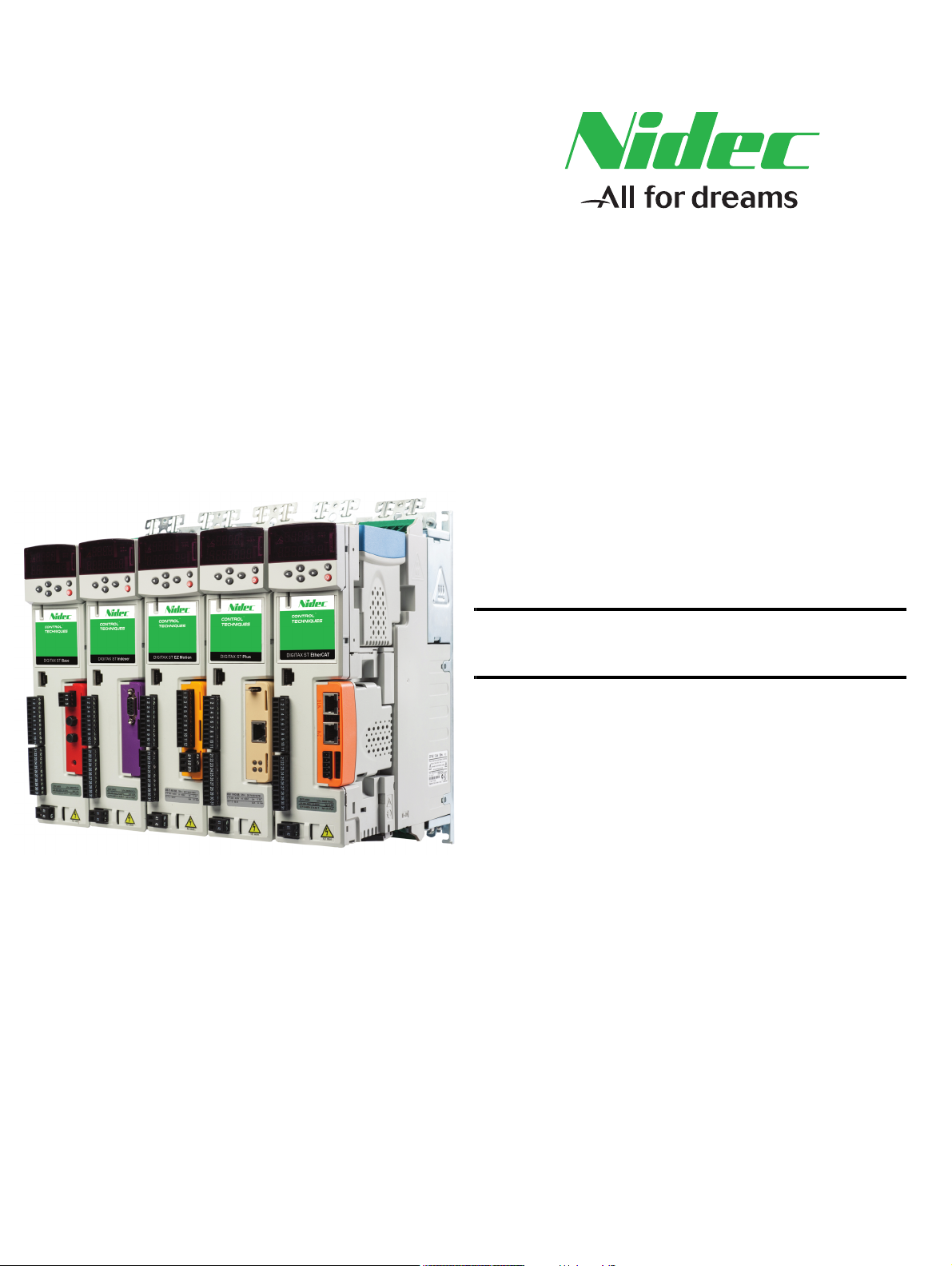
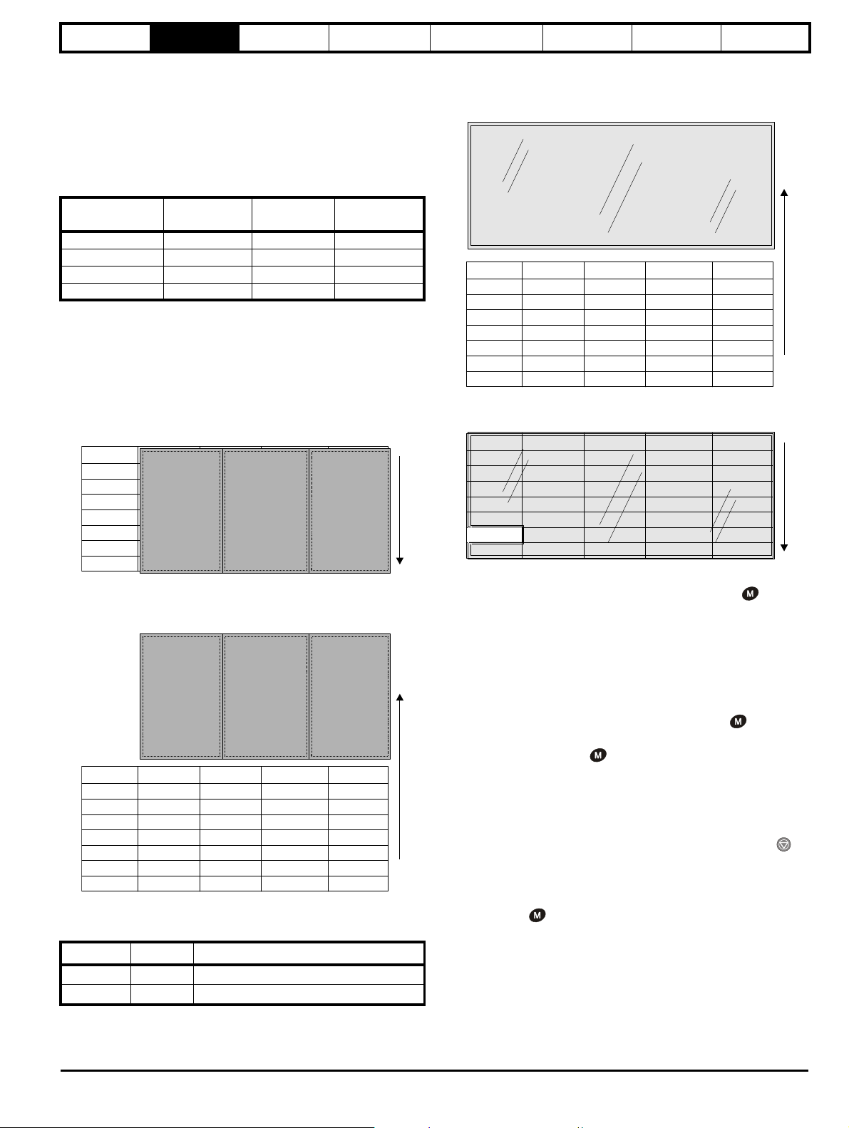
1 Parameter structure
The drive parameter structure consists of menus and parameters.
The drive initially powers up so that only menu 0 can be viewed. The up
and down arrow buttons are used to navigate between parameters and
once level 2 access (L2) has been enabled in Pr 0.49, and the left and
right buttons are used to navigate between menus. For further
information, see section 2.7 Parameter access level and security on
page 11.
Figure 1-1 Parameter navigation
* can only be used to move between menus if L2 access
has been enabled (Pr 0.49).
The menus and parameters roll over in both directions; i.e. if the last
parameter is displayed, a further press will cause the display to rollover
and show the first parameter.
When changing between menus the drive remembers which parameter
was last viewed in a particular menu and thus displays that parameter.
Figure 1-2 Menu structure
1.1 Menu 0
Menu 0 has up to 19 fixed parameters and 40 programmable parameters
that are defined in menu 11 and menu 22. Menu 0 parameters are
copies of advanced menu parameters, and although these parameters
are accessible via drive serial comms, they are not accessible to any
Solutions Modules. All menu 0 read/write parameters are saved on
exiting the edit mode. Table 1-1 gives the default structure for menu 0.
Where alternative parameters are selected with motor map 2 from menu
21 these are shown below the motor map 1 parameters.
Figure 1-3 Menu 0 copying
Menu 0 is used to bring together various commonly used parameters for
basic easy set up of the drive. All the parameters in menu 0 appear in
other menus in the drive (denoted by {…}).
Menus 11 and 22 can be used to change most of the parameters in
menu 0. Menu 0 can also contain up to 59 parameters by setting up
menu 22.
Digitax ST Advanced User Guide 5
Issue Number: 3
Page 6

Parameter
structure
Keypad and display Parameter x.00
Parameter description
format
Advanced parameter
descriptions
Serial comms
protocol
Electronic
nameplate
Performance
Table 1-1 Menu 0 parameters
Parameter
0.00 xx.00 {x.00} 0 to 32,767 0 RW Uni
0.01 Minimum reference clamp {1.07} ±SPEED_LIMIT_MAX rpm 0.0 RW Bi PT US
0.02 Maximum reference clamp {1.06} SPEED_LIMIT_MAX rpm 3,000.0 RW Uni
0.03 Acceleration rate
0.04 Deceleration rate {2.21}
0.05 Reference select {1.14}
0.06 Current limit {4.07} 0 to CURRENT_LIMIT_MAX % 300.0 RW Uni RA US
0.07 Speed controller P gain {3.10}
0.08 Speed controller I gain {3.11} 0.00 to 655.35 1/rad 1.00 RW Uni US
0.09 Speed controller D gain {3.12} 0.00000 to 0.65535 (s) 0.00000 RW Uni US
0.10 Motor speed {3.02} ±SPEED_MAX rpm
0.11 Drive encoder position {3.29}
0.12 Total motor current {4.01} 0 to Drive_current_max A
0.13
Analog input 1 offset trim
0.14 Torque mode selector {4.11} 0 to 4 Speed control mode (0) RW Uni US
0.15 Ramp mode select {2.04}
0.16 Ramp enable {2.02} OFF (0) or On (1) On (1) RW Bit US
Current demand filter time
0.17
constant
0.18 Positive logic select {8.29} OFF (0) or On (1) On (1) RW Bit PT US
0.19 Analog input 2 mode {7.11}
0.20 Analog input 2 destination {7.14}Pr 0.00 to Pr 21.51 Pr 1.37 RW Uni DE PT US
0.21 Analog input 3 mode {7.15}
0.22 Bipolar reference select {1.10} OFF (0) or On (1) OFF (0) RW Bit US
0.23 Jog reference {1.05} 0 to 4000.0 rpm 0.0 RW Uni US
0.24 Pre-set reference 1 {1.21} ±SPEED_LIMIT_MAX rpm 0.0 RW Bi US
0.25 Pre-set reference 2 {1.22} ±SPEED_LIMIT_MAX rpm 0.0 RW Bi US
0.26 Overspeed threshold {3.08} 0 to 40,000 rpm 0 RW Uni US
Drive encoder lines per
0.27
revolution
0.28 Keypad fwd/rev key enable {6.13} OFF (0) or On (1) OFF (0) RW Bit US
SMARTCARD parameter
0.29
data
0.30 Parameter copying {11.4 2} nonE (0), rEAd (1), Prog (2), AutO (3), boot (4) nonE (0) RW Txt NC *
0.31 Drive rated voltage {11.33} 200 (0), 400 (1)
0.32 Drive rated current {11.32} 0.00 to 9999.99A
0.34 User security code {11 .30}0 to 999 0 RWUniNCPTPS
0.35 Serial comms mode {11.24 } AnSI (0), rtu (1), Lcd (2) rtU (1) RW Txt US
0.36 Serial comms baud rate {11. 25}
0.37 Serial comms address {11 .23}0 to 247 1 RWUniUS
0.38 Current loop P gain {4.13} 0 to 30,000
0.39 Current loop I gain {4.14}
0.40 Autotune {5.12}0 to 6 0RWUni
Maximum switching
0.41
frequency
0.42 No. of motor poles {5.11} 0 to 60 (Auto to 120 pole) 6 POLE (3) RW Txt US
0.43 Encoder phase angle {3.25} 0.0 to 359.9° 0.0 RW Uni US
0.44 Motor rated voltage {5.09} 0 to AC_voltage_set_max V
0.45 Motor thermal time constant {4.15} 0.0 to 3000.0 20.0 RW Uni US
0.46 Motor rated current {5.07} 0 to Rated_current_max A Drive rated current [11. 32] RW Uni RA US
0.48 User drive mode {11.32 } SErVO (3) SErVO (3) RO Txt NC PT
0.49 Security status {11 .44} L1 (0), L2 (1), Loc (2)
0.50 Software version {11.29 } 1.00 to 99.99
0.51 Action on trip detection {10.37} 0 to 15 0 RW US
{2.11} 0.000 to 3,200.000
A1.A2 (0), A1.Pr (1), A2.Pr (2), Pr (3), PAd (4),
{7.07} ±10.000 % 0.000 RW Bi US
{4.12} 0.0 to 25.0 ms 0.0 RW Uni US
0-20 (0), 20-0 (1), 4-20tr (2), 20-4tr (3),
0-20 (0), 20-0 (1), 4-20tr (2), 20-4tr (3),
4-20 (4), 20-4 (5), VOLt (6), th.SC (7),
{3.34} 0 to 50,000 4096 RW Uni US
{11.36 } 0 to 999 0 RO Uni NC PT US
300 (0), 600 (1), 1200 (2), 2400 (3), 4800 (4),
{5.18} 3 (0), 4 (1), 6 (2), 8 (3), 12 (4) 6 (2) RW Txt RA US
Range(
Ú) Default(Ö)
s/1,000rpm
0.000 to 3,200.000
s/1,000rpm
Prc (5)
0.0000 to 6.5535 1/rad s
0 to 65,535
16
ths of a revolution
1/2
FASt (0)
Std ( 1)
4-20 (4), 20-4 (5), VOLt (6)
th (8), th.diSp (9)
9600 (5), 19200 (6), 38400 (7),
57600 (8) Modbus RTU only,
115200 (9) Modbus RTU only
0 to 30,000 200V drive: 1000
-1
0.200 RW Uni
0.200 RW Uni US
A1.A2 (0) RW Txt NC US
0.0100 RW Uni US
Std ( 1) RW Txt US
VOLt (6) RW Txt US
th (8) RW Txt PT US
19200 (6) RW Txt US
200V drive: 75
400V drive: 150
400V drive: 2000
200V drive: 230
400V drive: EUR> 400, USA> 460
RO Bi FI NC PT
RO Uni FI NC PT
RO Uni FI NC PT
RO Txt NC PT
RO Uni NC PT
RW Uni US
RW Uni US
RW Uni RA US
RW Txt PT US
RO Uni NC PT
Typ e
US
US
* Modes 1 and 2 are not user saved, modes 0, 3 and 4 are user saved
6 Digitax ST Advanced User Guide
Issue Number: 3
Page 7

Parameter
structure
Keypad and display Parameter x.00
Parameter description
format
Advanced parameter
descriptions
Serial comms
protocol
Table 1-2 Parameter type key 1.2 Advanced menus
Coding Attribute
{X.XX} Copied advanced parameter
RW Read/write: can be written by the user
RO Read only: can only be read by the user
Bit 1 bit parameter. ‘On’ or ‘OFF’ on the display
Bi Bipolar parameter
Uni Unipolar parameter
Txt Text: the parameter uses text strings instead of numbers.
Filtered: some parameters which can have rapidly changing
FI
values are filtered when displayed on the drive keypad for
easy viewing.
Destination: This parameter selects the destination of an
DE
input or logic function.
Rating dependent: this parameter is likely to have different
values and ranges with drives of different voltage and
current ratings. Parameters with this attribute will not be
RA
transferred to the destination drive by SMARTCARDs when
the rating of the destination drive is different from the
source drive and the file is a parameter file.
Not copied: not transferred to or from SMARTCARDs
NC
during copying.
PT Protected: cannot be used as a destination.
User save: parameter saved in drive EEPROM when the
US
user initiates a parameter save.
Power-down save: parameter automatically saved in drive
EEPROM when the under volts (UV) trip occurs.
PS
With software version V01.08.00 and later, power-down
save parameters are also saved in the drive when the user
initiates a parameter save.
The advanced menus consist of groups or parameters appropriate to a
specific function or feature of the drive. These are accessible via the
keypad, drive serial comms and Solutions Modules. All advanced menu
parameters are only saved by setting Pr x.00 to 1000 and applying a
reset (except parameters shown as power-down saved which are saved
automatically at power-down). The advanced menus are accessible
when the user selects L2 in Pr 11.44 (Pr 0.49 in menu 0). This can be
done even if security is programmed. Pr 11. 44 can be saved in
EEPROM so that either Menu 0 only, or Menu 0 and the advanced
menus are accessible at power-up.
Table 1-3 Digitax ST menus
Menu Function
1 Speed reference selection, limits and filters
2Ramps
3 Speed feedback and control
4 Current control
5 Motor control
6 Sequencer and clock
7 Analog I/O
8 Digital I/O
9 Programmable logic and motorized pot
10 Drive status and trip information
11 Miscellaneous
Programmable threshold, variable selector and brake control
12
function
13 Position control
14 User PID controller
15 Slot 1 Solutions Module menu
16 Slot 2 Solutions Module menu
17 Motion Processor
18 User application menu 1 (saved in drive EEPROM)
19 User application menu 2 (saved in drive EEPROM)
20 User application menu 3 (not saved in drive EEPROM)
21 Second motor map
22 Additional menu 0 set-up
Electronic
nameplate
Performance
1.3 Solutions Modules
Any Solutions Module type is recognized with all drive types in any slots.
The relevant template is used to define menu 15 for the module type
installed in slot 1 and menu 16 for slot 2. The slot 3 is enclosed within
Digitax ST and cannot be physically accessed by the user.
1.4 Drive software version
This product is supplied with the latest software version. If this drive is to
be connected to an existing system or machine, all drive software
versions should be verified to confirm the same functionality as drives of
the same model already present. This may also apply to drives returned
from a Control Techniques Service Centre or Repair Centre. If there is
any doubt please contact the supplier of the product.
The software version of the drive can be checked by looking at Pr 11.29
and Pr 11.34. This takes the form of xx.yy.zz where Pr 11.29 displays
xx.yy and Pr 11.34 displays zz. (e.g. for software version 01.01.00,
Pr 11.29 = 1.01 and Pr 11.34 displays 0).
Digitax ST Advanced User Guide 7
Issue Number: 3
Page 8
Parameter
WARNING
Upper display
Lower display
Mode (black) button
Programming buttons
Stop/reset (red) button
Mode (black) button
Joypad
Fwd / Rev (blue) button
Stop/reset (red) button
Start (green) button
Control buttons
Help button
NOTE
structure
Keypad and
display
Parameter x.00
Parameter description
format
Advanced parameter
descriptions
Serial comms
protocol
Electronic
nameplate
Performance
2 Keypad and display
Beware of possible live terminals when installing the keypad.
2.1 Understanding the display
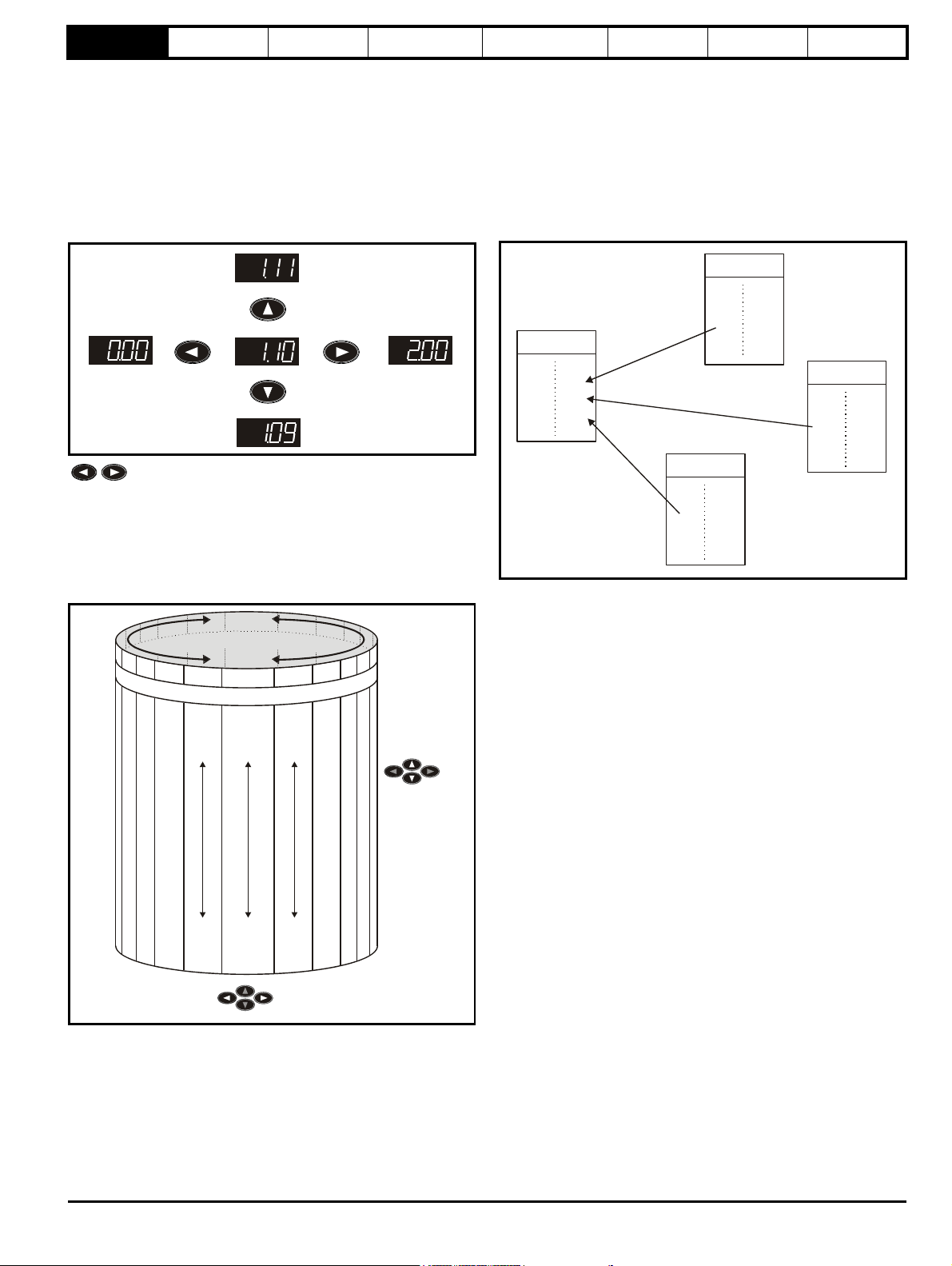
There are two keypads available for the Digitax ST. The Digitax ST Keypad has an LED display and the SM-Keypad Plus has an LCD display. The
Digitax ST Keypad can be installed to the drive and the SM-Keypad Plus is remotely mounted on an enclosure door.
2.1.1 Digitax ST Keypad (LED)
The display consists of two horizontal rows of 7 segment LED displays.
The upper display shows the drive status or the current menu and
parameter number being viewed.
The lower display shows the parameter value or the specific trip type.
Figure 2-1 Digitax ST Keypad Figure 2-2 SM-Keypad Plus (remote mount only)
2.1.2 SM-Keypad Plus
The display consists of three lines of text.
The top line shows the drive status or the current menu and parameter
number being viewed on the left, and the parameter value or the specific
trip type on the right.
The lower two lines show the parameter name or the help text.
Features :
• Parameter names displayed
• Units displayed (Hz, A, rpm, %)
• Parameter help text
• Diagnostics help text
• 5 language support: (English, French, German, Spanish and Italian)
• Displays SM-Applications virtual parameters: Menus 70 to 91
• Hardware key using the SM-Keypad Plus as a key to modify the
drive set-up
• User defined parameter set
• Browsing filter
• Adjustable contrast
The red stop button is also used to reset the drive.
2.2 Keypad operation
2.2.1 Control buttons
The keypad consists of:
1. Programming buttons: used to navigate the parameter structure and change parameter values.
2. Mode button: used to change between the display modes – parameter view, parameter edit, status.
3. Reset button
4. Help button (Keypad Plus only) - displays text briefly describing the selected parameter.
5. Start, Fwd/Rev buttons (Keypad Plus only) - used to control the drive if Keypad mode is selected.
The Help button toggles between other display modes and parameter help mode. The up and down functions on the joypad scroll the help text to
allow the whole string to be viewed. The right and left functions on the joypad have no function when help text is being viewed.
The display examples in this section show the DST-Keypad 7 segment LED display. The examples are the same for the SM-Keypad Plus except
that the information displayed on the lower row on the DST-Keypad is displayed on the right hand side of the top row on the SM-Keypad Plus.
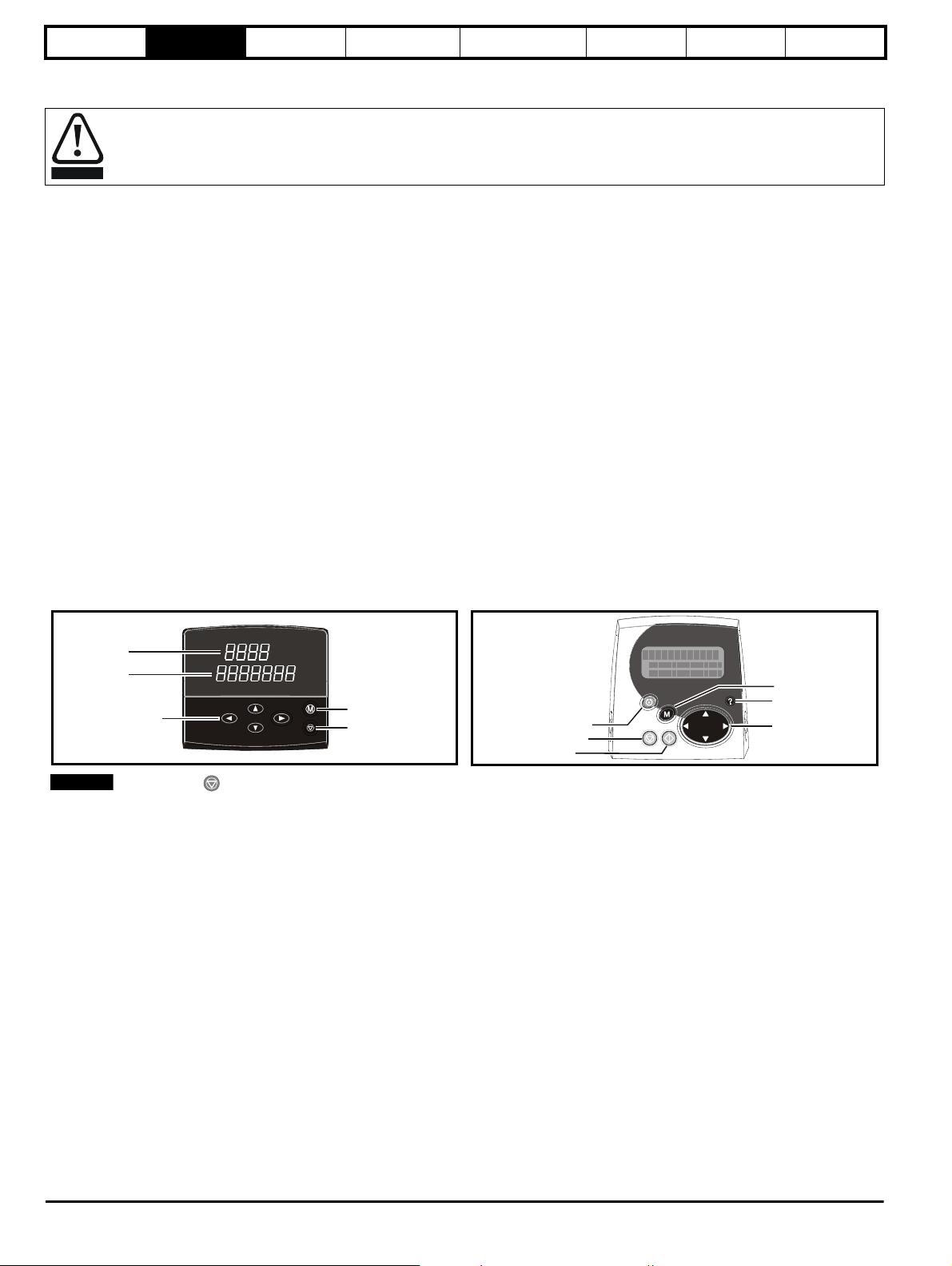
The drive parameters are accessed as shown in Figure 2-3.
8 Digitax ST Advanced User Guide
Issue Number: 3
Page 9
Parameter
Use
* keys
to select parameter for editing
To enter Edit Mode,
press key
Status
Mode
(Display
not
flashing)
Parameter
Mode
(Upper
display
flashing)
Edit Mode
(Character to be edited in lower line of display flashing)
Change parameter values
using keys.
When returning
to Parameter
Mode use the
keys to select
another parameter
to change, if
required
To exit Edit Mode,
press key
To enter Parameter
Mode, press key or
*
Temporary
Parameter
Mode
(Upper display
flashing)
Timeout**
Timeout**
Timeout**
To return to
Status Mode,
press
key
RO
parameter
R/W
parameter
structure
Keypad and
display
Figure 2-3 Display modes
Parameter x.00
Parameter description
format
Advanced parameter
descriptions
Serial comms
protocol
Electronic
nameplate
Performance
2.3 Status mode
In status mode the 1st row shows a four letter mnemonic indicating the
status of the drive. The second row show the parameter last viewed or
edited.
State
Inhibited: enable input is inactive inh
Ready: enable closed, but inverter not active rdY
Stopped: inverter active, but holding zero speed StoP
Running: inverter active and motor running run
Mains loss: decelerating to zero in mains loss ride-through or
stop modes
Decelerating: speed is ramping to zero after a stop dEC
Position: position control active during orientation stop POS
Tripped: drive is tripped triP
2.4 Parameter view mode
In this mode the 1st row shows the menu.parameter number and the 2nd
row the parameter value. The 2nd row gives a parameter value range of
-999,999 to 9,999,999 with or without decimal points. (32 bit parameters
can have values outside this range if written by an application module. If
the value is outside this range “-------“ is shown and the parameter value
cannot be changed from the keypad.) The Up and Down keys are used
to select the parameter and the Left and Right keys are used to select
the menu. In this mode the Up and Down keys are used to select the
parameter within the selected menu. Holding the Up key will cause the
parameter number to increment until the top of the menu is reached. A
single Up key action when the last parameter in a menu is being
displayed will cause the parameter number to roll over to Pr x.00.
Digitax ST Advanced User Guide 9
Issue Number: 3
*Can only be used to move between menus if L2 access has been enabled (Pr 0.49). Refer to section 2.7 Parameter access level
and security on page 11.
**Timeout defined by Pr 11.4 1 (default value = 240 s).
Similarly holding the Down key will cause the parameter number to
decrement until Pr x.00 is reached and a single Down key action will
cause the parameter number to roll under to the top of the menu.
Pressing the Up and Down keys simultaneously will select Pr x.00 in the
currently selected menu.
Upper
row
The Left and Right keys are used to select the required menu (provided
the security has been unlocked to allow access to menus other than 0).
Holding the Right key will cause the menu number to increment until the
Menu 22 is reached. A single Right key action when Menu 22 is being
displayed will cause the menu number to roll over to 0. Similarly holding
the Left key will cause the menu number to decrement to 0 and a single
key action will cause the menu number to roll under to Menu 22.
Pressing the Left and Right keys simultaneously will select Menu 0.
The drive remembers the parameter last accessed in each menu such
that when a new menu is entered the last parameter viewed in that menu
will re-appear.
2.5 Edit mode
Up and Down keys are used to increase and decrease parameter values
respectively. If the maximum value of a parameter is greater than 9 and it
is not represented by strings, then the Left and Right keys can be used
to select a digit to adjust. The number of digits which can be
independently selected for adjustment depends on the maximum value
of the parameter. Pressing the Right key when the least significant digit
ACUU
is selected will cause the most significant digit to be selected, and viceversa if the Left key is pressed when the most significant digit is
selected. When a digit value is not being changed by the Up or Down
keys the selected digit flashes to indicate which one is currently
selected. For string type parameters the whole string flashes when
adjustment is not occurring because there is no digit selection.
During adjustment of a parameter value with the Up or Down keys the
display does not flash, providing the parameter value is in range, such
Page 10

Parameter
structure
that the user can see the value being edited without interruption.
Adjustment of a numerical value can be done in one of two ways; firstly
by using the Up and Down keys only, the selected digit remaining the
least significant digit; and secondly by selecting each digit in turn and
adjusting them to the required value. Holding the Up or Down key in the
first method will cause the parameters value to change more rapidly the
longer the key is held, until such time that the parameters maximum or
minimum is reached. However with the second method an increasing
rate of change does not take place when adjusting any other digit other
than the least significant digit since a digit can only have one of 10
different values. Holding the Up or Down will cause an auto repeat and
roll over to more significant digits but the rate of change is unaltered. If
the maximum or minimum is exceeded when adjusting any other digit
than the least significant one, the maximum value will flash on the
display to warn the user that the maximum or minimum has been
reached. If the user releases the Up or Down key before the flashing
stops the last in range value will re-appear on the display. If the Up or
Keypad and
display
Parameter x.00
Parameter description
format
Advanced parameter
descriptions
Serial comms
protocol
Electronic
nameplate
Down key is held the display will stop flashing after 3 seconds and the
maximum value will be written to the parameter.
Parameters can be set to 0 by pressing the Up and Down keys
simultaneously.
2.6 SM-Keypad Plus
All SM-Keypad Plus displays built after data code N10 have software
version 4.02.00 programmed and support 5 languages (English, French,
German, Spanish and Italian) in addition to a user defined parameter set.
This software also gives the user access to two menus for SM-Keypad
Plus. Menu 40 is for SM-Keypad Plus set up, menu 41 selects commonly
used parameters for quick browsing.
Keypads built prior to N10 only support one user defined extra
parameter set only.
The SM-Keypad Plus contains two menus, menu 40 and menu 41. The
parameters in these menus are listed below.
Table 2-1 Menu 40 parameter descriptions
Parameter
Range(
Ú) Default(Ö)
40.00 Parameter 0 0 to 32767 0 RW Uni
English (0), Custom (1),
40.01 Language selection
French (2), German (3),
English (0) RW Txt US
Spanish (4), Italian (5)
40.02 Software version
40.03 Save to flash
40.04 LCD contrast
Drive and attribute database upload was
40.05
bypassed
Idle (0), Save (1), Restore (2),
999999 RO Uni PT
Default (3)
Idle (0) RW Txt
0 to 31 16 RW Uni US
Updated (0), Bypass (1) RO Txt PT
40.06 Browsing favourites control Normal (0), Filter (1) Normal (0) RW Txt
40.07 Keypad security code
40.08 Communication channel selection
40.09 Hardware key code
40.10 Drive node ID (Address)
40.11 Flash ROM memory size
40.19 String database version number
40.20 Screen saver strings and enable
40.21 Screen saver interval
40.22 Turbo browse time interval
Disable (0), Slot1 (1), Slot2 (2),
Slot3 (3), Slave (4), Direct (5)
None (0), Default (1), User (2) Default (1) RW Txt US
0 to 999 0RWUniUS
Disable (0) RW Txt US
0 to 999 0RWUniUS
0 to 255 1RWUniUS
4Mbit (0), 8Mbit (1) RO Txt PT US
0 to 999999 RO Uni PT
0 to 600 120 RW Uni US
0 to 200ms 50ms RW Uni US
Performance
Typ e
Table 2-2 Menu 41 parameter descriptions
Parameter
Range(
Ú) Default(Ö)
Typ e
41.00 Parameter 0 0 to 32767 0 RW Uni
41.01
to
Browsing filter source F01 to F50 Pr 0.00 to Pr 391.51 0RWUni
41.50
41.51 Browsing favourites control Normal (0), Filter (1) Normal (0) RW Txt
RW Read / Write RO Read only Uni Unipolar Bi Bi-polar
Bit Bit parameter Txt Text string FI Filtered DE Destination
NC Not copied RA Rating dependent PT Protected US User save
PS Power down save
For more information about the SM-Keypad Plus, see the SM-Keypad Plus User Guide.
10 Digitax ST Advanced User Guide
Issue Number: 3
Page 11
Parameter
Pr 0.00
Pr 0.01
Pr 0.02
Pr 0.03
Pr 0.49
Pr 0.50
Pr 1.00
Pr 1.01
Pr 1.02
Pr 1.03
Pr 1.49
Pr 1.50
Pr 22.00
Pr 22.01
Pr 22.02
Pr 22.03
Pr 22.28
Pr 22.29
............
............
............
............
............
............
............
............
L2 access selected
- All parameters visible
Pr 0.00
Pr 0.01
Pr 0.02
Pr 0.03
Pr 0.49
Pr 0.50
Pr 1.00
Pr 1.01
Pr 1.02
Pr 1.03
Pr 1.49
Pr 1.50
Pr 19.00
Pr 19.01
Pr 19.02
Pr 19.03
Pr 19.49
Pr 19.50
Pr 20.00
Pr 20.01
Pr 20.02
Pr 20.03
Pr 20.49
Pr 20.50
............
............
............
............
............
............
............
............
L1 access selected
- Menu 0 only visible
Pr 21.00
Pr 21.01
Pr 21.02
Pr 21.03
Pr 21.30
Pr 21.31
Pr 0.00
Pr 0.01
Pr 0.02
Pr 0.03
Pr 0.50
Pr 1.00
Pr 1.01
Pr 1.02
Pr 1.03
Pr 1.49
Pr 1.50
............
............
............
............
............
............
............
............
Pr 0.00
Pr 0.01
Pr 0.02
Pr 0.03
Pr 0.49
Pr 0.50
Pr 1.00
Pr 1.01
Pr 1.02
Pr 1.03
Pr 1.49
Pr 1.50
Pr 22.00
Pr 22.01
Pr 22.02
Pr 22.03
Pr 22.28
Pr 22.29
............
............
............
............
............
............
............
............
User security open
- All parameters: Read / Write access
User security closed
0.49 11.44
- All parameters: Read Only access
(except Pr and Pr )
Pr 22.00
Pr 22.01
Pr 22.02
Pr 22.03
Pr 22.28
Pr 22.29
Pr 0.49
Pr 21.00
Pr 21.01
Pr 21.02
Pr 21.03
Pr 21.30
Pr 21.31
Pr 21.00
Pr 21.01
Pr 21.02
Pr 21.03
Pr 21.30
Pr 21.31
structure
Keypad and
display
Parameter x.00
Parameter description
format
Advanced parameter
descriptions
Serial comms
protocol
Electronic
nameplate
Performance
2.7 Parameter access level and security
The parameter access level determines whether the user has access to
menu 0 only or to all the advanced menus (menus 1 to 22) in addition to
menu 0.
The User Security determines whether the access to the user is read
only or read write.
Both the User Security and Parameter Access Level can operate
independently of each other as shown in the table below:
Parameter
Access Level
User Security
Menu 0
status
L1 Open RW Not visible
L1 Closed RO Not visible
L2 Open RW RW
L2 Closed RO RO
RW = Read / write access RO = Read only access
The default settings of the drive are Parameter Access Level L1 and
user Security Open, i.e. read / write access to Menu 0 with the advanced
menus not visible.
2.7.1 Access Level
The access level is set in Pr 0.49 and allows or prevents access to the
advanced menu parameters.
Advanced
menus status
2.7.3 User Security
The User Security, when set, prevents write access to any of the
parameters (other than Pr. 0.49 Access Level) in any menu.
2.7.2 Changing the Access Level
The Access Level is determined by the setting of Pr 0.49 as follows:
String Value Effect
L1 0 Access to menu 0 only
L2 1 Access to all menus (menu 0 to menu 22)
The Access Level can be changed through the keypad even if the User
Security has been set.
Digitax ST Advanced User Guide 11
Issue Number: 3
Setting User Security
Enter a value between 1 and 999 in Pr 0.34 and press the button;
the security code has now been set to this value. In order to activate the
security, the Access level must be set to Loc in Pr 0.49. When the drive
is reset, the security code will have been activated and the drive returns
to Access Level L1. The value of Pr 0.34 will return to 0 in order to hide
the security code. At this point, the only parameter that can be changed
by the user is the Access Level Pr 0.49.
Unlocking User Security
Select a read write parameter to be edited and press the button, the
upper display will now show CodE. Use the arrow buttons to set the
security code and press the button.
With the correct security code entered, the display will revert to the
parameter selected in edit mode.
If an incorrect security code is entered the display will revert to
parameter view mode.
To lock the User Security again, set Pr 0.49 to Loc and press the
reset button.
Disabling User Security.
Unlock the previously set security code as detailed above. Set Pr 0.34 to
0 and press the button. The User Security has now been disabled,
and will not have to be unlocked each time the drive is powered up to
allow read / write access to the parameters.
Page 12

Parameter
structure
Keypad and
display
Parameter x.00
Parameter description
format
Advanced parameter
descriptions
Serial comms
protocol
Electronic
nameplate
Performance
2.8 Alarm and trip display
An alarm can flash alternately with the data displayed on the 2nd row
when one of the following conditions occur. If action is not taken to
eliminate the alarm, except "Auto tunE", "Lt" and "PLC", the drive may
eventually trip. Alarms flash once every 640ms except "PLC" which
flashes once every 10s. Alarms are not displayed when a parameter is
being edited.
Alarm string Alarm condition
br.rS
OVLd
hot Heatsink or control board alarms are active
Auto tunE Auto tune in progress
Lt
PLC On-board PLC program is running
When a trip occurs the drive switches to status mode and "trip" is shown
on the 1st row and the trip string flashes on the 2nd row. The read only
parameters listed below are frozen with any trip except UV trip until the
trip is cleared. For a list of the possible trip strings see Pr 10.20.
Pressing any of the parameter keys changes the mode to the parameter
view mode. If the trip is HF01 to HF16 then no key action is recognized.
Parameter Description
1.01 Speed reference
1.02 Speed reference
1.03 Pre-ramp reference
2.01 Post-ramp reference
3.01 Final speed reference
3.02 Speed feedback
3.03 Speed error
3.04 Speed controller output
4.01 Current magnitude
4.02 Active current
4.17 Magnetising current
5.01 Output frequency
5.02 Output voltage
5.03 Power
5.05 DC bus voltage
7.01 Analog input 1
7.02 Analog input 2
7.03 Analog input 3
Braking resistor (Pr 10.39 > 75.0% and the
braking IGBT is active)
Motor overload (Pr 4.20 > 75% and the drive
output current > Pr 5.07)
Indicates that a limit switch is active and that it is
causing the motor to be stopped (i.e. forward
limit switch with forward reference etc.)
2.9 Keypad control mode (SM-Keypad Plus only)
The drive can be controlled from the keypad if Pr 1.14 is set to 4. The
Stop and Run keys automatically become active (the Reverse key may
be optionally enabled with Pr 6.13). The speed reference is defined by
Pr 1.17. This is a read only parameter that can only be adjusted in status
mode by pressing the Up or Down keys. If keypad control mode is
selected, then pressing the Up or Down keys in status mode will cause
the drive to automatically display the keypad reference and adjust it in
the relevant direction. This can be done whether the drive is disabled or
running. If the Up or Down keys are held the rate of change of keypad
reference increases with time. The units used for to display the keypad
reference is rpm.
2.10 Drive reset
A drive reset is required to: reset the drive from a trip (except some
“HFxx” trips which cannot be reset); and other functions as defined in
section 3 Parameter x.00 on page 13. A reset can be performed in four
ways:
1. Stop key: If the drive has been set up such that the stop key is not
operative then the key has a drive reset function only. When the stop
function of the stop key is enabled, a reset is initiated while the drive
is running by holding the Run key and then pressing the Stop key.
When the drive is not running the Stop key will always reset the
drive.
2. The drive resets after a 0 to 1 transition of the Drive Reset parameter
(Pr 10.33). A digital input can be programmed to change this
parameter.
3. Serial comms, fieldbus or applications Solutions Module: Drive reset
is triggered by a value of 100 being written to the User trip parameter
(Pr 10.38).
4. Auto-reset: Pr 10.34 can be used to provide an auto-reset function.
If the drive trips EEF (internal EEPROM error) then it is not possible to
reset the drive using the normal reset methods described above. 1233 or
1244 must be entered into Pr x.00 before the drive can be reset. Default
parameters are loaded after an EEF trip, and so the parameters should
be reprogrammed as required and saved in EEPROM.
If the drive is reset after a trip from any source other than the Stop key,
the drive restarts immediately, if:
1. A non-latching sequencer is used with the enable active and one of
run forward, run reverse or run active
2. A latching sequencer is used if the enable and “not stop” are active
and one of run forward, run reverse or run is active.
If the drive is reset with the Stop key the drive does not restart until a not
active to active edge occurs on run forward, run reverse or run.
2.11 Second motor parameters
An alternative set of motor parameters are held in menu 21 which can be
selected by Pr 11.45 . When the alternative parameter set is being used
by the drive the decimal point after the right hand digit in the 1st row is
on.
2.12 Special display functions
The following special display functions are used.
1. If the second motor map is being used the decimal point second
from the right of the first row is on.
2. When parameters are saved to a SMARTCARD the right-most
decimal point on the first row flashes for 2 seconds.
During power up one or more of the following actions may be required.
Each action may take several seconds, and so special display strings
are shown.
Display
string
loading
Action
If a SMARTCARD is present with Pr 11.42 set to boot the
boot
parameters from the card must be transferred to the drive
EEPROM.
If the drive is in auto or boot mode (Pr 11.42 set to 3 or 4) the
card
drive ensures that the data on the card is consistent with the
drive by writing to the card.
It may be necessary for a Solutions Module to transfer
parameter information from the drive. This is only carried out
if the parameter information held by the Solutions Module is
for a different drive software version. The drive allows up to 5
seconds for this process.
12 Digitax ST Advanced User Guide
Issue Number: 3
Page 13

Parameter
structure
Keypad and display
Parameter x.00
Parameter description
format
Advanced parameter
descriptions
Serial comms
protocol
Electronic
nameplate
Performance
3 Parameter x.00
Parameter x.00 is available in all menus and has the following functions.
Value Action
1000
1001 Save parameters under all conditions
1070 Reset all Solutions Modules
1233 Load standard defaults
1244 Load US defaults
2001
3yyy
4yyy
5yyy
6yyy Transfer SMARTCARD data block yyy to the drive
7yyy Erase SMARTCARD data block yyy
8yyy Compare drive parameters with block yyy
9555 Clear SMARTCARD warning suppression flag
9666 Set SMARTCARD warning suppression flag
9777 Clear SMARTCARD read-only flag
9888 Set SMARTCARD read-only flag
9999 Erase SMARTCARD
110zy
*12000 Display non-default values only
*12001 Display destination parameters only
*These functions do not require a drive reset to become active. All other
functions require a drive reset.
3.1 Parameter x.00 reset
When an action is started by setting Pr x.00 to one of the above values
and initiating a drive reset this parameter is cleared when the action is
completed successfully. If the action is not started, e.g. because the
drive is enabled and an attempt is made to load defaults, etc., Pr x.00 is
not cleared and no trip is produced. If the action is started and then fails
for some reason a trip is always produced and Pr x.00 is not cleared. It
should be noted that parameter saves etc. can also be initiated with the
copying parameter (Pr 11. 42). If actions that can be initiated by either
parameter are started and then completed successfully Pr x.00 is
cleared and Pr 11.42 is cleared if it has a value of less than 3.
It should be noted that there could be some conflict between the actions
of Pr x.00 and Pr 11.42 (Parameter copying) when the drive is reset. If
Pr 11.42 has a value of 1 or 2 and a valid action is required from the
value of Pr x.00 then only the action required by Pr x.00 is performed.
Pr x.00 and Pr 11.42 are then reset to zero. If Pr 11.4 2 has a value of 3
or 4 it will operate correctly causing parameters to be save to a
SMARTCARD each time a parameter save is performed.
Save parameters when under voltage is not active
(Pr 10.16 = 0) and 48V supply is not active (Pr 6.44 = 0).
Transfer drive parameter to a card and create a bootable
difference from default SMARTCARD block with data
block number 1 and clear Pr 11.42 . If data block 1 exists
it is over written.
Transfer drive EEPROM data to a SMARTCARD block
number yyy
Transfer drive data as difference from defaults to
SMARTCARD block number yyy
Transfer drive ladder program to SMARTCARD block
number yyy
Transfer electronic nameplate parameters to/from drive
from/to encoder
3.2 Saving parameters in drive EEPROM
Drive parameters are saved to drive EEPROM by setting Pr x.00 to 1000
or 1001 and initiating a drive reset. In addition to user save parameters,
power down save parameters are also saved by these actions, but not
by any other actions that result in parameters being saved to drive
EEPROM (i.e. loading defaults). Power down save parameters are not
saved at power down unless the drive is supplied from a normal line
power supply, and so this gives the user the option of saving these
parameters when required. When the parameter save is complete
Pr x.00 is reset to zero by the drive. Care should be taken when saving
parameters because this action can take between 400ms and several
seconds depending on how many changes are stored in the EEPROM. If
the drive is powered down during a parameter save it is possible that
data may be lost. When the drive is operating from a normal line power
supply then it will stay active for a short time after the power is removed,
however, if the drive is being powered from a 24V control supply, or it is
being operated from a low voltage battery supply, the drive will power
down very quickly after the supply is removed. The drive provides two
features to reduce the risk of data loss when the drive is powered down.
1. If Pr x.00 is set to 1000 a parameter save is only initiated on drive
reset if the drive is supplied from a normal line power supply
(Pr 10.16 = 0 and Pr 6.44 = 0). 1001 must be used to initiate a save
if the drive is not supplied from a normal line power supply.
2. Two banks of arrays are provided in EEPROM to store the data.
When a parameter save is initiated the data is stored in a new bank
and only when the data store is complete does the new bank
become active. If the power is removed before the parameter save is
complete a SAVE.Er trip (user save parameter save error) or
PSAVE.Er trip (power down save parameter save error) will be
produced when the drive is powered up again indicating that the
drive has reverted to the data that was saved prior to the last
parameter save.
The second feature will significantly reduce the possibility of completely
invalidating all saved data, which would result in an EEF trip on the next
power-up. However the following points should be noted:
1. If the power is removed during a parameter save the current data
that is being saved to the EEPROM that is different from the last
data saved in the EEPROM will be lost and SAVE.Er or PSAVE.Er
trip will occur on power-up.
2. This feature does not apply when user save parameters are saved
automatically by adjusting the values in menu 0 with an LED keypad.
However, the time taken to save parameters in this way is very short,
and is unlikely to cause data loss if the power is removed after the
parameter has been changed. It should be noted that any parameter
changes made in this way are included in the currently active bank in
the EEPROM, so that if the power is removed during a subsequent
save initiated via Pr x.00 that results in an SAVE.Er trip, the changes
made via menu 0 will be retained and not lost.
3. User save parameters are saved to drive EEPROM after a transfer
of data from an electronic nameplate in an encoder.
4. User save parameters are saved to drive EEPROM after a transfer
of data from a SMARTCARD.
5. This feature is not provided for data saved to a SMARTCARD, and
so it is possible to corrupt the data files on a SMARTCARD if the
power is removed when data is being transferred to the card.
6. User save parameters are saved to drive EEPROM after defaults
are loaded.
7. When a Solutions Module is changed for a different type in a slot, or
a module is inserted when one was not present previously or a
module is removed the EEPROM is forced to re-initialise itself on the
next parameter saves. On the first parameter save one bank is
cleared and then written and on the next parameter save the other
bank is cleared and rewritten. Each of these parameter saves takes
slightly longer than a normal parameter save.
8. When the firmware is updated from an earlier version the drive will
automatically update the EEPROM correctly. If the software is
Digitax ST Advanced User Guide 13
Issue Number: 3
Page 14
Parameter
structure
changed back to an earlier version defaults should be loaded after
the change.
Keypad and display
Parameter x.00
Parameter description
format
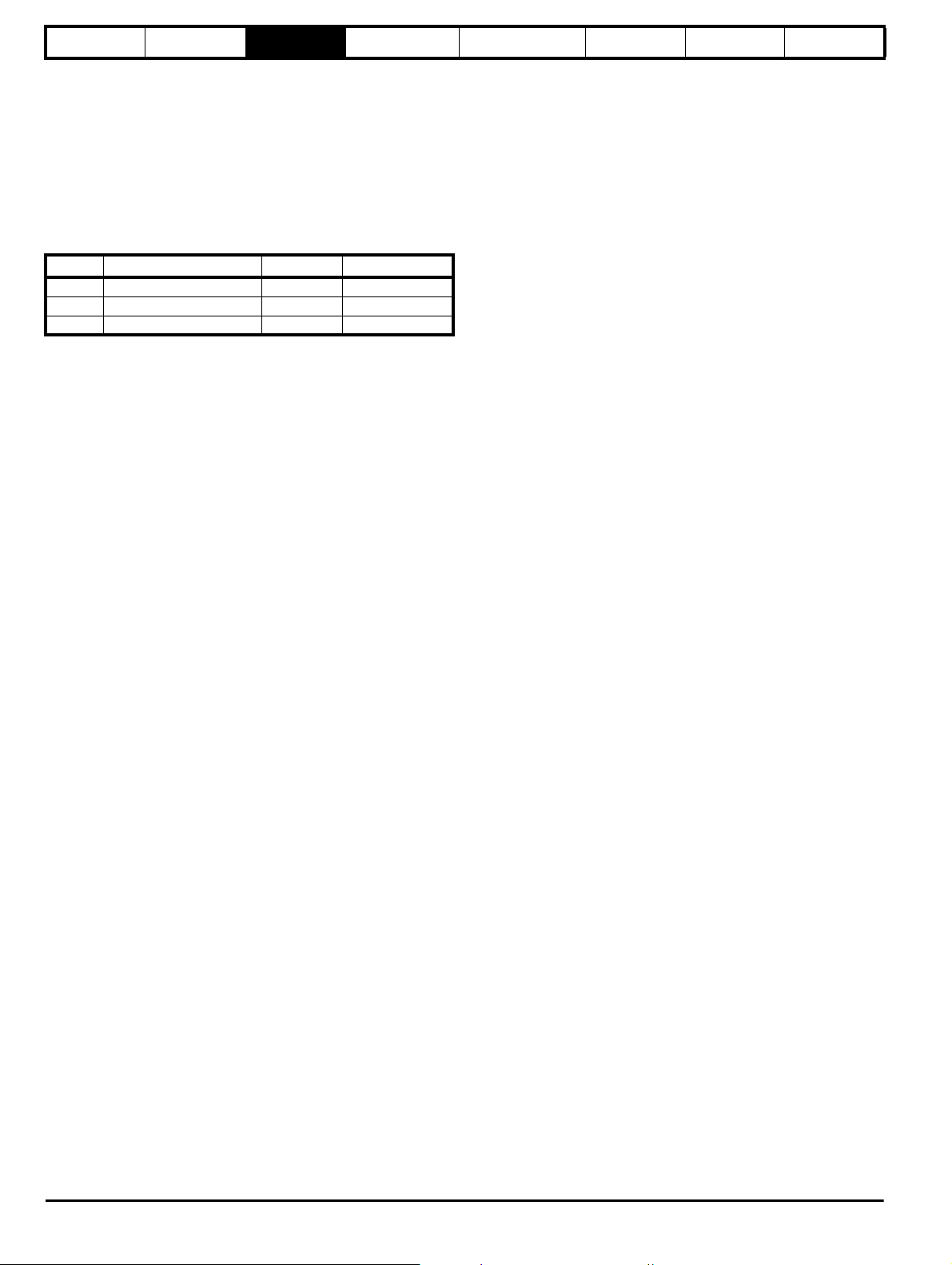
3.3 Loading defaults
When defaults are loaded the user save parameters are automatically
saved to the drive EEPROM in all modes. Standard defaults are loaded
by setting 1233 in Pr x.00 performing a drive reset.
The following differences from standard defaults are available when
different values are set in Pr x.00.
US Default Differences (Pr x.00 = 1244 and perform a drive reset)
Pr Description Default Voltage rating
2.08 Standard ramp volts 775V 400V
5.09 Rated voltage 460V 400V
21.09 M2 Rated voltage 460V 400V
3.4 SMARTCARD transfers
Drive parameters, set-up macros and internal ladder programs can be
transferred to/from SMARTCARDs. See Pr 11.36 to Pr 11.4 0.
3.5 Electronic nameplate transfers
Some encoders using Stegmann Hiperface or EnDat comms can hold
motor data. The data can be transferred to/from the encoder by writing
110zy to parameter x.00 and resetting the drive where z is 0 for the drive
or 1, 2 or 3 for Solutions Module slots 1, 2 or 3 respectively. See Chapter
7 Electronic nameplate on page 216 for details.
Advanced parameter
descriptions
Serial comms
protocol
Electronic
nameplate
Performance
3.6 Display non-default values or destination parameters
If a value of 12000 is written to Pr x.00, then only parameters that are
different from the last defaults loaded and Pr x.00 are displayed. If a
value of 12001 is written to Pr x.00, then only destination parameters are
displayed. This function is provided to aid locating destination clashes if
a dESt trip occurs.
14 Digitax ST Advanced User Guide
Issue Number: 3
Page 15

Parameter
NOTE
structure
Keypad and
display
Parameter x.00
Parameter description
format
Advanced parameter
descriptions
Serial comms
protocol
Electronic
nameplate
Performance
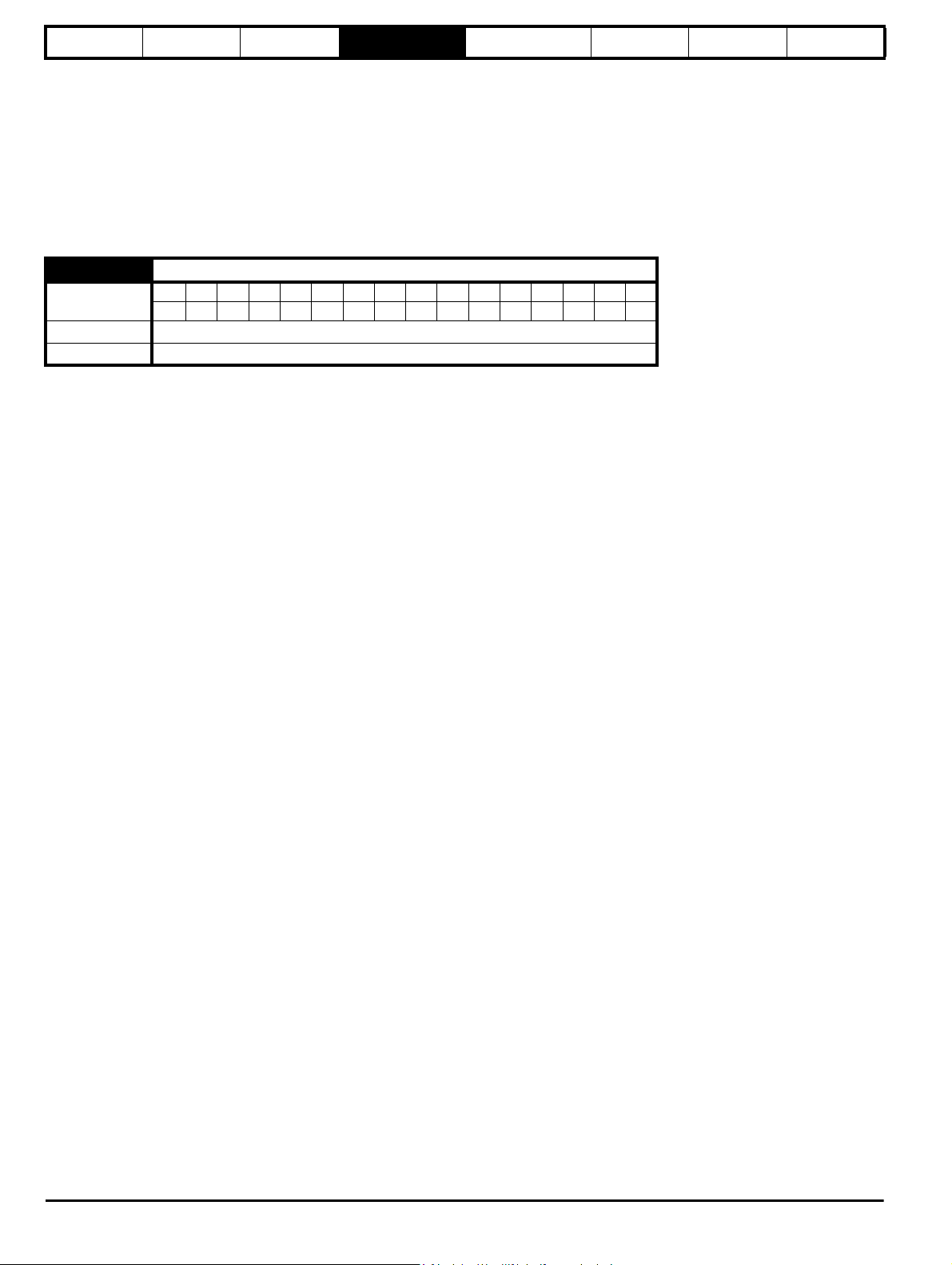
4 Parameter description format
In the following sections descriptions are given for the advanced parameter set. With each parameter the following information block is given.
5.11 Number of motor poles
Coding
Range 0 to 60 (Auto to 120 POLE)
Default 3 (6 POLE)
Second motor
parameter
Update rate
The top row gives the menu.parameter number and the parameter name. The other rows give the following information.
Coding
This guide will show all bit parameters (with the Bit coding), as having a parameter range of "0 to 1", and a default value of either "0" or "1". This
reflects the value seen through serial communications. The bit parameters will be displayed on the DST-Keypad or SM-Keypad Plus (if used) as being
"OFF" or "On" ("OFF"= 0, "On" = 1).
The coding defines the attributes of the parameter as follows:
Coding Attribute
RW Read/write: can be written by the user
RO Read only: can only be read by the user
Bit 1 bit parameter. ‘On’ or ‘OFF’ on the display
Bi Bipolar parameter
Uni Unipolar parameter
Txt Text: the parameter uses text strings instead of numbers.
FI
DE
RA
NC
PT Protected: cannot be used as a destination.
US
PS
Bit SP FI DE Txt VM DP ND RA NC NV PT US RW BU PS
1111
Pr 21.11
Background read
Filtered: some parameters which can have rapidly changing
values are filtered when displayed on the drive keypad for
easy viewing.
Destination: This parameter selects the destination of an
input or logic function.
Rating dependent: this parameter is likely to have different
values and ranges with drives of different voltage and
current ratings. Parameters with this attribute will not be
transferred to the destination drive by SMARTCARDs when
the rating of the destination drive is different from the
source drive and the file is a parameter file.
Not copied: not transferred to or from SMARTCARDs
during copying.
User save: parameter saved in drive EEPROM when the
user initiates a parameter save.
Power-down save: parameter automatically saved in drive
EEPROM when the under volts (UV) trip occurs.
With software version V01.08.00 and later, power-down
save parameters are also saved in the drive when the user
initiates a parameter save.
Digitax ST Advanced User Guide 15
Issue Number: 3
Page 16

Parameter
Maximum
current limit
=
[
Maximum current
]
x 100%
Motor rated current
structure
Keypad and
display
Parameter x.00
Parameter description
format
Advanced parameter
4.1 Parameter ranges and variable maximums:
The two values provided define the minimum and maximum values for
the given parameter. In some cases the parameter range is variable and
dependant on either:
• other parameters,
• the drive rating,
• or a combination of these.
The values given in Table 4-1 are the variable maximums used in the
drive.
Table 4-1 Definition of parameter ranges & variable maximums
Maximum Definition
Maximum speed reference
SPEED_REF_MAX
[40000.0rpm]
SPEED_LIMIT_MAX
[40000.0rpm]
SPEED_MAX
[40000.0rpm]
DRIVE_CURRENT_MAX
[9999.99A]
AC_VOLTAGE_SET_MAX
[690V]
AC_VOLTAGE_MAX
[930V]
DC_VOLTAGE_SET_MAX
[1150V]
DC_VOLTAGE_MAX
[1190V]
MOTOR1_CURRENT_LIMIT_MAX
[1000.0%]
MOTOR2_CURRENT_LIMIT_MAX
[1000.0%]
If Pr 1.08 = 0: SPEED_REF_MAX = Pr 1.06
If Pr 1.08 = 1: SPEED_REF_MAX is Pr 1.06 or – Pr 1.07 whichever is the largest
(If the second motor map is selected Pr 21.01 is used instead of Pr 1.06 and Pr 21.02 instead of Pr 1.07)
Maximum applied to speed reference limits
A maximum limit may be applied to the speed reference to prevent the nominal encoder frequency from
exceeding 500kHz. The maximum is defined by
SPEED_LIMIT_MAX (in rpm) = 500kHz x 60 / ELPR = 3.0 x 10
40,000 rpm.
ELPR is equivalent encoder lines per revolution and is the number of lines that would be produced by a
quadrature encoder.
Quadrature encoder ELPR = number of lines per revolution
F and D encoder ELPR = number of lines per revolution / 2
Resolver ELPR = resolution / 4
SINCOS encoder ELPR = number of sine waves per revolution
Serial comms encoder ELPR = resolution / 4
This maximum is defined by the device selected with the speed feedback selector (Pr 3.26) and the ELPR set
for the position feedback device.
Maximum speed
This maximum is used for some speed related parameters in menu 3. To allow headroom for overshoot etc. the
maximum speed is twice the maximum speed reference.
SPEED_MAX = 2 x SPEED_REF_MAX
Maximum drive current
The maximum drive current is the current at the over current trip level and is given by:
DRIVE_CURRENT_MAX = K
Maximum output voltage set-point
Defines the maximum motor voltage that can be selected.
200V drives: 240V, 400V drives: 480V
Maximum AC output voltage
This maximum has been chosen to allow for maximum AC voltage that can be produced by the drive including
quasi-square wave operation as follows:
AC_VOLTAGE_MAX = 0.78 x DC_VOLTAGE_MAX
200V drives: 325V, 400V drives: 650V
Maximum DC voltage set-point
200V rating drive: 0 to 400V, 400V rating drive: 0 to 800V
Maximum DC bus voltage
The maximum measurable DC bus voltage.
200V drives: 415V, 400V drives: 830V
Maximum current limit setting for motor map 1
The maximum current limit setting is the maximum applied to the current limit parameters in motor map 1.
Where:
The Maximum current is (1.75 x
Motor rated current is given by Pr 5.07
Maximum current limit settings for motor map 2
This maximum current limit setting is the maximum applied to the current limit parameters in motor map 2.
The formulae for MOTOR2_CURRENT_LIMIT_MAX are the same for MOTOR1_CURRENT_LIMIT_MAX
except that Pr 5.07 is replaced with Pr 21.07 and Pr 5.10 is replaced with Pr 21.10.
/ 0.45
C
KC).
descriptions
Serial comms
protocol
7
/ ELPR subject to an absolute maximum of
Electronic
nameplate
Performance
16 Digitax ST Advanced User Guide
Issue Number: 3
Page 17

Parameter
structure
TORQUE_PROD_CURRENT_MAX
[1000.0%]
USER_CURRENT_MAX
[1000.0%]
POWER_MAX
[9999.99kW]
Keypad and
display
Maximum Definition
Parameter x.00
Maximum torque producing current
This is used as a maximum for torque and torque producing current parameters. It is
MOTOR1_CURRENT_LIMIT_MAX or MOTOR2_CURRENT_LIMIT_MAX depending on which motor map is
currently active.
Current parameter limit selected by the user
The user can select a maximum for Pr 4.08 (torque reference) and Pr 4.20 (percentage load) to give suitable
scaling for analog I/O with Pr 4.24. This maximum is subject to a limit of MOTOR1_CURRENT_LIMIT_MAX. or
MOTOR2_CURRENT_LIMIT_MAX depending on which motor map is currently active.
USER_CURRENT_MAX = Pr 4.24
Maximum power in kW
The maximum power has been chosen to allow for the maximum power that can be output by the drive with
maximum AC output voltage, maximum controlled current and unity power factor. Therefore
POWER_MAX = √3 x AC_VOLTAGE_MAX x DRIVE_CURRENT_MAX
Parameter description
format
Advanced parameter
descriptions
Serial comms
protocol
Electronic
nameplate
Performance
The values given in square brackets indicate the absolute maximum value allowed for the variable maximum.
Table 4-2 Maximum motor rated current
200 V 400 V
Size
DST1201x 2.92 1.70 DST1401x 2.58 1.50
DST1202x 6.52 3.80 DST1402x 4.63 2.70
DST1203x 9.26 5.40 DST1403x 6.86 4.00
DST1204x 13.03 7.60 DST1404x 10.12 5.90
Current
scaling
(Kc) A
Max
current
rating A
Size
DST1405x 13.72 8.00
Current
scaling
(Kc) A
Max
current
rating A
3. If the source is a bit, i.e. a digital output, and the source data
parameter is a bit parameter then the input to the source function
follows the value of the source data parameter.
4. If the source is a bit, i.e. a digital output, and the source data
parameter is not a bit parameter the source input is zero if the
source data value is less than source data parameter maximum / 2
rounded down to the nearest unit. The source input is one if the
source data value is greater than or equal to source data parameter
maximum / 2 rounded down to the nearest unit. For example if the
source pointer parameter is set to Pr 18.11, which has a maximum of
32767, the source input is zero if the source data value is less than
16383 and one if it is greater than this.
4.2.2 Destinations
4.1.1 Default
The default values given are the standard drive defaults which are
loaded after a drive reset with 1233 in Pr x.00.
4.1.2 Second motor parameter
Some parameters have an equivalent second motor value that can be
used as an alternative when the second motor is selected with Pr 11.4 5.
Menu 21 contains all the second motor parameters. In this menu the
parameter specifications include the location of the normal motor
parameter which is being duplicated.
4.1.3 Update rate
Defines the rate at which the parameter data is written by the drive
(write) or read and acted upon by the drive (read). Where background
update rate is specified, the update time depends on the drive processor
load. Generally the update time is between 2ms and 30ms, however, the
update time is significantly extended when loading defaults, transferring
data to/from a SMARTCARD, or transferring blocks of parameters or
large communications messages to/from the drive (not a Solutions
Module) via the drive serial comms port.
4.2 Sources and destinations
4.2.1 Sources
Some functions have source pointer parameters, i.e. drive outputs, PID
controller etc.. The source pointer parameter range is Pr 0.00 to
Pr 21.51. The source pointer is set up to point to a parameter, which
supplies the information to control the source and this is referred to as
the source data parameter. For example, Pr 7.19 is the source pointer
parameter for analog output 1. If Pr 7.19 is set to a value of 18.11, then
Pr 18.11 is the source data parameter, and as the value of Pr 18.11 is
modified the analog output level is changed.
1. If the parameter number in the source pointer parameter does not
exist the input is taken as zero.
2. If the source is not a bit type source (i.e. not a digital output etc.)
then the source level is defined by (source data value x 100%) /
source data parameter maximum. Generally the result is rounded
down to the nearest unit, but other rounding effects may occur
depending on the internal scaling of the particular source function.
Some functions have destination pointer parameters, i.e. drive inputs,
etc.. The destination pointer parameter range is Pr 0.00 to Pr 21.51. The
destination pointer parameter is set up to point to a parameter, which
receives information from the function referred to as the destination
parameter.
1. If the parameter number in the destination pointer parameter does
not exist then the output value has no effect.
2. If the destination parameter is protected then the output value has
no effect.
3. If the function output is a bit value (i.e. a digital input) the destination
parameter value does not operate in the same way as a source
described above, but is always either 0 or 1 depending on the state
of the function output whether the destination parameter is a bit
parameter or not.
4. If the function output is not a bit value (i.e. analog input) and the
destination parameter is not a bit parameter, the destination value is
given by (function output x destination parameter maximum) / 100%.
Generally the result is rounded down to the nearest unit, but other
rounding effects may occur depending on the internal scaling of the
particular source function (rounded down to nearest unit). Pr 1.36
and Pr 1.37 are a special case. The scaling shown in the description
of parameter Pr 1.08 is used when any non-bit type quantity is
routed to these parameters.
5. If the function output is not a bit value and the destination parameter
is a bit value, the destination value is 0 if the function output is less
than 50% of its maximum value, otherwise it is 1.
6. If more than one destination selector is routed to the same
destination, the value of the destination parameter is undefined. The
drive checks for this condition where the destinations are defined in
any menu except menus 15 to 17. If a conflict occurs a dESt trip
occurs that cannot be reset until the conflict is resolved.
Digitax ST Advanced User Guide 17
Issue Number: 3
Page 18
Parameter
structure
Keypad and
display
Parameter x.00
Parameter description
format
4.2.3 Sources and destinations
1. Bit and non-bit parameters may be connected to each other as
sources or destinations. The scaling is as described previously.
2. All new source and destination routing only changes to new set-up
locations when the drive is reset.
3. When a destination pointer parameter within the drive or a dumb
Solutions Module (SM-Resolver, SM-Encoder Plus, SM-Encoder
4.3 Update rates
Update rates are given for every parameter in the header table as shown
below.
3.03 Speed error
Coding
Range ±SPEED_MAX rpm
Update rate 4ms write
Bit SP FI DE Txt VM DP ND RA NC NV PT US RW BU PS
1 11111
Advanced parameter
descriptions
Output Plus, SM-I/O plus) is changed the old destination is written to
zero, unless the destination change is the result of loading defaults
or transferring parameters from a SMARTCARD. When defaults are
loaded the old destination is set to its default value. When
parameters are loaded from a SMARTCARD the old destination
retains its old value unless a SMARTCARD value is written to it.
Serial comms
protocol
Electronic
nameplate
Performance
Some parameters have an increased update in special circumstances.
4.3.1 Speed reference update rate
The normal update rate for the speed references (via menu 1) is 4ms,
however it is possible to reduce the sample time to 250μs by selecting
the reference from particular sources. The fast update rate is only
possible provided the conditions given below are met.
Analog input references (not including I/O expansion Solutions
Module)
1. The reference must be derived via Pr 1.36 or Pr 1.37
2. The analog inputs must be in voltage mode with zero offset
3. Bipolar mode must be used or unipolar mode with the minimum
speed (Pr 1.07) set to zero
4. No skip bands are enabled, i.e. Pr 1.29, Pr 1.31 and Pr 1.33 must be
zero.
5. The jog and velocity feed-forward references must not be enabled.
Applications and fieldbus Solutions Modules
Pr 91.02 must be used to define the speed reference (this parameter is
only visible from the Solutions Modules). Any value written to Pr 91.02
should be automatically mapped into preset Pr 1.21 by the Solutions
Module.
In fast update mode the references are sampled every 250μs. A sliding
window filter may be applied to analog input 1 (see Pr 7.26) in normal or
high speed updating modes. The default value for this filter is 4ms,
therefore Pr 7.26 must be set to zero to obtain the fastest possible
update rate.
When fast updating is used the scaling is performed by a simple
multiplication. This minimizes software execution time, but also ensures
that there is no loss of resolution from the v to f converter used to
implement analog input 1. Therefore the speed of the motor may be
controlled with infinite resolution from analog input 1 except for
deadband effects around zero reference. The scale factor used for the
multiplication cannot exactly duplicate the scaling for the two stage
conversion (i.e. conversion in menu 7 to a percentage of full scale, and
conversion to 0.1rpm units) used when high speed updating is not in
operation. Therefore the absolute scaling of the analog inputs varies
slightly between normal and high speed updating. The amount of
difference depends on the maximum speed, user scaling in menu 7, and
the analog input 1 the filter time. The worst case difference for analog
input 1 is 0.12% of full scale, and for analog inputs 2 and 3 the difference
is less than 0.12% with a maximum speed of 50rpm or more. Typical
differences (1500rpm maximum speed, menu 7 scaling of 1.000, analog
input 1 filter of 4ms) are 0.015% for analog input 1 and 0.004% for
analog inputs 2 and 3.
4.3.2 Hard speed reference update rate
The normal update rate for the hard speed reference is 4ms, however it
is possible to reduce the sample time to 250μs by selecting the
reference from particular sources. The fast update rate is only possible
provided the conditions given below are met.
Analog inputs (not including I/O expansion Solutions Module)
The analog inputs must be in voltage mode with zero offset
Limitations are the same as for the references via menu 1 described
above.
Applications and fieldbus Solutions Modules
For faster update rate Pr 91.03 must be used (this parameter is only
visible from the Solutions Modules). Any value written to Pr 91.03 is
automatically mapped into the hard speed reference Pr 3.22.
Encoder reference
It is possible to use the drive encoder as the source for the hard speed
reference. To do this the drive encoder reference destination (Pr 3.46)
should be routed to the hard speed reference parameter. If, and only if,
the maximum drive encoder reference (Pr 3.43) is set to the same value
as the maximum reference value (SPEED_REF_MAX), and the scaling
(Pr 3.44) is 1.000, the drive takes the encoder pulses directly. This gives
a form of reference slaving where the integral term in the speed
controller accumulates all pulses from the reference and tries to match
them to the feedback from the motor encoder. Pulses are lost if the
reference reaches a minimum or maximum limit including zero speed in
unipolar mode. The reference is sampled every 250μs. It is possible to
apply scaling even in this high speed update mode by changing the
number of encoder lines per revolution. It is also possible to use this high
speed update mode with some position feedback category Solutions
Modules (see description for the appropriate Solutions Module.)
4.3.3 Torque reference update rate
The normal update rate for the torque reference (Pr 4.08) is 4ms,
however it is possible to reduce the sample time to 250μs by selecting
the reference from particular sources. The fast update rate is only
possible provided the conditions given below are met.
Analog inputs 2 or 3 on the drive
The analog inputs must be in voltage mode with zero offset.
18 Digitax ST Advanced User Guide
Issue Number: 3
Page 19

Parameter
NOTE
structure
Keypad and
display
Parameter x.00
Parameter description
format
Advanced parameter
descriptions
Serial comms
protocol
Electronic
nameplate
Performance
5 Advanced parameter
descriptions
5.1 Overview
Table 5-1 Menu descriptions
Menu
number
Commonly used basic set up parameters for quick / easy
0
programming
1 Speed reference
2Ramps
3 Speed feedback and control
4 Torque and current control
5 Motor control
6 Sequencer and clock
7 Analog I/O
8 Digital I/O
9 Programmable logic, motorized pot and binary sum
10 Status and trips
11 General drive set-up
12 Threshold detectors and variable selectors
13 Position control
14 User PID controller
15, 16 Solutions Module slots
17 Digitax ST indexer/plus parameters
18 Application menu 1
19 Application menu 2
20 Application menu 3
21 Second motor parameters
22 Additional Menu 0 set-up
Default abbreviations:
EUR> European default value (50 Hz AC supply frequency)
USA> USA default value (60 Hz AC supply frequency)
Description
Table 5-2 Key to parameter coding
Coding Attribute
RW Read/write: can be written by the user
RO Read only: can only be read by the user
Bit 1 bit parameter. ‘On’ or ‘OFF’ on the display
Bi Bipolar parameter
Uni Unipolar parameter
Txt Text: the parameter uses text strings instead of numbers.
Filtered: some parameters which can have rapidly changing
FI
values are filtered when displayed on the drive keypad for
easy viewing.
Destination: This parameter selects the destination of an
DE
input or logic function.
Rating dependent: this parameter is likely to have different
values and ranges with drives of different voltage and
current ratings. Parameters with this attribute will not be
RA
transferred to the destination drive by SMARTCARDs when
the rating of the destination drive is different from the
source drive and the file is a parameter file.
Not copied: not transferred to or from SMARTCARDs
NC
during copying.
PT Protected: cannot be used as a destination.
User save: parameter saved in drive EEPROM when the
US
user initiates a parameter save.
Power-down save: parameter automatically saved in drive
EEPROM when the under volts (UV) trip occurs.
PS
With software version V01.08.00 and later, power-down
save parameters are also saved in the drive when the user
initiates a parameter save.
Parameter numbers shown in brackets {...} are the equivalent Menu 0
parameters.
In some cases, the function or range of a parameter is affected by the
setting of another parameter; the information in the lists relates to the
default condition of such parameters.
Table 5-2 gives a full key of the coding which appears in the following
parameter tables.
Digitax ST Advanced User Guide 19
Issue Number: 3
Page 20

Parameter
structure
Keypad and
display
Parameter x.00
Parameter description
format
Advanced parameter
descriptions
Serial comms
protocol
Electronic
nameplate
Performance
5.2 Feature look-up table
Feature Parameter number (Pr)
Acceleration rates 2.10 2.11 to 2.19 2.32 2.33 2.34 2.02
Analog speed reference 1 1.36 7.10 7.01 7.07 7.08 7.09 7.25 7.26 7.30
Analog speed reference 2 1.37 7.14 1.41 7.02 7.11 7.12 7.13 7.28 7.31
Analog I/O Menu 7
Analog input 1 7.01 7.07 7.08 7.09 7.10 7.25 7.26 7.30
Analog input 2 7.02 7.11 7.12 7.13 7.14 7.28 7.31
Analog input 3 7.03 7.15 7.16 7.17 7.18 7.29 7.32
Analog output 1 7.19 7.20 7.21 7.33
Analog output 2 7.22 7.23 7.24
Application menu Menu 18 Menu 19 Menu 20
At speed indicator bit 3.06 3.07 3.09 10.06 10.05 10.07
Auto reset 10.34 10.35 10.36 10.01
Autotune 5.12 5.17 5.24
Binary sum 9.29 9.30 9.31 9.32 9.33 9.34
Bipolar speed 1.10
Brake control 12.40 to 12.49
Braking 10.11 10.10 10.30 10.31 6.01 2.04 2.02 10.12 10.39 10.40
Copying 11.42 11.36 to 11.40
Stop mode 6.01
Comms 11.23 to 11.26
Cost - per kWh electricity 6.16 6.17 6.24 6.25 6.26 6.40
Current controller 4.13 4.14
Current feedback 4.01 4.02 4.17 4.04 4.12 4.20 4.23 4.24 10.08 10.09 10.17
Current limits 4.05 4.06 4.07 4.18 4.15 4.19 4.16 5.07 10.08 10.09 10.17
DC bus voltage 5.05 2.08
Deceleration rates 2.20 2.21 to 2.29 2.04 2.35 to 2.37 2.02 2.08 6.01 10.30 10.31 10.39
Defaults 11.43 11.46
Digital I/O Menu 8
Digital I/O read word 8.20
Digital I/O T24 8.01 8.11 8.21 8.31
Digital I/O T25 8.02 8.12 8.22 8.32
Digital I/O T26 8.03 8.13 8.23 8.33
Digital input T27 8.04 8.14 8.24
Digital input T28 8.05 8.15 8.25 8.39
Digital input T29 8.06 8.16 8.26 8.39
Digital lock 13.10 13.01 to 13.09 13.11 13.12 13.16 3.22 3.23 13.19 to 13.23
Digital output T22 8.08 8.18 8.28
Direction 10.13 6.30 6.31 1.03 10.14 2.01 3.02 8.03 8.04 10.40
Display timeout 11.41
Drive active 10.02 10.40
Drive derivative 11.28
Drive ok 10.01 8.27 8.07 8.17 10.36 10.40
Dynamic performance 5.26
Electronic nameplate 3.49
Enable 6.15 8.09 8.10 6.29
Encoder reference 3.43 3.44 3.45 3.46
Encoder set up 3.33 3.34 to 3.42 3.47 3.48
External trip 10.32 8.10 8.07
Fan speed 6.45
Fast disable 6.29
Field weakening 5.22 1.06
Filter change 6.19 6.18
Speed reference selection 1.14 1.15
Hard speed reference 3.22 3.23
Current rating 5.07 11.32
I/O sequencer 6.04 6.30 6.31 6.32 6.33 6.34 6.42 6.43 6.41
Inertia compensation 2.38 5.12 4.22 3.18
Jog reference 1.05 2.19 2.29
Ke 5.33
Keypad reference 1.17 1.14 1.43 1.51 6.12 6.13
Kt 5.32
Limit switches 6.35 6.36
Line power supply loss 6.03 10.15 10.16 5.05
Local position reference 13.20 to 13.23
Logic function 1 9.01 9.04 9.05 9.06 9.07 9.08 9.09 9.10
20 Digitax ST Advanced User Guide
Issue Number: 3
Page 21

Parameter
structure
Keypad and
display
Parameter x.00
Parameter description
format
Advanced parameter
descriptions
Serial comms
protocol
Electronic
nameplate
Feature Parameter number (Pr)
Logic function 2 9.02 9.14 9.15 9.16 9.17 9.18 9.19 9.20
Low voltage supply 6.44 6.46
Marker pulse 3.32 3.31
Maximum speed 1.06
Menu 0 set up 11.01 to 11.22 Menu 22
Minimum speed 1.07 10.04
Motor map 5.07 5.08 5.09 5.11
Motor map 2 Menu 21 11.45
Motorized potentiometer 9.21 9.22 9.23 9.24 9.25 9.26 9.27 9.28
Offset speed reference 1.04 1.38 1.09
Onboard PLC 11.47 to 11.51
Open collector digital outputs 8.30
Orientation 13.10 13.13 to 13.15
Output 5.01 5.02 5.03
Overspeed threshold 3.08
Phase angle 3.25 5.12
PID controller Menu 14
Position feedback - drive 3.28 3.29 3.30 3.50
Positive logic 8.29
Power up parameter 11.22 11.21
Precision reference 1.18 1.19 1.20 1.44
Preset speeds 1.15 1.21 to 1.28 1.16 1.14 1.42 1.45 to 1.48 1.50
Programmable logic Menu 9
Ramp (accel / decel) mode 2.04 2.08 6.01 2.02 2.03 10.30 10.31 10.39
Rated speed autotune 5.08
Regenerating 10.10 10.11 10.30 10.31 6.01 2.04 2.02 10.12 10.39 10.40
Relative jog 13.17 to 13.19
Relay output 8.07 8.17 8.27
Reset 10.33 8.02 8.22 10.34 10.35 10.36 10.01
S ramp 2.06 2.07
Safe Torque Off input 8.09 8.10
Sample rates 5.18
Security code 11.30 11.44
Serial comms 11.23 to 11.26
Skip speeds 1.29 1.30 1.31 1.32 1.33 1.34 1.35
SMARTCARD 11.36 to 11.40 11.42
Software version 11.29 11.34
Speed controller 3.10 to 3.17 3.19 3.20 3.21
Speed feedback 3.02 3.03 3.04
Speed feedback - drive 3.26 3.27 3.28 3.29 3.30 3.31 3.42
Speed reference selection 1.14 1.15 1.49 1.50 1.01
Status word 10.40
Supply 6.44 5.05 6.46
Switching frequency 5.18 5.35 7.34 7.35
Thermal protection - drive 5.18 5.35 7.04 7.05 7.06 7.32 7.35 10.18
Thermal protection - motor 4.15 5.07 4.19 4.16 4.25 7.15
Thermistor input 7.15 7.03 10.37
Threshold detector 1 12.01 12.03 to 12.07
Threshold detector 2 12.02 12.23 to 12.27
Time - filter change 6.19 6.18
Time - powered up log 6.20 6.21 6.28
Time - run log 6.22 6.23 6.28
Torque 4.03 5.32
Torque mode 4.08 4.11 4.09 4.10
Trip detection 10.37 10.38 10.20 to 10.29
Trip log 10.20 to 10.29 10.41 to 10.51 6.28
Under voltage 5.05 10.16 10.15
Variable selector 1 12.08 to 12.15
Variable selector 2 12.28 to 12.35
Velocity feed forward 1.39 1.40
Voltage controller 5.31
Voltage mode 5.14 5.17
Voltage rating 11.33 5.09 5.05
Voltage supply 6.44 6.46 5.05
Warning 10.19 10.12 10.17 10.18 10.40
Zero speed indicator bit 3.05 10.03
Performance
Digitax ST Advanced User Guide 21
Issue Number: 3
Page 22

Menu 1
Preset reference
*selector
Preset
reference
scan time
Keypad
Reference
Precision
reference
Precision-reference
update disable
Analog
reference 1
Analog
reference 2
Analog reference 2
select
Preset reference select bits 1 ~ 3
Preset reference
Scan-timer reset
Analog input 1
Analog input 2
Memory
Menu 7
1.36
1.37
1.41
1.16
1.48
1.15
1.17
1.20
1.18
Precision
reference trim
1.19
Preset
reference
select
Keypad
reference
select
Precision
reference
select
LOCAL/REMOTE
Menu 8
Level
of
reference
selected
Reference
offset
Reference
offset mode
select
Reference
*selector
Reference
selected
indicator
1.49
1.14
1.09
1.04
Reference
percentage
trim
1.38
1.01
Analog reference
Preset reference
Keypad reference
Precision reference
+
+
0.XX
0.XX
Key
Read-write
(RW)
parameter
Read-only (RO)
parameter
Input
terminals
Output
terminals
The parameters are all shown in their default settings
1.51
Power-up keypad
control mode
reference
1.20
Preset
reference
selected
indicator
Preset
references
1 to 8
1.21 ~ 1.28
Scan timer
1.47
1.46
1.45
1.44
1.43
1.42
Pr set to
greater than 1
1.50
1.50
Pr 1.49
1
1
2
2
3
4
5
Pr 1.50
1
>1
1
>1
x
x
x
Reference being used
1.50
1.50
Analog reference 1
Preset reference defined by Pr
Analog reference 2
Preset reference defined by Pr
Keypad reference
Precision reference
Preset reference defined by Pr
1.50
Parameter
structure
Keypad and
display
Parameter x.00
5.3 Menu 1: Speed reference
Menu 1 controls the main reference selection.
Figure 5-1 Menu 1 logic diagram
Parameter
description format
Advanced parameter
descriptions
Serial comms
protocol
Electronic
nameplate
Performance
*Refer to Pr 1.14 on page 27.
22 Digitax ST Advanced User Guide
Issue Number: 3
Page 23
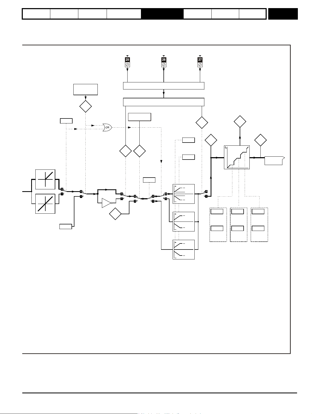
Parameter
Jog
reference
Bipolar
reference
select
Jog selected
indicator
Menu 6
Sequencer
1.10
1.05
1.13
Pre-filter
reference
Pre-ramp
reference
Maximum
speed
"clamp"
Minimum
speed
"clamp"
(Maximum
reverse
speed)
Negative
minimum
speed
select
Reference
enabled
indicator
Reverse
selected
indicator
Skip
speed 1
Reference in skip
speed
band
indicator
Velo city
feed-forward
reference
Feed-forward
selected
indicator
1.12
x(-1)
1.39
1.40
1.08
[1.06]
[1.07]
[1.07]
[1.06]
[1.06]
[1.06]
[1.06]
[1.07]
1.06
1.07
1.11
Sequencer (Menu 6)
1.02
1.03
Menu 2Skip speed
2
Skip
speed 3Skip speed
band 1
Skip speed
band 2
Skip speed
band 3
1.29
1.30
1.31
1.32
1.33
1.34
1.35
Menu 8
JOG
RUN
FORWARD RUN REVERSE
Menu 13
Position control
structure
Keypad and
display
Parameter x.00
Parameter
description format
Advanced parameter
descriptions
Serial comms
protocol
Electronic
nameplate
Performance
Menu 1
Digitax ST Advanced User Guide 23
Issue Number: 3
Page 24
Menu 1
Parameter
structure
Keypad and
display
1.01 Speed reference selected
Coding
Bit SP FI DE Txt VM DP ND RA NC NV PT US RW BU PS
Range ±SPEED_REF_MAX rpm
Update rate 4ms write
1.02 Pre-skip filter reference
Coding
Bit SP FI DE Txt VM DP ND RA NC NV PT US RW BU PS
Range ±SPEED_REF_MAX rpm
Update rate 4ms write
1.03 Pre-ramp reference
Coding
Bit SP FI DE Txt VM DP ND RA NC NV PT US RW BU PS
Range ±SPEED_REF_MAX rpm
Update rate 4ms write
Parameter x.00
Parameter
description format
Advanced parameter
descriptions
11111
11111
11111
Serial comms
protocol
Electronic
nameplate
Performance
1.04 Reference offset
Coding
Bit SP FI DE Txt VM DP ND RA NC NV PT US RW BU PS
111
Range ±40,000.0 rpm
Default 0
Update rate
Background read when precision reference is active
4ms write otherwise
See Pr 1.09 on page 26.
1.05 Jog reference
Coding
Bit SP FI DE Txt VM DP ND RA NC NV PT US RW BU PS
1111
Range 0 to 4,000.0 rpm
Default 0.0
Update rate 4ms read
Reference used for jogging. See section 5.8 Menu 6: Sequencer and clock on page 88 for details on when the jog mode can be activated. The jog
reference can be used for relative jogging in digital lock mode (see section 5.16 Menu 13: Position control on page 166).
1.06
Coding
Maximum reference clamp
Bit SP FI DE Txt VM DP ND RA NC NV PT US RW BU PS
11 111
Range ±SPEED_LIMIT_MAX rpm
Default 3,000.0
Second motor
parameter
Pr 21.01
Update rate Background read
See next page.
24 Digitax ST Advanced User Guide
Issue Number: 3
Page 25
Parameter
structure
Keypad and
display
Parameter x.00
Parameter
description format
Advanced parameter
descriptions
Serial comms
protocol
Electronic
nameplate
Performance
Menu 1
1.07 Minimum reference clamp
Coding
Bit SP FI DE Txt VM DP ND RA NC NV PT US RW BU PS
11 111
Range ±SPEED_LIMIT_MAX rpm*
Default 0.0
Second motor
parameter
Pr 21.02
Update rate Background read
*The range shown for Pr 1.07 shows the range used for scaling purposes (i.e. for routing to an analog output etc.). Further range restrictions are
applied as given below.
Pr 1.08
(Neg min ref enable)
Pr 1.10
(Bipolar mode enable)
Range
0 0 0 to Pr 1.06
01 0
1 0 -SPEED_LIMIT_MAX to 0 rpm
1 1 -SPEED_LIMIT_MAX to 0 rpm
The same limits are applied to Pr 21.02, but based on the value of Pr 21.01.
(If the second motor map is selected Pr 21.01 is used instead of Pr 1.06 and Pr 21.02 instead of Pr 1.07)
1.08 Negative minimum reference clamp enable
Coding
Bit SP FI DE Txt VM DP ND RA NC NV PT US RW BU PS
111
Default 0
Update rate Background read
The effects of the reference clamps (Pr 1.06 and 1.07), the negative minimum clamp enable (Pr 1.08) and the bipolar reference enable parameters
are defined below.
The variable maximum limit for reference parameters, SPEED_REF_MAX, is defined as:
If Pr 1.08 = 0: SPEED_REF_MAX = Pr 1.06
If Pr 1.08=1: SPEED_REF_MAX is Pr 1.06 or -Pr 1.07 whichever is the largest
(If the second motor map is selected Pr 21.01 is used instead of Pr 1.06 and Pr 21.02 instead of Pr 1.07)
Digitax ST Advanced User Guide 25
Issue Number: 3
Page 26
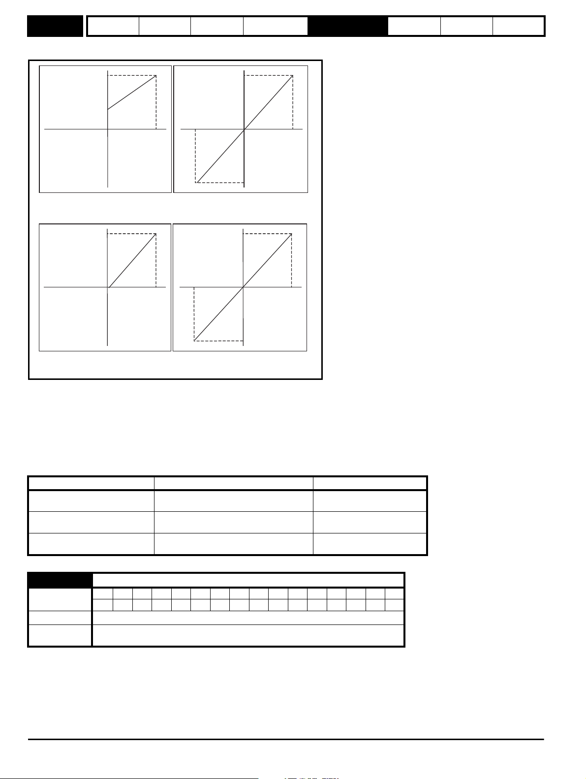
Menu 1
Pr 1.07
Pr =0 (1.10 unipolar mode)
Pr =0 (1.08
neg min ref disabled)
-100% 100%
SPEED_REF_MAX
SPEED_REF_MAX
-100% 100%
-SPEED_REF_MAX
SPEED_REF_MAX
-100% 100%
-SPEED_REF_MAX
Pr =1 (bipolar mode)1.10
Pr =0 (1.08 neg min ref disabled)
-100% 100%
SPEED_REF_MAX
Pr =0 (1.10 unipolar mode)
Pr =1 (1.08 neg min ref enabled)
Pr =1 (bipolar mode)1.10
Pr =1 (1.08 neg min ref enabled)
Parameter
structure
Keypad and
display
Parameter x.00
Parameter
description format
Advanced parameter
descriptions
Serial comms
protocol
Electronic
nameplate
Performance
Analog input scaling
The following diagrams show the scaling applied when analog inputs are used to define the reference and are routed via Pr 1.36 or Pr 1.37.
Reference limits
With reference to the block diagram for Menu 1 (Figure 5-1 on page 22) the following table shows the limits applied to the reference by various blocks
in the reference system. It should be noted that the minimum limit in the main reference limits block changes when either the jog reference or velocity
feedforward references are active.
When one of these is active:
if Pr 1.08 = 0 the minimum = -Pr 1.06 [-Pr 21.01 for motor map 2],
if Pr 1.08 = 1 the minimum = -Pr 1.07 [-Pr 21.02 for motor map 2].
Keypad control reference (Pr 1.17)
Bipolar/unipolar selector
Main reference limits
Unipolar mode: Pr 1.07, or 0 if Pr 1.07 < 0
Bipolar mode: -SPEED_REF_MAX
Unipolar mode: Pr 1.07, or 0 if Pr 1.07 < 0
Bipolar mode: no limit applied
Neg minimum ref disabled: -Pr 1.06
Neg minimum ref enabled: Pr 1.07
Minimum Maximum
SPEED_REF_MAX
No maximum limit applied
Pr 1.06
1.09 Reference offset select
Coding
Default 0
Update rate
Bit SP FI DE Txt VM DP ND RA NC NV PT US RW BU PS
111
Background read when precision reference is active
4ms read otherwise
When this parameter is 0 the reference is given by
Pr 1.01 = selected reference x (100 + Pr 1.38) / 100
and when this parameter is 1 the reference is given by
Pr 1.01 = selected reference + Pr 1.04
26 Digitax ST Advanced User Guide
Issue Number: 3
Page 27
Parameter
structure
Keypad and
display
Parameter x.00
Parameter
description format
Advanced parameter
descriptions
Serial comms
protocol
Electronic
nameplate
Performance
Menu 1
1.10 Bipolar reference enable
Coding
Bit SP FI DE Txt VM DP ND RA NC NV PT US RW BU PS
111
Default 0
Update rate 4ms read
See Pr 1.08 on page 25.
1.11 Reference enabled indicator
1.12 Reverse selected indicator
1.13 Jog selected indicator
Coding
Bit SP FI DE Txt VM DP ND RA NC NV PT US RW BU PS
111
Update rate 4ms read
These parameters are controlled by the drive sequencer as defined in Menu 6. They select the appropriate reference as commanded by the drive
logic. Pr 1.11 will be active if a run command is given, the drive is enabled and the drive is ok. This parameter can be used as an interlock in a
Onboard PLC or SM-Applications program to show that the drive is able to respond to a speed or torque demand.
1.14 Reference selector
Coding
Bit SP FI DE Txt VM DP ND RA NC NV PT US RW BU PS
1111
Range 0 to 5
Default 0 (A1.A2)
Second motor
parameter
Pr 21.03
Update rate 4ms read
Pr 1.14 defines how the value of Pr 1.49 is derived as follows:
Value of Pr 1.14 Display String Pr 1.49
0 A1.A2 (Analog ref 1. Analog ref 2) *Selected by terminal input
1 A1.Pr (Analog ref 1. Preset speeds) 1
2 A2.Pr (Analog ref 2. Preset speeds) 2
3 Pr (Preset speeds) 3
4 Pad (Keypad reference) 4
5 Prc (Precision reference) 5
*Pr 1.41 to Pr 1.44 can be controlled by digital inputs to force the value of Pr 1.49:
all bits equal to zero gives 1,
Pr 1.41 = 1 then Pr 1.49 = 2
Pr 1.42 = 1 then Pr 1.49 = 3
Pr 1.43 = 1 then Pr 1.49 = 4
Pr 1.44 = 1 then Pr 1.49 = 5
The bit parameters with lower numbers have priority over those with higher numbers.
Pr 1.49 and Pr 1.50 then define the reference as follows:
Pr 1.49 Pr 1.50 Reference
1 1 Analog reference 1 (Pr 1.36)
1 >1 Preset defined by Pr 1.50 (Pr 1.21 to Pr 1.28)
2 1 Analog reference 2 (Pr 1.37)
2 >1 Preset defined by Pr 1.50 (Pr 1.21 to Pr 1.28)
3 x** Preset defined by Pr 1.50 (Pr 1.21 to Pr 1.28)
4 x** Keypad reference (Pr 1.17)
5 x** Precision reference (Pr 1.18 and Pr 1.19)
** x = any value
Keypad reference
If Keypad reference is selected the drive sequencer is controlled directly by the keypad keys and the keypad reference parameter (Pr 1.17) is
selected. The sequencing bits, Pr 6.30 to Pr 6.34, have no effect and jog is disabled.
Digitax ST Advanced User Guide 27
Issue Number: 3
Page 28
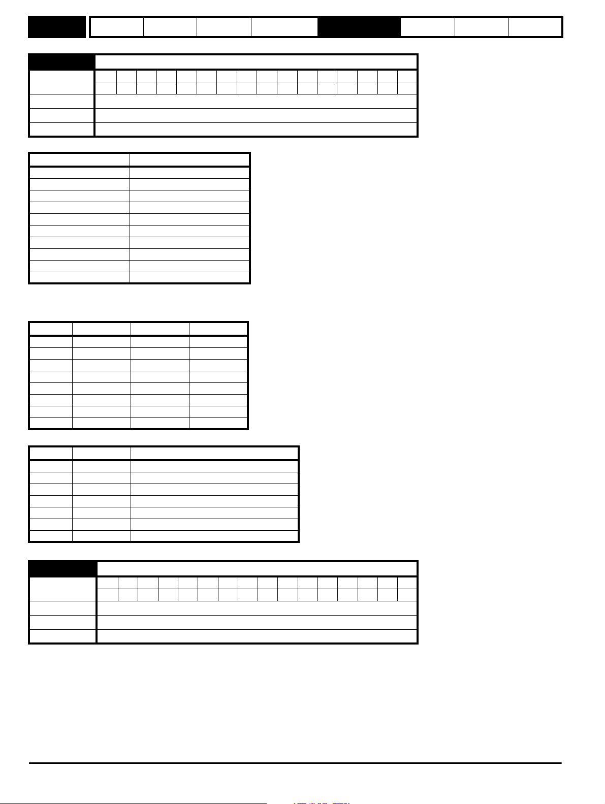
Menu 1
Parameter
structure
Keypad and
display
Parameter x.00
Parameter
description format
Advanced parameter
descriptions
1.15 Preset selector
Coding
Bit SP FI DE Txt VM DP ND RA NC NV PT US RW BU PS
111
Range 0 to 9
Default 0
Update rate 4ms read
Pr 1.15 defines how the value of Pr 1.50 is derived as follows:
Value of Pr 1.15 Pr 1.50
0 Selected by terminal input*
11
22
33
44
55
66
77
88
9 Selected by timer**
*Pr 1.45 to Pr 1.47 can be controlled by digital inputs to define the value of Pr 1.50 as follows:
**The presets are selected automatically in turn. Pr 1.16 defines the time between each change.
Serial comms
protocol
Electronic
nameplate
Performance
Pr 1.47 Pr 1.46 Pr 1.45 Pr 1.50
0001
0012
0103
0114
1005
1016
1107
1118
Pr 1.49 and Pr 1.50 then define the reference as follows:
Pr 1.49 Pr 1.50 Reference
1 1 Analog reference 1 (Pr 1.36)
1 >1 Preset defined by Pr 1.50 (Pr 1.21 to Pr 1.28)
2 1 Analog reference 2 (Pr 1.37)
2 >1 Preset defined by Pr 1.50 (Pr 1.21 to Pr 1.28)
3 x Preset defined by Pr 1.50 (Pr 1.21 to Pr 1.28)
4 x Keypad reference (Pr 1.17)
5 x Precision reference (Pr 1.18 and Pr 1.19)
1.16 Preset reference selector timer
Coding
Bit SP FI DE Txt VM DP ND RA NC NV PT US RW BU PS
1111
Range 0 to 400.0 s
Default 10.0
Update rate Background read
This parameter defines the time between preset reference changes when Pr 1.15 is set to 9. If Pr 1.48 is set to 1 then the preset counter and timer are
reset and preset 1 will be selected.
28 Digitax ST Advanced User Guide
Issue Number: 3
Page 29
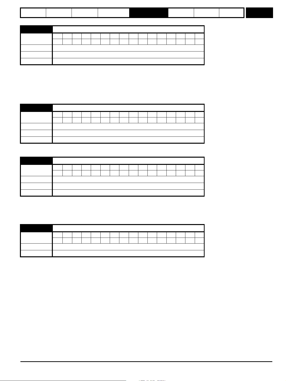
Parameter
structure
Keypad and
display
Parameter x.00
Parameter
description format
Advanced parameter
descriptions
Serial comms
protocol
Electronic
nameplate
Performance
Menu 1
1.17 Keypad control mode reference
Coding
Bit SP FI DE Txt VM DP ND RA NC NV PT US RW BU PS
11 1 1 1
Range ±SPEED_REF_MAX rpm
Default 0.0
Update rate 4ms read
The drive can be controlled from the keypad if Pr 1.14 is set to 4. The Stop and Run keys automatically become active (the Reverse key may be
optionally enabled with Pr 6.13). The speed reference is defined by Pr 1.17. This is a read only parameter that can only be adjusted in status mode by
pressing the Up or Down keys. If keypad control mode is selected, then pressing the Up or Down keys in status mode will cause the drive to
automatically display the keypad reference and adjust it in the relevant direction. This can be done whether the drive is disabled or running. If the Up
or Down keys are held the rate of change of keypad reference increases with time.
See also Pr 1.51 on page 33 (Power-up keypad control mode reference).
1.18 Precision reference coarse
Coding
Bit SP FI DE Txt VM DP ND RA NC NV PT US RW BU PS
11 11
Range ±SPEED_REF_MAX rpm
Default 0.0
Update rate Background read
See below.
1.19 Precision reference fine
Coding
Bit SP FI DE Txt VM DP ND RA NC NV PT US RW BU PS
3111
Range 0.000 to 0.099 rpm
Default 0.000
Update rate Background read
The speed reference resolution is restricted to 0.1rpm from normal parameters, but the resolution can be improved by using the precision reference.
Pr 1.18 defines the coarse part of reference (either positive or negative) with a resolution of 0.1rpm and Pr 1.19 defines the fine part of the reference
(always positive) with a resolution of 0.001rpm. The final reference is given by Pr 1.18 + Pr 1.19. Therefore Pr 1.19 increases positive reference away
from zero, and decreases negative references towards zero.
1.20 Precision reference update disable
Coding
Bit SP FI DE Txt VM DP ND RA NC NV PT US RW BU PS
111
Default 0
Update rate Background read
When this bit is at 0 the precision reference parameters are read and stored in internal memory. Because the precision reference has to be set in two
parameters, this bit is provided to prevent the drive reading the parameters while the reference is being updated. Instead, the drive uses the value
stored in memory preventing the possibility of data skew.
Digitax ST Advanced User Guide 29
Issue Number: 3
Page 30
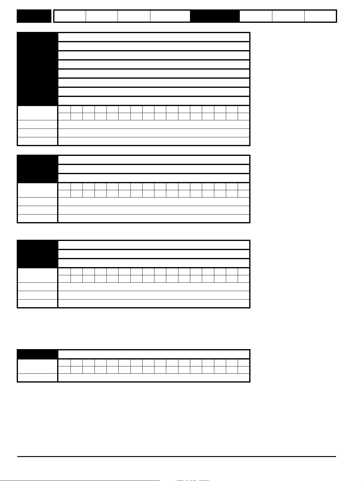
Menu 1
Parameter
structure
Keypad and
display
1.21 Preset reference 1
1.22 Preset reference 2
1.23 Preset reference 3
1.24 Preset reference 4
1.25 Preset reference 5
1.26 Preset reference 6
1.27 Preset reference 7
1.28 Preset reference 8
Coding
Bit SP FI DE Txt VM DP ND RA NC NV PT US RW BU PS
Range ±SPEED_REF_MAX rpm
Default 0.0
Update rate 4ms read
1.29 Skip reference 1
1.31 Skip reference 2
1.33 Skip reference 3
Coding
Bit SP FI DE Txt VM DP ND RA NC NV PT US RW BU PS
Range 0 to 40,000 rpm
Default 0
Update rate Background read
See below.
Parameter x.00
Parameter
description format
Advanced parameter
descriptions
11 11
111
Serial comms
protocol
Electronic
nameplate
Performance
1.30 Skip reference band 1
1.32 Skip reference band 2
1.34 Skip reference band 3
Coding
Bit SP FI DE Txt VM DP ND RA NC NV PT US RW BU PS
111
Range 0 to 250 rpm
Default 5
Update rate Background read
Three skip references are available to prevent continuous operation at a speed that would cause mechanical resonance. When a skip reference
parameter is set to 0 that filter is disabled. The skip reference band parameters define the speed range either side of the programmed skip reference,
over which references are rejected. The actual reject band is therefore twice that programmed in these parameters, the skip reference parameters
defining the centre of the band. When the selected reference is within a band the lower limit of the band is passed through to the ramps such that
reference is always less than demanded.
1.35 Reference in rejection zone
Coding
Bit SP FI DE Txt VM DP ND RA NC NV PT US RW BU PS
1 111
Update rate 4ms write
This parameter indicates that the selected reference is within one of the skip reference zones such that the motor speed is not as demanded.
30 Digitax ST Advanced User Guide
Issue Number: 3
Page 31

Parameter
structure
Keypad and
display
Parameter x.00
Parameter
description format
Advanced parameter
descriptions
Serial comms
protocol
Electronic
nameplate
Performance
Menu 1
1.36 Analog reference 1
1.37 Analog reference 2
Coding
Bit SP FI DE Txt VM DP ND RA NC NV PT US RW BU PS
111 1
Range ±SPEED_REF_MAX rpm
Default 0
Update rate 4ms write
Although most parameters can be controlled from analog inputs, these two parameters are a special case in that if an analog input is directed to one
of these parameters, the scan rate of that analog input is increased to 250μs as long as:
1. The reference must be derived via Pr 1.36 or Pr 1.37
2. The analog inputs must be in voltage mode with zero offset
3. Bipolar mode must be used or unipolar mode with the minimum speed (Pr 1.07) set to zero
4. No skip bands are enabled, i.e. Pr 1.29, Pr 1.31 and Pr 1.33 must be zero.
5. The jog and velocity feed-forward references must not be enabled.
These are special parameters when a non-bit type quantity uses these parameters as a destination (not just from analog inputs). The scaling and
limiting applied is as described with Pr 1.08 on page 25.
1.38 Percentage trim
Coding
Bit SP FI DE Txt VM DP ND RA NC NV PT US RW BU PS
21 1
Range ±100.00 %
Default 0.00
Update rate 4ms read
See Pr 1.09 on page 26.
1.39 Velocity feed forward
Coding
Bit SP FI DE Txt VM DP ND RA NC NV PT US RW BU PS
1111
Range ±40,000.0 rpm
Update rate 4ms read
This parameter indicates the velocity feed forward reference when position control is used (see section 5.16 Menu 13: Position control on page 166).
1.40 Velocity feed forward select
Coding
Bit SP FI DE Txt VM DP ND RA NC NV PT US RW BU PS
1 111
Update rate 4ms write
This bit indicates that the position controller has selected the velocity feed forward as a reference for the drive.
Digitax ST Advanced User Guide 31
Issue Number: 3
Page 32

Menu 1
Parameter
structure
Keypad and
display
Parameter x.00
Parameter
description format
Advanced parameter
descriptions
Serial comms
protocol
Electronic
nameplate
Performance
1.41 Analog reference 2 select
1.42 Preset reference select
1.43 Keypad reference select
1.44 Precision reference select
1.45 Preset reference 1 select
1.46 Preset reference 2 select
1.47 Preset reference 3 select
Coding
Bit SP FI DE Txt VM DP ND RA NC NV PT US RW BU PS
111
Default 0
Update rate 4ms read
Pr 1.41 to Pr 1.44 control Pr 1.49. The priority order is Pr 1.44 (highest), Pr 1.43, Pr 1.42, Pr 1.41 (lowest). If more than one parameter is active, the
highest priority takes precedence.
Pr 1.41 = 1 forces Pr 1.49 = 2 (see table in Pr 1.14 on page 27 and Pr 1.15 on page 28)
Pr 1.42 = 1 forces Pr 1.49 = 3 (always selects preset references)
Pr 1.43 = 1 forces Pr 1.49 = 4 (always selects keypad control mode)
Pr 1.44 = 1 forces Pr 1.49 = 5 (always selects precision reference)
Pr 1.45 to Pr 1.47 control Pr 1.50.
Pr 1.45 controls Pr 1.50 bit 0*
Pr 1.46 controls Pr 1.50 bit 1*
Pr 1.47 controls Pr 1.50 bit 2*
*See the description with Pr 1.14 and Pr 1.15 on page 28 for more information.
1.48 Reference timer reset flag
Coding
Bit SP FI DE Txt VM DP ND RA NC NV PT US RW BU PS
111
Default 0
Update rate Background read
When this flag is set the preset timer for auto preset timer mode (Pr 01.15 = 9) is reset and preset 1 is selected. This can be used to start a new
sequence of reference selection by a programmable input terminal or function. When this bit is zero the preset selection will follow the timer even
when the drive is disabled.
1.49 Reference selected indicator
Coding
Bit SP FI DE Txt VM DP ND RA NC NV PT US RW BU PS
111 1
Range 1 to 5
Update rate 4ms write
Indicates the reference currently selected.
1.50 Preset reference selected indicator
Coding
Bit SP FI DE Txt VM DP ND RA NC NV PT US RW BU PS
111 1
Range 1 to 8
Update rate 4ms write
Indicates the preset reference currently being selected.
32 Digitax ST Advanced User Guide
Issue Number: 3
Page 33

Parameter
structure
Keypad and
display
Parameter x.00
Parameter
description format
Advanced parameter
descriptions
1.51 Power-up keypad control mode reference
Coding
Bit SP FI DE Txt VM DP ND RA NC NV PT US RW BU PS
1111
Range 0 to 2
Default 0
Update rate N/A
Selects the value of the keypad control mode (Pr 1.17) at power-up as follows:
0 rESEt zero
1 LASt last value used before power-down
2 PrS1 Preset 1, Pr 1.21, before power-down
Serial comms
protocol
Electronic
nameplate
Performance
Menu 1
Digitax ST Advanced User Guide 33
Issue Number: 3
Page 34

Menu 2
0 0 0
0 0 1
0 1 0
0 1 1
1 0 0
1 0 1
1 1 0
1 1 1
Acceleration rate select bits
2.11
Acceleration rate 1
2.12
Acceleration rate 2
2.13
Acceleration rate 3
2.14
Acceleration rate 4
2.15
Acceleration rate 5
2.16
Acceleration rate 6
2.17
Acceleration rate 7
2.18
Acceleration rate 8
Acceleration rates 1 ~ 8
1.50
3
4
1
2
7
5
6
Preset reference
selected indicator
2.19
Jog acceleration
rate
1.13
Jog selected
indicator
1.03
Pre-ramp speed
reference
2.03
Ramp hold
2.04
Ramp mode
select*
NtN
t
Acceleration
Reverse
accel. rate
Forward
accel. rate
Ramp control
2.10
Acceleration
rate selector
2.34
2.32
2.33
2.32
0.XX
0.XX
Key
Read-write (RW)
parameter
Read-only (RO)
parameter
Input
terminals
Output
terminals
The parameters are all shown at their default settings
8
Figure 5-2 Menu 2 logic diagram
Parameter
structure
Keypad and
display
Parameter x.00
Parameter
description format
Advanced parameter
descriptions
Serial comms
protocol
Electronic
nameplate
5.4 Menu 2: Ramps
The pre-ramp speed reference passes through the ramp block controlled by menu 2 before being used by the drive as an input to the speed
controller. The ramp block includes: linear ramps, an S ramp function for ramped acceleration and deceleration, deceleration ramp control to prevent
rises in the DC bus voltage within the drive that would cause an over-voltage trip if no braking resistor is installed.
Performance
34 Digitax ST Advanced User Guide
Issue Number: 3
Page 35

Parameter
2.06
S-Ramp enable**
2.07
S-Ramp acceleration
limit
2.08
Standard ramp voltage*
Ramp control
N
t
N
t
Deceleration
Forward
Decel. rate
Reverse
Decel. rate
2.01
Post-ramp
reference
2.02
Ramp
enable
Deceleration rate select bits
2.21
Deceleration rate 1
2.22
Deceleration rate 2
2.23
Deceleration rate 3
2.24
Deceleration rate 4
2.25
Deceleration rate 5
2.26
Deceleration rate 6
2.27
Deceleration rate 7
2.28
Deceleration rate 8
Deceleration rates 1 ~ 8
341278562.37
1.50
Preset reference
selected indicator
2.29
Jog deceleration
rate
1.13
Jog selected
indicator
2.38
Inertia compensation
torque
d/dt
2.20
Deceleration
rate selector
2.36
2.35
structure
Keypad and
display
Parameter x.00
description format
* For more information refer to Pr 2.04 on page 36.
** For more information refer to Pr 2.06 on page 37.
Parameter
Advanced parameter
descriptions
Serial comms
protocol
Electronic
nameplate
Performance
Menu 2
Digitax ST Advanced User Guide 35
Issue Number: 3
Page 36

Menu 2
DC Bus voltage
Motor Speed
Programmed
deceleration
rate
t
Controller
operational
Parameter
structure
Keypad and
display
Parameter x.00
Parameter
description format
Advanced parameter
descriptions
Serial comms
protocol
Electronic
nameplate
Performance
2.01 Post ramp reference
Coding
Bit SP FI DE Txt VM DP ND RA NC NV PT US RW BU PS
11111
Range ±SPEED_REF_MAX rpm
Update rate 4ms write
2.02 Ramp enable
Coding
Bit SP FI DE Txt VM DP ND RA NC NV PT US RW BU PS
1111
Default 1
Update rate 4ms read
2.03 Ramp hold
Coding
Bit SP FI DE Txt VM DP ND RA NC NV PT US RW BU PS
111
Default 0
Update rate 4ms read
If this bit is set the ramp will be held. If S ramp is enabled the acceleration will ramp towards zero causing the ramp output to curve towards a constant
speed. If a drive stop is demanded the ramp hold function is disabled.
2.04 Ramp mode select
Coding
Bit SP FI DE Txt VM DP ND RA NC NV PT US RW BU PS
1111
Range 0 to 1
Default 1
Update rate 4ms read
This parameter does not affect the acceleration ramp, and the ramp output always rises at the programmed acceleration rate subject to the current
limits. If the drive attempts to stop the motor with an overhauling load, the motor will not stop when standard ramp mode or fast ramp mode is used. If
the drive is in the deceleration state the rate of fall of the speed is monitored. If this does not fall for 10 seconds the drive forces the speed reference
to zero. This only applies when the drive is in the deceleration state and not when the reference is simply set to zero. If the speed reference is just set
to zero with an overhauling or very high inertia load, then the drive may not decelerate.
0: Fast ramp
Fast ramp is used where the deceleration follows the programmed deceleration rate subject to current limits.
1: Standard ramp
Standard ramp is used during deceleration if the voltage rises to the standard ramp level (Pr 2.08). It causes a controller to operate, the output of
which changes the demanded load current in the motor. As the controller regulates the DC bus voltage, the motor deceleration increases as the
speed approaches zero speed. When the motor deceleration rate reaches the programmed deceleration rate the controller ceases to operate and the
drive continues to decelerate at the programmed rate. If the standard ramp voltage (Pr 2.08) is set lower than the nominal DC bus level the drive will
not decelerate the motor, but it will coast to rest. The output of the ramp controller (when active) is a current demand that is fed to the torque
producing current controller. The gain of these controllers can be modified with Pr 4.13 and Pr 4.14.
36 Digitax ST Advanced User Guide
Issue Number: 3
Page 37

Parameter
t
Acceleration
Actual Speed
Programmed
ramp rate
TT
T/2 T/2 T/2T/2
S ramp
acceleration
ramp
Demanded Speed
structure
Keypad and
display
Parameter x.00
Parameter
description format
Advanced parameter
descriptions
Serial comms
protocol
Electronic
nameplate
Performance
Menu 2
2.06 S ramp enable
Coding
Bit SP FI DE Txt VM DP ND RA NC NV PT US RW BU PS
111
Default 0
Update rate 4ms read
Setting this parameter enables the S ramp function. S ramp is disabled during deceleration when the standard ramp voltage controller is active. When
the motor is accelerated again after decelerating in standard ramp the acceleration ramp used by the S ramp function is reset to zero.
2.07 S ramp acceleration limit
Coding
Range
Bit SP FI DE Txt VM DP ND RA NC NV PT US RW BU PS
3111
2
0.000 to 100.000 s
/1,000rpm
Default 0.030
Update rate Background read
This parameter defines the maximum rate of change of acceleration/deceleration. If the S ramp is disabled (Pr 2.06 = 0) a linear ramp is used and the
time in seconds taken for the ramp output to change by speed (Δ w*) is given by:
T
Δw* x A / 1000
Ramp =
Where A is the selected ramp rate in s / 1000rpm
If the S ramp is enabled (Pr 2.06 = 1) then the ramp time is extended as shown in the diagram below.
The time taken in seconds for the ramp output to change by speed (Δw*) is given below. Two cases are given because the total ramp time must be
calculated with a different equation depending on whether the acceleration is able to reach the selected ramp rate (A) or not. If the required change is
small the selected ramp rate is not reached and the ramp does not include the central linear ramp region. If the required change is larger the ramp
does include the central linear region as shown in the diagram above.
Δw*
= 1000 x J / A
linear
2
where:
A is the selected ramp rate in s / 1000rpm
2
linear
/ 1000rpm
then T
should be used, but if the speed change is greater or equal to Δw*
Ramp1
linear
T
Ramp2
should be
J is Pr 2.07, the S ramp acceleration limit in s
If the required change is less than Δw*
used.
T
= 2 √ (Δw* x J / 1000)
Ramp1
= (Δw* x A / 1000) + (J / A)
T
Ramp2
The default values for the ramp rate and S ramp acceleration limit have been chosen such that for the default maximum speed, the curved parts of the
S ramp are 25% of the original ramp if S ramp is enabled. Therefore the ramp time is increased by a factor of 1.5.
Digitax ST Advanced User Guide 37
Issue Number: 3
Page 38

Menu 2
Parameter
structure
Keypad and
display
Parameter x.00
Parameter
description format
Advanced parameter
descriptions
Serial comms
protocol
Electronic
nameplate
Performance
2.08 Standard ramp voltage
Coding
Bit SP FI DE Txt VM DP ND RA NC NV PT US RW BU PS
11 111
Range 0 to DC_VOLTAGE_SET_MAX V
Default
200V rating drive: 375
400V rating drive: EUR: 750 / USA: 775
Update rate Background read
This voltage is used as the control level for standard ramp mode. If this parameter is set too low the machine will coast to rest, and if it is set too high
and no braking resistor is used the drive may give an OU trip. The minimum level should be greater than the voltage produced on the DC bus by the
highest supply voltage. Normally the DC bus voltage will be approximately the rms supply line voltage x √2.
2.10 Acceleration rate selector
Coding
Bit SP FI DE Txt VM DP ND RA NC NV PT US RW BU PS
111
Range 0 to 9
Default 0
Update rate 4ms read
The acceleration rate is selected as follows.
0 Ramp rate selection by terminal input
1 - 8 Ramp rate defined by parameter number, i.e. 1 = Pr 2.11, 2 = Pr 2.12, etc.
9 Ramp rate selection by Pr 1.50
When Pr 2.10 is set to 0 the acceleration ramp rate selected depends on the state of bit Pr 2.32 to Pr 2.34. These bits are for control by digital inputs
such that ramp rates can be selected by external control. The ramp rate selected depends on the binary code generated by these bits as follows:
Pr 2.34 Pr 2.33 Pr 2.32 Ramp defined by
00 0 Pr 2.11
00 1 Pr 2.12
01 0 Pr 2.13
01 1 Pr 2.14
10 0 Pr 2.15
10 1 Pr 2.16
11 0 Pr 2.17
11 1 Pr 2.18
When Pr 2.10 is set to 9 the appropriate acceleration rate is automatically selected depending on the value of Pr 1.50, and so an acceleration rate can
be programmed to operate with each reference. Since the new ramp rate is selected with the new reference, the acceleration applies towards the
selected preset if the motor needs to accelerate to reach the preset.
2.11 Acceleration rate 1
2.12 Acceleration rate 2
2.13 Acceleration rate 3
2.14 Acceleration rate 4
2.15 Acceleration rate 5
2.16 Acceleration rate 6
2.17 Acceleration rate 7
2.18 Acceleration rate 8
Coding
Bit SP FI DE Txt VM DP ND RA NC NV PT US RW BU PS
3111
Range 0.000 to 3,200.000 s/1000rpm
Default 0.200
Second motor
parameter
Pr 21.04 for Pr 2.11 only
Update rate 4ms read
If an acceleration rate is selected where the parameter is set to 0.000 the acceleration ramp is disabled and the reference changes instantly to its new
value during acceleration.
38 Digitax ST Advanced User Guide
Issue Number: 3
Page 39

Parameter
structure
Keypad and
display
Parameter x.00
Parameter
description format
Advanced parameter
descriptions
Serial comms
protocol
Electronic
nameplate
Performance
Menu 2
2.19 Jog acceleration rate
Coding
Bit SP FI DE Txt VM DP ND RA NC NV PT US RW BU PS
1111
Range 0.000 to 3200.000 s/1000rpm
Default 0.000
Update rate Background read
The jog acceleration rate is only used when accelerating towards the jog reference and when changing the jog reference.
2.20 Deceleration rate selector
Coding
Bit SP FI DE Txt VM DP ND RA NC NV PT US RW BU PS
111
Range 0 to 9
Default 0
Update rate 4ms read
The acceleration rate is selected as follows:
0 Ramp rate selection by terminal input
1 - 8 Ramp rate defined by parameter number, i.e. 1 = Pr 2.21, 2 = Pr 2.22, etc.
9 Ramp rate selection by Pr 1.50
When Pr 2.20 is set to 0 the deceleration ramp rate selected depends on the state of bit Pr 2.35 to Pr 2.37. These bits are for control by digital inputs
such that ramp rates can be selected by external control. The ramp rate selected depends on the binary code generated by these bits as follows:
02.37 02.36 02.35 Ramp defined by
00 0 Pr 2.21
00 1 Pr 2.22
01 0 Pr 2.23
01 1 Pr 2.24
10 0 Pr 2.25
10 1 Pr 2.26
11 0 Pr 2.27
11 1 Pr 2.28
When Pr 2.20 is set to 9 the appropriate deceleration rate is automatically selected depending on the value of Pr 1.50, and so a deceleration rate can
be programmed to operate with each reference. Since the new ramp rate is selected with the new reference, the deceleration applies towards the
selected preset if the motor needs to decelerate to reach the preset.
2.21 Deceleration rate 1
2.22 Deceleration rate 2
2.23 Deceleration rate 3
2.24 Deceleration rate 4
2.25 Deceleration rate 5
2.26 Deceleration rate 6
2.27 Deceleration rate 7
2.28 Deceleration rate 8
Coding
Bit SP FI DE Txt VM DP ND RA NC NV PT US RW BU PS
3111
Range 0.000 to 3,200.000 s/1000rpm
Default 0.200
Second motor
parameter
Pr 21.05 for Pr 2.21 only
Update rate 4ms read
If an deceleration rate is selected where the parameter is set to 0.000 the deceleration ramp is disabled and the reference changes instantly to its new
value during deceleration.
Digitax ST Advanced User Guide 39
Issue Number: 3
Page 40

Menu 2
Parameter
structure
Keypad and
display
Parameter x.00
Parameter
description format
Advanced parameter
descriptions
Serial comms
protocol
Electronic
nameplate
Performance
2.29 Jog deceleration rate
Coding
Range
Default
Bit SP FI DE Txt VM DP ND RA NC NV PT US RW BU PS
3111
0.000 to 3,200.000 s/1000rpm
0.000
Update rate Background read
The jog deceleration rate is only used when the drive is changing speed because the jog reference has changed or to stop from the jog reference. It
is not used to go from the jog to the run state. This prevents the fast ramps normally used with jog from being used when changing between running
and jogging.
2.32 Acceleration select bit 0
2.33 Acceleration select bit 1
2.34 Acceleration select bit 2
2.35 Deceleration select bit 0
2.36 Deceleration select bit 1
2.37 Deceleration select bit 2
Coding
Bit SP FI DE Txt VM DP ND RA NC NV PT US RW BU PS
111
Update rate 4ms read
These bits are provided for control by logic input terminals for external ramp selection (see Pr 2.10 and Pr 2.20).
2.38 Inertia compensation torque
Coding
Bit SP FI DE Txt VM DP ND RA NC NV PT US RW BU PS
1111
Range ±1,000.0 %
Update rate 4ms write
The motor and load inertia (Pr 3.18), motor torque per amp (Pr 5.32) and the rate of change of the ramp output (Pr 2.01) are used to produce a torque
feed forward value that should accelerate or decelerate the load at the required rate. This value can be used as a feed forward term that is added to
the speed controller output if Pr 4.22 is set to one. Pr 2.38 shows the torque value as a percentage of rated active current.
40 Digitax ST Advanced User Guide
Issue Number: 3
Page 41

Parameter
structure
Keypad and
display
Parameter x.00
Parameter
description format
Advanced parameter
descriptions
Serial comms
protocol
Electronic
nameplate
Performance
Menu 3
5.5 Menu 3: Speed feedback and speed control
Menu 3 relates to different functions which are:-
• Speed feedback
• Speed controller
• “Zero speed”, “at speed” and overspeed detectors
• Drive encoder.
Speed accuracy and resolution
Digital reference resolution
When a preset speed is used the reference resolution is 0.1rpm. Improved resolution can be obtained by using the precision reference (0.001rpm).
Analog reference resolution
The resolution from analog input 1 is better than 16bits plus sign provided the speed reference is routed via Pr 1.36, Pr 1.37 or Pr 3.22 in high speed
update mode. The resolution from analog inputs 2 or 3 is 10bits plus sign.
Accuracy
The absolute speed accuracy depends on the accuracy of the crystal used with the drive microprocessor. The accuracy of the crystal is 100ppm, and
so the absolute speed accuracy is 100ppm (0.01%) of the reference, when a preset speed is used. If an analog input is used the absolute accuracy is
further limited by the absolute accuracy and non-linearity of the analog input.
Digitax ST Advanced User Guide 41
Issue Number: 3
Page 42

Menu 3
15 way sub-D
connector
Encoder
1
2
3
4
5
6
A
A
B
B
Z
Z
U
U
V
V
W
W
7
8
9
10
11
12
3.38
Drive encoder
type
3.34
Drive encoder lines
per revolution
3.39
Drive encoder
termination disable
3.36
Drive encoder
supply voltage**
3.25
Encoder phase
angle*
ENCODER INTERFACE
DRIVE ENCODER POSITION
3.28
Drive encoder
revolution counter
3.29
Drive encoder
position
3.30
Drive encoder
fine position
2.01
Post-ramp
reference
+
+
0
1
0
1
3.23
1.11
Hard speed
reference
selector
Reference
enabled
indicator
3.01
Final speed
reference
3.22
Hard speed
reference
3.50
Position feedback
lock
15.03
Speed feedback
from option
module in slot 1
16.03
Speed feedback
from option
module in slot 2
Feedback from the
option modules set-up
in Menus 15 and 16
3.27
Drive encoder
speed feedback
0
1
2
3.26
Speed feedback
selector
3.45
3.44
Any unprotected
variable parameter
??.??
??.??
3.46
Drive
encoder
reference
Drive encoder
reference scaling
Drive encoder
reference
destination
3.43
Maximum drive
encoder
reference (rpm)
3.42
Drive encoder
filter
1
Buffered
encoder
output mode
3.52
Ratio
numerator
1
2
Fd
Fr
Ab.L
3
0
Ab
4
Fb.L
SK4
Term
1
2
3
4
5
6
7
8
9
10
11
12
13
14
15
Ab (0)
A
A\
B
B\
Z
Z\
Fd (1)
F
F\
D
D\
Z
Z\
Fr (2)
F
F\
R
R\
Z
Z\
Ab.L (3)
A
A\
B
B\
Z
Z\
Fd.L (4)
F
F\
D
D\
Z
Z\
0V common
Buffered encoder out
15 way sub-D
connector
SK4
3.54
Parameter
structure
Keypad and
Figure 5-3 Menu 3 Logic diagram
display
Parameter x.00
Parameter
description format
Advanced parameter
descriptions
Serial comms
protocol
Electronic
nameplate
Performance
42 Digitax ST Advanced User Guide
Issue Number: 3
Page 43

Parameter
+
_
3.03
Speed
error
+
_
Speed loop gains
3.04
Speed
controller
output
Menu 4
+
_
Overspeed trip
(O.SPd)
1.06
Max reference clamp
+
_
3.06
10.05
Below at-speed
window indicator
At speed
lower limit
+
_
3.07
10.07
Above at-speed
window indicator
At speed
upper limit
10.06
At speed
indicator
NOR
+
_
3.05
10.03
At zero speed
indicator
Zero speed
threshold
+
_
1.07
10.04
At or below min.
speed indicator
Minimum
speed
0
1
1.10
Bipolar reference
select
+5min
-1
+20%
1.03
Pre ramp
reference
3.09
Absolute at-speed
detect mode
0
1
Speed controller
differential
feedback gains
0.XX
0.XX
Key
Read-write (RW)
parameter
Read-only (RO)
parameter
Input
terminals
Output
terminals
X
X
X
X
The parameters are all shown at their default settings
0
1
3.08
Overspeed threshold
3.08 >0
Speed controller
gain select
3.10
3.11
(Ki1)
(Kp1)
3.13
3.14
(Ki2)
(Kp2)
3.16
Speed feedback
3.02
+
_
(Kd1)
(Kd2)
3.153.12
0
1
10
structure
Keypad and
display
Parameter x.00
Parameter
description format
Advanced parameter
descriptions
Serial comms
protocol
Electronic
nameplate
Performance
Menu 3
Digitax ST Advanced User Guide 43
Issue Number: 3
Page 44

Menu 3
Speed controller
Drive encoder
reference system
Filter defined
by Pr
3.42
16ms filter
Pr and Pr
3.02 3.27
From the drive
encoder port
Parameter
structure
Keypad and
display
Parameter x.00
Parameter
description format
Advanced parameter
descriptions
Serial comms
protocol
Electronic
nameplate
Performance
3.01 Final speed reference
Coding
Bit SP FI DE Txt VM DP ND RA NC NV PT US RW BU PS
1 11111
Range ±SPEED_MAX rpm
Update rate 4ms write
This is the final speed demand at the input to the speed regulator formed by the sum of the ramp output and the hard speed reference (if the hard
speed reference is enabled). If the drive is disabled this parameter will show 0.0.
3.02 Speed Feedback
Coding
Bit SP FI DE Txt VM DP ND RA NC NV PT US RW BU PS
1 11111
Range ±SPEED_MAX rpm
Update rate 4ms write
The speed feedback can be taken from the drive encoder port or a position feedback module installed in any slot as selected with Pr 3.26. Pr 3.02
shows the level of the speed feedback selected for the speed controller. The FI attribute is set for this parameter, so display filtering is active when this
parameter is viewed with one of the drive keypads. The value held in the drive parameter (accessible via comms or a Solutions Module) does not
include this filter, but is a value that is obtained over a sliding 16ms period to limit the ripple seen in this parameter value. The speed feedback value
includes encoder quantization ripple given by the following equation:
Ripple in Pr 3.02 = 60 / 16ms / (ELPR x 4)
where ELPR is the equivalent encoder lines per revolution as defined below.
Position feedback device ELPR
Ab, Ab.Servo number of lines per revolution
Fd, Fr, Fd.Servo, Fr.Servo number of lines per revolution / 2
SC.Hiper, SC.EnDat, SC, SC.SSI number of sine waves per revolution
For example a 4096 line Ab type encoder gives a ripple level of 0.23rpm.
The 16ms sliding window filter is always applied to the value shown in Pr 3.02, but this sliding window filter is not normally applied to the actual speed
feedback used by the speed controller or the drive encoder reference system (Pr 3.43 to Pr 3.46).The user may apply a filter to the speed controller
input and the drive encoder reference system input if required by setting Pr 3.42 to the required filter time. The encoder ripple seen by the speed
controller is given by:
Encoder speed ripple = 60 / Filter time / (ELPR x 4)
If Pr 3.42 is set to zero (no filter) the ripple seen by the speed controller and drive encoder reference system is given by:
Encoder speed ripple = 60 / 250μs / (ELPR x 4)
The diagram above shows the filter arrangement. It should be noted that the same filtering is provided at the speed controller input and for Pr 3.02
when the feedback is obtained from a Solutions Module, but the variable length window filter is controlled by Pr x.19.
It is not advisable to use the speed feedback filter unless it is specifically required for high inertia applications with high controller gains, or if a
commutation signal only encoder is used, because the filter has a non-linear transfer function. It is preferable to use the current demand filters (see Pr
4.12 or 4.23) as these are linear first order filters that provide filtering on noise generated from both the speed reference and the speed feedback. It
should be noted that any filtering included within the speed controller feedback loop, either on the speed feedback or the current demand, introduces
a delay and limits the maximum bandwidth of the controller for stable operation.
The speed ripple can be quite high, for example with a 4096 line encoder the speed ripple is 14.6rpm, but this does not define the resolution of the
speed feedback which is normally much better and depends on the length of the measuring period used to obtain the feedback. This is shown in the
improved resolution of the value accessible in Pr 3.02 which is measured over 16ms, i.e. a resolution of 0.23rpm with a 4096 line encoder. The speed
controller itself accumulates all pulses from the encoder, and so the speed controller resolution is not limited by the feedbac
the speed reference. If a SINCOS encoder is used the encoder speed ripple is reduced by a factor of 2
( 2 - INTERPOLATION BITS)
k, but by the resolution of
For example with the
nominal 10 bits of interpolation information, the speed ripple is reduced by a factor of 256. This shows how a SINCOS encoder can reduce noise
caused by encoder quantization without any filtering in the speed feedback or the current demand, so that high gains may be used to give high
dynamic performance and a very stiff system.
44 Digitax ST Advanced User Guide
Issue Number: 3
Page 45
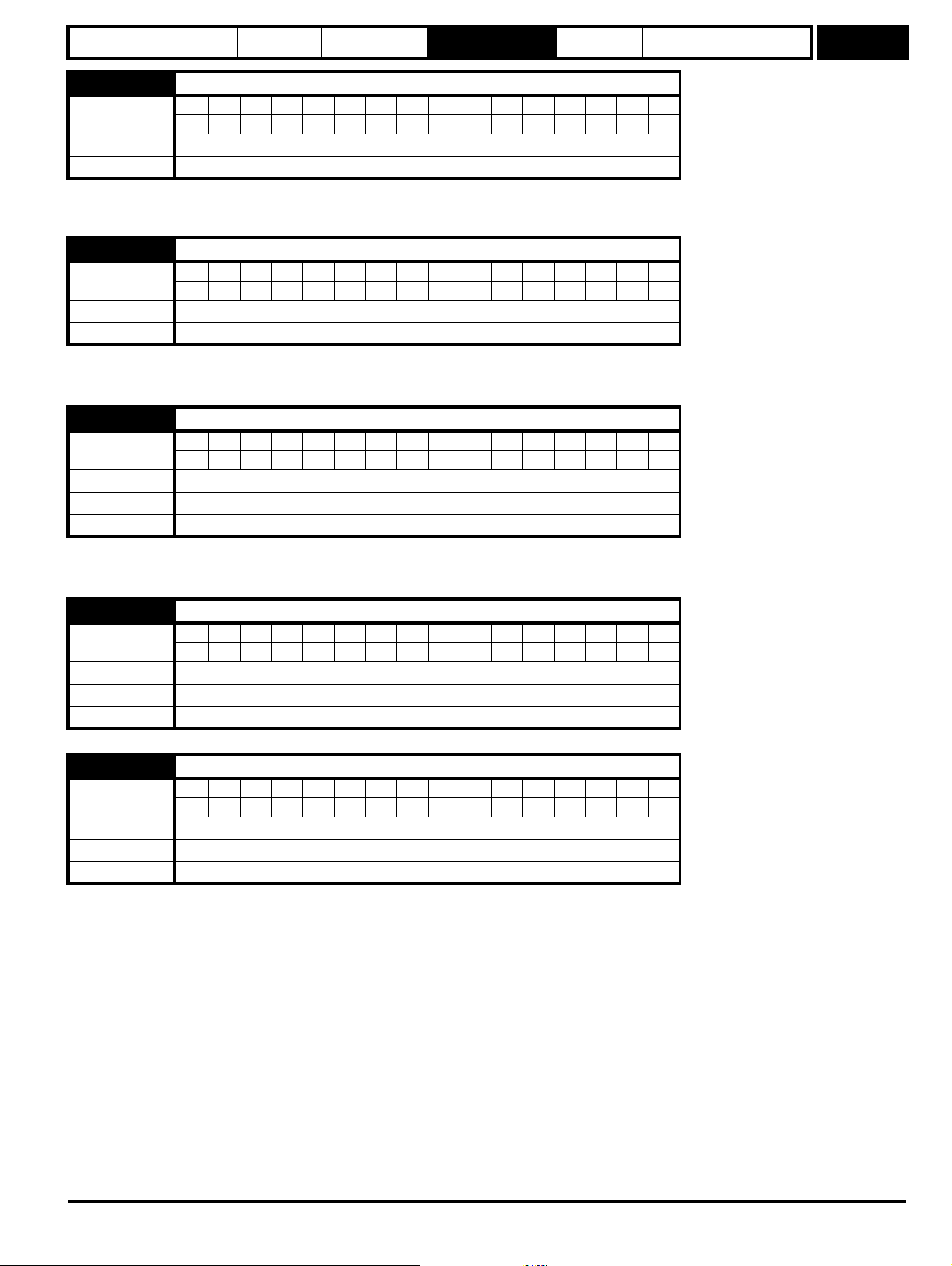
Parameter
structure
Keypad and
display
Parameter x.00
Parameter
description format
Advanced parameter
descriptions
Serial comms
protocol
Electronic
nameplate
Performance
Menu 3
3.03 Speed error
Coding
Bit SP FI DE Txt VM DP ND RA NC NV PT US RW BU PS
1 11111
Range ±SPEED_MAX rpm
Update rate 4ms write
The speed error is the difference between the final speed demand and the speed feedback in rpm. This does not include the effect of the D term in the
speed controller feedback branch.
3.04 Speed controller output
Coding
Bit SP FI DE Txt VM DP ND RA NC NV PT US RW BU PS
1 11111
Range ±TORQUE_PROD_CURRENT_MAX %
Update rate 4ms write
The output of the speed regulator is a torque demand given as a percentage of rated motor torque. This is then modified to account for changes in
motor flux if field weakening is active, and then used as the torque producing current reference.
3.05 Zero speed threshold
Coding
Bit SP FI DE Txt VM DP ND RA NC NV PT US RW BU PS
111
Range 0 to 200 rpm
Default 5
Update rate Background read
If the speed feedback (Pr 3.02) is at or below the level defined by this parameter in either direction the Zero speed flag (Pr 10.03) is 1, otherwise the
flag is 0.
3.06 At speed lower limit
Coding
Bit SP FI DE Txt VM DP ND RA NC NV PT US RW BU PS
111
Range 0 to 40,000 rpm
Default 5
Update rate Background read
3.07 At speed upper limit
Coding
Bit SP FI DE Txt VM DP ND RA NC NV PT US RW BU PS
111
Range 0 to 40,000 rpm
Default 5
Update rate Background read
"At speed" flag (Pr 10.06) is set if the speed feedback (Pr 3.02) is on the boundaries or within the at speed window. Flags Pr 10.07 and Pr 10.05 are
set if the reference is above or below the window respectively.
If Pr 3.09 = 0 reference window mode is used and the "at speed" condition is true if
(|Pr 1.03| - Pr 3.06) ≤ |Pr 3.02| ≤ (|Pr 1.03| + Pr 3.07)
(If the lower limit is less than zero then zero is used as the lower limit.)
If Pr 3.09 = 1 absolute window mode is used and the "at speed" condition is true if
Pr 3.06 ≤ |Pr 3.02| ≤ Pr 3.07
Digitax ST Advanced User Guide 45
Issue Number: 3
Page 46

Menu 3
Parameter
structure
Keypad and
display
Parameter x.00
Parameter
description format
Advanced parameter
descriptions
Serial comms
protocol
Electronic
nameplate
Performance
3.08 Overspeed threshold
Coding
Bit SP FI DE Txt VM DP ND RA NC NV PT US RW BU PS
111
Range 0 to 40,0000 rpm
Default 0
Update rate Background read
If the speed feedback (Pr 3.02) exceeds this level in either direction an overspeed trip is produced. If this parameter is set to zero the overspeed
threshold is automatically set to 1.2 x SPEED_REF_MAX.
The motor speed and the motor voltage can be monitored to detect that the motor is accelerating in an uncontrolled way because the motor phasing
angle has not been set up correctly in Pr 3.25 (Pr 21.20 if motor map 2 is selected). If the overspeed threshold is set to zero phasing angle error
monitoring is enabled. If the overspeed threshold is set to any other value this feature is disabled.
3.09 Absolute “at speed” detect
Coding
Bit SP FI DE Txt VM DP ND RA NC NV PT US RW BU PS
111
Default 0
Update rate Background read
See Pr 3.06 and Pr 3.07 on page 45.
3.10
3.13
Coding
Range
Speed controller proportional gain (Kp1)
Speed controller proportional gain (Kp2)
Bit SP FI DE Txt VM DP ND RA NC NV PT US RW BU PS
0.0000 to 6.5535 (1/ rad s
Default 0.0100
Second motor
parameter
Pr 21.17
Update rate Background read
3.11
3.14
Coding
Range
Speed controller integral gain (Ki1)
Speed controller integral gain (Ki2)
Bit SP FI DE Txt VM DP ND RA NC NV PT US RW BU PS
0.00 to 655.35 s/rad s
Default 1.00
Second motor
parameter
Pr 21.18
Update rate Background read
3.12
3.15
Coding
Range
Speed controller differential feedback gain (Kd1)
Speed controller differential feedback gain (Kd2)
Bit SP FI DE Txt VM DP ND RA NC NV PT US RW BU PS
0.00000 to 0.65535 s
Default 0.00000
Second motor
parameter
Pr 21.19
Update rate Background read
-1
-1
/rad s
4111
-1
)
2111
5111
-1
46 Digitax ST Advanced User Guide
Issue Number: 3
Page 47

Parameter
Kp
Ki
Kd
Spee d
reference
(wr*)
Spee d
feedback
(wr)
To rq u e
reference
(Te*)
-
+
+
+
+
+
Kp
Ki 1/s
Kc
Kt
L(s)
+
_
+
+
w*(s)
rads
-1
w(s)
Speed controller
Ki.Kd
_
rads
-1
structure
Keypad and
display
Parameter x.00
Parameter
description format
Advanced parameter
descriptions
Serial comms
protocol
Electronic
nameplate
Performance
Menu 3
3.16
Coding
Speed controller gain select
Bit SP FI DE Txt VM DP ND RA NC NV PT US RW BU PS
111
Default 0
Update rate 4ms read
The following diagram shows a generalised representation of the speed controller. The controller includes proportional (Kp) and integral (Ki) feedforward terms, and a differential (Kd) feedback term. The drive holds two sets of these gains and either set may be selected for use by the speed
controller with Pr 3.16. If Pr 3.16 = 0, gains Kp1, Ki1 and Kd1 are used, if Pr 3.16 = 1, gains Kp2, Ki2 and Kd2 are used. Pr 3.16 may be changed
when the drive is enabled or disabled.
Proportional gain (Kp)
If Kp has a value and Ki is set to zero the controller will only have a proportional term, and there must be a speed error to produce a torque reference.
Therefore as the motor load increases there will be a difference between the reference and actual speeds. This effect, called regulation, depends on
the level of the proportional gain, the higher the gain the smaller the speed error for a given load. If the proportional gain is too high either the acoustic
noise produced by speed feedback quantisation (using digital encoders, resolvers, etc.) becomes unacceptable, or the closed-loop stability limit is
reached (using SINCOS encoders).
Integral gain (Ki)
The integral gain is provided to prevent speed regulation. The error is accumulated over a period of time and used to produce the necessary torque
demand without any speed error. Increasing the integral gain reduces the time taken for the speed to reach the correct level and increases the
stiffness of the system, i.e. it reduces the positional displacement produced by applying a load torque to the motor. Unfortunately increasing the
integral gain also reduces the system damping giving overshoot after a transient. For a given integral gain the damping can be improved by
increasing the proportional gain. A compromise must be reached where the system response, stiffness and damping are all adequate for the
application. The integral term is implemented in the form of ∑(Ki x error), and so the integral gain can be changed when the controller is active without
causing large torque demand transients.
Differential gain (Kd)
The differential gain is provided in the feedback of the speed controller to give additional damping. The differential term is implemented in a way that
does not introduce excessive noise normally associated with this type of function. Increasing the differential term reduces the overshoot produced by
under-damping, however, for most applications the proportional and integral gains alone are sufficient. It should be noted that the differential term is
limited internally so that it is ineffective if speed in rpm x Kd x Ki is greater than 170.
To analyse the performance of the speed controller it may be represented as an s-domain model as shown below.
Digitax ST Advanced User Guide 47
Issue Number: 3
Page 48

Menu 3
Kp+Ki/s
Ki.Kd
Kc.Kt L(s)
+
_
+
_
w*(s)
w(s)
T
delay
Parameter
structure
Keypad and
display
Parameter x.00
Parameter
description format
Advanced parameter
descriptions
Serial comms
protocol
Electronic
nameplate
Performance
Where:
Kc is the conversion between the speed controller output and the torque producing current. A value of unity at the output of the speed controller gives
a torque producing current equal to Kc. The drive automatically compensates the torque producing current for flux variations in field weakening, and
so Kc can be assumed to have a constant value even in field weakening. See menu 4 for the value of Kc each drive size).
Kt is the torque constant of the motor (i.e. torque in Nm per amp of torque producing current). This value is normally available for a servo motor from
the manufacturer, however for induction motors the value must be calculated from
Kt = Motor rated torque / Motor rated torque producing current
= Motor rated torque / √(Motor rated current
2
- No load current2)
L(s) is the transfer function of the load.
The s-domain system above may be used to determine the performance of systems with a relatively low bandwidth. However, the real drive system
also includes non-ideal delays due to the torque controller response, and speed measurement and control delays. These delays, which can be
approximated with a simple unity gain transport delay (T
) as shown below, should be taken into account for more accurate results.
delay
3.17
Coding
Speed controller set-up method
Bit SP FI DE Txt VM DP ND RA NC NV PT US RW BU PS
111
Range 0 to 3
Default 0
Update rate Background (1s) read
The user may enter the required speed controller gains into Pr 3.10 to Pr 3.15. However, if the load is predominantly a constant inertia and constant
torque, the drive can calculate the required Kp and Ki gains, provided a value of motor plus load inertia (Pr 3.18) and the motor torque per amp
(Pr 5.32) are set-up correctly. The gain values are calculated to give a required compliance angle or bandwidth. The calculated values for Kp and Ki
are written to Pr 3.10 and Pr 3.11 once per second when one of these set-up methods is selected (i.e. Pr 3.17 = 1 or 2). The values are calculated
from a linear model assuming a pure inertia load, not including unwanted delays in the speed and current controllers. The Kd gain is not affected. If
Pr 3.17 is set to 3 automatic gain set up is not active, but Kp is boosted by a factor of 16.
0: user set-up
With the default value the user should enter the required speed controller gains.
1: Bandwidth set-up
If bandwidth based set-up is required the following parameters must be set correctly: Pr 3.20 = required bandwidth, Pr 3.21 = required damping factor,
Pr 3.18 = motor + load inertia (it is possible to measure the load inertia as part of the auto-tuning process, see Pr 5.12 on page 81), Pr 5.32 = motor
torque per amp.
Ki = J / (Kc x Kt) x (2π x Bandwidth / Kbw)
2
= Pr 3.18 / (Kc x Pr 5.32) x (2π x Pr 3.20 / Kbw)
2
Where: Kbw = √[ (2ξ2 + 1) +√((2ξ2 + 1)2 + 1) ]
Kp = 2 ξ √ [(Ki x J) / (Kc x Kt)] = 2 ξ √ [(Pr 3.11 x Pr 3.18) / (Kc x Pr 5.32)]
2: Compliance angle set-up
If compliance angle based set-up is required the following parameters must be set correctly: Pr 3.19 = required compliance angle, Pr 3.21 = required
damping factor, Pr 3.18 = motor + load inertia (it is possible to measure the load inertia as part of the auto-tuning process, see Pr 5.12 on page 81),
Pr 5.32 = motor torque per amp.
Ki = 1 / Compliance angle (rad s
-1
)
Kp = 2 ξ √ [(Ki x J) / (Kc x Kt)] = 2 ξ √ [(Pr 3.11 x Pr 3.18) / (Kc x Pr 5.32)]
3: Kp gain times 16
If this parameter is set to 3 the Kp gain (from whichever source) is multiplied by 16. This is intended to boost the range of Kp for applications with very
high inertia. It should be noted that if high values of Kp are used it is likely that the speed controller output will need to be filtered (see Pr 4.12) or the
speed feedback will need to be filtered (see Pr 3.42). If the feedback is not filtered it is possible the output of the speed controller will be a square
wave that changes between the current limits causing the integral term saturation system to malfunction.
48 Digitax ST Advanced User Guide
Issue Number: 3
Page 49

Parameter
structure
Keypad and
display
Parameter x.00
Parameter
description format
Advanced parameter
descriptions
Serial comms
protocol
Electronic
nameplate
Performance
Menu 3
3.18
Coding
Range
Motor and load inertia
Bit SP FI DE Txt VM DP ND RA NC NV PT US RW BU PS
5 111
0.00000 to 90.00000 kg m
2
Default 0.00000
Update rate Background (1s) read
The motor and load inertia represents the total inertia driven by the motor. This is used to set the speed controller gains (see Pr 3.13 on page 46) and
to provide torque feed-forwards during acceleration when required. (see Pr 4.11 on page 72) (It is possible to measure the inertia as part of the autotune process, see Pr 5.12 on page 81.
3.19
Coding
Compliance angle
Bit SP FI DE Txt VM DP ND RA NC NV PT US RW BU PS
1 111
Range 0.0 to 359.9 °mechanical
Default 4.0
Update rate Background (1s) read
The compliance angle is the required angular displacement when the drive delivers a torque producing current equivalent to the current scaling (Kc)
with no field weakening.
3.20
Coding
Bandwidth
Bit SP FI DE Txt VM DP ND RA NC NV PT US RW BU PS
111
Range 0 to 255 Hz
Default 10 Hz
Update rate Background (1s) read
The bandwidth is defined as the theoretical 3dB point on the closed-loop gain characteristic of the speed controller as a second order system. At this
point the phase shift is approximately 60°. This parameter is used to define the bandwidth used for setting up the speed loop gain parameters
automatically when Pr 3.17 = 1.
3.21
Coding
Damping factor
Bit SP FI DE Txt VM DP ND RA NC NV PT US RW BU PS
1 111
Range 0.0 to 10.0
Default 1.0
Update rate Background (1s) read
This is the damping factor related to the response of the system to a torque transient, and so if the damping factor is unity the response to a load
torque transient is critically damped. The step response of the speed controller gives approximately 10% overshoot with unity damping factor.
This parameter is used to define the damping factor used for setting up the speed loop gain parameters automatically when Pr 3.17 = 1 or 2.
.
3.22
Coding
Hard speed reference
Bit SP FI DE Txt VM DP ND RA NC NV PT US RW BU PS
11 111
Range ±SPEED_REF_MAX rpm
Default 0.0
Update rate 4ms read
Digitax ST Advanced User Guide 49
Issue Number: 3
Page 50

Menu 3
Vwu
VvwVuv
Vw
Vv
Vu
No load phase
voltages
No load line
voltages
U Encoder commutation
signals (high = U > U)
V
W
Encoder alignment for zero encoder phase angle
Encoder angle 180
o
120
o
60
oo
0
o
300
o
240
o
180
32768 43691 54613 0 10923 21845 32768
Parameter
structure
Keypad and
display
Parameter x.00
Parameter
description format
Advanced parameter
descriptions
Serial comms
protocol
Electronic
nameplate
Performance
3.23
Coding
Hard speed reference selector
Bit SP FI DE Txt VM DP ND RA NC NV PT US RW BU PS
111
Default 0
Update rate 4ms read
The hard speed reference is a reference value which does not pass through the ramp system (Menu 2). It is added to the normal post ramp speed
reference. Its value may be written from the keypad, via serial comms, from an analog input or from an encoder input. This parameter can also be
used by the position controller (Menu 13) as the speed reference input. The hard speed reference is selected when Pr 3.23 = 1.
3.25
Coding
Encoder phase angle
Bit SP FI DE Txt VM DP ND RA NC NV PT US RW BU PS
11 111
Range 0.0 to 359.9 ° electrical
Second motor
parameter
Pr 21.20
Update rate Background read
The phase angle between the rotor flux in a servo motor and the encoder position is required for the motor to operated correctly. If the phase angle is
known it can be set in this parameter by the user. Alternatively the drive can automatically measure the phase angle by performing a phasing test (see
Pr 5.12 on page 81). When the test is complete the new value is written to this parameter. The encoder phase angle can be modified at any time and
becomes effective immediately. This parameter has a factory default value of 0.0, but is not affected when defaults are loaded by the user.
The alignment required for zero encoder phase angle (i.e. Pr 3.25 = 0.0) is given below for different feedback devices. Forward rotation of the motor
is produced when Vu leads Vv leads Vw. Although it is not essential, forward rotation of a motor is normally defined as clockwise when looking at the
motor shaft end. When the motor is rotating forwards the motor speed is shown as positive and the position increases.
Encoder with commutation signals (Ab.Servo, Fd.Servo, Fr.Servo)
The alignment required between the no-load motor voltages and the commutation signals for Pr 3.25 = 0 is shown in the following diagram below:
It should be noted that if the encoder is advanced (i.e. the UVW signals are moved to the right with respect to the voltages) the phasing angle in
Pr 3.25 is increased from zero. If the encoder is retarded the phasing angle changes to 359.9° and then reduces towards zero.
Issue Number: 3
50 Digitax ST Advanced User Guide
Page 51

Parameter
+
_
U
V
W
structure
Keypad and
display
Parameter x.00
Parameter
description format
Advanced parameter
descriptions
Serial comms
protocol
Electronic
nameplate
Performance
Menu 3
The encoder can be aligned statically by connecting the motor to a DC power supply as shown:
The motor will move to one of a number of positions defined by the number of motor pole pairs (i.e. 3 positions for a six pole motor, etc.). The encoder
should be adjusted so that the U commutation signal is high, W is low and V is toggling in one of these positions.
Any other feedback device
The alignment required between the no-load motor voltages and the commutation signals for Pr 3.25 = 0 is shown in the diagram below for a 2 or 4
pole motor. For higher numbers of poles 0° should still be aligned as shown, but one electrical cycle shown corresponds to 360°/ (Number of poles /
2). The encoder can be aligned statically by connecting the motor to a DC power supply as already shown. The motor will move to one of a number of
positions defined by the number of motor pole pairs (i.e. 3 positions for a six pole motor, etc.). The encoder should be adjusted so that the position
displayed by the drive is n x 65536 / (Number of poles / 2), where n = 0, 1, ... (Number of poles / 2)
It should be noted that if the encoder is advanced (i.e. the encoder is moved so that the angle moves to the right with respect to the voltages) the
phasing angle in Pr 3.25 is increased from zero. If the encoder is retarded the phasing angle changes to 359.9° and then reduces towards zero.
3.26
Coding
Speed feedback selector
Bit SP FI DE Txt VM DP ND RA NC NV PT US RW BU PS
1 111
Range 0 to 2
Default 0
Second motor
parameter
Pr 21.21
Update rate Background read (Only has any effect when the drive is disabled)
0, drv: Drive encoder
The position feedback from the encoder connected to the drive itself is used to derive the speed feedback for the speed controller and to calculate
the motor rotor flux position.
1, Slot1: Solutions Module in slot 1
The position feedback from the Solutions Module in Solutions Module slot 1 is used to derive the speed feedback for the speed controller and to
calculate the motor rotor flux position. If a position feedback category Solutions Module is not installed in slot 1 the drive produces an EnC9 trip.
2, Slot2: Solutions Module in slot 2
Digitax ST Advanced User Guide 51
Issue Number: 3
Page 52

Menu 3
Parameter
structure
Keypad and
display
Parameter x.00
Parameter
description format
Advanced parameter
descriptions
Serial comms
protocol
Electronic
nameplate
Performance
3.27
Coding
Drive encoder speed feedback
Bit SP FI DE Txt VM DP ND RA NC NV PT US RW BU PS
1 1111
Range ±40,000.0 rpm
Update rate 4ms write
Provided the set-up parameters for the drive encoder are correct this parameter shows the encoder speed in rpm.
It should be noted that the value shown by this parameter is measured over a 16 ms sliding window period (in the same way as Pr 3.02), and so the
ripple in this parameter accessible via comms or by a Solutions Module is as defined for Pr 3.02. The FI attribute for this parameter is set, and so
further filtering is applied when this parameter is viewed with one of the drive keypads.
3.28
Coding
Drive encoder revolution counter
Bit SP FI DE Txt VM DP ND RA NC NV PT US RW BU PS
1 111 1
Range 0 to 65,535 revolutions
Update rate 4ms write
3.29
Coding
Range
Drive encoder position
Bit SP FI DE Txt VM DP ND RA NC NV PT US RW BU PS
1 111 1
0 to 65,535 (1/2
16
ths of a revolution)
Update rate 4ms write
3.30
Coding
Range
Drive encoder fine position
Bit SP FI DE Txt VM DP ND RA NC NV PT US RW BU PS
1 111 1
0 to 65,535 (1/2
32
ths of a revolution)
Update rate 4ms write
These parameters effectively give the encoder position with a resolution of 1/2
32
ths of a revolution as a 48 bit number as shown below.
47 32 31 16 15 0
Revolutions Position Fine position
Provided the encoder set-up parameters are correct, the position is always converted to units of 1/2
32
ths of a revolution, but some parts of the value
may not be relevant depending on the resolution of the feedback device. For example a 1024 line digital encoder produces 4096 counts per
revolution, and so the position is represented by the bits in the shaded area only.
47 32 31 20 19 16 15 0
Revolutions
Position Fine position
When the encoder rotates by more than one revolution, the revolutions in Pr 3.28 increment or decrement in the form of a sixteen bit roll-over counter.
If an absolute position feedback device (except an encoder with commutation signals) is used the position is initialized at power-up with the absolute
position. If a multi-turn absolute encoder is used the revolution counter is also initialized with the absolute revolutions at power-up.
If a linear encoder is used the turns information is used to represent movement by the number of poles defined by Pr 5.11 (or 21.11 for motor map 2).
Therefore if the number of poles is set to two, one revolution is the movement by one pole pitch.
3.31
Coding
Drive encoder marker position reset disable
Bit SP FI DE Txt VM DP ND RA NC NV PT US RW BU PS
111
Default 0
Update rate Background read
3.32
Coding
Drive encoder marker flag
Bit SP FI DE Txt VM DP ND RA NC NV PT US RW BU PS
111
Default 0
Update rate 250 μs write
52 Digitax ST Advanced User Guide
Issue Number: 3
Page 53

Parameter
structure
Keypad and
display
Parameter x.00
Parameter
description format
Advanced parameter
descriptions
Serial comms
protocol
Electronic
nameplate
Performance
Menu 3
An incremental digital encoder or a SINCOS encoder without communications may have a marker channel. When this channel becomes active it may
be used to reset the encoder position and set the marker flag (Pr 3.31 = 0), or just to set the marker flag (Pr 3.31 = 1). The marker flag is set each time
the marker input becomes active, but it is not reset by the drive, and so it must be cleared by the user.
If Pr 3.35 is set to zero the marker system operates in a conventional manner and only resets the position (Pr 3.29 and Pr 3.30) and not the turns
(Pr 3.28) on a marker event. If Pr 3.35 is set to one the whole position (Pr 3.28 to Pr 3.30) are reset on a marker event. The full reset mode allows the
marker to give a form of registration where the marker event defines zero position.
The marker function only operates when Ab, Fd, Fr, Ab.Servo, Fd.Servo, Fr.Servo type encoders are selected with Pr 3.38.
3.33
Coding
Drive encoder turns bits / Linear encoder comms to sine wave ratio
Bit SP FI DE Txt VM DP ND RA NC NV PT US RW BU PS
111
Range 0 to 255
Default 16
Update rate Background read (Only has any effect when the drive is disabled)
This parameter has a different function depending on the type of encoder selected with Pr 3.38 and Pr 3.39.
Ab, Fd, Fr, Ab.Servo, Fd.Servo, Fr.Servo, SC
It is sometimes desirable to mask off the most significant bits of the revolution counter with these types of encoders. This does not have to be done for
the drive to function correctly. If Pr 3.33 is zero the revolution counter (Pr 3.28) is held at zero. If Pr 3.33 has any other value it defines the maximum
number of the revolution counter before it is reset to zero. For example, if Pr 3.33 = 5, then Pr 3.28 counts up to 31 before being reset. If Pr 3.33 is
greater than 16, the number of turns bits is 16 and the Pr 3.28 counts up to 65535 before being reset.
SC.Hiper, SC.EnDat, SC.SSI and 03.39 = 1 or 2 (Rotary encoder)
Pr 3.33 must contain the number of bits in the comms message used to give the multi-turn information. For a single turn comms encoder, Pr 3.33
must be set to zero. As well as setting the number of comms turns bits this parameter also sets up a mask on the turns displayed in Pr 3.28 as
described above. With SC.Hiper or SC.EnDat encoders it is possible for this parameter to be obtained automatically from the encoder (see Pr 3.41).
If Pr 3.33 is greater than 16 the number of turns bits is 16.
SC.Hiper, SC.EnDat, SC.SSI and 03.39 = 0 (Linear encoder)
When a linear encoder is selected no mask is placed on the turns information displayed in Pr 3.28, and so this parameter always displays the turns
information as a full 16 bit value with a maximum of 65535. Linear SINCOS encoders with comms are normally specified with a length for each sine
wave period and the length for the least significant bit of the position in the comms message. Pr 3.33 should be set up with the ratio between these
two lengths so that the drive can determine the drive encoder position during initialization. The Linear encoder comms to sine wave ratio is defined as
follows:
Linear encoder comms to sine wave ratio
=
Length representing the LS bit of the position in the comms message
With SC.Hiper or SC.EnDat encoders it is possible for this parameter to be obtained automatically from the encoder (see Pr 3.41
Length for a sine wave period
). This ratio can be
greater than 255 for some EnDat encoders. If this is the case it is possible to use auto-configuration to set up the correct value provided the ratio is
less than or equal to 65535. The value cannot be stored in Pr 3.33 because it will be too large, and so Pr 3.33 is set to 255. Auto-configuration must
be enabled (Pr 3.41=1) and this setting must be saved, so that auto-configuration is carried out at power-up and each time the drive encoder is
initialized. Once auto-configuration has been carried out so that the internally stored value (not visible to the user) is larger than 255, this value cannot
be changed via Pr 3.33. The internal value can be reset to re-enable the function of Pr 3.33 by powering down and then powering up again, or by
auto-configuration with an alternative encoder where the corresponding value for Pr 3.33 is less than or equal to 255.
EnDat, SSI
Pr 3.33 must contain the number of bits in the comms message used to give the multi-turn information. If the encoder gives no turns information, for
example a single turn comms encoder, Pr 3.33 must be set to zero. As well as setting the number of comms turns bits that the drive will attempt to
obtain from the encoder, this parameter also sets up a mask on the turns displayed in Pr 3.28 as described above. With an EnDat encoder it is
possible for this parameter to be obtained automatically from the encoder (see Pr 3.41). If Pr 3.33 is greater than 16 the number of turns bit is 16.
It should be noted that some SSI encoders include leading zeros before the turns information. In this case the number of turns bits should include the
leading zeros.
3.34
Coding
Drive encoder lines per revolution
Bit SP FI DE Txt VM DP ND RA NC NV PT US RW BU PS
111
Range 0* to 50,000
Default 4,096
Update rate Background read (Only has any effect when the drive is disabled)
*Limited to a minimum of 1 except for Ab.Servo, Fd.Servo and Fr.Servo encoders.
When Ab, Fd, Fr, AbServo, Fd.Servo, Fr.Servo, SC, SC.Hiper, SC.EnDat or SC.SSI encoder are used the equivalent number of encoder lines per
revolution must be set-up correctly in Pr 3.34 to give the correct speed and position feedback. This is particularly important if the encoder is selected
for speed feedback with Pr 3.26.
Digitax ST Advanced User Guide 53
Issue Number: 3
Page 54

Menu 3
Pr 3.34 PPR setting
Motor pole pitch
Encoder pitch 4×()
------------------------------------------------------
=
Parameter
structure
Keypad and
display
Parameter x.00
Parameter
description format
Advanced parameter
descriptions
Serial comms
protocol
Electronic
nameplate
Performance
The equivalent number of encoder lines per revolution (ELPR) is defined as follows.
Position feedback device ELPR
Ab, Ab.Servo number of lines per revolution
Fd, Fr, Fd.Servo, Fr.Servo number of lines per revolution / 2
SC.Hiper, SC.EnDat, SC, SC.SSI number of sine wave periods per revolution
For any type of linear encoder one revolution is the motor pole pitch multiplied by the number of poles set up in Pr 5.11 or Pr 21.11.
Ab.Servo, Fd.Servo, Fr.Servo
The incremental (A/B) signal frequency should not exceed 500kHz.
It should be noted that if this parameter is set to zero the incremental signals are ignored and only the UVW commutation signals are used to define
the motor position. See Pr 3.38. If Pr 3.34 or the motor pole pairs defined by either Pr 5.11 or Pr 21.11 (depending on the motor map selected) are
modified and the encoder type is Ab.Servo, Fd.Servo or Fr.Servo then encoder is re-initialized. This ensures that the control position used by the drive
to determine the flux axis of the motor is re-aligned with the commutation signals when the encoder moves again and prevents possible errors.
SC.Hiper, SC.EnDat, SC, SC.SSI
The sine wave signal frequency can be up to 500kHz, but the resolution is reduced at higher frequencies. The table below shows the number of bits
of interpolated information at different frequencies and with different voltage levels at the drive encoder port. The total resolution in bits per revolution
is the ELPR plus the number of bits of interpolated information. Although it is possible to obtain 11 bits of interpolation information, the nominal design
value is 10 bits.
Volt/Freq 1 kHz 5 kHz 50 kHz 100 kHz 200 kHz 500 kHz
1.2 11 11 10 10 9 8
1.0111110997
0.8101010987
0.610109987
0.4999876
If the position feedback device is a rotary SINCOS encoder with comms the position supplied via comms gives a number of counts per revolution that
is a power of two and the resolution is defined by the single turns comms bit (Pr 3.35). It is assumed therefore that the number of periods per
revolution is also a power of two, and so if a SC.Hiper, SC.EnDat or SC.SSI type devices is selected and Pr 3.39 is 1 or 2 to select a rotary encoder =
1 or 2, Pr 3.34 is forced to be a power of two between 2 and 32768.
When Pr 3.34 is adjusted an EnC7 trip is produced, because the encoder requires re-initialization. If this parameter is set to a value that is not a
power of two and the encoder is set up as a linear encoder (Pr 3.39 = 0) the sample rate for the current controllers is reduced to 6 kHz for 6 or 12 kHz
switching frequency. All other switching frequencies are unaffected. See Pr 5.37 on page 87.
If the position feedback device is SC.Hiper or SC.EnDat it is possible for the drive to set up this parameter automatically from information obtained
from the encoder (see Pr 3.41 on page 60).
EnDat, SSI
Where encoder comms alone is used as position feedback, the equivalent lines per revolution (Pr 3.34) is not used in setting up the encoder interface.
If auto-configuration is used (see Pr 3.41 on page 60), then Pr 3.41 is set to zero if this is successful.
Linear motors
The value entered in this parameter for a linear motor should be calculated as follows:
If this value is not an integer then an SM-Universal Encoder Plus is required.
3.35
Coding
Drive encoder single turn comms bits / Linear encoder comms bits/Marker mode
Bit SP FI DE Txt VM DP ND RA NC NV PT US RW BU PS
111
Range 0 to 32 bits
Default 0
Update rate Background read (Only has any effect when the drive is disabled)
Ab, Fd, Fr, Ab.Servo, Fd.Servo, Fr.Servo, SC
Pr 3.35 defines the marker mode. If this parameter is zero the marker system operates in a conventional manner, but if this parameter is non-zero the
marker causes a full position reset.
SC.Hiper, SC.EnDat, SC.SSI and 03.39 = 1 or 2 (Rotary encoder)
Pr 3.35 must be set to the number of comms bits used to represent one revolution of the encoder. The single turn comms resolution may
be higher
than the resolution of the sine waves per revolution.
SC.Hiper, SC.EnDat, SC.SSI and 03.39 = 0 (Linear encoder)
Pr 3.35 must be set up to the total number of bits representing the whole encoder position in the comms message. This parameter is not used with
linear SC.Hiper encoders as the number of bits used to represent the whole position is always 32.
EnDat, SSI
Pr 3.35 must be set to the number of bits used to represent one revolution of the encoder.
54 Digitax ST Advanced User Guide
Issue Number: 3
Page 55

Parameter
Slow
Sampling
Fast
Sampling
250 s
μ
Datum
Point
Datum
Point
150 s
μ
20 s
μ
Start of comms messages and encoder position sampling point
structure
Keypad and
display
Parameter x.00
Parameter
description format
Advanced parameter
descriptions
Serial comms
protocol
Electronic
nameplate
Performance
Menu 3
Although Pr 3.35 can be set to any value from 0 to 32, if the value is less than 1, the resolution is 1 bit. Some SSI encoders (SC.SSI or SSI) include a
power supply monitor alarm using the least significant bit of the position. It is possible for the drive to monitor this bit and produce an EnC6 trip if the
power supply is too low (see Pr 3.40). If the encoder gives this information the comms resolution should be set up to include this bit whether it is being
monitored by the drive or not. It should be noted that some SSI encoders include trailing zeros after the position. This parameter should be set up to
include the trailing zero bits.
It is possible for the drive to set up this parameter automatically from information obtained from the encoder via Hiperface or EnDat interfaces (see
Pr 3.41).
3.36
Coding
Drive encoder supply voltage
Bit SP FI DE Txt VM DP ND RA NC NV PT US RW BU PS
1 111
Range 0 to 2
Default 0
Update rate Background read
The encoder supply voltage present on the drive encoder connector is defined by this parameter as 0 (5 V), 1 (8 V), or 2 (15 V).
3.37
Coding
Drive encoder comms baud rate
Bit SP FI DE Txt VM DP ND RA NC NV PT US RW BU PS
1 111
Range 0 to 7
Default 2
Update rate Background read (Only has any effect when the drive is disabled)
This parameter defines the baud rate for the encoder comms when using SSI or EnDat encoders. However, a fixed baud rate of 9600 baud is used
with HIPERFACE encoders and this parameter has no effect.
Parameter value Parameter string Baud rate
0 100 100 k
1 200 200 k
2 300 300 k
3 400 400 k
4 500 500 k
5 1000 1 M
6 1500 1.5 M
7 2000 2 M
Any baud rate can be used when encoder comms is used with a SINCOS encoder to obtain the absolute position during initialization. When encoder
comms is used alone (EnDat or SSI selected with Pr 3.38) the time taken to obtain the comms position must be 160μs or less, otherwise the drive
initiates an EnC4 trip.
There is a delay obtaining the position from an encoder using comms alone. The length of this delay affects the sample rate and timing of the position
used by the drive for control and the position passed to Solutions Modules. If for an EnDat encoder the position within one turn can be obtained in 30
μs and the whole comms message including CRC can be obtained in 60 μs then fast sampling is used, otherwise slow sampling is used as shown
below. If for an SSI encoder the whole position can be obtained in 30 μs fast sampling is used. In each case the position is sampled within the
encoder at the start of the comms message from the drive.
Digitax ST Advanced User Guide 55
Issue Number: 3
Page 56

Menu 3
Parameter
structure
Keypad and
display
Parameter x.00
Parameter
description format
Advanced parameter
descriptions
Serial comms
protocol
Electronic
nameplate
Performance
In the example the current/torque sampling rate is 4 kHz, but this will change if a different switching frequency is selected. If fast sampling is used the
control position used to define the drive reference frame is obtained every current/torque control sample and the position passed to Solutions
Modules is obtained 20 μs before the datum point where other types of encoders are sampled. If slow sampling is used both the control position and
the position passed to Solutions Modules is obtained 150 μs before the datum. When fast sampling is used the delay introduced into the control
system by the encoder is less, and so a higher control system bandwidth will be possible. So that the position values from the encoder can be used in
a position control system compensation is provided for the delay in obtaining the position before it is made available to Solutions Modules or in the
drive position parameters so that it appears to have been sampled at the datum. This compensation is based on the delay (i.e. 20 μs or 150 μs) and
the change of position over the previous sample.
EnDat comms
The following equations are used by the drive to determine the time taken to obtain the position information from an EnDat encoder. These are based
on t
≤ 5 μs, where t
cal
is the time from the first clock edge of the position command message from the drive to the first clock edge when the encoder
cal
responds as defined in the EnDat specification. This limit of 5 μs may exclude a small number of EnDat encoders from being used by the drive as a
comms only feedback device. It is also assumed that t
for 105 m of cable. Although with higher clock rates shorter cables must be used, and t
drive always assumes t
Command message time = t
Where: T = 1/Baud Rate, t
Time for single turn position = t
Where: t
=1.25 μs. It should be noted that all values are rounded up to the nearest microsecond.
D
= 10T or t
command
= 5 μs
cal
+ tD + (2 + Single turn resolution) x T
command
= 1.25 μs
D
= t
+ tD + (2 + Pr 3.35) x T
command
≤ 1.25 μs where tD is the data delay from the encoder as defined by the EnDat specification
D
whichever is the longest
cal
will be less than 1.25 μs, the calculation performed by the
D
Time for whole message including CRC = Time for single turn position + (Number of turns bits + 5) x T
= Time for single turn position + (Pr 3.33 + 5) x T
For example an encoder with 12 turns bits, 13 bit single turn resolution and a baud rate of 2 M would give the following times:
Time for single turn position = 14 μs (13.75 μs rounded up)
Time for the whole message including CRC = 23 μs (22.25 μs rounded up)
A recovery time (tm) is specified for EnDat encoders, that is the time required between the end of one data transfer and the beginning of the next one.
If this time is not allowed between messages that transfer the position from the encoder, the encoder operates in continuous mode and the data from
the encoder will be incorrect and cause CRC errors. tm is nominally 20 μs, but may vary from 10 μs to 30 μs (EnDat 2.1 specification). If tm is greater
than 23 μs and 6 or 12 kHz switching is used, which have a fast sample rate of 83 μs, it is possible for the time allowed for tm to be too short.
Therefore if 6 or 12 kHz switching are used the total message transfer time should not exceed 53 μs unless tm can be guaranteed to be less than 30
μs by a suitable margin.
SSI comms
The whole position must be obtained from an SSI encoder before it can be used by the drive, therefore the time for the single turn position and the
time for the whole message are the same.
Time to obtain the position= (Number of turns bits + Single turn resolution + 1) x T
= t
+ (Pr 3.33 + Pr 3.35 + 1) x T
D
For example an encoder with 12 turns bits, 13 bit single turn resolution and a baud rate of 1 M would give the following time:
Time to obtain the position data = 28 μs (27.25 μs rounded up)
The drive does not include the recovery time of the encoder in these calculations, therefore the user must ensure that there is sufficient time after the
data transfer before the next transfer begins. If the encoder does not recover in time its output will be low just before the new transfer beings and will
cause an EnC5 trip.
3.38
Coding
Drive encoder type
Bit SP FI DE Txt VM DP ND RA NC NV PT US RW BU PS
1111
Range 0 to 11
Default 3
Update rate Background read (Only has any effect when the drive is disabled)
The following encoders can be connected to the drive encoder port.
0, Ab: Quadrature incremental encoder, with or without marker pulse
1, Fd: Incremental encoder with frequency and direction outputs, with or without marker pulse
2, Fr: Incremental encoder with forward and reverse outputs, with or without marker pulse
A phasing test must be performed after every drive power-up or encoder trip.
3, Ab.Servo: Quadrature incremental encoder with commutation outputs, with or without marker pulse
4, Fd.Servo: Incremental encoder with frequency, direction and commutation outputs, with or without marker pulse
56 Digitax ST Advanced User Guide
Issue Number: 3
Page 57
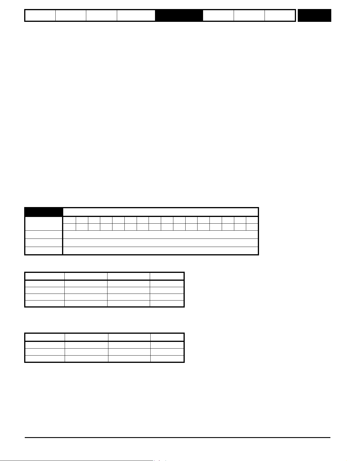
Parameter
structure
Keypad and
display
Parameter x.00
Parameter
description format
Advanced parameter
descriptions
Serial comms
protocol
Electronic
nameplate
Performance
Menu 3
5, Fr.Servo: Incremental encoder with forward, reverse and commutation outputs, with or without marker pulse
The UVW commutation signals are used to define the motor position during the first 120° electrical rotation after the drive is powered-up or the
encoder is initialised. If the Drive encoder lines per rev (Pr 3.34) is set to zero the incremental signals are ignored and the drive can run with
commutation signals alone. A phase locked loop is used to smooth the feedback, but particularly at low speeds the motor movement includes a
significant ripple. Low speed loop gains should be used and the drive encoder filter (Pr 3.42) should be set to 16 ms.
6, SC: SinCos: Encoder with no serial communications
A phasing test must be performed after every drive power-up or encoder trip.
7, SC.Hiper: Absolute SinCos encoder using Stegmann 485 comms protocol (HiperFace).
This type of encoder gives absolute position and can be used for motor control. The drive can check the position from the sine and cosine
waveforms against the internal encoder position using serial communications and if an error occurs the drive initiates a trip. An applications or
fieldbus Solutions Module can communicate with the encoder via parameters that are not visible from the keypad or drive 485 comms.
8, EnDAt: Absolute EnDat only encoder
This type of encoder gives absolute position and can be used for motor control. Additional communications with the encoder from an applications
or fieldbus module is not possible
9, SC.Endat: Absolute SinCos encoder using EnDat comms protocol
This type of encoder gives absolute position and can be used for motor control. The drive can check the position from the sine and cosine
waveforms against the internal encoder position using serial communications and if an error occurs the drive initiates a trip. An applications or
fieldbus Solutions Module can communicate with the encoder via parameters that are not visible from the keypad or drive 485 comms
10, SSI: Absolute SSI only encoder
This type of encoder gives absolute position and can be used for motor control. Additional communications with the encoder from an applications
or fieldbus module is not possible. SSI encoders use either gray code or binary format which can be selected with Pr 3.41.
11, SC.SSI: SinCos encoder using SSI comms protocol
This type of encoder gives absolute position and can be used for motor control. The drive can check the position from the sine and cosine
waveforms against the internal encoder position using serial communications and if an error occurs the drive initiates a trip.
All SINCOS encoders and encoders using communications must be initialized before their position data can be used. The encoder is automatically
initialized at power-up, after trips EnC1 to EnC8 or Enc11 to Enc17 are reset, and when the initialization (Pr 3.47) is set to 1. If the encoder is not
initialized or the initialization is invalid the drive initiates trip EnC7.
3.39
Coding
Drive encoder termination select / Rotary encoder select / Comms only encoder mode
Bit SP FI DE Txt VM DP ND RA NC NV PT US RW BU PS
11
Range 0 to 2
Default 1
Update rate Background read
Ab, Fd, Fr, Ab Servo, Fd Servo, Fr Servo - Drive encoder termination select
The terminations may be enabled/disabled by this parameter as follows:
Encoder input Pr 3.39=0 Pr 3.39=1 Pr 3.39=2
A-A\ Disabled Enabled Enabled
B-B\ Disabled Enabled Enabled
Z-Z\ Disabled Disabled Enabled
U-U\, V-V\, W-W\ Enabled Enabled Enabled
SC - Drive encoder termination select
The terminations may be enabled/disabled by this parameter as follows:
Encoder input Pr 3.39=0 Pr 3.39=1 Pr 3.39=2
A-A\ Disabled Enabled Enabled
B-B\ Disabled Enabled Enabled
Z-Z\ Disabled Disabled Enabled
SC.Hiper, SC.EnDat, SC.SSI - Rotary encoder select
If Pr 3.39 is set to 1 or 2 the encoder is a rotary encoder and the following apply:
1. Pr 3.33 defines the number of turns bits in the comms message from the encoder and a mask is applied to Pr 3.28 to remove turns bits in excess
of those provided in the encoder comms position.
2. The number of encoder lines per revolution defined by Pr 3.34 is forced to a power of two between 2 and 32768.
3. Pr 3.35 defines the number of comms bits used to define a single turn.
Digitax ST Advanced User Guide 57
Issue Number: 3
Page 58

Menu 3
Parameter
structure
Keypad and
display
Parameter x.00
Parameter
description format
Advanced parameter
descriptions
Serial comms
protocol
Electronic
nameplate
Performance
If Pr 3.39 is set to 0 the encoder is a linear encoder and the following apply:
1. Pr 3.33 defines the ratio between the length of a sine wave period and the length of the least significant comms bit.
2. No mask is applied to the turns displayed in Pr 3.28.
3. Pr 3.35 defines the number of comms bits used to give the whole position value.
If the position feedback device is SC.Hiper or SC.EnDat it is possible for the drive to set up this parameter automatically from information obtained
from the encoder (see Pr 3.41).
EnDat, SSI - Comms only encoder mode
If this parameter is set to 1 or 2 the drive always takes the complete absolute position for these comms only type encoders. The turns (Pr 3.28),
position (Pr 3.29) and fine position (Pr 3.30) will be an exact representation of the position from the encoder. If the encoder does not provide 16bits of
turns information, the internal representation of the turns used by the position controller in Menu 13 and functions within the SM-Applications Module
such as the Advanced Position Controller, rolls over at the maximum position value from the encoder. This jump in position is likely to cause unwanted
effects. As the SSI format does not include any error checking it is not possible for the drive to detect if the position data has been corrupted by noise
on the encoder signals. The benefit of using the absolute position directly from an SSI encoder is that even if the encoder communications are
disturbed by noise and position errors occur, the position will always recover the correct position after the disturbance has ceased. The EnDat format
includes a CRC that is used by the drive to detect corrupted data, and so if the position data has been corrupted the drive uses the previous correct
data until new uncorrupted data is received.
It should be noted that if the encoder does not provide at least 6 bits of turns information the speed feedback used to generate the drive over speed
trip is incorrect when the position rolls over or under the maximum value. Therefore this mode should not be used with encoders that do not provide
this turns information unless the encoder is not going to pass through the maximum position.
If this parameter is set to 0 the drive only takes the absolute position directly from the encoder during initialization. The change of position over each
sample is then used to determine the current position. This method always gives 16 bits of turns information that can be used without jumps in
position by the position controller in Menu13 and SM-Applications modules etc. This method will only operate correctly if the change of position over
any 250 μs period is less than 0.5 of a turn, or else the turns information will be incorrect. The turns can then only be corrected by re-initializing the
encoder. Under normal operating conditions and at a maximum speed of 40,000 rpm the maximum change of position is less than 0.5 turns, however,
if noise corrupts the data from an SSI encoder it is possible to have apparent large change of position, and this can result in the turns information
becoming and remaining corrupted until the encoder is re-initialized. This problem should not occur with EnDat encoders because three consecutive
corrupted messages at the slowest sample rate (i.e. 25 μs) would be required even at the maximum speed of 40,000 rpm before the change of
position would be the required 0.5 turns to give possible corruption of the turns information. If three consecutive messages with CRC errors occur this
will cause the drive to produce an EnC5 trip. The drive can only be re-enabled after the trip is reset which will re-initialize the encoder and correct the
absolute turns.
If an SSI encoder is used, but is not powered from the drive, and the encoder is powered up after the drive, it is possible tha
t the first change of
position detected could be large enough to cause the problem described above. This can be avoided if the encoder interface is initialized via Pr 3.47
after the encoder has powered up. If the encoder includes a bit that indicates the status of the power supply the power supply monitor should be
enabled (see Pr 3.40). This will ensure that the drive remains tripped until the encoder is powered up and the action of resetting the trip will re-initialize
the encoder interface.
If the position feedback device is EnDat it is possible for the drive to set up this parameter automatically from information obtained from the encoder
(see Pr 3.41).
3.40
Coding
Drive encoder error detection level
Bit SP FI DE Txt VM DP ND RA NC NV PT US RW BU PS
Range 0 to 7
Default 1
Update rate Background read
Trips can be enabled/disabled using Pr 3.40 as follows.
Bit Function
0 Wire break detect
1 Phase error detect
2 SSI power supply bit monitor
111
58 Digitax ST Advanced User Guide
Issue Number: 3
Page 59

Parameter
structure
Keypad and
display
Parameter x.00
Parameter
description format
Advanced parameter
descriptions
Serial comms
protocol
Electronic
nameplate
Performance
Menu 3
Encoder trips
The following table shows trips that can be initiated that are related to the drive encoder feedback and whether they can be enabled and disabled by
Pr 3.40.
Encoders Reason for error Drive trip
All Power supply short circuit EnC1
Ab, Fd, Fr, Ab.Servo, Fd.Servo,
Fr.Servo,
SC, SC.Hiper, SC.EnDat, SC.SSI
Ab.Servo, Fd.Servo, Fr.Servo
SC.Hiper, SC.EnDat, SC.SSI
SC.Hiper, SC.EnDat, SC.SSI
EnDat
SSI
SC.Hiper, SC.EnDat, EnDat
SC.Hiper, SC.EnDat, EnDat
SSI, SC.SSI
SC, SC.Hiper, SC.EnDat,
SC.SSI, EnDat, SSI
SC.Hiper, SC.EnDat, EnDat
All
All
+Hardware wire-break detect on A, B and Z inputs
Software wire break detection on sine wave signals
There is no wire break detection on the U, V and W commutation inputs
+Phase error
+Sine/cosine phase error
Comms failure (timeout)
(2)
(3)
(5)
Comms failure (timeout) or transfer time too long
Comms transfer time is too long
Checksum/CRC error or SSI not ready at start of position transfer (i.e. data
input not one)
The encoder has indicated an error
+Power supply failure
initialization has failed due to a comms error. EnC7
Auto-configuration has been requested by changing Pr 3.41, but an
initialization has not occurred to perform auto-configuration.
Speed feedback selected from an option slot that does not have a position
feedback category Solutions Module installed
Incorrect encoder phasing
(4)
(1)
EnC2
EnC3
EnC4
EnC5
EnC6
EnC8
EnC9
EnC10
SC, SC.Hiper, SC.EnDat, SC.SSI Failure of analog position alignment during encoder initialization Enc11
SC.Hiper The encoder type could not be identified during auto-configuration Enc12
SC.EnDat, EnDat
SC.EnDat, EnDat
The number of encoder turns read from the encoder during autoconfiguration is not a power of 2
The number of bits defining the encoder position within a turn read from the
encoder during auto-configuration is too large.
Enc13
Enc14
The number of periods per revolution is either less than 1 or greater than
SC.Hiper, SC.EnDat, EnDat
50000 when read or calculated from the encoder data during auto-
Enc15
configuration.
SC.EnDat, EnDat The number of comms bits per period are larger than 255. Enc 16
SC.Hiper, SC.EnDat, EnDat
This is a rotary encoder (Pr 3.39=1 or 2) and the lines per revolution read
from this encoder are not a power of two.
Enc 17
+These trips can be enabled/disabled by Pr 3.40
1. If the terminations are not enabled on the A, B or Z inputs the wire break system will not operate. (Note that as default the Z input terminations
are disabled to disable wire break detection on this input). No wire break detection is provided on the U, V or W commutation signals.
2. Phase error for a servo type encoder is to detect that the incremental pulses have been counted incorrectly. The error is detected if the
incremental position moves by 10° with respect to the position defined by the UVW commutation signals. The trip is initiated if the error is
detected for 10 consecutive samples.
3. Phase error for SinCos encoders with comms is detected by interrogating the encoder every second via comms to compare the incremental
position determined from the sine waves with the incremental position via comms. If the error is greater than 10° for 10 consecutive samples the
trip is initiated. It should be noted that this system should not be used where 180 x Pr 5.11 (or Pr 21.11 for motor map 2) / Pr 3.34 is greater than
10° or else incorrect EnC3 trips will occur.
4. Incorrect encoder phasing is detected if the motor reaches half of the speed defined by SPEED_REF_MAX and the phasing error is larger
enough for the motor to accelerate uncontrollably. It can be disabled by setting Pr 3.08 to any value greater than zero.
5. This trip can also be caused when data is transferred between the encoder and a Solutions Module, such as an SM-Applications module, and an
error other than those covered by EnC5 or EnC6 occurs.
Digitax ST Advanced User Guide 59
Issue Number: 3
Page 60

Menu 3
Parameter
structure
Keypad and
display
Parameter x.00
Parameter
description format
Advanced parameter
descriptions
Serial comms
protocol
Electronic
nameplate
Performance
Wire-break detection
It may be important to detect a break in the connections between the drive and the position feedback device. This feature is provided for most
encoder types either directly or indirectly as listed below.
Device Detection method Drive Trip
Ab, Fd, Fr, Ab.Servo,
Fd.Servo, Fr.Servo
SC,
SC.Hiper,
SC.EnData,
SC.SSI
SC.Hiper, SC.EnDat, EnDat
Hardware detectors on the A(F), B(D,R) and Z signal detect a wire
break.
The differential levels of the sine and cosine waveforms are
available to the drive. The drive detects wire break if Sine
2
+Cosine2
is less than the value produced by two valid waveforms with a
differential peak to peak magnitude of 0.25 V (1/4 of the nominal
level). This detects wire break in the sine and cosine connections.
Wire break in the comms jumper (link) is detected by a CRC or
timeout error.
EnC2
EnC2
EnC4, EnC5
Wire break detection is difficult with these devices. However, if
power supply monitoring is enabled the drive will be looking for a
SSI
one at the start of the message and a zero to indicate that the power
supply is okay. If the clock stops or the data line is disconnected the
EnC5, EnC6
data input to the drive may stay in one state or the other and cause a
trip.
Encoder initialization
Encoder initialization will occur as follows: at drive power-up, when requested by the user via Pr 3.47, when trips PS.24V or EnC1 to EnC8 or Enc11
to Enc17 are reset. initialization causes an encoder with comms to be re-initialized and auto-configuration to be performed if selected. After
initialization Ab.Servo, Fd.Servo and Fr.Servo encoders will use the UVW commutations signals to give position feedback for the first 120° (electrical)
of rotation when the motor is restarted.
A delay is provided during initialization for some encoders to allow the encoder to be ready to provide position information after it has powered up.
The delay is provided during initialization because this occurs during drive power-up and after encoder power supply trips are reset. The delays are as
follows:
Encoder type Initialization delay
Ab, Fd, Fr, Ab.Servo,
Fd.Servo, Fr.Servo
SC.Hiper
None
150 ms, then encoder reset, then 150
ms
SC.EnDat, EnDat 1.0 s
All other types 1.2 s
Encoder power supply trips
The encoder power supply from the drive can be switched off by the drive either because the encoder power supply is overloaded (EnC1 trip) or
because the internal 24 V supply within the drive is overloaded (PS.24V trip). The internal 24 V supply provides power for the encoder power supply,
user 24 V output, digital I/O, Solutions Modules etc. To ensure that an EnC1 trip is not initiated when the internal 24 V is overloaded, and
subsequently switched off by the drive, there is a delay of 40 ms in the detection of EnC1 trip. It is possible for other encoder trips such as wire break
detection (EnC2) to occur when the power supply is removed from the encoder. Therefore overloading the internal 24 V supply or the encoder supply
could result in an immediate EnC2 trip. To ensure that the correct reason for the trip is given PS.24V and EnC1 trips override an existing EnC2 to
EnC8 or Enc11 trip. This means that both the original trip (EnC2 to EnC8 or Enc11) and then the new trip (PS.24V or EnC1) are stored in the trip log.
3.41
Coding
Drive encoder auto configuration enable / SSI binary format select
Bit SP FI DE Txt VM DP ND RA NC NV PT US RW BU PS
1111
Default 0
Update rate Background read
SC.Hiper, SC.EnDat, EnDat
When a SC.Hiper, SC.EnDat or EnDat encoder is being used, the drive will interrogate the encoder on power-up. If Pr 3.41 is set to one and the
encoder type is recognized based on the information provided by the encoder, the drive will set the encoder turns / linear encoder comms to sine
wave ratio (Pr 3.33), the equivalent lines per revolution (Pr 3.34) and the encoder comms resolution / linear encoder comms bits (Pr 3.35). For
SC.Hiper or SC.EnDat encoders the rotary encoder select (Pr 3.39) is also set up. If the encoder is not recognized, there is a comms error or the
resulting parameter values are out of range the drive initiates an EnC7 or Enc12 to Enc17 trip to prompt the user to enter the information. The drive
can auto-configure with any of the following devices.
Rotary EnDat encoders
The encoder turns, comms resolution and equivalent lines per rev are set up directly using the data read from the encoder.
60 Digitax ST Advanced User Guide
Issue Number: 3
Page 61

Parameter
structure
Keypad and
display
Parameter x.00
Parameter
description format
Advanced parameter
descriptions
Serial comms
protocol
Electronic
nameplate
Performance
Menu 3
Linear EnDat encoders
The comms resolution is set to the number of bits required for the whole position within the position data messages from the encoder. The linear
encoder comms to sine wave ratio is calculated from the sine wave period and LS comms bit length. The encoder does not give the equivalent lines
per rev directly, but gives the length of a sinewave period in nm. Therefore the drive uses the pole pitch (Pr 5.36 or 21.31) and the number of motor
poles (Pr 5.11 or 21.11) for the current active motor (defined by Pr 11.45) to calculate the equivalent lines per revolution.
ELPR = Pole pitch x Number of motor pole pairs / Length of a sinewave
Normally the Number of motor poles will be set to 2, and so
ELPR = Pole pitch / Length of a sinewave
It should be noted that the equivalent lines per rev parameter is only updated when auto-configuration occurs, i.e. when the encoder is initialized, and
that it uses the pole pitch for the currently active motor. The value for Pole pitch x Number of motor pole pairs is limited to 655.35mm by the drive. If
the pole pitch is left at its default value of zero which would give ELPR = 0, or the result of the calculation is over 50000, the drive will initiate an Enc15
trip.
Rotary hiperface encoders
The drive can recognize any of the following devices: SCS 60/70, SCM 60/70, SRS 50/60, SRM 50/60, SHS 170, SCS-KIT 101, SKS36, SKM36. If
the drive cannot recognize the encoder type it will initiate Enc12 trip.
Linear Hiperface encoders
The drive can recognize the LINCODER. The calculations used for linear EnDat encoders are also used to determine the equivalent lines per
revolution. However, the length of a sine wave is fixed at 5mm.
EnDat encoders
If the encoder type is EnDat comms only then after auto-configuration Pr 3.39 is set to zero if the number of turns bits is less than 6. This
automatically selects absolute mode and prevents over speed trips at the encoder roll-over points which would otherwise occur.
SSI, SC.SSI
SSI encoders normally use gray code data format. However, some encoders use binary format which may be selected by setting this parameter to
one.
3.42
Coding
Drive encoder filter
Bit SP FI DE Txt VM DP ND RA NC NV PT US RW BU PS
111
Range 0 to 5 (0 to16 ms)
Default 0
Update rate Background read
0 = 0 ms, 1 = 1 ms, 2 = 2 ms, 3 = 4 ms, 4 = 8 ms, 5 = 16 ms
A sliding window filter may be applied to the feedback taken from the drive encoder. This is particularly useful in applications where the drive encoder
is used to give speed feedback for the speed controller and where the load includes a high inertia, and so the speed controller gains are very high.
Under these conditions, without a filter on the feedback, it is possible for the speed loop output to change constantly from one current limit to the other
and lock the integral term of the speed controller.
3.43
Coding
Maximum drive encoder reference
Bit SP FI DE Txt VM DP ND RA NC NV PT US RW BU PS
111
Range 0 to 40,000 rpm
Default 3,000
Update rate Background read
3.44
Coding
Drive encoder reference scaling
Bit SP FI DE Txt VM DP ND RA NC NV PT US RW BU PS
3 111
Range 0.000 to 4.000
Default 1.000
Update rate Background read
3.45
Coding
Drive encoder reference
Bit SP FI DE Txt VM DP ND RA NC NV PT US RW BU PS
1111
Range ±100.0 %
Update rate 4ms write
Digitax ST Advanced User Guide 61
Issue Number: 3
Page 62

Menu 3
Parameter
structure
Keypad and
display
Parameter x.00
Parameter
description format
Advanced parameter
descriptions
Serial comms
protocol
Electronic
nameplate
Performance
3.46
Coding
Drive encoder reference destination
Bit SP FI DE Txt VM DP ND RA NC NV PT US RW BU PS
1 2 1111
Range Pr 0.00 to Pr 21.50
Default Pr 0.00
Update rate Read on reset
The drive encoder input can be used as a reference to control a drive parameter. The drive encoder reference parameter (Pr 3.45) gives the speed of
the encoder input as a percentage of the maximum drive encoder reference provided that the number of encoder lines per revolution (Pr 3.34) has
been set up correctly. This may then be scaled and routed to any non-protected drive parameter.
3.47 Re-initialize position feedback
Coding
Bit SP FI DE Txt VM DP ND RA NC NV PT US RW BU PS
111
Update rate Background read
3.48 Position feedback initialized
Coding
Bit SP FI DE Txt VM DP ND RA NC NV PT US RW BU PS
1 111
Update rate Background write
At power-up Pr 3.48 is initially zero, but is set to one when the drive encoder and any encoders connected to position category modules have been
initialized. The drive cannot be enabled until this parameter is one.
If any trips occur that could indicate that the encoder system is no longer initialized correctly (i.e. EnC2-EnC8 and Enc11-Enc17), or the internal 24 V
or encoder power supplies are overloaded (i.e. EnC1 or PS.24V), Pr 3.48 is set to zero and the drive cannot be enabled until the encoder is reinitialized. It is likely that the failure of either of these supplies will cause one of the other encoder trips and it should be noted that EnC1 or PS.24V
trips can override EnC2-EnC8 and Enc11-Enc17 trips so that the power supply overload is not mistaken for an encoder error.
3.49 Full motor object electronic nameplate transfer
Coding
Bit SP FI DE Txt VM DP ND RA NC NV PT US RW BU PS
111
Default 0
Update rate Read on reset
When this parameter is set to one, additional information for the motor object can be transferred from Pr 18.11 to Pr 18.17 as shown below.
User parameter Motor object parameter
Pr 18.11 Motor object version number
Pr 18.12 Motor type (MSW)
Pr 18.13 Motor type (LSW)
Pr 18.14 Motor manufacturer
Pr 18.15 Motor serial number (MSW)
Pr 18.16 Motor serial number
Pr 18.17 Motor serial number (LSW)
3.50 Position feedback lock
Coding
Bit SP FI DE Txt VM DP ND RA NC NV PT US RW BU PS
111
Default 0
Update rate 4 ms read
If Pr 3.50 is set to one Pr 3.28, Pr 3.29 and Pr 3.30 are not updated. If this parameter is set to zero these parameters are updated normally.
62 Digitax ST Advanced User Guide
Issue Number: 3
Page 63

Parameter
structure
Keypad and
display
Parameter x.00
Parameter
description format
Advanced parameter
descriptions
Serial comms
protocol
Electronic
nameplate
Performance
Menu 3
3.52
Coding
Encoder simulation ratio numerator
Bit SP FI DE Txt VM DP ND RA NC NV PT US RW BU PS
4 111
Range 0.0000 to 1.0000
Default 1.0000
Update rate Background read
The encoder simulation source is the drive encoder input and can be any incremental type or any SINCOS type. If a SINCOS is used as the source
the simulation output is derived from the zero crossings of the sine waves and does not include interpolated information. The encoder simulation
provides an output with minimal delay from the drive encoder input. The ratio between the change of drive encoder position and the change of
encoder simulation output position is defined by Pr 3.52. The table below shows the possible ratios.
Pr 3.52 Ratio
0.0000 to 0.0312 1/32
0.0313 to 0.0625 1/16
0.0626 to 0.1250 1/8
0.1251 to 0.2500 1/4
0.2501 to 0.5000 1/2
0.5001 to 1.0000 1
3.54
Coding
Encoder simulation mode
Bit SP FI DE Txt VM DP ND RA NC NV PT US RW BU PS
1 111
Range 0 to 4
Default 0
Update rate Background read
Pr 3.54 selects the format of the encoder simulation output as shown in the table below.
03.54 String Mode
0 Ab Quadrature outputs
1 Fd Frequency and direction outputs
2 Fr Forward and reverse outputs
3 Ab.L Quadrature outputs with marker lock
4 Fd.L Frequency and direction outputs with marker lock
The marker output is derived directly from the encoder simulation input source marker. The width of the marker pulse is not adjusted with the encoder
simulation ratio, but remains the same width as the input marker. If a mode without marker lock is selected then the relationship between the marker
position and the incremental signals is undefined. If a mode with marker lock is selected the incremental position is shifted when the first input marker
occurs so that with Ab mode the marker is aligned with A high and B high, and with Fd mode the marker is aligned with F high. Marker lock is required
when the system that is receiving the encoder simulation signals requires a defined relationship between the marker and the incremental signals.
Marker lock should not be used if the drive encoder equivalent lines per revolution (ELPR) is not a power of 2 or the ELPR of the encoder simulation
output is less than 1 after the divide ratio has been applied.
5.5.1 Communication with Hiperface and EnDat encoders
It is possible to use the communications channel between the drive and a Hiperface or EnDat encoder. This allows access to the encoder functions
including reading the encoder position and, reading and writing to encoder memory. The system can be used to communicate with SC.Hiper and
SC.EnDat type encoders provided that the position checking system has been disabled, by setting Pr 90.21 to one.
To send a message to the encoder the required message must be written to the transmit register (Pr 90.22). To read the response from the encoder
the data is read from the receive register (Pr 90.23).
Digitax ST Advanced User Guide 63
Issue Number: 3
Page 64

Menu 3
Parameter
structure
Keypad and
display
Parameter x.00
Parameter
description format
Advanced parameter
descriptions
Serial comms
protocol
Electronic
nameplate
Performance
Bits 13-15 of the registers are used to indicate the following:
Register Bit Function
Transmit 15 Must be set for the drive to transfer the LS byte to the comms buffer.
Transmit 14
Transmit 13
The LS byte is the last byte of the message and this byte should be put in the comms buffer and be
transferred to the encoder.
The LS byte is the first byte of the message. (If this is used the buffer pointer is reset to the start of
the buffer.)
Receive 15 Indicates data from the last transfer can be read from the receive buffer.
Receive 14 The byte in the LS byte is the last byte of the receive message
There is no data in the receive buffer and the LS byte is the comms system status. If there was an
Receive 13
error in the received message this will always be set and one of the status error bits will be set until
the comms is used again by this system or by the drive.
Data should be written to the transmit register (Pr 90.22) when the register has been reset to zero by the drive. The data will be transferred to the
comms buffer and the transmit register will be cleared.
Data can be read from the receive register (Pr 90.23) at any time. If there is receive data in the buffer bit 15 will be set. Once the data has been read
the register should be cleared and the drive will then transfer more data.
The actual encoder comms buffer is 16 bytes long and any messages that exceed this length (including the checksum added for Hiperface) will cause
an error. The status flags are defined as follows:
Bit Meaning
The number of bytes put into the transmit buffer is not consistent with the expected message length.
0
(Hiperface only)
The number of bytes written to the transmit buffer, or the expected length of the store data transmit message, or the
1
expected length of a read data message have exceed the length of the buffer.
(Hiperface only)
2 The command code is not supported.
3 The encoder has signalled an error.
4 There was an error in the checksum/CRC of the received message.
5 A timeout occurred.
SC.Hiper type encoders
The Stegmann Hiperface comms protocol is an asynchronous byte based system. Up to 15 bytes of data can be written to the buffer. The first byte
should be the encoder address. The checksum will be calculated by the drive and added to the end of the message before the message is transmitted
to the encoder. The drive checks the checksum of the received message. If successfully received, the receive message can be read via the receive
register (Pr 90.23) including the address and the checksum received from the encoder. It should be noted that the encoder must be set up for 9600
baud, 1 start bit, 1 stop bit and even parity (default set-up) for the encoder comms to operate with the drive. Also the data block security should not be
enabled in the encoder if the drive encoder nameplate system is to operate correctly.
The following commands are supported:
Code Command
0x42 Read position
0x43 Set position
0x44 Read analog value
0x46 Read counter
0x47 Increment counter
0x49 Clear counter
0x4a Read data (maximum of 10 bytes)
0x4b Store data (maximum of 9 bytes)
0x4c Data field status
0x4d Create a data field
0x4e Available memory
0x50 Read encoder status
0x52 Read type
0x53 Reset encoder
Example of a Hiperface transfer: read position
Disable drive encoder position check by setting Pr 90.21 to one. This should be set back to zero at the end of the transfer if encoder position checking
is required.
Transfer the "read position" message to the encoder comms buffer by writing the sequence of words shown in the table below to Pr 90.22. A check
should be carried out before each word is written to ensure that the parameter is zero (i.e. the drive has taken any previous data).
64 Digitax ST Advanced User Guide
Issue Number: 3
Page 65

Parameter
structure
Keypad and
display
Parameter x.00
Parameter
description format
Advanced parameter
descriptions
Serial comms
protocol
Electronic
nameplate
Performance
Menu 3
Bit 15 Bit 14 Bit 13 Data
0xa0ff 1 0 1 0xff Broadcast message so address = 0xff
0xc042 1 1 0 0x42 Read position command
As bit 14 of the second word is set to one the drive will add the checksum and transfer this message to the encoder. When the encoder response has
been received by the drive the first byte of the message will be placed in the least significant byte of Pr 90.23 and bit 15 will be set to one. This data
should be read and the parameter cleared so that the drive will put the next byte into this parameter. The sequence of data that should appear in
Pr 90.23 for an encoder with an address of 0x40 and a position of 0x03, 0x59, 0x63, 0x97 is shown in the table below.
Bit 15 Bit 14 Bit 13 Data
0x8040 1 0 0 0x40 Encoder address
0x8042 1 0 0 0x42 Read position command
0x8003 1 0 0 0x03 Position byte 0 (MS byte)
0x8059 1 0 0 0x59 Position byte 1
0x8063 1 0 0 0x63 Position byte 2
0x8097 1 0 0 0x97 Position byte 3 (LS byte)
0xc0ac 1 1 0 0xac Checksum
Example of Hiperface transfer: Delete data field
Transfer the "delete data field" message to the encoder comms buffer by writing the sequence of words shown in the table below to Pr 90.22. A check
should be carried out before each word is written to ensure that the parameter is zero (i.e. the drive has taken any previous data).
Bit 15 Bit 14 Bit 13 Data
0xa0ff 1 0 1 0xff Broadcast message so address = 0xff
0x804d 1 0 0 0x4d Create data field command
0x8002 1 0 0 0x02 Data field 2
0x8065 1 0 0 0x65
Status of data existing data field 2 with bit 7
set to zero
0x8055 1 1 0 0x55 Code for data field at default of 0x55
The response from the encoder is a follows.
Bit 15 Bit 14 Bit 13 Data
0x8040 1 0 0 0x40 Encoder address
0x8042 1 0 0 0x4d Create data field command
0x8003 1 0 0 0x02 Data field 2
0x8059 1 0 0 0x65 Status of the data field before delete
0x8063 1 1 0 0x78 Checksum
SC.EnDat
The Heidenhain EnDat protocol is a synchronous protocol using the following command message format (drive to encoder).
Command
st
byte
1
Address
Data (LSB)
Data (MSB)
th
byte
4
The following commands are supported:
Code Command Address Data
0x00 Encoder to send position Don’t care Don’t care
0x01 Selection of memory area MRS code Don’t care
0x03 Encoder to receive parameter Address Data
0x04 Encoder to send parameter Address Don’t care
0x05 Encoder to receive reset Don’t care Don’t care
Digitax ST Advanced User Guide 65
Issue Number: 3
Page 66

Menu 3
Parameter
structure
Keypad and
display
Parameter x.00
Parameter
description format
Advanced parameter
descriptions
Serial comms
protocol
Electronic
nameplate
Performance
The following is an example of the response when the Encoder to send position command is used (encoder to drive).
LS byte
1
st
byte
Bits 7-0 = 0
Bits 7-0 = 0
Bits 7-0 = 0
Bits 7-0 = 0
Bits 5-0 = 0
Bits 6 = Alarm bit
Bits 7 = Bit 0 of position
Bits 7-0 = Bits 8-1 of position
Bits 3-0 = Bits 12-9 of position
Bits 7-4 = Bits 3-0 of turns
MS byte
8
th
byte
Bits 7-0 = Bits 11-4 of turns
The example shown above is for an encoder with 12 bits representing the turns and 13 bits representing the position within a turn. The position
command only requires one byte to be sent to the encoder. Bits 14 and 13 can both be set in the transmit register if required to indicate that this is
both the first and last byte of the message.
If any other command is used then the response is as follows (encoder to drive).
Address
1
st
byte
Data (LSB)
Data (MSB)
rd
byte
3
Example of EnDat transfer: Read position
Disable drive encoder position check by setting Pr 90.21 to one. This should be set back to zero at the end of the transfer if encoder position checking
is required.
Transfer the "read position" message to the encoder comms buffer by writing the sequence of words shown in the table below to Pr 90.22. A check
should be carried out before each word is written to ensure that the parameter is zero (i.e. the drive has taken any previous data).
Bit 15 Bit 14 Bit 13 Data
0xa000 1 0 1 0x00 Read position command
0xc000 1 1 0 0x00 Address
The second word contains the address which is not required for the command, but has been passed to the drive so that a word with bit 14 set to one
is received by the drive to initiate the data transfer to the encoder. When the encoder response has been received by the drive the first byte of the
message will be placed in the least significant byte of Pr 90.23 and bit 15 will be set to one. This data should be read and the parameter cleared so
that the drive will put the next byte into this parameter. The sequence of data that could appear in Pr 90.23 for an encoder with 12 turns bits and 13
position bits is shown in the table below.
Bit 15 Bit 14 Bit 13 Data
0x8000 1 0 0 0x00
0x8000 1 0 0 0x00
0x8000 1 0 0 0x00
0x8000 1 0 0 0x00
0x8000 1 0 0 0x00 Bit7 = bit 0 of position, Bit6 = alarm bit
0x809f 1 0 0 0x9f Bits 8-1 of position
0x804e 1 0 0 0x4e Bits 3-0 of turns and 12-9 of position
0xc074 1 1 0 0x74 Bits 11-4 of turns
Turns = 0111 0100 0100 = 0x744
Position = 1 1101 0011 1110 = 0x1d3e
Alarm bit = 0
Example of EnDat transfer: Encoder send parameter
Data written to Pr 90.22
Bit 15 Bit 14 Bit 13 Data
0xa004 1 0 1 0x04 Encoder to send parameter command
0x8000 1 0 0 0x00 Address zero
0x8000 1 0 0 0x00 Data (not required)
0xc000 1 1 0 0x00 Data (not required)
66 Digitax ST Advanced User Guide
Issue Number: 3
Page 67

Parameter
structure
Keypad and
display
Parameter x.00
Parameter
description format
Data read from Pr 90.23
Bit 15 Bit 14 Bit 13 Data
0x8000 1 0 0 0x00 Address
0x8012 1 0 0 0x12 Data
0x8034 1 1 0 0x34 Data
The data in the parameter at address zero is 0x1234.
Advanced parameter
descriptions
Serial comms
protocol
Electronic
nameplate
Performance
Menu 3
Digitax ST Advanced User Guide 67
Issue Number: 3
Page 68

Menu 4
Rsi
sy
wmrσ
Lsi
sy
v
s
Rotor flux
i
s
vϕ
CURRENT_LIMIT_MAX
Maximum current
Motor rated current
-------------------------------------------------------
100%×=
Parameter
structure
Keypad and
display
Parameter x.00
Parameter
description format
Advanced parameter
descriptions
Serial comms
protocol
Electronic
nameplate
Performance
5.6 Menu 4: Torque and current control
The scaling of the current feedback is based on the rating of the drive as follows:
Level x Current scaling (Kc) x Maximum current rating
Over-current trip 1/0.45 = 2.22 3.81
Maximum standard operating current 1.75 3.00
Current scaling (Kc) 1.0 1.72
Maximum current rating 0.581 1.0
Current scaling (Kc) is 1 per unit current and is related to the scaling of the drive current feedback. Kc is greater than the Maximum current rating
defined by Pr 11.32 . The Maximum current rating is the maximum value of rated motor current (defined by Pr 5.07 or Pr 21.07) that can be set. The
limit up to which the drive can control current normally is the Maximum standard operating current or 1.75 x Kc. The current range above this is
allowed for current controller overshoot and for additional current feedback pulses associated with long cable operation.
The Maximum standard operating current is 1.75 x Kc which allows for an overload based on the Maximum current rating of 300 %.
The table below gives the current scaling (Kc) and Maximum current rating for all drive sizes and voltage ratings.
Table 5-3 Current ratings
200V 400V
Model Current scaling (Kc) Max current rating Model Current scaling (Kc) Max current rating
DST1201 2.92 1.70 DST1401 2.58 1.50
DST1202 6.52 3.80 DST1402 4.63 2.70
DST1203 9.26 5.40 DST1403 6.86 4.00
DST1204 13.03 7.60 DST1404 10.12 5.90
DST1405 13.72 8.00
The drive operates in the rotor flux reference frame. The maximum normal operating current is controlled by the current limits.
DRIVE_CURRENT_MAX is full scale current feedback, i.e. Kc / 0.45.
The relationship between the voltage and current is shown in the following vector diagram.
Definitions:
vs = motor terminal voltage vector
i
= motor current vector
s
V
ϕ = voltage produced by the rotor magnets
MOTOR1_CURRENT_LIMIT_MAX is used as the maximum for some parameters such as the user current limits. The current maximum current limit
is defined as follows (with a maximum of 1000%):
Where:
Motor rated current is given by Pr 5.07
(MOTOR2_CURRENT_LIMIT_MAX is calculated from the motor map 2 parameters)
The Maximum current is (1.75 x Kc)
The rated active and rated magnetising currents are calculated from motor rated current (Pr 5.07) as:
rated active current = motor rated current
rated magnetising current = 0
68 Digitax ST Advanced User Guide
Issue Number: 3
Page 69

Parameter
CURRENT_LIMIT_MAX
Maximum current
Motor rated current
-------------------------------------------------------
100 %×=
1.75 x Kc
8A
--------------------------
100 %×=
1.75 x 17.32 A
8A
---------------------------------------
100 %×=
300 %=
4.04
Current
demand
Filter
+
_
4.08
4.09
10.0910.08
4.13
4.14
Current loop
P gain
Current loop
I gain
Current controller
4.18
11.32
5.07
4.05
4.06
Motoring
Regenerating
Current limits
4.07
Symmetrical
Drive rated
continuous
current
Motor rated
current
Over-riding
current limit
3.05
Zero
speed
threshold
Torque reference
offset
Torque
reference*
Speed
over-ride
level
Coiler/uncoiler
speed
over-ride
level
+
At 100%
load
indicator
Current limit
active
indicator
Motor active
current
4.02
10.174.19
Motor
overload
accumulator
Motor current
overload alarm
indicator
10.39
Braking energy
overload
indicator
Torque mode
selector
4.11
4.10
Torque
reference
offset
enable
+
0
1
2
3
4
+
+
4.03
Torque
demand
0.XX
0.XX
Key
Read-write (RW)
parameter
Read-only (RO)
parameter
Input
terminals
Output
terminals
X
X
X
X
Percentage
load
4.20
The parameters are all shown at their default settings
4.23
Current
demand
filter 1
4.12
Current
demand
filter 2
4.15 4.16
Motor thermal
time constant
Motor protection
mode
4.24
4.25
Low speed
protection mode
Overload detection
User current
max scaling
Speed controller
gain select
3.16
1.03
Preramp
reference
3.04
+
3.01
3.02
Speed
feedback
Final
speed
demand
_
Speed loop
output
+
+
4.22
2.38
Inertia
compensation
enable
+
Inertia
compensation
torque
structure
Keypad and
display
Parameter x.00
Parameter
description format
Advanced parameter
descriptions
Serial comms
protocol
Electronic
nameplate
Performance
Menu 4
Example:
Work out the available current limit for a DST1405 with a motor rated current of 8 A set in Pr 5.07 (i.e. equal to the Maximum current rating of the
drive).
From Table 5-3 above the Current scaling (Kc) value for a DST1405 is 13.72 A.
If the motor rated current is reduced then the maximum available current limit increases up to a maximum of 1000 %.
The drive only requires the motor rated current to set the maximum current limit correctly and scale the current limits, and so no auto-tuning is
required to set these accurately.
Figure 5-4 Menu 4 Logic diagram
Digitax ST Advanced User Guide 69
Issue Number: 3
Page 70

Menu 4
Pr
4.02
Resultant
output current
Pr
4.01
Pr
4.17
y
x
Parameter
structure
Keypad and
display
Parameter x.00
Parameter
description format
Advanced parameter
descriptions
Serial comms
protocol
Electronic
nameplate
Performance
4.01 Current magnitude
Coding
Bit SP FI DE Txt VM DP ND RA NC NV PT US RW BU PS
1 121 1 1 1
Range 0 to DRIVE_CURRENT_MAX A
Update rate 4ms write
This parameter is the r.m.s. current from each output phase of the drive. In normal operation with a permanent magnet servo motor, this parameter
shows the magnitude of the active current in Pr 4.02. When in the field weakening range, the phase currents consist of an active component and a
reactive component. The three phase currents can be combined to form a resultant current vector as shown below:
The resultant current magnitude is displayed by this parameter. The active current is the torque producing current for a motor drive. The reactive
current is the magnetizing or flux producing current.
4.02 Active current
Coding
Bit SP FI DE Txt VM DP ND RA NC NV PT US RW BU PS
112111
Range ±DRIVE_CURRENT_MAX A
Update rate 4ms write
The active current is the torque producing current.
Direction of active current Direction of rotation Torque direction
+ + Forward (accelerating)
- + Reverse (decelerating)
+ - Forward (decelerating)
- - Reverse (accelerating)
The active current is aligned with the y axis of the reference frame. The x axis of the reference frame is aligned with the rotor flux vector. The motor
torque is proportional to the torque producing current when field weakening is not active. Once field weakening is active the torque producing current
is boosted to compensate for the reduction in motor flux.
4.03 Torque demand
Coding
Bit SP FI DE Txt VM DP ND RA NC NV PT US RW BU PS
111111
Range ±TORQUE_PROD_CURRENT_MAX %
Update rate 4ms write
The torque demand can be derived from the speed controller and/or the torque reference and offset. The units of the torque demand are % of rated
torque. 100% rated torque is defined as the torque produced by 100% rated active current.
4.04 Current demand
Coding
Bit SP FI DE Txt VM DP ND RA NC NV PT US RW BU PS
111111
Range ±TORQUE_PROD_CURRENT_MAX %
Update rate 4ms write
The current demand is derived from the torque demand. Provided the motor is not field weakened the torque and current demands are the same. In
the field weakening range the current demand is increased with reduced flux. The level of flux is derived from the motor model within the drive
controllers.
Pr 4.04 = Pr 4.03 x flux / rated flux
70 Digitax ST Advanced User Guide
Issue Number: 3
Page 71

Parameter
structure
Keypad and
display
Parameter x.00
Parameter
description format
Advanced parameter
descriptions
Serial comms
protocol
Electronic
nameplate
Performance
Menu 4
4.05 Motoring current limit
Coding
Bit SP FI DE Txt VM DP ND RA NC NV PT US RW BU PS
11 1 111
Range 0 to MOTOR1_CURRENT_LIMIT_MAX %
Default 300.0
Second motor
parameter
Pr 21.27
Update rate Background read
4.06 Regen current limit
Coding
Bit SP FI DE Txt VM DP ND RA NC NV PT US RW BU PS
11 1 111
Range 0 to MOTOR1_CURRENT_LIMIT_MAX %
Default 300.0
Second motor
parameter
Pr 21.28
Update rate Background read
4.07 Symmetrical current limit
Coding
Bit SP FI DE Txt VM DP ND RA NC NV PT US RW BU PS
11 1 111
Range 0 to MOTOR1_CURRENT_LIMIT_MAX %
Default 300.0
Second motor
parameter
Pr 21.29
Update rate Background read
The motoring current limit applies in either direction of rotation when the machine is producing motoring torque. Similarly the regen current limit
applies in either direction when the machine is producing regenerating torque. The symmetrical current limit can override either motoring or
regenerating current limit if it is set at a lower value than either limit.
4.08 Torque reference
Coding
Bit SP FI DE Txt VM DP ND RA NC NV PT US RW BU PS
Range ±USER_CURRENT_MAX %
Default 0.00
Update rate 4ms read
4.09 Torque offset
Coding
Bit SP FI DE Txt VM DP ND RA NC NV PT US RW BU PS
Range ±USER_CURRENT_MAX %
Default 0.0
Update rate 4ms read
12 11
11 11
Digitax ST Advanced User Guide 71
Issue Number: 3
Page 72

Menu 4
Pr +
4.08
Pr (if enabled)
4.09
Pr
3.01
Speed
Current
+ final speed demand
+ resultant torque
- final speed demand
+ resultant torque
+ final speed demand
-resultant torque
- final speed demand
- resultant torque
Parameter
structure
Keypad and
display
Parameter x.00
Parameter
description format
Advanced parameter
descriptions
Serial comms
protocol
Electronic
nameplate
Performance
4.10 Torque offset select
Coding
Bit SP FI DE Txt VM DP ND RA NC NV PT US RW BU PS
111
Default 0
Update rate 4ms read
The torque offset is added to the torque reference when Pr 4.10 is one. The torque offset is updated every 4ms when connected to an analog input,
and so Pr 4.08 should be used for fast updating if required.
4.11 Torque mode selector
Coding
Bit SP FI DE Txt VM DP ND RA NC NV PT US RW BU PS
111
Range 0 to 4
Default 0
Update rate 4ms read
When this parameter is set to 1, 2 or 3 the ramps are not active while the drive is in the run state. When the drive is taken out of the run state, but not
disabled, the appropriate stopping mode is used. It is recommended that coast stopping or stopping without ramps are used. However, if ramp stop
mode is used the ramp output is pre-loaded with the actual speed at the changeover point to avoid unwanted jumps in the speed reference.
0: Speed control mode
The torque demand is equal to the speed loop output.
1: Torque control
The torque demand is given by the sum of the torque reference and the torque offset, if enabled. The speed is not limited in any way, however, the
drive will trip at the overspeed threshold if runaway occurs.
2: Torque control with speed override
The output of the speed loop defines the torque demand, but is limited between 0 and the resultant torque reference (Pr 4.08 + Pr 4.09 (if
enabled)). The effect is to produce an operating area as shown below if the final speed demand and the resultant torque reference are both
positive. The speed controller will try and accelerate the machine to the final speed demand level with a torque demand defined by the resultant
torque reference. However, the speed cannot exceed the reference because the required torque would be negative, and so it would be clamped
to zero.
Depending on the sign of the final speed demand and the resultant torque the four areas of operation shown below are possible.
This mode of operation can be used where torque control is required, but the maximum speed must be limited by the drive.
3: Coiler/uncoiler mode
Positive final speed demand: a positive resultant torque will give torque control with a positive speed limit defined by the final speed demand.
A negative resultant torque will give torque control with a negative speed limit of -5 rpm.
Negative final speed demand: a negative resultant torque will give torque control with a negative speed limit defined by the final speed demand.
A positive resultant torque will give torque control with a positive speed limit of +5 rpm.
72 Digitax ST Advanced User Guide
Issue Number: 3
Page 73

Parameter
Final speed
demand
Area for coiler operation, speed
limited to ref and positve torque
Area for decelerating the coiler, reverse
speed limited and negative torque
-5rpm
Speed
Torque
-5rpm
Area for normal uncoiler
operation: negative torque,
limited to low speed in reverse
Speed reference
Area for accelerating
uncoiler: positive torque,
limited speed
Speed
To rq u e
structure
Keypad and
display
Parameter x.00
Parameter
description format
Advanced parameter
descriptions
Serial comms
protocol
Electronic
nameplate
Performance
Menu 4
Example of coiler operation:
This is an example of a coiler operating in the positive direction. The final speed demand is set to a positive value just above the coiler reference
speed. If the resultant torque demand is positive the coiler operates with a limited speed, so that if the material breaks the speed does not exceed a
level just above the reference. It is also possible to decelerate the coiler with a negative resultant torque demand. The coiler will decelerate down to 5rpm until a stop is applied. The operating area is shown in the following diagram:
Example of uncoiler operation:
This is an example for an uncoiler operating in the positive direction. The final speed demand should be set to a level just above the maximum normal
speed. When the resultant torque demand is negative the uncoiler will apply tension and try and rotate at 5 rpm in reverse, and so take up any slack.
The uncoiler can operate at any positive speed applying tension. If it is necessary to accelerate the uncoiler a positive resultant torque demand is
used. The speed will be limited to the final speed demand. The operating area is the same as that for the coiler and is shown below:
4: Speed control with torque feed-forward
The drive operates under speed control, but a torque value may be added to the output of the speed controller. This can be used to improve the
regulation of systems where the speed loop gains need to be low for stability.
4.12 Current demand filter 1
Coding
Bit SP FI DE Txt VM DP ND RA NC NV PT US RW BU PS
1 111
Range 0.0 to 25.0 ms
Default 0.0
Update rate Background read
A first order filter, with a time constant defined by this parameter, is provided on the current demand to reduce acoustic noise and vibration produced
as a result of position feedback quantisation noise. The filter introduces a lag in the speed loop, and so the speed loop gains may need to be reduced
to maintain stability as the filter time constant is increased. Alternative time constants can be selected depending on the value of the speed controller
gain selector (Pr 3.16). If Pr 3.16 = 0 Pr 4.12 is used, if Pr 3.16 = 1 Pr 4.23 is used.
4.13 Current controller Kp gain
Coding
Bit SP FI DE Txt VM DP ND RA NC NV PT US RW BU PS
111
Range 0 to 30,000
Default
Second motor
parameter
Update rate Background read
200 V drive: 75
400 V drive: 150
Pr 21.22
Digitax ST Advanced User Guide 73
Issue Number: 3
Page 74

Menu 4
Parameter
structure
Keypad and
display
Parameter x.00
Parameter
description format
Advanced parameter
descriptions
Serial comms
protocol
Electronic
nameplate
Performance
4.14 Current controller Ki gain
Coding
Bit SP FI DE Txt VM DP ND RA NC NV PT US RW BU PS
111
Range 0 to 30,000
Default
Second motor
parameter
200 V drive: 1,000
400 V drive: 2,000
Pr 21.23
Update rate Background read
The proportional gain Kp (Pr 4.13) is the most critical value in controlling the performance of the current controllers. Either the value can be set by
auto-tuning (see Pr 5.12), or it can be set by the user so that
Kp = (L / T) x (Ifs / Vfs) x (256 / 5)
Where:
T is the sample time of the current controllers. The drive compensates for any change of sample time, and so it should be assumed that the
sample time is equivalent to the lowest sample rate of 167 μs.
L is the motor inductance. This is half the phase to phase inductance that is normally specified by the manufacturer. This is the inductance value
stored in Pr 5.24 after the auto-tune test is carried out.
I
is the peak full scale current feedback = Kc x √2 / 0.45. Where Kc is the current scaling for each size of drive.
fs
V
is the maximum DC bus voltage.
fs
Therefore:
Kp = (L / 167us) x (Kc x √2 / 0.45 / Vfs) x (256 / 5)
= K x L x Kc
Where:
K = √2 / (0.45 x V
x 167 μs) x (256 / 5)
fs
There is one value of the scaling factor K for each drive voltage rating as shown in the table below
Drive voltage
rating
V
fs
K
200 V 415 V 2,322
400 V 830 V 1,161
The integral gain Ki (Pr 4.14) is less critical and should be set so that
Ki = Kp x 256 x T /
τm
where
τ
is the motor time constant (L / R).
m
R is the per phase stator resistance of the motor (i.e. half the resistance measured between two phases).
Therefore
Ki = (K x L x Kc) x 256 x 167 us x R / L
= 0.0427 x K x R x Kc
The above equations give the gain values that are calculated by the auto-tune system and these should give the best response at all switching
frequencies with minimal overshoot. If required the gains can be adjusted to improve performance as follows:
1. The integral gain (Ki) can be used to improve the performance of the current controllers by reducing the effects of inverter non-linearity. These
effects become more significant with higher switching frequency. These effects will be more significant for drives with higher current ratings and
higher voltage ratings. If Ki is increased by a factor of 4 it is possible to get up to 10 % overshoot in response to a step change of current
reference. For high performance applications, it is recommended that Ki is increased by a factor of 4 from the auto-tuned values. As the inverter
non-linearity is worse with higher switching frequencies it is may be necessary to increase Ki by a factor of 8 for operation with 16 kHz switching
frequency.
2. It is possible to increase the proportional gain (Kp) to reduce the response time of the current controllers. If Kpi is increased by a factor of 1.5 then
the response to a step change of reference will give 12.5 % overshoot. It is recommended that Ki is increased in preference to Kpi.
As already stated, the drive compensates for changes of switching frequency to give similar performance as the switching frequency changes. The
following table gives the relationship between the user gain values and the values actually used by the drive.
74 Digitax ST Advanced User Guide
Issue Number: 3
Page 75

Parameter
I /(K*Motor Rated Current)
22
Te mp
C
R
structure
Keypad and
display
Parameter x.00
Parameter
description format
Advanced parameter
descriptions
Serial comms
protocol
Switching freq Proportional gain Integral gain
3 kHz Pr 4.13 Pr 4.14
4 kHz Pr 4.13 x 1.5 Pr 4.14
6 kHz Pr 4.13 x 2 Pr 4.14
8 kHz Pr 4.13 x 2 Pr 4.14 x 1.3
12 kHz Pr 4.13 x 2.6 Pr 4.14 x 1.3
4.15 Thermal time constant
Coding
Bit SP FI DE Txt VM DP ND RA NC NV PT US RW BU PS
111
Range 0.0 to 3000.0
Default 20.0
Second motor
parameter
Pr 21.16
Update rate Background read
4.16 Thermal protection mode
Coding
Bit SP FI DE Txt VM DP ND RA NC NV PT US RW BU PS
1111
Range 0 to 1
Default 0
Update rate Background read
The motor is modelled thermally in a way that is equivalent to the electrical circuit shown as follows.
Electronic
nameplate
Performance
Menu 4
The temperature of the motor as a percentage of maximum temperature, with a constant current magnitude of I, constant value of K and constant
value of motor rated current (set by Pr 5.07 or Pr 21.07) after time t is given by
2
Temp = [I
/ (K x Motor rated current)2] (1 - e
This assumes that the maximum allowed motor temperature is produced by K x Motor rated current and that τ is the thermal time constant of the point
in the motor that reaches its maximum allowed temperature first. τ is defined by Pr 4.15. The estimated motor temperature is given by Pr 4.19 as a
percentage of maximum temperature. If Pr 4.15 has a value between 0.0 and 1.0 the thermal time constant is taken as 1.0.
Pr 4.25 can be used to select 2 alternative protection characteristics (see diagram below). If Pr 4.25 is 0 the characteristic is for a motor which can
operate at rated current over the whole speed range. If Pr 4.25 is 1 the characteristic is intended for motors where the cooling effect of motor fan
reduces with reduced motor speed below half of rated speed. The maximum value for K is 1.05, so that above the knee of the characteristics the
motor can operate continuously up to 105 % current.
Digitax ST Advanced User Guide 75
Issue Number: 3
-t/τ
) x 100 %
Page 76

Menu 4
Motor total
current (Pr 4.01)
as a percentage
of motor rated
current
Motor speed as a
percentage of base speed
105%
Max. permissible
continuous
current
100%
70%
50%
Pr = 0
4.25
Pr = 1
4.25
t protection operates in this region
2
I
Proportion of rated speed Pr 5.08.
Parameter
structure
Keypad and
display
Parameter x.00
Parameter
description format
Advanced parameter
descriptions
Serial comms
protocol
Electronic
nameplate
Performance
When the estimated temperature reaches 100 % the drive takes some action depending on the setting of Pr 4.16. If Pr 4.16 is 0, the drive trips when
the threshold is reached. If Pr 4.16 is 1, the current limit is reduced to (K - 0.05) x 100 % when the temperature is 100 %. The current limit is set back
to the user defined level when the temperature falls below 95 %. The current magnitude and the active current controlled by the current limits should
be similar, and so this system should ensure that the motor operates just below its thermal limit.
The time for some action to be taken by the drive from cold with constant motor current is given by:
T
= -(Pr 4.15) x ln(1 - (K x Pr 5.07 / Pr 4.01)2)
trip
Alternatively the thermal time constant can be calculated from the trip time with a given current from:
Pr 4.15 = -T
/ ln(1 - (K / Overload)2)
trip
For example, if the drive should trip after supplying 150 % overload for 60 seconds with K = 1.05 then
2
Pr 4.15 = -60 / ln(1 - (1.05 / 1.50)
) = 89
The thermal model temperature accumulator is reset to zero at power-up and accumulates the temperature of the motor while the drive remains
powered-up. Each time Pr 11. 45 is changed to select a new motor, or the rated current defined by Pr 5.07 or Pr 21.07 (depending on the motor
selected) is altered, the accumulator is reset to zero. If Pr 4.15 is set to zero the motor thermal protection system is disabled and the accumulator
remains at zero.
4.17 Reactive current
Coding
Bit SP FI DE Txt VM DP ND RA NC NV PT US RW BU PS
112111
Range ±DRIVE_CURRENT_MAX A
Update rate 4ms write
The drive reactive current is shown in this parameter. This parameter is normally 0 unless operating in the field weakening range.
4.18 Overriding current limit
Coding
Range 0 to TORQUE_PROD_CURRENT_MAX %
Update rate Background write
The current limit applied at any time depends on whether the drive is motoring or regenerating and also on the level of the symmetrical current limit.
Pr 4.18 gives the limit level that applies at any instant.
Bit SP FI DE Txt VM DP ND RA NC NV PT US RW BU PS
111 1 1 1
76 Digitax ST Advanced User Guide
Issue Number: 3
Page 77

Parameter
structure
Keypad and
display
Parameter x.00
Parameter
description format
Advanced parameter
descriptions
Serial comms
protocol
Electronic
nameplate
Performance
Menu 4
4.19 Overload accumulator
Coding
Bit SP FI DE Txt VM DP ND RA NC NV PT US RW BU PS
11 1 1 1
Range 0 to 100.0 %
Update rate Background write
See Pr 4.16 on page 75.
4.20 Percentage load
Coding
Bit SP FI DE Txt VM DP ND RA NC NV PT US RW BU PS
111111
Range ±USER_CURRENT_MAX %
Update rate Background write
This parameter displays the actual torque producing current (Pr 4.02) as a percentage of rated active current. Positive values indicate motoring and
negative values indicate regenerating.
4.22 Inertia compensation enable
Coding
Bit SP FI DE Txt VM DP ND RA NC NV PT US RW BU PS
111
Default 0
Update rate Background read
If this parameter is set to one, the drive calculates a torque reference from the motor and load inertia (Pr 3.18) and the rate of change of speed
reference. The torque reference is added to the speed controller output to provide inertia compensation. This can be used in speed control
applications to produce the torque required to accelerate or decelerate the load inertia.
4.23 Current demand filter 2
Coding
Bit SP FI DE Txt VM DP ND RA NC NV PT US RW BU PS
1111
Range 0.0 to 25.0 ms
Default 0.0
Update rate Background read
The current demand filter time constant is defined by this parameter if the speed gain select (Pr 3.16) is one.
4.24 User current maximum scaling
Coding
Bit SP FI DE Txt VM DP ND RA NC NV PT US RW BU PS
11 1 111
Range 0.0 to TORQUE_PROD_CURRENT_MAX %
Default 300
Update rate Background read
The maximum for Pr 4.08 and Pr 4.20 is defined by this parameter
4.25 Low speed thermal protection mode
Coding
Bit SP FI DE Txt VM DP ND RA NC NV PT US RW BU PS
111
Default 0
Update rate Background read
See Pr 4.16 on page 75.
Digitax ST Advanced User Guide 77
Issue Number: 3
Page 78

Menu 5
3.04
3.25
Encoder phase
angle
5.06
Motor rated
frequency
5.08
Motor full load
rated speed
5.09
Motor rated
voltage
5.07
Motor rated
current
5.11
Motor number
of poles
5.17
Motor stator
resistance
5.24
Motor transient
inductance
Flux Calculator
Current limits
Current control
Overload detection
Current loop gains
Torque reference
Current demand filter
Menu 4
Reference
frame
transformation
3.02
Speed
feedback
Speed-loop
controller
output
Position
feedback
Flux
magnitude
Current
references
Current
feedback
Flux angle
5.12
5.26
5.31
Auto-tune
High dynamic performance enable
Voltage controller gain
0.XX
0.XX
Key
Read-write (RW)
parameter
Read-only (RO)
parameter
Input
terminals
Output
terminals
X
X
X
X
The parameters are all shown at their default settings
ò
Parameter
structure
Keypad and
display
5.7 Menu 5: Motor control
Figure 5-5 Menu 5 Logic diagram
Parameter x.00
Parameter
description format
Advanced parameter
descriptions
Serial comms
protocol
Electronic
nameplate
Performance
78 Digitax ST Advanced User Guide
Issue Number: 3
Page 79

Parameter
4.02
4.17
4.01
5.09
Motor rated
voltage
5.21
Field gain
reduction
Flux Controller
5.18
Maximum switching
frequency
Modulator
5.03
Power calculation (V x 1)
5.02
Output
voltage
Output
power
5.05
Voltage reference
U
V
W
DC bus
voltage
Motor
current
magnitude
Reactive current
Motor active
current
5.35
Disable auto
switching
frequencychange
5.22
High speed
servo mode
enable
structure
Keypad and
display
Parameter x.00
Parameter
description format
Advanced parameter
descriptions
Serial comms
protocol
Electronic
nameplate
Performance
Menu 5
Digitax ST Advanced User Guide 79
Issue Number: 3
Page 80

Menu 5
Parameter
structure
Keypad and
display
Parameter x.00
Parameter
description format
Advanced parameter
descriptions
Serial comms
protocol
Electronic
nameplate
Performance
5.01 Output frequency
Coding
Bit SP FI DE Txt VM DP ND RA NC NV PT US RW BU PS
101111
Range ±1250.0 Hz
Update rate 250 μs write
The output frequency is not controlled directly, and so the output frequency displayed in this parameter is calculated by measuring the frequency of
the controller reference frame.
5.02 Output voltage
Coding
Bit SP FI DE Txt VM DP ND RA NC NV PT US RW BU PS
1 1111
Range 0 to AC_VOLTAGE_MAX V
Update rate Background write
This is the modulus of the r.m.s. line to line voltage at the inverter output at the drive output frequency.
5.03 Output power
Coding
Bit SP FI DE Txt VM DP ND RA NC NV PT US RW BU PS
112111
Range ±POWER_MAX kW
Update rate Background write
The output power is the dot product of the output voltage and current vectors. Positive power indicates power flowing from the drive to the motor
(motoring) and negative power indicates power flowing from the motor to the drive (regen).
5.05 DC bus voltage
Coding
Bit SP FI DE Txt VM DP ND RA NC NV PT US RW BU PS
1 1111 1
Range 0 to +DC_VOLTAGE_MAX V
Update rate Background write
Voltage across the internal DC bus of the drive.
5.07 Motor rated current
Coding
Bit SP FI DE Txt VM DP ND RA NC NV PT US RW BU PS
12 1 111
Range 0 to RATED_CURRENT_MAX A
Default Maximum current (i.e. the value of Pr 11.3 2)
Second motor
parameter
Pr 21.07
Update rate Background read
The rated current should be set at the motor nameplate value for rated current. The value of this parameter is used for current limits and motor
thermal protection.
5.08 Rated speed
Coding
Bit SP FI DE Txt VM DP ND RA NC NV PT US RW BU PS
2 111
Range 0.00 to 40,000.00 rpm
Default 3,000.00
Second motor
parameter
Pr 21.08
Update rate Background read
The Rated load rpm defines the rated speed of the motor and is only used in the motor thermal protection scheme (see Pr 4.16 on page 75.) and to
determine the speed used in the auto tuning inertia test (see Pr 5.12 on page 81).
80 Digitax ST Advanced User Guide
Issue Number: 3
Page 81

Parameter
structure
Keypad and
display
Parameter x.00
Parameter
description format
Advanced parameter
descriptions
Serial comms
protocol
Electronic
nameplate
Performance
Menu 5
5.09 Rated voltage
Coding
Bit SP FI DE Txt VM DP ND RA NC NV PT US RW BU PS
11 111
Range 0 to AC_VOLTAGE_SET_MAX V
200 V rating drive: 230 V
Default
400 V rating drive: EUR: 400 V, USA: 480 V
600 V rating drive: 575 V
690 V rating drive: 690 V
Second motor
parameter
Pr 21.09
Update rate Level 4 read
The rated voltage is used by the field controller to limit the voltage applied to the motor if high speed operation is required. Some headroom must be
left for the current controllers to operate, and so the drive will use the voltage level set by this parameter or the headroom limit whichever is the lower.
5.11 Number of motor poles
Coding
Bit SP FI DE Txt VM DP ND RA NC NV PT US RW BU PS
1111
Range 0 to 60 (Auto to 120 POLE)
Default 3 (6 POLE)
Second motor
parameter
Pr 21.11
Update rate Background read
This parameter must be set correctly for the vector control algorithms to operate correctly. When auto is selected the number of poles is set to 6.
5.12 Autotune
Coding
Bit SP FI DE Txt VM DP ND RA NC NV PT US RW BU PS
111
Range 0 to 6
Default 0
Update rate Background read
If this parameter is set to a non-zero value, the drive is enabled and a run command is applied in either direction the drive performs an auto-tune test.
All tests that rotate the motor are carried out in the forward direction if Pr 1.12 = 0 or the reverse direction if Pr 1.12 = 1. For example, if the test is
initiated by applying run reverse (Pr 6.32 = 1) the test is performed in the reverse direction. It should be noted however that the motor may jump in
either direction by up to half an electrical revolution at the start of the phasing test and then move in the required direction for the remainder of the
test. The test will not start unless the drive is disabled before the test is initiated by applying the enable or run, i.e. it will not start if the drive is in the
stop state. It is not possible to go into the stop state if Pr 5.12 has a non-zero value. (If Pr 5.12 is set to 6 then no test is carried out, but the current
loop gains are re-calculated. For these actions the drive does not need to be enabled.)
It is important that the motor is at standstill before the auto-tune test is performed if the correct results are to be obtained. The parameters modified by
the auto-tune tests are defined below when the second motor parameters are not selected (i.e. Pr 11. 45 = 0). If the second motor is selected for the
duration of the tests (i.e. Pr 11.45 = 1), the second motor parameters in menu 21 are modified instead and not the parameters described below. When
the test is completed successfully the drive is disabled and will enter the inhibit state. The motor can only be restarted if the enable is removed either
from the enable input, or Pr 6.15 is set to zero or from the control word (Pr 6.42). As the tests progresses the calculated parameters are saved to
EEPROM as indicated. If for any reason the test fails, and the drive trips, no further parameters are calculated or stored in EEPROM. (If the drive is in
Auto or Boot copying modes (Pr 11. 42 = 3 or 4) the parameters are also saved to the SMARTCARD where it is indicated that parameters are saved
to EEPROM.)
In this mode the following parameters are used in the vector control algorithm.
Parameter
Required for good
performance
Required for excellent
performance
Encoder phase angle Pr 3.25 99
No. of poles Pr 5.11 99
Transient inductance (σL
)
Pr 5.24 9
s
Stator resistance (Rs) Pr 5.17 9
All these parameters can be set by the user. The motor set-up is constantly recalculated in the background task, therefore modifying these
parameters even after auto-tune will affect the performance of the drive. The auto-tune test can be used to overwrite the user or default settings as
described below. It should be noted that the current loop gains (Pr 4.13 and Pr 4.14) are not updated as part of any test if either the stator resistance
or the transient inductance for the active motor map are zero.
Digitax ST Advanced User Guide 81
Issue Number: 3
Page 82

Menu 5
Parameter
structure
Keypad and
display
Parameter x.00
Parameter
description format
Advanced parameter
descriptions
Serial comms
protocol
Electronic
nameplate
Performance
1: Short low speed test
• The motor is rotated by 2 electrical revolutions (i.e. up to 2 mechanical revolutions) in the forward direction. The drive applies rated current to the
motor during the test and measures the encoder phase angle (Pr 3.25) only. The phase angle measurement is taken when the motor has stopped
at the end of the test, therefore there must be no load on the motor when it is at rest for the correct angle to be measured. This test takes
approximately 2 seconds to complete and can only be used where the rotor settles to a stable position in a short time.
•Pr 3.25 is saved to EEPROM.
2. Normal low speed test
• The motor is rotated by 2 electrical revolutions (i.e. up to 2 mechanical revolutions) in the forward direction. The drive applies rated current to the
motor during the test and measures the encoder phase angle (Pr 3.25). The phase angle measurement is taken when the motor has stopped at
the end of the test, therefore there must be no load on the motor when it is at rest for the correct angle to be measured.
•Pr 3.25 is saved to EEPROM.
• A stationary test is performed to measure the motor resistance (Pr 5.17).
•Pr 5.17 is saved to EEPROM.
• A stationary test is performed to measure the motor inductance (Pr 5.24). When this test is complete the current loop gains (Pr 4.13 and Pr 4.14)
are over-written with the correct values based on the calculations given in Menu 4. It should be noted that the inductance measured is the
inductance in the flux axis. For many motors this will be 20 to 30 % less that the inductance in the other axis. The inductance for the other axis
could be used to calculate the current controller proportional gain if required because there are no transient changes of current reference flux
axis. Therefore the gain can be increased by the user if required. The inductance for the other axis should be used to obtain optimal cross
coupling cancellation (see Pr 5.26 on page 85), and so the inductance parameter (Pr 5.24) could also be increased by the user if required.
•Pr 4.13, Pr 4.14 and Pr 5.24 are saved to EEPROM.
The whole test takes approximately 20 seconds and can be used with motors that take time to settle after the rotor has moved. During the motor
inductance measurement the drive applies current pulses to the motor that produces flux that opposes the flux produced by the magnets. The
maximum current applied is a quarter of rated current (Pr 5.07 or Pr 21.07). This current is unlikely to affect the motor magnets, however, if this level
of current could permanently de-magnetize the magnets the rated current should be set to a lower level for the tests to avoid this.
Either the short or normal low speed tests could be used with a servo motor that does not have an absolute encoder (i.e. incremental without UVW
commutation signals, SINCOS without comms etc.) to control a servo motor. A phasing test would need to be performed after each power-up, or loss
of encoder power supply if the motor rotates while the supply is not present before the motor could be controlled by the drive. If this method of control
is used the drive cannot do any error checking to ensure that the absolute position has not been lost due to unwanted encoder counts due to noise.
Either the short or the normal low speed tests can be used with a servo type encoder (Ab.Servo, Fd.Servo or Fr.Servo) that has only commutation
signals, i.e. the lines per revolution has been set to zero. When these tests are performed with this type of encoder the motor
will continue to move in
the same direction after the first two electrical revolutions. It will then stop for either 0.8s (short test) or 4s (normal test) and then continue to move
again for part of an electrical revolution.
3: Inertia measurement
• The drive attempts to accelerate the motor in the forward direction up to
made, starting with rated torque/16, and then increasing the torque progressively to x
3
/4 x rated load rpm and then back to standstill. Several attempts may be
1
/8, x1/4, x1/2 and x1 rated torque if the motor cannot be
accelerated to the required speed. 5s acceleration time is allowed during the first four attempts and 60s on the final attempt. If the required speed
is not achieved on the final attempt the test is aborted and a tuNE1 trip is initiated. If the test is successful the acceleration and deceleration times
are used to calculate the motor and load inertia which is written to Pr 3.18.
•Pr 3.18 is saved to EEPROM.
The calculated inertia depends on the value of motor torque per amp entered in Pr 5.32. If this parameter is incorrect the inertia value will be incorrect.
However, as explained in the inertia test description , this will not affect the accuracy of automatic speed loop gain set up because Kt is also used in
these calculations and any inaccuracy cancels out.
The test algorithm attempts to remove the effect of any load on the motor other than the torque required to accelerate and decelerate the motor, i.e.
friction and windage losses, static torque load etc. Provided the average torque during acceleration and the average torque during deceleration are
the same the effect of the additional torque is removed and the inertia value is calculated correctly.
4. Stationary test to set up current controller gains only
• A stationary test is performed to measure the motor resistance (Pr 5.17).
•Pr 5.17 is saved to EEPROM.
• A stationary test is performed to measure the motor inductance (Pr 5.24). When this test is complete the current loop gains (Pr 4.13 and Pr 4.14)
are overwritten with the correct values based on the calculations given in Menu 4.
•Pr 4.13, Pr 4.14 and Pr 5.24 are saved to EEPROM.
This test can only be used with a motor when the correct phasing angle has been set in Pr 3.25, because rated current is applied in the flux axis
during the resistance measurement. If the phasing angle is not correct the motor may move and the results may be incorrect.
5. Minimal movement phasing test
Short current pulses are applied to the motor to produce a small movement and then to move the motor back to the original position. The size and
length of the pulses are gradually increased (up to a maximum of rated current defined by Pr 5.07) until the movement is approximately at the level
defined by Pr 5.38 electrical degrees.. The resulting movements are used to estimate the phase angle.
The test is carried out as follows:
• Current pulses are applied to determine the phasing angle
• An additional test is performed to ensure that the phasing angle is correct. If the test fails there is a delay and then test recommences. This is
repeated twice after which a tunE2 trip is initiated. The delay before recommencing the test is 200 ms and then 400 ms. These delays allow the
motor to stop moving if the test has initiated movement due to cogging torque.
82 Digitax ST Advanced User Guide
Issue Number: 3
Page 83

Parameter
structure
Keypad and
display
Parameter x.00
Parameter
description format
Advanced parameter
descriptions
Serial comms
protocol
Electronic
nameplate
Performance
Menu 5
• A test is performed to ensure that the feedback device direction is correct
•Pr 3.25 (phasing angle) is updated and saved to EEPROM.
This test will operate correctly when the load is an inertia, and although a small amount of cogging and stiction is acceptable, this test cannot be used
for a loaded motor. The test can only be used where the total inertia is less than 0.715 x T
/ Pr 5.38 kgm2, assuming no additional stictional load,
rated
where Trated is the torque produced by rated current as defined by Pr 5.07 or Pr 21.07. In most cases the motor only moves by the required angle,
however, it is possible for the test to initiate additional movement due to cogging torque. The amount of movement depends on the design of the
motor and is similar to the movement produced by cogging torque when the drive is disabled. If the motor is moving at a speed that is higher than the
zero speed threshold (Pr 3.05) when the test is initiated a tunE3 trip is initiated.
This test can be used with any type of encoder except a commutation only encoder i.e. Ab.Servo, Fd.Servo or Fr.Servo encoders with the lines per
rev set to zero. However, it is also not recommended with Ab.Servo, Fd.Servo or Fr.Servo encoders because the absolute position is not defined until
two valid changes of the commutation signals have occurred after power-up or an encoder trip. Therefore if the test is carried out before two valid
changes have occurred, the movement produced during the test may be quite large and the result may be slightly inaccurate. Once two valid changes
have occurred the test operates in the same way as for other encoder types.
The current controllers are used to perform this test, however, the default gains may be too high. It is not possible to carry out the necessary test to
set up the current controllers before the phasing angle is known. If the gains are too high the minimal movement phasing test may cause an OI.AC
trip. If this happens the current controller gains should be reduced progressively until the test is successful. Once the phasing angle is known, the
stationary test to set up the current controller gains only (Pr 5.12=4) may be used to obtain the correct gain values for the current controllers.
6. Current controller gain calculation only
• No current is applied to the motor.
• The current loop gains are calculated based on the value of the motor inductance (Pr 5.24) and resistance (Pr 5.17) and written to Pr 4.13 and
Pr 4.14.
•Pr 4.13 and Pr 4.14 are saved to EEPROM.
This is intended to be used as a method of setting up the current loop gains from user defined values of motor inductance and resistance. The drive
should not be enabled to perform these calculations. If the parameter is set to 6 it is automatically cleared by the drive once the calculation is
complete. It should be noted that the value changes back to zero within a few hundred milliseconds of being set to 6 by the user.
The auto-tune tests may be aborted by removing the run command or the enable or if a trip occurs. During the auto-tune tests the following trips can
occur in addition to the other drive trips.
Trip code Reason Test which can cause trip
tunE1
The position feedback did not change
(i.e. motor did not turn or feedback failed)
1,2,5
The motor did not reach the required speed 3
Position feedback direction incorrect 1,2
The motor could not be stopped 3
tunE2
Minimal movement phasing test failed 5
tunE3
Drive encoder commutation signals connected
incorrectly, i.e. direction incorrect.
(Drive encoder only.)
The motor was moving when the minimal movement
phasing test was initiated
1,2
5
The calculated inertia is out of range 3
tunE4
tunE5
tunE6
Drive encoder U commutation signal fail
(Drive encoder only.)
Drive encoder V commutation signal fail
(Drive encoder only.)
Drive encoder W commutation signal fail
(Drive encoder only.)
1,2
1,2
1,2
Motor poles or encoder lines set up incorrectly. A trip is
initiated if the speed is not within ±6.25 % of the
tunE7
expected no load speed just after the motor has
1,2
ramped up to speed. This trip will not occur if the motor
poles are set to more than 12.
tunE Auto-tune stopped before completion All
rS* Stator resistance too high 2
*The rS trip is produced if the drive cannot achieve the necessary current levels to measure the stator resistance during the test (i.e. there is no motor
connected to the drive), or if the necessary current level can be achieved, but the calculated resistance exceeds the maximum values for the
particular drive size or it exceeds the maximum of Pr 5.17. The maximum measurable value for a particular drive size can be calculated from the
following formula.
Rs
= DC_VOLTAGE_MAX x 0.45 /(Kc x √2)
max
where Kc is the current scaling factor for the drive
Digitax ST Advanced User Guide 83
Issue Number: 3
Page 84

Menu 5
Parameter
structure
Keypad and
display
Parameter x.00
Parameter
description format
Advanced parameter
descriptions
Serial comms
protocol
Electronic
nameplate
Performance
5.14 Action on enable
Coding
BitSP FI DETEVMDPNDRANCNVPTUSRWBUPS
1111
Range 0 to 2
Default 0
Update rate Background read
This parameter defines the action taken on enable as follows:
0: nonE
No action.
1: Ph Enl
A minimal movement phasing test is performed each time the drive is enabled (i.e. changes from the inhibit state to either the stop or run state). The
test can be used to determine the phasing angle for an absolute or non-absolute type encoder. If the test is completed successfully the drive changes
to the stop or run state as appropriate. The phasing angle parameter is updated to the correct value, but it is not saved to EEPROM or the
SMARTCARD.
2: Ph Init
A minimal movement phasing test is performed the first time the drive is enabled after power-up. The test will only be performed again on enable if the
position feedback device(s) have been re-initialized. Re-initialization occurs for example after a trip specifically related to an encoder where position
information may have been lost. initialization occurs when Pr 3.48 changes from zero to one. The phasing angle parameter is updated to the correct
value, but it is not saved to EEPROM or the SMARTCARD.
5.17 Stator resistance
Coding
Bit SP FI DE Txt VM DP ND RA NC NV PT US RW BU PS
31 111
Range 0.000 to 65.000 x 10 Ω
Default 0.000
Second motor
parameter
Pr 21.12
Update rate Background read
Pr 5.17 shows the stator resistance of the motor divided by 10. Therefore 1.000 in this parameter represents the resistance of 10 Ω.
5.18 Maximum switching frequency
Coding
Bit SP FI DE Txt VM DP ND RA NC NV PT US RW BU PS
11111
Range 0 to 4 (3, 4, 6, 8, 12 kHz)
Default 2 (6 kHz)
Update rate Background read
This parameter defines the required switching frequency. The drive may automatically reduce the actual switching frequency (without changing this
parameter) if the power stage becomes too hot. The switching frequency can reduce from 12 kHz to 6 kHz to 3 kHz, or 8 kHz to 4 kHz. An estimate of
the IGBT junction temperature is made based on the heatsink temperature and an instantaneous temperature drop using the drive output current and
switching frequency. The estimated IGBT junction temperature is displayed in Pr 7.34. Reducing the switching frequency reduces the drive losses
and the junction temperature displayed in Pr 7.34 also reduces. If the load condition persists the junction temperature may continue to rise. If the
temperature exceeds the values given in the description for Pr 7.34 on page 106, and the switching frequency cannot be reduced, the drive will initiate
an O.ht1 trip (see Pr 5.35 on page 86 and Pr 7.34 on page 106). Every 20 ms the drive will attempt to restore the switching frequency if the higher
switching frequency will not take the IGBT temperature above 135 °C. The following table gives the sampling rate for different sections of the control
system for different switching frequencies.
3, 6, 12 kHz 4, 8 kHz Control system
3 = 167 μs
Level 1
6 = 83 μs
125μs Current controllers
12 = 83 μs
Level 2 250 μs 250 μs Speed controller and ramps
Level 3 1 ms 1 ms Voltage controller
Level 4 4 ms 4 ms Time critical user interface
Background N/A N/A Non-time critical user interface
84 Digitax ST Advanced User Guide
Issue Number: 3
Page 85

Parameter
structure
Keypad and
display
Parameter x.00
Parameter
description format
Advanced parameter
descriptions
Serial comms
protocol
Electronic
nameplate
Performance
Menu 5
5.21 Field gain reduction
Coding
Bit SP FI DE Txt VM DP ND RA NC NV PT US RW BU PS
111
Default 0
Update rate Background read
A suitable field controller gain is automatically set by the drive from the motor parameters. However it is possible by setting this parameter to a 1 to
reduce this gain by a factor of 2 if instability problems occur above base speed.
5.22 Enable high speed servo mode
Coding
Bit SP FI DE Txt VM DP ND RA NC NV PT US RW BU PS
111
Default 0
Update rate Background read
High speed servo mode is not enabled as default. Care must be taken when using this mode with servo motors to avoid damaging the drive. The
voltage produced by the servo motor magnets is proportional to speed. For high speed operation the drive must apply currents to the motor to
counter-act the flux produced by the magnets. It is possible to operate the motor at very high speeds that would give a very high motor terminal
voltage, but this voltage is prevented by the action of the drive. If however, the drive is disabled (or tripped) when the motor voltages would be higher
than the rating of the drive without the currents to counter-act the flux from the magnets, it is possible to damage the drive. If high speed mode is
enabled the motor speed must be limited to the levels given in the table below unless an additional hardware protection system is used to limit the
voltages applied to the drive output terminals to a safe level.
Drive voltage
rating
Maximum motor
speed
(rpm)
Maximum safe line to line voltage
at the motor terminals (V rms)
200 400 x 1000 / (Ke x √2) 400 / √2
400 800 x 1000 / (Ke x √2) 800 / √2
Ke is the ratio between r.m.s. line to line voltage produced by the motor and the speed in V/1000 rpm. Care must also be taken not to de-magnetize
the motor. The motor manufacturer should always be consulted before using this mode.
)
s
Coding
5.24
Transient inductance (σL
Bit SP FI DE Txt VM DP ND RA NC NV PT US RW BU PS
31 111
Range 0.000 to 500.000 mH
Default 0.000
Second motor
parameter
Pr 21.14
Update rate Background read
The transient inductance is the phase inductance for a servo motor. This is half the inductance measured from phase to phase. This value is used for
cross-coupling compensation and to set the current controller gains.
5.26 High dynamic performance enable
Coding
Bit SP FI DE Txt VM DP ND RA NC NV PT US RW BU PS
111
Default 0
Update rate Background read
When this bit is set the drive provides a cross-coupling feed forward voltage as produced by the transient inductance and a frequency based voltage
feed forward term. These voltages improve the transient performance of the current controllers.
Digitax ST Advanced User Guide 85
Issue Number: 3
Page 86

Menu 5
Parameter
structure
Keypad and
display
Parameter x.00
Parameter
description format
Advanced parameter
descriptions
Serial comms
protocol
Electronic
nameplate
Performance
5.31 Voltage controller gain
Coding
Bit SP FI DE Txt VM DP ND RA NC NV PT US RW BU PS
111
Range 0 to 30
Default 1
Update rate Background read
This parameter controls the gain of the voltage controller used for mains loss and standard ramp control. If the parameter is set to 1 the gain used is
suitable for applications where the drive is used alone. Higher values are intended for applications where the DC bus of each drive is connected in
parallel and the drive is used as a master for mains loss control (If motors are locked together using digital-locking, using a master for mains loss
control, it is unlikely that the system will be stable during mains loss unless the power rating of the master is much higher than the combined rating of
the slaves. This is due to the lag created by the master motor inertia).
5.32 Motor torque per amp (Kt)
Coding
Range
BitSPFIDETEVMDPNDRANCNVPTUSRWBUPS
2 111
0.00 to 500.00 NmA
-1
Default 1.60
Update rate Background (1s) read
This parameter shows the motor torque per amp of active (torque producing) current used to calculate the speed controller gains when the automatic
set-up methods are active (i.e. Pr 3.17 = 1 or 2).
The motor torque per amp (Kt) must be entered in this parameter by the user for the automatic gain calculation system to operate correctly, and to
allow the drive to calculate the correct inertia during and inertia autotune.
5.33 Motor volts per 1000rpm (Ke)
Coding
Bit SP FI DE Txt VM DP ND RA NC NV PT US RW BU PS
111
Range 0 to 10,000
Default 98
Second motor
parameter
Update rate
Pr 21.30
Background read
This parameter is used to set up the current controller integral terms when the drive is disabled to prevent current transients when the drive is enabled
with a spinning motor. It is also used to provide a voltage feed forward term if high dynamic performance is selected with Pr 5.26.
5.35 Disable auto-switching frequency change
Coding
Bit SP FI DE Txt VM DP ND RA NC NV PT US RW BU PS
111
Default 0
Update rate
Background read
The drive thermal protection scheme (see Pr 7.34 on page 106) reduces the switching frequency automatically when necessary to prevent the drive
from overheating. It is possible to disable this feature by setting this bit parameter to one. If the feature is disabled the drive trips immediately when
the IGBT temperature is too high.
5.36 Motor pole pitch
Coding
Bit SP FI DE TE VM DP ND RA NC NV PT US RW BU PS
2111
Range 0 to 655.35mm
Default 0.00mm
Second motor
parameter
Update rate
Pr 21.31
Background read
This parameter should be set up to give the pole pitch of a linear motor, i.e. the movement of the motor for one cycle of the drive power output
waveforms, if auto-configuration with a linear EnDat encoder is required.
86 Digitax ST Advanced User Guide
Issue Number: 3
Page 87
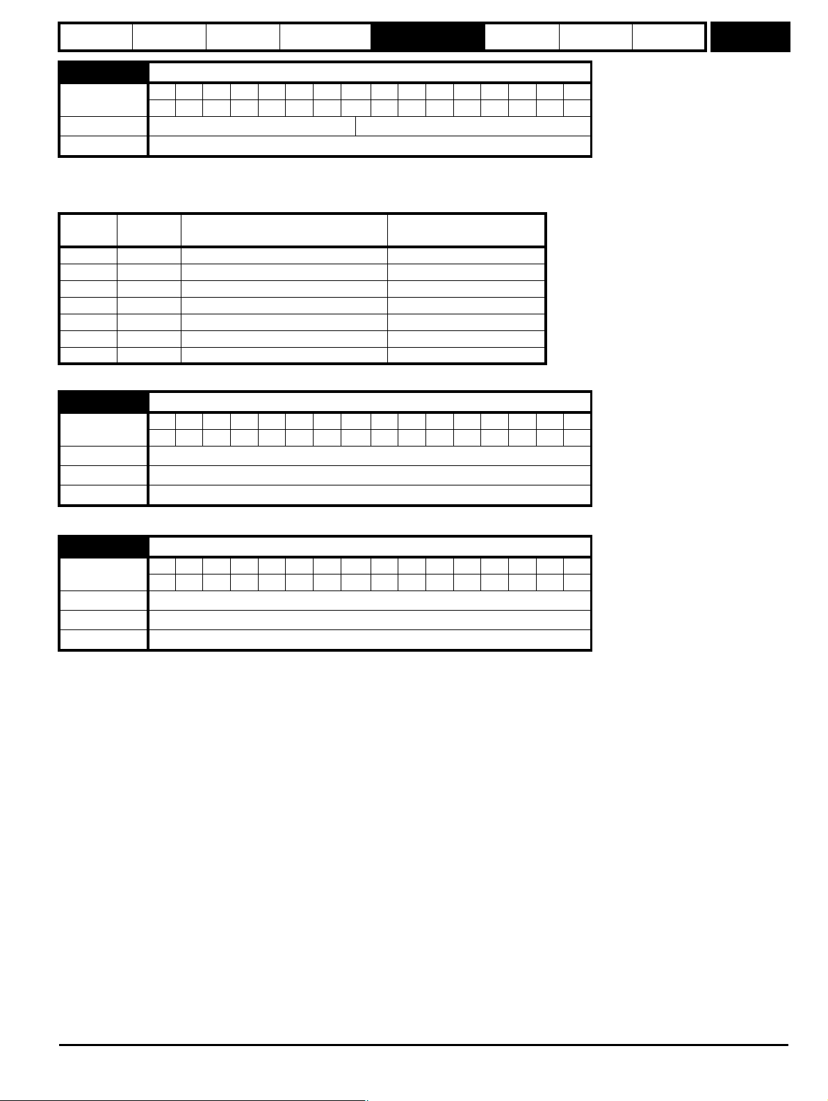
Parameter
structure
Keypad and
display
Parameter x.00
Parameter
description format
Advanced parameter
descriptions
Serial comms
protocol
Electronic
nameplate
Performance
Menu 5
5.37 Actual switching frequency
Coding
BitSP FI DETEVMDPNDRANCNVPTUSRWBUPS
11111
Range 0 to 7
Update rate
Background write
Pr 5.37 shows the actual switching frequency used by the inverter. The maximum switching frequency is set with parameter Pr 5.18, but this may be
reduced by the drive if automatic switching frequency changes are allowed (Pr 5.35=1). Pr 5.37 also indicates if the sample time for the current
controllers have been reduced to allow for SINCOS encoders with lines per revolution that are not a power of two.
Value String Switching frequency (kHz)
Current controller Sample
time (us)
03 3 167
14 4 125
26 6 83
38 8 125
412 12 83
66 rEd 6 167
7 12 rEd 12 167
5.38 Minimal movement phasing test angle
Coding
BitSP FI DETEVMDPNDRANCNVPTUSRWBUPS
1111
Range 0 to 25.5 degrees
Default 5.0 degrees
Update rate
Background read
5.39 Minimal movement phasing test pulse length
Coding
BitSP FI DETEVMDPNDRANCNVPTUSRWBUPS
111
Range 0 to 3
Default 0
Update rate
Background read
By applying short current pulses to the motor and using the resulting movement the drive can calculate the phasing angle (Pr 3.25 or Pr 21.20). These
begin at as short low level pulses, which are increased in magnitude and length until the required electrical movement define by Pr 5.38 is achieved.
The actual movement may be larger because motor cogging may cause additional unwanted movement. The required movement should only be
reduced if this is necessary as the results become less accurate with less movement. Care should be taken to ensure that the minimum movement is
large enough so that the change of position given by the feedback device can be registered by the drive. For example a 4096 line incremental device
on a 6 pole motor will give a change of position count of 75 for a 5° electrical movement. It is suggested that this test should not be used with a
change of position count of less than 50. Although Pr 5.38 can be reduced to zero the lowest value used by the drive is 1.0 degrees.
The necessary movement can be produced with a lower torque level if the test pulses are extended. If the pulses of torque are smaller then the
acceleration is less, and so the noise and vibration produced by the test are less. The pulse length can be modified with Pr 5.39 (1 = pulse lengths x
2, 2 = x 3, and 3 = x 4). Longer pulses should only be used if noise and vibration are a problem and the motor has low friction and low cogging torque.
As the torque level is reduced the measurement is likely to be affected by cogging and the results may not be accurate.
Digitax ST Advanced User Guide 87
Issue Number: 3
Page 88
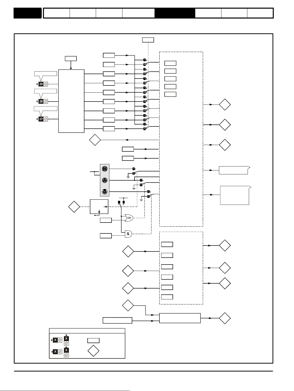
Menu 6
6.15
6.30
6.31
6.32
6.33
6.42
6.34
6.37
Logic
1
6.12
Keypad STOP
key
enable
6.13
Keypad
FWD/REV
key enable
1.11
Reference
enabled
indicator
1.12
Reverse
selected
indicator
1.13
Jog
selected
indicator
RUN
STOP/
RESET
FWD/REV
RESET
1.49
Reference
selected
indicator
Logic 1
6.17
Power
consumption
meter reset
6.18
Time
interval
between
filter changes
6.19
Filter
change
required/done
6.28
Select clock for trip
log time stamp
6.16
Electricity cost
per kWh
Clock control
6.24
6.25
Power
meter
6.26
Running
cost
6.27
Time
before
filter
change due
Inverter enable
Menu 2
Menu 3
Ramp
Hard speed
reference
enable
enable
6.20
6.21
Power-up
time
6.22
6.23
Run-time
5.03
To t a l m o t o r
power
0.XX
0.XX
Key
Read-write
(RW)
parameter
Read-only (RO)
parameter
Input
terminals
Output
terminals
The parameters are all shown at their default settings
Pr = 4?
1.49
6.43
01
Jog reverse
Run
Forward / Reverse
Run reverse
Jog forward
Run forward
Drive enable
Control word
Control word
enable
6.35
6.36
Limit switch 2
Limit switch 1
6.29
Hardware
enable
Menu 8
6.04
Stop / Start
***select
Sequencer
6.01
6.03
6.08
6.09
6.40
Stop mode
selector
Mains loss
mode**
Hold zero
speed *enable
Catch a
spinning motor
Enable sequencer
latching***
5.05
DC link voltage
Low voltage supply
Drive power supply monitor
6.44
Active supply
T25 digital I/O 2
T26 digital I/O 3
T27 digital input 4
6.39
Not stop
*
*
*
Keypad Plus
only
Yes
No
6.49
Disable multi module
drive module number
storing
Parameter
structure
Keypad and
display
Parameter x.00
5.8 Menu 6: Sequencer and clock
Figure 5-6 Menu 6 logic diagram
Parameter
description format
Advanced parameter
descriptions
Serial comms
protocol
Electronic
nameplate
Performance
88 Digitax ST Advanced User Guide
Issue Number: 3
Page 89

Parameter
structure
Keypad and
display
Parameter x.00
Parameter
description format
Advanced parameter
descriptions
Serial comms
protocol
Electronic
nameplate
Performance
Menu 6
6.01 Stop mode
Coding
Bit SP FI DE TE VM DP ND RA NC NV PT US RW BU PS
1 111
Range 0 to 2
Default 2
Update rate Background read
Only one stopping phase exists and the ready state is entered as soon as the single stopping action is complete. It should be noted that the stop
condition is detected when the speed feedback is below the zero speed threshold (Pr 3.05) for at least 16ms. If the speed is not stable it is possible
that the stop condition is not detected. In this case the system should be made more stable or the zero speed threshold should be raised.
Stopping Mode Action
0: Coast Inhibits the inverter
1: Ramp Stop with ramp
2: No ramp Stop with no ramp
If coast stop is selected the inverter is inhibited immediately when the run command is removed. If however, hold zero speed is also selected (Pr 6.08
= 1), then the inverter will be re-enabled to hold zero speed. The result is that the inverter is disabled for one sample and then enabled to ramp the
motor to a stop. Therefore if coast stop is required Pr 6.08 should be set to zero to disable hold zero speed.
If stop with ramp is selected the relevant ramp rate is used to stop the motor even if Pr 2.02 is set to zero to disable ramps.
The motor can be stopped with position orientation after stopping. This mode is selected with the position controller mode (Pr 13.10). When this mode
is selected Pr 6.01 has no effect.
6.03 Mains loss mode
Coding
Bit SP FI DE TE VM DP ND RA NC NV PT US RW BU PS
1111
Range 0 to 2
Default 0
Update rate Background read
0: dis
There is no mains loss detection and the drive operates normally only as long as the DC bus voltage remains within specification (i.e. >Vuv). Once the
voltage falls below Vuv a UV trip occurs and this will reset itself if the voltage rises again above Vuv Restart shown in the table below.
1: Stop
The speed reference is set to zero and the ramps are disabled allowing the drive to decelerate the motor to a stop under current limit. If the mains is
re-applied while the motor is stopping any run signal is ignored until the motor has stopped. If the current limit value is set at a very low level the drive
may trip UV before the motor has stopped. If the mains is reapplied the drive restarts after it reaches the ready state provided the necessary controls
are still active to initiate a start.
2: ride.th
The drive detects mains loss when the DC bus voltage falls below Vml
the DC bus level at Vml
bus voltage above the detection threshold Vml
. This causes the motor to decelerate at a rate that increases as the speed falls. If the mains is re-applied it will force the DC
2
and the drive will continue to operate normally. The output of the mains loss controller is a current
3
. The drive then enters a mode where a closed-loop controller attempts to hold
1
demand that is fed into the current control system and therefore the gain parameters Pr 4.13 and Pr 4.14 must be set up for optimum control. See
Pr 4.13 and Pr 4.14 on page 74 for set-up details.
The following table shows the voltage levels used by drives with each voltage rating.
Voltage level 200V drive 400V drive 575V drive 690V drive
Vuv 175 330 435 435
Vml
Vml
Vml
1
2
3
205* 410* 540* 540*
Vml1 - 10 V Vml1 - 20 V Vml1 - 25 V Vml1 - 25 V
Vml1 + 10 Vml1 + 15 Vml1 + 50 Vml1 + 50
Vuv Restart 215 425 590 590
is defined by Pr 6.48. The values given in the table are the default values.
* Vml
1
Digitax ST Advanced User Guide 89
Issue Number: 3
Page 90

Menu 6
Parameter
structure
Keypad and
display
Parameter x.00
Parameter
description format
Advanced parameter
descriptions
Serial comms
protocol
Electronic
nameplate
Performance
6.04 Start/stop logic select
Coding
BitSP FI DETEVMDPNDRANCNVPTUSRWBUPS
111
Range 0 to 4
Default 4
Update rate Background read
This parameter is provided to allow the user to select several predefined digital input routing macros to control the sequencer. When a value between
0 and 3 is selected the drive processor continuously updates the destination parameters for digital I/O T25, T26 and T27, and the enable sequencer
latching bit (Pr 6.40). When a value of 4 is selected the destination parameters for these digital I/O and Pr 6.40 can be modified by the user. (Note any
changes made to the destination parameters only become active after a drive reset).
Pr 6.04 T25 (Pr 8.22) T26 (Pr 8.23) T27 (Pr 8.24) Pr 6.40
0Pr 6.29* Pr 6.30 Run Forward Pr 6.32 Run Reverse 0 (non latching)
1Pr 6.39 Not stop Pr 6.30 Run Forward Pr 6.32 Run Reverse 1 (latching)
2Pr 6.29* Pr 6.34 Run Pr 6.33 Fwd /Rev 0 (non latching)
3Pr 6.39 Not stop Pr 6.34 Run Pr 6.33 Fwd/Rev 1 (latching)
4 User prog User prog User prog User prog
*Pr 6.29 reflects the state of the Safe Torque Off input and so it is not necessary to control this with a digital input, but the set up here is provided for
compatibility with older products. Routing a digital input can be used for fast disabling, see Pr 6.29 for more details.
6.08 Hold zero speed
Coding
Bit SP FI DE TE VM DP ND RA NC NV PT US RW BU PS
111
Default 1
Update rate 4 ms read
When this bit is set the drive remains active even when the run command has been removed and the motor has reached standstill. The drive goes to
the 'StoP' state instead of the 'rdy' state.
6.09 Catch a spinning motor
Coding
BitSP FI DETEVMDPNDRANCNVPTUSRWBUPS
111
Range 1
Default 1
Update rate Background read
When the drive is enabled with this bit at zero, the post ramp reference (Pr 2.01) starts at zero and ramps to the required reference. When the drive is
enabled with this parameter at one, the post ramp reference is set to the motor speed.
6.12 Enable stop key
Coding
BitSP FI DETEVMDPNDRANCNVPTUSRWBUPS
111
Default 0
Update rate Background read
This parameter permanently enables the Stop key on the drive such that the drive will always stop when the Stop key is pressed. If keypad mode is
selected this has no effect because the Stop key is automatically enabled.
The sequencer logic has been designed so that pressing the Stop key, whether the Stop key is enabled or not, does not make the drive change from
a stopped to a running condition. As the Stop key is also used to reset trips this means that if the Stop key is pressed when the drive is tripped, the trip
will be reset, but the drive does not start. (This does not apply to the UV trip which cannot be reset by the user, but is automatically reset when the DC
bus voltage is high enough.) Preventing the drive from starting when the stop key is pressed is implemented as follows.
Sequencer latching not enabled (Pr 6.40=0)
If the Stop key is pressed when the Stop key is enabled (Pr 6.12=1) or when the drive is tripped the sequencer run is removed, and so the drive stops
or remains stopped respectively. The sequencer run can only then be reapplied after at least one of the following conditions occurs.
1. Run forward, Run reverse and Run sequencing bits all zero
2. OR the drive is disabled via Pr 6.15 or Pr 6.29
3. OR Run forward and Run reverse are both active and have been for 60ms.
4. The drive is in the UV state.
90 Digitax ST Advanced User Guide
Issue Number: 3
Page 91

Parameter
structure
Keypad and
display
Parameter x.00
Parameter
description format
Advanced parameter
descriptions
Serial comms
protocol
Electronic
nameplate
Performance
Menu 6
The drive can then be restarted by activating the necessary bits to give a normal start.
Sequencer latching enabled (Pr 6.40=1)
If the Stop key is pressed when the stop key is enabled (Pr 6.12=1) or when the drive is tripped the sequencer run is removed, and so the drive stops
or remains stopped respectively. The sequencer run can only then be reapplied after at least one of the following conditions occurs.
1. Run forward, Run reverse and Run sequencing bits all zero after the latches
2. OR Not stop sequencing bit is zero
3. OR the drive is disabled via Pr 6.15 or Pr 6.29
4. OR Run forward and Run reverse are both active and have been for 60ms.
5. The drive is in the UV state.
The drive can then be restarted by activating the necessary bits to give a normal start. Note that Run forward and Run reverse together will reset the
stop key condition, but the latches associated with Run forward and Run reverse must then be reset before the drive can be restarted. It should be
noted holding the Run key and pressing the Stop key to reset the drive without stopping does not apply unless keypad reference mode is selected.
6.13 Enable forward/reverse key
Coding
Bit SP FI DE TE VM DP ND RA NC NV PT US RW BU PS
111
Default 0
Update rate Background read
6.15 Drive enable
Coding
Bit SP FI DE TE VM DP ND RA NC NV PT US RW BU PS
1111
Default 1
Update rate 4ms read
Setting this parameter to 0 will disable the drive. It must be at 1 for the drive to run.
6.16 Electricity cost per kWh
Coding
BitSP FI DETEVMDPNDRANCNVPTUSRWBUPS
1 111
Range 0.0 to 600.0 currency units per kWh
Default 0
Update rate Background read
When this parameter is set up correctly for the local currency, Pr 6.26 will give an instantaneous read out of running cost.
6.17 Reset energy meter
Coding
BitSPFIDETEVMDPNDRANCNVPTUSRWBUPS
111
Default 0
Update rate Background read
If this parameter is one the energy meter (Pr 6.24 and Pr 6.25) is reset and held at zero.
6.18 Time between filter changes
Coding
Range
Default
Update rate
Bit SP FI DE TE VM DP ND RA NC NV PT US RW BU PS
1111
0 to 30,000 hrs
0
Background read
Digitax ST Advanced User Guide 91
Issue Number: 3
Page 92

Menu 6
Parameter
structure
Keypad and
display
Parameter x.00
Parameter
description format
Advanced parameter
descriptions
Serial comms
protocol
Electronic
nameplate
Performance
6.19 Filter change required / change done
Coding
Bit SP FI DE TE VM DP ND RA NC NV PT US RW BU PS
111
Default 0
Update rate Background read/write
To enable the feature that indicates to the user when a filter change is due Pr 6.18 should be set to the time between filter changes. When the drive is
running, Pr 6.27 is reduced each time the runtime timer hour increments (Pr 6.23) until Pr 6.27 reaches 0, at which point Pr 6.19 is set to 1 to inform
the user that a filter change is required. When the user has changed the filter, resetting Pr 6.19 to 0 will indicate to the drive that the change has been
done and Pr 6.27 will be reloaded with the value of Pr 6.18. Pr 6.27 can be updated with the value of Pr 6.18 at any time by setting and clearing this
parameter manually. If Pr 6.18=0, then Pr 6.27 is held at zero and so parameters should be saved after Pr 6.18 has been setup so that this system will
function correctly after the drive is powered down and powered up again.
6.20 Powered-up time: years.days
Coding
Bit SP FI DE TE VM DP ND RA NC NV PT US RW BU PS
31 1 1 11
Range 0 to 9.364 Years.Days
Update rate Background write
6.21 Powered-up time: hours.minutes
Coding
BitSP FI DETEVMDPNDRANCNVPTUSRWBUPS
21 1 1 11
Range 0 to 23.59 Hours.Minutes
Update rate Background write
The powered-up clock always starts at zero each time the drive is powered-up. The time can be changed by the user from the keypad, serial comms
or an application module. If the data is not written with the various parts in the correct range (i.e. minutes are greater than 59, etc.) the clock is set to
zero on the next minute. This clock may be used for time stamping the trip log if Pr 6.28 = 0.
6.22 Run time: years.days
Coding
BitSP FI DETEVMDPNDRANCNVPTUSRWBUPS
31 1 1 11
Range 0 to 9.364 Years.Days
Update rate Background write
6.23 Run time: hours.minutes
Coding
BitSP FI DETEVMDPNDRANCNVPTUSRWBUPS
21 1 1 11
Range 0 to 23.59 Hours.Minutes
Update rate Background write
The run time clock increments when the drive inverter is active to indicate the number of minutes that the drive has been running since leaving the
Control Techniques factory. This clock may be used for time stamping the trip log if Pr 6.28 = 1.
6.24 Energy meter: MWh
Coding
BitSP FI DETEVMDPNDRANCNVPTUSRWBUPS
11 1 1 1
Range ±999.9 MWh
Update rate Background write
92 Digitax ST Advanced User Guide
Issue Number: 3
Page 93

Parameter
structure
Keypad and
display
Parameter x.00
Parameter
description format
Advanced parameter
descriptions
Serial comms
protocol
Electronic
nameplate
Performance
Menu 6
6.25 Energy meter: kWh
Coding
Bit SP FI DE TE VM DP ND RA NC NV PT US RW BU PS
21 1 1 1
Range ±99.99 kWh
Update rate Background write
Pr 6.24 and Pr 6.25 form the energy meter that indicates the net energy supplied to/from the drive in kWh. (i.e. energy supplied by the drive - energy
fed back to the drive). For motor control modes a positive value indicates the net transfer of energy from the drive to the motor. If the maximum or
minimum of Pr 6.24 is reached, the parameter does not roll over but is instead clamped to the maximum or minimum value.
6.26 Running cost
Coding
BitSP FI DETEVMDPNDRANCNVPTUSRWBUPS
1111
Range ±32,000
Update rate Background write
Instantaneous read out of the cost/hour of running the drive. This requires Pr 6.16 to be set up correctly.
6.27 Time before filter change due
Coding
BitSP FI DETEVMDPNDRANCNVPTUSRWBUPS
111 11
Range 0 to 30,000 hrs
Update rate Background read
See Pr 6.18 on page 91.
6.28 Select clock for trip log time stamping
Coding
Bit SP FI DE TE VM DP ND RA NC NV PT US RW BU PS
111
Default 0
Update rate Background read
The trip log includes time stamping for individual trips provided Pr 6.49 is set to one. If Pr 6.28 is zero, the powered-up clock is used for time
stamping. If Pr 6.28 is one, the run time clock is used for time stamping. It should be noted that changing this parameter clears the trip and trip time
logs.
6.29 Hardware enable
Coding
BitSP FI DE TEVMDPNDRANCNVPTUSRWBU PS
111
Update rate 4ms write
This bit shows whether the drive is in the enable state or not.
Generally this will reflect the state of the enable input and shows the same value as Pr 8.09. However the disabled state can be forced by other
functions within the drive. Pr 8.09 will always follow the enable input state but the Pr 6.29 will be held at zero, indicating that the drive is forced into the
disable state by the following:
1. A digital input is routed to this parameter as described below to provide a fast disable and the input forces this parameter to zero.
2. Any of the following trips are active: OI.AC, PS.10V, PS.24V, OI.Br, OV.
If the destination of one of the drive digital I/O (Pr 8.21 to Pr 8.26) is set to Pr 6.29 and the I/O is set as an input, it provides a fast disable function. The
Safe Torque Off input to the drive (T31) disables the drive in hardware by removing the gate drive signals from the inverter IGBT's and also disables
the drive via the software system. When the drive is disabled by de-activating the Safe Torque Off input there can be a delay of up to 20 ms. However,
if a digital I/O is set up to provide the fast disable function it is possible to disable the drive within 600 us of de-activating the input. To do this the
enable signal should be connected to both the Safe Torque Off (T31) and to the digital I/O selected for the fast disable function. The state of the digital
I/O including the effect of its associated invert parameter is ANDed with the Safe Torque Off to enable the drive.
If the safety function of the Safe Torque Off input is required then there must not be a direct connection between the Safe Torque Off input (T31) and
any other digital I/O on the drive. If the safety function of the Safe Torque Off input and the fast disable function is required then the drive should be
given two separate independent enable signals. A safety related enable from a safe source connected to the Safe Torque Off input on the drive.
Digitax ST Advanced User Guide 93
Issue Number: 3
Page 94
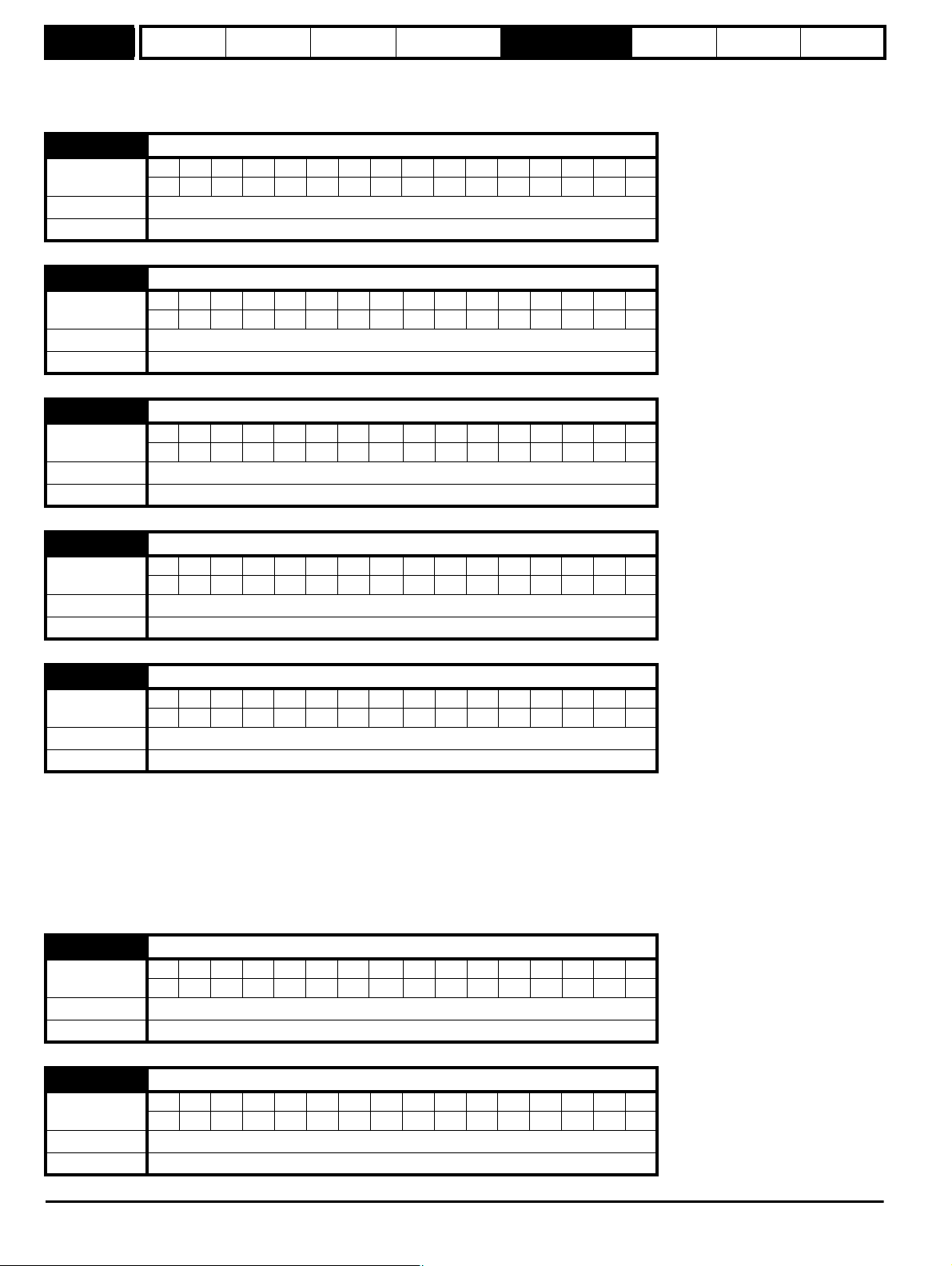
Menu 6
Parameter
structure
Keypad and
display
Parameter x.00
Parameter
description format
Advanced parameter
descriptions
Serial comms
protocol
Electronic
nameplate
Performance
A second enable connected to the digital I/O on the drive selected for the fast disable function. The circuit must be arranged so that a fault which
causes the fast input to be forced high cannot cause the Safe Torque Off input to be forced high, including the case where a component such as a
blocking diode has failed.
6.30 Sequencing bit: Run forward
Coding
BitSP FI DETEVMDPNDRANCNVPTUSRWBUPS
111
Default 0
Update rate 4ms read
6.31 Sequencing bit: Jog
Coding
BitSP FI DETEVMDPNDRANCNVPTUSRWBUPS
111
Default 0
Update rate 4ms read
6.32 Sequencing bit: Run reverse
Coding
Bit SP FI DE TE VM DP ND RA NC NV PT US RW BU PS
111
Default 0
Update rate 4ms read
6.33 Sequencing bit: Forward/reverse
Coding
BitSP FI DETEVMDPNDRANCNVPTUSRWBUPS
111
Default 0
Update rate 4ms read
6.34 Sequencing bit: Run
Coding
Bit SP FI DE TE VM DP ND RA NC NV PT US RW BU PS
111
Default 0
Update rate 4ms read
In normal operation the sequencer has been designed to operate with Run forward / Run reverse controls, or with a Run control and a forward
reverse selector. If Run forward / Run reverse control is required then bits Pr 6.30 and Pr 6.32 should be used to control the drive (digital inputs should
not be routed to bits Pr 6.33 and Pr 6.34). If Run control with a forward reverse selector is required then bits Pr 6.33 and Pr 6.34 should be used to
control the drive (digital inputs should not be routed to bits Pr 6.30 and Pr 6.32).
The Run forward and Run reverse, or Run sequencing bits can be made latching by setting bit Pr 6.40. The Not stop bit (Pr 6.39) should be one to
allow the sequencing bit to be latched. If the Not stop bit is zero all latches are cleared and held at zero. The jog or jog reverse sequencing bits can
also cause the drive to run provided the motor is stopped when these bits are activated and the normal run sequencing bits are not providing a run
signal.
6.35 Forward limit switch
Coding
Bit SP FI DE TE VM DP ND RA NC NV PT US RW BU PS
111
Default 0
Update rate 250 μs read
6.36 Reverse limit switch
Coding
Bit SP FI DE TE VM DP ND RA NC NV PT US RW BU PS
111
Default 0
Update rate 250 μs read
94 Digitax ST Advanced User Guide
Issue Number: 3
Page 95

Parameter
structure
Keypad and
display
Parameter x.00
Parameter
description format
Advanced parameter
descriptions
Serial comms
protocol
Electronic
nameplate
Performance
Menu 6
Digital inputs connected to limit switches should be routed to these parameters if fast stopping is required at a limit. The drive will respond in 750 μs
(500 μs digital input filter delay + 250 μs software delay) and stop the motor with zero ramp rate (i.e. in current limit). The limit switches are direction
dependant so that the motor can rotate in a direction that allows the system to move away from the limit switch.
Pre-ramp reference+hard speed reference > 0 rpm Forward limit switch active
Pre-ramp reference+hard speed reference < 0 rpm Reverse limit switch active
Pre-ramp reference+hard speed reference = 0 rpm Both limit switches active
6.37 Sequencing bit: Jog reverse
Coding
Bit SP FI DE TE VM DP ND RA NC NV PT US RW BU PS
111
Default 0
Update rate 4 ms read
6.39 Sequencing bit: Not stop
Coding
Bit SP FI DE TE VM DP ND RA NC NV PT US RW BU PS
111
Default 0
Update rate 4 ms read
6.40 Enable sequencer latching
Coding
BitSP FI DETEVMDPNDRANCNVPTUSRWBUPS
111
Default 0
Update rate 4 ms read
6.41 Drive event flags
Coding
BitSP FI DETEVMDPNDRANCNVPTUSRWBUPS
111
Range 0 to 65535
Default 0
Update rate Background write
The drive event flags indicate certain actions have occurred within the drive as described below.
Defaults loaded (Bit 0)
The drive sets bit 0 when defaults have been loaded and the associated parameter save has been completed. The drive does not reset this flag
except at power-up. This flag is intended to be used by SM-Applications Solutions Module programs to determine when the default loading process is
complete. For example an application may require defaults that are different from the standard drive defaults. These may be loaded and another
parameter save initiated by the SM-Applications module when this flag is set. The flag should then be cleared so that the next event can be detected.
6.42 Control word
Coding
BitSP FI DETEVMDPNDRANCNVPTUSRWBUPS
111
Range 0 to 32,767
Default 0
Update rate Bits 0 –7: 4 ms read, Bits 8-15: Background read
6.43 Control word enable
Coding
BitSP FI DETEVMDPNDRANCNVPTUSRWBUPS
111
Default 0
Update rate Related to bits 0-7: 4 ms read, related to bits 8-15: Background read
Pr 6.42 and Pr 6.43 provide a method of controlling the sequencer inputs and other functions directly from a single control word. If Pr 6.43 = 0 the
control word has no effect, if Pr 6.43 = 1 the control word is enabled. Each bit of the control word corresponds to a sequencing bit or function as
shown below.
Digitax ST Advanced User Guide 95
Issue Number: 3
Page 96

Menu 6
Parameter
structure
Keypad and
display
Parameter x.00
Parameter
description format
Advanced parameter
descriptions
Serial comms
protocol
Electronic
nameplate
Performance
Bit Function Equivalent parameter
0 Drive enable Pr 6.15
1 Run forward Pr 6.30
2Jog Pr 6.31
3 Run reverse Pr 6.32
4 Forward/reverse Pr 6.33
5Run Pr 6.34
6Not stop Pr 6.39
7 Auto/manual
8 Analog/Preset reference Pr 1.42
9 Jog reverse Pr 6.37
10 Reserved
11 Reser ved
12 Trip drive
13 Reset drive Pr 10.33
14 Keypad watchdog
Bits 0-7 and bit 9: sequencing control
When the control word is enabled (Pr 6.43 = 1), and the Auto/manual bit (bit7) are both one, bits 0 to 6 and bit 9 of the control word become active.
The equivalent parameters are not modified by these bits, but become inactive when the equivalent bits in the control word are active. When the bits
are active they replace the functions of the equivalent parameters. For example, if Pr 6.43 = 1 and bit 7 of Pr 6.42 = 1 the drive enable is no longer
controlled by Pr 6.15, but by bit 0 of the control word. If either Pr 6.43 = 0, or bit 7 of Pr 6.42 = 0, the drive enable is controlled by Pr 6.15.
Bit 8: Analog/preset reference
When the control word is enabled (Pr 6.43) bit 8 of the control word becomes active. (Bit 7 of the control word has no effect on this function.) The state
of bit 8 is written to Pr 1.42. With default drive settings this selects analog reference 1 (bit8 = 0) or preset reference 1 (bit8 = 1). If any other drive
parameters are routed to Pr 1.42 the value of Pr 1.42 is undefined.
Bit 12: Trip drive
When the control word is enabled (Pr 6.43) bit 12 of the control word becomes active. (Bit 7 of the control word has no effect on this function.) When
bit 12 is set to one a CL.bit trip is initiated. The trip cannot be cleared until the bit is set to zero
Bit 13: Reset drive
When the control word is enabled (Pr 6.43) bit 13 of the control word becomes active. (Bit 7 of the control word has no effect on this function.) When
bit 13 is changed from 0 to 1 the drive is reset. This bit does not modify the equivalent parameter (Pr 10.33).
Bit 14: Keypad watchdog
When the control word is enabled (Pr 6.43) bit 14 of the control word becomes active. (Bit 7 of the control word has no effect on this function.) A
watchdog is provided for an external keypad or other device where a break in the communication link must be detected. The watchdog system can be
enabled and/or serviced if bit 14 of the control word is changed from zero to one with the control word enabled. Once the watchdog is enabled it must
be serviced at least once every second or an "SCL" trip occurs. The watchdog is disabled when an "SCL" trip occurs, and so it must be re-enabled
when the trip is reset. It should be noted that when data is transferred from a SMARTCARD to the drive there may be a delay of up to 1.5 s for the
comms to respond. Once the comms starts to respond again normally the watchdog will not time out for a further 2 s even if it is not serviced. This
period is allowed for the system connected to the comms port to recover if required and to begin servicing the watchdog again.
6.44 Active supply
Coding
Bit SP FI DETEVMDPNDRANCNVPTUSRWBUPS
1 111
Update rate Background write
The drive can operate from either a high voltage supply or a low voltage DC supply, usually from a battery. Different methods are used to connect the
low voltage battery supply depending on the frame size of the drive. This parameter, which indicates which supply is active, is set up to the correct
value just as the UV trip is reset. A low voltage DC supply should not be used without first consulting the appropriate documentation on the power and
control connections required for this mode.
0: Normal high voltage supply
The drive is operating in normal high voltage supply mode.
The drive is using the main power terminals to derive its control supplies. The drive will operate normally. Parameters that are saved at power-down
are saved when the supply is removed and a UV trip occurs.
1: Low voltage battery supply
The drive is operating in low voltage DC mode.
The drive is using the low voltage auxiliary power input to derive the power circuit supplies (i.e. gate drives, fans, etc.). The main power terminals can
be connected to a different supply of any voltage up to the maximum normal supply level. All parameters voltage based parameters are calculated
from the auxiliary supply level and not the supply from the main power terminals. If the auxiliary supply and the main supply a
re different then these
parameters will not be correct. Parameters that are saved at power-down are not saved when the power is removed in this mode.
24V must also be supplied via the 24V control board power supply input. The drive will operate normally except that mains loss detection is disabled,
the braking IGBT will only operate when the drive is enabled, and the voltage levels contained in the following table are used instead of the normal
high voltage levels whatever the voltage rating of the drive.
96 Digitax ST Advanced User Guide
Issue Number: 3
Page 97

Parameter
structure
Keypad and
display
Parameter x.00
Parameter
description format
Advanced parameter
descriptions
Serial comms
protocol
Electronic
nameplate
Performance
Menu 6
Voltage level
DC_VOLTAGE_MAX Pr 6.46 x 1.45
Braking IGBT threshold voltage Pr 6.46 x 1.325
Under voltage trip level 36 V
Restart voltage level after UV trip 40 V
Full scale voltage measurement and the over voltage trip level are defined by DC_VOLTAGE_MAX. However, the maximum level of the low voltage
DC should not normally exceed 90 % of this value to avoid spurious over voltage trips.
6.45 Force cooling fan to run at full speed
Coding
Bit SP FI DETEVMDPNDRANCNVPTUSRWBUPS
111
Update rate Background read
The drive thermal model system normally controls the fan speed, however the fan can be forced to operate at full speed if this parameter is set to 1.
When this is set to 1 the fan remains at full speed until 10 s after this parameter is set to zero.
When the drive is in the UV state the fan always runs at minimum.
6.46 Nominal low voltage DC supply
Coding
Bit SP FI DE TE VM DP ND RA NC NV PT US RW BU PS
1111
Range 48 to 72 V
Default 48
Update rate Background read
This parameter defines the nominal supply voltage when operating in low voltage mode. The parameter is used to define the braking IGBT switching
threshold and the over voltage trip level for low voltage battery mode (see Pr 6.44).
6.47 Disable mains/phase loss detection from input rectifier
Coding
Bit SP FI DE TE VM DP ND RA NC NV PT US RW BU PS
111
Default 0
Update rate Background read
Digitax ST has a diode rectifier input stage with no direct monitoring system. Mains loss and phase loss detection is derived from the DC bus voltage.
This parameter has no effect.
6.48 Mains loss ride through detection level
Coding
Bit SP FI DE TE VM DP ND RA NC NV PT US RW BU PS
1 1 111
Range 0 to DC_VOLTAGE_SET_MAX V
Default
200V rated drive 205
400V rated drive 410
Update rate Background read
The mains loss detection level can be adjusted using this parameter. If the value is reduced below the default value the default value is used by the
drive. If the level is set too high so that mains loss detection becomes active under normal operating conditions the motor will coast to a stop.
6.49 Disable multi-module drive module number storing on trip
Coding
Bit SP FI DE TE VM DP ND RA NC NV PT US RW BU PS
111
Default 0
Update rate Background read
If Pr 6.49 is zero the module number is stored in the module number and trip time log. If this parameter is one, either the powered-up clock or run time
clock is stored in the module number and trip time log as defined by Pr 6.28. It should be noted that changing this parameter clears the trip, and
module number and trip time logs.
Digitax ST Advanced User Guide 97
Issue Number: 3
Page 98

Menu 6
Parameter
structure
Keypad and
display
Parameter x.00
Parameter
description format
Advanced parameter
descriptions
Serial comms
protocol
Electronic
nameplate
Performance
6.50 Drive comms state
Coding
Bit SP FI DE TE VM DP ND RANCNVPTUSRWBUPS
11111
Default 0 to 3
Update rate Background write
The drive comms system 128 bytes buffer used with ANSI or Modbus rtu protocols via the 485 connector can be controlled by a Solutions Module
under certain circumstances. This parameter shows which node has control of the buffer (0 (drv) = drive, 1 (Slot1) = Solutions Module in slot 1, etc. If
a Solutions Module has control of the buffer the drive will use an alternative buffer for 485 comms and the following restrictions will apply:
1. Comms messages via the 485 port are limited to a maximum of 32 bytes
2. The 6 pin keypad port will operate correctly with an LED keypad, but it will no longer operate with an LCD keypad
3. Modbus messages using the CMP protocol can only route messages to nodes within the drive. It will not be possible for these to be routed further,
i.e. via CT Net on an SM Applications module.
6.51 External rectifier not active
Coding
Bit SP FI DE TE VM DP ND RANCNVPTUSRWBUPS
1 1
Default 0
Update rate 1ms read
When a drive with an internal rectifier is used this parameter should be left at zero. For a drive with an active external rectifier (used to control DC bus
charging) this parameter should be the destination of the output of a variable selector set up for external rectifier monitoring. This allows the
monitoring block to prevent the drive from leaving the main loss ride through mode until the rectifier is fully active and phased forwards. If this feature
is not used the mains loss ride through mode ends as soon as the DC Bus voltage is above the mains loss detection level. The rectifier may still be
phasing forwards and the application of load at this point may cause the DC Bus voltage to fall back below the mains loss detection level again.
98 Digitax ST Advanced User Guide
Issue Number: 3
Page 99

Parameter
structure
Keypad and
display
Parameter x.00
Parameter
description format
Advanced parameter
descriptions
Serial comms
protocol
Electronic
nameplate
Performance
Menu 7
5.9 Menu 7: Analog I/O
Hardware
The drive has three analog inputs (AI1 to AI3) and two analog outputs (AO1 and AO2). Each input has a similar parameter structure and each output
has a similar parameter structure. The nominal full scale level for inputs in voltage mode is 9.8V. This ensures that when the input is driven from a
voltage produced from the drive's own 10V supply, the input can reach full scale.
Terminal Input Input modes Resolution
5/6 AI1 Voltage only
(16 bit plus sign as a speed reference)
7 AI2 0 to 6 10 bit plus sign
8 AI3 0 to 9 10 bit plus sign
Terminal Output Output modes Resolution
9 AO1 0 to 3 10 bit plus sign
10 AO2 0 to 3 10 bit plus sign
Update rate
The analog inputs are sampled every 4ms except where the destinations shown in the table below are chosen, the input is in voltage mode and other
conditions necessary for short cutting are met.
Input destination Sample rate
Pr 1.36 - Analog reference
Pr 1.37 - Analog reference
Pr 3.22 - Hard speed reference
Pr 4.08 - Torque reference
250 μs
(AI1 subject to window filter. See Pr 7.26 on page 105)
250 μs
(AI1 subject to window filter. See Pr 7.26 on page 105)
250 μs
(AI1 subject to window filter. See Pr 7.26 on page 105)
AI1 – 4 ms
AI2 or 3 – 250 μs
Analog outputs are updated every 4ms except when the source is Pr 3.02, Pr 4.02, Pr 4.17 and Pr 5.03 and high speed update mode is selected. In
high speed mode the output operates in voltage mode. It is updated every 250μs and special scaling is used as described in the table. User scaling is
ignored.
Output source Scaling
Pr 3.02 – speed 10.0 V = SPEED_MAX
Pr 4.02 - torque prod current
10.0 V = Kc / 0.45
where Kc is the current scaling factor for the drive
Pr 4.17 - magnetising current 10.0 V = Kc / 0.45
The output is the product of the active current and the voltage component in phase
with the active current (vsy x isy).
Pr 5.03 - output power
10 V would be produced when:
Active current = Kc / 0.45
Peak phase voltage in phase with the active current = DC_VOLTAGE_MAX / 2
12 bit plus sign
Digitax ST Advanced User Guide 99
Issue Number: 3
Page 100

Menu 7
Analog input 2
A/D
7.11
Analog input 2
mode selector
7.12
Analog
input 2
scaling
??.??
Any
unprotected
variable
parameter
??.??
7.14
7.25
Calibrate
analog input 1
full scale
7.26
V/f sample
time
7.07
Analog input
1 offset trim
7.08
Analog
input 1
scaling
??.??
Any
unprotected
variable
parameter
??.??
7.10
Analog input 1
destination
parameter
V/f
x(-1)
Analog input 1
Analog input 3
A/D
7.15
Analog input 3
mode selector
7.16
Analog
input 3
scaling
??.??
Any
unprotected
variable
parameter
??.??
7.18
??.??
Any variable
parameter
??.??
7.19
Analog output 1
source parameter
7.20
Analog
output 1
scaling
7.21
Analog
output 1
mode
selector
Analog output 1
??.??
Any
variable
parameter
??.??
7.22
Analog output 2
source parameter
7.23
Analog
output 2
scaling
7.24
Analog
output 2
mode
selector
7.09
Analog
input 1 invert
x(-1)
7.01
Analog
input 1
7.02
Analog
input 2
x(-1)
7.17
Analog
input 3 invert
7.13
Analog
input 2 invert
Analog output 2
5
6
7
8
1.36
Analog
ref. 1
1.37
Analog
ref. 2
9
10
3.02
Speed
feedback
4.02
Motor
active
current
0.XX
0.XX
Key
Read-write (RW)
parameter
Read-only (RO)
parameter
Input
terminals
Output
terminals
X
X
X
X
The parameters are all shown at their default settings
+
+
+
+
7.30
Analog input
1 offset
7.28
Analog input 2
current loop loss
+
+
7.31
+
+
7.31
Analog input
2 offset
+
+
7.31
+
+
7.32
Analog input
3 offset
7.29
Analog input 3
current loop loss
7.33
Analog
output 1 control
Analog input 2
destination
parameter
Analog input 3
destination
parameter
7.03
Analog
input 3
Parameter
structure
Figure 5-7 Menu 7 logic diagram
Keypad and
display
Parameter x.00
Parameter
description format
Advanced parameter
descriptions
Serial comms
protocol
Electronic
nameplate
Performance
7.01 T5/6 analog input 1 level
Bit SP FI DE Txt VM DP ND RA NC NV PT US RW BU PS
Coding
Range ±100.00 %
Update rate 4ms write
100 Digitax ST Advanced User Guide
21 1 1
Issue Number: 3
 Loading...