

Page 1
DIGITAX HD
SERVO DRIVE SERIES
Minimum size,
maximum performance
0.7 – 51 Nm, 300% overload
(6.2 – 451 lb-in, 300% overload)
1.5 – 16 A, 300% overload
200 V | 400 V
0.25 – 7.5 kW (0.6 - 9.8 hp)
Page 2
SERVO DRIVE SERIES
SERVO DRIVE SERIES
Servo solutions
for continuous
and pulse duty
applications
Control Techniques’ servo solutions provide
ultimate performance and fl exibility for
machinery manufacturers with a wide range of
servo drives and motors.
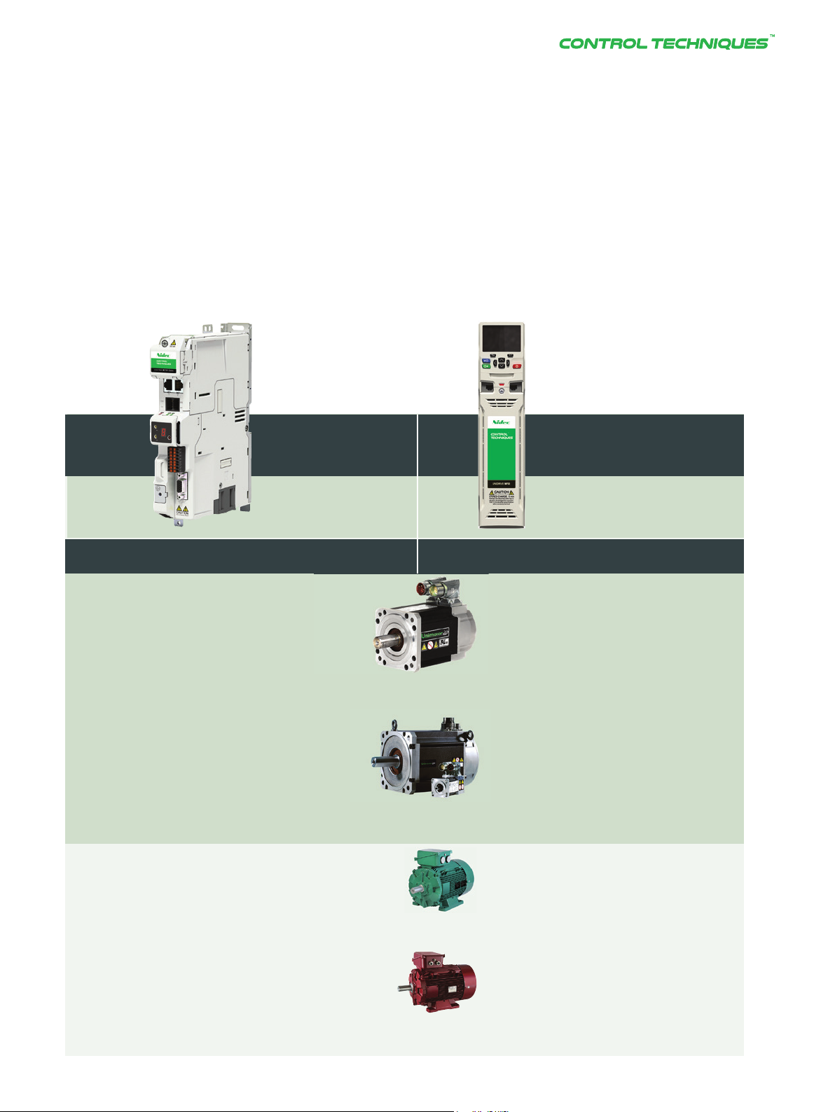
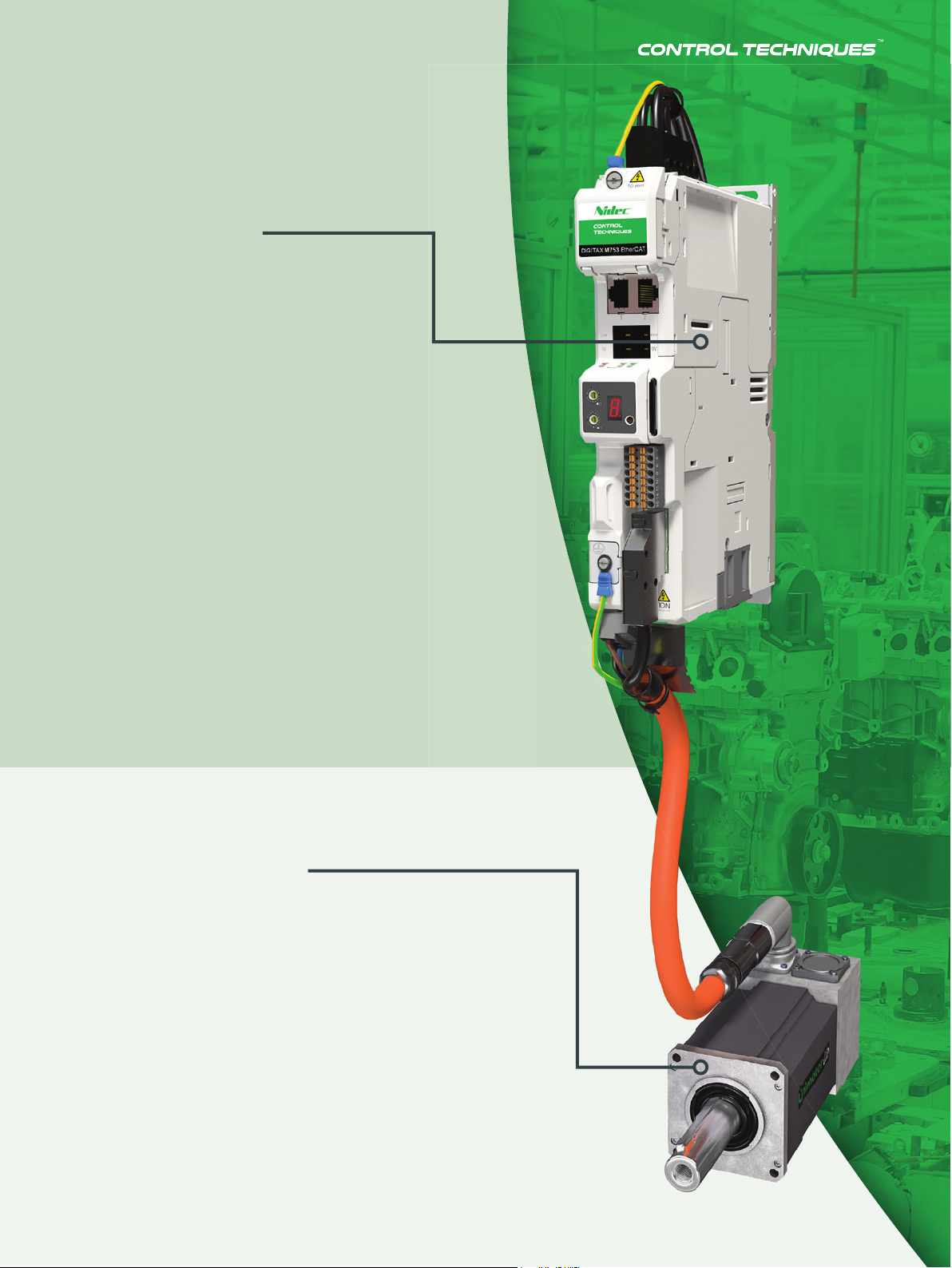
Digitax HD
The Digitax HD range brings ultimate
performance to high dynamic, pulse duty
applications, where high peak torque is
required for fast acceleration.
Unidrive M700
Unidrive M700, with high performance and an extensive
power range, is the ideal option for continuous duty
applications, where precise, continuous torque delivery is
required.
Unimotor
Unimotor is a comprehensive family of high performance AC
brushless servo motors. With a wide torque and speed range,
and a broad selection of feedback options, Unimotor off ers
the perfect match for Digitax HD and Unidrive M700 to meet
any application requirement.
2
2
Page 3
Drive and Motor
Compatibility
Digitax HD
0.25 kW - 7.5 kW
(0.6 hp - 9.8 hp)
200 V | 400 V
300% OVERLOAD
(Optimized with the Control Techniques pulse duty drive)
Unidrive M700
0.75 kW - 2.8 MW
(1 hp - 4,200 hp)
200 V | 400 V | 575 V | 690 V
200% OVERLOAD
Pulse Duty Servo Range - Unimotor HD
Continuous Duty Servo Range - Unimotor FM
(Optimized with the Control Techniques continuous duty drive)
Induction
High efficiency motors
DRIVE SPECIALISTS SINCE 1973
DRIVE SPECIALISTS SINCE 1973 3
3
Page 4
SERVO DRIVE SERIES SERVO DRIVE SERIES
4
4
Page 5
Digitax HD
Optimized for high-dynamic
applications, Digitax HD provides
the fl exibility of both standalone
and modular confi gurations. The
drive off ers full servo control plus
open loop permanent magnet and
induction motor control across
four functionality levels: EtherCAT,
MCi machine control, multiprotocol
EtherNet and the fl exible Base drive.
Unimotor HD
Unimotor HD is Control Techniques’ highly
dynamic brushless AC servo motor range.
With high peak torque, low inertia and
compact dimensions, Unimotor HD is
optimized for applications requiring rapid
acceleration and deceleration.
DRIVE SPECIALISTS SINCE 1973
DRIVE SPECIALISTS SINCE 1973 5
5
Page 6
SERVO DRIVE SERIES
SERVO DRIVE SERIES
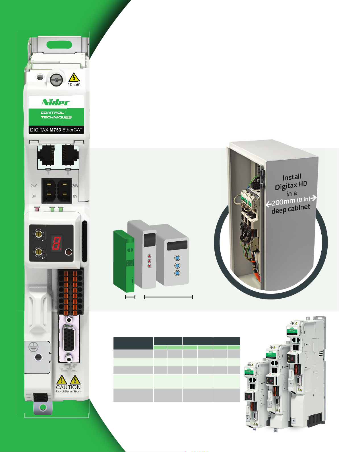
Minimum size
Actual size
servo solutions
Reduce cost and maximize floor space
Minimal footprint and exceptional power density
make Digitax HD one of the smallest servo drives
on the market today. This means that you can
build the most compact cabinets possible.
The market’s narrowest
servo drive
• Digitax HD is just 40mm (1.6 in) wide
• 25 drives, up to 16A per drive, can fi t in
just 1 meter (40 in) of cabinet space
Digitax HD
40mm (1.6 in)
Typical competitors
Drive dimensions
Dimensions Frame 1 Frame 2 Frame 3
in mm in mm in mm
Width 1.57 40 1.57 40 1.57 40
Depth 6.85 174 6.85 174 6.85 174
Height 9.17 233 11.0 278 12.9 328
Nominal current
@ 400 V
Peak current
@ 400 V
4.2 A 10.5 A 12.9 A
12.6 A 31.5 A 48 A
Just 40 mm (1.6 in)
6
6
Page 7
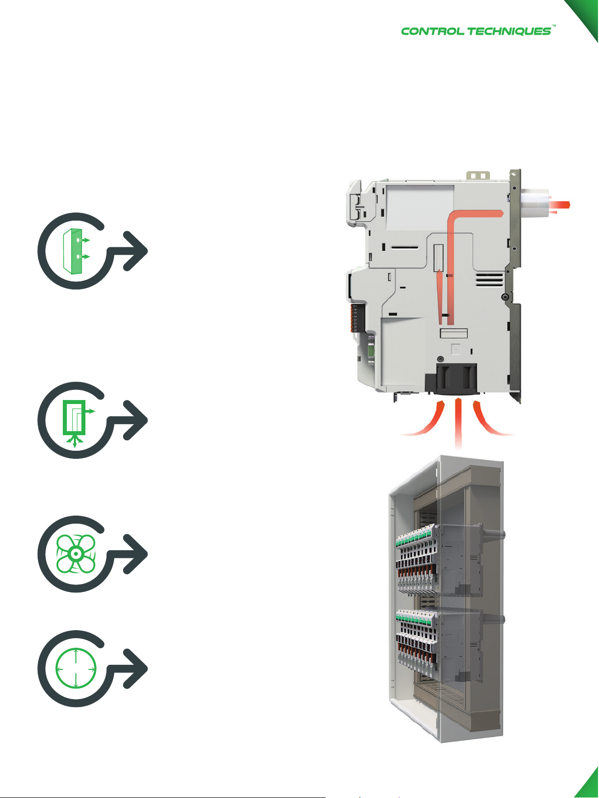
Further reduce cabinet size
with Ultraflow
TM
thermal management
Reduce cabinet height
by directly stacking
rows of drives. Control
Techniques’ patented
Ultrafl ow™ technology
expels heat directly
outside of the cabinet
through the rear of the
drive* and removes heat
build-up in the cabinet.
Ultrafl ow™’s guided
internal airfl ow prevents
32mm
ingress on drive circuits and,
combined with conformal
coating, minimizes
contamination risk.
An intelligently controlled
fan optimizes fan lifetime
and minimizes acoustic
noise, while contributing
to the maximum thermal
cooling by Ultrafl ow™.
Ultrafl ow™ requires only
a 32 mm (1.25 in) hole
in the cabinet meaning
rapid, trouble-free
installation**
Ultrafl owTM is a registered Trademark of Control Techniques
* Drive heat dissipation can also be achieved via vents on top of the drive, as standard.
** Frames 2 and 3 require 2 x 32mm (1.5 in) holes
DRIVE SPECIALISTS SINCE 1973
DRIVE SPECIALISTS SINCE 1973 7
7
Page 8
SERVO DRIVE SERIES
SERVO DRIVE SERIES
From
standalone...
...to a modular
common dc
bus system
SINGLE AC
INPUT
COMMUNICATION
LINKS
COMMON
DC BUS
AND EARTH
24 Vdc LINKS
8
8
Page 9
PERFORMANCE
SPEED
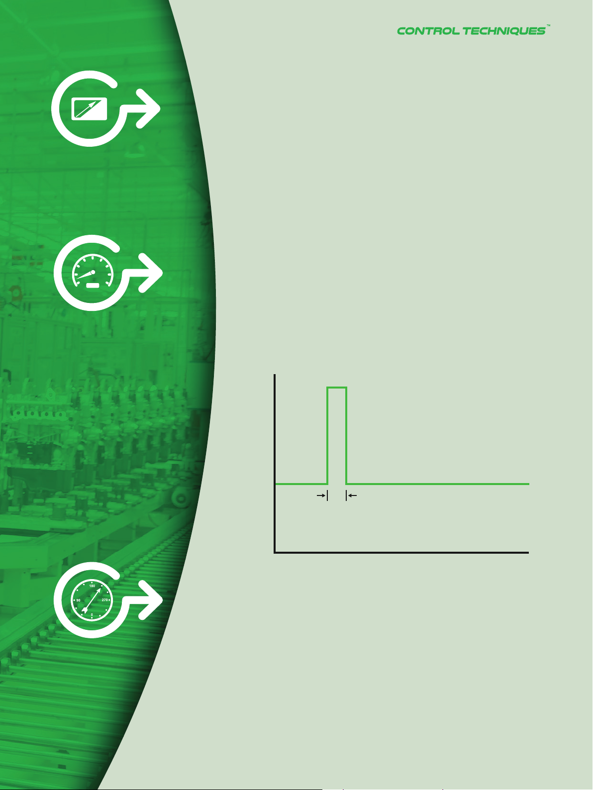
Maximum performance
servo solutions
Boost throughput with maximum control
Optimized for highly-dynamic applications and with
high speed control loops, Digitax HD brings maximum
throughput and production quality to your machines.
◼ 300% peak current performance
◼ Optimized control loops for high dynamic performance
– 62.5 μs current loop
– 250 μs position and speed loop
◼ Unique ‘dead beat’ current controller for maximum bandwidth
◼ Up to 16 kHz switching frequency (default ratings specifi ed at 8 kHz)
◼ Advanced bi-quad fi lters for suppression of mechanical
resonances
Current
300 %
PRECISION
I rated
250 ms
Time
Improving accuracy through precision
encoder feedback
The fl exible speed and position feedback interface
supports a wide range of feedback technologies, from
robust resolvers to high resolution encoders.
• Up to three onboard encoder channels simultaneously e.g.
1 feedback encoder, 1 reference encoder and 1 simulated output
• Quadrature, AB Servo, SinCos (including absolute), SSI, BiSS,
EnDat 2.1/2.2, Hiperface and resolvers
• Simulated encoder output can provide position reference
for cams, digital lock and electronic gearbox
• Up to 25 bit encoder resolution
• Feedback accuracy as low a ±20”
DRIVE SPECIALISTS SINCE 1973
DRIVE SPECIALISTS SINCE 1973 9
9
Page 10
SERVO DRIVE SERIES
SERVO DRIVE SERIES
DIN rail alignment
Remote mountable,
plain text,
multi-language
LCD keypad
Single cable
technology with
electronic motor
name plate for
fast setup
Rapid
installation and
commissioning
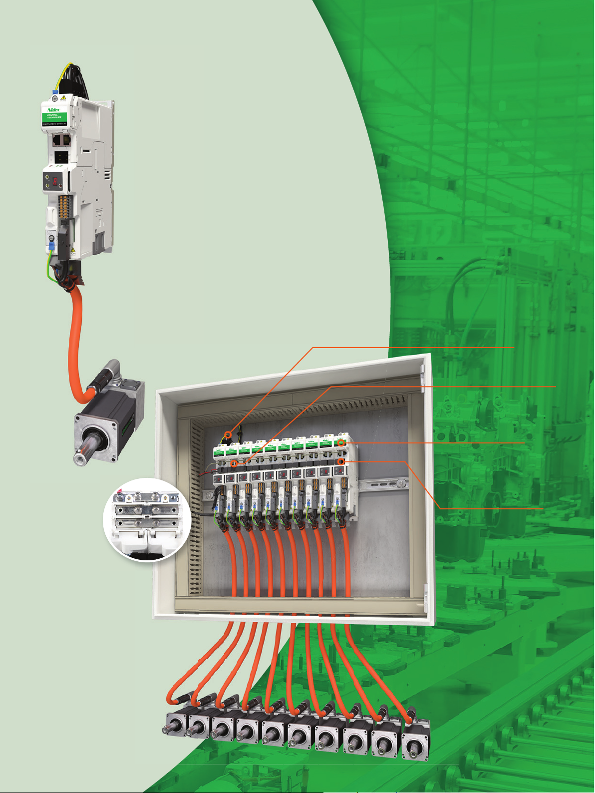
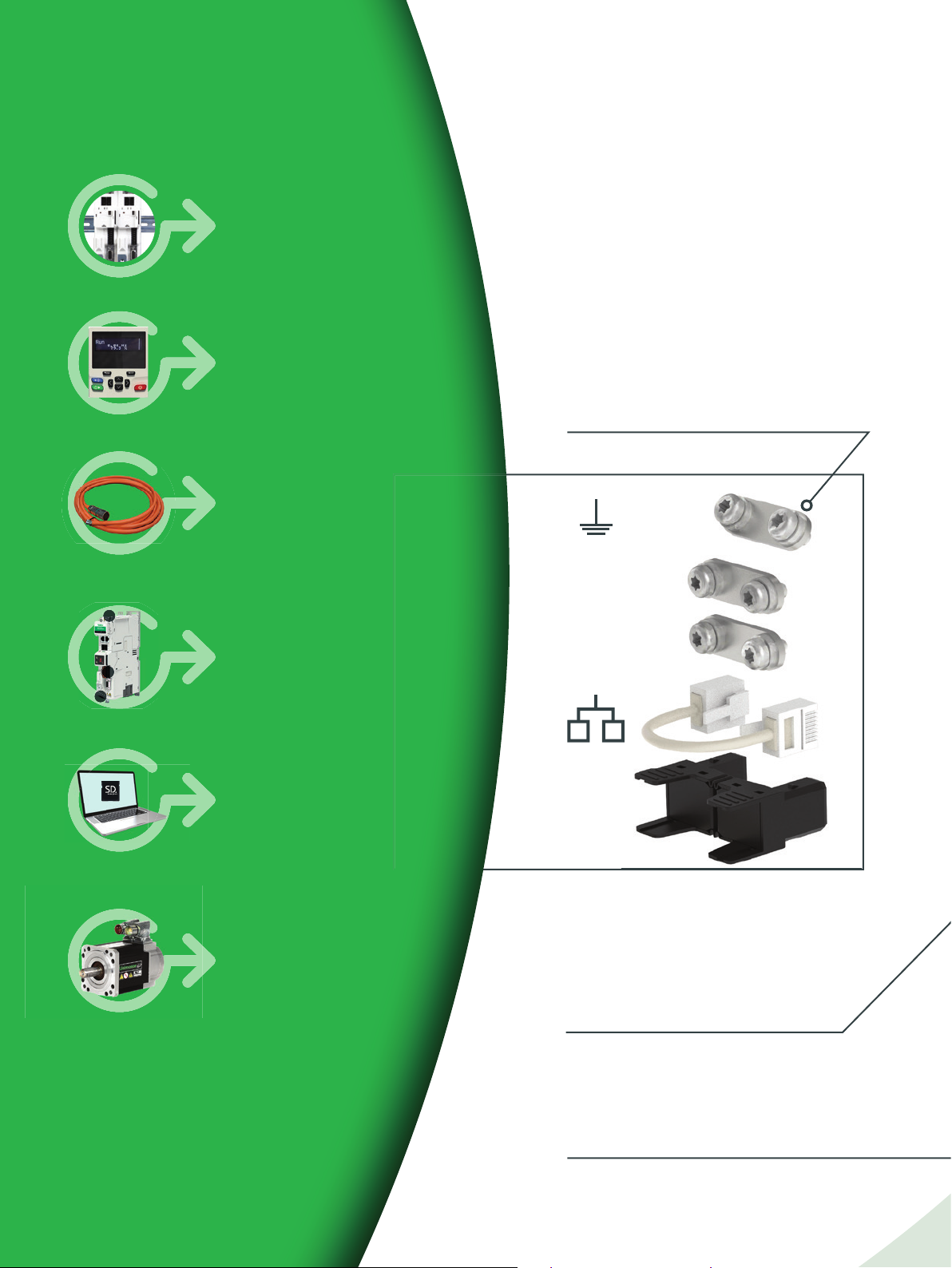
The multi-axis paralleling kit includes busbars
for quick connection of DC bus and earth link,
as well as Quick Links to distribute 24 Vdc
supply across drives.
• Reduces installation time and cost
• Improves energy effi ciency and footprint
Easy access
pluggable
connectors
Fast
commissioning
with PC tools or
SD cards
Unimotor’s electronic
nameplate provides
support for parameter
set-up between
motor and drive
+ DC
- DC
24 Vdc
The LED display ensures access to drive
diagnostics even in the absence of network
connectivity.
Includes 2 rotary switches for hardware
setting of the node address for faster
commissioning of the motion network.
10
10
The motor power connector is in the same
position for all frame sizes, making cable
routing easier and tidier.
Page 11
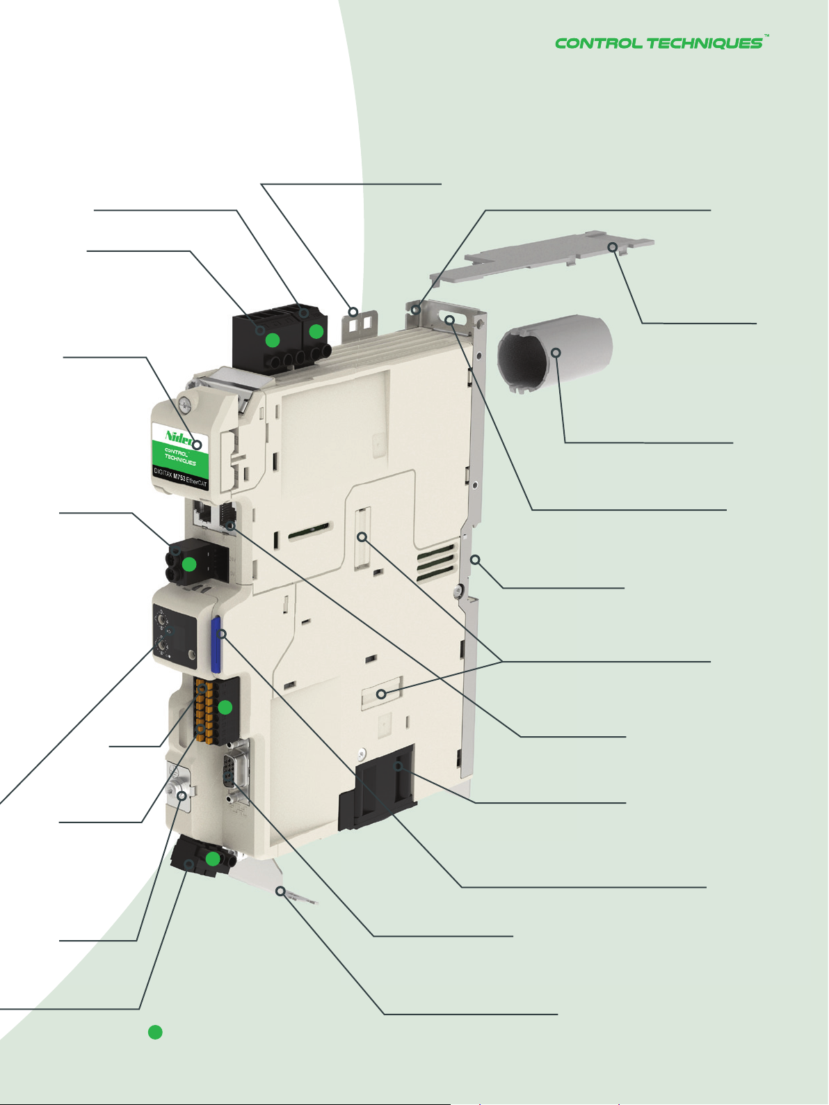
External Brake
Resistor Connector
AC input
Fixing points for cable ties on
the top, front and base of the
drive for compact wire routing
Drive alignment aid (alternative
to DIN rail alignment)
DC bus cover
24 Vdc Input
Ultrafl ow
cover (optional)
Rear duct for Ultrafl ow
thermal management
technology (optional)
Screw slot allows a fi xed
hole pattern to fi t any drive
combination.
DIN rail alignment
SI-Option module slots allow for
expansion of drive capabilities
TM
Vent
TM
I/O
Dual Safe
Torque Off
(STO)
Motor earth
Easy access pluggable connectors
Communication
ports
Easily replaceable fan
SD card slot for local backup, quick drive
replacement and repeat commissioning
Encoder input/output
Removable cable screen
bracket for quick installation
or replacement
DRIVE SPECIALISTS SINCE 1973
DRIVE SPECIALISTS SINCE 1973 11
11
Page 12

SERVO DRIVE SERIES
Fast programming
and commissioning
SOFTWARE
Application Programming
Machine Control Studio
The Machine Control Studio programming environment
provides a fl exible and intuitive environment for
programming automation and motion control features.
The software provides programming for:
◼ Onboard PLC
◼ MCi200 or MCi210 integrated machine control modules
◼ EtherNet network data confi gurations
Familiar automation programming languages
The programming environment is fully IEC 61131-3
compliant and therefore familiar, fast and easy to
use for control engineers around the world.
The following IEC 61131-3 programming
languages are supported:
◼ Structured Text (ST)
◼ Function Block Diagram (FBD)
◼ Structured Function Chart (SFC)
◼ Ladder Diagram (LD)
◼ Instruction List (IL)
◼ Continuous Function Chart (CFC)
Productivity features also supported:
◼ Intuitive IntelliSense functionality helps to
write consistent and robust programs
speeding up software development
◼ Programmers have access to a vibrant
Open-source community for function blocks
◼ Machine Control Studio also supports
customers’ own function block libraries
Features
Breakpoints - Yes
Source code
upload/download
Online change - Yes
Trigonometric
functions
64 bit data types - Yes
Real-time task(s) Yes (min 4ms) Yes (min 250 µs)
Customizable
drive menu
Variable tracing - Yes
Tasks available
Centralized
controller
Decentralized
controller
Digitax HD
onboard PLC
- Yes
- Yes
Yes Yes
1 x Freewheeling
task,
1 x Clock task
- Yes
Yes Yes
MCi Option Module
1 x Freewheeling task,
1 x Position task,
1 x Initial task,
4 x Clock tasks,
1 x Error task,
4 x Event tasks
12
Page 13
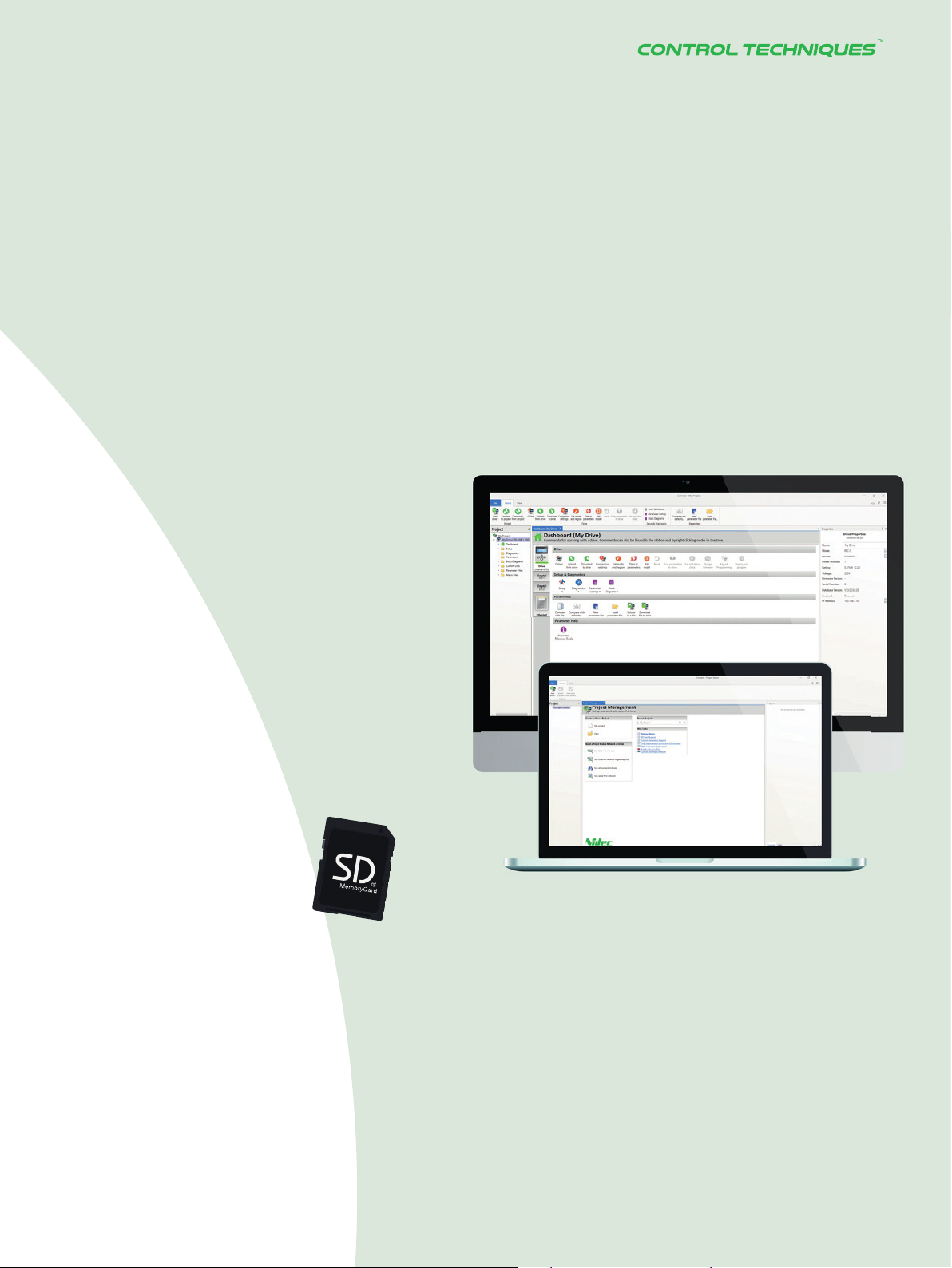
Commissioning
Connect
The Connect PC tool is for rapid
commissioning, plus optimizing and
monitoring drive/system performance.
◼ Task-based drive operations are simplifi ed with
intuitive graphical tools in a familiar Windows
environment
◼ CTScope – a realtime software oscilloscope –
facilitates tuning and monitoring
◼ Dynamic logic diagrams and searchable
parameter listings
◼ Tool is scalable, through optional add-ins, to
match application requirements
◼ Multiple communications channels for a more
complete overview of the system
◼ Drive discovery gives the ability to fi nd drives
on a network automatically without the user
having to specify their addresses
◼ Offl ine confi guration
SD card
Standard SD cards can be
used for quick and easy
parameter and program storage.
DRIVE SPECIALISTS SINCE 1973
13
Page 14
SERVO DRIVE SERIES
Motion Control
System Architecture
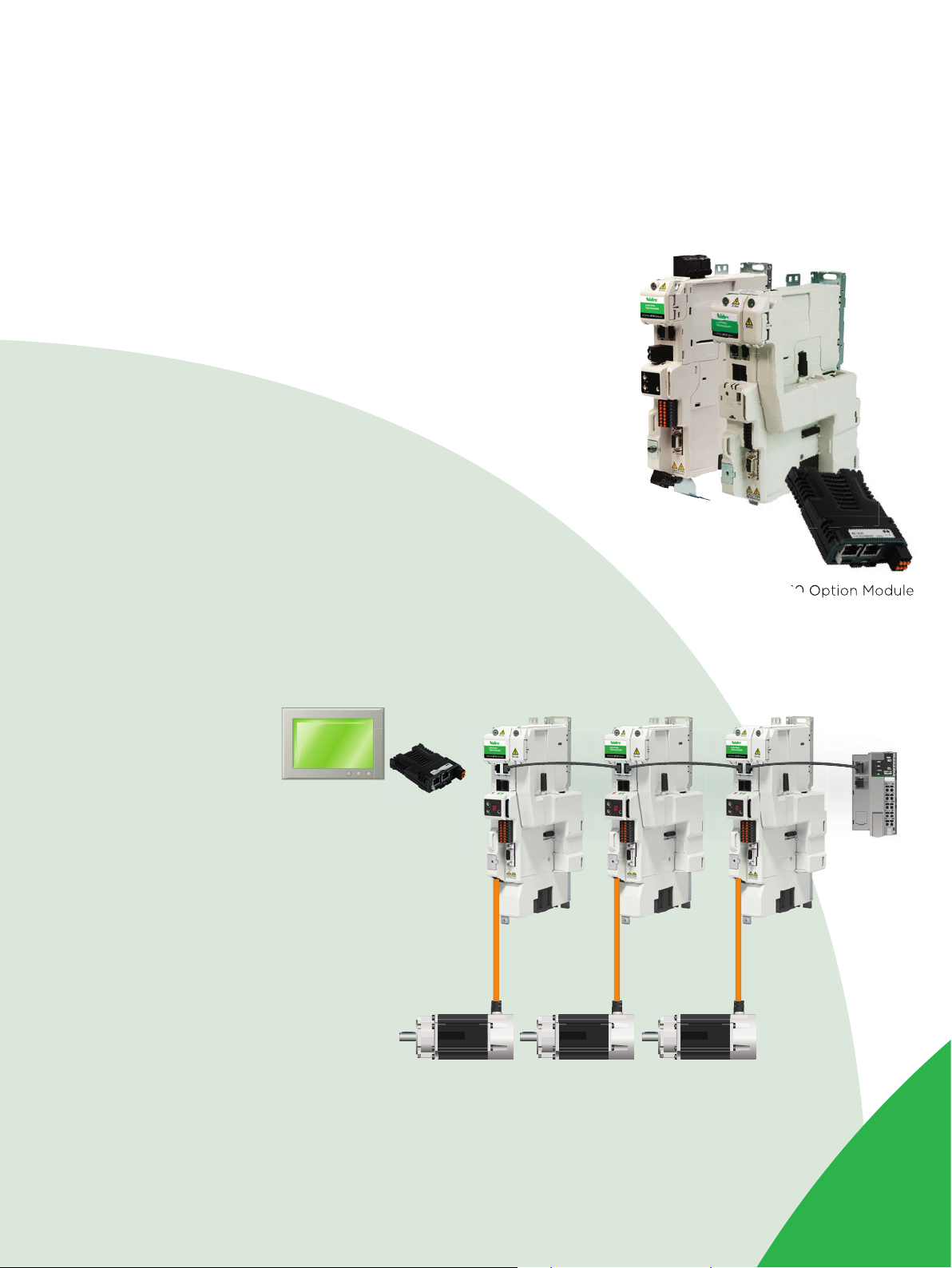
Drive-based Motion
(Decentralised/Distributed
Motion Intelligence)
In a distributed motion control system, the motion
control capability is distributed on-board the
individual drives. This includes the position loop,
motion profi le and sometimes even all or part of
the PLC logic.
◼ Each axis is fully independent, but coordination
can be achieved by synchronizing drives over
the network using Real-Time Motion over
EtherNet (RTMoE).
◼ In small machines, a drive-based system can be
standalone, whereas in larger systems it is more
commonly connected to a PLC (or IPC) over a
fi eldbus which, in this case, does not need to be
strictly deterministic.
M750 EtherNet
M751 Base
MCi210 Option Module
Key advantages
◼ A drive-based system off ers superior
motor control performance, as the
on-board loops typically run faster,
and it avoids the delays of network
communication.
◼ A distributed motion architecture can be
very cost-eff ective, as it forgoes the need
of an expensive central motion controller
and, by using the onboard logic, allows to
take some load off the central PLC.
◼ It is easily scalable, as the load of the
PLC, where present, does not increase
signifi cantly with the number of drives
connected.
◼ PC Tools provide similar ease of
commissioning and maintenance to a
centralised solution.
14
Page 15
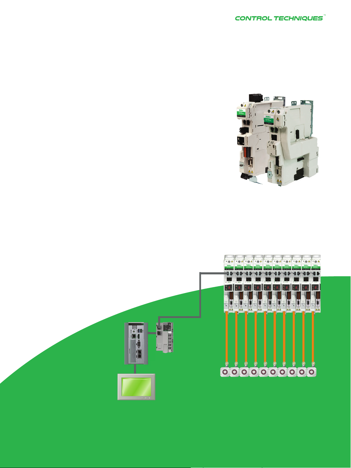
Controller-based Motion
(Centralized Motion
Intelligence)
A central controller generates the motion profi les of all axes
and in some cases even closes the position loop. In this
architecture the servo drives, often referred to as amplifi ers,
simply follow the setpoint they receive from the controller.
◼ The servo drives are normally connected over an EtherNet
network, using a fast and deterministic protocol such as
EtherCAT.
◼ In modern systems, the central controller, PLC-based or
IPC-based, tends to also implement all the machine logic.
Key advantages
◼ Ease of coordinating the motion of multiple axes in a single
program.
◼ Single storage location for the whole machine program,
and potentially even drive parameters, simplifying
maintenance.
M753 EtherCAT
M751 Base
DRIVE SPECIALISTS SINCE 1973
15
Page 16

SERVO DRIVE SERIES
SERVO DRIVE SERIES
M750
EtherNet
(multiprotocol)
Network drive for centralized
and decentralized motion
application
Digitax M750 EtherNet
Onboard multiprotocol EtherNet, supporting
Real Time Motion over EtherNet (RTMoE),
EtherNet/IP, Modbus TCP/IP and PROFINET RT
Onboard advanced motion controller for 1.5 axis
motion control
EtherNet webpages hosted onboard the M750
EtherNet drive
Reduced downtime with machine safety
- Integrated Dual Safe Torque Off
- Meets SIL3 and PLe
RTMoE
Digitax HD’s standard EtherNet supports
RTMoE (Real-Time Motion over EtherNet)
which provides synchronized communication
between drives using the Precision Time
Protocol as defi ned by IEEE1588 V2:
Distributed clocks are used to automatically
synchronize the position, speed and current
loops across all drives
High speed network synchronization of
less than 1 μs jitter (typically <200 ns) and
1 ms cycle time for synchronous cyclic data
Advanced Motion
Controller onboard
Advanced 1.5 axes motion controller,
key features include:
- 250 μs cycle time
- Motion profi le generator
- Electronic gearbox
- Interpolated cam
- Homing functions
- High speed position freeze
16
16
READY
4.0
PLe RTMoE
Page 17

Machine controllers
MCi200 & MCi210
Second processor for PLC
programs and multi-axis control CONTROL
MCi200 and MCi210 modules add a powerful
processor to Digitax HD. They extend the
drives system and machine control capability
to run application programs up to four times
faster than a standard PLC.
Programs are fast and easy to develop thanks to the
user-friendly Machine Control Studio software which uses
industry standard IEC 61131-3 programming languages.
MCi programs can access and manage the drive
embedded Advanced Motion Controller, providing
perfectly synchronized multi-axis machine performance.
Segregated network control
Network 1
DI8xDC24V
CPU314C-2 DP
AI5/A02x12Bit
SF
BF
DC5V
FRCE
RUN
STOP
PUSH
RUN
STOP
MRES
System Controller
DI16/D016xDC24V
0
0
1
1
2
2
3
3
4
4
5
5
6
6
7
7
DI+2 DI+0
IN IN OUT
DI+1
0
1
2
3
4
5
6
7
0
1
2
3
4
5
6
7
D0+0
D0+1
0
1
2
3
4
5
6
7
M751
• Two EtherNet ports with an internal switch
• Support for standard EtherNet protocols
• RTMoE for synchronized cyclic data at 250 µs
• Modbus TCP/IP master
• Machine control over two segregated EtherNet
networks enables greater fl exibility in machine design
• Extended fast I/O (3 x digital inputs, 1 x digital output,
1 x digital I/O)
Network 2
Machine 1
MCi Controller
MCi Controller
Network 3
M751
Machine 2
DRIVE SPECIALISTS SINCE 1973
17
Page 18

SERVO DRIVE SERIES
SERVO DRIVE SERIES
M751 Base
Base drive for
confi guration
fl exibility
Digitax M751 fl exibility
Two option slots for functionality extension
and customization – refer to page 21 for the
comprehensive option module list
Built-in Modbus RTU over RS485
communications
Onboard Advanced Motion Controller for
1.5 axis motion control
Analog and pulse/direction control for
centralized motion
Reduced downtime with machine safety
- Integrated Dual Safe Torque Off
- Meets SIL3 and PLe
Advanced Motion
Controller onboard
Advanced 1.5 axes motion controller,
key features include:
- 250 μs cycle time
- Motion profi le generator
- Electronic gearbox
- Interpolated cam
- Homing functions
- High speed position freeze
18
18
PLe
Page 19

M753
S
IL
3
Safety Integrity Level
EtherCAT
EtherCAT drive
for centralized
motion control
applications
Digitax M753 EtherCAT
Digitax M753 features an integrated 2-port
EtherCAT switch for easy integration in
centralized motion control applications
EoE (EtherNet over EtherCAT) support
allows PC tool connection for commissioning
and monitoring over the EtherCAT network
The station alias can be dynamically
assigned by the EtherCAT master, or
hardwired with the two rotary switches
built into the display
An optional RS485 adaptor is available,
providing a back-up PC tool connection
in case of network failure
High performance with fl exibility
Operate with any automation product
via EtherCAT
- Operate with motion controllers,
motion PLCs and Industrial PCs
via built-in EtherCAT
- Dual 100Mbps EtherCAT interfaces for
use with in-line topologies
- Non-cyclic data communication using
the CoE mailbox
Flexibility for all applications achieved
through full access to drive functions
- CANopen over EtherCAT (CoE) including:
> CIA-402 profi le
> Cyclic sync position mode
> Interpolated position mode
> Velocity mode
> Profi le torque mode
> SDO access to all profi le objects
and drive parameters
Reduced downtime with machine safety
- Integrated Dual Safe Torque Off
- Meets SIL3 and PLe
PLe
DRIVE SPECIALISTS SINCE 1973
DRIVE SPECIALISTS SINCE 1973 19
19
Page 20

SERVO DRIVE SERIES
SERVO DRIVE SERIES
Option module flexibility
Our innovative design means
you only increase drive size
when option modules are used,
therefore achieving signifi cant
space saving in the overall
confi guration.
20
20
Adding the option mounting
kit only adds an additional 22
mm (0.86 in) width, providing a
maximum drive width of 62 mm
(2.44 in).
Page 21

Option modules
Digitax HD supports a range of
communications, I/O, feedback and
machine control option modules.
Feedback
SI-Universal
Encoder
Encoder input and output
interface supporting
Quadrature, SinCos,
EnDat and SSI encoders.
I/O
SI-I/O
Extended I/O interface
module to increase the
number of analog and digital
I/O points on the drive.
Communications
SI-Encoder
Quadrature encoder
input interface module.
Applications with
PLC or Motion
Functionality
MCi200
Advanced machine
control using industry
standard IEC61131-3
programming languages
MCi210
Extended advanced machine
control using industry
standard IEC61131-3
programming languages
and integrated EtherNet
connectivity
SI-EtherCAT
SI-DeviceNet
* Support of real-time EtherNet (RTMoE), HTTP, SMTP, EtherNet/IP and Modbus TCP/IP
SI-PROFINET
SI-CANopen
SI-EtherNet*
SI-PROFIBUS
SI-Apps Compact
Compatible module
allows legacy SyPTPro
application programs
to be re-compiled for
Digitax HD
21DRIVE SPECIALISTS SINCE 1973 21
Page 22

SERVO DRIVE SERIES
SERVO DRIVE SERIES
Unimotor HD
High dynamic
servo motor
0.7 Nm to 85.0 Nm (6.2 lb-in to 752 lb-in)
and up to 300% overload
Unimotor HD is a high dynamic brushless
AC servo motor range designed for use in
pulse duty applications where rapid acceleration
and deceleration is required.
for pulse duty
applications
• Patented rotor
technology – High
torque to inertia ratio for
high dynamic performance
High torque to inertia ratio
Unimotor HD has a high power to weight ratio,
meaning that it can be easily integrated into the
smallest, most demanding applications such as
industrial robotics, pick & place and packaging.
• Compact but powerful
• Parking brake available
• IP65 conformance: sealed
against water spray and dust
when mounted and connected
• Segmented stator design for high
power density and compactness
• Supported by rigorous testing for
performance and reliability
• Windings to suit 400 V and 200 V
• Rated speeds include
1,000 rpm – 6,000 rpm
depending on motor size
• Customized motor build available
22
22
Page 23

DATA
Order information
and technical data
Motor & drive
combinations .............................24
Cables &
connections ................................ 33
Dimensioning
the common DC bus ............. 27
Specifi cations ........................... 35
Digitax HD kits
& accessories .............................28
Digitax HD
ordering information ............. 32
Unimotor HD
ordering information ............. 32
Drive ratings ............................... 36
Environmental
safety & conformance .......... 37
Digitax HD | Unimotor HD
dimensions .................................. 38
DRIVE SPECIALISTS SINCE 1973
DRIVE SPECIALISTS SINCE 1973 23
23
Page 24

SERVO DRIVE SERIES
Digitax HD & Unimotor HD
motor and drive combinations
400 V range – 0.7 to 51 Nm (6.2 to 451 lb-in) with 300% peak stall torque
200 V range – 0.7 to 45 Nm (6.2 to 398 lb-in) with 300% peak stall torque
1000.00 Nm
(8850 lb-in)
100.00 Nm
(885.0 lb-in)
10.00 Nm
(88.50 lb-in)
1.00 Nm
(8.85 lb-in)
Torque
134.2
(1187.8)
44.7
(395.6)
22.8
(201.8)
153.1
(1355)
51.0
(451.4)
22.8
(201.8)
67.2
(594.8)
22.4
(198.3)
10.0
(88.5)
103.7
(917.8)
34.6
(306.2)
10.0
(88.5)
44.6
(394.7)
14.9
(131.9)
0.7
(6.2)
76.8
(679.7)
25.6
(226.6)
0.7
(6.2)
23.3
(206.2)
7.8
(69.0)
3.1
(27.4)
23.3
(206.2)
7.8
(69.0)
3.1
(27.4)
22.6
(200.0)
7.5
(66.4)
0.7
(6.2)
23.3
(206.2)
6
7.8
5
(69.0)
0.7
(6.2)
Peak torque 200 VPeak torque 400 V
Stall torque 200 VStall torque 400 V
0.10 Nm
(0.89 lb-in)
200 V
400 V
1000 1500
200 V
400 V
200 V
400 V
200 V
400 V
200 V
2000 3000 4000 6000
Speed (rpm) and input voltage (V)
400 V
Page 25

200 V THREE PHASE
Nominal speed 6000 rpm - 300% overload
Stall Torque Peak Torque Inertia Drive
Motor Drive Hybrid Cable
055EDA60 M75x-01200022 HYBAxAxxx 0.69 6.1 2 .1 18.6 0.1 4 0.00012 2.2 580 0.43 0.58 8.5
055EDB60 M75x-01200040 HYBAxAxxx 1 .1 9.7 3.4 30.1 0.25 0.00022 4 580 0.57 0.76 9.2
055EDC60 M75x-01200040 HYBAxAxxx 1.6 14.2 4.8 42.5 0.36 0.00032 4 580 0.75 1.01 9.5
067EDA60 M75x-01200040 HYBAxAxxx 1.4 12.4 4.3 38.1 0.30 0.00027 4 580 0.82 1.10 8.8
067EDB60 M75x-01200065 HYBAxAxxx 2.5 22.1 7. 5 66.4 0.53 0.00047 6.5 580 1.4 1.88 8.9
089EDA60 M75x-02200090 HYBAxAxxx 3.1 27. 4 9.3 82.3 0.87 0.00077 6.5 1160 1.7 2.28 11.7
089EDB60 M75x-02200120 HYBAxAxxx 5.3 46.9 16.0 141.6 1.6 0.00142 12 1160 2.4 3.22 12.6
089EDC60 M75x-03200160 HYBBxAxxx 7.5 66.4 22.6 200.0 2.3 0.00204 16 1880 3.1 4.16 13.0
Motor Drive Hybrid Cable
089EDA40 M75x-01200065 HYBAxAxxx 3 .1 27. 4 9.3 82.3 0.87 0.00077 6.5 580 1.2 1.61 7.8
089EDB40 M75x-02200090 HYBAxAxxx 5.3 46.9 16.0 141.6 1.6 0.00142 9 1160 1.9 2.55 8.4
089EDC40 M75x-02200120 HYBAxAxxx 7.8 69.0 23.3 206.2 2.3 0.00204 12 1160 2.7 3.62 8.4
Motor Drive Hybrid Cable
055EDA30 M75x-01200022 HYBAxAxxx 0.69 6.1 2.1 18.6 0.14 0.00012 2.2 580 0.21 0.28 4.2
055EDB30 M75x-01200022 HYBAxAxxx 1.1 9.7 3.4 30.1 0.25 0.00022 2.2 580 0.32 0.43 4.6
067EDA30 M75x-01200022 HYBAxAxxx 1.4 12.4 4.3 38.1 0.30 0.00027 2.2 580 0.43 0.58 4.4
055EDC30 M75x-01200022 HYBAxAxxx 1.6 14.2 4.8 42.5 0.36 0.00032 2.2 580 0.45 0.60 4.8
067EDB30 M75x-01200040 HYBAxAxxx 2.5 22.1 7. 5 66.4 0.53 0.00047 4 580 0.75 1.01 4.4
089EDA30 M75x-01200040 HYBAxAxxx 2.8 24.8 8.4 74.3 0.87 0.00077 4 580 0.88 1.18 6.5
200 V Three phase
067EDC30 M75x-01200040 HYBAxAxxx 3.6 31.9 10.9 96.5 0.75 0.00066 4 580 1 .1 1.48 4.3
089EDB30 M75x-01200065 HYBAxAxxx 5.3 46.9 16.0 141.6 1.6 0.00142 6.5 580 1.5 2.01 6.3
089EDC30 M75x-02200090 HYBAxAxxx 7. 8 69.0 23.3 206.2 2.3 0.00204 9 1160 2.1 2.82 6.3
115EDB30 M75x-02200120 HYBAxAxxx 10.0 88.5 30.0 265.5 4.4 0.00389 12 1160 2.4 3.22 9.2
115EDC30 M75x-03200160 HYBBxAxxx 14.3 126.6 42.9 379.7 6.4 0.00566 16 1880 3.2 4.29 9.4
142EDC30 M75x-03200160 HYBBxBxxx 14.9 131.9 44.6 394.7 17. 0 0.01505 16 1880 4.7 6.30 23.9
[Nm] [lb-in] [Nm] [lb-in] [kg·cm2] [lb-in-sec2]
Nominal speed 4000 rpm - 300% overload
Stall Torque Peak Torque Inertia Drive
[Nm] [lb-in] [Nm] [lb-in] [kg·cm2] [lb-in-sec2]
Nominal speed 3000 rpm - 300% overload
Stall Torque Peak Torque Inertia Drive
[Nm] [lb-in] [Nm] [lb-in] [kg·cm2] [lb-in-sec2]
Cont.
Current
[A]
Cont.
Current
[A]
Cont.
Current
[A]
Drive
Capacitance
[μF]
Drive
Capacitance
[μF]
Drive
Capacitance
[μF]
Motor Cont.
power
[kW] [hp]
Motor Cont.
power
[kW] [hp]
Motor Cont.
power
[kW] [hp]
Time to
6000 rpm
[ms]*
Time to
4000 rpm
[ms]*
Time to
3000 rpm
[ms]*
Nominal speed 2000 rpm - 300% overload
Stall Torque Peak Torque Inertia Drive
Motor Drive Hybrid Cable
115EDB20 M75x-02200090 HYBAxAxxx 10.0 88.5 30.0 265.5 4.4 0.00389 9 1160 1.8 2.41 6.2
115EDC20 M75x-02200120 HYBAxAxxx 14.3 126.6 42.9 379.7 6.4 0.00566 12 1160 2.4 3.22 6.2
115EDD20 M75x-03200160 HYBBxAxxx 18.4 162.9 55.3 489.4 8.4 0.00743 16 1880 3.2 4.29 6.4
142EDC20 M75x-03200160 HYBBxBxxx 22.4 198.3 67.2 594.8 17. 0 0.01505 16 1880 4.1 5.50 10.6
Motor Drive Hybrid Cable
142EDC10 M75x-02200090 HYBAxAxxx 22.8 201.8 68.3 604.5 17. 0 0.01505 9 1160 2.2 2.95 5.2
142EDD10 M75x-02200120 HYBAxAxxx 28.7 254.0 86.0 761.2 22.1 0.01956 12 1160 2.8 3.75 5.4
142EDE10 M75x-03200160 HYBBxAxxx 34.6 306.2 103.7 917.8 2 7.2 0.024 07 16 1880 3.3 4.43 5.5
190EDC10 M75x-03200160 HYBBxBxxx 44.7 395.6 134.2 1187.8 54.6 0.04833 16 1880 4.7 6.30 8.5
[Nm] [lb-in] [Nm] [lb-in] [kg·cm2] [lb-in-sec2]
Nominal speed 1000 rpm - 300% overload
Stall Torque Peak Torque Inertia Drive
[Nm] [lb-in] [Nm] [lb-in] [kg·cm2] [lb-in-sec2]
For drive ratings, please see page 34 and motor ratings from page 38 to 43
* Acceleration time to nominal speed is based on 1:1 motor to load inertia ratio
Cont.
Current
[A]
Cont.
Current
[A]
Drive
Capacitance
[μF]
Drive
Capacitance
[μF]
Motor Cont.
power
[kW] [hp]
Motor Cont.
power
[kW] [hp]
DRIVE SPECIALISTS SINCE 1973www.controltechniques.com24 25
Time to
2000 rpm
[ms]*
Time to
1000 rpm
[ms]*
Page 26

SERVO DRIVE SERIES
400 V THREE PHASE
Nominal speed 6000 rpm - 300% overload
Stall Torque Peak Torque Inertia Drive
Motor Drive Hybrid Cable
055UDA60 M75x-01400015 HYBAxAxxx 0.69 6.1 2 .1 18.6 0.1 4 0.00012 1.5 110 0.43 0.6 8.5
055UDB60 M75x-01400015 HYBAxAxxx 1.1 9.7 3.4 3 0.1 0.25 0.00022 1.5 110 0.57 0.8 9.2
055UDC60 M75x-01400030 HYBAxAxxx 1.6 14.2 4.8 42.5 0.36 0.00032 4.2 110 0.75 1.0 9.5
067UDA60 M75x-01400030 HYBAxAxxx 1.4 12.4 4.3 38.1 0.30 0.00027 4.2 110 0.82 1.1 8.8
067UDB60 M75x-01400042 HYBAxAxxx 2.5 22.1 7. 5 66.4 0.53 0.00047 4.2 110 1.4 1.9 8.9
067UDC60 M75x-02400060 HYBAxAxxx 3.6 31.9 10.9 96.5 0.75 0.00066 6.0 290 1.9 2.5 8.7
089UDA60 M75x-01400042 HYBAxAxxx 3.1 27. 4 9.3 82.3 0.87 0.00077 4.2 110 1.7 2.3 11.7
089UDB60 M75x-02400080 HYBAxAxxx
089UDC60 M75x-02400105 HYBBxAxxx 7. 8 69.0 23.3 206.2 2.3 0.00204 10.5 290 3.1 4.2 12.6
Motor Drive Hybrid Cable
089UDA40 M75x-01400030 HYBAxAxxx 3.1 2 7.4 9.3 82.3 0.87 0.00077 4.2 110 1.2 1.6 7. 8
089UDB40 M75x-02400060 HYBAxAxxx 5.3 46.9 16.0 141.6 1.6 0.00142 6.0 290 1.9 2.5 8.4
089UDC40 M75x-02400080 HYBAxAxxx 7. 8 69.0 23.3 206.2 2.3 0.00204 8.0 290 2.7 3.6 8.4
Motor Drive Hybrid Cable
055UDA30 M75x-01400015 HYBAxAxxx 0.69 6.1 2.1 18.6 0.14 0.00012 1.5 110 0.21 0.3 4.2
055UDB30 M75x-01400015 HYBAxAxxx 1.1 9.7 3.4 30.1 0.25 0.00022 1.5 110 0.32 0.4 4.6
055UDC30 M75x-01400015 HYBAxAxxx 1.6 14.2 4.8 42.5 0.36 0.00032 1.5 110 0.45 0.6 4.8
067UDA30 M75x-01400030 HYBAxAxxx 1.4 12.4 4.3 38.1 0.30 0.00027 4.2 110 0.43 0.6 4.4
067UDB30 M75x-01400015 HYBAxAxxx 2.4 21.2 7. 2 63.7 0.53 0.00047 1.5 110 0.75 1.0 4.6
067UDC30 M75x-01400030 HYBAxAxxx 3.6 31.9 10.9 96.5 0.75 0.00066 4.2 110 1.1 1.5 4.3
089UDA30 M75x-01400030 HYBAxAxxx 3.1 27. 4 9.3 82.3 0.87 0.00077 4.2 110 0.91 1.2 5.9
400 V Three phase
089UDB30 M75x-01400042 HYBAxAxxx
089UDC30 M75x-02400060 HYBAxAxxx 7. 8 69.0 23.3 206.2 2.3 0.00204 6.0 290 2 .1 2.8 6.3
115UDB30 M75x-02400080 HYBAxAxxx 10.0 88.5 30.0 265.5 4.4 0.00389 8.0 290 2.4 3.2 9.2
115UDC30 M75x-02400105 HYBBxAxxx 14.3 126.6 42.9 379.7 6.4 0.00566 10.5 290 3.2 4.3 9.4
115UDD30 M75x-03400135 HYBBxAxxx 18.4 162.9 55.3 489.4 8.4 0.00743 13.5 470 4.2 5.6 9.5
142UDC30 M75x-03400160 HYBBxAxxx 22.8 201.8 68.3 604.5 1 7.0 0.01505 16.0 470 5.3 7.1 15.7
142UDD30 M75x-03400160 HYBBxBxxx 25.6 226.6 76.8 679.7 22.1 0.01956 16.0 470 6.0 8.0 18.1
[Nm] [lb-in] [Nm] [lb-in] [kg·cm
5.3 46.9 16.0 141.6 1.6 0.00142 8.0 290 2.4 3.2 12.6
Nominal speed 4000 rpm - 300% overload
Stall Torque Peak Torque Inertia Drive
[Nm] [lb-in] [Nm] [lb-in] [kg·cm
Nominal speed 3000 rpm - 300% overload
Stall Torque Peak Torque Inertia Drive
[Nm] [lb-in] [Nm] [lb-in] [kg·cm
5.3 46.9 16.0 141.6 1.6 0.00142 4.2 110 1.5 2.0 6.3
2
] [lb-in-sec2]
2
] [lb-in-sec2]
2
] [lb-in-sec2]
Cont.
Current
[A]
Cont.
Current
[A]
Cont.
Current
[A]
Drive
Capacitance
[μF]
Drive
Capacitance
[μF]
Drive
Capacitance
[μF]
Motor Cont.
power
[kW] [hp]
Motor Cont.
power
[kW] [hp]
Motor Cont.
power
[kW] [hp]
Time to
6000 rpm
[ms]*
Time to
4000 rpm
[ms]*
Time to
3000 rpm
[ms]*
Nominal speed 2000 rpm - 300% overload
Stall Torque Peak Torque Inertia Drive
Motor Drive Hybrid Cable
115UDB20 M75x-01400042 HYBAxAxxx 10.0 88.5 30.0 265.5 4.4 0.00389 4.2 110 1.8 2.4 6.2
115UDC20 M75x-02400060 HYBAxAxxx 14.3 126.6 42.9 379.7 6.4 0.00566 6.0 290 2.4 3.2 6.2
115UDD20 M75x-02400080 HYBAxAxxx 18.4 162.9 55.3 489.4 8.4 0.00743 8.0 290 3.2 4.3 6.4
142UDC20 M75x-02400105 HYBBxAxxx 22.8 201.8 68.3 604.5 17. 0 0.01505 10.5 290 4.1 5.5 10.4
142UDD20 M75x-03400135 HYBBxAxxx 28.7 254.0 86.0 761.2 22.1 0.01956 13.5 470 4.9 6.6 10.8
142UDE20 M75x-03400160 HYBBxAxxx 34.6 306.2 103.7 917.8 27.2 0.02407 16.0 470 5.6 7. 5 11.0
Motor Drive Hybrid Cable
142UDC15 M75x-02400080 HYBAxAxxx 22.8 201.8 68.3 604.5 1 7.0 0.01505 8.0 290 3.2 4.3 7.8
142UDD15 M75x-02400105 HYBAxAxxx 28.7 254.0 86.0 761.2 22.1 0.01956 10.5 290 3.9 5.2 8.1
142UDE15 M75x-03400135 HYBAxAxxx 34.6 306.2 103.7 917.8 2 7.2 0.024 07 13.5 470 4.5 6.0 8.2
190UDC15 M75x-03400160 HYBBxBxxx 51.0 451.4 153.1 1355.0 54.6 0.04833 16.0 470 7. 3 9.8 11.2
[Nm] [lb-in] [Nm] [lb-in] [kg·cm
Nominal speed 1500 rpm - 300% overload
Stall Torque Peak Torque Inertia Drive
[Nm] [lb-in] [Nm] [lb-in] [kg·cm
For drive ratings, please see page 36 and motor ratings from page 40 to 45.
* Acceleration time to nominal speed is based on 1:1 motor to load inertia ratio
26
2
] [lb-in-sec2]
2
] [lb-in-sec2]
Cont.
Current
[A]
Cont.
Current
[A]
Drive
Capacitance
[μF]
Drive
Capacitance
[μF]
Motor Cont.
power
[kW] [hp]
Motor Cont.
power
[kW] [hp]
Time to
2000 rpm
[ms]*
Time to
1500 rpm
[ms]*
Page 27

Modular multi-axis configuration
* External AC Line Reactor required. Please refer to the Installation and Technical Guide.
ADDITIONAL
Dimensioning the common DC bus
4 easy steps to
1
1
2
4
3
Digitax HD drives have a high capacity input power stage,
allowing for a group of drives on a common DC bus to be
powered by a single AC connection.
Alternatively, for larger confi gurations an external DC
source can be used, such as a larger frame Unidrive M.
NOTE: The number of drives that can be connected on
a common DC bus group depends on the total
installed capacitance, the power
rating of the input stage and
the power profi le of each axis.
There is also a limit of
10 drives for the 24 Vdc link.
ADDITIONAL
INFORMATION:
For optimized dimensioning
please refer to the Installation
and Technical Guide.
accurately dimension
your system
Choose drive & motor combination
1
based on speed and torque
requirements see pages 25 and 26
Note nominal power & drive
2
capacitance for each combination
Choose the drive to act as power
3
supply for the drive group
Usually the largest drive
Check that:
4
1. sum of drive capacitance
<= maximum capacitance**
2. sum of nominal power
<= maximum input power**
(Refer to tables below)
Max
200V
M75x-01200022
Size 1
M75x-01200040
M75x-01200065
M75x-02200090
Size 2
M75x-02200012
Size 3 M75x-03200160 376 0 1880 6.3 / 10* 8.5 / 13.4*
400V
M75x-01400015
Size 1
M75x-01400030
M75x-01400042
M75x-02400060
Size 2
M75x-02400080
M75x-02400105
M75x-03400135
Size 3
M75x-03400160
Capacitance
(µF)
5800 580 4 / 5.2* 5.4 / 7.0*
4640 1160 5.3 / 6.9* 7.1 / 9.3*
Max
Capacitance
(µF)
1900 110 6.5 / 8.5* 8.7 / 11.4*
2030 290 8.7 / 11.4* 11.7 / 15.3*
2210 470 10 / 13* 13.4 / 17.4*
Internal
Capacitance
(µF)
Internal
Capacitance
(µF)
Max
Input
Power
(kW)
Max
Input
Power
(kW)
Max Input
Power
(hp)
Max Input
Power
(hp)
* External AC Line Reactor required. Please refer to the Installation and Technical Guide.
** If any of the values are exceeded, the system needs to be split in groups and the
procedure repeated for each group.
DRIVE SPECIALISTS SINCE 1973
27
Page 28

SERVO DRIVE SERIES
SERVO DRIVE SERIES
Multi-axis Kit
Description Order code
Multi-axis Kit (standard – without
SI-Option Mounting Kit fi tted)
Multi-axis Kit (with SI-Option
Mounting Kit fi tted)
Description Order code
External Cable Grommet Kit up
External DC Cable Connection
Kit up to 16mm
to 6mm
2
2
Digitax HD
kits and accessories
9500-1047
9500-1048
3470-0145
9500-1050
Description Order code
USB to EIA485 Communications
Converter Cable
Description Order code
KI-Compact 485 Adaptor 82700000020300
Description Order code
KI-Compact Display 82700000020400
4500-0096
Standard cables available
Description Order code
Refer to pages 33 and 34
28
28
Page 29

Description Order code
Input Line Choke 4401-0236
Description Order code
Remote Keypad RTC 82400000019600
Description Order code
TM
Frame 1 Rear Ultrafl ow
Frame 2/3 Rear Ultrafl ow
Vent Kit
Retrofi t Kit – Epsilon 202-206 3470-0185
Retrofi t Kit – Epsilon 209-216 3470-0184
Retrofi t Kit – Digitax ST/SP0 3470-0182
Retrofi t Kit – M’Ax 3470-0183
Description Order code
SI-Option Mounting Kit 9500-1055
Vent Kit 3470-0158
TM
Description Order code
3470-0181
Drive – Mountable Brake Resistor
Description Order code
Compact Brake Resistor Kit – 50 W, 70 Ω 9500-1049
External Brake Resistor
Description Order code
External Brake Resistor – DBR 100 W, 20 Ω 1220-2201
External Brake Resistor – DBR 100 W, 40 Ω 1220-2401
External Brake Resistor – DBR 100 W, 80 Ω 1220-2801
Description Order code
Fan Replacement Kit (frame 1 and 2) 9500-1053
Fan Replacement Kit (frame 3) 9500-1054
Description Order code
Encoder breakout kit 82700000020200
DRIVE SPECIALISTS SINCE 1973
DRIVE SPECIALISTS SINCE 1973 29
29
Page 30

SI-PROFIBUS
SI-Encoder
SI-DeviceNet
SI-CANopen
SI-EtherNet
SI-PROFINET RT
SI-Universal Encoder
MCi200
MCi210
SI-I/O
SI-Apps Compact
SERVO DRIVE SERIES
Digitax HD
kits and
accessories
EMC Filters
Voltage Model (M75X-...) Phases Order code
1200022 1
4200-35031200040 1
1200065 1
2200090 1
2200120 1
200 V
400 V
* EMC fi lter ratings provided at maximum continuous current at 40 °C
(104 °F). Please refer to the installation and Technical Guide.
3200160 1 4200-6034
1200022 3 4200-8744
1200040 3 4200-6002
1200065 3 4200-6001
2200090 3 4200-5833
2200120 3 4200-5833
3200160 3 4200-5833
01400015 to 01400042 3 4200-8744
02400060 to 02400105 3 4200-1644
03400135 to 03400160 3 4200-5833
* Multi-axis up to 46 A 4200-0033
* Multi-axis up to 60.2 A 4200-5534
* Multi-axis up to 82.2 A 4200-7534
* Multi-axis up to 109.5 A 4200-0035
4200-5033
In the box for each Digitax HD M75x
Description Part Number
KI-Compact Display 82700000020400 Ye s No Ye s N /A
SI-Option Mounting Kit 9500-1055 No Yes No N/A
Removable cable screen bracket
Brake Connector Yes Yes Ye s N /A
Power Input Connector Yes Yes Ye s N /A
24 Vdc Supply Input Connector Yes Yes Ye s Ye s
I/O Connector Yes Yes Ye s N /A
Motor Connector Yes Ye s Yes N/A
M4 x 8 Screws (Motor earth, Input
earth and cable screen bracket)
N/A
M750
EtherNet
Yes Yes Ye s N /A
Yes Yes Ye s N /A
M751
Base
M753
EtherCAT
M75C
CapShare
30
Description Order code
DC bus conn. kit -
Unidrive M fr03 (panel mount)
DC bus conn. kit -
Unidrive M fr03 (through mount)
DC bus conn. kit -
Unidrive M fr06 (panel mount)
DC bus conn. kit -
Unidrive M fr06 (through mount)
System Integration Option Modules
Option Order code
MCi200 82400000017000
MCi210 82400000016700
SI-Apps Compact 82400000020700
SI-EtherNet 82400000017900
SI-PROFINET RT 82500000018200
SI-PROFIBUS 82400000017500
SI-CANopen 82400000017600
SI-DeviceNet 82400000017700
SI-Universal Encoder 82400000018300
SI-Encoder 82400000018100
SI-I/O 82400000017800
SI-EtherCAT 82400000018000
3470-0146
3470-0147
3470-0148
3470-0149
Page 31

M75C CapShare
Capacitor Module
DIN rail
alignment
Status LED
Top vent
for natural
convection
cooling
Common DC
bus links &
parallel
connection
24 Vdc
parallel
connection
Status
relay
contacts
M75C Capabilities
Available in 200 V and 400 V
variants, the M75C CapShare Capacitor
Module is contained within a M75x Frame
1 chassis measuring 40mm width. M75C
CapShare is designed for use in multi-axis
applications to off er:
◼ Robustness against fl uctuations in power
supply, increasing the ability to ride through
brief mains losses
◼ Dynamic performance with quick-access energy
storage for fast acceleration / deceleration
◼ Energy effi ciency as more energy can be stored,
rather than dissipated into heat
Multiple M75C CapShare units can be paralleled in
a scalable architecture, which is also quick and easy
to install with DIN rail alignment, and easy DC bus
paralleling.
M75C CapShare Capacitor Module
Part Number M75C-01201740 M75C-01400725
Rated Voltage 200 V 400 V
Energy efficiency
◼ Easy common DC bus connection enables braking
energy to be recycled within the drive system,
optimizing energy useage.
◼ Any Digitax HD drive can be used as an Active Front
End (AFE) to create a regenerative AC drive system.
Active Front End kits
Voltage Model (M75X-…) Switching Frequency Filter
2200090 1610-8104 4401-0310 4401-1311
200 V
400 V
2200120 1610-8104 4401-0312 4401-1312
3200160 1610-8104 4401-0313 4401-1313
2400080 1610-8104 4401-0405 4401-0162
2400105 1610-8104 4401-0406 4401-0163
3400135 1610-8104 4401-0407 4401-0164
3400160 1610-8104 4401-0407 4401-0164
Capacitors
Order Codes Order Codes Order Codes
Onboard capacitance 1740 µF 725 µF
DC supply 200-370 Vdc 360-760 Vdc
External 24 Vdc supply for control Yes
Internal Current Inrush limitation Circuit Yes
Status Relay (Potential Free Contacts) Yes
Status Indication On Front Panel Single LED
Thermal Protection Yes
Easy connection to a drive or drive group can be achieved with the
multiaxis kit (9500-1048) – no additional fusing required.
Regenerative Choke Switching Frequency Filter
Choke
DRIVE SPECIALISTS SINCE 1973
31
Page 32

SERVO DRIVE SERIES
Digitax HD ordering information
Drive part number key:
Identification Label
Derivative
Electrical Specification
Configuration
M753 - A 101 2 00022
Digitax HD range
M750 - EtherNet
M751 – Base
M753 – EtherCAT
Frame Size:
01 – frame 1
02 – frame 2
03 – frame 3
Voltage Rating:
2-200 V (200-240 ± 10%)
4-400 V (380-480 ± 10%)
Current Rating:
Nominal current rating x 10
Safety:
1 – Standard (2 x STO)
*For EtherNet and MCi versions, Option Modules are required separately. See page 29 for order codes.
Encoder
Interface
0
Documentation
1 00
Default
Region:
00 - 50 Hz
01 - 60 Hz
Optional Build
A 1B 1 0
Display option:
0 – KI-Compact Display not fitted
1 – KI-Compact Display fitted –
M750 and M753 only
Option module support:
AB10 – Not fitted
AB11 – Fitted – M751 only
Documentation:
1 – Multilingual
Encoder Interface:
0 – Standard
Unimotor HD ordering information
Motor part number key:
Frame
size
089
055
067
089
115
142
190
ED = 200V
UD = 400V
Motor
voltage
Stator
length*
Rated
speed
UD 0 B
055-
067
A
B
C
089
A
B
C
115
B
C
D
142
C
D
E
190
C
D
F
055 Frame
30 = 3000 rpm
60 = 6000 rpm
067 Frame
30 = 3000 rpm
60 = 6000 rpm
089 Frame
30 = 3000 rpm
40 = 4000 rpm
60 = 6000 rpm
115 Frame
20 = 2000 rpm
30 = 3000 rpm
142 Frame
10 = 1000 rpm
15 = 1500 rpm
20 = 2000 rpm
30 = 3000 rpm
190 Frame
10 = 1000 rpm
15 = 1500 rpm
20 = 2000 rpm
Brake Connection
0 = Not fitted
5 = Parking
Brake (fibre)
6 = Parking
Brake (resin)
x = Special
Size 1
B = Power and signal
90° rotatable
D= Single cable, power
& Signal combined,
90° rotatable
Size 1.5
J = Power and signal 90°
rotatable
E = Single cable, power
& signal combined,
90° rotatable
Single cable only must be
fitted with KTY thermistor
and is only available with
certain feedback options.
Please check before
ordering.
1
type*
Output shaft Feedback
device
A CA30
A = Key
B = Plain
E = Key with half
F = Key and half key supplied separately
Code Type Incremental
2
key fitted
055 and 067 frame sizes
resolution
AR Resolver 14 bit - ±600” no
EG Absolute (Multi turn) 19 bit 12 bit ±120” yes
FG Absolute (Single turn) 19 bit - ±120” yes
TL Absolute (Multi turn) 17 bit 12 bit ±120” no
UL Absolute (Single turn) 17 bit - ±120” no
089 to 190 frame sizes
AE Resolver 14 bit - ±720” no
EF Absolute (Multi turn) 19 bit 12 bit ±65” yes
FF Absolute (Single turn) 19 bit - ±65” yes
RA Absolute (Multi turn) 20 bit 12 bit ±52” no
SA Absolute (Single turn) 20 bit - ±52” no
A = Standard + PTC
C = Standard inertia +
2
E = Standard + PTC
Absolute
resolution
KTY84-130
Thermistor
Thermistor + Lifting
brackets (190 frame)
Accuracy Single
Inertia +
thermistor
type
AB
cable
*For stator length and connection type see pages 38 - 43
1
not available for 055 & 190 frames
2
n
ot available on 055 frame.
32
Additional feedback options available on request.
Page 33

Cables and connections
Power cable part number key:
FIELD NUMBER
1 32 4 5 76 8 9 1110 12
M BB A A OA O 2 S5 S
Cable & jacket type (field No 1,2 &3)
MBB = power braked
4 w + 2 w + screen, PUR jacket
MSB = power
4 w + screen, PUR jacket
Phase & conductor size (field No 4)
MSB = Un-braked MBB = Braked
2
A = 1 mm
B = 2.5 mm
C = 4 mm + 1 mm
D = 6 mm + 1 mm
E = 10 mm + 1 mm
F = 16 mm + 1 mm
G = 25 mm + 1 mm
*Length meter / cable requiring (cm) lengths will be rounded up to the next highest half meter; Eg. 2.1 will be changed to a 2.5 meter cable.
Maximum cable length refer to page 34
2
+ 0.5 mm
+ 0.5 mm
2
2
Drive end connection * (field No 5)
A = Ultrasonic welding
X = Cut end
Length meter * (field No 7, 8, 9 & 10)
0010 = 1 meter
0025 = 2.5 meter
0500 = 50 meters
Motor end connection (field No 6)
A = 6 way power size 1 from 1 to 4 mm
C = 6 way power size 1.5 from 6 to 16 mm
X = Cut end
Optional:
Progressive alphanumeric
code for custom special
requests (field No 11 & 12)
2
Signal cable part number key:
FIELD NUMBER
1 32 4 5 76 8 9 1110 12
S BI A B OA O 2 S5 S
Jacket type (field No 3)
A = PVC fixed installation
B = PUR dynamic installation
Cable & jacket type* (field No 1,2 & 4)
SI*A = CR, CA, EM, FM, EC, FC, EB, FB
SR*B = AR, AE
SS*C = TL, UL, RA, SA
SE*E = EF, FF, EG, FG, GB, HB, EN, FN
* Length meter/cable requiring (cm) lengths will be rounded up to the next highest half meter; Eg. 2.1 will be changed to a 2.5 meter cable.
Maximum cable length refer to page 34
Drive end connection (field No 5)
B = Flying leads
F = Low profile 90 deg 15 way connector
(inc. SC Endat)
T = Endat only low profile 90 Deg 15
way connector
X = Cut end
Length meter * (field No 7, 8, 9 & 10)
0010 = 1 meter
0025 = 2.5 meters
0500 = 50 meters
Motor end connection (field No 6)
A = Unimotor 17 way no speedtec connector
B = Unimotor 12 way no speedtec connector
X = Cut end
DRIVE SPECIALISTS SINCE 1973www.controltechniques.com32 33
Optional:
Progressive alphanumeric
code for custom special
requests (field No 11 & 12)
Page 34

SERVO DRIVE SERIES
Cables and connections
Hybrid cable part number key:
FIELD NUMBER
1 32 4 5 76 8 9 1110 12
H BY A A OA O 2 S5 S
Cable & jacket type (fi eld No 1,2 &3)
HYB = power standard
4 w + 2 brake + 6 signal +
screen, PUR desina orange.
Phase & conductor size (fi eld No 4)
A = 1.5 mm
B = 2.5 mm2 + 1 mm
C = 4 mm2 + 1 mm
2
+ 0.75 mm
2
2
2
Length meter * (fi eld No 7, 8, 9 & 10)
0010 = 1 meter
0025 = 2.5 meters
0500 = 50 meters
Drive end connection (fi eld No 5)
A = ULTRASONIC WELDING and 15 way High Density D Sub
for signal
D = Digitax HD Size 01, 02 & 03
E = Digitax HD Size 01 & 02 complete with EMC bracket and
terminal block fi tted
F = Digitax HD Size 03 complete with EMC bracket and terminal
block fi tted
X = Cut end
* Length meter / cable requiring (cm) lengths will be rounded up to the next highest
half meter; Eg. 2.1 will be changed to a 2.5 meter cable
Maximum cable assembly length refer to table below
Optional:
Progressive alphanumeric
code for custom special
requests (fi eld No 11 & 12)
Motor end connection (fi eld No 6)
A = Hybrid connector Size 1
B = Hybrid connector Size 1.5
X = Cut end
34
Page 35

Digitax HD
Servo series specifi cation
M753 EtherCAT M751 Base M750 EtherNet M751 + MCi210
Update Rates
Performance
Ultrafl ow™
Technology
Onboard
Intelligence
Control
Interface
Commissioning
General
Overload
Max Output Frequency
Switching Frequency
Adjustable Venting
Intelligent Fan Control
Managed Internal
Airfl ow
Motion
PLC
Motor Control Modes
Control Modes
Control Features
Onboard
Communications
Fieldbus
Real Time Motion
Analog I/O
Digital I/O
Pulse Train Input
Encoder Feedback
Supported Encoders
Safety
Interface
Commissioning Tool
Motion Programming
Tool
Mechanical Attributes
Backup
Braking
Multi-axis
Display
RFC-S: Rotor Flux Control for Synchronous (permanent magnet brushless) motors
RFC-A: Rotor Flux Control for Asynchronous (induction) motors
* The stated percentages apply only to three phase continuous current
*Open-loop Overload: Maximum open loop peak current for 8 s (from cold: 150 % for 100 s)
V/F, Open loop vector, Rotor fl ux control-Asynchronous for induction motors (Sensorless or with feedback
‘Closed Loop’), Rotor fl ux control-Synchronous (Sensorless or with feedback ‘Closed Loop’)
2-port EtherCAT
switch
EtherCAT Modbus RTU
EtherCAT (CoE) None RTMoE RTMoE
EtherNet over
EtherCAT (EoE)
– Machine Control Studio
Yes Optional Ye s Optional
Current Loop Update: 62 µs
Speed Loop Update: 250 µs
Position Loop Update: 250 µs
*Closed-loop Overload: Maximum closed loop peak current for 0.25 s
Temperature controlled fan operation with user adjustable speed limit
Advanced bi-quad fi lters for suppression of mechanical resonances
Resolver, Quadrature, AB Servo, SinCos, EnDat (2.1/2.2), SSI, BiSS, Hiperface
Electronic motor nameplate parameter storage (HIPERFACE, Endat 2.2)
(from cold: 300 % for 8 s or 200 % for 60 s)
550 Hz (RFC-A and RFC-S) 599 Hz (Open Loop)
Confi gurable range: 2, 3, 4, 6, 8, 12, 16 kHz
Default: 8kHz
Top venting or rear venting (with optional kit)
Managed airfl ow for maximum ingress protection
Advanced Motion Controller MCi210
Parameterised motion Programmable motion
1.5 Axes Up to 5 Axes
Positioning
digital lock control
Real-time tasks
Onboard PLC Onboard Machine Controller
IEC61131-3 programming (IL, LD, FBD, SFC, ST, CFC)
Position control, speed control, torque control
Stationary autotune for permanent magnet motors
2-port RS485 2-port EtherNet switch
Modbus RTU, Modbus TCP/
IP, EtherNet/IP, PROFINET
1 Analog Input ± 10V, 12 bits (11 bits + sign)
2 DI, 2 DO (100 mA), 1 motor brake output (1 A, max 1.3 A)
Frequency/Direction 5 V di erential, 500 kHz
2 x Encoder input and 1 simulated encoder output
2 x Safe Torque O (STO) via terminal, PLe, SIL3
RS485 EtherNet RS485 / EtherNet
Removable cable screen clamp
User replaceable fan(s)
Conformal coating
Braking resistor: external / drive mountable
Braking chopper: integrated
Busbars for common DC bus and earthing
Quick Links for 24 V distribution
Common braking resistor
RT
Connect
SD Card
Positioning
digital lock control
camming
2-port RS 485
2-port EtherNet switch
Modbus RTU, Modbus TCP/IP,
EtherNet/IP
DRIVE SPECIALISTS SINCE 1973
35
Page 36

SERVO DRIVE SERIES
Drive ratings
Frame Size
W x D x H mm (in)
Line Supply Single Phase AC 200 V…240 V (± 10%) @ 45...66 Hz
Output Servo
Rated Current (A) 1.1 2.2 3.5 5.6 7.5 10.8
Max Peak Current (A) 6.6 12 19.5 27 36 48
Output AC Induction
Max Continuous Current (A) 1.1 2.2 3.5 5.6 7.5 10.8
Open Loop Peak Current (A) 3.3 6 9.8 13.5 18 24
Closed Loop Peak Current (A) 6.6 12 19.5 27 36 48
200 V Single Phase
Motor Power at 230 V (kW) 0.18 0.37 0.75 1.1 1.5 2.2
Motor Power at 230 V (hp) 0.25 0.5 1.0 1.5 2.0 3.0
Overload
Closed-loop Overload Maximum closed loop peak current for 0.25 s
Open-loop Overload Maximum open loop peak current for 8 s
Frame Size 01
40 x 174 x 233 (1.57 x 6.85 x 9.17)
M75X-... 01200022 01200040 01200065 02200090 02200120 03200160
Frame Size 02
40 x 174 x 278 (1.57 x 6.85 x 10.94)
Frame Size 03
40 x 174 x 328 (1.57 x 6.85 x 12.91)
Frame Size
W x D x H mm (in)
Line supply Three Phase AC 200 V…240 V (± 10%) @ 45...66 Hz
M75X-... 01200022 01200040 01200065 02200090 02200120 03200160
Input
Max Power (kW) 4 5.3 10*
Output Servo
Rated Current (A) 2.2 4 6.5 9 12 16
Max Peak Current (A) 6.6 12 19.5 27 36 48
Output AC Induction
Max Continuous Current (A) 2.2 4 6.5 9 12 16
Open Loop Peak Current (A) 3.3 6 9.8 13.5 18 24
200 V Three Phase
Closed Loop Peak Current (A) 6.6 12 19.5 27 36 48
Motor Power at 230 V (kW) 0.37 0.75 1.1 2.2 2.2 4.0
Motor Power at 230 V (hp) 0.5 1.0 1.5 2 .0 3.0 5.0
Overload
Closed-loop Overload 300 % for 0.25 s or 200 % for 4 s
Open-loop Overload 150 % for 8 s
Frame Size
W x D x H mm (in)
Line Supply Three Phase AC 380 V…480 V (± 10%) @ 45...66 Hz
Input
Max Power (kW) 6.5 8.7 10/13*
Output Servo
Rated Current (A) 1.5 3 4.2 6 8 10.5 13.5 16
Max Peak Current (A) 4.5 9 12.6 18 24 31.5 40.5 48
Output AC Induction
Max Continuous Current (A) 1.5 3 4.2 6 8 10.5 13.5 16
400 V Three Phase
Open Loop Peak Current (A) 2.3 4.5 6.3 9 12 15.8 20.3 24
Closed Loop Peak Current (A) 4.5 9 12.6 18 24 31.5 40.5 48
Motor Power at 400 V (kW) 0.37 0.75 1.5 2.2 3.0 4.0 5.5 5.5
Motor Power at 400 V (hp) 0.75 1.5 2.0 3.0 5.0 5.0 7.5 10.0
Overload
Closed-loop Overload 300 % for 0.25 s or 200 % for 4 s
Open-loop Overload 150 % for 8 s
* External AC line reactor required.
Frame Size 01
40 x 174 x 233 (1.57 x 6.85 x 9.17)
Frame Size 01
40 x 174 x 233 (1.57 x 6.85 x 9.17)
M75X-... 01400015 01400030 01400042 02400060 02400080 02400105 03400135 03400160
Frame Size 02
40 x 174 x 278 (1.57 x 6.85 x 10.94)
Frame Size 02
40 x 174 x 278 (1.57 x 6.85 x 10.94)
Frame Size 03
40 x 174 x 328 (1.57 x 6.85 x 12.91)
Frame Size 03
40 x 174 x 328 (1.57 x 6.85 x 12.91)
36
Page 37

Environment,
S
IL
3
Safety Integrity Level
safety
and electrical
conformance
Environment
IP rating: M75x drives are rated
to IP20 (dry, non-conductive
contamination)
UL open class
Ambient temperature -20 °C (-4 °F)
to 40 °C (104 °F) as standard. Up to
55 °C (131 °F) with derating
Humidity 95 % maximum
(non-condensing) at 40 °C (104 °F)
1,000 m to 3,000 m (3,300 ft to
9,900 ft) above sea level: de-rate
the maximum output current from
the specifi ed fi gure by 1% per 100 m
(330 ft) above 1,000 m (3,300 ft)
Storage temperature
-40 °C (-40 °F) to 70 °C (158 °F)
Mechanical Shock Tested
in accordance with IEC 60068-2-27
Random Vibration: Tested
in accordance with IEC 60068-2-64
Safety
Safe Torque Off independently
assessed by TÜV to IEC 61800-5-2
SIL 3 and EN ISO
13849-1 PLe
UL 61800-5-1
(Electrical Safety)
Electrical conformance
Electromagnetic Immunity complies
with EN 61800-3 and EN 61000-6-2
With onboard EMC fi lters, complies
with EN 61800-3 (2nd environment)
EN 61000-6-3 and EN
61000-6-4 with optional
EMC fi lter
IEC 60146-1-1 supply conditions
IEC 61800-5-1
(Electrical Safety)
IEC 61131-2 I/O
E171230
PLe
DRIVE SPECIALISTS SINCE 1973
37
Page 38

SERVO DRIVE SERIES
Digitax HD
& Unimotor HD
DIMENSIONS
Frame 1
dimensions
40 mm
(1.58 in)
174 mm (6.85 in)
Ø 5.2 mm
(0.21 in)
6 mm
(0.24 in)
233 mm (9.17 in)
222 mm (8.74 in)
6 mm
(0.24 in)
12 mm
(0.47 in)
40 mm (1.58 in)
Ø 5.2 mm
(0.21 in)
28 mm
(1.10 in)
Ø32 mm
(1.26 in)
Ø 5.2 mm
(0.21 in)
*
Frame 2
40 mm
(1.58 in)
174 mm (6.85 in)
Ø 5.2 mm
(0.21 in)
6 mm
(0.24 in)
278 mm (10.95 in)
267 mm (10.51 in)
6 mm
(0.24 in)
12 mm
(0.47 in)
40 mm (1.58 in )
Ø 5.2 mm
(0.21 in)
(1.10 in)
28 mm
(1.38 in)
35 mm
Ø32 mm
(1.26 in)
Ø 5.2 mm
(0.21 in)
*
38
Page 39

Frame 3
40 mm
(1.58 in)
174 mm (6.85 in)
Ø 5.2 mm
(0.21 in)
6 mm
(0.24 in)
328 mm (12.91 in)
317 mm (12.48 in)
12 mm
(0.47 in)
(1.10 in)
28 mm
(1.38 in)
35 mm
Ø32 mm
(1.26 in)
Ø 5.2 mm
(0.21 in)
*
Notes:
Additional space above and below the drive may be required for cable routing.
Option module frame adds 22mm width.
Alternative screw mounting options available. Please refer to the Installation Guide.
6 mm
(0.24 in)
40 mm (1.58 in)
DRIVE SPECIALISTS SINCE 1973
39
Page 40

SERVO DRIVE SERIES
Unimotor hd Servo Series
Frame size 055
Motor frame size (mm) 055ED 055UD
Voltage (Vrms) 200-240 380-480
Frame length A B C A B C
Continuous stall torque (Nm) 0.69 1.13 1.58 0.69 1.13 1.58
Continuous stall torque (lb-In) 6.11 10.0 13.98 6.11 10.0 13.98
Standard inertia (lb-in-sec
Winding thermal time constant (sec) 34 38 42 34 38 42
Motor weight unbraked (kg) 2.0 2.6 3.2 1.96 2.56 3.16
Speed 3000
(rpm)
Recommended power conn' size 1 1 1 1 1 1
Speed 6000
(rpm)
Recommended power conn' size 1 1 1 1 1 1
Peak torque (Nm) 2.07 3.4 4.75 2.07 3.4 4.75
Peak torque (lb-In) 18.32 30.09 42.04 18.32 30.09 42.04
Standard inertia (kgcm
Motor weight unbraked (lb) 4.41 5.73 7.0 5 4.32 5.64 6.97
Motor weight braked (kg) 2.6 3.2 3.8 2.56 3.16 3.76
Motor weight braked (lb) 5.73 7. 05 8.38 5.64 6.97 8.29
Number of poles 8 8 8 8 8 8
Kt (Nm/A) =
Kt (lb-in/A) = 6.55 7.7 8.05 6.55 13.19 14.6
Ke (V/krpm) =
Rated torque (Nm) 0.67 1.01 1.42 0.67 1.01 1.42
Rated torque (lb-in) 5.93
Stall current (A) 0.74 1.22 1.7 0.93 0.76 0.96
Rated power (kW) 0.21 0.32 0.45 0.21 0.32 0.45
R (ph-ph) (Ohms) 28 14.12 9.53 28 45 31
L (ph-ph) (mH) 50 32 23 50 100 75
Kt (Nm/A) =
Kt (lb-in/A) = 3.98 3.81 4.25 6.55 6.99 7. 35
Ke (V/krpm) =
Rated torque (Nm) 0.68 0.9 1.2 0.68 0.9 1.2
Rated torque (lb-in) 6.02 7.9 7 10.62 6.02 7.97 10.62
Stall current (A) 1.61 2. 74 3.44 0.93 1.43 1.91
Rated power (kW) 0.43 0.57 0.75 0.43 0.57 0.75
R (ph-ph) (Ohms) 8.5 3.55 2.38 28 10.7 7. 8
L (ph-ph) (mH) 16 8.2 6.3 50 25 20
2
) 0.14 0.25 0.36 0.14 0.25 0.36
2
0.00012 0.00022 0.00032 0.00012 0.00022 0.00032
)
0.74 0.87 0.91 0.74 1.49 1.65
45 52.5 55 45 90 100
8.94 12.57 5.93 8.94 12.57
0.45 0.43 0.48 0.74 0.79 0.83
27 26 29 45 4 7.5 50
• ∆ t= 100°C winding 40°C (104 °F) maximum ambient
All data subject to +/-10% tolerance
• Stall torque, rated torque and power relate to maximum
continuous operation tested in a 20°C (68 °F) ambient at
8 kHz drive switching frequency
• All other figures relate to a 20°C (68 °F) motor temperature.
• Maximum intermittent winding temperature is 140°C (284 °F)
Motor dimension Drawing number: GM496400
mm
in
Feedback AR, CR, EM, FM
Unbraked length Braked length
A B A B K L M (j6) N P R (H14) S T
055A 118.0 90.0 158.0 130.0
055B 142.0 114.0 182.0 154.0
055C 166.0 138.0 206.0 178.0
055A 4.65 3.54 6.22 5.12
055C 6.54 5.43 8.11 7.01
Flange
thickness
0.28 0.10 1.57 3.90 2.17 0.23 2.48 2.17055B 5.59 4.49 7. 17 6.06
Register
length
7.0 2.5 40.0 99.0 55.0 5.8 63.0 55.0
Register
diameter
Overall
height
Flange
square
Fixing hole
diameter
Fixing
hole PCD
Motor
housing
Mounting
bolts
M5
Shaft dimensions
Shaft
diameter
C (j6) D E F G H (h9) I J
9.0 Opt 9 20 10.2 15 1 3.0 M4 x 10 10
mm
11.0 Std 11 23 12.5 15 1.5 4.0 M4 x 10 10
14.0 Std 14 30.0 16.0 25.0 1.5 5.0 M5x x12.5 12.5
9.0 Opt 0.354 0.787 0.402 0.591 0.039 0.118 M4 x 10 0.394
in
11.0 Std 0.433 0.906 0.492 0.591 0.059 0.157 M4 x 10 0.394
14.0 Std 0.551 1.181 0.630 0.984 0.059 0.197 M5 x 12.5 0.492
Shaft
length
Key
height
Key
length
Key to
shaft end
Key
width
Tapped hole
thread size
Tapped hole
depth
Page 41

Frame size 067
Motor frame size (mm) 067ED 067UD
Voltage (Vrms) 200-240 380-480
Frame length A B C A B C
Continuous stall torque (Nm) 1.42 2.5 3.63 1.42 2.5 3.63
Continuous stall torque (lb-In) 12.57 22.13 32.13 12.57 22.13 32.13
Standard inertia (lb-in-sec
Winding thermal time constant (sec) 54 61 65 54 61 65
Motor weight unbraked (kg) 2 2.6 3.2 1.96 2.56 3.16
Speed 3000
(rpm)
Recommended power conn' size 1 1 1 1 1 1
Speed 6000
(rpm)
Recommended power conn' size 1 1 1 1 1
Peak torque (Nm) 4.26 7. 5 10.88 4.26 7. 5 10.88
Peak torque (lb-In) 37. 7 66.38 96.3 3 7.7 66.38 96.3
Standard inertia (kgcm
Motor weight unbraked (lb) 4.41 5.73 7.0 5 4.32 5.64 6.97
Motor weight braked (kg) 2.6 3.2 3.8 2.56 3.16 3.76
Motor weight braked (lb) 5.73 7. 05 8.38 5.64 6.97 8.29
Number of poles 10 10 10 10 10 10
Kt (Nm/A) =
Kt (lb-in/A) = 8.23 7.0 8 14.16
Ke (V/krpm) =
Rated torque (Nm) 1.37 2.4 3.43 1.37 2.4 3.43
Rated torque (lb-in) 12.13 21.24 30.36 12.13 21.24 30.36
Stall current (A) 1.53 2.69 3.9 1.78
Rated power (kW) 0.43 0.75 1.08 0.43 0.75 1.08
R (ph-ph) (Ohms) 14.92 4.88 3.33 11.69 15.2 10.7
L (ph-ph) (mH) 45.43 17.4 12.7 35.18 54.2 40.8
Kt (Nm/A) =
Kt (lb-in/A) = 4.16 7.0 8
Ke (V/krpm) =
Rated torque (Nm) 1.3 2.2 1.3 2.2 3 .1
Rated torque (lb-in) 11.51 19.47 11.51 19.47 27.44
Stall current (A) 3.02 5.32 1.78 3.12 4.53
Rated power (kW) 0.82 1.38 0.82 1.38 1.95
R (ph-ph) (Ohms) 3.86 1.22 11.69 3 .79 2.68
L (ph-ph) (mH) 11.06 4.35 35.18 13.6 10.2
2
) 0.30 0.53 0.75 0.30 0.53 0.75
2
0.00027 0.00047 0.00066 0.0 0027 0.00047 0.00066
)
0.93 0.8 1.6
57 49 98
1.56 2.27
0.47 0.8
28.5 49
• ∆ t= 100°C winding 40°C (104 °F) maximum ambient
All data subject to +/-10% tolerance
• Stall torque, rated torque and power relate to maximum
continuous operation tested in a 20°C (68 °F) ambient at
8 kHz drive switching frequency
• All other figures relate to a 20°C (68 °F) motor temperature.
• Maximum intermittent winding temperature is 140°C (284 °F)
Motor dimension Drawing number: IM/0694/GA
mm
mm
in
Feedback AR, CR, EM, FM
Unbraked length Braked length
LB (± 0.9) LC (± 1.0) LB (± 0.9) LC (± 1.0) LA (± 0.5) T (± 0.1) N (j6) LD (± 0.3) P (± 0.3) S (H14) M (± 0.5) PH (± 0.5)
067A 142.9 109.0 177.9 144.0
067B 172.9 139.0 207.9 174.0
067C 202.9 169.0 237.9 204.0
067A 5.626 4.291 7.004 5.669
in
067C 7.988 6.654 9.366 8.031
Feedback
TL, UL
Unbraked
length
LB (± 0.9) LB (± 0.9)
067A 157.4 192.4
067B 187.4 222.4
067C 217.4 252.4
067A 6.197 7. 57 5
067B 7.37 8 8.752
067C 8.559 9.937
Braked
length
Shaft dimensions
mm
In 0.551 1.181 0.630 .0984 0.059 0.197 0.531
14.0 (Std)
Flange
thickness
0.303 0.098 2.362 4.390 2.756 0.228 2.953 2.638067B 6.807 5.472 8.185 6.850
Register
length
7.7 2.5 60.0 111.5 70.0 5.8 75.0 67.0 0
Shaft
diameter
D (j6) E GA GF G F (h9) I J (± 1)
14.0 30.0 16.0 25.0 1.5 5.0
Shaft
length
Register
diameter
Key
height
Overall
height
Flange
square
Key
length
Fixing hole
diameter
Key to shaft
end
Key
width
Fixing
hole PCD
Motor
housing
Tapped hole
thread size
M5 x 0.8
DRIVE SPECIALISTS SINCE 1973www.controltechniques.com40 41
Mounting
bolts
Tapped hole
depth
13.5
M5
Page 42

SERVO DRIVE SERIES
Frame size 089
Motor frame size (mm) 089ED 089UD
Voltage (Vrms) 200-240 380-480
Frame length A B C A B C
Continuous stall torque (Nm) 3 .1 5.34 7.76 3.1 5.34 7.76
Continuous stall torque (lb-In) 27.44 47.26 68.68 27.44 47.26 68.68
Standard inertia (lb-in-sec
Winding thermal time constant (sec) 85 93 98 85 93 98
Motor weight unbraked (kg) 3.18 4.28 5.38 3.18 4.28 5.38
Speed 3000
(rpm)
Recommended power conn' size 1 1 1 1 1 1
Speed 4000
(rpm)
Recommended power conn' size 1 1 1 1 1 1
Speed 6000
(rpm)
Recommended power conn’ size 1 1 1 1 1 1
Peak torque (Nm) 9.31 16.01 23.28 9.31 16.01 23.28
Peak torque (lb-In) 82.4 141.7 206.05 82.4 141.7 206.05
Standard inertia (kgcm
Motor weight unbraked (lb) 7.0 1 9.44 11.86 7. 01 9.44 11.86
Motor weight braked (kg) 3.18 4.28 5.38 3.18 4.28 5.38
Motor weight braked (lb) 9.44 11.86 14.29 9.44 11.86 14.29
Number of poles 10 10 10 10 10 10
Kt (Nm/A) =
Kt (lb-in/A) = 8.23 14.16
Ke (V/krpm) =
Rated torque (Nm) 2.91 4.7 6.69 2.91 4.7 6.69
Rated torque (lb-in) 25.76 41.6 59.21 25.76 41.6 59.21
Stall current (A) 3.34 5. 74 8.34 1.94 3.33 4.85
Rated power (kW)
R (ph-ph) (Ohms) 3.28 1.57 0.89 1 0.1 5.05 2.68
L (ph-ph) (mH) 21.55 11.84 7.0 9 65.17 38.36 21.72
Kt (Nm/A) =
Kt (lb-in/A) = 6.20 10.62
Ke (V/krpm) =
Rated torque (Nm) 2.9 4.55 6.35 2.9 4.55 6.35
Rated torque (lb-in) 25.67 40.27 56.2 25.67 40.27 56.2
Stall current (A) 4.43 7.62 11.09 2.59 4.45 6.47
Rated power (kW) 1.21 1.91 2.66 1.21 1.91 2.66
R (ph-ph) (Ohms) 2.04 0.79 0.54 6.16 2.47 1.75
L (ph-ph) (mH) 13.2 5.97 4.38 39.78 18.8 14.03
Kt (Nm/A) =
Kt (lb-in/A) = 4.16 7.0 8
Ke (V/krpm) =
Rated torque (Nm) 2.65 3.8 5 2.65 3.8 5
Rated torque (lb-in) 23.45 33.63 44.25 23.45 33.63 44.25
Stall current (A) 6.6 11.35 16.51 3.88 6.67 9.7
Rated power (kW) 1.67 2.39 3.14 1.67 2.39 3.14
R (ph-ph) (Ohms) 0.98 0.39 0.23 2.52 1.27 0.83
L (ph-ph) (mH)
2
) 0.87 1.61 2.34 0.87 1.61 2.34
2
0.00077 0.00142 0.00207 0.00077 0.000142 0.0 0207
)
0.93 1.6
57 98
0.91 1.48 2 .1 0.91 1.48 2.1
0.7 1.2
42.75 73.5
0.47 0.8
28.5 49
6.24 2.96 1.89 16.29 9.59 6.66
• ∆ t= 100°C winding 40°C (104 °F) maximum ambient
All data subject to +/-10% tolerance
• Stall torque, rated torque and power relate to maximum
continuous operation tested in a 20°C (68 °F) ambient at
8 kHz drive switching frequency
• All other figures relate to a 20°C (68 °F) motor temperature.
• Maximum intermittent winding temperature is 140°C (284 °F)
Motor dimension Drawing number: IM/0688/GA
Feedback EC, FC, LC, NC
Unbraked length Braked length
LB (± 0.9) LC (± 1.0) LB (± 0.9) LC (± 1.0) LA (± 0.5) T (± 0.1) N (j6) LD (± 0.3) P (± 0.3) S (H14) M (± 0.5) PH (± 0.5)
089A 147.8 110.5 187.9 150.6
089B 177.8 140.5 217.9 180.6
mm
089C 207.8 170.5 2 47. 9 210.6
089A 5.819 4.350 7.398 5.929
in
089C 8.181 6.713 9.760 8.291
Feedback
EB, FB, CA, SA, RA
Unbraked
length
LB (± 0.9) LB (± 0.9) LB (± 0.9) LB (± 0.9)
089A 160.8 200.9 137.8 177.9
mm
089B 190.8 230.9 167.8 207.9
089C 220.8 260.9 197.8 237.9
089A 6.331 7.909 5.425 7.004
in
089B 7.512 9.091 6.606 8.185
089C 8.693 10.272 7.787 9.366
Braked
length
Unbraked
length
Feedback
Flange
thickness
10.3 2.2 80.0 130.5 91.0 7. 00 100.0 89.0
0.406 0.087 3.150 5.138 3.583 0.276 3.937 3.504089B 7.000 5.531 8.579 7.110
AE
Braked
length
Register
length
Register
diameter
Overall
height
Flange
square
Fixing hole
diameter
Shaft dimensions
Shaft
diameter
D (j6) E GA GF G F (h9) I J (± 1)
mm
19.0 Std
in 0.748 1.575 0.846 1.260 0.146 0.236 0.669
Shaft
length
19.0 4 0.0 21.5 32.0 3.7 6.0
Key
height
Key
length
Key to
shaft end
Fixing
hole PCD
Key
width
Motor
housing
Tapped hole
thread size
M6 x 1.0
Mounting
bolts
M6
Tapped hole
depth
17. 0
Page 43

Frame size 115
Motor frame size (mm) 115ED 115UD
Voltage (Vrms) 200-240 380-480
Frame length B C D B C D
Continuous stall torque (Nm) 10 14.31 18.42 10 14.31 18.42
Continuous stall torque (lb-In) 88.51 126.65 163.03 88.51 126.65 163.03
Winding thermal time constant (sec) 164 168 175 164 168 175
Motor weight unbraked (kg) 6.95 8.72 10.49 6.95 8.72 10.49
Speed 2000
(rpm)
Recommended power conn' size 1 1 1 1 1 1
Speed 3000
(rpm)
Recommended power conn' size 1 1 1 1 1
Peak torque (Nm) 29.99 42.92 55.27 29.99 42.92 55.27
Peak torque (lb-In) 265.43 379.87 489.18 265.43 279.87 489.18
Standard inertia (kgcm
Standard inertia (lb-in-sec
Motor weight unbraked (lb) 15.32 19.22 23.13 15.32 19.22 23.13
Motor weight braked (kg) 8.45 10.22 11.99 8.45 10.22 11.99
Motor weight braked (lb) 18.63 22.53 26.43 18.63 22.53 26.43
Number of poles 10 10 10 10 10 10
Kt (Nm/A) =
Kt (lb-in/A) = 12.39 21.24
Ke (V/krpm) =
Rated torque (Nm) 8.43 11.66 15.29 8.43 11.66 15.29
Rated torque (lb-in) 74.61 103.2 135.33 74.61 103.2 135.33
Stall current (A) 7. 14 10.22 13.16 4.17 5.96 7.68
Rated power (kW)
R (ph-ph) (Ohms) 1.4 0.77 0.61 4.41 2.41 1.8
L (ph-ph) (mH) 12.84 7. 87 6.62 40.6 24.69 19.45
Kt (Nm/A) =
Kt (lb-in/A) = 8.23 14.16
Ke (V/krpm) =
Rated torque (Nm) 7.55 10.29 7.55 10.29 13.33
Rated torque (lb-in) 66.82 91.07 66.82 91.07 117.98
Stall current (A) 10.75 15.38 6.25 8.94 11.52
Rated power (kW) 2.37 3.23 2.37 3.23 4.19
R (ph-ph) (Ohms) 0.58 0.39 1.83 1.21 0.78
L (ph-ph) (mH) 5.4 4.01 16.93 12.72 8.65
2
) 4.41 6.39 8.38 4.41 6.39 8.38
2
0.00390 0.00566 0.00742 0.0039 0 0.00566 0.00742
)
1.4 2.4
85.5 147
1.76 2.39 3.14 1.77 2.44 3.2
0.93 1.6
57 98
• ∆ t= 100°C winding 40°C (104 °F) maximum ambient
All data subject to +/-10% tolerance
• Stall torque, rated torque and power relate to maximum
continuous operation tested in a 20°C (68 °F) ambient at
8 kHz drive switching frequency
• All other figures relate to a 20°C (68 °F) motor temperature.
• Maximum intermittent winding temperature is 140°C (284 °F)
Motor dimension Drawing number: IM/0689/GA
Feedback EC, FC, LC, NC
Unbraked length Braked length
LB (± 0.9) LC (± 1.0) LB (± 0.9) LC (± 1.0) LA (± 0.5) T (± 0.1) N (j6) LD (± 0.3) P (± 0.3) S (H14) M (± 0.5) PH (± 0.5)
115B 193.8 154.0 230.9 191.1
mm
115C 223.8 184.0 260.9 221.1
115D 253.8 214.0 290.9 251.1
115B 7.630 6.063 9.091 7. 52 4
in
115D 9.992 8.425 11.453 9.886
Feedback
EB, FB, CA, SA, RA
Unbraked
length
LB (± 0.9) LB (± 0.9) LB (± 0.9) LB (± 0.9)
115B 206.8 243.9 183.8 220.9
mm
115C 236.8 273.9 213.8 250.9
115D 266.8 303.9 243.8 280.9
115B 8.142 9.602 7.236 8.697
in
115C 9.323 10.783 8.417 9.878
115D 10.504 11.965 9.598 11.059
Braked
length
Unbraked
length
Feedback
AE
Flange
thickness
13.2 2 .7 110.0 156.5 116.0 10.00 130.0 115.0
0.520 0.106 4.331 6.161 4.567 0.394 5.118 4.528115C 8.811 7.244 10.272 8.705
Register
length
Register
diameter
Overall
height
Flange
square
Fixing hole
diameter
Shaft dimensions
Braked
length
Shaft
diameter
D (j6) E GA GF G F (h9) I J (± 0.1)
mm
24.0 Std
in 0.945 1.969 1.063 1.575 0.209 0.315 0.787
24.0 50.0 2 7.0 40.0 5.3 8.0
Shaft
length
Key
height
Key
length
Key to
shaft end
Fixing
hole PCD
Key
width
Motor
housing
Tapped hole
thread size
M8 x 1.25
Mounting
bolts
M8
Tapped hole
depth
20.0
DRIVE SPECIALISTS SINCE 1973www.controltechniques.com42 43
Page 44

SERVO DRIVE SERIES
Frame size 142
Motor frame size (mm) 142ED 142UD
Voltage (Vrms) 200-240 380-480
Frame length C D E C D E
Continuous stall torque (Nm) 22.75 28.67 34.58 22.75 28.67 34.58
Continuous stall torque (lb-In) 201.35 253.75 306.06 201.35 253.75 306.06
Winding thermal time constant (sec) 245 251 256 245 251 256
Motor weight unbraked (kg) 12.74 15.39 18.04 12.74 15.39 18.04
Speed 1000
(rpm)
Recommended power conn' size
Speed 1500
(rpm)
Recommended power conn' size 1 1 1
Speed 2000
(rpm)
Recommended power conn’ size 1.5 1.5 1.5 1 1 1
Speed 3000
(rpm)
Recommended power conn’ size 1.5 1.5 1 1.5 1.5
Peak torque (Nm) 68.25 86 103.74 68.25 86 103.74
Peak torque (lb-In) 604.06 761.16 918.18 604.06 761.16 918.18
Standard inertia (kgcm
Standard inertia (lb-in-sec
Motor weight unbraked (lb) 28.09 33.93 39.77 28.09 33.93 39.77
Motor weight braked (kg) 14.82 17.47 20.12 14.82 17.44 20.12
Motor weight braked (lb) 32.67 68.51 44.36 32.67 38.45 44.36
Number of poles 10 10 10 10 10 10
Kt (Nm/A) =
Kt (lb-in/A) = 24.78
Ke (V/krpm) =
Rated torque (Nm) 21.2 26.39 31.4
Rated torque (lb-in) 187.64 233.57 277.91
Stall current (A) 8.1 10.19 12.38
Rated power (kW) 2.22 2.77 3.29
R (ph-ph) (Ohms) 1.36 0.94 0.72
L (ph-ph) (mH) 21.34 15.17 12.3
Kt (Nm/A) =
Kt (lb-in/A) = 28.32
Ke (V/krpm) =
Rated torque (Nm) 20.29 24.57 28.85
Rated torque (lb-in) 179.58 217.46 255.34
Stall current (A) 7.1 8.92 10.83
Rated power (kW) 3.19 3.82 4.55
R (ph-ph) (Ohms) 1.36 0.94 0.72
L (ph-ph) (mH) 21.34 15.17 12.3
Kt (Nm/A) =
Kt (lb-in/A) = 12.39 21.24
Ke (V/krpm) =
Rated torque (Nm) 19.47 23.39 26.94 19.47 23.39 26.94
Rated torque (lb-in) 172.32 2 07. 02 238.44 172.32 20 7.0 2 238.44
Stall current (A) 16.25 20.48 24.7 9.48 11.94 14.41
Rated power (kW) 4.08 4.9 5.64 4.08 4.9 5.64
R (ph-ph) (Ohms) 0.34 0.24 0.1 8 0.79 0.62 0.49
L (ph-ph) (mH) 5.33 3.79 3.07 12.15 9.66 8.34
Kt (Nm/A) =
Kt (lb-in/A) = 8.23 14.16
Ke (V/krpm) =
Rated torque (Nm) 16.74 19.02 16.77 19.02 20.93
Rated torque (lb-in) 148.16 168.34 148.43 168.34 185.25
Stall current (A) 24.46 30.82 14.22 17.92 21.61
Rated power (kW) 5.26 5.97 5.27 5.97 6.58
R (ph-ph) (Ohms) 0.12 0.10 0.34 0.24 0.18
L (ph-ph) (mH) 1.9 1.57 5.33 3.79 3.07
2
) 17 22.1 2 7. 2 17 22.1 27. 2
2
0.01505 0.019 56 0.02407 0.01505 0.01956 0.02407
)
2.8
171
1 1 1
1.4 2.4
85.5 147
0.93 1.6
57 98
3.2
196
• ∆ t= 100°C winding 40°C (104 °F) maximum ambient
All data subject to +/-10% tolerance
• Stall torque, rated torque and power relate to maximum
continuous operation tested in a 20°C (68 °F) ambient at
8 kHz drive switching frequency
• All other figures relate to a 20°C (68 °F) motor temperature.
• Maximum intermittent winding temperature is 140°C (284 °F)
Motor dimension Drawing number: IM/0709/GA
Unbraked length Braked length
LB (± 0.9) LC (± 1.0) LB (± 0.9) LC (± 1.0) LA (± 0.5) T (± 0.1) N (j6) LD (± 0.3) P (± 0.3) S (H14) M (± 0.5) PH (± 0.5)
142C 217.0 182.5 282.5 248.0
mm
142D 247.0 212.5 312.5 278.0
142E 277. 0 242.5 342.5 308.0
142C 8.543 7.185 11.122 9.764
in
142E 10.906 9.547 13.484 12.126
Flange
thickness
0.551 0.134 5.118
Register
length
14.0 3.4 130.0
Register
diameter
Overall
height
183.5
183.5-
204.5
7.224
7.224-
8.051
Flange
square
142.0 12.0 165.0 142.0
5.591 0.472 6.496 5.591142D 9.724 8.366 12.303 10.945
Fixing hole
diameter
Fixing
hole PCD
Motor
housing
Shaft dimensions
Shaft
diameter
D (j6) E GA GF G F (h9) I J (± 1)
mm
32.0 Std
in 1.260 2.283 1.378 1.969 0.118 0.394 1.142
32.0 58.0 35.0 50.0 3 10.0
Shaft
length
Key
height
Key
length
Key to
shaft end
Key
width
Tapped hole
thread size
M12 x 1.75
Mounting
bolts
M10
Tapped hole
depth
29.0
Page 45

Frame size 190
Motor frame size (mm) 190ED 190UD
Voltage (Vrms) 200-240 380-480
Frame length C D F C D F
Continuous stall torque (Nm) 52 62 85 52 62 85
Continuous stall torque (lb-In) 460.24 548.75 752.31 460.24 548.75 752.31
Standard inertia (lb-in-sec
Winding thermal time constant (sec) 311 316 324 311 316 324
Motor weight unbraked (kg) 2 7.74 34.3 47.42 2 7.74 34.3 47.42
Speed 1000
(rpm)
Recommended power conn' size
Speed 1500
(rpm)
Recommended power conn' size 1.5 1.5 1.5
Speed 2000
(rpm)
Recommended power conn’ size 1.5 1.5 1.5 1.5
Peak torque (Nm) 156 186 255 156 186 255
Peak torque (lb-In)
Standard inertia (kgcm2) 54.6 70.9 103.5 54.6 70.9 103.5
Motor weight unbraked (lb) 61.16 75.62 104.54 61.16 75.62 104.54
Motor weight braked (kg) 31.38 37.94 56.74 31.38 37.94 56.74
Motor weight braked (lb) 69.18 83.64 125.09 69.18 83.64 125.09
Number of poles 10 10 10 10 10 10
Kt (Nm/A) =
Kt (lb-in/A) = 24.78
Ke (V/krpm) =
Rated torque (Nm) 49 56.5 77.5
Rated torque (lb-in) 433.69 500.07 685.93
Stall current (A) 18.6 22.1 30.4
Rated power (kW) 5.13 5.92 8.12
R (ph-ph) (Ohms) 0.47 0.4 0.23
L (ph-ph) (mH) 12.3 10.4 6.79
Kt (Nm/A) =
Kt (lb-in/A) = 28.32
Ke (V/krpm) =
Rated torque (Nm) 46.2 52.2 68.5
Rated torque (lb-in) 408.9 462.01 606.28
Stall current (A) 16.3 19.4 26.6
Rated power (kW) 7.26 8.2 10.76
R (ph-ph) (Ohms) 0.57 0.4 0.23
L (ph-ph) (mH) 14.15 10.4 6.79
Kt (Nm/A) =
Kt (lb-in/A) = 12.39 21.24
Ke (V/krpm) =
Rated torque (Nm) 42.5 42.5 45.3 56.0
Rated torque (lb-in) 376.16 376.16 400.94 495.65
Stall current (A) 3 7.1 4 21.7 25.8 35.42
Rated power (kW) 8.9 8.9 9.5 11.7
R (ph-ph) (Ohms) 0.12 0.34 0.17 0 .14
L (ph-ph) (mH) 3.07 8.2 5.05 4.55
1380.72 1646.24 2256.94 1380.72 1646.24 2256.94
2
0.04832 0.06275 0.09161 0.04832 0.06275 0.09161
)
2.8
171
1.5 1.5 1.5
1.4 2.4
85.5 147
3.2
196
• ∆ t= 100°C winding 40°C (104 °F) maximum ambient
All data subject to +/-10% tolerance
• Stall torque, rated torque and power relate to maximum
continuous operation tested in a 20°C (68 °F) ambient at
8 kHz drive switching frequency
• All other figures relate to a 20°C (68 °F) motor temperature.
• Maximum intermittent winding temperature is 140°C (284 °F)
Motor dimension (mm) Drawing number: IM/00710/GA
Unbraked length Braked length
LB (± 0.9) LC (± 1.0) LB (± 0.9) LC (± 1.0) LA (± 0.5) T (± 0.1) N (j6) LD (± 0.3) P (± 0.3) S (H14) M (± 0.5) PH (± 0.5)
190C 220.6 191.1 319.1 289.6
mm
190D 250.6 221.1 349.1 319.6
190F 310.6 281.1 409.1 379.6
190C 8.685 7. 524 12.563 11.402
in
190F 12.229 11.067 16.106 14.945
Flange
thickness
18.5 3.9 180.0 252.5 190.3 14.5 215.0 190.0
0.728 0.154 7.08 7 9.941 7.492 0.571 8.465 7.480190D 9.866 8.705 13.744 12.583
Register
length
Register
diameter
Overall
height
Flange
square
Fixing hole
diameter
Fixing
hole PCD
Motor
housing
Mounting
bolts
M12
Shaft dimensions (mm)
Shaft
diameter
D (j6) E GA GF G F (h9) I J (± 1)
mm
38.0 Std
in 1.496 3.150 1.614 2.756 0.181 0.394 1.142
38.0 80.0 41.0 70.0 4.6 10.0
Shaft
length
Key
height
Key
length
Key to
shaft end
Key
width
Tapped hole
thread size
M12 x 1.75
Tapped hole
depth
29.0
DRIVE SPECIALISTS SINCE 1973www.controltechniques.com44 45
Page 46

SERVO DRIVE SERIES
#1 for advanced motor
and drive technology
Nidec Corporation is a global manufacturer of
electric motors and drives. Founded in 1973, Nidec
has worldwide operations and a workforce of
more than 110,000 who develop, manufacture
and install motors, drives and control systems
in industrial plants, automobiles, home appliances,
offi ce equipment and information technology.
46
110,000
EMPLOYEES
WORLDWIDE
$13.7B
GROUP
TURNOVER
70+
COUNTRIES
230+
COMPANIES
Page 47

1,000+
OEM
CUSTOMERS
DRIVE SPECIALISTS
SINCE 1973
Drives: they’re what we do. Whether you’re designing a new
machine or installing a replacement, we know you need quick
delivery and an easy set up, with the confi dence that your
drive’s going to keep on performing with accurate control.
So leave it to the specialists. We’ve dedicated ourselves to
designing and manufacturing variable speed drives since
1973. This means quick set up, high reliability, maximum motor
control and fast, effi cient service.
Outstanding
performance
The outstanding performance of our drives
is the fruit of over 45 years of engineering
experience in drive design.
5M+
INSTALLED
DRIVES
1,500+
EMPLOYEES
WORLDWIDE
70
COUNTRIES
Global reach,
local support
Highly experienced,
locally based Application
Engineers design and
support drive technology
to provide maximum value,
wherever you are in the world.
Technology you
can rely on
Robust design and the highest build quality
ensure the enduring reliability of the millions of
drives installed around the world.
Open design
architecture
Based on open design architecture,
our drives integrate with all primary
communication protocols.
Embedded
intelligence
Precision motor control is combined
with high performance embedded
intelligence, ensuring maximum
productivity and effi ciency of your
machinery.
A part of the Nidec Group
DRIVE SPECIALISTS SINCE 1973 47DRIVE SPECIALISTS SINCE 1973
47
Page 48

Control Techniques is your global drives specialist.
With operations in over 70 countries, we’re open for
business wherever you are in the world.
© 2018 Nidec Control Techniques Limited. The information contained in this brochure is for
guidance only and does not form part of any contract. The accuracy cannot be guaranteed as
Nidec Control Techniques Ltd have an ongoing process of development and reserve the right to
change the specifi cation of their products without notice.
P.N. 0778-0502-06 05/19
Apple, the Apple logo, iPhone, and iPad are trademarks of Apple Inc., registered in the U.S. and other countries and regions.
App Store is a service mark of Apple Inc.
Google Play and the Google Play logo are trademarks of Google LLC.
 Loading...