

Page 1
EF
www.controltechniques.com
Technical Data
Commander SL
AC variable speed drive for 3
phase induction motors from
0.25kW to 4kW, 0.33hp to 5hp
Part Number: 0472-0093-01
Issue: 1
Page 2

General Information
The manufacturer accepts no liability for any consequences resulting from inappropriate, negligent or incorrect
installation or adjustment of the optional parameters of the eq uipment or from mismatching the var iable speed drive with
the motor.
The contents of this guide are believed to be correct at the time of printing. In the interests of commitment to a policy of
continuous development and improvement, the manufacturer reserves the right to change the specification of the product
or its performance, or the content of the guide without notice.
All rights reserved. No parts of this guide may be reproduced or transmitted in any form or by any means, electrical or
mechanical including, photocopying, recording or by an information storage or retrieval system, without permission in
writing from the publisher.
Drive software version
This product is supplied with the latest version of user-interface and machine control software. If this product is to be
used in a new or existing system with other drives, there may be some differences between their software and the
software in this product. These differences may cause the product to function differently. This may also apply to drives
returned from the Control Techniques Service Centre.
If there is any doubt, please contact your local Control Techniques Drive Centre or Distributor.
Environmental Statement
Control Techniques is committed to minimising the environmental impacts of its manufacturing operations and of its
products throughout their life cycle. To this end, we operate an Environmental Management System (EMS) which is
certified to the International Standard ISO 14001. Further information on the EMS, our Environment Policy and other
relevant information is available on request, or can be found at www.greendrives.com.
The electronic variable speed drives manufactured by Control Techniques have the potential to save energy and
(through increased machine/process efficiency) reduce raw materia l consumption and scrap throughout their long
working lifetime. In typical applications, these positive environmental effects far outweigh the negative impacts of product
manufacture and end-of-life disposal.
Nevertheless, when the products eventually reach the end of their useful life, they can very easily be dismantled into their
major component parts for efficient recycling. Many parts snap together and can be separated without the use of tools,
while other parts are secured with conventional screws. Virtually all parts of the product are suitable for recycling.
Product packaging is of good quality and can be re-used. Large products are packed in wooden crates, while smaller
products come in strong cardboard cartons which themselves have a high-recycled fibre content. If not re-used, these
containers can be recycled. Polythene, used on the protective film a nd bag s fr om wrap ping pr oduct, can be re cycled in
the same way. Control Techniques' packaging strategy favours easily recyclable materials of low environmental impact,
and regular reviews identify opportunities for improvement.
When preparing to recycle or dispose of any pr od uc t or pa ck ag ing , ple a se ob se rv e loca l leg islation and best practice.
Copyright © September 2006 Control Techniques Drives Ltd
Issue: 1
Page 3

Contents
1 Technical data................................................................................................................5
1.1 Commander SL 200V units ....................................................................................................................5
1.2 Commander SL 400V units ....................................................................................................................6
2 Derating curves and losses..........................................................................................7
2.1 Size A ....................................................................................................................................................7
2.2 Size B ..................................................................................................................................................10
2.3 Size C ..................................................................................................................................................15
3 Drive voltage levels.....................................................................................................18
3.1 Input voltage ........................................................................................................................................18
4 DC bus design..............................................................................................................19
5 Mechanical installation ...............................................................................................20
5.1 Mechanical dimensions .......................................................................................................................20
5.2 Minimum mounting clearances ............................................................................................................23
6 EMC filters....................................................................................................................24
6.1 Filter data .............................................................................................................................................24
6.2 Conformity ...........................................................................................................................................25
7 AC line reactor values.................................................................................................28
7.1 Line reactors ........... ... ... .... ... ... ....................................... ... ... .... ... ... ... ... .... ............................................28
7.2 Reactor current ratings ........................................................................................................................28
7.3 Input line reactors for harmonics standards EN61000-3-2 and IEC61000-3-2 ..................... ...............29
7.4 Voltage fluctuation (Flicker) standard EN61000-3-3 (IEC61000-3-3) .. .... ... ... ... .... ... ... ... ... .... ... ... ... .... .. 29
8 Motor cable lengths.....................................................................................................31
9 General data.................................................................................................................32
9.1 Ratings ................................................................................................................................................32
9.2 Input phase imbalance .........................................................................................................................32
9.3 Ambient temperature ...........................................................................................................................32
9.4 Storage temperature ......................... ................................ ................................ ...................................32
9.5 Altitude ................................. ............................. ............................. ......................................................32
9.6 Humidity .................................. ................................ .................................... .........................................32
9.7 Storage humidity ..................................................................................................................................32
9.8 Pollution degree ...... ... ... .... ... ... .......................................... .......................................... .........................32
9.9 Materials ..............................................................................................................................................32
9.10 Vibration ..............................................................................................................................................32
9.11 Frequency accuracy ............................................................................................................................33
9.12 Resolution .................................. ............................. ............................. ................................................33
9.13 Output frequency range .......................................................................................................................33
9.14 Starts per hour .....................................................................................................................................33
9.15 Start-up time ........................................................................................................................................33
9.16 Serial communications ............................... .... ... ... ... .......................................... ...................................33
9.17 Switching frequencies ... .... .......................................... .......................................... ... ............................33
9.18 Harmonics ............................................................................................................................................33
9.19 Acoustic noise ......................................................................................................................................34
9.20 HF trips ................................................................................................................................................34
10 I/O specification...........................................................................................................35
10.1 Drive reset .... ... .... ... ... ... ....................................... ... .... ... ... ... .... ... ... ......................................................36
10.2 Sample/update times ...........................................................................................................................36
10.3 Task routine times ...............................................................................................................................37
Commander SL Technical Data 3
Issue Number: 1 www.controltechniques.com
Page 4

11 Supply types................................................................................................................ 38
11.1 AC supply requirements ..................................................................................................................... 38
11.2 Safety ................................................................................................................................................. 38
11.3 Cables ....................................... ................ ............. ................ ................ ............................................. 38
11.4 Fuses .................................................................................. ................................................................ 39
11.5 Ground connections ............................................................................................................................ 39
11.6 Use of earth leakage circuit breakers (ELCB)/residual current device (RCD) .................................... 40
12 Options ........................................................................................................................ 41
4 Commander SL Technical Data
www.controltechniques.com Issue Number: 1
Page 5
Technical
data
Derating curves
and losses
Drive voltage
levels
DC bus
design
Mechanical
installation
EMC filters
AC line
reactor values
Motor cable
lengths
General
data
I/O
specification
Supply
types
Options
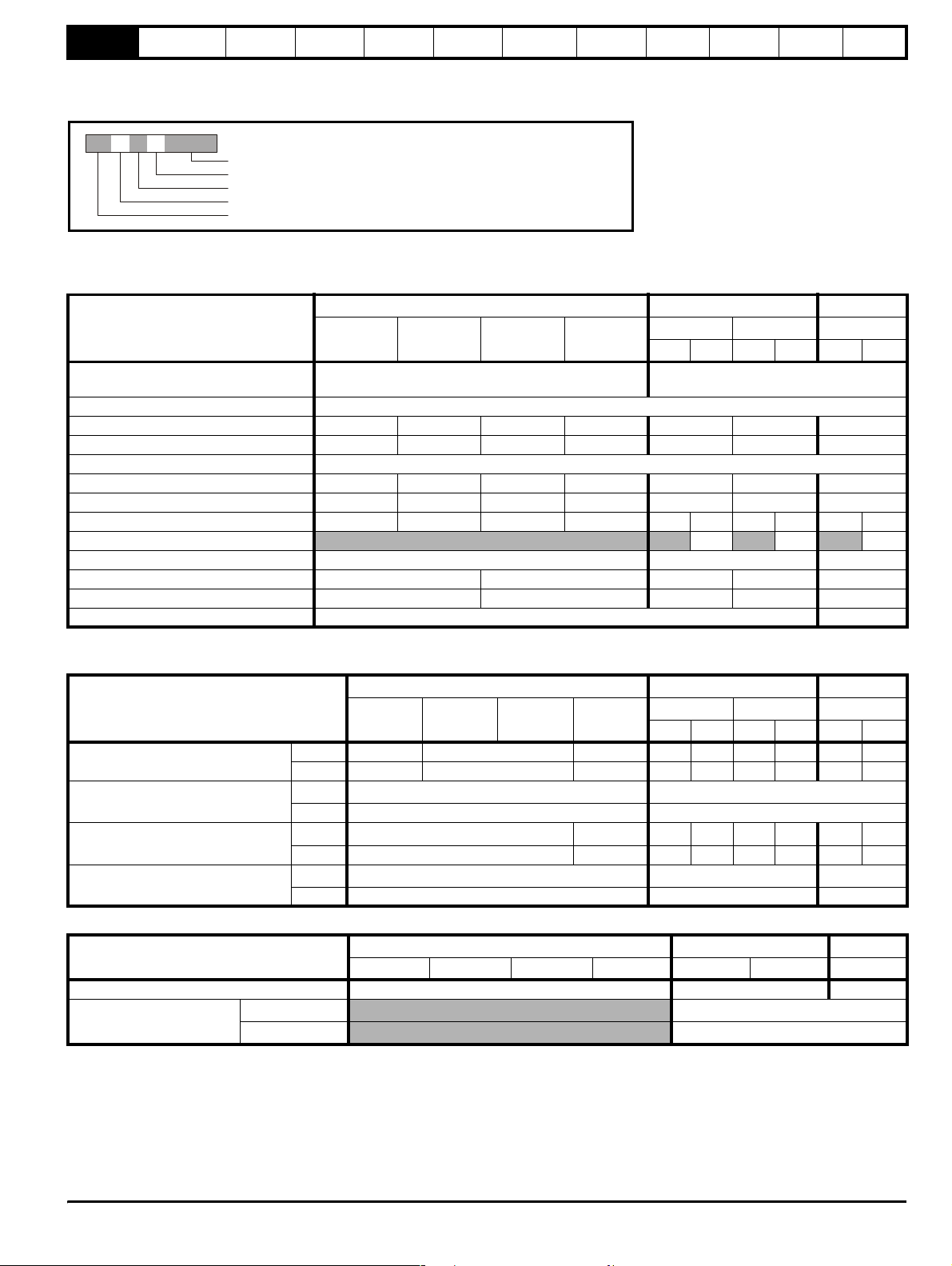
1 Technical data
Figure 1-1 Model code explanation
SL A 1 2 XXXXX
Drive kilowatt rating: 00025 = 0.25kW
Drive voltage rating: 2 = 230V, 4 = 400V
Number of input phases: 1 = 1phase, 3 = 3phase, D = 1 and 3phase
Frame size
Model: Commander SL
1.1 Commander SL 200V units
Table 1-1 Ratings
SLA12 SLBD2 SLCD2
MODEL
00025 00037 00055 00075
AC supply voltage and frequency Single phase 200 to 240V ±10% 48Hz to 62Hz
Input displacement factor (cos∅) >0.97
Nominal motor power (kW) 0.25 0.37 0.55 0.75 1.1 1.5 2.2
Nominal motor power (hp) 0.33 0.50 0.75 1.0 1.5 2.0 3.0
Output voltage and frequency 3 phase, 0 to drive rating (240), 0 to 1500Hz
100% RMS output current (A) 1.7 2.2 3.0 4.0 5.2 7.0 9.6
150% overload current for 60s (A) 2.6 3.3 4.5 6 7.8 10.5 14.4
Typical full load input current (A) 4.3 5.8 8.1 10.5 14.2 6.7 17.4 8.7 23.2 11.9
Maximum continuous input current (A)*
Typical inrush current (A) (<10ms) 17.9 8.9 6.0
Weight (kg) 0.95 1.0 1.3 1.4 2.1
Weight (Ib) 2.1 2.2 2.9 3.1 4.6
Din rail mounting Yes No
* For 3ph input only at 2% negative phase sequence.
Table 1-2 Cables
SLA12 SLBD2 SLCD2
MODEL
Recommended input supply fuse (A)
Control cable
Recommended input cable
Recommended motor cable
IEC 6 10 16 16 10 20 16 25 20
gG 5 10 15 1510201525 20
(mm
(AWG) 20 20
(mm
(AWG) 16 14 121412141012
(mm
(AWG) 16 16 14
00025 00037 00055 00075
2
)
2
)
2
)
≥0.5 ≥0.5
1.0 1.5 2.5 1.5 2.5 1.5 4.0 2.5
1.0 1.0 1.5
00110 00150 00220
1ph 3ph 1ph 3ph 1ph 3ph
Single or 3 phase 200 to 240V ±10% 48Hz
to 62Hz
9.2 12.6 17
00110 00150 00220
1ph 3ph 1ph 3ph 1ph 3ph
Table 1-3 Cooling fan
MODEL
00025 00037 00055 00075 00110 00150 00220
SLA12 SLBD2 SLCD2
Cooling fan fitted No Yes Yes
Air flow
(feet
(m
3
/minute)
3
/minute)
3.8
0.4
Commander SL Technical Data 5
Issue Number: 1 www.controltechniques.com
Page 6
Technical
data
Derating curves
and losses
Drive voltage
levels
DC bus
design
Mechanical
installation
EMC filters
AC line
reactor values
Motor cable
lengths
General
data
I/O
specification
Supply
types
Options
1.2 Commander SL 400V units
Table 1-4 Ratings
MODEL
00037 00055 00075 00110 00150 00220 00300 00400
AC supply voltage and frequency 3 phase 380 to 480V ±10% 48Hz to 62Hz
Input displacement factor (cos∅)>0.97
Nominal motor power (kW) 0.37 0.55 0.75 1.1 1.5 2.2 3.0 4.0
Nominal motor power (hp) 0.5 0.75 1.0 1.5 2.0 3.0 3.0 5.0
Output voltage and frequency 3 phase, 0 to drive rating (480), 0 to 1500Hz
100% RMS output current (A) 1.3 1.7 2.1 2.8 3.8 5.1 7.2 9.0
150% overload current for 60s (A) 2 2.6 3.2 4.2 5.7 7.7 10.8 13.5
Typical full load input current (A) 1.7 2.5 3.1 4 5.2 7.3 9.5 11.9
Maximum continuous input current (A)* 2.5 3.1 3.75 4.6 5.9 9.6 11.2 13.4
Typical inrush current (A) (<10ms) 17.9 11.9
Weight (kg) 1.2 1.3 2.1
Weight (lb) 2.7 2.9 4.6
Din rail mounting Yes No
* For 3phase input only at 2% negative phase sequence.
Table 1-5 Cables
MODEL
Recommended input supply fuse (A)
Control cable
Recommended input cable
Recommended motor cable
IEC 6 10 16
gG 5 10 15
(mm
(AWG) 20 20
(mm
(AWG) 16 14 12
(mm
(AWG) 16 16 14
00037 00055 00075 00110 00150 00220 00300 00400
2
)
2
)
2
)
SLB34 SLC34
SLB34 SLC34
≥0.5 ≥0.5
1.0 1.5 2.5
1.0 1.0 1.5
Table 1-6 Cooling fan
MODEL
00037 00055 00075 00110 00150 00220 00300 00400
SLB34 SLC34
Cooling fan fitted No Yes Yes
Air flow
(feet
(m
3
/minute)
3
/minute)
3.8
0.4
6 Commander SL Technical Data
www.controltechniques.com Issue Number: 1
Page 7
Technical
(
)
data
Derating curves
and losses
Drive voltage
levels
DC bus
design
Mechanical
installation
EMC filters
AC line
reactor values
Motor cable
lengths
General
data
I/O
specification
Supply types Options
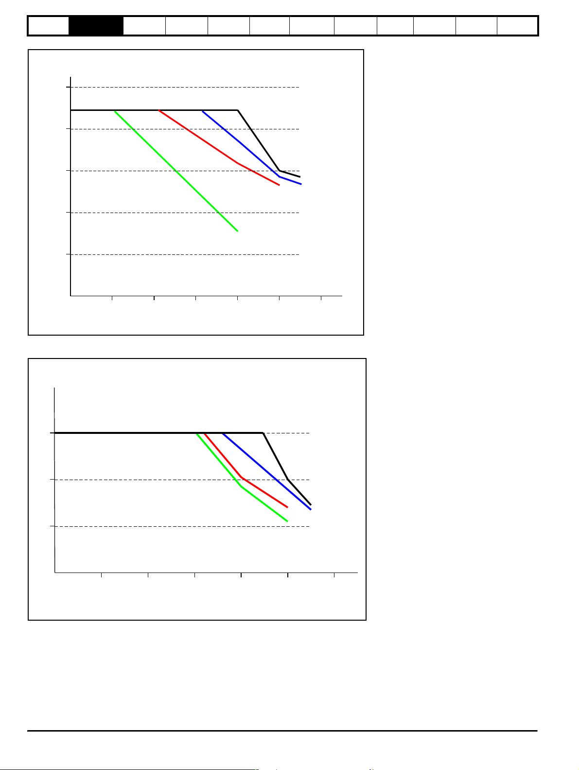
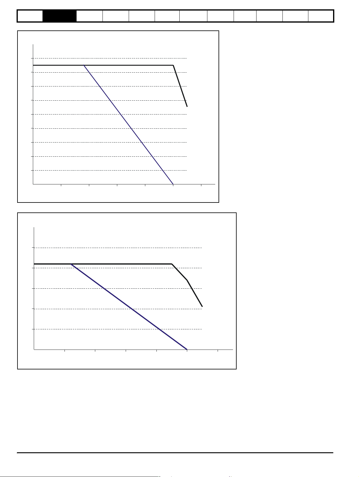
2 Derating curves and losses
The derating curves are based on the results of heatruns that are carried out to measure temperatures of various components and at various key
points within the drive at different switching frequencies, different loads and different ambient temperatures. The key components/points are:
• Heatsink
• Bridge rectifier
•IGBTs
• DC bus capacitors
• Various electrolytic capacitors
• Various resistors
• Various semiconductor components
•etc.
It is not always the heatsink temperature that is the limiting factor for the de-rating curves.
At 3 and 6kHz, the limiting factor tends to be the capacitor temperatures. Operating outside the derating curves will cause some of the capacitors
within the drive to run outside of their maximum operating temperature and this could lead to the drives design lifetime being reduced.
At 12 and 18kHz (18kHz where applicable) the limiting factor tends to be the heatsink temperatures. Operating outside the de-rating curves will cause
the heatsink temperature to increase and may cause the drive to trip on O.ht2.
If the auto-switching frequency change is enabled (Pr 5.35 = 0 [by default]), the drive will automatically decrease the switching frequency when the
heatsink temperature rises above pre-determined levels to reduce the heatsink temperature. When the drive switches down the switching frequency,
the drives display will flash 'hot'.
NOTE
It is important that these de-rating curves are observed.
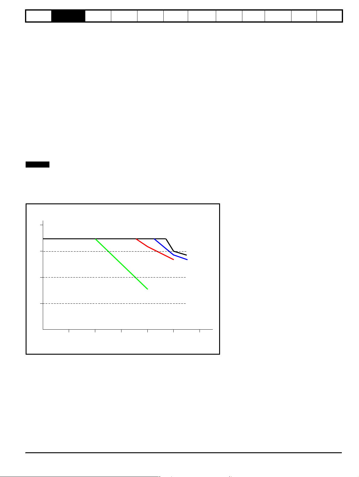
2.1 Size A
2.1.1 Derating curves
Figure 2-1 Commander SL Size A 0.25kW derating curve
Output
current (A)
2.0
1.5
1.0
0.5
3kHz
12kHz
6kHz
18kHz
0
10
20
30
Ambient Temperature
40
50
o
C
60
Commander SL Technical Data 7
Issue Number: 1 www.controltechniques.com
Page 8
Technical
O
O
(°C)
Figure 2-2 Commander SL Size A 0.37kW derating curve
data
Derating curves
and losses
Drive voltage
levels
DC bus
design
Mechanical
installation
utput
current (A)
2.5
2.0
EMC filters
AC line
reactor values
Motor cable
lengths
General
data
I/O
specification
Supply types Options
1.5
1.0
0.5
0
10
20
30
Ambient T emperature (
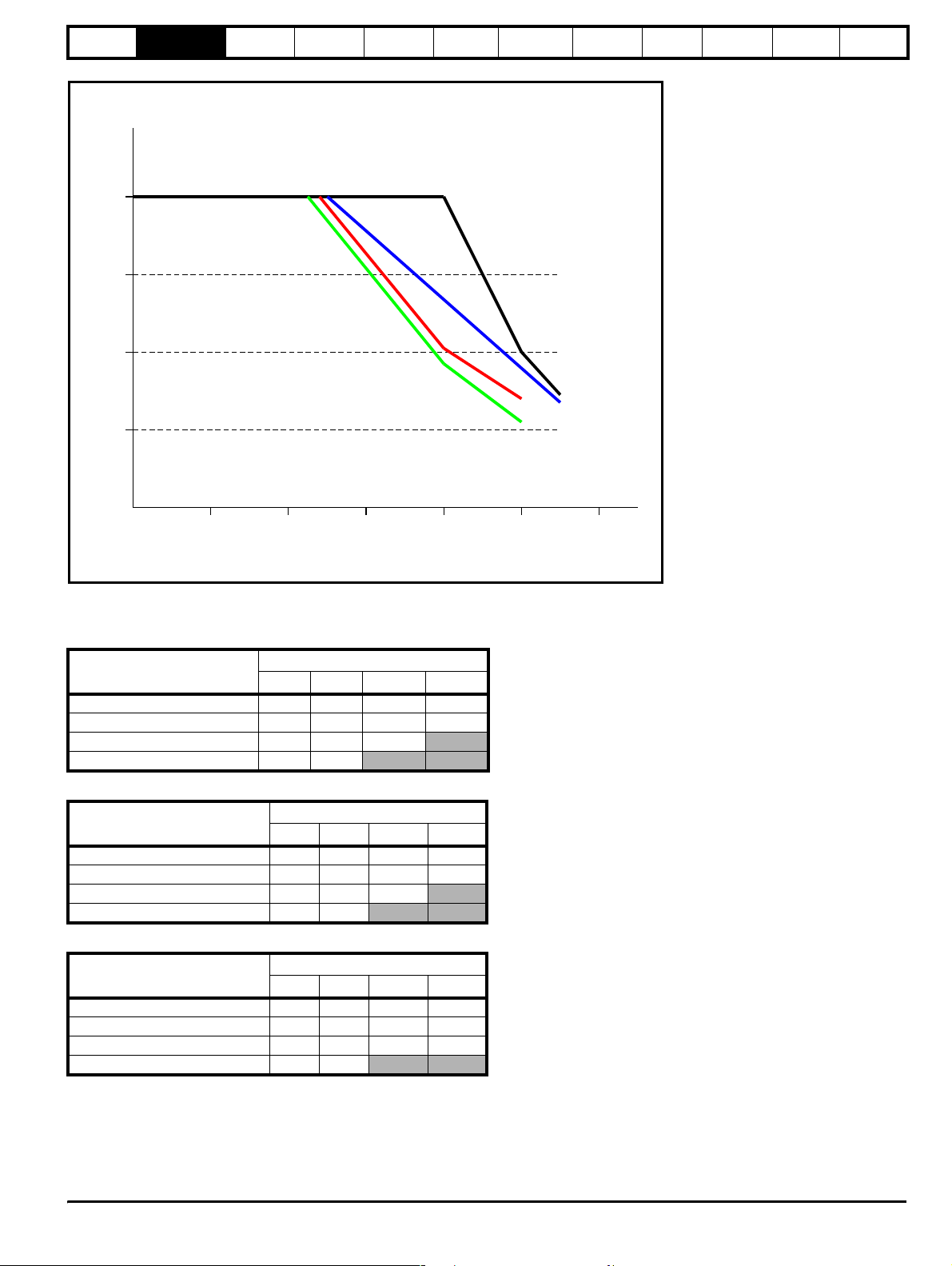
Figure 2-3 Commander SL Size A 0.55kW derating curve
utput
Current (A)
3
18kHz
40
3kHz
50
6kHz
60
12kHz
o
C)
2
1
0
10
3020
40
18kHz
Ambient Temperature
12kHz
3kHz
6kHz
6050
8 Commander SL Technical Data
www.controltechniques.com Issue Number: 1
Page 9
Technical
O
(°C)
Figure 2-4 Commander SL Size A 0.75kW derating curve
data
utput
Current (A)
Derating curves
and losses
Drive voltage
levels
DC bus
design
Mechanical
installation
4
3
2
1
EMC filters
AC line
reactor values
12kHz
18kHz
Motor cable
lengths
3kHz
6kHz
General
data
I/O
specification
Supply types Options
0
10
Ambient T emperature
3020
2.1.2 Drive losses
The following tables indicate the total drive losses at the de-rating curve points.
Table 2-1 Commander SL size A 0.25kW losses
Ambient Temperature (°C)
30 30 32 36 35
40 30 32 38 30
50 29 31 34
55 29 30
Table 2-2 Commander SL size A 0.37kW losses
Ambient Temperature (°C)
30 34 36 38 35
40 34 33 38 30
50 29 31 34
55 29 30
Table 2-3 Commander SL size A 0.55kW losses
Ambient Temperature (°C)
30 42 46 53 61
40 42 43 44 47
50 35 36 37 38
55 31 33
3kHz 6kHz 12kHz 18kHz
3kHz 6kHz 12kHz 18kHz
3kHz 6kHz 12kHz 18kHz
Loss (W)
Loss (W)
Loss (W)
40
6050
Commander SL Technical Data 9
Issue Number: 1 www.controltechniques.com
Page 10
Technical
O
data
Derating curves
and losses
Drive voltage
levels
DC bus
design
Table 2-4 Commander SL size A 0.75kW losses
Ambient Temperature (°C)
3kHz 6kHz 12kHz 18kHz
30 48 50 59 62
40 48 43 44 47
50 35 36 37 38
55 31 33
2.2 Size B
2.2.1 Derating curves
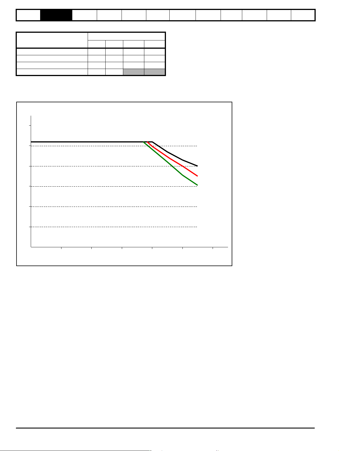
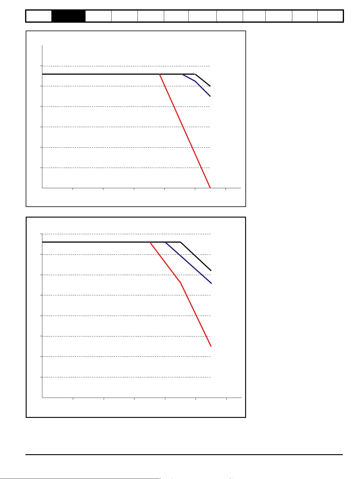
Figure 2-5 Commander SL Size B, 200V, 1.1kW
utput
current (A)
6
5
Mechanical
installation
Loss (W)
EMC filters
AC line
reactor values
Motor cable
lengths
General
data
I/O
specification
Supply types Options
4
3
2
1
0
10 20
30
Ambient Temperature (
40
o
C)
50
3 & 6kHz
12kHz
18kHz
60
10 Commander SL Technical Data
www.controltechniques.com Issue Number: 1
Page 11
Technical
(
)
O
data
Derating curves
and losses
Drive voltage
levels
DC bus
design
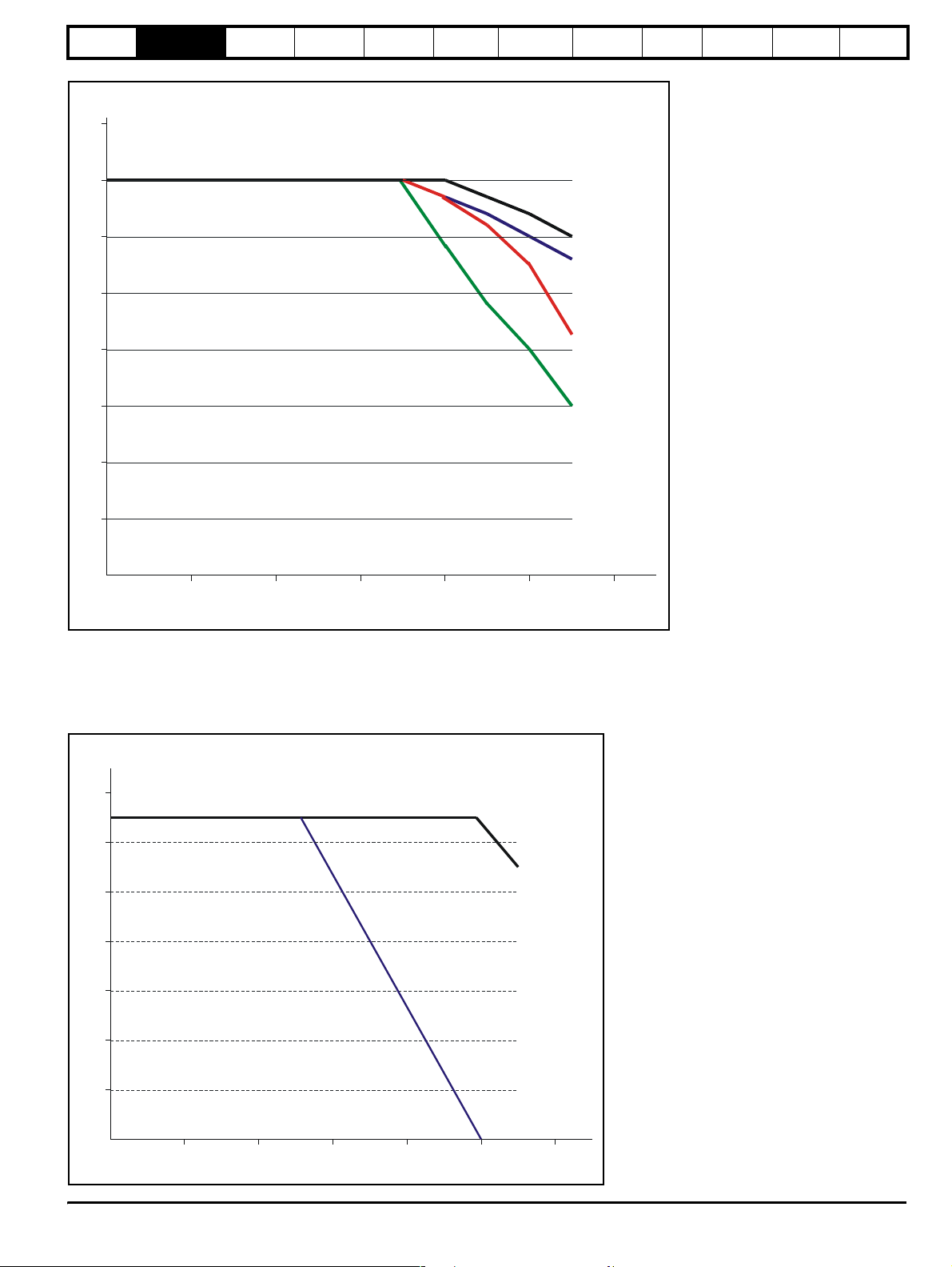
Figure 2-6 Commander SL Size B, 200V, 1.5kW
Output
current (A)
8
7
Mechanical
installation
EMC filters
AC line
reactor values
Motor cable
lengths
General
data
I/O
specification
Supply types Options
6
3kHz
6kHz
5
12kHz
4
3
18kHz
2
1
0
10 20
30
Ambient T emperature
40
o
C
50
60
With the 0.37, 0.55 & 0.75kW drives, no 12kHz derating information is shown on the graphs. This is because the losses at 12kHz is too great to run
the drive continuously. Depending on the duty cycle etc. it is still possible to run the drive at 12kHz but if the heatsink gets too hot, the drive will
automatically switch down the switching frequency to 6kHz. When the drive does this, the display will flash 'hot' to indicate that the drive has
automatically switched down the switching frequency.
Figure 2-7 Commander SL Size B, 400V, 0.37kW
utput
current (A)
1.4
1.2
1.0
0.8
0.6
0.4
0.2
3kHz
6kHz
0
10 20
30
Ambient Temperature (
40
o
C)
50
60
Commander SL Technical Data 11
Issue Number: 1 www.controltechniques.com
Page 12
Technical
(
)
O
(
)
data
Derating curves
and losses
Drive voltage
levels
DC bus
design
Figure 2-8 Commander SL Size B, 400V, 0.55kW
Output
current (A)
1.8
1.6
1.4
Mechanical
installation
EMC filters
AC line
reactor values
Motor cable
lengths
General
data
I/O
specification
Supply types Options
1.2
1.0
0.8
0.6
0.4
0.2
0
10 20
30
Ambient T emper ature
Figure 2-9 Commander SL Size B, 400V, 0.75kW
utput
current (A)
2.5
2.0
3kHz
6kHz
40
o
C
50
60
1.5
1.0
0.5
3kHz
6kHz
0
10 20
30
Ambient Temperature
40
o
C
50
60
12 Commander SL Technical Data
www.controltechniques.com Issue Number: 1
Page 13
Technical
(
)
O
(
)
data
Derating curves
and losses
Drive voltage
levels
DC bus
design
Figure 2-10 Commander SL Size B, 400V, 1.1kW
Output
current (A)
3.0
Mechanical
installation
EMC filters
AC line
reactor values
Motor cable
lengths
General
data
I/O
specification
Supply types Options
2.5
2.0
1.5
1.0
0.5
0
10 20
30
Ambient T emperature
Figure 2-11 Commander SL Size B, 400V, 1.5kW
utput
current (A)
4.0
3.5
3kHz
6kHz
12kHz
40
o
C
50
60
3.0
3kHz
6kHz
2.5
2.0
1.5
12kHz
1.0
0.5
0
10 20
30
Ambient T emperature
40
o
C
50
60
Commander SL Technical Data 13
Issue Number: 1 www.controltechniques.com
Page 14

Technical
data
Derating curves
and losses
Drive voltage
levels
DC bus
design
Mechanical
installation
EMC filters
reactor values
2.2.2 Drive losses
The following tables indicate the total drive losses at the de-rating curve points.
Table 2-5 Commander SL Size B, 200V, 1.1kW
Ambient Temperature (°C)
3kHz 6kHz 12kHz 18kHz
30 58 63 73 84
40 58 63 70 78
50 51 55 60 62
55 48 51 54 57
Table 2-6 Commander SL Size B, 200V, 1.5kW
Ambient Temperature (°C)
3kHz 6kHz 12kHz 18kHz
30 72 79 85 92
40 72 76 82 80
50 66 69 71 59
55 63 65 57 50
Table 2-7 Commander SL Size B, 400V, 0.37kW
Ambient Temperature (°C)
3kHz 6kHz 12kHz
30 24 27
40 24 21
50 24
55 22
Loss (W)
Loss (W)
Loss (W)
AC line
Motor cable
lengths
General
data
I/O
specification
Supply types Options
Table 2-8 Commander SL Size B, 400V, 0.55kW
Ambient Temperature (°C)
3kHz 6kHz 12kHz
Loss (W)
30 27 26
40 27 21
50 27
55 22
Table 2-9 Commander SL Size B, 400V, 0.75kW
Ambient Temperature (°C)
3kHz 6kHz 12kHz
Loss (W)
30 31 27
40 31 21
50 26
55 22
Table 2-10 Commander SL Size B, 400V, 1.1kW
Ambient Temperature (°C)
3kHz 6kHz 12kHz
Loss (W)
30 43 51 68
40 43 51 62
50 43 49 35
55 40 44
Table 2-11 Commander SL Size B, 400V, 1.5kW
Ambient Temperature (°C)
3kHz 6kHz 12kHz
Loss (W)
30 53 65 87
40 53 65 76
50 49 55 55
55 46 51 45
14 Commander SL Technical Data
www.controltechniques.com Issue Number: 1
Page 15

Technical
O
(
)
(
)
data
Derating curves
and losses
Drive voltage
levels
DC bus
design
2.3 Size C
2.3.1 Derating curves
Table 2-12 Commander SL Size C, 200V, 2.2kW
utput
current (A)
10.0
9.0
Mechanical
installation
EMC filters
AC line
reactor values
Motor cable
lengths
General
data
I/O
specification
Supply types Options
8.0
7.0
6.0
5.0
4.0
3.0
2.0
1.0
0
10 20
30
Ambient Temperature
Table 2-13 Commander SL Size C, 400V, 2.2kW
Output
current (A)
6.0
3kHz
6 & 12kHz
18kHz
40
o
C
50
60
5.0
4.0
3 & 6kHz
3.0
2.0
12kHz
1.0
0
10 20
30
Ambient T emperature
40
o
C
50
60
Commander SL Technical Data 15
Issue Number: 1 www.controltechniques.com
Page 16

Technical
(
)
data
Derating curves
and losses
Drive voltage
levels
DC bus
design
Table 2-14 Commander SL Size C, 400V, 3.0kW
Output
current (A)
8.0
7.0
6.0
Mechanical
installation
EMC filters
AC line
reactor values
Motor cable
lengths
General
data
I/O
specification
Supply types Options
5.0
4.0
3.0
2.0
1.0
0
10 20
30
Ambient Temperature
Table 2-15 Commander SL Size C, 400V, 4.0kW
9.0
8.0
7.0
6.0
3kHz
6kHz
12kHz
40
o
C
50
60
5.0
4.0
3.0
2.0
1.0
3kHz
6kHz
12kHz
0
10 20
30
Ambient Temperature (
40
o
C)
50
60
16 Commander SL Technical Data
www.controltechniques.com Issue Number: 1
Page 17

Technical
data
Derating curves
and losses
Drive voltage
levels
DC bus
design
2.3.2 Drive losses
Table 2-16 Commander SL Size C, 200V, 2.2kW
Ambient Temperature (°C)
30 93 107 133 158
40 93 107 133 158
50 84 93 115 133
55 80 88 109 111
Table 2-17 Commander SL Size C, 400V, 2.2kW
Ambient Temperature (°C)
30 78 108 118
40 78 108 101
50 78 108 88
55 78 108 60
Table 2-18 Commander SL Size C, 400V, 3.0kW
Ambient Temperature (°C)
30 91 117 93
40 91 117 78
50 91 94 62
55 70 77 47
3kHz 6kHz 12kHz 18kHz
Loss (W)
3kHz 6kHz 12kHz
Loss (W)
3kHz 6kHz 12kHz
Mechanical
installation
Loss (W)
EMC filters
AC line
reactor values
Motor cable
lengths
General
data
I/O
specification
Supply types Options
Table 2-19 Commander SL Size C, 400V, 4.0kW
Ambient Temperature (°C)
Loss (W)
3kHz 6kHz 12kHz
30 116 149 99
40 116 132 84
50 96 100 69
55 75 83 54
Commander SL Technical Data 17
Issue Number: 1 www.controltechniques.com
Page 18

Technical
data
Derating curves
and losses
Drive voltage
levels
DC bus
design
Mechanical
installation
EMC filters
AC line
reactor values
Motor cable
lengths
General
data
I/O
specification
Supply types Options
3 Drive voltage levels
Condition 200V drives 400V drives
OV trip level 415 Vdc 830 Vdc
Rated upper level (AC mains +10% x 1.4142) 373 Vdc 747 Vdc
Rated lower level (AC mains -10% x 1.4142) 255 Vdc 484 Vdc
*UV reset level 215 Vdc 425 Vdc
UV trip level 175 Vdc 330 Vdc
Standard ramp voltage 375 Vdc
* These are the absolute minimum DC voltages that the drive can be supplied with. If the drive is not supplied with at least this voltage, it will not reset
out of a UU trip at power up.
Output frequency: 0 to 1500Hz
Output voltage: 3 phase, 0 to drive rating (240 or 480Vac maximum set by Pr 08).
3.1 Input voltage
3.1.1 Single phase
200V to 240V ±10%
48Hz to 62Hz
3.1.2 Three phase 200V
200V to 240V ±10%
48Hz to 62Hz
Phase imbalance 3% (between phases) or 2% negative phase sequence (IEC 146-1-1 Immunity class C)
3.1.3 Three phase 400V
380V to 480V ±10%
48Hz to 62Hz
Phase imbalance 3% (between phases) or 2% negative phase sequence (IEC 146-1-1 Immunity class C)
It is possible to run the drives on lower supply voltages than those specified above (up to -20%) but only with de-rating of the product.
On products without a DC bus choke (up to 4kW), the maximum supply capacity connected to the drive without using external line chokes will be 5kA
short circuit current.
Eur: 750 Vdc
USA: 775 Vdc
18 Commander SL Technical Data
www.controltechniques.com Issue Number: 1
Page 19

Technical
data
Derating curves
and losses
Drive voltage
levels
DC bus
design
Mechanical
installation
EMC filters
AC line
reactor values
4 DC bus design
Table 4-1 Commander SL 200V units DC bus data
Model
DC Bus Capacitance
µF
Inrush resistance at 25
Ω
SLA1200025 330 22 17
SLA1200037 390 22 17
SLA1200055 660 22 17
SLA1200075 780 22 17
SLBD200110 940 13.6 27.4
SLBD200150 1410 13.6 27.4
SLCD200220 1880 20.4 18.3
Table 4-2 Commander SL 400V units DC bus data
Model
DC Bus Capacitance
µF
Inrush resistance at 25
Ω
SLB3400037 165 44 17
SLB3400055 165 44 17
SLB3400075 165 44 17
SLB3400110 195 44 17
SLB3400150 235 44 17
SLC3400220 470 66 11.3
SLC3400300 470 66 11.3
SLC3400400 470 66 11.3
o
Peak inrush current
C
o
Peak inrush current
C
A
A
Motor cable
lengths
General
data
I/O
specification
Supply
types
Options
Commander SL Technical Data 19
Issue Number: 1 www.controltechniques.com
Page 20

Technical
data
Derating curves
and losses
Drive voltage
levels
DC bus
design
Mechanical
installation
5 Mechanical installation
5.1 Mechanical dimensions
Figure 5-1 Size A mounting dimensions
E
D
C
ABH
EMC filters
G
AC line
reactor values
Motor cable
lengths
F
General
data
I/O
specification
Supply
types
Options
Dimension mm in
A
B
C
F
D
E
F
G
H
Holesize 4 x M4
NOTE
If DIN rail mounting is used in an installation where the drive is to be subjected to shock or vibration, it is recommended that the bottom mounting
screws are used to secure the drive to the back plate. If the installation is going to be subjected to heavy shock and vibration, then it is recommended
that the drive is surface mounted rather than DIN rail mounted
N
140
154
11
64
75
145
104
143
5.51
6.06
0.43
2.52
2.95
5.7
4.1
5.63
20 Commander SL Technical Data
www.controltechniques.com Issue Number: 1
Page 21

Technical
E
Figure 5-2 Size B mounting dimensions
data
Derating curves
and losses
Drive voltage
levels
D
DC bus
design
C
Mechanical
installation
B
A
EMC filters
I
H
AC line
reactor values
Motor cable
lengths
General
G
data
I/O
specification
Supply
types
Options
F
Dimension mm in
A
B
C
D
G
E
190
205
10.9
65.9
F
G
H
I
Holesize 4 x M4
NOTE
If DIN rail mounting is used in an installation where the drive is to be subjected to shock or vibration, it is recommended that the bottom mounting
screws are used to secure the drive to the back plate. If the installation is going to be subjected to heavy shock and vibration, then it is recommended
that the drive is surface mounted rather than DIN rail mounted
N
156
155.5
194
85
77
7.48
8.07
0.43
2.6
3.35
3
6.15
6.1
7.64
Commander SL Technical Data 21
Issue Number: 1 www.controltechniques.com
Page 22

Technical
Figure 5-3 Size C mounting dimensions
data
Derating curves
and losses
Drive voltage
levels
E
D
DC bus
design
C
Mechanical
installation
BH
A
EMC filters
AC line
reactor values
Motor cable
lengths
General
data
G
I/O
specification
Supply
types
Options
Size C is not DIN rail mountable.
F
Dimension mm in
A
B
C
D
G
E
F
G
H
Holesize 4 x M4
240
258
10.4
81.1
100
91.9
173
244
9.45
10.16
0.41
3.2
3.94
3.62
6.8
9.61
22 Commander SL Technical Data
www.controltechniques.com Issue Number: 1
Page 23

Technical
data
Derating curves
and losses
Drive voltage
levels
DC bus
design
Mechanical
installation
5.2 Minimum mounting clearances
Figure 5-4 Minimum mounting clearances
EMC filters
AC line
reactor values
Motor cable
lengths
General
data
I/O
specification
Supply
types
Options
ABCA
Drive size
A
B (≤0.75kW) 10* 0.39*
B (≥1.1kW) 0 0
ABC
mm in mm in mm in
00
10 0.39
C
100 3.94
C 50* 1.97*
*This is the minimum spacing between drives measured at the base of the drives where it is mounted against a back plate/flat surface.
Commander SL Technical Data 23
Issue Number: 1 www.controltechniques.com
Page 24

Technical
data
Derating curves
and losses
Drive voltage
levels
DC bus
design
Mechanical
installation
6 EMC filters
EMC filters are available as optional extra parts where required.
Table 6-1 EMC filters
Number
Used with
phases
SLA1200025
and
SLA1200037
SLA1200055
and
SLA1200075
SLBD200110 to
SLBD200150
SLBD200110 to
SLBD200150
SLB3400037 to
SLB3400150
SLCD200220 1
SLCD200220 3
SLC3400220 to
SLC3400400
of
1
1
1
3
3
3
Filter part number Filter type Mounting
CT Schaffner Standard Low leakage Footprint Side
4200-6122 FS6512-12-07 Y
4200-6123 FS6512-12-07-LL
4200-6122 FS6512-12-07 Y
4200-6123 FS6512-12-07-LL
4200-6212 FS6513-20-07 Y
4200-6214 FS6513-20-07-LL
4200-6213 FS6513-10-07 Y
4200-6215 FS6513-10-07-LL
4200-6213 FS6513-10-07 Y
4200-6215 FS6513-10-07-LL
4200-6310 FS6514-24-07 Y
4200-6312 FS6514-24-07-LL
4200-6311 FS6514-14-07 Y
4200-6217 FS6514-14-07-LL
4200-6311 FS6514-14-07 Y
4200-6217 FS6514-14-07-LL
EMC filters
AC line
reactor values
YYY10
YYY30
YYY10
YYY50
YYY20
YYY10
YYY50
YYY20
Motor cable
lengths
General
data
I/O
specification
Supply
types
Options
Max motor
cable length (m)
YY75
YY75
Y Y 100
Y Y 100
Y Y 100
Y Y 100
Y Y 100
Y Y 100
6.1 Filter data
Table 6-2 EMC filter data
Number
Used with
SLA1200025
to
SLA1200075
SLBD200110
to
SLBD200150
SLBD200110
to
SLBD200150
SLB3400037
to
SLB3400150
SLCD200220 1
SLCD200220 3
SLC3400220
to
SLC3400400
of
phases
1
1
3
3
3
Worst
case
leakage
current
Filter terminal
tightening
torque
Filter
current
rating
Filter part number
Power
losses
at rated
current
IP
rating
Weight
Operational
leakage
current
CT Schaffner W Kg lb mA mA Nm lb ft A
4200-6122 FS6512-12-07 4.1 20 0.42 0.9 25.7 49.5 0.8 0.6 12
4200-6123 FS6512-12-07-LL 6.7 20 0.44 1.0 2.5 5 0.8 0.6 12
4200-6212 FS6513-20-07 11.2 20 0.57 1.3 25.7 50 0.8 0.6 20
4200-6214 FS6513-20-07-LL 12.8 20 0.64 1.4 3.6 7 0.8 0.6 20
4200-6213 FS6513-10-07 7.5 20 0.63 1.4 40 137.2 0.8 0.6 10
4200-6215 FS6513-10-07-LL 7.5 20 0.63 1.4 3 18.3 0.8 0.6 10
4200-6213 FS6513-10-07 7.5 20 0.63 1.4 40 137.2 0.8 0.6 10
4200-6215 FS6513-10-07-LL 7.5 20 0.63 1.4 3 18.3 0.8 0.6 10
4200-6310 FS6514-24-07 16.2 20 0.84 1.9 25.7 50 0.8 0.6 24
4200-6312 FS6514-24-07-LL 18.5 20 0.91 2.0 3.6 7 0.8 0.6 24
4200-6311 FS6514-14-07 11.8 20 0.75 1.7 40 137.2 0.8 0.6 14
4200-6217 FS6514-14-07-LL 11.8 20 0.74 1.6 3 18.3 0.8 0.6 14
4200-6311 FS6514-14-07 11.8 20 0.75 1.7 40 137.2 0.8 0.6 14
4200-6217 FS6514-14-07-LL 11.8 20 0.74 1.6 3 18.3 0.8 0.6 14
24 Commander SL Technical Data
www.controltechniques.com Issue Number: 1
Page 25

Technical
data
Derating curves
and losses
Drive voltage
6.2 Conformity
Table 6-3 Conformity
Used with
SLA1200025 and
SLA1200037
SLA1200055 and
SLA1200075
SLBD200110 to
SLBD200150
SLBD200110 to
SLBD200150
SLB3400037 to
SLB3400150
SLCD200220 1
SLCD200220 3
SLC3400220 to
SLC3400400
* Cable capacitance, Cy = 47nF
Number
Phases
levels
Of
1
1
1
3
3
3
DC bus
design
Motor
cable length
(m)
Mechanical
installation
EMC filters
AC line
reactor values
Standard Low leakage
3kHz 6kHz 12kHz 18kHz 3kHz 6kHz 12kHz 18kHz
Motor cable
lengths
General
data
specification
Filter and switching frequency
I/O
Supply
types
5RRRR
10 RRRRRI I I
20 R R I I
30 I I I I
50 I I I I
75 I
5RRRR
10 RRRRRI I I
20 R R I I
30 I I I I
50 I I I I
75 I
10 RI I I
20 R I I I
100 I
2RRII
5RRRI
10 R I I I R I I I
15 R R I I R I I I
20 R I I III
50 I
100 R I I I
2RRRR
5RRRR
10 R R I I R I I I
15 R R I I I I I
20 R I I I I I
50
100 I
2RRRR
5RRRR
10 R R R R R*
15 R R R R
20 R R R R
50 I I I I
75 I I I I
100 I
2RRRR
5RRRR
10 R R R R I I I I
15 R R R R I I I I
20 R R R R I I I
50 R R I I I
75 I I I I
100 I I I I
2RRRR
5RRRR
10 R R R I I I I I
15 R R R I I I I
20 R R R I I I
50 R I I I
75 I I I
100 I
Options
Commander SL Technical Data 25
Issue Number: 1 www.controltechniques.com
Page 26

Technical
data
Derating curves
and losses
Drive voltage
levels
DC bus
design
Mechanical
installation
EMC filters
AC line
reactor values
Motor cable
lengths
General
data
I/O
specification
Supply
types
Options
Key to Table 6-3 Conformity
The requirements are listed in descending order of severity, so that if a particular requirement is met then all requirements listed after it are also met.
Standard Description Frequency range Limits Application
R
I
E2U
E2R
EN 61000-6-3
(previously EN
50081-1)
EN 61800-3
IEC 61800-3
EN 61000-6-4
(previously EN
50081-2)
EN 61800-3
IEC 61800-3
EN 61800-3
IEC 61800-3
EN 61800-3
IEC 61800-3
Generic emission
standard for the
residential commercial
and light - industrial
environment
Product standard for
adjustable speed power
drive systems
Generic emission
standard for the
industrial environment
Product standard for
adjustable speed power
drive systems
Product standard for
adjustable speed power
drive systems
Product standard for
adjustable speed power
drive systems
0.15 - 0.5MHz
limits decrease linearly
with log frequency
5 - 30MHz
Requirements for the first environment
0.15 - 0.5MHz
0.5 -30MHz
Requirements for the first environment
Requirements for the second environment with unrestricted
Requirements for the second environment with restricted
66-56dBµV quasi peak
56-46dBµV average
56dBµV quasi peak
46dBµV average
60dBµV quasi peak
50dBµV average
1
, with unrestricted
distribution
79dBµV quasi peak
66dBµV average
73dBµV quasi peak
60dBµV average
1
with restricted
distribution
2
distribution
distribution
2
AC supply
lines0.5 - 5MHz
AC supply
lines
Operation in this condition is not recommended
1 The first environment is one where the low voltage supply network also supplies domestic premises
2 When distribution is restricted, drives are available only to installers with EMC competence
Key (shown in decreasing order of permitted emission level):
E2R EN 61800-3 second environment, restricted distribution (Additional measures may be required to prevent interference)
E2U EN 61800-3 second environment, unrestricted distribution
I Industrial generic standard EN 50081-2 (EN 61000-6-4)
EN 61800-3 first environment restricted distribution (The following caution is required by EN 61800-3)
This is a product of the restricted distribution class according to IEC 61800-3. In a domestic environment this product may cause radio
interference in which case the user may be required to take adequate measures.
CAUTION
R Residential generic standard EN 50081-1 (EN 61000-6- 3)
EN 61800-3 first environment unrestricted distribution
EN 61800-3 defines the following:
• The first environment is one that includes domestic premises. It also includes establishments directly connected without inter mediate
transformers to a low-voltage power supply network which supplies buildings used for domestic purposes.
• The second environment is one that includes all establishments other than those directly connected to a low-voltage power supply network which
supplies buildings used for domestic purposes.
Restricted distribution is defined as a mode of sales distribution in which the manufacturer restricts the supply of equipment to suppliers,
customers or users who separately or jointly have technical competence in the EMC requirements of the application of drives.
NOTE
N
Where the drive is incorporated into a system with rated input current exceeding 100A, the higher emission limits of EN 61800-3 for the second
environment are applicable, and no filter is then required.
26 Commander SL Technical Data
www.controltechniques.com Issue Number: 1
Page 27

Technical
A
g
data
Derating curves
and losses
Drive voltage
levels
Table 6-4 EMC filter dimensions
Y
DC bus
design
Mechanical
installation
EMC filters
AC line
reactor values
Motor cable
lengths
General
data
Z
I/O
specification
Supply
types
Options
CT part
no.
4200-6122
4200-6123
4200-6212
4200-6214
4200-6213
4200-6215
4200-6310
4200-6312
4200-6311
4200-6217
W
D
Schaffner
part no.
FS6512-
12-07
FS6512-
12-07-LL
FS6513-
20-07
FS651320-07-LL
FS6513-
10-07
FS651310-07-LL
FS6514-
24-07
FS651424-07-LL
FS6514-
14-07
FS651414-07-LL
C
X
X
V
U
F
H
B
Z
E
V: Ground stud:
X:Threaded holes for footprint mounting of the drive
∅
Y: Footprint mounting holes
Z: Bookcase mountin
holes
∅
ABCDEFHUVWXYZ
155mm
(6.10in)
155mm
(6.10in)
209mm
(8.22in)
209mm
(8.22in)
209mm
(8.22in)
209mm
(8.22in)
260mm
(10.23in)
260mm
(10.23in)
260mm
(10.23in)
260mm
(10.23in)
183.5mm
(7.22in)
183.5mm
(7.22in)
237.7mm
(9.35in)
237.7mm
(9.35in)
237.7mm
(9.35in)
237.7mm
(9.35in)
288.5mm
(11.35in)
288.5mm
(11.35in)
288.5mm
(11.35in)
288.5mm
(11.35in)
45mm
(1.77in)
45mm
(1.77in)
50mm
(1.96in)
50mm
(1.96in)
50mm
(1.96in)
50mm
(1.96in)
65mm
(2.55in)
65mm
(2.55in)
65mm
(2.55in)
65mm
(2.55in)
40mm
(1.57in)
40mm
(1.57in)
40mm
(1.57in)
40mm
(1.57in)
40mm
(1.57in)
40mm
(1.57in)
45mm
(1.77in)
45mm
(1.77in)
45mm
(1.77in)
45mm
(1.77in)
20mm
(0.78in)
20mm
(0.78in)
20mm
(0.78in)
20mm
(0.78in)
20mm
(0.78in)
20mm
(0.78in)
20mm
(0.78in)
20mm
(0.78in)
20mm
(0.78in)
20mm
(0.78in)
144mm
(5.66in)
144mm
(5.66in)
193.5mm
(7.61in)
193.5mm
(7.61in)
193.5mm
(7.61in)
193.5mm
(7.61in)
244mm
(9.60in)
244mm
(9.60in)
244mm
(9.60in)
244mm
(9.60in)
203mm
(7.99in)
203mm
(7.99in)
257.2mm
(10.12in)
257.2mm
(10.12in)
257.2mm
(10.12in)
257.2mm
(10.12in)
308mm
(12.12in)12AWG
308mm
(12.12in)12AWG
308mm
(12.12in)16AWG
308mm
(12.12in)16AWG
16
AWG
16
AWG
14
AWG
14
AWG
14
AWG
14
AWG
M4
M4
M4
M4
M4
M4
M4
M4
M4
M4
75mm
(2.95in)
75mm
(2.95in)
80mm
(3.15in)
80mm
(3.15in)
80mm
(3.15in)
80mm
(3.15in)
94mm
(3.70in)
94mm
(3.70in)
94mm
(3.70in)
94mm
(3.70in)
M4
M4
M4
M4
M4
M4
M4
M4
M4
M4
8.7mm
(0.34in)
8.7mm
(0.34in)
8.7mm
(0.34in)
8.7mm
(0.34in)
8.7mm
(0.34in)
8.7mm
(0.34in)
8.7mm
(0.34in)
8.7mm
(0.34in)
8.7mm
(0.34in)
8.7mm
(0.34in)
4.5mm
(0.17in)
4.5mm
(0.17in)
4.5mm
(0.17in)
4.5mm
(0.17in)
4.5mm
(0.17in)
4.5mm
(0.17in)
4.5mm
(0.17in)
4.5mm
(0.17in)
4.5mm
(0.17in)
4.5mm
(0.17in)
Commander SL Technical Data 27
Issue Number: 1 www.controltechniques.com
Page 28

Technical
data
Derating curves
and losses
Drive voltage
levels
DC bus
design
Mechanical
installation
EMC filters
AC line
reactor values
Motor cable
lengths
General
data
specification
7 AC line reactor values
Table 7-1 AC line reactor values
Continuous
rms current
Drives used with
SLA1200025
SLA1200037
Reactor part
number
Input
phases
Inductance
mH A A Kg L D H
4402-0224 1 2.25 6.5 13 0.8 72 65 90
SLA1200055
4402-0225 1 1.0 15.1 30.2 1.1 82 75 100SLA1200075
SLBD200110
SLBD200150
SLCD200220
SLBD200110
SLBD200150
4402-0226 1 0.5 26.2 52.4 1.5 82 90 105
4402-0228 3 1.0 15.4 47.4 3.8 150 90 150
SLCD200220 4402-0229 3 0.4 24.6 49.2 3.8 150 90 150
SLB3400037
SLB3400055
SLB3400075
4402-0227 3 2.0 7.9 15.8 3.5 150 90 150
SLB3400110
SLB3400150
SLC3400220
4402-0228 3 1.0 15.4 47.4 3.8 150 90 150SLC3400300
SLC3400400
Peak
current
Weight Dimensions
I/O
Supply
types
Options
7.1 Line reactors
Input line reactors reduce the risk of damage to the drive resulting from poor phase balance or severe disturbances on the supply network.
Where line reactors are to be used, reactance values of approximately 2% are recommended. Higher values may be used if necessary, but may result
in a loss of drive output voltage because of voltage drop. This may reduce torque at high speed.
For all drive ratings, 2% line reactors permit drives to be used with a supply imbalance of up to 3.5% negative phase sequence (equivalent to 5%
voltage imbalance between phases).
A line reactor should be connected in each phase of the supply. Each drive should have its own line reactor . Three individual reactors or a single three
phase reactor can be used. Single phase drives only require one single phase line reactor.
Severe disturbances may be caused by the following factors:
• Power factor correction equipment connected close to the drive
• Large DC drives having no or inadequate line reactors connected to the supply
• Direct-on-line started motor(s) connected to the supply such that when any of these motors are started, the voltage dip exceeds 20%.
• Supply capacity exceeds 200kVA
• Fault current exceeds 5kA
Such disturbances may cause excessive peak currents to flow in the input power circuit of the drive. This may cause nuisance tripping and in extreme
cases, failure of the drive.
Low power drives may also be susceptible to disturbance when connected to supplies with high rated capacity.
NOTE
N
RFI filters (for EMC purposes) do not give adequate protection against these conditions.
7.2 Reactor current ratings
Continuous current:
Not less than the continuous input current rating of the drive.
Repetitive peak current rating:
Not less than twice the continuous input current rating of the drive.
Voltage fluctuation (Flicker) standard EN61000-3-3 (IEC61000-3-3)
Those models that fall within the scope of EN61000-3-3, as stated in the declaration of Conformity, conform to the requirements for manual switching,
i.e. the voltage dip caused when a drive at room temperature is switched on is within the permitted limits.
The drive does not of itself cause periodic voltage fluctuation in normal operation. The installer must ensure that the control of the drive is such that
periodic fluctuations in supply current do not infringe the flicker requirements where applicable. Note that large periodic load fluctuations in the
frequency range of between 1Hz and 30Hz are particularly inclined to cause irritating lighting flicker and are subject to stringent limits under
EN61000-3-3.
28 Commander SL Technical Data
www.controltechniques.com Issue Number: 1
Page 29

Technical
A
G
data
Derating curves
and losses
Drive voltage
levels
DC bus
design
Mechanical
installation
EMC filters
AC line
reactor values
Motor cable
lengths
General
data
I/O
specification
Supply
types
Options
7.3 Input line reactors for harmonics standards EN61000-3-2 and IEC61000-3-2
The following input line reactors allow the Commander SL 0.25 - 0.55kW drives to conform to harmonic standards EN61000-3-2 and IEC61000-3-2.
Table 7-2 Input line reactors for harmonics standards EN61000-3-2 and IEC61000-3-2
Drive
Reactor part
number
Drive power
de-rating
Input
power
Inductance
WmH
Continuous
rms current
SLA12200025 4400-0239 None 374 4.5 2.4
SLA12200037 4400-0238 None 553 9.75 3.2
SLA12200055 4400-0237 18% 715 16.25 4.5
EN61000-3-2 and IEC61000-3-2 applies to equipment with a supply voltage of 230VAC and a line current up to 16A, single or three phase.
Professional equipment with rated input power exceeding 1kW has no limits - this applies to the 0.75kW drive.
Further information on EN61000-3-2 and IEC61000-3-2 is included on the EMC data sheets available from your local Control Techniques drive centre
or distributor.
7.4 Voltage fluctuation (Flicker) standard EN61000-3-3 (IEC61000-3-3)
Those models which fall within the scope of EN61000-3-3, as stated in the Declaration of Conformity, conform to the requirements for manual
switching, i.e. the voltage dip caused when a drive at room temperature is switched on is within the permitted limits.
The drive does not of itself cause periodic voltage fluctuation in normal operation. The installer must ensure that the control of the drive is such that
periodic fluctuations in supply current do not infringe the flicker requirements where applicable. Note that large periodic load fluctuations in the
frequency range of between 1Hz and 30Hz are particularly inclined to cause irritating lighting flicker and are subject to stringent limits under
EN61000-3-3.
Figure 7-1 Input line reactor 4402-0224, 4402-0225 and 4402-0226
round
terminal
C
B
D
E
Table 7-3 Dimensions
Part No
ABCDEFixing hole
Dimensions
4402-0224 90mm (3.54in) 72mm (2.84in) 44.5mm (1.75in) 35mm (1.38in) 65mm (2.56in)
4402-0226 105mm (4.13in) 53mm (2.09in) 90mm (3.54in)
82mm (3.23in) 54mm (2.13in)
40mm (1.58in) 75mm (2.95in)
8mm x 4mm
(0.32in x 0.16in)
Ground
terminal
M34402-0225 100mm (3.94in)
Commander SL Technical Data 29
Issue Number: 1 www.controltechniques.com
Page 30

Technical
A
data
Derating curves
and losses
Drive voltage
levels
DC bus
design
Mechanical
installation
EMC filters
Figure 7-2 Input line reactor 4402-0227, 4402-0228, 4402-0229
Ground
terminal
C
B
Table 7-4 Dimensions
Part No
A B C D E Fixing slot
4402-0227
150mm (5.91in) 150mm (5.91in) 120mm (4.72in) 47mm (1.85in) 90mm (3.54in)
4402-0229
reactor values
D
E
Dimensions
AC line
Motor cable
lengths
General
data
I/O
specification
17mm x 7 mm
(0.67in x 0.28in)
Supply
types
Options
Ground
terminal
M54402-0228
30 Commander SL Technical Data
www.controltechniques.com Issue Number: 1
Page 31

Technical
data
Derating curves
and losses
Drive voltage
levels
DC bus
design
Mechanical
installation
EMC filters
AC line reactor
values
Motor cable
lengths
General
data
I/O
specification
Supply
types
Options
8 Motor cable lengths
Table 8-1 Motor cable lengths
Drive frame size kW rating Maximum motor cable length
A
B
C
The capacitive loading of the drive by the motor cable means that the cable length limits shown in table 8-1 must be observed. Failure to do so can
result in spurious OI.AC tripping of the drive. If longer cable lengths are required, consult your local Drive Centre or Distributor.
The maximum cable lengths were measured using cable with capacitance of 130pF/m.
This capacitance was measured by taking one phase as one node and the screen (shield) and earth (ground) (if any) as the other node, then
measuring the capacitance between the two points.
0.25 and 0.37 50m
0.55 and 0.75 75m
100m
100m
Commander SL Technical Data 31
Issue Number: 1 www.controltechniques.com
Page 32

Technical
data
Derating curves
and losses
Drive voltage
levels
DC bus
design
Mechanical
installation
EMC filters
AC line reactor
9 General data
9.1 Ratings
9.1.1 IP rating
IP20
• The drive complies with the requirements of IP20 as standard.
First digit: Protection against contact and ingress of foreign bodies.
2 - Protection against medium size foreign bodies ∅> 12mm (e.g. fingers)
Second digit: Protection against ingress of water.
0 - No protection
9.2 Input phase imbalance
3% between phases or 2% negative phase sequence.
9.3 Ambient temperature
-10°C (14°F) to 40°C (104°F) at 3kHz
Operation up to 55°C (131°F) with de-rating.
(see de-rating curves for further information)
NOTE
The drive can be powered up and run at a minimum temperature of -10°C (14°F).
N
values
Motor cable
lengths
General
data
I/O
specification
Supply
types
Options
9.4 Storage temperature
-40 to +60°C (-40 to +140°F) for 12 months max
9.5 Altitude
Rated altitude: 1000m (3250 ft)
Reduce the normal full load current by 1% for every 100m (325 ft) above 1000m (3250 ft) up to a maximum of 3000m (9750 ft).
9.6 Humidity
Maximum relative humidity 95% (non-condensing).
9.7 Storage humidity
Maximum relative humidity 93%, 40°C, 4 days.
9.8 Pollution degree
Designed for operation in Pollution degree 2 environments (dry, non-conductive contamination only)
9.9 Materials
Flammability rating of main enclosure: UL94 - 5VA
9.10 Vibration
9.10.1 Random
Standard: In accordance with IEC68-2-64 and IEC68-2-36: Test Fh
Severity: 1.0 m
Duration: 30 minutes in each of 3 mutually perpendicular axes.
9.10.2 Sinusiodal
Standard: IEC68-2-6: Test Fc
Frequency range: 2 to 500Hz
Severity: 3.5mm peak displacement from 2 to 9Hz
Sweep rate: 1 octave/minute
Duration: 15 minutes in each of 3 mutually perpendicular axes.
2/s3
(0.01g2/Hz) ASD from 5 to 20Hz, -3dB/octave from 20 to 200Hz
2
peak displacement from 9 to 200Hz
10m/s
2
15m/s
peak displacement from 200 to 500Hz
32 Commander SL Technical Data
www.controltechniques.com Issue Number: 1
Page 33

Technical
data
Derating curves
and losses
Drive voltage
levels
DC bus
design
Mechanical
installation
EMC filters
AC line reactor
values
Motor cable
lengths
General
data
I/O
specification
Supply
types
Options
9.10.3 Bump
Standard: IEC68-2-29: Test Eb
Severity: 18g, 6ms, half sine
Number of bumps: 600 (100 in each direction of axes)
9.11 Frequency accuracy
0.01%
9.12 Resolution
0.1Hz
9.13 Output frequency range
0 to 1500Hz
9.14 Starts per hour
Electric starts
With the supply permanently connected the number of electronic motor starts per hour is only limited by motor and drive thermal limits.
Power starts
The number of starts by connection of the ac supply is limited. The start up circuit will allow for three consecutive starts at 3-second intervals on initial
power up. Exceeding the rated number of starts per hour, presented in the table below, could result in damage to the start up circuit.
Drive frame size
A, B & C 20
Maximum AC line starts per hour
evenly spaced in time
9.15 Start-up time
The soft-start circuit must charge the dc bus and SMPS outputs and stabilise to allow the control processor to start operation in the following times:-
Drive frame
size
A 200 1s
B and C 200 2s
B and C 400 1s
Voltage
Maximum time taken to charge DC bus
and SMPS outputs to stabilise
9.16 Serial communications
Modbus RTU
9.17 Switching frequencies
The software allows for the following switching frequencies:
Size A, B and C, 200V: 3, 16, 12, 18kHz.
Size B and C, 400V: 3, 6, 12kHz.
9.18 Harmonics
The Commander SL industrial AC variable speed drives are classified as class A professional equipment as defined in BS EN61000-3-2: 1995.
Drives with input power equal to or below 1kW that do not meet the requirements of EN61000-3-2 are to be corrected, to ensure compliance, at the
point of installation using suitable AC line chokes. See 7.2 (Reactor current ratings)
Commander SL Technical Data 33
Issue Number: 1 www.controltechniques.com
Page 34

Technical
data
Derating curves
and losses
Drive voltage
levels
DC bus
design
Mechanical
installation
EMC filters
AC line reactor
values
Motor cable
lengths
9.19 Acoustic noise
Frame Power ratings Condition Max SPL measurement (dBA)
A All ratings N/A None contributed by drive (no fan).
B ≤0.75kW N/A None contributed by drive (no fan).
B ≥1.1kW rd mode, fan on 50
C All ratings rd mode, fan on 53
9.20 HF trips
HF fault code Reason for trip
01 to 03 Not used
04 Low DC bus at power up
05 No signal from DSP at start up
06 Unexpected interrupt
07 Watchdog failure
08 Interrupt crash (code overrun)
09 to 10 Not used
11 Access to the EEPROM failed
12 to 19 Not used
20 Power stage - code error
21 Power stage - unrecognised frame size
22 OI failure at power up
23 DSP software overrun
24 Not used
25 DSP Communications failure
26 Soft start relay failed to close, or soft start monitor failed
27 Power stage thermistor fault
29 Fan failure (current too high)
General
data
I/O
specification
Supply
types
Options
34 Commander SL Technical Data
www.controltechniques.com Issue Number: 1
Page 35

Technical
data
Derating curves
and losses
Drive voltage
levels
DC bus
design
Mechanical
installation
EMC filters
AC line
reactor values
10 I/O specification
The control circuits are isolated from the power circuits in the drive by basic insulation (single insulation) only. The installer must ensure
that the external control circuits are insulated from human contact by at least one layer of insulation (supplementary insulation) rated for
WARNING
WARNING
Voltage: Current input 0 to 10V: mA as parameter range
Input range 0 to +10V / 4 to 20mA / 0 to +24V
Scaling
Input impedance 200Ω (current): 100kΩ (voltage): 6k8 (digital)
Resolution 0.1%
Accuracy ± 2%
Sample time 6ms
Absolute maximum voltage range +35V to -18V with respect to 0V common
Nominal threshold voltage +10V (positive logic only)
use at the AC supply voltage.
If the control circuits are to be connected to other circuits classified as Safety Extra Low Voltage (SELV) (e.g. to personal computer), an
additional isolating barrier must be included in order to maintain the SELV classification.
T1 0V common
T2 Analogue input 1 (A1), voltage, current or digital input
Input range automatically scaled to Pr 01 (Minimum set
speed) to Pr 02 (Maximum set speed)
Motor cable
lengths
General
data
I/O
specification
Supply
types
Options
T3 +10V reference output
Maximum output current 5mA
Protection Tolerates continuous short circuit to 0V
Accuracy ± 2%
T4 Analogue output voltage or digital output
Voltage: Digital output 0 to +10V: 0 to +24V
Scaling (as voltage output) Output range automatically scaled to output mode
Resolution 0.1%
Accuracy ± 5%
Sample time 21ms
Nominal threshold voltage +10V (positive logic only)
Maximum output current 5mA (analogue): 50mA (digital)
T5 +24V output
Maximum output current 100mA
Protection Tolerates continuous short circuit to 0V
Accuracy ± 15%
NOTE
N
The total available current from the digital output plus the +24V output is 100mA
Commander SL Technical Data 35
Issue Number: 1 www.controltechniques.com
Page 36

Technical
data
Derating curves
and losses
Drive voltage
levels
DC bus
design
Mechanical
installation
EMC filters
AC line
reactor values
Motor cable
lengths
General
data
I/O
specification
Supply
types
Options
T6
T7
T8
Digital Input - Enable/Reset */**
Digital Input - Run Forward **
Digital Input - Run Reverse **
Logic Positive logic only
Voltage range 0 to +24V
Input impedance 6.8kΩ
Sample time 1.5ms
Nominal threshold voltage +10V
Absolute maximum voltage range +35V to -18V with respect to 0V common
T9
T10
Voltage rating
Status relay - Drive healthy (Normally open)
240Vac
30DC
2Aac 240V
Current rating
4Adc 30V resistive load (2A 35Vdc for UL requirements)
0.3Adc 30V inductive load (L/R = 40ms)
Contact isolation 1.5kVac (over voltage category II)
Update time 1.5ms
OPEN
- AC supply removed from drive.
Operation of contact
- AC supply applied to drive with drive in tripped condition.
CLOSED
- AC supply applied to drive with drive in a 'ready to run' or
'running' condition (not tripped)
Provide fuse or other over-current protection in status relay circuit.
WARNING
NOTE
N
If the drives enable terminal is opened, the drives output is disabled and the motor will coast to a stop. The drive will not re-enable for 0.5s after the
enable terminal is closed again.
10.1 Drive reset
If the enable terminal is opened, the drive’s output is disabled and the motor will coast to a stop. The drive will not re-enable for 1.0s after the enable
terminal is closed again.
*Following a drive trip, opening and closing the enable terminal will reset the drive. If the run forward or run reverse terminal is closed, the drive will
run straight away.
**Following a drive trip and a reset via the stop/reset key, the enable, run forward or run reverse terminals will need to be opened and closed to allow
the drive to run. This ensures that the drive does not run when the stop/reset key is pressed.
The enable, run forward and run reverse terminals are level triggered apart from after a trip where they become edge triggered. See * and ** above.
If the enable and run forward or enable and run reverse terminals are closed when the drive is powered up, the drive will run straight away up to a set
speed.
If both the run forward and run reverse terminals are closed, the drive will stop under the control of the ramp and stopping modes set in Pr 30 and
Pr 31.
10.2 Sample/update times
The sample/update times shown in the control terminal specification within the Commander SL Technical Guide are the default sample/update times
for the default terminal set-up. The sample/update time depends on the destination/source parameter of the digital or analogue inputs/outputs.
These sample/update times are the sample or update times for the control microprocessor. The actual sample/update time maybe slightly longer due
to the design of the Commander SL.
36 Commander SL Technical Data
www.controltechniques.com Issue Number: 1
Page 37

Technical
data
Derating curves
and losses
Drive voltage
levels
DC bus
design
Mechanical
installation
EMC filters
AC line
reactor values
Motor cable
lengths
General
data
I/O
specification
Supply
types
Options
10.3 Task routine times
At the beginning of each menu, there is a single line parameter description and this contains the update rate for each parameter. This time signifies
the task routine time in the software that the parameter is updated on. For a background task, the time depends on processor loading i.e. what
functions the drive is carrying out and what advanced menus are being used.
Update rate Microprocessor update time Comments
2ms 2ms Updated every 2ms
5ms 5ms Updated every 5ms
21ms 21ms Updated every 21ms
128ms 128ms Updated every 128ms
B Background
BR Background read
BW Background write
From practical tests carried out:
Condition
Time for drive to respond to a run command 4.1 5.62 5.02
Time for the drive to respond to a stop command 2.82 3.94 3.31
Time for the drive to respond to a step change in analogue input
voltage
Updated as a background task. Update rate depends
on processor loading.
Minimum
ms
Maximum
ms
Average
ms
7.93
Commander SL Technical Data 37
Issue Number: 1 www.controltechniques.com
Page 38

Technical
data
Derating curves
and losses
Drive voltage
levels
DC bus
design
Mechanical
installation
EMC filters
AC line
reactor values
Motor cable
lengths
General
data
I/O
specification
Supply
types
Options
11 Supply types
Commander SL is suitable for use with any supply type, i.e. TN-S, TN-C-S, TT, IT, with a grounding at any potential, i.e. neutral, centre or co rner
('grounded-delta').
Drives are suitable for use on supplies of installation category III and lower, according to IEC60664-1. This means they may be connected
permanently to the supply at its origin in a building, but for outdoor installation, additional over-voltage suppression (transient voltage surge
suppression) must be provided to reduce category IV to category III.
1 1.1 AC supply requirements
Single phase drives
Single phase - Between one phase and neutral of a star connected three phase supply.
- Between two phases of a three phase supply.
Three phase models
Three-phase star or delta supply of the correct voltage.
Dual rated models
Any of the above supplies can be used.
11.2 Safety
Electric shock risk
The voltages present in the following locations can cause severe electric shock and may be lethal:
• AC supply cables and connections
WARNING
• Output cables and connections
• Many internal parts of the drive, and external option units
Unless otherwise indicated, control terminals are single insulated and must not be touched.
Isolation device
The AC supply must be disconnected from the drive using an approved isolation device before any cover is removed from the drive or
before any servicing work is performed.
WARNING
STOP function
The STOP function does not remove dangerous voltages from the drive, the motor or
any external option units.
WARNING
Stored charge
The drive contains capacitors that remain charged to a potentially lethal voltage after the AC supply has been disconnected. If the drive
has been energized, the AC supply must be isolated at least ten minutes before work may continue.
WARNING
Normally, the capacitors are discharged by an internal resistor. Under certain, unusual fault conditions, it is possible that the capacitors
may fail to discharge, or be prevented from being discharged by a voltage applied to the output terminals. If the drive has failed in a
manner that causes the display to go blank immediately, it is possible the capacitors will not be discharged. In this case, consult Control
Techniques or their authorized distributor.
Equipment supplied by plug and socket
Special attention must be given if the drive is installed in equipment which is connected to the AC supply by a plug and socket. The AC
supply terminals of the drive are connected to the internal capacitors through rectifier diodes which are not intended to give safety
WARNING
isolation. If the plug terminals can be touched when the plug is disconnected from the socket, a means of automatically isolating the plug
from the drive must be used (e.g. a latching relay).
11.3 Cables
Recommended cable sizes are given in tables 1-2 & 1-7. They are only a guide; refer to local wiring regulations for correct size of cables. In some
cases, a larger cable size is required to avoid excessive voltage drop.
Use 105°C (221°F) (UL 60/75°C temp rise) PVC-insulated cable with copper conductors having a suitable voltage rating, for the following power
connectors:
• AC supply to external EMC filter (when used)
• AC supply (or external EMC filter) to drive
• Drive to motor
38 Commander SL Technical Data
www.controltechniques.com Issue Number: 1
Page 39

Technical
data
Derating curves
and losses
Drive voltage
levels
DC bus
design
Mechanical
installation
EMC filters
AC line
reactor values
Motor cable
lengths
General
data
I/O
specification
Supply
types
Options
Motor cables
The recommended output cable sizes assume that the motor maximum current matches that of the drive. Where a motor of reduced rating is used,
the cable rating may be chosen to match that of the motor. To ensure that the motor and cable are protected against overload, the drive must be
programmed with the correct motor rated voltage.
11.4 Fuses
The AC supply to the drive must be fitted with suitable protection against overload and short circuits. Tables 1-2 & 1-7 show the recommended fuse
ratings. Failure to observe this requirement will cause risk of fire.
A fuse or other protection device must be included in all live connectors to the AC supply.
An MCB (miniature circuit breaker) or MCCB (moulded case circuit breaker) with type C tripping characteristics maybe used in place of fuses as long
as the fault clearing capacity is sufficient for the installation.
Fuse types
Europe: Type gG HRC fuses complying with EN60269 parts 1 and 2 (BS88)
USA: Bussman Limitron KTK series, class CC fast acting fuses up to 30A, class J above 30A.
11.5 Ground connections
The drive must be connected to the system ground of the AC supply. The ground wiring must conform to local regulations and codes of practice.
The ground loop impedance must conform to the requirements of local safety regulations. The ground connections must be inspected and tested at
appropriate intervals.
Use of RCDs - residual current device
There are three common types of RCD/ELCB
Type AC - detects AC fault currents
Type A - detects AC and pulsating DC fault currents (provided the DC current reaches zero at least once every half cycle)
Type B - detects AC, pulsating DC, and smooth DC fault currents
• Type AC should never be used with inverter drives
• Type A can only be used with single phase drives
• Type B must be used with three phase drives.
It is recommended that only Type B RCDs be used with inverter drives
If an external EMC filter is used, a delay of at least 50ms should be incorporated in the RCD to ensure spurious trips are not seen. The leakage
current is likely to exceed the trip level if all of the phases are not energised simultaneously.
Commander SL Technical Data 39
Issue Number: 1 www.controltechniques.com
Page 40

Technical
data
Derating curves
and losses
Drive voltage
levels
DC bus
design
Mechanical
installation
EMC filters
AC line
reactor values
Motor cable
lengths
General
data
I/O
specification
Supply
types
11.6 Use of earth leakage circuit breakers (ELCB)/residual current device (RCD)
There are three common types of ELCB/RCD:
Type AC - detects AC fault currents
Type A - detects AC and pulsating DC fault currents (provided the DC current reaches zero at least once every half cycle)
Type B - detects AC, pulsating DC and smooth DC fault currents
• Type AC should never be used with drives
• Type A can only be used with single phase drives
• Type B must be used with three phase drives
Options
40 Commander SL Technical Data
www.controltechniques.com Issue Number: 1
Page 41

Technical
data
Derating curves
and losses
12 Options
Type Option Name Further details
Drive voltage
levels
DC bus
design
Mechanical
installation
EMC filters
AC line
reactor values
Motor cable
lengths
General
data
I/O
specification
Supply
types
Options
EMC
AC input line reactors To reduce supply harmonics
Cable management
Cover kit Cover kit
Communications
Easy Commissioning pack
EMC Filters
These filters are designed to operate in areas of sensitive
equipment
SL-Bracket Cable management bracket
UL type 1 kit
Bottom metal gland plate, top cover and side covers to allow the
drive to comply with the requirements of UL type 1
The additional cover kit will increase the environmental
protection of the top face to IP4X in vertical direction.
Cable with isolation RS232 to RS485 converter. For connecting
CT Comms cable
PC/Laptop to the drive fitted with EIA485 (RJ45) Comms
Adaptor when using the Paramer tool software
Consists of:
1 x EIA485 (RJ45) Comms Adaptor.
1 x CD Rom containing Parameter tool software.
Software for PC or Laptop which allows the user to commission
and store parameter settings
Commander SL Technical Data 41
Issue Number: 1 www.controltechniques.com
Page 42

0472-0093-01
 Loading...