

Page 1

EF
www.controltechniques.com
Getting Started Guide
Commander SL
AC variable speed drive for
3 phase induction motors
from 0.25kW to 4kW,
0.33hp to 5hp
Model sizes A, B and C
Part Number: 0472-0024-02
Issue: 2
Page 2

General Information
The manufacturer accepts no liability for any consequences resulting from inappropriate, negligent
or incorrect installation or adjustment of the optional parameters of the equipment or from
mismatching the variable speed drive with the motor.
The contents of this guide are believed to be correct at the time of printing. In the interests of
commitment to a policy of continuous development and improvement, the manufacturer reserves the
right to change the specification of the product or its performance, or the content of the guide without
notice.
All rights reserved. No parts of this guide may be reproduced or transmitted in any form or by any
means, electrical or mechanical including, photocopying, recording or by an information storage or
retrieval system, without permission in writing from the publisher.
Drive software version
This product is supplied with the latest version of user-interface and machine control software. If this
product is to be used in a new or existing system with other drives, there may be some differences
between their software and the software in this product. These differences may cause the product
to function differently. This may also apply to drives returned from the Control Techniques Service
Centre.
If there is any doubt, please contact your local Control Techniques Drive Centre or Distributor.
Environmental Statement
Control Techniques is committed to minimising the environmental impacts of its manufacturing
operations and of its products throughout their life cycle. To this end, we operate an Environmental
Management System (EMS) which is certified to the International Standard ISO 14001. Further
information on the EMS, our Environment Policy and other relevant information is available on
request, or can be found at www.greendrives.com.
The electronic variable speed drives manufactured by Control Techniques have the potential to save
energy and (through increased machine/process efficiency) reduce raw material consumption and
scrap throughout their long working lifetime. In typical applications, these positive environmental
effects far outweigh the negative impacts of product manufacture and end-of-life disposal.
Nevertheless, when the products eventually reach the end of their useful life, they can very easily be
dismantled into their major component parts for efficient recycling. Many parts snap together and can
be separated without the use of tools, while other parts are secured with conventional screws.
Virtually all parts of the product are suitable for recycling.
Product packaging is of good quality and can be re-used. Large products are packed in wooden
crates, while smaller products come in strong cardboard cartons which themselves have a highrecycled fibre content. If not re-used, these containers can be recycled. Polythene, used on the
protective film and bags from wrapping product, can be recycled in the same way. Control
Techniques' packaging strategy favours easily recyclable materials of low environmental impact,
and regular reviews identify opportunities for improvement.
When preparing to recycle or dispose of any product or packaging, please observe local legislation
and best practice.
Copyright © August 2006 Control Techniques Drives Ltd
Issue: 2
Page 3

Contents
1 Safety Information .............................................................. 5
1.1 Warnings, Cautions and Notes ...............................................................5
1.2 Electrical Safety - general warning ..........................................................5
1.3 System design and safety of personnel ..................................................5
1.4 Environmental Limits ...............................................................................5
1.5 Access .....................................................................................................6
1.6 Compliance and regulations ....................................................................6
1.7 Motor ....................................................................................................... 6
1.8 Adjusting parameters ..............................................................................6
1.9 Electrical installation ................................................................................6
2 Rating Data .......................................................................... 8
3 Mechanical Installation ...................................................... 9
4 Electrical Installation ........................................................ 11
4.1 Power terminal connections ..................................................................11
4.2 EMC ...................................................................................................... 12
4.3 Control terminals I/O specification ........................................................12
5 Keypad and Display .......................................................... 15
5.1 Programming keys ................................................................................15
5.2 Control keys ..........................................................................................15
5.3 Display indications ................................................................................15
5.4 Selecting and changing parameters ......................................................16
5.5 Saving parameters ................................................................................16
5.6 Parameter access .................................................................................16
5.7 Security codes .......................................................................................16
6 Parameters ........................................................................ 18
6.1 Parameter descriptions .........................................................................18
6.2 Diagnostic parameters ..........................................................................22
7 Quick Start Commissioning ............................................. 24
7.1 Terminal control ....................................................................................24
7.2 Keypad control ......................................................................................26
8 Diagnostics ....................................................................... 28
9 Options .............................................................................. 30
10 UL Listing Information ..................................................... 31
10.1 UL information (for Commander SL size A, B and C) ...........................31
Commander SL Getting Started Guide
Issue Number: 2 www.controltechniques.com
Page 4
Declaration of Conformity
Control Techniques Ltd
The Gro
Newtown
Powys
UK
SY16 3BE
SLA1200025 SLA1200037 SLA1200055 SLA1200075
SLBD200110 SLBD200150
SLB3400037 SLB3400055 SLB3400075 SLB3400110 SLB3400150
SLCD200220
SLC3400220 SLC3400300 SLC3400400
The AC variable speed drive products listed above have been designed and
manufactured in accordance with the following European harmonised standards:
EN 61800-5-1
EN 61800-3
EN 61000-6-2
EN 61000-6-4
EN 61000-3-2
EN 61000-3-3
Adjustable speed electrical power drive systems - safety requirements - electrical, thermal
and energy
Adjustable speed electrical power drive systems. EMC product standard including specific
test methods
Electromagnetic compatibility (EMC). Generic standards. Immunity standard for industrial
environments
Electromagnetic compatibility (EMC). Generic standards. Emission stan dard for industrial
environments
Electromagnetic compatibility (EMC), Limits, Limits for harmonic current emissions
(equipment input current <16A per phase)
Electromagnetic compatibility (EMC), Limits, Limitation of voltage fluctuations and flicker in
low-voltage supply systems for equipment with rated current <16A
EN 61000-3-2: Applicable where input current <16A. No limits apply for professional equipment where
input power >1kW.
SLA1200025, SLA1200037, SLA1200055: input choke required
All other units: for professional use only
EN 61000-3-3:Applicable where input current <16A and supply voltage 230/400V
These products comply with the Low Voltage Directive 73/23/EEC, the Electromagnetic
Compatibility (EMC) Directive 89/336/EEC and the CE Marking Directive 93/68/EEC.
W. Drury
Executive VP Technology
Date: 15th August 2006
These electronic drive products are intended to be used with appropriate motors,
controllers, electrical protection components and other equipment to form
complete end products or systems. Compliance with safety and EMC regulations
depends upon installing and configuring drives correctly, including using the
specified input filters. The drives must be installed only by professional
assemblers who are familiar with requirements for safety and EMC. The
assembler is responsible for ensuring that the end product or system complies
with all the relevant laws in the country where it is to be used. Refer to the
Commander SL Getting Started Guide. An EMC Data Sheet is also available giving
detailed EMC information.
4 Commander SL Getting Started Guide
www.controltechniques.com Issue Number: 2
Page 5
1 Safety Information
1.1 Warnings, Cautions and Notes
Information
Safety
A Warning contains information, which is essential for avoiding a safety hazard.
WARNING
A Caution contains information, which is necessary for avoiding a risk of damage to the
product or other equipment.
CAUTION
NOTE
A Note contains information, which helps to ensure correct operation of the product.
1.2 Electrical Safety - general warning
The voltages used in the drive can cause severe electrical shock and/or burns, and
could be lethal. Extreme care is necessary at all times when working with or adjacent to
the drive.
Specific warnings are given at the relevant places in this guide.
1.3 System design and safety of personnel
The drive is intended as a component for professional incorporation into complete
equipment or system. If installed incorrectly, the drive may present a safety hazard.
The drive uses high voltages and currents, carries a high level of stored electrical
energy, and is used to control equipment which can cause injury.
System design, installation, commissioning and maintenance must be carried out by
personnel who have the necessary training and experience. They must read this safety
information and this guide carefully.
The STOP and START controls or electrical inputs of the drive must not be relied
upon to ensure safety of personnel. They do not isolate dangerous voltages from
the output of the drive or from any external option unit. The supply must be
disconnected by an approved electrical isolation device before gaining access to
the electrical connections.
The drive is not intended to be used for safety-related functions.
Careful consideration must be given to the function of the drive which might result in a
hazard, either through its intended behaviour or through incorrect operation due to a
fault. In any application where a malfunction of the drive or its control system could lead
to or allow damage, loss or injury, a risk analysis must be carried out, and where
necessary, further measures taken to reduce the risk - for example, an over-speed
protection device in case of failure of the speed control, or a fail-safe mechanical brake
in case of loss of motor braking.
Rating Data
Mechanical
Installation
Installation
Electrical
Keypad and
Display
Parameters Diagnostics Options
1.4 Environmental Limit s
Instructions within the supplied data and information within the Commander SL
Technical Data Guide regarding transport, storage, installation and the use of the drive
must be complied with, including the specified environmental limits. Drives must not be
subjected to excessive physical force.
Commander SL Getting Started Guide 5
Issue Number: 2 www.controltechniques.com
Information
UL Listing
Page 6

1.5 Access
Access must be restricted to authorised personnel only. Safety regulations which apply
at the place of use must be complied with.
The IP (Ingress Protection) rating of the drive is installation dependant. For further
information, refer to the Commander SL Technical Data Guide.
1.6 Compliance and regulations
The installer is responsible for complying with all relevant regulations, such as national
wiring regulations, accident prevention regulations and electromagnetic compatibility
(EMC) regulations. Particular attention must be given to the cross-sectional areas of
conductors, the selection of fuses and other protection, and protective earth (ground)
connections.
The Commander SL Technical Data Guide contains instructions for achieving
compliance with specific EMC standards.
Within the European Union, all machinery in which this product is used must comply
with the following directives:
98/37/EC: Safety of machinery
89/336/EEC: Electromagnetic compatibility
1.7 Motor
Ensure the motor is installed in accordance with the manufacturer's recommendations.
Ensure the motor shaft is not exposed.
Standard squirrel cage induction motors are designed for single speed operation. If it is
intended to use the capability of a drive to run a motor at speeds above its designed
maximum, it is strongly recommended that the manufacturer is consulted first.
Low speeds may cause the motor to overheat because the cooling fan becomes less
effective. The motor should be fitted with a protection thermistor. If necessary, an
electric force vent fan should be used.
The values of the motor parameters set in the drive affect the protection of the motor.
The default values in the drive should not be relied upon.
It is essential that the correct value is entered into parameter 06, motor rated current.
This affects the thermal protection of the motor.
1.8 Adjusting parameters
Some parameters have a profound effect on the operation of the drive. They must not
be altered without careful consideration of the impact on the controlled system.
Measures must be taken to prevent unwanted changes due to error or tampering.
1.9 Electrical installation
1.9.1 Electric shock risk
The voltages present in the following locations can cause severe electric shock and may
be lethal:
• AC supply cables and connections
• Output cables and connections
• Many internal parts of the drive
Unless otherwise indicated, control terminals are single insulated and must not be
touched.
6 Commander SL Getting Started Guide
www.controltechniques.com Issue Number: 2
Page 7

1.9.2 Isolation device
The AC supply must be disconnected from the drive using an approved isolation device
before any cover is removed from the drive or before any servicing work is performed.
1.9.3 STOP function
The STOP function does not remove dangerous voltages from the drive, the motor or
any external option units.
1.9.4 Stored charge
The drive contains capacitors that remain charged to a potentially lethal voltage after the
AC supply has been disconnected. If the drive has been energised, the AC supply must
be isolated at least ten minutes before work may continue.
Normally, the capacitors are discharged by an internal resistor. Under certain, unusual
fault conditions, it is possible that the capacitors may fail to discharge, or be prevented
from being discharged by a voltage applied to the output terminals. If the drive has failed
in a manner that causes the display to go blank immediately, it is possible the capacitors
will not be discharged. In this case, consult Control Techniques or their authorised
distributor.
1.9.5 Equipment supplied by plug and soc ke t
Special attention must be given if the drive is installed in equipment which is connected
to the AC supply by a plug and socket. The AC supply terminals of the drive are
connected to the internal capacitors through rectifier diodes which are not intended to
give safety isolation. If the plug terminals can be touched when the plug is disconnected
from the socket, a means of automatically isolating the plug from the drive must be used
(e.g. a latching relay).
Information
Safety
Rating Data
Mechanical
Installation
Installation
Electrical
Keypad and
Display
Commander SL Getting Started Guide 7
Issue Number: 2 www.controltechniques.com
Parameters Diagnostics Options
Information
UL Listing
Page 8
2Rating Data
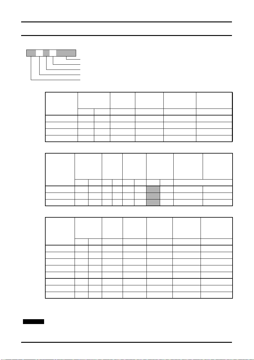
Figure 2-1 Model code explanation
SL A 1 2 XXXXX
Drive kilowatt rating: 00025 = 0.25kW
Drive voltage rating: 2 = 230V, 4 = 400V
Number of input phases: 1 = 1phase, 3 = 3phase, D = 1 and 3phase
Frame size
Model: Commander SL
Table 2-1 Commander SL, 1 phase, 200 to 240VAC ±10%, 48 to 62Hz units
Model
Number
SLA1200025 0.25 0.33 6 4.3 1.7 2.55
SLA1200037 0.37 0.5 10 5.8 2.2 3.3
SLA1200055 0.55 0.75 10 8.1 3.0 4.5
SLA1200075 0.75 1.0 16 10.5 4.0 6.0
Table 2-2 Commander SL, 1 and 3 phase, 200 to 240VAC ±10%, 48 to 62Hz units
Model
Number
SLBD200110 1.1 1.5 16 10 14.2 6.7
SLBD200150 1.5 2.0 20 16 17.4 8.7
SLCD200220 2.2 3.0 25 20 23.2 11.9
Nominal motor
power
kW hp A A A A
Nominal
motor
power
kW hp 1ph 3ph 1ph 3ph 1ph 3ph Heavy Duty
rating
Input fuse
rating
Input
fuse
A
Typical full
Typical
full load
input
current
A
load input
current
Maximum
continuous
input
current
100% RMS
output current
Heavy Duty
100% RMS
current
A
9.2 5.2 7.8
12.6 7.0 10.5
17.0 9.6 14.4
output
A
150% overload
current for 60s
Heavy Duty
current for
150%
overload
60s
A
Table 2-3 Commander SL, 3 phase, 380 to 480VAC ±10%, 48 to 62Hz units
Model
Number
SLB3400037 0.37 0.5 6 1.7 2.5 1.3 1.95
SLB3400055 0.55 0.75 6 2.5 3.1 1.7 2.55
SLB3400075 0.75 1.0 6 3.1 3.75 2.1 3.15
SLB3400110 1.1 1.5 6 4.0 4.6 2.8 4.2
SLB3400150 1.5 2.0 10 5.2 5.9 3.8 5.7
SLC3400220 2.2 3.0 16 7.3 9.6 5.1 7.65
SLC3400300 3.0 3.0 16 9.5 11.2 7.2 10.8
SLC3400400 4.0 5.0 16 11.9 13.4 9.0 13.5
Nominal
motor
power
kW hp A A A A A
Input
fuse
rating
Typical
full load
input
current
Maximum
continuous
input
current
100% RMS
output
current
Heavy Duty
150%
overload
current for 60s
Heavy Duty
Output frequency: 0 to 1500Hz
Output voltage: 3 phase, 0 to drive rating (240 or 480Vac maximum set by Pr 08).
NOTE
The maximum continuous current inputs are used to calculate input cable sizing. Where
no maximum continuous input currents are indicated, use the typical full load input
current values. See Commander SL Technical Data Guide for cable data.
8 Commander SL Getting Started Guide
www.controltechniques.com Issue Number: 2
Page 9
3 Mechanical Installation
Enclosure
The drive is intended to be mounted in an enclosure which prevents access except by
WARNING
Drive
NOTE
trained and authorised personnel, and which prevents the ingress of contamination. It is
designed for use in an environment classified as pollution degree 2 in accordance with
IEC 60664-1. This means that only dry, non-conducting contamination is acceptable.
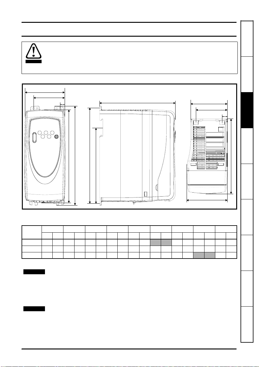
Figure 3-1 Commander SL dimensions
E
D
C
B
I
A
H
G
F
D
E
Mounting holes: 4 x M4 holes
Table 3-1 Commander SL dimensions
size
A 140 5.51 154 6.06 11 0.43 64 2.52 75 2.95 145 5.71 104 4.09 143 5.63
B 190 7.48 205 8.07 10.9 0.43 65.9 2.6 85 3.35 77 3.0 156 6.15 155.5 6.12 194 7.64
C 240 9.45 258 10.16 10.4 0.41 81.1 3.2 100 3.94 91.9 3.62 173 6.81
ABCDEFGH*I
mm in mm in mm in mm in mm in mm in mm in mm in mm in
*Size C is not DIN rail mountable.
If DIN rail mounting is used in an installation where the drive is to be subjected to shock
or vibration, it is recommended that the bottom mounting screws are used to secure the
drive to the back plate.
If the installation is going to be subjected to heavy shock and vibration, then it is
recommended that the drive is surface mounted rather than DIN rail mounted.
C
244 9.61
Safety Information Rating Data
Mechanical
Installation
Installation
Electrical
G
Keypad and
Display
Parameters Diagnostics Options
NOTE
The DIN rail mounting mechanism has been designed so no tools are required to install
and remove the drive from a DIN rail. Please ensure the top mounting lugs are located
correctly on the DIN rail before installation is initiated.
Commander SL Getting Started Guide 9
Issue Number: 2 www.controltechniques.com
Information
UL Listing
Page 10
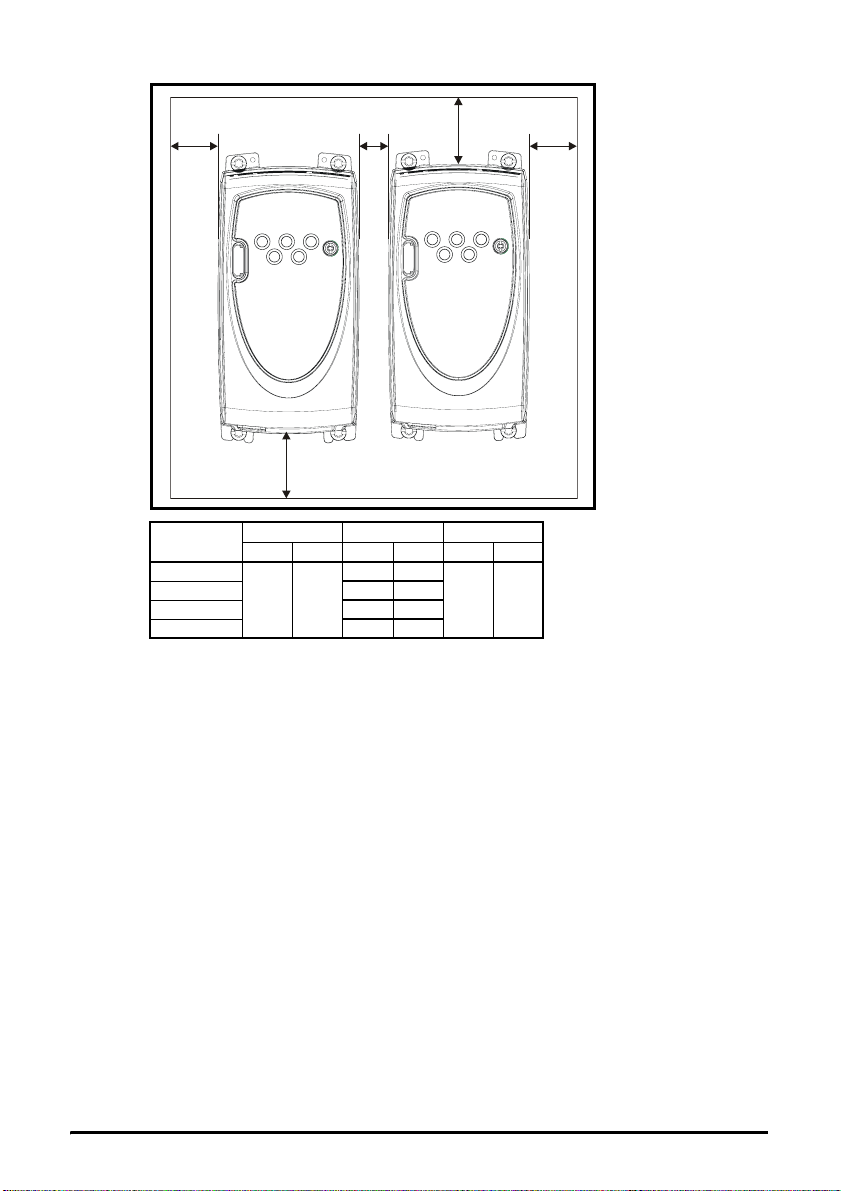
Figure 3-2 Minimum mounting clearances
ABCA
Drive size
A
B (≤0.75kW) 10 0.39
B (≥1.1kW) 0 0
C 50* 1.97*
ABC
mm in mm in mm in
00
10 0.39
C
100 3.94
*This is the minimum spacing between drives at the base of the drive where it is
mounted against a back plate.
10 Commander SL Getting Started Guide
www.controltechniques.com Issue Number: 2
Page 11

4 Electrical Installation
y
y
4.1 Power terminal connections
Figure 4-1 Size A power terminal connections
L1 L2/N U V W PE
Optional
EMC filter
Optional
line reactor
Mains suppl
Figure 4-2 Sizes B and C power terminal connections
L3/N U V W
L1 L2
Optional
ground
connection
PE PE
Supply
ground
Installation
Installation
Display
Safety Information Rating Data
Mechanical
Electrical
Keypad and
PE PE
Supply
ground
Supply
ground
Optional
EMC filter
Optional
line reactor
L3/N U V WL1 L2
Fuses
Optional ground
Mains suppl
connection
Fuses/MCB: The AC supply to the drive must be fitted with suitable protection against
overload and short circuits. Failure to observe this requirement will cause risk of fire.
WARNING
See Chapter 2 Rating Data on page 8 for fuse ratings and the Commander SL Technical
Data Guide for further fuse data.
Commander SL Getting Started Guide 11
Issue Number: 2 www.controltechniques.com
Parameters Diagnostics Options
Information
UL Listing
Page 12
WARNING
WARNING
The drive must be grounded by a conductor sufficient to carry the prospective fault
current in the event of a fault.
To avoid a fire hazard and maintain validity of the UL listing, adhere to the specified
tightening torques for the power and ground terminals. Refer to the table below.
Frame size Maximum power terminal screw torque
A 0.5 N m / 4.4 lb in
B and C 1.4 N m / 12.1 lb in
NOTE
NOTE
When connecting single phase to a dual rated 200V unit, use terminals L1 and L3.
For control terminal connections, see section Pr 05 Drive configuration on page 20.
4.1.1 Ground leakage current
NOTE
There is an internal voltage surge suppression device connected to ground. Under
normal circumstances, this carries negligible current (<1mA).
4.2 EMC
4.2.1 External EMC filters
A full range of external EMC filters are available for Commander SL. An external EMC
filter is required if:
• Operating in the first environment of EN 61800-3
• Conformity to the generic emission standards is required
• Equipment which is sensitive to electrical interference operating nearby
When an EMC filter is used, it is also necessary to:
• Use screened motor cable, with screen clamped to the grounded metal panel
• Use screened control cable, with screen clamped to the grounded metal panel
Full instructions are given in the Commander SL Technical Data Guide.
4.3 Control terminals I/O specification
The control circuits are isolated from the power circuits in the drive by basic insulation
(single insulation) only. The installer must ensure that the external control circuits are
WARNING
WARNING
insulated from human contact by at least one layer of insulation (supplementary
insulation) rated for use at the AC supply voltage.
If the control circuits are to be connected to other circuits classified as Safety Extra Low
Voltage (SELV) (e.g. to personal computer), an additional isolating barrier must be
included in order to maintain the SELV classification.
NOTE
See section Pr 05 Drive configuration on page 20 for terminal connection / set-up
diagrams and details.
NOTE
The digital inputs are positive logic only.
12 Commander SL Getting Started Guide
www.controltechniques.com Issue Number: 2
Page 13
NOTE
0V common
T1
Analogue input 1: voltage, current or digital input
T2
Default: Analogue voltage input
Input range:
Voltage / Current / Digital 0 to +10V / 4 to 20mA / 0 to +24V
Input impedance 100kΩ (voltage) / 200Ω (current) / 6k8 (digital)
Digital input See terminals T6, T7 and T8
The setting of terminal T2 is automatically changed by the setting of Pr 05. See section
Pr 05 Drive configuration on page 20 for details.
+10V reference output
T3
Maximum output current 5mA
Analogue voltage or digital output
T4
Default: Digital output: ‘At zero speed’
Range:
Voltage ouput / Digital output 0 to +10V / 0 to +24V
Maximum output current:
Analogue output
Digital output
5mA
50mA
The total available current from the digital output plus the +24V output is 100mA.
+24V output
T5
Maximum output current 100mA
Installation
Installation
Display
Safety Information Rating Data
Mechanical
Electrical
Keypad and
Digital input - Enable / Reset*/**
T6
Digital input - Run Forward (Edge triggered)**
T7
Digital input - Run Reverse (Edge triggered)**
T8
Logic Positive logic only
Voltage range 0 to +24V
Nominal threshold voltage +10V
The function of terminal T8 is automatically changed by the setting of Pr 05. See section
Pr 05 Drive configuration on page 20 for details.
The function of terminals T6, T7 and T8 can also be changed by the setting of Pr 11.
See section Pr 11 Start/stop logic on page 22 for details.
Commander SL Getting Started Guide 13
Issue Number: 2 www.controltechniques.com
Parameters Diagnostics Options
Information
UL Listing
Page 14

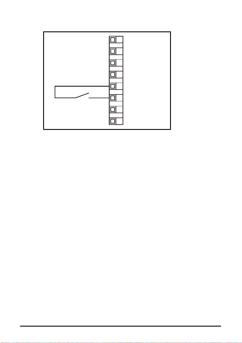
WARNING
T9
Status relay - Drive healthy (normally open)
T10
Voltage rating
Current rating
Contact isolation 1.5kVac (overvoltag e categ ory II )
Operation of contact
240Vac
30Vdc
2Aac 240V
4Adc 30V resistive load (2A 35Vdc for UL requirements)
0.3Adc 30V inductive load (L/R = 40ms)
OPEN
• AC supply removed from drive
• AC supply applied to drive with drive in tripped
condition
CLOSED
• AC supply applied to drive with drive in a 'ready to
run' or 'running' condition (not tripped)
Provide fuse or other over-current protection in status relay circuit.
If the enable terminal is opened, the drives output is disabled and the motor will coast to
a stop. The drive cannot be re-enabled until 1.0s has elapsed since it was disabled.
* Following a drive trip, opening and closing the enable terminal will reset the drive.
If the run forward or run reverse terminal is closed, the drive will run straight away.
** Following a drive trip and a reset via the stop/reset key , the enable, run forward or
run reverse terminals will need to be opened and closed to allow the drive to run.
This ensures that the drive does not run when the stop/reset key is pressed.
The enable, run forward and run reverse terminals are level triggered apart from after a
trip where they become edge triggered. See * and ** by terminals T6, T7 and T8 on
page 13.
If the enable and run forward or enable and run reverse terminals are closed when the
drive is powered up, the drive will run straight away up to the set speed.
14 Commander SL Getting Started Guide
www.controltechniques.com Issue Number: 2
Page 15

5 Keypad and Display
Figure 5-1 Keypad and display
M
5.1 Programming keys
M
The MODE key is used to change the mode of operation of the drive.
The UP and DOWN keys are used to select parameters and edit their values. In
keypad mode, they are used to increase and decrease the speed of the motor.
5.2 Control keys
The START key is used to start the drive in keypad mode.
The STOP/RESET key is used to stop and reset the drive in keypad mode. It can
also be used to reset the drive in terminal mode.
5.3 Display indications
Status Modes
Display
mnemonic
Status Explanation
Drive ready
Drive inhibited
DC injection braking DC injection braking current is being applied to the motor.
The drive is enabled and ready for a start command. The
output bridge is inactive.
The drive is inhibited because there is no enable command,
or a coast to stop is in progress or the drive is inhibite d during
a trip reset.
Safety Information Rating Data
Mechanical
Installation
Installation
Electrical
Keypad and
Display
Parameters Diagnostics Options
When the drive is running, the display indicates the drive output frequency.
Commander SL Getting Started Guide 15
Issue Number: 2 www.controltechniques.com
Information
UL Listing
Page 16
5.4 Selecting and changing parameters
NOTE
This procedure is written from the first power up of the drive and assumes no terminals
have been connected, no parameters have been changed and no security has been set.
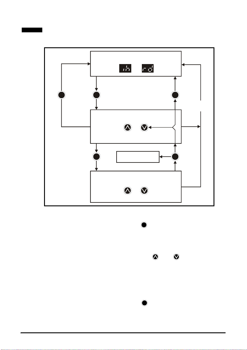
Figure 5-2
STATUS MODE
or
Hold
for 2s
M
Press and
release
M
PARAMETER VIEW MODE
Select parameter to view
orPress
Parameter number and parameter
value flashing alternately
Press and
M
release
4 mins
timeout
Press and
release
M M
5.5 Saving parameters
Parameters are automatically saved when the MODE key is pressed when going
from parameter edit mode to parameter view mode.
5.6 Parameter access
There is only one level of parameter access. All parameters are accessible from default
by scrolling through the parameters by pressing the UP or DOWN keys.
The setting of user security Pr 25 determines whether the parameter access is read only
(RO) or read write (RW)
5.7 Security codes
Setting a security code allows view only access to all parameters.
A security code is locked into the drive when Pr 25 is set to any value other than 0 and
then LoC is selected in Pr 10. On pressing the MODE key, Pr 10 is automatically
changed from LoC to OPEn and Pr 25 will automatically be set to 0 as not to reveal the
security code.
Parameters
saved
PARAMETER EDIT MODE
Change parameter value
orPress
Parameter value flashing
M
M
Press and
release
16 Commander SL Getting Started Guide
www.controltechniques.com Issue Number: 2
Page 17

5.7.1 Setting a security code
•Set Pr 25 to the desired security code e.g. 5
•Set Pr 10 to LoC
• Press the MODE key
M
•Pr 10 will now be reset to OPEn and Pr 25 will be reset to 0
• The security code will now be locked into the drive
• Security will also be set if the drive is powered down after a security code has been
set into Pr 25
5.7.2 Unlocking a security code
• Select parameter to be edited
• Press the MODE key, the display will flash 'CodE'
M
• Press the UP key to enter the correct security code
• Press the MODE key
M
• If the correct security code has been entered, the display will now flash the
parameter value and this can be adjusted
• If the security code has been entered incorrectly, the display will return to parameter
view mode
5.7.3 Re-locking security
When a security code has been unlocked and the required parameter changes made, to
re-lock the same security code:
•Set Pr 10 to LoC
• Press the MODE key
M
5.7.4 Setting security back to 0 (zero) - no security
• Go to Pr 25
• Unlock security as above
•Set Pr 25 to 0
M
NOTE
• Press the MODE key
If a security code has been lost of forgotten, please contact your local drive centre or
distributor.
5.7.5 Setting the drive back to default values
•Set Pr 29 to Eur and press the MODE key. This loads 50Hz default parameters
or
•Set Pr 29 to USA and press the MODE key. This loads 60Hz default parameters
M
M
Safety Information Rating Data
Mechanical
Installation
Installation
Electrical
Keypad and
Display
Parameters Diagnostics Options
Commander SL Getting Started Guide 17
Issue Number: 2 www.controltechniques.com
Information
UL Listing
Page 18

6 Parameters
6.1 Parameter descriptions
No Function Range Defaults Description
01 Minimum set speed
Maximum set
02
speed
03 Acceleration rate
04 Deceleration rate
05* Drive configuration
06 Motor rated current
07 Motor rated speed
08 Motor rated voltage
09 Motor power factor 0 to 1 0.85
10 Parameter access OPEn, LoC OPEn
Start/Stop logic
11*
select
15 Jog reference
Enable negative
17
preset speeds
18 Preset speed 1
19 Preset speed 2
20 Preset speed 3
21 Preset speed 4
25 Security set-up 0 to 9999 0
0.0 to Pr 02
Hz
0.0 to 1500 HzEur: 50.0
0.0 to 3200
s/100Hz
AV, AI, AV.Pr,
AI.Pr, Pr, PAd
0.0 to drive
rated current ADrive rating
0 to 9999
rpm
0 to 240 V
0 to 480 V
0 to 4
0.0 to 400.0
Hz
OFF, On OFF
±1500 Hz
(Limited by
setting of Pr
Maximum set
02
speed)
0.0
USA: 60.0
Eur: 5.0
USA: 33.0
Eur: 10.0
USA: 33.0
Eur: AV
USA: PAd
Eur: 1500
USA: 1800
Eur: 230 / 400
USA: 230 / 460
Eur: 0
USA: 4
1.5 Defines the jog speed
0.0 Defines preset speeds 1 to 4
Used to set the minimum speed at which the
motor will run in both directions
Used to set the maximum speed at which the
motor will run in both directions
Sets the acceleration and deceleration rate of
the motor in both directions in seconds/100Hz
The setting of Pr 05 automatically sets up the
drives configuration.
See section Pr 05 Drive config ur a t i o n on
page 20 for further details.
Enter the motor current rating (taken from the
motor name plate).
Motor rated current must be set
correctly to avoid a risk of fire in the
event of a motor overload
WARNING
Enter the rated full load speed of the motor
(taken from the motor name plate)
Enter the motor rated voltage (taken from the
motor name plate)
Enter the motor rated power factor cos ϕ (taken
from the motor name plate)
OPEn: All parameters can be accessed
LoC: Used to lock a security code in the drive
See section 5.7 Security codes on page 16 for
further details
This parameter changes the functions of
terminals 6, 7 and 8 which are normally
associated with enabling, stopping and starting
the drive.
See section Pr 11 Start/stop log ic on page 22
for further details.
OFF: Direction of rotation controlled by run
forward and run reverse terminals
On: Direction of rotation controlled by preset
speed values (use run forward terminal)
Used to set-up a user security code.
See section 5.7 Security codes on page 16
18 Commander SL Getting Started Guide
www.controltechniques.com Issue Number: 2
Page 19

No Function Range Defaults Description
0: Keypad reference is zero
Power up keypad
27
reference
29* Load defaults no, Eur, USA no
30 Ramp mode select 0 to 3 1
Stopping mode
31
select
Dynamic V to f
32
select
Catch a spinning
33#
motor select
Terminal T4 output
35*
mode select
Maximum switching
37
frequency
Motor rated
39
frequency
Number of motor
40
poles
0, LASt, PrS1 0
0 to 4 1
OFF, On OFF
0 to 3 0
Fr, Ld, A, Por ,
n=0, At.SP,
Lo.SP , hEAL,
Act, ALAr,
I.Lt, At.Ld
3, 6, 12, 18**
kHz
0.0 to 1500 HzEur: 50.0
Auto, 2P , 4P,
6P, 8P
USA: 60.0
Auto
Fr
3
LASt: Keypad reference is last value selected
before the drive was powered down
PrS1: Keypad reference is copied from preset
speed 1
no: Defaults are not loaded
Eur: 50Hz default parameters are loaded
USA: 60Hz default parameters are loaded
0: Fast ramp select
1: Standard ramp with normal motor voltage
selected
2: Standard ramp with high motor voltage
selected
3: Fast ramp with high motor voltage selected
0: Coast to stop selected
1: Ramp to stop selected
2: Ramp to stop with 1 second DC injection
braking
3: DC injection braking with the detection of
zero speed
4: Timed DC injection braking
OFF: Fixed linear voltage to frequency ratio
(constant torque - standard load)
On: Voltage to frequency ration dependant on
load current (dynamic/variable torque load)
0: Disabled
1: Detect positive and negative frequencies
2: Detect positive frequencies only
3: Detect negative frequencies only
Analogue output modes
Fr: Volt age proportional to motor speed
Ld: Volt age proportional to motor load
A: Voltage propor tional to output current
Por: Voltage pr oportional to output power
Digital output modes
n=0: At zero speed
At.SP: At speed
Lo.SP: At minimum speed
hEAL: Drive healthy
Act: Drive active
ALAr: General drive alarm
I.Lt: Current limit active
At.Ld: At 100% load
3: 3kHz
6: 6kHz
12: 12kHz
18: 18kHz
Enter the motor rated frequency (taken from the
motor rated name plate)
Auto: Automatically calculates the number of
motor poles from the settings of Pr 07 and Pr 39
2P: Set for a 2 pole motor
4P: Set for a 4 pole motor
6P: Set for a 6 pole motor
8P: Set for a 8 pole motor
**
Safety Information Rating Data
Mechanical
Installation
Installation
Electrical
Keypad and
Display
Parameters
Diagnostics Options
Information
UL Listing
Commander SL Getting Started Guide 19
Issue Number: 2 www.controltechniques.com
Page 20

No Function Range Defaults Description
Ur S: Stator resistance is measured each time
the drive is enabled and run
Voltage mode
41##
select
Low frequency
42
voltage boost
45 Software version 0.00 to 99.99 Indicates the software version fitted to the drive
55 Last trip
56 Trip before Pr 55
57 Trip before Pr 56
58 Trip before Pr 57
Ur S, Ur, Fd,
Ur A, Ur I,
SrE
0.0 to 50.0 % 3.0
Fd
notr
(no trip)
Ur: No measurement is taken
Fd: Fixed boost
Ur A: St ator resist ance is measured the first time
the drive is enabled and run
Ur I: Stat or resistance is measured at each
power-up when the drive is enabled and run
SrE: Square law characteristic
Determines the boost level when Pr 41 is set to
Fd or SrE
Indicates drive trip codes.
See Chapter 8 Diagnostics on page 28.
NOTES:
* A change to these parameters is set by pressing the MODE key on exit from
M
parameter edit mode. The drive must be disabled, stopped or tripped for a change
to take place. If these parameters are changed while the drive is running, when the
M
MODE key is pressed on exit from parameter edit mode, the parameter will
change back to its previous value.
** Not available on Commander SL Size B and C 400V units.
# If the drive is configured in fixed boost mode (Pr 41 = Fd or SrE) with catch a
spinning motor software enabled, an autotune (see Pr 41) must be carried out to
measure the motor's stator resistance beforehand. If a stator resistance is not
measured, the drive may trip on OV or OI.AC while trying to catch a spinning motor.
## In all Ur modes, the drive operates in open loop vector mode. The motor/load must
be stationary before an autotune is carried out when one of the Ur modes is
selected. Carrying out an autotune when the motor/load is not stationary could
result in poor motor performance or OI.AC, It.AC or OV trips.
With USA defaults, the STOP key will be enabled.
Pr 05 Drive configuration
In all of the settings below, the status relay is set up as a drive healthy relay:
T9
OK Fault
Configuration Description
AV Voltage input
AI Current input
AV.Pr Voltage input with 1 preset speed
AI.Pr Current input with 1 preset speed
Pr 4 preset speeds
PAd Keypad control
20 Commander SL Getting Started Guide
www.controltechniques.com Issue Number: 2
Page 21

Figure 6-1 Pr 05 = AV Figure 6-2 Pr 05 = AI
t
t
e
T1
0V
reference input (AI)
0V
Current speed
+24V
10k
(2kmin)
0V
Voltage speed
T2
reference input (AV)
+10V reference
T3
output
Digital output
T4
(zero speed)
+24V output
T5
Drive enable/reset
T6
(USA: /Stop)
Run forward
T7
(USA: Run)
Run reverse
T8
(USA: Jog)
+24V
Figure 6-3 Pr 05 = AV.Pr Figure 6-4 Pr 05 = AI.Pr
T1
0V
Voltage speed
T2
reference input (AV)
+10V reference
T3
output
Digital output
T4
(zero speed)
+24V output
T5
Drive enable/reset
T6
(USA: /Stop)
Run forward
T7
(USA: Run)
Voltage speed
reference input /
T8
preset speed select
+24V
10k
(2kmin)
0V
T8 Reference selected
Open Voltage speed reference input (AV)
Closed Preset speed 2 (Pr 19)
+24V
Current speed
reference input (AI)
0V
T8 Reference selected
Open Current speed reference input (AI)
Closed Preset speed 2 (Pr 19)
Figure 6-5 Pr 05 = Pr Figure 6-6 Pr 05 = PAd
T1
0V
T2
Reference select
+10V reference
T3
+24V
output
Digital output
T4
0V
(zero speed)
+24V output
T5
Drive enable/rese
T6
(USA: /Stop)
Run forward
T7
(USA: Run)
T8
Reference select
+24V
0V
T1
0V
Current speed
T2
reference input (AI)
+10V reference
T3
output
Digital output
T4
(zero speed)
+24V output
T5
Drive enable/reset
T6
(USA: /Stop)
Run forward
T7
(USA: Run)
Run reverse
T8
(USA: Jog)
T1
0V
Current speed
T2
reference input (AI)
+10V reference
T3
output
Digital output
T4
(zero speed)
+24V output
T5
Drive enable/reset
T6
(USA: /Stop)
Run forward
T7
(USA: Run)
Current speed
reference input /
T8
preset speed selec
T1
0V
Not used
T2
+10V referenc
T3
output
Digital output
T4
(zero speed)
+24V output
T5
Drive enable/
T6
reset
T7
Not used
T8
Not used
Safety Information Rating Data
Mechanical
Installation
Installation
Electrical
Keypad and
Display
Parameters
Diagnostics Options
T2 T8 Reference selected
Open Open Preset speed 1 (Pr 18)
Closed Open Preset speed 2 (Pr 19)
Open Closed Preset speed 3 (Pr 20)
Closed Closed Preset speed 4 (Pr 21)
Commander SL Getting Started Guide 21
Issue Number: 2 www.controltechniques.com
Information
UL Listing
Page 22

Pr 11 Start/stop logic
e
t
Figure 6-7 Pr 11 = 0 Figure 6-8 Pr 11 = 1
+24V output
T5
Drive enable/
T6
reset
T7
Run forward
T5
T6
T7
+24V output
/Stop
Run forward
T8 Run reverse
T8 Run reverse
Figure 6-9 Pr 11 = 2 Figure 6-10 Pr 11 = 3
+24V output
+24V output
T5
Drive enable/
T6
reset
T7
Run
T8 Forward / revers
T5
T6
/Stop
T7
Run
T8 Forward / reverse
Figure 6-11 Pr 11 = 4
+24V outpu
T5
/Stop
T6
Run
T7
T8 Jog
NOTE
The function of terminal T8 is automatically changed by the setting of Pr 05 if preset
speeds are being used. See section Pr 05 Drive configuration on page 20 for details.
6.2 Diagnostic parameters
No Function Range Type
Frequency reference selected ± Pr 02 Hz RO
81
Pre-ramp reference ± Pr 02 Hz RO
82
Post-ramp reference ± Pr 02 Hz RO
83
DC bus voltage 0 to drive maximum VDC RO
84
Motor frequency ± Pr 02 Hz RO
85
Motor voltage 0 to drive rating V RO
86
Motor speed ± 9999 rpm RO
87
Motor current + Drive maximum A RO
88
Reference enabled indicator OFF or On RO
91
Reverse selected indicator OFF or On RO
92
Jog selected indicator OFF or On RO
93
Analogue input level 0 to 100 % RO
94
22 Commander SL Getting Started Guide
www.controltechniques.com Issue Number: 2
Page 23

Analogue input
T2
Digital I/O
T10
T9
T4
T6
T7
T8
Input
B4
terminals
Output
B3
terminals
Figure 6-12 Diagnostics logic diagram
(%)
94
select
Reference
selected
(Hz)
X-1
Jog
reference
15
0
1
81
Jog
selected
93
Reverse
11
31
selected
92
Reference
enabled
91
measurement
Key
Read-write (RW)
XX
parameter
Read-only (RO)
XX
parameter
Analogue
input 1
Sequencer
Start/stop
logic select
Stop mode
1
0
Current
Speed clamps
Minimum
01
speed
Maximum
02
speed
0Hz
Motor current
DC bus
voltage
88
1
0
84
Pre-ramp
reference (Hz)
82
Post-ramp
reference
(Hz)
06
07
08
09
32
37
39
40
41
42
Ramps
Acceleration
03
rate
Deceleration
04
rate
Ramp mode
30
select
83
Motor control
Motor rated
current
Motor rated
speed
Motor rated
voltage
Motor power
factor
Dynamic V to f
select
Switching
frequency
Motor rated
frequency
No. of motor
poles
Voltage
mode select
Voltage
boost
Parameter
access
10
Motor
frequency
85
Motor
voltage
86
Motor
speed
rpm
87
Safety Information Rating Data
Mechanical
Installation
Installation
Electrical
Keypad and
Display
Parameters
Commander SL Getting Started Guide 23
Issue Number: 2 www.controltechniques.com
Diagnostics Options
Information
UL Listing
Page 24

7 Quick Start Commissioning
E
This procedure is written from default parameter settings as the drive would be
delivered from the factory.
For European default settings refer to section 7.1 Terminal control .
For USA default settings refer to section 7.2 Keypad control on page 26.
7.1 Terminal control
Figure 7-1 Minimum required control terminal connections
ur
10k
(2kmin)
T1
0V
Voltage speed
T2
reference input (AV)
+10V reference
T3
output
Digital output
T4
(zero speed)
+24V output
T5
Drive enable/reset
T6
Run forward
T7
T8 Run reverse
24 Commander SL Getting Started Guide
www.controltechniques.com Issue Number: 2
Page 25

Action Detail
Ensure:
• The drive enable signal is not given, terminal T6 is open
Before power up
• The run signal is not given, terminal T7/T8 is open
• The motor is connected to the drive
• The motor connection is correct for the drive ∆ or Y
• The correct supply voltage is connected to the drive
Power up the
drive
Enter minimum
and maximum
speeds
Enter
acceleration and
deceleration
rates
Ensure:
• The drive displays:
Enter:
• Minimum speed Pr 01 (Hz)
• Maximum speed Pr 02 (Hz)
Enter:
• Acceleration rate Pr 03 (s/100Hz)
• Deceleration rate Pr 04 (s/100Hz)
Enter:
• Motor rated current in Pr 06 (A)
Enter motor
nameplate
details
• Motor rated speed in Pr 07 (rpm)
• Motor rated voltage in Pr 08 (V)
• Motor rated power factor in Pr 09
• If the motor is not a standard 50/60Hz motor, set Pr 39
accordingly
Ready to run
Enable and run
the drive
Close:
• The enable and run forward or run reverse signals.
Run The drive is now ready to run the motor.
Increasing and
decreasing speed
Turning the speed potentiometer will increase and decrease
the speed of the motor.
To stop the motor under ramp control, open either the run
Stopping
forward or run reverse terminal.
If the enable terminal is opened while the motor is running,
the motor will coast to a stop.
Pr 02
Pr 01
100Hz
Pr 03
Mot X XXXXXXXXX
No XXXXXXXXXX kg
IP55 I.cl F C 40 s S1
°
VHzmin-1kW cosφA
230
50 1445 2.20 0.80 8.50
400
CN = 14.5Nm
240
50 1445 2.20 0.76 8.50
415
CN = 14.4Nm
CTP- VEN 1PHASE 1=0,46A P=110W R.F 32MN
Safety Information Rating Data
Mechanical
Installation
t
t
Pr 04
Installation
Electrical
4.90
4.90
Keypad and
I.E.C 34 1(87)
Display
Parameters
Commissioning
Quick Start
Commander SL Getting Started Guide 25
Issue Number: 2 www.controltechniques.com
Options
Information
UL Listing
Page 26
7.2 Keypad control
e
Figure 7-2 Minimum required control terminal connections
USA
T1
0V
T2
Not used
+10V referenc
T3
output
Digital output
T4
(zero speed)
+24V output
T5
Drive enable/
T6
reset
T7
Not used
Not used
T8
26 Commander SL Getting Started Guide
www.controltechniques.com Issue Number: 2
Page 27

Action Detail
Ensure:
• The drive enable signal is not given, terminal T6 is open
Before power up
• The motor is connected to the drive
• The motor connection is correct for the drive ∆ or Y
• The correct supply voltage is connected to the drive
Power up the
drive
Enter minimum
and maximum
speeds
Enter
acceleration and
deceleration
rates
Ensure:
• The drive displays:
Enter:
• Minimum speed Pr 01 (Hz)
• Maximum speed Pr 02 (Hz)
Enter:
• Acceleration rate Pr 03 (s/100Hz)
• Deceleration rate Pr 04 (s/100Hz)
Enter:
• Motor rated current in Pr 06 (A)
Enter motor
nameplate
details
• Motor rated speed in Pr 07 (rpm)
• Motor rated voltage in Pr 08 (V)
• Motor rated power factor in Pr 09
• If the motor is not a standard 50/60Hz motor, set Pr 39
accordingly
Ready to run
Enable and run
the drive
Close:
• The enable signal
• Press the START key
Run The drive is now ready to run the motor.
Increasing and
decreasing speed
Stopping
Press the UP key to increase the speed
Press the DOWN key to decrease the speed
Press the STOP/RESET key to stop the motor
Pr 02
Pr 01
100Hz
Pr 03
Mot X XXXXXXXXX
No XXXXXXXXXX kg
IP55 I.cl F C 40 s S1
°
VHzmin-1kW cosφA
230
50 1445 2.20 0.80 8.50
400
CN = 14.5Nm
240
50 1445 2.20 0.76 8.50
415
CN = 14.4Nm
CTP- VEN 1PHASE 1=0,46A P=110W R.F 32MN
Safety Information Rating Data
Mechanical
Installation
t
t
Pr 04
Installation
Electrical
4.90
4.90
I.E.C 34 1(87)
Keypad and
Display
Parameters
Commissioning
Quick Start
Commander SL Getting Started Guide 27
Issue Number: 2 www.controltechniques.com
Options
Information
UL Listing
Page 28

8 Diagnostics
Do not attempt to carry out internal repairs. Return a faulty drive to the supplier for repair.
WARNING
Trip code
UU
OU
OI.AC**
O.SPd
It.AC
O.ht1
O.ht2
O.ht3
EEF
O.Ld1*
PH
O.cL
rS
HFxx
trip
DC bus under voltage Low AC supply voltage
DC bus over voltage Deceleration rate set too fast for the inertia of the machine
Drive output instantaneous over
current
Over speed
I2t on drive output current
Drive over-heat (IGBT junctions) on
thermal model
Over heat based on drives heatsink Heatsink temperat ure exceeds allowable maximum
Drive over-heat based on thermal
model
Internal drive EEPROM failure
User +24V or digital output overload Excessive load or short circuit on +24V output
Input phase imbalance or input
phase loss
Overload on current loop input Input current exceeds 25mA
Failure to measure motors stator
resistance
Hardware faults
Condition Possible cause
Insufficient ramp times
Phase to phase or phase to ground short circuit on the drives output
Excessive motor speed (typically caused by mechanical load
driving the motor)
Excessive mechanical load
High impedance phase to phase or phase to ground short
circuit at drive output
Thermal model based on IGBT junction temperature exceeds
allowable maximum
Drive thermal protection accumulator has reached 100%
Possible loss of parameter values
(set default parameters (see Pr
One of the input phases has become disconnected from the
drive (applies to 200/400V three phase drives only, not dual
rated drives)
Motor too small for drive
Motor cable disconnected during measurement
Internal drive hardware fault (see Commander SL Technical
Data Guide)
29* on page 19))
* The Enable/Reset terminal will not reset an O.Ld1 trip. Use the Stop/Reset key.
** This trip cannot be reset for 10 seconds after it occurs.
Table 8-1 DC bus voltages
Drive voltage rating UV Trip UV Reset OV trip
200V 175 215 * 415
400V 330 425 * 830
NOTE
* These are the absolute minimum DC voltages the drives can be supplied by.
Table 8-2 Alarm warnings
Display Condition Solution
OUL.d
AC.Lt
NOTE
I x t overload Reduce motor current
Heatsink/IGBT temperature high Reduce ambient temperature or reduce motor current
hot
Drive current limit is active Reduce motor current
If no action is taken wh en an alarm warning appears, the drive w ill trip on the appropriate fault code.
28 Commander SL Getting Started Guide
www.controltechniques.com Issue Number: 2
Page 29

Cooling fan control (size B and C only)
As default, the drive’s cooling fan is controlled by the drive. The fan will remain off until
the heatsink temperature reaches 60°C or the output current rises above 75% of the
drive rating. The fan will then switch on and run at full speed for a minimum of 20s.
Safety Information Rating Data
Mechanical
Installation
Installation
Electrical
Keypad and
Display
Commander SL Getting Started Guide 29
Issue Number: 2 www.controltechniques.com
Parameters
Diagnostics
Options
Information
UL Listing
Page 30
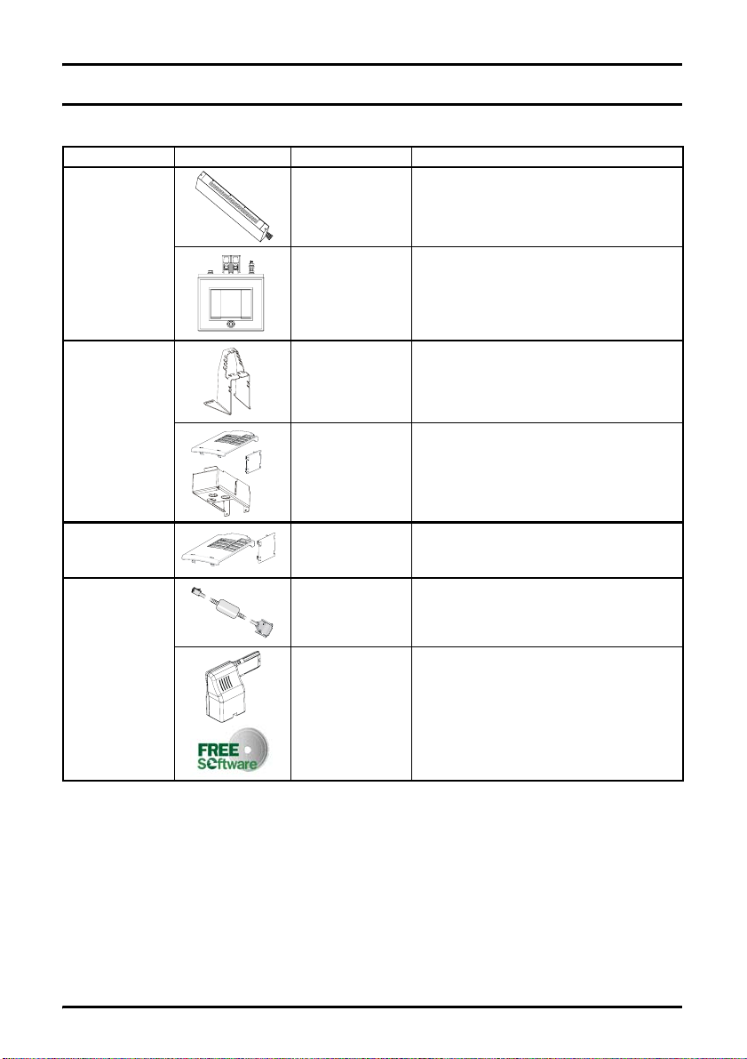
9Options
Type Option Name Further details
EMC
Cable
management
Cover kit Cover kit
CT Comms cable
Communications
Commissioning
EMC Filters
AC input line
reactors
SL-Bracket Cable management bracket
UL type 1 kit
Easy
pack
These filters are designed to operate in area s of
sensitive equipment
To reduce supply harmonics
Bottom metal gland plate, top cover and side
covers to allow the drive to comply with the
requirements of UL type 1
The additional cover kit will increase the
environmental protection of the top face to IP4X
in vertical direction.
Cable with isolation RS232 to RS485 converter .
For connecting PC/Laptop to the drive fitted
with EIA485 (RJ45) Comms Adaptor when
using the Paramer tool software
Consists of:
1 x EIA485 (RJ45) Comms Adaptor.
1 x CD Rom containing Parameter tool
software.
Software for PC or Laptop which allows the
user to commission and store parameter
settings
30 Commander SL Getting Started Guide
www.controltechniques.com Issue Number: 2
Page 31

10 UL Listing Information
Table 10-1 Approvals
CE approval Europe
C Tick approval Australia
UL / cUL approval USA & Canada
R
Safety Information Rating Data
10.1 UL information (for Commander SL size A, B and C)
10.1.1 Conformity
The drive conforms to UL listing requirements only when the following are observed:
• Class 1 60/75°C (140/167°F) copper wire only is used in the installation
• The ambient temperature does not exceed 40°C (104°F) when the drive is
operating
• The terminal tightening torques specified in section 4.1 Power terminal connections
are used
• The drive is installed into a separate electrical enclosure. The drive has a UL
‘Opentype’ enclosure rating.
• UL listed class CC fast acting fuses e.g. Bussman Limitron KTK series, Gould AmpTrap ATM series or equivalent are used in the AC supply.
10.1.2 AC supply specification
The drive is suitable for use in a circuit capable of delivering not more than 100,000
RMS symmetrical Amperes at 264Vac RMS maximum (200V drives), 528Vac RMS
maximum (400V drives).
10.1.3 Motor overload protection
The drive provides motor overload protection. The overload protection level is 150% of
full-load current. It is necessary for the motor rated current to be entered into Pr 06 for
the protection to operate correctly. The protection level may be adjusted below 150% if
required.
10.1.4 Overspeed protection
The drive provides overspeed protection. However, it does not provide the level of
protection afforded by an independent high integrity overspeed protection device.
Mechanical
Installation
Installation
Electrical
Keypad and
Display
Parameters Diagnostics Options
Commander SL Getting Started Guide 31
Issue Number: 2 www.controltechniques.com
Information
UL Listing
Page 32

0VA1+10V
T3 T4 T5 T6T1 T2 T7
Eur
+24V
0V
USA
+24V
0V
AO
+24V
DIN1
DIN2
T8 T9
DIN3
10k
(2kmin)
10k
(2kmin)
1
RL2
RL1
2
T1
0V
Voltage speed
T2
reference input (AV)
+10V reference
T3
output
Digital output
T4
(zero speed)
+24V output
T5
Drive enable/
T6
reset
T7
Run forward
T8 Run reverse
T9
OK Fault
T1
0V
Voltage speed
T2
reference input (AV)
+10V reference
T3
output
Digital output
T4
(zero speed)
+24V output
T5
/Stop
T6
T7
Run
T8 Jog
T9
OK Fault
0472-0024-02
 Loading...