

Page 1

Advanced User Guide
Commander SK
AC variable speed drive for 3
phase induction motors from
0.25kW to 110kW, 0.33hp to
150hp
Part Number: 0472-0001-09
Issue: 9
www.controltechniques.com
Page 2

General Information
The manufacturer accepts no liability for any consequences resulting from inappropriate, negligent or incorrect
installation or adjustment of the optional operating parameters of the equipment or from mismatching the variable speed
drive with the motor.
The contents of this guide are believed to be correct at the time of printing. In the interests of a commitment to a policy
of continuous development and improvement, the manufacturer reserves the right to change the specification of the
product or its performance, or the contents of the guide, without notice.
All rights reserved. No parts of this guide may be reproduced or transmitted in any form or by any means, electrical or
mechanical including photocopying, recording or by an information storage or retrieval system, without permission in
writing from the publisher.
Drive software version
This product is supplied with the latest software version. If this drive is to be connected to an existing system or machine,
all drive software versions should be verified to confirm the same functionality as drives of the same model already
present. This may also apply to drives returned from a Control Techniques Service Centre or Repair Centre. If there is
any doubt please contact the supplier of the product.
The software version of the drive can be checked by looking at Pr 11.29 and Pr 11.34. This takes the form of xx.yy.zz
where Pr 11.29 displays xx.yy and Pr 11.34 displays zz. (e.g. for software version 01.01.00, Pr 11.29 = 1.01 and Pr 11.34
displays 0).
Environmental statement
Control Techniques is committed to minimising the environmental impacts of its manufacturing operations and of its
products throughout their life cycle. To this end, we operate an Environmental Management System (EMS) which is
certified to the International Standard ISO 14001. Further information on the EMS, our Environmental Policy and other
relevant information is available on request, or can be found at www.greendrives.com.
The electronic variable-speed drives manufactured by Control Techniques have the potential to save energy and
(through increased machine/process efficiency) reduce raw material consumption and scrap throughout their long
working lifetime. In typical applications, these positive environmental effects far outweigh the negative impacts of product
manufacture and end-of-life disposal.
Nevertheless, when the products eventually reach the end of their useful life, they must not be discarded but should
instead be recycled by a specialist recycler of electronic equipment. Recyclers will find the products easy to dismantle
into their major component parts for efficient recycling. Many parts snap together and can be separated without the use
of tools, whilst other parts are secured with conventional fasteners. Virtually all parts of the product are suitable for
recycling.
Product packaging is of good quality and can be re-used. Large products are packed in wooden crates, while smaller
products come in strong cardboard cartons which themselves have a high recycled fibre content. If not re-used, these
containers can be recycled. Polythene, used on the protective film and bags for wrapping product, can be recycled in the
same way. Control Techniques' packaging strategy prefers easily-recyclable materials of low environmental impact, and
regular reviews identify opportunities for improvement.
When preparing to recycle or dispose of any product or packaging, please observe local legislation and best practice.
REACH legislation
EC Regulation 1907/2006 on the Registration, Evaluation, Authorisation and restriction of Chemicals (REACH) requires
the supplier of an article to inform the recipient if it contains more than a specified proportion of any substance which is
considered by the European Chemicals Agency (ECHA) to be a Substance of Very High Concern (SVHC) and is
therefore listed by them as a candidate for compulsory authorisation.
For current information on how this requirement applies in relation to specific Control Techniques products, please
approach your usual contact in the first instance. Control Techniques position statement can be viewed at:
http://www.controltechniques.com/REACH
Copyright © August 2013 Control Techniques Ltd.
Issue Number: 9
Software: 01.08.00 (Size A to D)
01.08.06 (Size 2 to 6)
Page 3

Contents
1 Introduction....................................................................................................................4
2 Parameter x.00 ...............................................................................................................5
2.1 Saving parameters .................................................................................................................................5
2.2 Loading default parameters ...................................................................................................................5
2.3 Eur/USA parameter set differences .......................................................................................................5
3 Parameter description format.......................................................................................6
3.1 Software variable maximum term definitions .........................................................................................6
3.2 Parameter information ...........................................................................................................................7
3.3 Key to parameter codes .........................................................................................................................8
3.4 Sources and destinations ......................................................................................................................9
3.5 Sample/update times .............................................................................................................................9
4 Keypad and display .....................................................................................................10
4.1 Programming keys ...............................................................................................................................10
4.2 Control keys .........................................................................................................................................10
4.3 Selecting and changing parameters ....................................................................................................10
5 Serial communications ...............................................................................................12
5.1 Introduction ..........................................................................................................................................12
5.2 EIA232 to EIA485 communications .....................................................................................................12
5.3 Serial communications connections ....................................................................................................14
6 CT Modbus RTU...........................................................................................................16
6.1 CT Modbus RTU specification .............................................................................................................16
7 PLC Ladder programming .........................................................................................24
8 CTSoft ...........................................................................................................................26
9 Menu 0 ..........................................................................................................................30
10 Advanced parameter descriptions.............................................................................33
10.1 Overview ..............................................................................................................................................33
10.2 Menu 1: Speed reference selection, limits and filters ..........................................................................34
10.3 Menu 2: Ramps ...................................................................................................................................46
10.4 Menu 3: Speed sensing thresholds and frequency input and output ...................................................55
10.5 Menu 4: Current control .......................................................................................................................61
10.6 Menu 5: Motor control ..........................................................................................................................72
10.7 Menu 6: Drive sequencer and clock ....................................................................................................84
10.8 Menu 7: Analog inputs and outputs ...................................................................................................101
10.9 Menu 8: Digital inputs and outputs ....................................................................................................109
10.10 Menu 9: Programmable logic, motorized pot and binary sum ...........................................................118
10.11 Menu 10: Status logic and diagnostic information .............................................................................128
10.12 Menu 11: General drive set-up ..........................................................................................................138
10.13 Menu 12: Programmable threshold and variable selector .................................................................152
10.14 Menu 14: PID controller .....................................................................................................................165
10.15 Menu 15: Solutions Module set-up ....................................................................................................171
10.16 Menu 18: Application menu 1 ............................................................................................................185
10.17 Menu 20: Application menu 2 ............................................................................................................187
10.18 Menu 21: Second motor map ............................................................................................................188
Comma nder SK A dvanced User Gui de 3
Issue Number: 9 www.controltechniques.com
Page 4

Introduction Parameter x.00
Parameter
description format
Keypad and
display
Serial
communications
CT Modbus
RTU
CT Modbus
RTU
CTSoft Menu 0
Advanced parameter
descriptions
1 Introduction
This Advanced User Guide provides information on the more advanced features and parameters of Commander SK:
• Parameter types
• Keypad and display information
• Modbus RTU serial communications protocol
• PLC Ladder logic programming
• CTSoft Windows™ based commissioning and monitoring tool
• Advanced parameter logic diagrams and full parameter descriptions
• Commander SK Solutions Module logic diagrams and parameter descriptions
Commander SK
The Commander SK is an open loop vector AC variable speed inverter drive used to control the speed of an AC induction motor. The drive uses an
open loop vector control strategy to maintain almost constant flux in the motor by dynamically adjusting the motor voltage according to the load on the
motor.
The AC supply is rectified through a bridge rectifier and then smoothed across high voltage capacitors to produce a constant voltage DC bus. The DC
bus is then switched through an IGBT bridge to produce AC at a variable voltage and a variable frequency. This AC output is synthesized by a pattern
of on-off switching applied to the gates of the IGBTs. This method of switching the IGBTs is known as Pulse Width Modulation (PWM).
Software structure
For the majority of applications, the Commander SK's keypad and display can be used to set up the drive through 'menu 0'. Menu 0 is structured to
give an extreme ease of set-up for a simple drive but with the flexibility for more demanding applications. See the Commander SK Getting Started
Guide for details.
For applications that require extra functionality, the advanced parameters from menu 1 through to menu 21 can be used. These advanced parameters
can be programmed and adjusted using the drives keypad and display or by using CTSoft. Also, the optional LED or LCD keypads can be used to
monitor and adjust parameters.
Options
To further enhance the functionality of the Commander SK, a number of Solutions Modules, SmartStick copying option and a LogicStick PLC ladder
logic option are also available. Details of these can be found on the CD supplied with the Commander SK or at www.controltechniques.com
4 Commander SK Advanced User Guide
www.controltechniques.com Issue Number: 9
Page 5

Introduction
Parameter
x.00
Parameter
description format
Keypad and
display
Serial
communications
CT Modbus
RTU
PLC Ladder
programming
CTSoft Menu 0
Advanced parameter
descriptions
2 Parameter x.00
Pr x.00 (not Pr 0.00) is available in all menus and has the following functions:
1000 Save parameters
1070 Option reset
2.1 Saving parameters
When parameters are saved, all user save (US) parameters are saved to EEPROM within the drive. Normally Pr x.00 (not Pr 0.00) is set to 1000 and
a reset command is given to initiate a parameter save. This can be achieved on the drive by setting Pr 71 to 1.00, then setting Pr 61 to 1000 and a
reset command to activate a parameter save. When parameter save is complete, Pr x.00 is reset to zero by the drive. The drive must not be in the
under voltage (UU) condition for a save to take place. Saving parameters can take between 400ms and several seconds depending on the number of
parameter values that are different from the values already saved in EEPROM. If the power is removed from the drive during a parameter save, it is
possible for the EEPROM data to be corrupted giving an EEF failure when the drive is next powered up.
2.2 Loading default parameters
When default parameters are loaded, the new default parameter set is automatically saved to the drive EEPROM.
See Pr 29 in the Commander SK Getting Started Guide or Pr 11.4 3 in this Advanced User Guide.
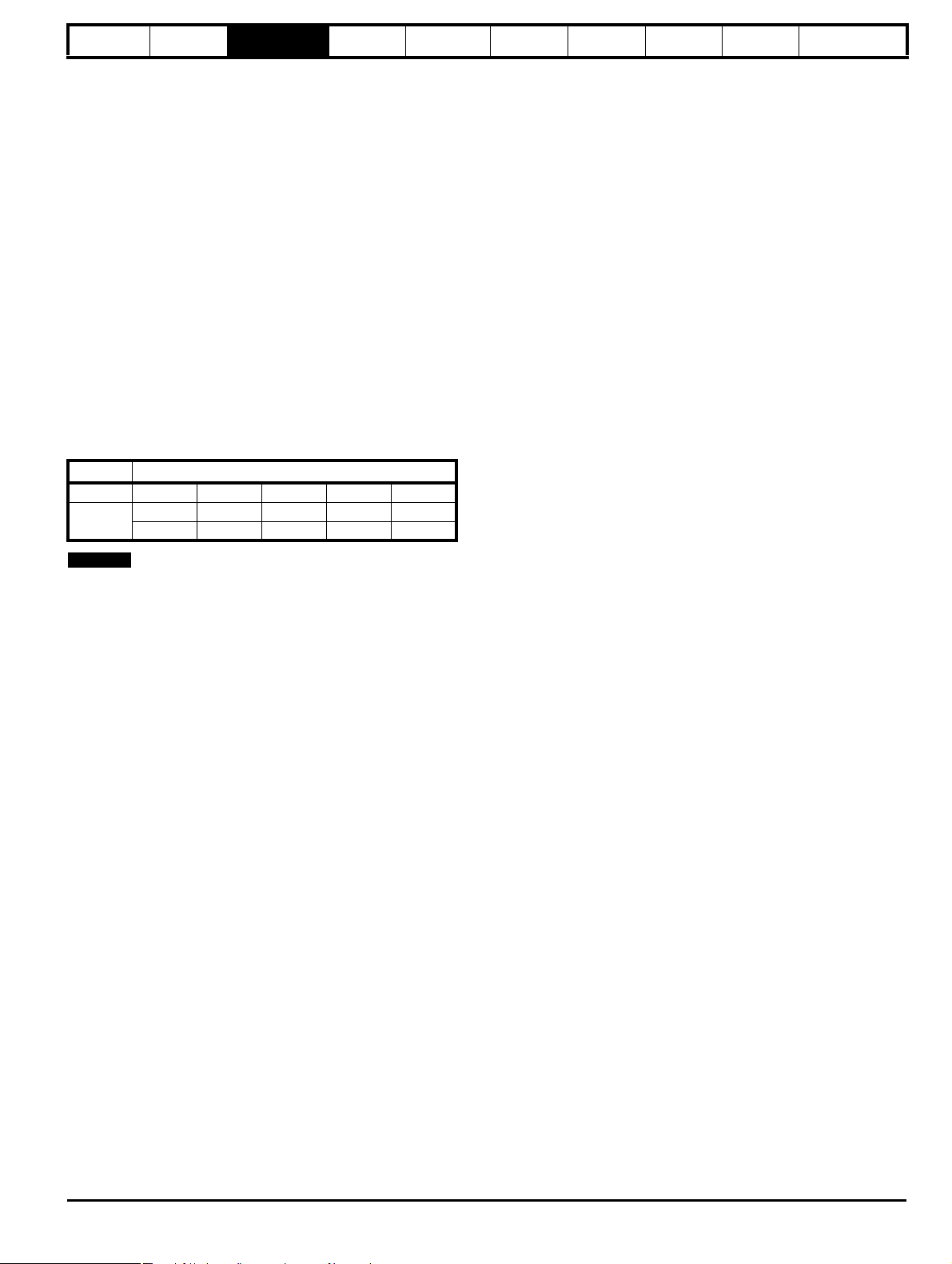
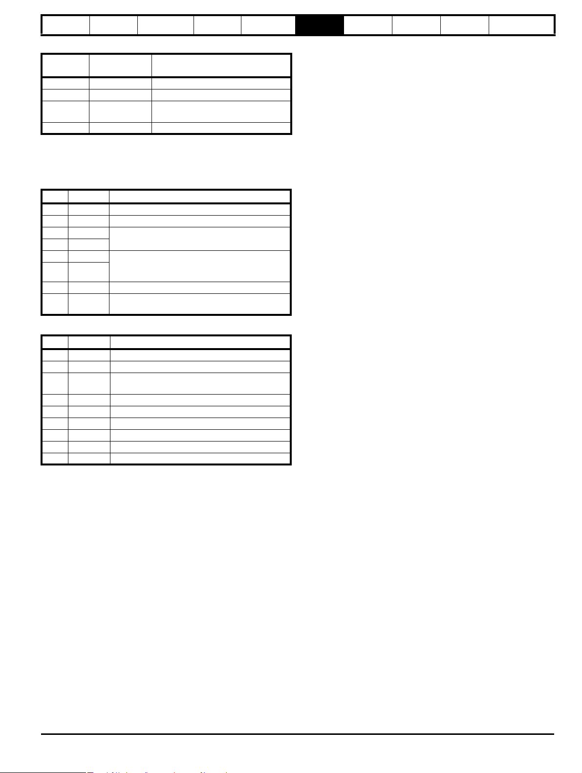
2.3 Eur/USA parameter set differences
The following table gives the differences between the Eur and USA default parameters sets:
Pr Description Eur default USA default Voltage rating
1.06 Maximum set speed 50.0Hz 60.0Hz All
2.08 Standard ramp voltage 750V 775V 400V
2.11 Acceleration rate 5.00/100Hz 33s/100Hz All
2.21 Deceleration rate 10.0s/100Hz 33s/100Hz All
5.06 Motor rated frequency 50.0Hz 60.0Hz All
5.08 Motor rated full load rpm 1500rpm 1800rpm All
5.09 Motor rated voltage 400V 460V 400V
5.14 Voltage mode select Ur I Fd All
5.15 Low frequency voltage boost 3.0% 1.0% All
6.04 Start/Stop logic select 0 4 All
6.12 Enable stop key OFF (0) On (1) All
8.22 Terminal B4 digital input destination Pr 6.29 Pr 6.29 All
8.23 Terminal B5 digital input destination Pr 6.30 Pr 6.34 All
8.24 Terminal B6 digital input destination Pr 6.32 Pr 6.31 All
11.27 Drive configuration AI.AV PAd All
21.01 Motor 2 maximum set speed 50.0Hz 60.0Hz All
21.06 Motor 2 motor rated frequency 50.0Hz 60.0Hz All
21.08 Motor 2 motor rated full load rpm 1500rpm 1800rpm All
21.09 Motor 2 motor rated voltage 400V 460V 400V
Comma nder SK A dvanced User Gui de 5
Issue Number: 9 www.controltechniques.com
Page 6

Introduction
Parameter
x.00
Parameter
description format
Keypad and
display
Serial
communications
CT Modbus
RTU
PLC Ladder
programming
CTSoft
Parameter
x.00
Advanced parameter
descriptions
3 Parameter description format
3.1 Software variable maximum term definitions
Tab le 3- 1
Maximum Definition
FREQ_MAX
[550 Hz]
RATED_CURRENT_MAX
[999.9A]
DRIVE_CURRENT_MAX
[999.9A]
MOTOR1_CURRENT_LIMIT_MAX
[999.9%]
MOTOR2_CURRENT_LIMIT_MAX
[999.9%]
TORQUE_PROD_CURRENT_MAX
[999.9%]
USER_CURRENT_MAX
[999.9%]
AC_VOLTAGE_SET_MAX
[690V]
AC_VOLTAGE_MAX
[886V]
DC_VOLTAGE_SET_MAX
[1150V]
DC_VOLTAGE_MAX
[1190V]
POWER_MAX
[999.9kW]
The values given in square brackets indicate the maximum value allowed for the variable maximum. The term 'rated drive current' is the value used
by the software as rated current, which is not always the same as the drive rating specified in Pr 11.32 (see section 10.5 Menu 4: Current control ).
Maximum frequency reference
FREQ_MAX = Pr 1.06
(If the second motor map is selected Pr 21.01 is used instead of Pr 1.06)
Maximum motor rated current
RATED_CURRENT_MAX ≤ 1.36 x Rated drive current
On drives that offer dual rating, the rated current can be increased above the rated drive current up to a
level not exceeding 1.36 x drive rated current. The actual level varies from one drive size to another.
Maximum drive current
The maximum drive current is the current at the over current trip level and is given by:
DRIVE_CURRENT_MAX = rated drive current x 2
Maximum current limit settings for motor map 1
This maximum current limit setting is the maximum applied to the current limit parameters in motor map
1. See introduction to section 10.5 Menu 4: Current control for the definition.
Maximum current limit settings for motor map 2
This maximum current limit setting is the maximum applied to the current limit parameters in motor map
2. See introduction to section 10.5 Menu 4: Current control for the definition.
Maximum torque producing current
This is used as a maximum for torque and torque producing current parameters. It is
MOTOR1_CURRENT_LIMIT_MAX or MOTOR2_CURRENT_LIMIT_MAX depending on which motor
map is currently active.
Current parameter limit selected by the user
The user can select a maximum for Pr 4.08 (torque reference) and Pr 4.20 (percentage load) to give
suitable scaling for analog I/O with Pr 4.24. This maximum is subject to a limit of
CURRENT_LIMIT_MAX.
USER_CURRENT_MAX = Pr 4.24
Maximum output voltage set-point
Defines the maximum motor voltage that can be selected.
110V drives: 240V
200V drives: 240V
400V drives: 480V
575V drives: 575V
690V drives: 690V
Maximum AC output voltage
This maximum has been chosen to allow for maximum AC voltage that can be produced by the drive
including trapizoidal operation:
AC_VOLTAGE_MAX = 0.7446 x DC_VOLTAGE_MAX
110V drives: 309V
200V drives: 309V
400V drives: 618V
575V drives: 741V
690V drives: 886V
Maximum DC voltage set-point
110V rating drive: 0 to 400V
200V rating drive: 0 to 400V
400V rating drive: 0 to 800V
575V rating drive: 0 to 950V
690V rating drive: 0 to 1150V
Maximum DC bus voltage
The maximum measurable DC bus voltage.
110V drives: 415V
200V drives: 415V
400V drives: 830V
575V drives: 995V
690V drives: 1190V
Maximum power in kW
The maximum power has been chosen to allow for the maximum power that can be output by the drive
with maximum AC output voltage, maximum controlled current and unity power factor. Therefore
POWER_MAX = √3 x AC_VOLTAGE_MAX x RATED_CURRENT_MAX x 2
6 Commander SK Advanced User Guide
www.controltechniques.com Issue Number: 9
Page 7
Introduction
NOTE
Parameter
x.00
Parameter
description format
Keypad and
display
Serial
communications
CT Modbus
RTU
PLC Ladder
programming
CTSoft Menu 0
Advanced parameter
descriptions
3.2 Parameter information
3.2.1 Parameter x.00
Pr x.00 (not Pr 0.00) in every menu is used for storing parameters. The range of this parameter is 4000 and the special codes used are as follows:
1000 Save parameters
1070 Option reset
3.2.2 Parameter types
There are two fundamental types of parameters in the drive, read only (RO) and read/write (RW). The read only parameters cannot be changed by
the user and are there to give the user useful information about the state of the drive. Read/write parameters are for the user to set up the way in
which the drive operates.
Parameters can be further broken down into Bit parameters and Non-bit parameters. Bit parameters are two state only (0 or 1) and if RW are used as
switches or two state input variables to the drive logic, or if RO indicate various drive conditions which are either true (1) or false (0). Non-bit
parameters have more than two values the range of each being given in the following descriptions.
In the basic parameter set, some parameters are represented as strings rather than numeric values which give a more informative indication of the
parameter setting.
Since the parameters in the basic parameter set are copies of extended parameters, the strings are indicated as well as the numeric value. Setting-up
via the serial interface requires numeric data.
Most parameters when being adjusted take immediate effect, but destination and source parameters do not. Using these parameter values while they
are being adjusted could cause a malfunction in the operation of the drive if an intermediary value were taken during the adjustment. For the new
value of one of these parameters to take effect a 'Drive Reset' must be carried out (see section 3.2.4 Drive reset ).
Any changes made to parameters over the serial interface are not stored in the drives EEPROM until a manual store is initiated.
3.2.3 32 bit parameters
Menu 32 bit parameters
Menu 4 Pr 4.01 Pr 4.02 Pr 4.17
Menu 20
Menu 20 parameters cannot be displayed on the drive's LED display. Source and destination parameters cannot be set to 32 bit parameters.
Parameters Pr 4.01, Pr 4.02 and Pr 4.17 are special cases and can be used as a source.All routing within the drive is 16 bit.
If a counter in SyPTLite has a 32 bit output and this output is routed to a drive parameter, for example Pr 1.21, when the count reaches the set range
of Pr 1.21, the value in Pr 1.21 will be frozen until the counter value is reset or falls below the set range.
3.2.4 Drive reset
A drive reset is required for a number of reasons:
• To reset the drive from a tripped state
• To initiate loading of default parameters
• To implement a change in the value of certain parameters
• To initiate the saving of parameters in EEPROM
The later two of these can be done while the drive is running.
The drive can be reset in one of four ways:
1. The drive will be reset with a 0 to 1 transition of the enable input when the drive is tripped, such that a dedicated reset terminal is not required.
2. The drive will be reset when a 0 to 1 transition of the Drive Reset parameter Pr 10.33. This parameter is provided for control by a programmable
digital input such that a terminal can be used to reset the drive.
3. The Stop/Reset key. If the drive is not in keypad mode and the 'always stop' parameter is not set, then the key has a drive reset function only. In
keypad mode or if the 'always stop' parameter is set, a drive reset can be done while the drive is running by holding the Run key while the Stop/
Reset key is activated. When the drive is not running the Stop/Reset key will always reset the drive.
4. By the serial interface. This drive reset is triggered by a value of 100 being written to the User trip parameter Pr 10.38.
3.2.5 Storing drive parameters
When the keypad is used to edit a parameter, the parameter is stored when the mode key is pressed after adjustment has been made.
When using the serial interface, parameters are stored by setting Pr x.00 (not Pr 0.00) to a value of 1000 and performing a 'Drive reset'. Because a
'Drive reset' causes the values of certain parameters to be implemented, storing parameters has the effect of implementing all new values as the
store takes place.
Pr 20.21 Pr 20.22 Pr 20.23 Pr 20.24 Pr 20.25
Pr 20.26 Pr 20.27 Pr 20.28 Pr 20.29 Pr 20.30
Comma nder SK A dvanced User Gui de 7
Issue Number: 9 www.controltechniques.com
Page 8

Introduction
Parameter
x.00
Parameter
description format
Keypad and
display
Serial
communications
CT Modbus
RTU
PLC Ladder
programming
CTSoft
Parameter
x.00
Advanced parameter
descriptions
3.3 Key to parameter codes
In the following sections descriptions are given for the advanced parameter set. With each parameter the following information block is given.
5.11 Number of motor poles
Coding
Range Auto(0), 2P(1), 4P(2), 6P(3), 8P(4)
Default Auto(0)
Second motor
parameter
Update rate Background
The top row gives the menu:parameter number and the parameter name. The other rows give the following information.
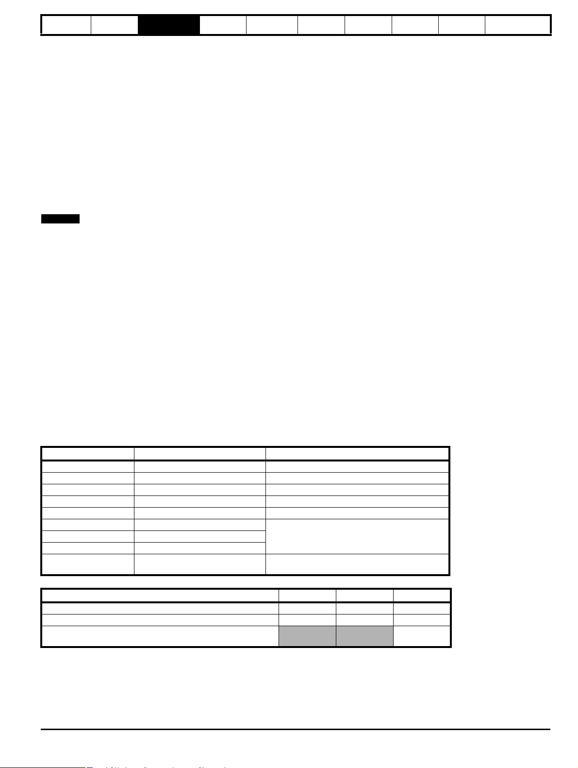
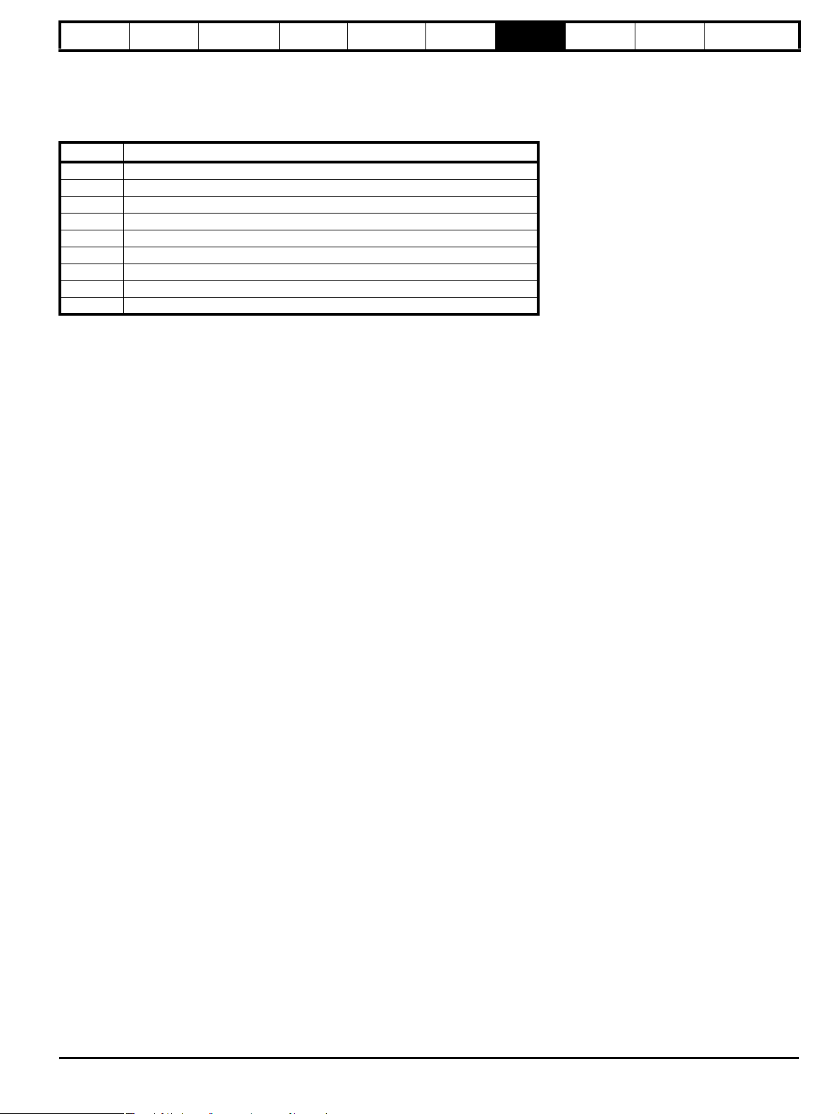
3.3.1 Coding
The coding defines the attributes of the parameter as follows.
Coding Attribute
Bit 1 bit parameter
SP Spare: not used
FI
DE Destination: indicates that this parameter can be a destination parameter.
Txt Text: the parameter uses text strings instead of numbers.
VM Variable maximum: the maximum of this parameter can vary.
DP Decimal place: indicates the number of decimal places used by this parameter.
ND
RA
NC Not copied: not transferred to or from the SmartStick during parameter copying.
NV Not visible: not visible on the keypad.
PT Protected: cannot be used as a destination.
US User save: saved in drive EEPROM when the user initiates a parameter save.
RW Read/write: can be written by the user.
BU
PS Power-down save: automatically saved in drive EEPROM at power-down.
Bit SP FI DE Txt VM DP ND RA NC NV PT US RW BU PS
1 111
Pr 21.11
Filtered: some parameters which can have rapidly changing values are filtered when displayed on the drive keypad for easy
viewing.
No default: when defaults are loaded (except when the drive is manufactured or on EEPROM failure) this parameter is not
modified.
Rating dependant: this parameter is likely to have different values and ranges with drives of different voltage and current ratings.
These parameters are not transferred by the SmartStick when the rating of the destination drive is different from the source drive.
Bit default one/unsigned: Bit parameters with this flag set to one have a default of one (all other bit parameters have a default of
zero. Non-bit parameters are unipolar if this flag is one.
3.3.2 Term definitions
Range
This gives the range of the parameter and the values it can be adjusted to.
Default
The default values given are the standard drive defaults.
Second motor parameter
Some parameters have an equivalent second motor map value that can be used as an alternative when a second motor is selected with Pr 11.4 5.
Menu 21 contains all the second motor map parameters.
Update rate
Defines the rate at which the parameter data is written by the drive or read and acted upon by the drive. Where background update rate is specified,
the update time depends on the drive processor load. Generally the update time is between 10ms and 100ms, however, the update time is
significantly extended when loading defaults, transferring data to/from a SmartStick, or transferring blocks of parameters to/from the drive via the drive
serial communications port.
8 Commander SK Advanced User Guide
www.controltechniques.com Issue Number: 9
Page 9
Introduction
NOTE
Parameter
x.00
Parameter
description format
Keypad and
display
Serial
communications
CT Modbus
RTU
PLC Ladder
programming
CTSoft Menu 0
Advanced parameter
descriptions
3.4 Sources and destinations
3.4.1 Sources
Some functions have source parameters, i.e. drive outputs, PID controller etc. The source parameter range is Pr 0.00 to Pr 21.51.
1. If the source parameter does not exist the input is taken as zero.
2. The input is given by (source value x 100%) / source parameter maximum.
3.4.2 Destinations
Some functions have destination parameters, i.e. drive inputs, etc. The destination parameter range is Pr 0.00 to Pr 21.51.
1. If the destination parameter does not exist then the output value has no effect.
2. If the destination parameter is protected then the output value has no effect.
3. If the function output is a bit value (i.e. a digital input) the destination value is either 0 or 1 depending on the state of the function output. If the
function output is not a bit value (i.e. analog input) the destination value is given by (function output x destination parameter maximum) / 100%
rounded down. Pr 1.36 and Pr 1.37 are a special case. The scaling shown in the description of Pr 1.10 is used when any non-bit type quantity is
routed to these parameters.
4. If more than one destination selector is routed to the same destination, the value of the destination parameter is undefined. The drive checks for
this condition where the destinations are defined in any menu except menu 15. If a conflict occurs a dESt trip occurs that cannot be reset until the
conflict is resolved.
Setting a source or destination parameter to Pr 0.00 will disable the parameter.
3.4.3 Sources and destinations
1. Bit and non-bit parameters may be connected to each other as sources or destinations. The maximum for bit parameters is taken as one.
2. All new source and destination routing only changes to new set-up locations when the drive is reset.
3. When a destination is changed, the old destination is written to zero, unless the destination change is the result of loading defaults or transferring
parameters from a SmartStick. When defaults are loaded the old destination is set to its default value.
4. Cannot select any of the 32 bit parameters.
3.4.4 Parameters actioned on exit of edit mode and on drive reset
Some parameters (Pr 6.04, Pr 11. 27 , Pr 11.4 2, Pr 11.43 and Pr 12.41) are updated on exit from mode or on a drive reset. Serial access to these
parameters must be followed by a reset. Pr 6.04, Pr 11.27 and Pr 12.41 are only actioned on a reset when the value has changed.
3.5 Sample/update times
The sample/update times shown in the control terminal specification within the Commander SK Technical Guide are the default sample/update times
for the default terminal set-up. The sample/update time depends on the destination/source parameter of the digital or analog inputs/outputs.
These sample/update times are the sample or update times for the control microprocessor. The actual sample/update time maybe slightly longer due
to the design of the Commander SK.
3.5.1 Task routine times
At the beginning of each menu, there is a single line parameter description and this contains the update rate for each parameter. This time signifies
the task routine time in the software that the parameter is updated on. For a background task, the time depends on processor loading i.e. what
functions the drive is carrying out and what advanced menus are being used.
Update rate Microprocessor update time Comments
2ms 2ms Updated every 2ms
5ms 5ms Updated every 5ms
21ms 21ms Updated every 21ms
128ms 128ms Updated every 128ms
Reset N/A Destination/source parameter changed on a Reset
B Background
BR Background read
BW Background write
Edit mode exit N/A
From practical tests carried out:
Condition Minimum Maximum Average
Time for drive to respond to a run command 4.1ms 5.62ms 5.02ms
Time for the drive to respond to a stop command 2.82ms 3.94ms 3.31ms
Time for the drive to respond to a step change in analog input
voltage
Updated as a background task. Update rate
depends on processor loading.
Parameter change actioned on exit of edit mode.
Parameter change automation saved.
7.93ms
Comma nder SK A dvanced User Gui de 9
Issue Number: 9 www.controltechniques.com
Page 10
Introduction Parameter x.00
M
M
NOTE
M
STATUS MODE
or
PARAMETER VIEW MODE
Select parameter to view
orPress
Parameter number flashing
PARAMETER EDIT MODE
Change parameter value
orPress
Parameter value flashing
M M
Press and
hold for 2s
M M
Parameters
saved
Press and
release
M
Hold
for 2s
4 mins
timeout
///
M
Parameter
description format
Keypad and
display
Serial
communications
CT Modbus
RTU
PLC Ladder
programming
CTSoft Menu 0
Advanced parameter
descriptions
4 Keypad and display
The keypad and display are used for the following:
• Displaying the operating status of the drive
• Displaying a fault or trip code
• Reading and changing parameter values
• Stopping, starting and resetting the drive
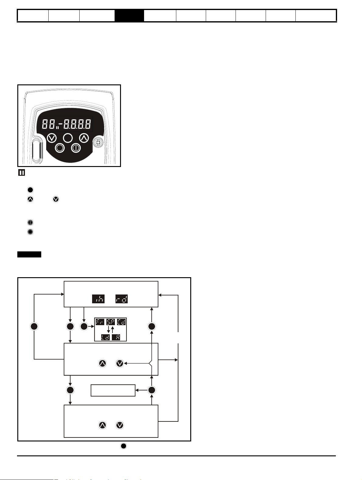
Figure 4-1 Keypad and display
on the display indicates if motor map 1 or 2 is selected.
4.1 Programming keys
The MODE key is used to change the mode of operation of the drive.
The UP and DOWN keys are used to select parameters and edit their values. In keypad mode, they are used to increase and decrease the
speed of the motor.
4.2 Control keys
The START key is used to start the drive in keypad mode.
The STOP/RESET key is used to stop and reset the drive in keypad mode. It can also be used to reset the drive in terminal mode.
4.3 Selecting and changing parameters
This procedure is written from the first power up of the drive and assumes no terminals have been connected, no parameters have been changed and
no security has been set.
Figure 4-2 Keypad control
When in Status mode, pressing and holding the MODE key for 2 seconds will change the display from displaying a speed indication to displaying
10 Commander SK Advanced User Guide
www.controltechniques.com Issue Number: 9
Page 11
Introduction Menu 0
MMM
M
MMMMMMM
M
M
Parameter
description format
Keypad and
display
Serial
communications
CT Modbus
RTU
PLC Ladder
programming
CTSoft
Parameter
x.00
Advanced parameter
descriptions
load indication and vice versa.
Pressing and releasing the MODE key will change the display from status mode to parameter view mode. In parameter view mode, the left hand
display flashes the parameter number and the right hand display shows the value of that parameter.
Pressing and releasing the MODE key again will change the display from parameter view mode to parameter edit mode. In parameter edit mode,
the right hand display flashes the value in the parameter being shown in the left hand display.
Pressing the MODE key in parameter edit mode will return the drive to the parameter view mode. If the MODE key is pressed again then the
drive will return to status mode, but if either of the UP or DOWN keys are pressed to change the parameter being viewed before the MODE
key is pressed, pressing the MODE key will change the display to the parameter edit mode again. This allows the user to very easily change
between parameter view and edit modes while commissioning the drive.
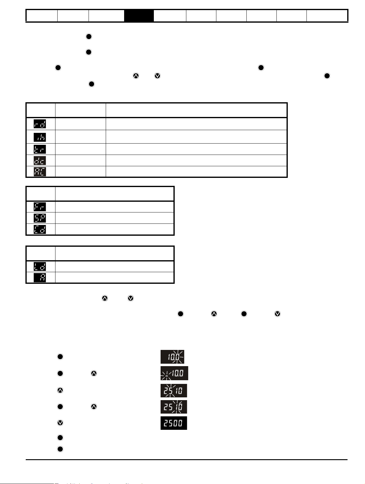
Status Modes
Left hand
display
Status Explanation
Drive ready The drive is enabled and ready for a start command. The output bridge is inactive.
Drive inhibited
The drive is inhibited because there is no enable command, or a coast to stop is in
progress or the drive is inhibited during a trip reset.
Drive has tripped The drive has tripped. The trip code will be displayed in the right hand display.
DC injection braking DC injection braking current is being applied to the motor.
Mains loss When the drive is performing a mains loss stop or ride through.
Speed Indications
Display
Mnemonic
Drive output frequency in Hz
Explanation
Motor speed in rpm
Machine speed in customer define units
Load indications
Display
Mnemonic
Load current as a % of motor rated load current
Drive output current per phase in Amps
The operation of the drives keypad and display is explained in the Commander SK Getting Started Guide.
When in parameter edit mode, the UP and DOWN keys are used to change parameter values. This will increase or decrease the parameter
value by the minimum unit value on display.
To allow values to be changed more quickly, it is possible to press the MODE and UP or the MODE and DOWN keys together to allow
either 1000’s of units, 100’s of units, 10’s of units or units to be adjusted.
Example:
It is required that a deceleration ramp of 2500 seconds is required.
Select Pr 04 using the normal procedure.
• Press the MODE key to enter parameter edit mode
• Press the MODE and UP keys together
• Press the UP key to adjust the 100’s of units
Explanation
• Press the MODE and UP keys together again
• Press the DOWN key once to adjust the 10’s of units
• Press the MODE key to go back to parameter view mode
• Press the MODE key again to go back to status mode
Comma nder SK Adva nced Use r Gu ide 11
Issue Number: 9 www.controltechniques.com
Page 12
Introduction
NOTE
NOTE
Parameter
x.00
Parameter
description format
Keypad and
display
Serial
communications
CT Modbus
RTU
PLC Ladder
programming
CTSoft Menu 0
Advanced parameter
descriptions
5 Serial communications
5.1 Introduction
• 2-wire EIA RS485 via a RJ45 connector
• Modbus RTU protocol supported (see Chapter 6 CT Modbus RTU on page 16 for details).
A serial communications link enables one or more drives to be used in a system controlled by a host controller such as a PLC (Programmable Logic
Controller) or computer. The communications link uses the EIA, also known as RS485, as standard for the hardware interface. The EIA422 (RS422)
hardware interface is also supported.
The Commander SK has a standard 2-wire EIA485 half-duplex interface that enables all drive set-up, operation and monitoring to be accomplished if
required. Therefore it is possible to control the drive entirely through the EIA485 interface without the need for other control cabling etc.
A host controller can operate up to 32 EIA485 devices with the use of one line buffer. Further line buffers will increase this number, if necessary.
Each transmitter/receiver within the Commander SK loads the EIA485 lines by 2 unit loads (with any termination and pull-up and pull-down resistors
disconnected). This means that up to 16 drives can be connected in a single group to one line buffer. When additional line buffers are used, up to
247 drives can be operated by a host controller.
5.2 EIA232 to EIA485 communications
An external EIA232 hardware interface such as a PC can be used with a suitable converter. This converter must have the hardware and software
support to tri-state the transmit buffer following the message transmission. Otherwise, the Commander SK EIA485 transmitter will not be successful
in transmitting a reply as the host transmitter will cause contention on the 2-wire interface.
Examples of EIA232 to EIA485 converters (one to one)
• CT Comms cable (CT part number 4500-0087)
• USB Comms cable (CT part number 4500-0096)
• Amplicon 485Fi
CT Comms cable is specifically designed to convert EIA232 to EIA485 with Control Techniques products.
These converters are for one to one connection between a PC and the Commander SK drive, they do not have multi-drop capability.
The CT Comms cable is an isolated converter. It has reinforced insulation as defined in IEC60950 for altitudes up to 3,000 metres and has been
designed to connect the Commander SK to equipment such as lap-top computers.
5.2.1 CT Comms cable
CT Comms cable enables the use of serial communications with the Commander SK drive using a software package such as CTSoft. This allows
access to all of the drives parameters and advanced function menus.
CT Comms cable is only intended for the purpose of commissioning a drive. Therefore:
• It is not suitable for permanent installation
• It does not provide connectivity to an EIA485 based network
When this converter is used with a Commander SK and a true EIA232 host/master such as a PC, then no external power supply is required. This is
because the converter sources its power from both the drive and the EIA232 port. However, if the converter is attached to a host/master device that
does not have a standard EIA232 port, then an external power supply may be required.
CT Comms cable does not directly use any of the hand shaking functions that are available on a standard EIA232 port, but does utilise 2 of the hand
shaking pins (pins 4 and 7) as a source of power. If these signals are not available, then a +10V supply should be applied to pins 4 and 7 with respect
to pin 5 of the 9-way D-type connector.
Table 5-1 CT Comms cable 9 way D-Type pin functions
EIA232 9-way
D-type connector
1 Not connected
2TX
3RX
4DTR
5GND
6 Not connected
7RTS
8 Not connected
9 Not connected
Pin function
12 Commander SK Advanced User Guide
www.controltechniques.com Issue Number: 9
Page 13

Introduction
NOTE
NOTE
Parameter
x.00
Parameter
description format
Keypad and
display
Serial
communications
CT Modbus
RTU
PLC Ladder
programming
CTSoft Menu 0
Advanced parameter
descriptions
The following table shows the pin functions for the RJ45 connector on the Commander SK control PCB:
Table 5-2 Commander SK RJ45 pin functions
EIA485
RJ45 connector
1
Connection for built in EIA485 termination resistor
(120Ω). Connect to pin 8 if termination is required *
Pin function
2 RXTX (2-wire EIA485 +)
30V
4 +24V (±15%) 100mA supply for options
5 Not connected
6 TX Enable
7 RXTX\ (2-wire EIA485 -)
8
Connection for built in EIA485 termination resistor
(120Ω). Connect to pin 1 if termination is required *
The TX Enable\ is a 0 to +5V output signal from the drive that can be used to control the buffers on an external serial communications converter.
The following table shows the pin functions for the RJ45 connector on the Commander SK Keypad Remote
Table 5-3 Commander SK Keypad Remote RJ45 pin functions
EIA485
RJ45 connector
1
Connection for built in EIA485 termination resistor
(120Ω). Connect to pin 8 if termination is required *
Pin function
2 RXTX (2-wire EIA485 +)
30V
4 +24 supply to keypad
50V
6 Not connected
7 RXTX\ (2-wire EIA485 -)
8
Connection for built in EIA485 termination resistor
(120Ω). Connect to pin 1 if termination is required *
* See Chapter 5.2.3 Terminating resistors on page 14 for information on terminating resistors.
The following table shows the pin functions for the RJ45 connector on the SM-Keypad Plus:
Table 5-4 SM-Keypad Plus RJ45 pin functions
EIA485
RJ45 connector
Pin function
1 Not connected
2 RXTX (2-wire EIA485 +)
30V
4 +24V supply to keypad
50V
6 TX Enable
7 RXTX\ (2-wire EIA485 -)
8 Not connected
When using CT Comms cable, the available baud rate is limited to 19.2kbaud.
5.2.2 Multi-drop converters
Multi-drop converters are available from the following suppliers:
• Amplicon Magic 485F25 or Magic 485F9
(485F25 refers to a 25-way D-type connector and 485F9 refers to a 9-way D-type connector)
www.amplicon.co.uk
E-mail: support@amplicon.co.uk
• Westermo MA44
www.westermo.dircon.co.uk
E-mail: sales@westermo.co.uk
Comma nder SK Adva nced Use r Gu ide 13
Issue Number: 9 www.controltechniques.com
Page 14
Introduction
WARNING
NOTE
NOTE
NOTE
NOTE
NOTE
NOTE
Parameter
x.00
Parameter
description format
Keypad and
display
Serial
communications
CT Modbus
RTU
PLC Ladder
programming
CTSoft Menu 0
Advanced parameter
descriptions
5.2.3 Terminating resistors
When using either of the above converters, or any other suitable converter with Commander SK, it is recommended that no terminating resistors be
connected on to the network. This applies to any of the drives on the network and also any converter used. It may be necessary to disable the
terminating resistor within the converter depending on which type is used. The information on how to disable the terminating resistor will normally be
contained in the user information supplied with the converter. Terminating resistors are of little or no value when used on EIA485 networks operating
at or below 38.4kBaud.
5.2.4 Isolation of the communications port
When using the communications port with a personal computer or centralised controller e.g. PLC, an isolation device must be included
with rated voltage at least equal to the drive supply voltage. Ensure that the correct fuses are installed at the drive input, and that the drive
is connected to the correct supply voltage.
If a serial communications converter other than the CT Comms cable is used to be connected to other circuits classified as Safety Extra
Low Voltage (SELV) (e.g. to a personal computer), a safety isolating barrier must be included to maintain the SELV classification.
5.2.5 Isolation devices
Isolation devices are available from the following suppliers:
• OP232/B1 Isolator
www.scimar.co.uk
E-mail: sales@scimar.co.uk
• 232SPM14 Isolator - 4 channel
• 95POP2 Isolator - 2 channel
www.bb-elec.com
www.bb-europe.com
CT Comms cable is also isolated (CT part number 4500-0087)
For users of Commander SE, the serial link for the Commander SK is identical to that of the Commander SE.
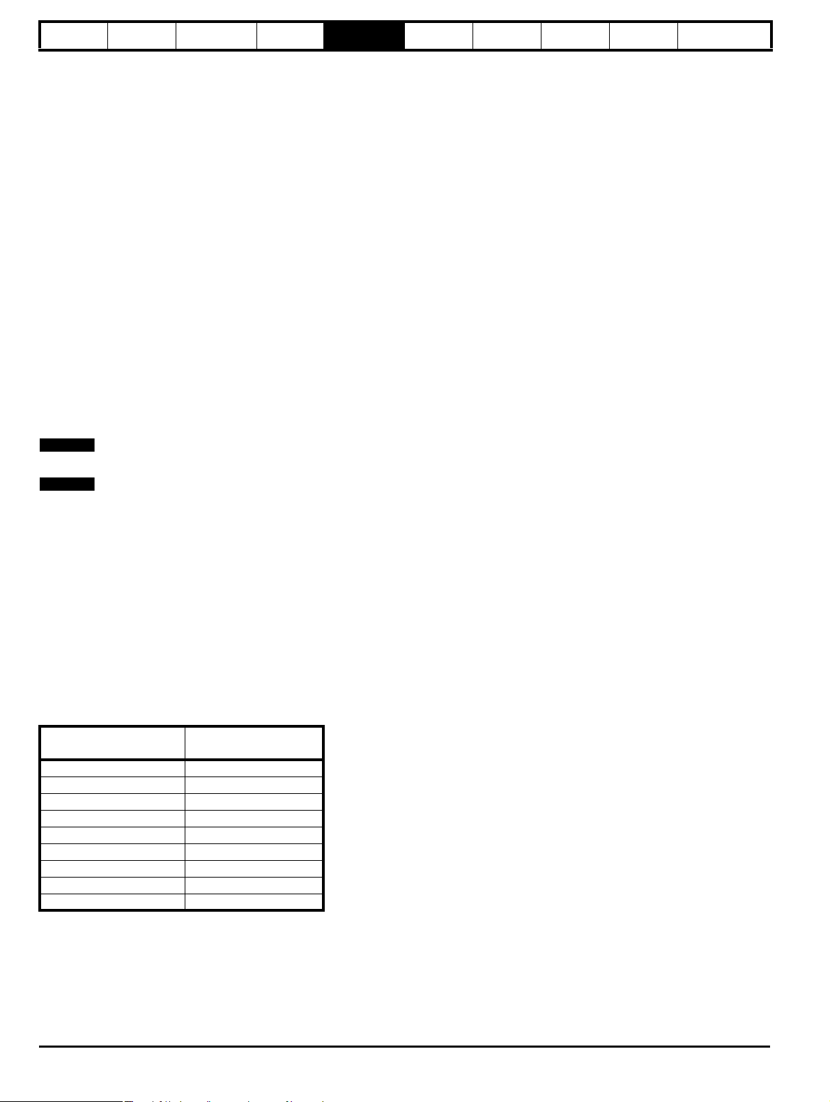
5.3 Serial communications connections
If more than one drive is to be connected to a serial link, make the connections as shown in Figure 5-1. (The network should be a daisy chain
arrangement and not a star arrangement, although short stubs are allowed.)
Pin 4 of the RJ45 connector (+24V) can be connected together through the RJ45 cables, but there is no power sharing mechanism between drives
and therefore the maximum power available is the same as for a single drive. If pin 4 is not linked to the other drives on the network and has an
individual load, then the maximum power (100mA) can be taken from pin 4 of each drive.
The serial communications cable must be shielded. The shields must be connected as shown in Figure 5-1.
A data communications cable should not be run parallel to any power cables, especially ones that connect the drive to motors. If parallel runs are
unavoidable, ensure a minimum spacing of 300mm (12in.) between the communications cable and the power cables.
Cables crossing one another at right-angles are unlikely to give trouble. The maximum cable length for a EIA485 link is 1,200 metres (4,000 feet).
If the serial communications cable is longer than 30 metres (100ft), the following must be adhered to:
• Shielded cable must be used
and either
• Do not connect the drive 0V to ground at the drive
or
• Provide isolation from ground at remote / master communications device
If more than one drive is connected to a host computer/PLC etc. each drive must have an unique serial address (see Pr
number in the permitted range 0 to 247 may be used but addresses with zero in them should not be used as these are used in drive group addressing.
11. 23
on page 139). Any
14 Commander SK Advanced User Guide
www.controltechniques.com Issue Number: 9
Page 15
Introduction
Shielded
connector/splitter
0V
TXRX
TX\RX\
T1
(0V)
Optional
link 2
Serial port
connector
(RJ45)
T1
(0V)
Optional
link 2
Serial port
connector
(RJ45)
Master
communications
device
Commander SK 1 Commander SK 2
Optional link 1
Parameter
x.00
Parameter
description format
Keypad and
display
Figure 5-1 Serial communications connection diagram
Serial
communications
CT Modbus
RTU
PLC Ladder
programming
CTSoft Menu 0
Advanced parameter
descriptions
Cable shown is shielded, 8 core, twisted pair, one to one, RJ45 to RJ45 standard patch cable with shielded RJ45 connectors/splitters.
Optional link 1
Not required if master communications device is galvanically isolated
Optional link 2
In the event of noise problems, it may be helpful to connect the shield of the cable to 0V at the drive.
T-Bar connector/splitter
Unshielded and shielded T-bar connector/splitters are available from the following suppliers:
Unshielded
Part number: CNX3A02KNW
www.insight.com
Part number: 34011
UTP Y adaptor (unshielded twisted pair)
www.lindy.co.uk
RJ45 female to 2 x female
www.dttuk.co.uk/connectors-and-components-modular.htm
Shielded
Part number: 34001
STP Y adaptor (shielded twisted pair)
www.lindy.co.uk
RJ45 connector/splitter (CT part number 3471-0004)
Comma nder SK Adva nced Use r Gu ide 15
Issue Number: 9 www.controltechniques.com
Page 16
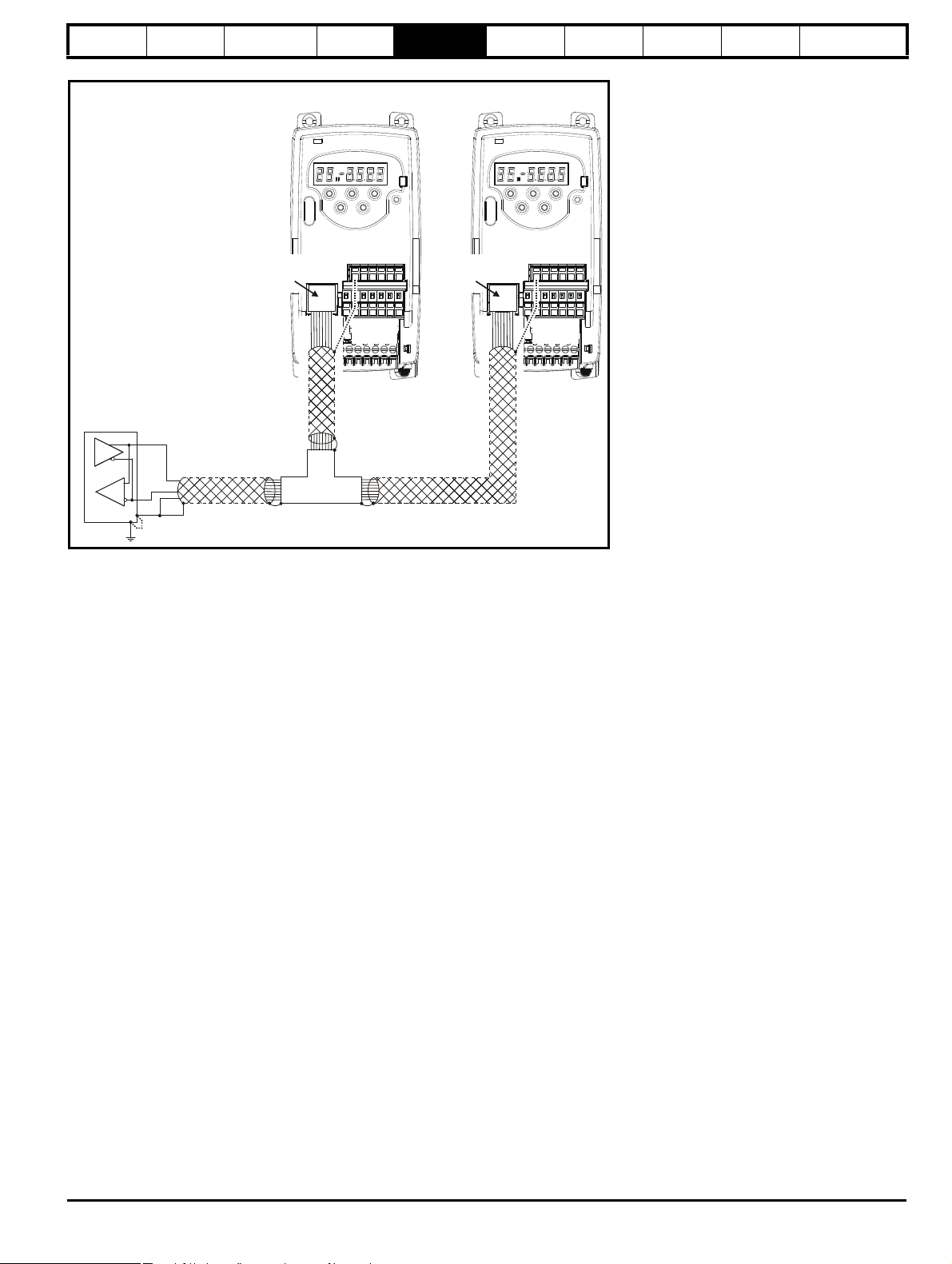
Introduction
Physical layer
UART
RTU framing
Parameter
Database
MODBUS RTU
CMPX.Y
Message data
SLAVE
ADDRESS
16bit CRC
message data
FUNCTION
CODE
Silent
interval
Parameter
x.00
Parameter
description format
Keypad and
display
Serial
communications
CT Modbus
RTU
PLC Ladder
programming
CTSoft Menu 0
Advanced parameter
descriptions
6 CT Modbus RTU
6.1 CT Modbus RTU specification
This section describes the adaptation of the MODBUS RTU protocol offered on Control Techniques' products. The portable software class which
implements this protocol is also defined.
MODBUS RTU is a master slave system with half-duplex message exchange. The Control Techniques (CT) implementation supports the core
function codes to read and write registers. A scheme to map between MODBUS registers and CT parameters is defined. The CT implementation also
defines a 32bit extension to the standard 16bit register data format.
6.1.1 MODBUS RTU
Physical layer
Attribute Description
Normal physical layer for multi-drop operation RS485 2 wire
Bit stream Standard UART asynchronous symbols with Non Return to Zero (NRZ)
Each symbol consists of:-
Symbol
Baud rates 2400,4800, 9600, 19200, 38400
1 start bit
8 data bits (transmitted least significant bit first)
2 stop bits
RTU framing
The frame has the following basic format
The frame is terminated with a minimum silent period of 3.5 character times (for example, at 19200 baud the minimum silent period is 2ms). Nodes
use the terminating silence period to detect the end of frame and begin frame processing. All frames must therefore be transmitted as a continuous
stream without any gaps greater or equal to the silence period. If an erroneous gap is inserted then receiving nodes may start frame processing early
in which case the CRC will fail and the frame will be discarded.
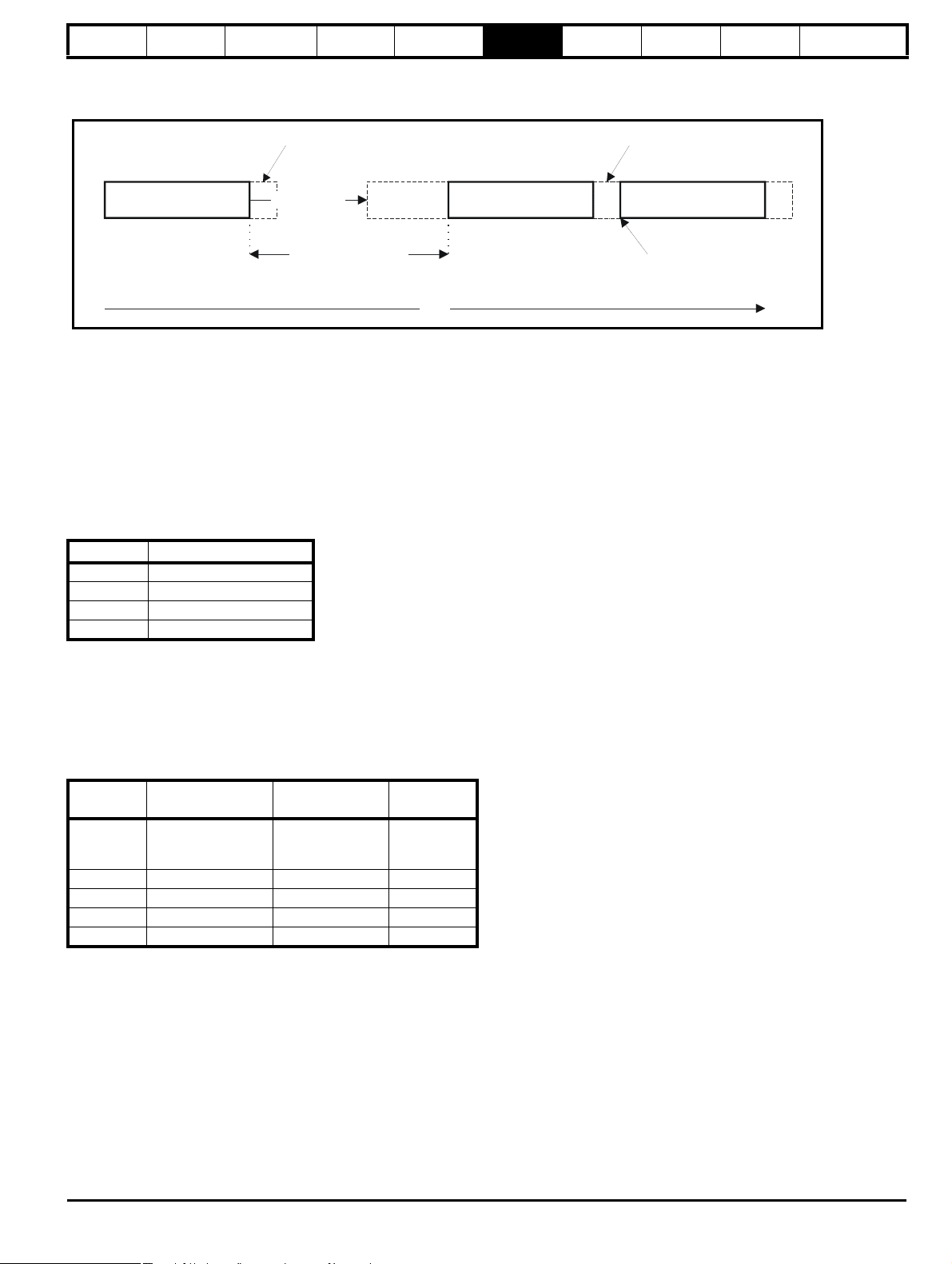
MODBUS RTU is a master slave system. All master requests, except broadcast requests, will lead to a response from an individual slave. The slave
will respond (i.e. start transmitting the response) within the quoted maximum slave response time (this time is quoted in the data sheet for all Control
Techniques products). The minimum slave response time is also quoted but will never be less than the minimum silent period defined by 3.5 character
times.
If the master request was a broadcast request then the master may transmit a new request once the maximum slave response time has expired.
16 Commander SK Advanced User Guide
www.controltechniques.com Issue Number: 9
Page 17
Introduction
Master request
Time
frame detect
Slave frame
processing
Slave response
Slave response time
Master request
New master request
can start here
minimum silence
period
minimum silence
period
Parameter
x.00
Parameter
description format
Keypad and
display
Serial
communications
CT Modbus
RTU
PLC Ladder
programming
CTSoft
Parameter
x.00
Advanced parameter
descriptions
The master must implement a message time out to handle transmission errors. This time out period must be set to the maximum slave response time
+ transmission time for the response.
6.1.2 Slave address
The first byte of the frame is the slave node address. Valid slave node addresses are 1 through 247 decimal. In the master request this byte indicates
the target slave node; in the slave response this byte indicates the address of the slave sending the response.
Global addressing
Address zero addresses all slave nodes on the network. Slave nodes suppress the response messages for broadcast requests.
6.1.3 MODBUS registers
The MODBUS register address range is 16bit (65536 registers) which at the protocol level is represented by indexes 0 through 65535.
PLC registers
Modicon PLCs typically define 4 register 'files' each containing 65536 registers. Traditionally, the registers are referenced 1 through 65536 rather than
0 through 65535. The register address is therefore decremented on the master device before passing to the protocol.
File type Description
1 Read only bits
2 Read / write bits
3 Read only 16bit register
4 Read / write 16bit register
The register file type code is NOT transmitted by MODBUS and all register files can be considered to map onto a single register address space.
All parameters in the drive are holding registers.
CT parameter mapping
All CT products are parameterized using the menu.param notation. Indexes 'menu' and 'param' are in the range 0 through 99. The menu.param is
mapped into the MODBUS register space as menu*100 + param.
To correctly map the parameters at the application layer, the slave device increments the received register address. The consequence of this
behaviour is that Pr 0.00 cannot be accessed.
CT
parameter
MODBUS PLC
register
Register address
(protocol level)
Comments
Pr 0.00
X.Y 40000 + X x 100 + Y X x 100 + Y - 1
cannot be
accessed
Examples:
Pr 1.02 40102 101
Pr 1.00 40100 99
Pr 0.01 40001 0
Data types
The MODBUS protocol specification defines registers as 16bit signed integers. All CT devices support this data size.
Refer to the section 6.1.8 Extended data types on page 20 for detail on accessing 32bit register data.
6.1.4 Data consistency
All CT devices support a minimum data consistency of one parameter (16bit or 32bit data). Some devices support consistency for a complete multiple
register transaction.
Comma nder SK Adva nced Use r Gu ide 17
Issue Number: 9 www.controltechniques.com
Page 18
Introduction
Parameter
x.00
Parameter
description format
Keypad and
display
Serial
communications
CT Modbus
RTU
PLC Ladder
programming
CTSoft Menu 0
Advanced parameter
descriptions
6.1.5 Data encoding
MODBUS RTU uses a 'big-endian' representation for addresses and data items (except the CRC, which is 'little-endian'). This means that when a
numerical quantity larger than a single byte is transmitted, the MOST significant byte is sent first. So for example
16 - bits 0x1234 would be 0x12 0x34
32 - bits 0x12345678L would be 0x12 0x34 0x56 0x78
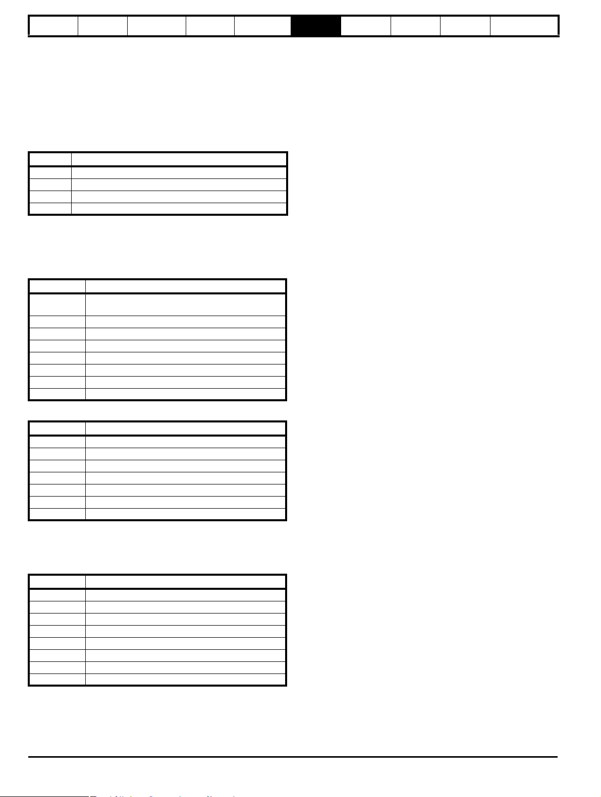
6.1.6 Function codes
The function code determines the context and format of the message data. Bit 7 of the function code is used in the slave response to indicate an
exception.
The following function codes are supported:
Code Description
3 Read multiple 16bit registers
6 Write single register
16 Write multiple 16bit registers
23 Read and write multiple 16bit registers
FC03 Read multiple
Read a contiguous array of registers. The slave imposes an upper limit on the number of registers, which can be read. If this is exceeded the slave
will issue an exception code 2.
Table 6-1 Master request
Byte Description
0
1 Function code 0x03
2 Start register address MSB
3 Start register address LSB
4 Number of 16bit registers MSB
5 Number of 16bit registers LSB
6 CRC LSB
7 CRC MSB
Slave destination node address 1 through 247, 0 is
global
Table 6-2 Slave response
Byte Description
0 Slave source node address
1 Function code 0x03
2 Length of register data in read block (in bytes)
3 Register data 0 MSB
4 Register data 0 LSB
3+byte count CRC LSB
4+byte count CRC MSB
FC6 Write single register
Writes a value to a single 16bit register. The normal response is an echo of the request, returned after the register contents have been written. The
register address can correspond to a 32bit parameter but only 16 bits of data can be sent.
Table 6-3 Master request
Byte Description
0 Slave node address 1 through 247 0 is global
1 Function code 0x6
2 Register address MSB
3 Register address LSB
4 Register data MSB
5 Register data LSB
6 CRC LSB
7 CRC MSB
18 Commander SK Advanced User Guide
www.controltechniques.com Issue Number: 9
Page 19
Introduction
NOTE
Parameter
x.00
Parameter
description format
Keypad and
display
Serial
communications
CT Modbus
RTU
PLC Ladder
programming
CTSoft
Parameter
x.00
Advanced parameter
descriptions
Table 6-4 Slave response
Byte Description
0 Slave source node address
1 Function code 0x6
2 Register address MSB
3 Register address LSB
4 Register data MSB
5 Register data LSB
6 CRC LSB
7 CRC MSB
FC16 Write multiple
Writes a contiguous array of registers. The slave imposes an upper limit on the number of registers which can be written. If this is exceeded the slave
will discard the request and the master will time out.
Table 6-5 Master request
Byte Description
0
1 Function code 0x10
2 Start register address MSB
3 Start register address LSB
4 Number of 16bit registers MSB
5 Number of 16bit registers LSB
6 Length of register data to write (in bytes)
7 Register data 0 MSB
8 Register data 0 LSB
7+byte count CRC LSB
8+byte count CRC MSB
Slave node address 1 through 247
0 is global
Table 6-6 Slave response
Byte Description
0 Slave source node address
1 Function code 0x10
2 Start register address MSB
3 Start register address LSB
4 Number of 16bit registers written MSB
5 Number of 16bit registers written LSB
6 CRC LSB
7 CRC MSB
It is not possible to write to 32 Bit parameters using FC16.
Comma nder SK Adva nced Use r Gu ide 19
Issue Number: 9 www.controltechniques.com
Page 20
Introduction
NOTE
bit 15
TYP1
bits 0 - 13
Type sele ct Parameter address
X x 100+Y-1
bit 14
TYP0
Parameter
x.00
Parameter
description format
Keypad and
display
Serial
communications
CT Modbus
RTU
PLC Ladder
programming
CTSoft Menu 0
Advanced parameter
descriptions
FC23 Read/Write multiple
Writes and reads two contiguous arrays of registers. The slave imposes an upper limit on the number of registers which can be written. If this is
exceeded the slave will discard the request and the master will time out.
Table 6-7 Master request
Byte Description
0
1 Function code 0x17
2 Start register address to read MSB
3 Start register address to read LSB
4 Number of 16bit registers to read MSB
5 Number of 16bit registers to read LSB
6 Start register address to write MSB
7 Start register address to write LSB
8 Number of 16bit registers to write MSB
9 Number of 16bit registers to write LSB
10 Length of register data to write (in bytes)
11 Register data 0 MSB
12 Register data 0 LSB
11+byte count CRC LSB
12+byte
count
Table 6-8 Slave response
Byte Description
0 Slave source node address
1 Function code 0x17
2 Length of register data in read block (in bytes)
3 Register data 0 MSB
4 Register data 0 LSB
3+byte count CRC LSB
4+byte count CRC MSB
Slave node address 1 through 247
0 is global
CRC MSB
6.1.7 Communications timeouts
When a CT Modbus RTU master sends a message to a slave, the master should use a timeout to detect a missing response from a slave. Ideally, a
variable timeout will be used based on the number of hops a CT Modbus RTU message makes between the master and its eventual destination.
In practice a master may not be able to handle variable timeouts in such a fashion. If this is the case a single timeout should be used which is large
enough to cater for the longest route to a destination. The recommended timeouts for use with a specific product are given in the specific product user
guides.
6.1.8 Extended data types
Standard MODBUS registers are 16bit and the standard mapping maps a single X.Y parameter to a single MODBUS register. To support 32bit data
types (integer and float) the MODBUS multiple read and write services are used to transfer a contiguous array of 16bit registers.
Slave devices typically contain a mixed set of 16bit and 32bit registers. To permit the master to select the desired 16bit or 32bit access the top two bits
of the register address are used to indicate the selected data type.
The selection is applied for the whole block access
20 Commander SK Advanced User Guide
www.controltechniques.com Issue Number: 9
Page 21
Introduction
Parameter
x.00
Parameter
description format
Keypad and
display
Serial
communications
CT Modbus
RTU
PLC Ladder
programming
CTSoft
Parameter
x.00
Advanced parameter
descriptions
The 2bit type field selects the data type according to the table below:
Typ e f i eld
bits 15-14
Selected data
type
Comments
00 INT16 backward compatible
01 INT32
10 Float32
IEEE754 standard
Not supported on all slaves
11 Re ser ved
If a 32bit data type is selected then the slave uses two consecutive 16bit MODBUS registers (in 'big endian'). The master must also set the correct
'number of 16bit registers'.
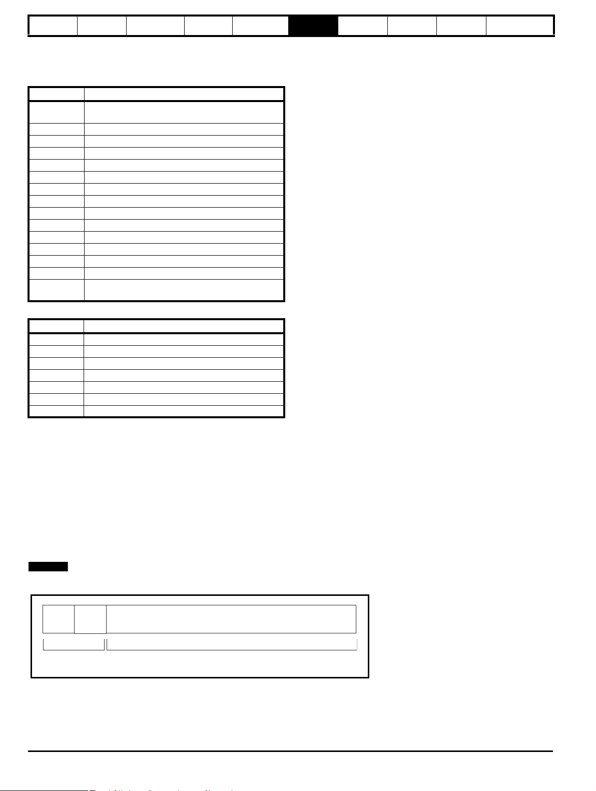
Example, read Pr 20.21 through Pr 20.24 as 32bit parameters using FC03 from node 8:
Table 6-9 Master request
Byte Value Description
0 0x08 Slave destination node address
1 0x03 FC03 multiple read
20x47
30xE4
Start register address Pr 20.21
(0x4000 + 2021 - 1) = 18404 = 0x47E4
4 0x00 Number of 16bit registers to read
50x08
Pr 20.21 through Pr 20.24 is 4x32bit registers =
8x16bit registers
6 CRC LSB
CRC
7
MSB
Table 6-10 Slave response
Byte Value Description
0 0x08 Slave destination node address
1 0x03 FC03 multiple read
20x10
Length of data (bytes) = 4x32bit registers =
16bytes
3-6 Pr 20.21 data
7-10 Pr 20.22 data
11- 14 P r 20.23 data
15-18 Pr 20.24 data
19 CRC LSB
20 CRC MSB
Reads when actual parameter type is different from selected
The slave will send the least significant word of a 32 bit parameter if that parameter is read as part of a 16 bit access.
The slave will sign extent the least significant word if a 16 bit parameter is accessed as a 32 bit parameter. The number of 16 bit registers must be
even during a 32 bit access.
Example, If Pr 20.21 is a 32 bit parameter with a value of 0x12345678, Pr 20.22 is a 16 bit parameter with a value of 0xABCD, and Pr 20.23 is a 16 bit
parameter with a value of 0x0123.
Comma nder SK Adva nced Use r Gu ide 21
Issue Number: 9 www.controltechniques.com
Page 22

Introduction
Parameter
x.00
Parameter
description format
Keypad and
display
Serial
communications
CT Modbus
RTU
PLC Ladder
programming
CTSoft Menu 0
Advanced parameter
descriptions
Number
of 16bit
registers
Response Comments
Read
Start
register
address
Standard 16 bit access
Pr 20.21 2020 1 0x5678
to a 32bit register will
return low 16bit word of
truncated data
Pr 20.21 18404 2 0x12345678 Full 32bit access
Pr 20.21 18404 1 Exception 2
Number of words must
be even for 32bit access
Standard 16 bit access
Pr 20.22 2021 1 0xABCD
to a 32bit register will
return low 16bit word of
data
32bit access to a 16bit
Pr 20.22 18405 2 0xFFFFABCD
register will return 32bit
sign extended data
32bit access to a 16bit
Pr 20.23 18406 2 0x00000123
register will return 32bit
sign extended data
Standard 16 bit access
Pr 20.21 to
Pr 20.22
2020 2
0x5678,
0xABCD
to a 32bit register will
return low 16bit word of
truncated data
Pr 20.21 to
Pr 20.22
18404 4
0x12345678,
0xFFFFABCD
Full 32bit access
Writes when actual parameter type is different from selected
The slave will allow writing a 32 bit value to a 16 bit parameter as long as the 32 bit value is within the normal range of the 16 bit parameter.
The slave will allow a 16 bit write to a 32 bit parameter. The slave will sign extent the written value, therefore, the effective range of this type of write
will be ±32767.
Examples, if Pr 20.21 has a range of ±100000, and Pr 20.22 has a range of ±10000.
Write
Start
register
address
Number
of 16bit
registers
Data Comments
Standard 16 bit write to a
Pr 20.21 2020 1 0x1234
32bit register. Value
written = 0x00001234
Standard 16 bit write to a
Pr 20.21 2020 1 0xABCD
32bit register. Value
written = 0xFFFFABCD
Pr 20.21 18404 2 0x00001234
Value written =
0x00001234
Pr 20.22 2021 1 0x0123 Value written = 0x0123
Pr 20.22 18405 2 0x00000123
Value written =
0x00000123
6.1.9 Exceptions
The slave will respond with an exception response if an error is detected in the master request. If a message is corrupted and the frame is not
received or the CRC fails then the slave will not issue an exception. In this case the master device will time out. If a write multiple (FC16 or FC23)
request exceeds the slave maximum buffer size then the slave will discard the message. No exception will be transmitted in this case and the master
will time out.
Exception message format
The slave exception message has the following format.
Byte Description
0 Slave source node address
1 Original function code with bit7 set
2 Exception code
3CRC LSB
4CRC MSB
22 Commander SK Advanced User Guide
www.controltechniques.com Issue Number: 9
Page 23

Introduction
Parameter
x.00
Parameter
description format
Keypad and
display
Serial
communications
CT Modbus
RTU
PLC Ladder
programming
CTSoft
Parameter
x.00
Advanced parameter
descriptions
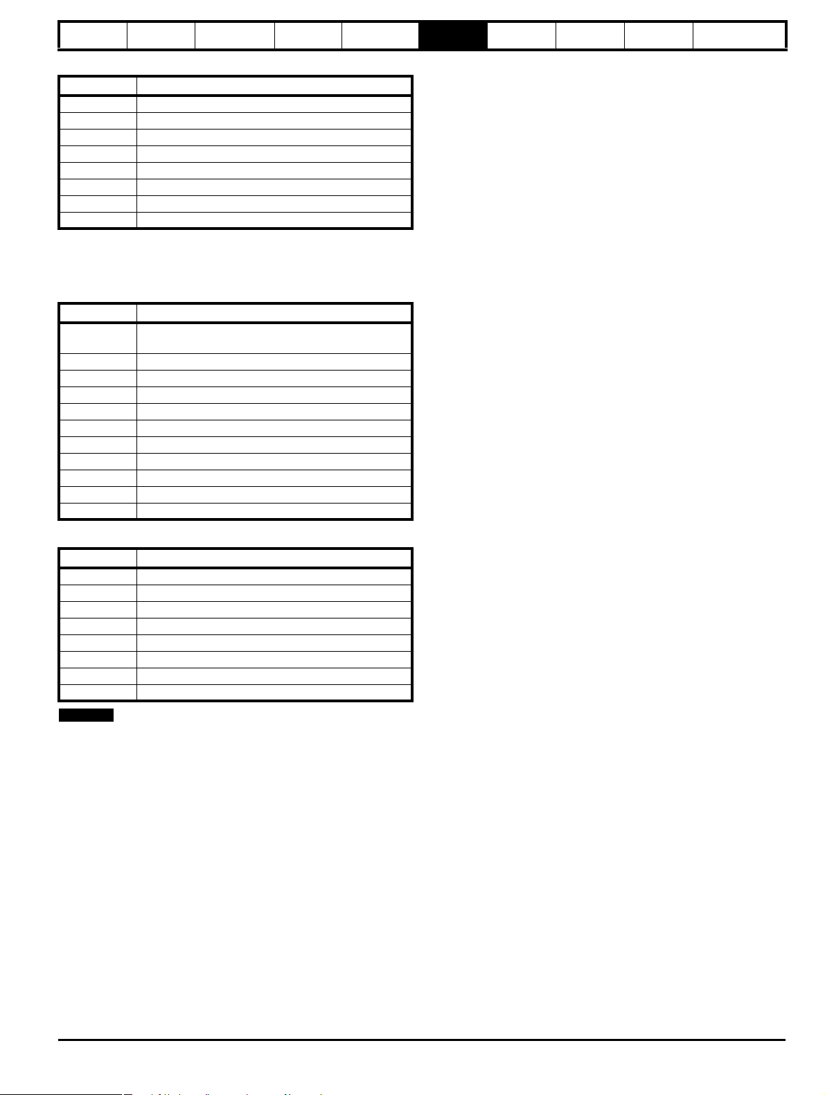
Exception codes
The following exception codes are supported.
Code Description
1 Function code not supported
Register address out of range, or request to read too many
2
registers
Parameter over range during block write FC16
The slave processes the write block in the order the data is received. If a write fails due to an out of range value then the write block is terminated.
However, the slave does not raise an exception response, rather the error condition is signalled to the master by the number of successful writes field
in the response.
Parameter over range during block read/write FC23
There will be no indication that there has been a value out of range during a FC23 access.
6.1.10 CRC
The CRC is a 16bit cyclic redundancy check using the standard CRC-16 polynomial x16 + x15 + x2 + 1. The 16bit CRC is appended to the message
and transmitted LSB first.
The CRC is calculated on ALL the bytes in the frame.
Comma nder SK Adva nced Use r Gu ide 23
Issue Number: 9 www.controltechniques.com
Page 24

Introduction
NOTE
NOTE
NOTE
Parameter
x.00
Parameter
description format
Keypad and
display
Serial
communications
CT Modbus
RTU
PLC Ladder
programming
CTSoft Menu 0
Advanced parameter
descriptions
7 PLC Ladder programming
PLC Ladder programming and SYPTLite
The Commander SK has the ability to store and execute a 3kb PLC ladder logic program.
To enable the Commander SK to store and execute a SYPTLite program, a LogicStick must be installed to the drive.
The ladder logic program is written using SYPTLite, a Windows based ladder diagram editor allowing the development of programs for execution in
the Commander SK.
SYPTLite is designed to be easy to use and to make program development as simple as possible. SYPTLite programs are developed using ladder
logic, a graphical language widely used to program PLCs (IEC 61131-3). SYPTLite allows the user to 'draw' a ladder diagram representing a program.
SYPTLite provides a complete environment for the development of ladder diagrams. Ladder diagrams can be created, compiled into PLC ladder
programs and downloaded into the Commander SK for execution via the RJ45 serial communications port on the front of the drive. The run-time
operation of the compiled ladder diagram on the target can also be monitored using SYPTLite and facilities are provided to interact with the program
on the target by setting new values for target parameters.
SYPTLite is available on the CD which is provided with the drive. The LogicStick can be purchased from your local Control Techniques Drive Centre
or Distributor.
Benefits
The combination of the PLC ladder program and SYPTLite mean that Commander SK can replace nano and some micro PLC’s in many applications.
A Commander SK ladder program can contain up to 50 ladder logic rungs, up to 7 function blocks and 10 contacts per rung. The ladder program will
be stored on the LogicStick.
In addition to the basic ladder symbols, SYPTLIte contains:
• Arithmetic blocks
• Comparison blocks
•Timers
• Counters
• Multiplexers
•Latches
• Bit manipulation
Typical applications of the PLC ladder program include:
• Ancillary pumps
• Fans and control valves
• Interlocking logic
• Sequences routines
• Custom control words
Limitations
The PLC ladder program has the following limitations:
• The maximum program size is 3kbytes including the header and optional source code
• The user cannot create user variables. If they are needed, the user must use free registers in menus 18 and 20. The PLC ladder program can
manipulate any drive parameter except parameters in menu 0.
• The program is only accessible via the drive's RJ45 serial communications port.
• There are no real-time tasks i.e. the scheduling rate of the program cannot be guaranteed. The PLC ladder programming should not be used for
time critical applications.
The LogicStick is rated for 1,000,000 downloads. The LogicStick can be transferred from one drive to another or a fresh copy of a PLC ladder
program can be made on a different LogicStick by downloading the program from SYPTLite.
User program performance
Programs run at a low priority. The Commander SK provides a single background task in which to run the ladder diagram. The drive is prioritised to
perform its major functions first e.g. motor control, and will use any remaining processing time to execute the ladder diagram. As the drive's processor
becomes more heavily loaded running its major functions, less time is spent executing the program. SYPTLite displays the average execution time
calculated over the last 10 scans of the user program.
Getting started and system requirements
SYPTLite can be found on the CD which is supplied with the drive.
• Commander SK LogicStick
• Windows 2000/XP/Vista 32 required. Windows 95/98/98SE/ME/NT4 are not supported.
• Internet explorer V5.0 or later must be installed
• Minimum of 800x600 screen resolution with 256 colors
• 128MB RAM
• Pentium III 500MHz or better recommended
• Adobe Acrobat 5.10 or later (for parameter help)
• RS232 to RS485, RJ45 communications lead to connect the PC to the Commander SK
The user must have administrator rights under Windows 2000/XP/Vista 32 to install the software.
24 Commander SK Advanced User Guide
www.controltechniques.com Issue Number: 9
Page 25
Introduction
Parameter
x.00
Parameter
description format
Keypad and
display
Serial
communications
CT Modbus
RTU
PLC Ladder
programming
CTSoft Menu 0
Advanced parameter
descriptions
To install SYPTLite, insert the CD and the auto-run facility should start the front end screen, from which SYPTLite can be selected.
See the SYPTLite help file for more information regarding using SYPTLite, creating ladder diagrams and the function blocks available.
For the associated PLC ladder program parameters, see parameter Pr 11.47, Pr 11.48 and Pr 11.50 in section 10.12.1 PLC ladder programming on
page 150.
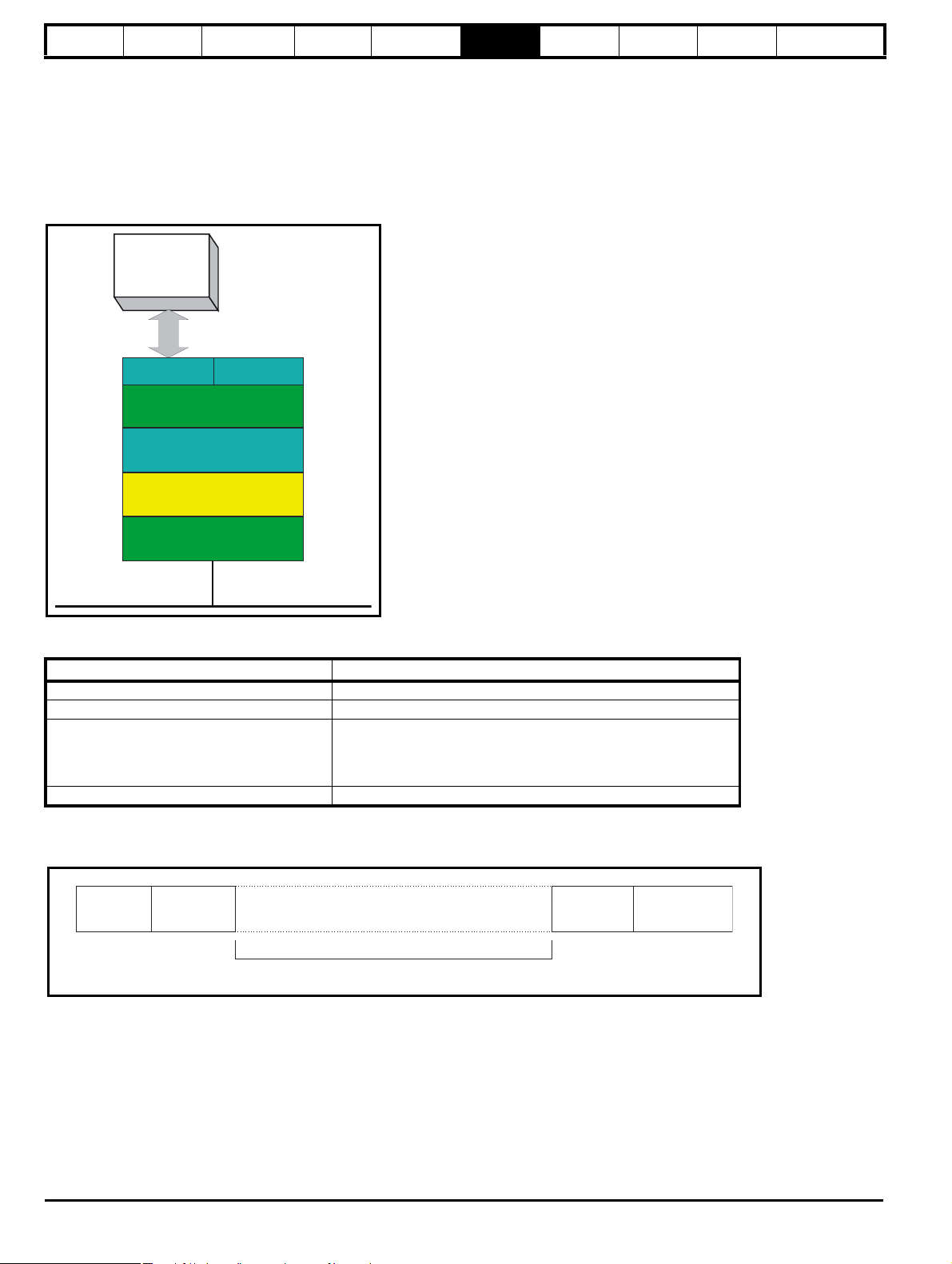
User program trips
Trip Diagnosis
t090 PLC ladder program attempted divide by zero
t091 PLC ladder program attempted access to non-existent parameter
t092 PLC ladder program attempted to write to a read only parameter
t094 PLC ladder program attempted to write a value to parameter which is out of range
t095 PLC ladder program virtual memory stack overflow
t097 PLC ladder program enabled with no LogicStick inserted or LogicStick removed
t096 PLC ladder program invalid operating system call
t098 PLC ladder program invalid instruction
t099 PLC ladder program invalid function block argument
Comma nder SK Adva nced Use r Gu ide 25
Issue Number: 9 www.controltechniques.com
Page 26

Introduction
Parameter
x.00
Parameter
description format
Keypad and
display
Serial
communications
CT Modbus
RTU
PLC Ladder
programming
CTSoft Menu 0
Advanced parameter
descriptions
8 CTSoft
CTSoft is a Windows ™ based software commissioning and monitoring tool for Commander SK and other Control Techniques products.
CTSoft can be used for commissioning and monitoring, drive parameters can be uploaded, downloaded and compared, a simple or custom menu
listing can be created. Drive menus can be displayed in standard list format or as live block diagrams. CTSoft is able to communicate with a single
drive or a network.
CTSoft contains a wizard that can be used for simple drive set up by new or inexperienced users. CTSoft also can also be used to import a
Commander SE Soft ctd file into Commander SK.
CTSoft can be found on the CD supplied with the drive or can be downloaded from www.controltechniques.com.
System requirements
• Pentium IV 1000MHz or better recommended.
• Windows 2000/XP/Vista 32. Windows 95 and 98 are NOT supported.
• Internet Explorer V5.0 or later should also be installed.
• Minimum of 800x600 screen resolution with 256 colors. 1024x768 is recommended.
• Adobe Acrobat 5.1 or later (for parameter help).
• 256MB RAM.
• Administrator rights under Windows 2000/XP/Vista 32 to install and run.
Installing CTSoft
To install CTSoft from the CD, insert the CD and the auto-run facility should start up the front-end screen from which CTSoft can be selected.
Otherwise run the SETUP.EXE in the CTSoft folder. Any previous copy of CTSoft should be uninstalled before proceeding with the installation
(existing projects will not be lost).
Uninstalling CTSoft
To uninstall CTSoft, go to the Control Panel, select "Add and Remove Programs". Scroll down the list until "CTSoft" is found then click on "Change/
Remove". Uninstalling will not lose any user project or data files.
Communications Overview
CTSoft operates in 2 basic communication modes:
In ONLINE mode CTSoft polls the selected drive to update all displayed parameter values. Any changes made to a parameter value will be displayed
within CTSoft.
In OFFLINE mode CTSoft does not require any connection to a drive. Each parameter can be displayed and edited, and these alterations will only
affect CTSoft's internal parameter set.
Getting started with CTSoft
Please refer to the Readme file available within the installation directory for the latest information.
During the startup of CTSoft a number of initialisation files are accessed. These files enable CTSoft to store and retrieve system, user specific and
parameter data.
On initialisation, the startup dialog is displayed allowing you to create a new project, open a previously saved project, or to work with a drive which
automatically creates a project and allows quick access to communicating with a single drive.
Before drive commissioning can proceed, it is necessary to set up the Communications port to enable communication between the host PC and drive.
Select the "Drive" menu, and Properties, to open the Drive Properties dialog.
The document server can be downloaded from www.controltechniques.com. When help on a particular parameter is requested by the user, CTSoft
links to the parameter in the relevant advanced user guide. Double-click the mouse on the required parameter and select parameter help from the
displayed box
The following is a brief introduction to the functions available. Reference should be made to the CTSoft and drive Help files for more detailed
information.
• The drive set-up wizard guides the novice user in entering motor and application data. Help is provided for each step in the set-up wizard and,
after the data is downloaded to the drive, a quick motor test can be performed.
• CTSoft will automatically update the screen with any read values.
• The Navigation Panel allows the user to move between the screens in CTSoft.
• The Terminal Configuration screens display graphically the choice of terminal set-up. They enable the quick and effective setting of parameters to
achieve the terminal configuration desired, with no knowledge of the parameters being set-up. The Analog References screen also provides the
ability to set-up the mode of operation of the analog inputs. The graphical wiring diagram required for basic control dynamical
ly altering with
respect to the user choice.
• The monitoring screens show the status motor parameters displayed on panel meters. Drive faults are displayed and the faults log shows the last
ten trips with description and time.
• The parameter listings are used to display the entire contents of a menu. This allows access to parameters that are not available to the user within
the graphical screens or block diagrams. Complete parameter upload and download functions are provided with the ability to save these to disk.
Complete compare facilities enable the comparison of CTSoft's memory with a user saved parameter file or database defaults, highlighting any
differences.
26 Commander SK Advanced User Guide
www.controltechniques.com Issue Number: 9
Page 27

Introduction
Parameter
x.00
Parameter
description format
Keypad and
display
Serial
communications
CT Modbus
RTU
PLC Ladder
programming
CTSoft Menu 0
Advanced parameter
descriptions
• The Custom list enables parameters to be added to a custom list made up of all available drive parameters. This enables the viewing of unrelated
parameters on the same screen. Custom files may be saved by the user for use at a later date.
• Many of the menus have associated block diagrams that graphically indicate how all of the related parameters interact. To change a parameter
value simply right-click on a parameter and select "Edit Parameter".
Table 8-1 Feature look up table
Feature Parameter number (Pr)
Acceleration rates 2.10 2.11 to 2.19 2.30 2.32 2.33 2.34 2.39
Allow negative
references
1.10
Analog I/O Menu 7
Analog output 7.19 7.20 7.33
Analog speed
reference 1
Analog speed
reference 2
1.36 7.01 7.06 7.08 7.09 7.10 7.28 7.30
1.37 7.02 7.11 7.12 7.13 7.14 7.31 1.41
Application menus Menu 18 Menu 20
At speed indicator bit 3.06 10.05 10.06 10.07
Auto reset 10.34 10.35 10.36 10.01
Autotune 5.12 5.17 5.23 5.24 5.10 5.11
Binary sum 9.29 9.30 9.31 9.32 9.33 9.34
Brake control 12.40 to 12.47
Braking 10.11 10.10 10.30 10.31 6.01 2.04 10.12 10.39 10.40
Catch a spinning motor 6.09 5.12 5.17
Copying 11.42
Coast to stop 6.01
Comms 11.23 to 11.26 6.42 6.43
Cost - per kWh
electricity
6.16 6.17 6.24 6.25 6.26
Current controller 4.13 4.14
Current feedback 4.01 4.02 4.17 4.04 4.20 4.24 4.26 10.08 10.09 10.17
Current limits 4.07 4.18 4.15 4.16 4.19 5.07 5.10 10.08 10.09 10.17
Current rating 11.32 4.24
DC bus voltage 5.05 2.08
DC injection braking 6.01 6.06 6.07
Deceleration rates 2.20 2.21 to 2.29 2.31 2.35 2.36 2.37 2.39
Defaults 11.43 11.46
Digital I/O Menu 8
Digital I/O read word 8.20
Digital I/O B3 8.01 8.11 8.21 8.31 8.41 12.41 Menu 3
Digital Input B4 8.02 8.12 8.22 6.04
Digital Input B5 8.03 8.13 8.23 6.04
Digital input B6 8.04 8.14 8.24 6.04
Digital input B7 8.05 8.15 8.25 8.35 Menu 3
Direction 1.12 10.13 10.14 6.30 6.31 6.32 6.33 6.37 10.40
Display units 4.21 5.34
Display timeout 11.41
Drive active 1.11 10.02 10.40
Drive ok 10.01 10.36 10.40
Dynamic V/F 5.13
Enable 6.15 6.29 8.02 8.12 8.22
External trip 10.32
Fan speed 6.45
Frequency input 3.32 3.33 3.34 3.43 3.44 3.45 8.25
Frequency output 3.17 3.18 8.21
Frequency reference
selection
1.14 1.15
Hard speed reference 3.22 3.23
High stability space
vector modulation
5.19
Comma nder SK Adva nced Use r Gu ide 27
Issue Number: 9 www.controltechniques.com
Page 28

Introduction
Parameter
x.00
Parameter
description format
Keypad and
display
Serial
communications
CT Modbus
RTU
PLC Ladder
programming
CTSoft Menu 0
Advanced parameter
descriptions
Table 8-1 Feature look up table
Feature Parameter number (Pr)
I/O sequencer 6.04 6.30 6.31 6.32 6.33 6.34 6.39 6.40 6.42 6.43
Jog reference 1.05 1.13 2.19 2.29
Keypad reference 1.17 1.14 1.43 1.51 6.12
Limit switches 6.35 6.36
Logic function 1 9.01 9.04 9.05 9.06 9.07 9.08 9.09 9.10
Logic function 2 9.02 9.14 9.15 9.16 9.07 9.18 9.19 9.20
Low DC bus operation 6.10
Mains loss 6.03 10.15 5.05
Maximum speed 1.06
Menu 0 set up 11.01 to 11.10 11.27 6.04
Minimum speed 1.07 10.04
Motor map 5.06 5.07 5.08 5.09 5.10 5.11
Motor map 2 Menu 21 11.45
Motorized
potentiometer
9.03 9.21 9.22 9.23 9.24 9.25 9.26 9.27 9.28
Offset speed reference 1.04 1.38 1.09
Onboard PLC 11.47 11.48 11.50
Open loop vector mode 5.14 5.17 5.23
Operating mode 5.14
Output 5.01 5.02 5.03 5.04
Over modulation enable 5.20
PID controller Menu 14
Power up parameter 11.22 11.21
Precision reference 1.18 1.19 1.20 1.44
Preset speeds 1.15 1.21 to 1.28 1.14 1.42 1.45 1.46 1.47 1.48 1.50
Programmable logic Menu 9
PWM output 3.17 8.21
Ramp (accel / decel)
mode
2.04 2.08 6.01 2.03 10.30 10.31 10.39
Regenerating 10.10 10.11 10.30 10.31 6.01 2.04 10.12 10.39 10.40
Relay output 8.07 8.17 8.27 12.41
Reset 10.33 8.02 8.12 8.22 6.14
S ramp 2.06 2.07
Security code 11.30 11.44 5.50
Serial comms 11.23 to 11.26 6.42 6.43
Skip speeds 1.29 1.30 1.31 1.32 1.33 1.34 1.35
Slip compensation 5.08 5.27
Software version 11.29 11.34 11.35
Speed reference
selection
1.14 1.15 1.49 1.50 1.01 1.02
Status word 10.40
Supply 5.05
Switching frequency 5.18 5.35 5.37
Thermal protection drive
Thermal protection motor
5.18 5.35 7.04 7.05 7.34 7.35 7.36 10.18
4.15 5.07 4.19 4.16 4.25
Thermistor input 8.35
Threshold detector 1 12.01 12.03 12.04 12.05 12.06 12.07
Threshold detector 2 12.02 12.23 12.24 12.25 12.26 12.27
Time - run log 6.22 6.23
Torque mode 4.08 4.11
Trip detection 10.37
10.20 to
10.29
Trip log 10.20 to 10.29
User trip 10.38
Under voltage 5.05 10.15
28 Commander SK Advanced User Guide
www.controltechniques.com Issue Number: 9
Page 29

Introduction
Parameter
x.00
Parameter
description format
Keypad and
display
Serial
communications
CT Modbus
RTU
PLC Ladder
programming
CTSoft Menu 0
Table 8-1 Feature look up table
Feature Parameter number (Pr)
V/F mode 5.14 5.15
Variable selector 1 12.08 12.09 12.10 12.11 12.12 12.13 12.14 12.15
Variable selector 2 12.28 12.29 12.30 12.31 12.32 12.33 12.34 12.35
Voltage mode 5.14 5.17 5.23 5.15
Voltage rating 11.33 5.09 5.05
Warning 10.19 10.12 10.17 10.18 10.40
Zero speed indicator bit 3.05 10.03
Advanced parameter
descriptions
Comma nder SK Adva nced Use r Gu ide 29
Issue Number: 9 www.controltechniques.com
Page 30
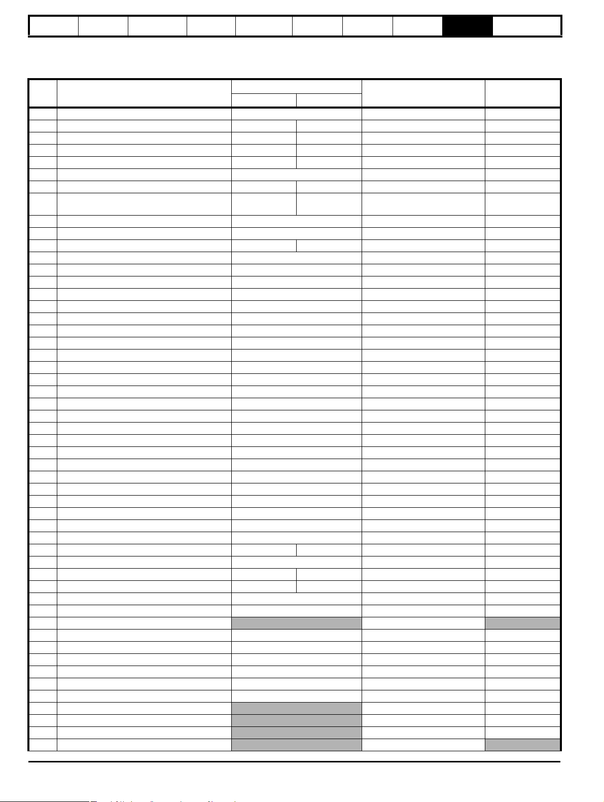
Introduction
Parameter
x.00
Parameter
description format
Keypad and
display
Serial
communications
CT Modbus
RTU
PLC Ladder
programming
CTSoft
9 Menu 0
Table 9-1 Menu 0 parameters: single line descriptions
Par Description
Default
Eur USA
01 Minimum set speed (Hz) 0.0 Pr 1.07
02 Maximum set speed (Hz) 50.0 60.0 Pr 1.06
03 Acceleration rate (s/100Hz) 5.0 33.0 Pr 2.11
04 Deceleration rate (s/100Hz) 10.0 33.0 Pr 2.21
05 Drive configuration AI.AV PAd Pr 11.27
06 Motor rated current (A) Drive rating Pr 5.07
07 Motor rated speed (rpm) 1500 1800 Pr 5.08
08 Motor rated voltage (V)
230/400/575/
690
230/460/575/
690
09 Motor power factor (cos ϕ)0.85Pr 5.10
10 Parameter access L1 Pr 11.44
11 Start/Stop logic select 0 4 Pr 6.04
12 Brake controller enable diS Pr 12.41
15 Jog reference (Hz) 1.5 Pr 1.05
16 Analog input 1 mode (mA) 4-.20 Pr 7.06
17 Enable negative preset speeds OFF (0) Pr 1.10
18 Preset speed 1 (Hz) 0.0 Pr 1.21
19 Preset speed 2 (Hz) 0.0 Pr 1.22
20 Preset speed 3 (Hz) 0.0 Pr 1.23
21 Preset speed 4 (Hz) 0.0 Pr 1.24
22 Load display units Ld Pr 4.21
23 Speed display units Fr Pr 5.34
24 Customer defined scaling 1.000 Pr 11.21
25 User security code 0 Pr 11.3 0
27 Power up keypad reference 0 Pr 1.51
28 Parameter copying no Pr 11.42
29 Load defaults no Pr 11 .43
30 Ramp mode select 1 Pr 2.04
31 Stop mode select 1 Pr 6.01
32 Dynamic V to f select OFF (0) Pr 5.13
33 Catch a spinning motor select 0 Pr 6.09
34 Terminal B7 mode select dig Pr 8.35
35 Digital output control (terminal B3) n=0 Pr 8.41
36 Analog output control (terminal B1) Fr Pr 7.33
37 Maximum switching frequency (kHz) 3 Pr 5.18
38 Autotune 0 Pr 5.12
39 Motor rated frequency (Hz) 50.0 60.0 Pr 5.06
40 Number of motor poles Auto Pr 5.11
41 Voltage mode select Ur I Fd Pr 5.14
42 Low frequency voltage boost (%) 3.0 1.0 Pr 5.15
43 Serial comms baud rate 19.2 Pr 11.25
44 Serial comms address 1 Pr 11.23
45 Software version
46 Brake release current threshold (%) 50 Pr 12.42
47 Brake apply current threshold (%) 10 Pr 12.43
48 Brake release frequency (Hz) 1.0 Pr 12.44
49 Brake apply frequency (Hz) 2.0 Pr 12.45
50 Pre-brake release delay (s) 1.0 Pr 12.46
51 Post brake release delay (s) 1.0 Pr 12.47
52 *Solutions Module dependant
53 *Solutions Module dependant
54 *Solutions Module dependant
55 Last trip
Corresponding extended
menu parameter
Pr 5.09
Pr 11.29
Pr 15.03
Pr 15.04
Pr 15.06
Pr 10.20
Menu 0
Advanced parameter
descriptions
Setting
30 Commander SK Advanced User Guide
www.controltechniques.com Issue Number: 9
Page 31

Introduction
Parameter
x.00
Parameter
description format
Keypad and
display
Serial
communications
CT Modbus
RTU
PLC Ladder
programming
CTSoft
Menu 0
Advanced parameter
descriptions
Par Description
56 Trip before Pr 55
Default
Eur USA
Corresponding extended
menu parameter
Pr 10.21
57 Trip before Pr 56 Pr 10.22
58 Trip before Pr 57 Pr 10.23
59 PLC ladder program enable 0 Pr 11.4 7
60 PLC ladder program status
Pr 11.48
61 Configurable parameter 1
62 Configurable parameter 2
63 Configurable parameter 3
64 Configurable parameter 4
65 Configurable parameter 5
66 Configurable parameter 6
67 Configurable parameter 7
68 Configurable parameter 8
69 Configurable parameter 9
70 Configurable parameter 10
71 Pr 61 set up parameter Pr 11.01
72 Pr 62 set up parameter
73 Pr 63 set up parameter
74 Pr 64 set up parameter
75 Pr 65 set up parameter
76 Pr 66 set up parameter
77 Pr 67 set up parameter
78 Pr 68 set up parameter
79 Pr 69 set up parameter
80 Pr 70 set up parameter
81 Frequency reference selected
Pr 11.02
Pr 11.03
Pr 11.04
Pr 11.05
Pr 11.06
Pr 11.07
Pr 11.08
Pr 11.09
Pr 11.10
Pr 1.01
82 Pre-ramp reference Pr 1.03
83 Post-ramp reference Pr 2.01
84 DC Bus voltage Pr 5.05
85 Motor frequency Pr 5.14
86 Motor voltage Pr 5.02
87 Motor speed Pr 5.04
88 Motor current Pr 4.01
Read only diagnostic parameters
89 Motor active current Pr 4.02
90 Digital I/O read word Pr 8.20
91 Reference enabled indicator Pr 1.11
92 Reverse selected indicator Pr 1.12
93 Jog selected indicator Pr 1.13
94 Analog input 1 level Pr 7.01
95 Analog input 2 level Pr 7.02
* Please refer to the appropriate Solutions Module manual.
Setting
Comma nder SK Adva nced Use r Gu ide 31
Issue Number: 9 www.controltechniques.com
Page 32

Introduction
Analog inputs
94
95
81
Analog input 1 (%)
Analog input 2 (%)
Digital I/O
XX
Digital I/O
Read
word
Pr
90
Sequencer
92
93
91
Jog
selected
Reverse
selected
Reference
on
1
0
0
1
0
1
0Hz
82
Pre-ramp
reference (Hz)
84
DC bus
voltage
42
41
40
39
38
37
32
09
08
07
06
Motor rated
current
Motor rated
speed
Motor rated
voltage
Motor power
factor
Variable torque
select
Switching
frequency
Autotune
Motor rated
frequency
No. of poles
Volt age
mode select
Volt age
boost
Motor control
03
Acceleration
rate
Deceleration
rate
Ramps
02
01
Minimum
speed
Maximum
speed
Speed clamps
83
Post-ramp
reference
(Hz)
85
Motor
frequency
86
Motor
voltage87Motor
speed
rpm
8889Motor active
current
Motor current
Current
measurement
15
Jog
reference
Digital I/O read word Pr
90
Terminal Binary value for XX
B3 1
B4 2
B5 4
B6 8
B7 16
T5/T6 64
Reference
selected (Hz)
04
T2
T4
T6
T5
B3
B4
B5
B6
B7
XX
XX
Key
Read-write
(RW)
parameter
Read-only (RO)
parameter
Input
terminals
Output
terminals
XX
XX
11
12
Start/stop
logic select
Brake
enable
31
Stopping
mode
Ramp mode
30
0
1
16
Analog 1
input
mode
35
Digital output
function
34
Mode select
33
Catch a
spinning
motor
select
X-1
29
28
27
25
24
23
22
18 to 21
17
10
Parameter
access
Enable negative
preset speeds
Preset speeds
Load display
units
Speed display
units
Customer
defined scaling
Security access
Power-up
keypad reference
Parameter
cloning
Parameter
default
Other parameters
B1
36
Analog
output
function
Analog
output
B7
Parameter
x.00
Parameter
description format
Figure 9-1 Menu 0 logic diagram
Keypad and
display
Serial
communications
CT Modbus
RTU
PLC Ladder
programming
CTSoft
Menu 0
Advanced parameter
descriptions
32 Commander SK Advanced User Guide
www.controltechniques.com Issue Number: 9
Page 33

Introduction
Parameter
x.00
Parameter
description format
Keypad and
display
Serial
communications
CT Modbus
RTU
10 Advanced parameter descriptions
10.1 Overview
Table 10-1 Menu descriptions
Menu no. Description
1 Frequency / speed reference
2Ramps
3 Frequency I/O, speed feedback and speed control
4 Current control
5 Motor control
6 Sequencer and clock
7 Analog I/O
8 Digital I/O
9 Programmable logic, motorized pot and binary sum
10 Status and diagnostics
11 General drive set-up
12 Threshold detectors and variable selectors
14 User PID controller
15* Solutions module parameters
18 Application menu 1
20 Application menu 2
21 Second motor parameters
*Only appears when a solutions module is installed to the Commander SK.
Table 10-2 gives a full key of the coding which appears in the following parameter tables.
Table 10-2 Key to parameter coding
Coding Attribute
Bit 1 bit parameter
SP Spare: not used
Filtered: some parameters which can have rapidly changing
FI
values are filtered when displayed on the drive keypad for
easy viewing.
Destination: indicates that this parameter can be a
DE
destination parameter.
Txt Text: the parameter uses text strings instead of numbers.
VM Variable maximum: the maximum of this parameter can vary.
Decimal place: indicates the number of decimal places used
DP
by this parameter.
No default: when defaults are loaded (except when the drive
ND
is manufactured or on EEPROM failure) this parameter is not
modified.
Rating dependant: this parameter is likely to have different
values and ranges with drives of different voltage and current
ratings. These parameters are not transferred by SmartStick
RA
when the rating of the destination drive is different from the
source drive.
Not copied: not transferred to or from SmartStick during
NC
copying.
NV Not visible: not visible on the keypad.
PT Protected: cannot be used as a destination.
User save: saved in drive EEPROM when the user initiates a
US
parameter save.
RW Read/write: can be written by the user.
Bit default one/unsigned: Bit parameters with this flag set to
one have a default of one (all other bit parameters have a
BU
default of zero. Non-bit parameters are unipolar if this flag is
one.
Power-down save: automatically saved in drive EEPROM at
PS
power-down.
PLC Ladder
programming
CTSoft Menu 0
Advanced parameter
descriptions
Comma nder SK Adva nced Use r Gu ide 33
Issue Number: 9 www.controltechniques.com
Page 34

Menu 1 Introduction
Parameter
x.00
Parameter
description format
Keypad and
display
Serial
communications
CT Modbus
RTU
PLC Ladder
programming
CTSoft Menu 0
Advanced parameter
descriptions
10.2 Menu 1: Speed reference selection, limits and filters
Table 10-3 Menu 1 parameters: single line descriptions
Parameter Range Default Setting Update Rate
1.01 Frequency reference selected {81} ± 550 Hz*
1.02 Pre-skip filter reference ± 550 Hz
1.03 Pre-ramp reference {82} ± 550 Hz
1.04 Reference offset ± 550 Hz 0.0 5 ms
1.05 Jog reference {15} 0.0 to 400.0 Hz 1.5 5 ms
1.06 Maximum set speed {02} 0.0 to 550 Hz
1.07 Minimum set speed {01} 0.0 to Pr 1.06 0.0 B
1.08 Not used
1.09 Reference offset select OFF(0) or On(1) OFF(0) 5 ms
1.10 Allow negative references {17} OFF(0) or On(1) OFF(0) B
1.11 Reference enabled indicator {91} OFF(0) or On(1)
1.12 Reverse selected indicator {92} OFF(0) or On(1)
1.13 Jog selected indicator {93} OFF(0) or On(1)
A1.A2(0), A1.Pr(1),
1.14 Reference selector
A2.Pr(2), Pr(3), PAd(4),
Prc(5)
1.15 Preset speed selector 0 to 8 0 5 ms
1.16 Not used
1.17 Keypad reference ± 550 Hz 0.0 B
1.18 Precision reference coarse ± 550 Hz 0.0 B
1.19 Precision reference fine 0.000 to 0.099 Hz 0.000 B
1.20 Precision reference update disable OFF(0) or On(1) OFF(0) 5 ms
1.21 Preset speed 1 {18} ± 550 Hz 0.0 5 ms
1.22 Preset speed 2 {19} ± 550 Hz 0.0 5 ms
1.23 Preset speed 3 {20} ± 550 Hz 0.0 5 ms
1.24 Preset speed 4 {21} ± 550 Hz 0.0 5 ms
1.25 Preset speed 5 ± 550 Hz 0.0 5 ms
1.26 Preset speed 6 ± 550 Hz 0.0 5 ms
1.27 Preset speed 7 ± 550 Hz 0.0 5 ms
1.28 Preset speed 8 ± 550 Hz 0.0 5 ms
1.29 Skip reference 1 0.0 to 550 Hz 0.0 B
1.30 Skip reference band 1 0.0 to 25 Hz 0.5 B
1.31 Skip reference 2 0.0 to 550 Hz 0.0 B
1.32 Skip reference band 2 0.0 to 25 Hz 0.5 B
1.33 Skip reference 3 0.0 to 550 Hz 0.0 B
1.34 Skip reference band 3 0.0 to 25 Hz 0.5 B
1.35 Reference in rejection zone OFF(0) or On(1)
1.36 Analog reference 1 ± 550 Hz*
1.37 Analog reference 2 ± 550 Hz*
1.38 Percentage trim ±100.0% 0.0 5 ms
1.39 Not used
1.40 Not used
1.41 Analog reference 2 select OFF(0) or On(1) On(1) 5 ms
1.42 Preset reference select OFF(0) or On(1) OFF(0) 5 ms
1.43 Keypad reference select OFF(0) or On(1) OFF(0) 5 ms
1.44 Precision reference select OFF(0) or On(1) OFF(0) 5 ms
1.45 Preset select bit 0 OFF(0) or On(1) OFF(0) 5 ms
1.46 Preset select bit 1 OFF(0) or On(1) OFF(0) 5 ms
1.47 Preset select bit 2 OFF(0) or On(1) OFF(0) 5 ms
1.48 Not used
1.49 Reference selected indicator 1 to 5 5 ms
1.50 Preset Reference selected indicator 1 to 8
1.51 Power up keypad reference {27} 0(zero), LASt(1), PrS1(2) 0(zero) N/A
* The maximum value is Pr 1.06 or Pr 21.01
50(Eur)
60(USA)
A1.A2(0) 5 ms
5 ms
5 ms
5 ms
B
2 ms
2 ms
2 ms
5 ms
5 ms
5 ms
5 ms
34 Commander SK Advanced User Guide
www.controltechniques.com Issue Number: 9
Page 35

Introduction
Analog
reference 1
Menu 7
1.36
Analog inputs
Preset speeds
Power-up keypad
control mode
reference
T2
T4
Analog
reference 2
1.37
1.21
Preset speed 1
1.22
Preset speed 2
1.23
Preset speed 3
1.24
Preset speed 4
1.25
Preset speed 5
1.26
Preset speed 6
1.27
Preset speed 7
1.28
Preset speed 8
Power down
value
1.17
M
Keypad
reference
1.51
1.50
Menu 1C
Preset
reference
selected
indicator
1.49
Menu 1C
Reference
selected
indicator
Precision
reference
coarse
Precision reference
update disable
Memory
1.20
1.18
Precision
reference fine
1.19
X
1.38
Percentage
trim
1.04
Reference
offset
1.09
Reference
offset select
1.01
Menu 1B
Frequency
reference selected
XXXXKey
Read-write
(RW)
parameter
Read-only (RO)
parameter
Input
terminals
Output
terminals
XX
XX
1.49 = 5
Parameter
x.00
Parameter
description format
Figure 10-1 Menu 1A logic diagram
Keypad and
display
Serial
communications
CT Modbus
RTU
PLC Ladder
programming
CTSoft Menu 0
Advanced parameter
descriptions
Menu 1
Comma nder SK Adva nced Use r Gu ide 35
Issue Number: 9 www.controltechniques.com
Page 36

Menu 1 Introduction
Jog reference
Bipolar
reference
select
Jog
selected
indicator
1.10
1.05
1.13
Pre-filter
reference
Reference
enabled
indicator
Reverse
selected
indicator
1.12
1.11
Drive sequencer (Menu 6)
Menu 8
Menu 1A
1.01
Frequency
reference
selected
x(-1)
1.06 (21.01)
1.07 (21.02)
1.07 (21.02)
1.06 (21.01)
1.06 (21.01)
1.06 (21.01)
0Hz
Skip
Frequencies
Menu1C
Menu 2
1.02
Pre-ramp
reference
1.03
XX
XX
Key
Read-write (RW)
parameter
Read-only (RO)
parameter
Input
terminals
Output
terminals
XX
XX
1.46
1.47
Menu 8
1.45
Digital inputs
Preset
select 0
Preset
select 1
Preset
select 2
Pr
1.47
0
0
0
0
1
1
1
1
Pr
1.46
0
0
1
1
0
0
1
1
Pr
1.45
0
1
0
1
0
1
0
1
Output
1
2
3
4
5
6
7
8
1
2
3
4
5
6
7
8
1.15
Preset
reference
selector
1.50
Preset
selected
indicator
Menu 1A
1.42
1.43
Menu 8
1.41
Digital inputs
Analog ref
2 select
Preset
select
Keypad
select
12345
1.14 (21.03)
Reference
selector
1.49
Reference
selected
indicator
Menu 1A
1.44
Precision
ref select
Lowest
priority
Highest
priority
Pr
1.44
0
0
0
0
1
Pr
1.43
0
0
0
1
X
Pr
1.42
0
0
1
X
X
Pr
1.41
0
1
X
X
X
Output
1
2
3
4
5
XXXXKey
Read-write
(RW)
parameter
Read-only (RO)
parameter
Input
terminals
Output
terminals
XX
XX
Parameter
x.00
description format
Figure 10-2 Menu 1B logic diagram
Parameter
Keypad and
display
Serial
communications
CT Modbus
RTU
PLC Ladder
programming
CTSoft Menu 0
Advanced parameter
descriptions
Figure 10-3 Menu 1C logic diagram
36 Commander SK Advanced User Guide
www.controltechniques.com Issue Number: 9
Page 37

Introduction
XX
XX
Key
Read-write (RW)
parameter
Read-only (RO)
parameter
Input
terminals
Output
terminals
XX
XX
1.35
Menu 2
Reference in
rejection zone
1.29
Skip
frequency 1
1.30
Skip
band 1
1.31
Skip
frequency 2
1.32
Skip
band 2
1.33
Skip
frequency 3
1.34
Skip
band 3
1.02 1.03
Pre-filter
reference
Pre-ramp
reference
Menu 1B
Parameter
x.00
Parameter
description format
Figure 10-4 Menu 1D logic diagram
Keypad and
display
Serial
communications
CT Modbus
RTU
PLC Ladder
programming
CTSoft Menu 0
Advanced parameter
descriptions
Menu 1
Comma nder SK Adva nced Use r Gu ide 37
Issue Number: 9 www.controltechniques.com
Page 38

Menu 1 Introduction
Parameter
x.00
Parameter
description format
Keypad and
display
Serial
communications
CT Modbus
1.01 Frequency reference selected {81}
Coding
Bit SP FI DE Txt VM DP ND RA NC NV PT US RW BU PS
111 1 1
Range ±550 Hz
Update rate 5ms
Indication of the reference being used by the drive for system setup and fault finding.
1.02 Pre-skip filter reference {82}
Coding
Bit SP FI DE Txt VM DP ND RA NC NV PT US RW BU PS
111 1 1
Range ±550 Hz
Update rate 5ms
1.03 Pre-ramp reference {83}
Coding
Bit SP FI DE Txt VM DP ND RA NC NV PT US RW BU PS
111 1 1
Range ±550 Hz
Update rate 5ms
Indication of the reference being used by the drive for system setup and fault finding.
RTU
PLC Ladder
programming
CTSoft Menu 0
Advanced parameter
descriptions
1.04 Reference offset
Coding
Bit SP FI DE Txt VM DP ND RA NC NV PT US RW BU PS
11 11
Range ±550 Hz
Default 0.0
Update rate 5ms
See Pr 1.09 on page 39.
1.05 Jog reference {15}
Coding
Bit SP FI DE Txt VM DP ND RA NC NV PT US RW BU PS
1 111
Range 0.0 to 400.0 Hz
Default 1.5
Update rate 5ms
Reference used for jogging. See section 10.7 Menu 6: Drive sequencer and clock for details on when the jog mode can be activated.
1.06 Maximum set speed {02}
Coding
Bit SP FI DE Txt VM DP ND RA NC NV PT US RW BU PS
1 111
Range 0.0 to 550 Hz
Default
Second motor
parameter
Eur: 50.0
USA: 60.0
Pr 21.01
Update rate Background
This parameter is a symmetrical limit on both directions of rotation.
Defines drive absolute maximum frequency reference. Slip compensation and current limit can increase the motor frequency further.
38 Commander SK Advanced User Guide
www.controltechniques.com Issue Number: 9
Page 39

Introduction
NOTE
Pror1.07
Pr 21.02
-100% 100%
FREQ_MAX
FREQ_MAX
-100% 100%
-FREQ_MAX
Pr 1.10 = 0 (Unipolar mode)
Pr 1.10 = 1 (Allow negative references mode)
Parameter
x.00
Parameter
description format
Keypad and
display
Serial
communications
CT Modbus
RTU
PLC Ladder
programming
CTSoft Menu 0
Advanced parameter
descriptions
Menu 1
1.07 Minimum set speed {01}
Coding
Bit SP FI DE Txt VM DP ND RA NC NV PT US RW BU PS
11 111
Range 0.0 to 550 Hz
Default 0.0
Second motor
parameter
Pr 21.02
Update rate Background
Used in unipolar mode to define drive minimum set speed. This can be overridden if the maximum set speed clamp Pr 1.06 is adjusted to be less than
Pr 1.07. Inactive during jogging. With Pr 1.10 set to On, Pr 1.07 is 0.0.
1.08 Unused parameter
1.09 Reference offset select
Coding
Bit SP FI DE Txt VM DP ND RA NC NV PT US RW BU PS
111
Default OFF(0)
Update rate 5ms
When this parameter is OFF the reference is given by:
Pr 1.01 = selected reference x (100 + Pr 1.38) / 100
and when this parameter is On the reference is given by:
Pr 1.01 = SELECTED REFERENCE + Pr 1.04
1.10 Allow negative references {17}
Coding
Bit SP FI DE Txt VM DP ND RA NC NV PT US RW BU PS
111
Default OFF(0)
Update rate Background
0: OFF Allow negative references disabled
1: On Allow negative references enabled
Needs to be set if the user requires to change the direction of rotation with a negative reference. If it is not set, all negative references are treated as
zero. Possible negative references are:
Preset speeds 1 to 8
Keypad reference
Precision reference
Analog reference from I/O Solutions Module
Reference from a comms Solutions Module
Both standard analog inputs are unipolar and setting this bit does not allow bipolar analog references to be applied to the drive. However, the I/O
Solutions Module has a bipolar input for this purpose.
Analog input scaling
Comma nder SK Adva nced Use r Gu ide 39
Issue Number: 9 www.controltechniques.com
Page 40

Menu 1 Introduction
NOTE
NOTE
Parameter
x.00
Parameter
description format
Keypad and
display
Serial
communications
CT Modbus
RTU
PLC Ladder
programming
CTSoft Menu 0
Advanced parameter
descriptions
1.11 Reference enabled indicator {91}
1.12 Reverse selected indicator {92}
1.13 Jog selected indicator {93}
Coding
Bit SP FI DE Txt VM DP ND RA NC NV PT US RW BU PS
1111
Update rate 2ms
These flags are controlled by the drive sequencer defined in Menu 6. They select the appropriate reference as commanded by the drive logic.
1.14 Reference selector
Coding
Bit SP FI DE Txt VM DP ND RA NC NV PT US RW BU PS
1 111
Range A1.A2(0), A1.Pr(1), A2.Pr(2), Pr(3), PAd(4), Prc(5)
Default A1.A2(0)
Second motor
parameter
Pr 21.03
Update rate 5ms
This parameter is used to select a speed reference for motor 1 as follows:
0: A1.A2 Analog reference 1 or 2 selected by terminal input
1: A1.Pr Analog reference 1 (current) or 3 Presets selected by terminal input
2: A2.Pr Analog reference 2 (voltage) or 3 Presets selected by terminal input
3: Pr 4 Preset speeds selected by terminal input
4: PAd Keypad reference selected
5: Prc Precision reference selected
For existing users of Commander SE:
On Commander SK, Pr 1.14 (Pr 21.03) is not automatically set-up for modes 1 to 3. Digital inputs need to be assigned to Pr 1.45 and Pr 1.46, to allow
selection of preset speeds. The tables below show possible configurations:
With Eur defaults
Pr 1.14
Terminal B4
Destination
Terminal B7
Destination
Pr 1.49
A1.A2(0) Pr 6.29 Pr 1.41 Selected by terminal input
A1.Pr(1) Pr 1.45 Pr 1.46 1
A2.Pr(2) Pr 1.45 Pr 1.46 2
Pr(3) Pr 1.45 Pr 1.46 3
PAd(4)
Prc(5)
4
5
With USA defaults
Pr 1.14
Terminal B4
Destination
Terminal B7
Destination
Pr 1.49
A1.A2(0) Pr 6.31 Pr 1.41 Selected by terminal input
A1.Pr(1) Pr 1.45 Pr 1.46 1
A2.Pr(2 Pr 1.45 Pr 1.46 2
Pr(3) Pr 1.45 Pr 1.46 3
PAd(4)
Prc(5)
4
5
When this parameter is set to 0 the reference selected depends on the state of bit parameters Pr 1.41 to Pr 1.44. These bits are for control by digital
inputs such that references can be selected by external control. If any of the bits are set, the appropriate reference is selected (indicated by Pr 1.49).
If more than one bit is set the highest numbered will have priority.
In modes 1 and 2 a preset speed will be selected instead of the voltage or current selection if the preset selected is any preset speed other than
preset speed 1. This gives the user the flexibility to be able to select between current and 3 presets, or voltage and three presets, with only two digital
inputs.
When Pr 1.14 is set to 5 (Prc), Pr 1.04, Pr 1.09 and Pr 1.38 cannot be used.
40 Commander SK Advanced User Guide
www.controltechniques.com Issue Number: 9
Page 41

Introduction
NOTE
NOTE
Parameter
x.00
Parameter
description format
Keypad and
display
Serial
communications
CT Modbus
RTU
PLC Ladder
programming
CTSoft Menu 0
Advanced parameter
descriptions
Menu 1
Pr 1.41 Pr 1.42 Pr 1.43 Pr 1.44 Reference selected Pr 1.49
0 0 0 0 Analog reference 1 (A1) 1
1 0 0 0 Analog reference 2 (A2) 2
X 1 0 0 Preset reference (Pr) 3
X X 1 0 Keypad reference (PAd) 4
X X X 1 Precision reference (Prc) 5
Keypad reference
If Keypad reference is selected, the drive sequencer is controlled directly by the keypad keys and the keypad reference parameter (Pr 1.17) is
selected. The sequencing bits, Pr 6.30 to Pr 6.34, have no effect and jog is disabled.
There is no forward/ reverse button on the drives keypad. If a forward/ reverse is required in keypad mode, see Pr 11. 27 for how to set this up.
For existing users of Commander SE:
On Commander SE, Pr 1.14 (Pr 21.03) used to correspond to Pr 05.
On Commander SK, Pr 11. 27 corresponds to Pr 05.
If Pr 05 or Pr 11.27 is used in a desired system set-up and then Pr 1.14 (Pr 21.03) is then used to change this set-up, although some of these set-ups
for Pr 05 and Pr 1.14 (Pr 21.03) are the same, the displayed value showing the set-up of Pr 05 (AI.AV, AV.Pr etc.) will not change to the setting of
Pr 1.14 (Pr 21.03).
1.15 Preset speed selector
Coding
Bit SP FI DE Txt VM DP ND RA NC NV PT US RW BU PS
111
Range 0 to 8
Default 0
Update rate 5ms
This parameter is used to select a preset speed reference as follows:
0 Preset selection by terminal input
1 Preset 1 selected if Pr 1.49 = 3, AN1 selected if Pr 1.49 = 1, AN2 selected if Pr 1.49 = 2
2 Preset 2 selected
3 Preset 3 selected
4 Preset 4 selected
5 Preset 5 selected
6 Preset 6 selected
7 Preset 7 selected
8 Preset 8 selected
With a value other than 0 or 1, this means that the corresponding preset speed will be used as the selected reference (Pr 1.01).
When this parameter is set to 0 the preset selected depends on the state of bit parameters Pr 1.45, Pr 1.46 and Pr 1.47. These bits are for control by
digital inputs such that presets can be selected by external control. The preset selected depends on the binary code generated by these bits as
follows:
Pr 1.47 Pr 1.46 Pr 1.45 Preset selected Pr 1.50
0001 (if Pr 1.49 = 3)
001 2
010 3
011 4
100 5
101 6
110 7
111 8
Pr 1.50 indicates the preset selected at all times.
If the reference selected by Pr 1.14
(or Pr 21.03) is 1 or 2 (current or voltage) a preset will be selected instead of the current or voltage selection if the
preset selected is any other than 1. This give the user the flexibility to be able to select between voltage and 3 presets, or current and three presets,
with only two digital inputs.
1.16 Unused parameter
Comma nder SK Adva nced Use r Gu ide 41
Issue Number: 9 www.controltechniques.com
Page 42

Menu 1 Introduction
Parameter
x.00
Parameter
description format
Keypad and
display
Serial
communications
CT Modbus
RTU
PLC Ladder
programming
CTSoft Menu 0
Advanced parameter
descriptions
1.17 Keypad reference
Coding
Bit SP FI DE Txt VM DP ND RA NC NV PT US RW BU PS
11 1 1 1
Range ±550 Hz
Default 0.0
Update rate Background
This parameter is the reference used when keypad reference is selected.
The range depends on the setting of Pr 1.10:
Pr 1.10 Range
0: OFF Pr 1.07 to 550 Hz or Pr 21.02 to 550Hz
1: On ±550 Hz
1.18 Precision reference coarse
Coding
Bit SP FI DE Txt VM DP ND RA NC NV PT US RW BU PS
11 11
Range ±550 Hz
Default 0.0
Update rate Background
1.19 Precision reference fine
Coding
Bit SP FI DE Txt VM DP ND RA NC NV PT US RW BU PS
3 111
Range 0.000 to 0.099Hz
Default 0.000
Update rate Background
The drives normal frequency resolution is 0.1Hz.
Selecting these two parameters as a reference automatically selects high resolution control (unless a frequency limit is hit or slip compensation is
enabled). The frequency in this case will have a resolution of 0.001Hz. Pr 1.18 defines the reference (either positive or negative) with a resolution of
0.1Hz. Pr 1.19 defines the fine part of the reference (always positive). The final reference is given by Pr 1.18 + Pr 1.19. Therefore Pr 1.19 increases
positive references away from zero, and decreases negative references towards zero.
1.20 Precision reference update disable
Coding
Bit SP FI DE Txt VM DP ND RA NC NV PT US RW BU PS
111
Default OFF(0)
Update rate 5ms
0: OFF Precision reference update disable off
1: On Precision reference update disable on
When this parameter is set to OFF, the pre-ramp reference (Pr 1.01) is updated with the precision reference parameters (Pr 1.18 and Pr 1.19). If the
precision reference parameters are changed while this parameter is set to OFF, the pre-ramp reference will be updated immediately.
When this parameter is set to On, the precision reference update parameters (Pr 1.18 and Pr 1.19) are continually read and updated in internal
memory but the pre-ramp reference (Pr 1.01) is not updated. Because the precision reference has to be set in two parameters, this parameter being
set to On prevents the reference from being updated while the parameters are being changed. This prevents the possibility of data skew.
42 Commander SK Advanced User Guide
www.controltechniques.com Issue Number: 9
Page 43

Introduction
NOTE
Parameter
x.00
Parameter
description format
Keypad and
display
Serial
communications
CT Modbus
RTU
PLC Ladder
programming
CTSoft Menu 0
1.21 Preset speed 1 {18}
1.22 Preset speed 2 {19}
1.23 Preset speed 3 {20}
1.24 Preset speed 4 {21}
1.25 Preset speed 5
1.26 Preset speed 6
1.27 Preset speed 7
1.28 Preset speed 8
Coding
Bit SP FI DE Txt VM DP ND RA NC NV PT US RW BU PS
11 11
Range ±550 Hz
Default 0.0
Update rate 5ms
Defines preset speeds 1 to 8
The preset speeds are clamped by the maximum set speed (Pr 1.06).
The preset speeds do not go back to the maximum clamp value, if the clamp (Pr 1.06) has been reduced previously.
1.29 Skip reference 1
1.31 Skip reference 2
1.33 Skip reference 3
Coding
Bit SP FI DE Txt VM DP ND RA NC NV PT US RW BU PS
1 111
Range 0 to 550 Hz
Default 0.0
Update rate Background
See Pr 1.30, Pr 1.32 and Pr 1.34 description.
Advanced parameter
descriptions
Menu 1
1.30 Skip reference band 1
1.32 Skip reference band 2
1.34 Skip reference band 3
Coding
Bit SP FI DE Txt VM DP ND RA NC NV PT US RW BU PS
1 111
Range 0.0 to 25.0Hz
Default 0.5
Update rate Background
Three skip references are available to prevent continuous operation at a speed that would cause mechanical resonance. When a skip reference
parameter is set to 0 that filter is disabled. The skip reference band parameters define the frequency or speed range either side of the programmed
skip reference, over which references are rejected. The actual reject band is therefore twice that programmed in these parameters, the skip reference
parameters defining the centre of the band. When the selected reference is within a band the lower limit of the band is passed through to the ramps
such that reference is always less than demanded.
1.35 Reference in rejection zone
Coding
Bit SP FI DE Txt VM DP ND RA NC NV PT US RW BU PS
1111
Update rate 5ms
This parameter indicates that the selected reference is within one of the skip frequency regions such that the motor speed is not as demanded.
Comma nder SK Adva nced Use r Gu ide 43
Issue Number: 9 www.controltechniques.com
Page 44

Menu 1 Introduction
Parameter
x.00
Parameter
description format
Keypad and
display
Serial
communications
CT Modbus
RTU
PLC Ladder
programming
CTSoft Menu 0
Advanced parameter
descriptions
1.36 Analog reference 1
1.37 Analog reference 2
Coding
Bit SP FI DE Txt VM DP ND RA NC NV PT US RW BU PS
111 1 1
Range ±550 Hz
Update rate 5ms
These parameters are made available for control by analog inputs which are required to be frequency references.
The programmed input is automatically scaled such that 100.0% input corresponds to the set maximum speed (Pr 1.06 or Pr 21.01). Also the 0%
input level corresponds to the minimum speed level (Pr 1.07 or Pr 21.02) if negative references (Pr 1.10) is not selected.
1.38 Percentage trim
Coding
Bit SP FI DE Txt VM DP ND RA NC NV PT US RW BU PS
11 1
Range ±100.0%
Default 0.0
Update rate 5ms
See Pr 1.09.
1.39 to 1.40 Unused parameters
1.41 Analog reference 2 select
1.42 Preset reference select
1.43 Keypad reference select
1.44 Precision reference select
1.45 Preset select bit 0
1.46 Preset select bit 1
1.47 Preset select bit 2
Coding
Bit SP FI DE Txt VM DP ND RA NC NV PT US RW BU PS
111
Default 0
Update rate 5ms
These bits are provided for control by logic input terminals for external reference selection (see Pr 1.14 on page 40, and Pr 1.15 on page 41).
Pr 1.41 Analog reference 2 select (lowest priority)
Pr 1.42 Preset reference select
Pr 1.43 Keypad reference select
Pr 1.44 Precision reference select (highest priority)
If more than one of these parameters is active, the highest priority take precedence.
1.48 Unused parameter
1.49 Reference selected indicator
Coding
Bit SP FI DE Txt VM DP ND RA NC NV PT US RW BU PS
111 1
Range 1 to 5
Update rate 5ms
Indicates the reference currently being selected.
1: Analog reference 1 selected
2: Analog reference 2 selected
3: Preset reference selected
4: Keypad reference selected
5: Precision reference selected
44 Commander SK Advanced User Guide
www.controltechniques.com Issue Number: 9
Page 45

Introduction
Parameter
x.00
Parameter
description format
Keypad and
display
Serial
communications
CT Modbus
RTU
PLC Ladder
programming
CTSoft Menu 0
Advanced parameter
descriptions
Menu 1
1.50 Preset reference selected indicator
Coding
Bit SP FI DE Txt VM DP ND RA NC NV PT US RW BU PS
111 1
Range 1 to 8
Update rate 5ms
Indicates the preset currently being selected. If Pr 1.49 = 1 or 2 then a value of 1 indicates that one of the analog references is being selected.
1.51 Power-up keypad reference {27}
Coding
Bit SP FI DE Txt VM DP ND RA NC NV PT US RW BU PS
1 111
Range 0(zero), LASt(1), PrS1(2)
Default 0
Update rate N/A
Selects the value of the keypad reference on power-up.
Value Display Function
0 0 keypad reference is zero
1 LASt keypad reference is the last used value
2 PrS1 keypad reference is copied from Preset speed 1 (Pr 1.21)
Comma nder SK Adva nced Use r Gu ide 45
Issue Number: 9 www.controltechniques.com
Page 46

Menu 2 Introduction
Parameter
x.00
Parameter
description format
Keypad and
display
Serial
communications
CT Modbus
RTU
PLC Ladder
programming
CTSoft Menu 0
Advanced parameter
descriptions
10.3 Menu 2: Ramps
Table 10-4 Menu 2 parameters: single line descriptions
Parameter Range
2.01 Post ramp reference {83) ± 550 Hz
2.02 Not used
2.03 Ramp hold OFF(0) or On(1) OFF(0) 128 ms
2.04 Ramp mode select {30} 0 to 3 1 B
2.05 Not used
2.06 S ramp enable OFF(0) or On(1) OFF(0) B
2.07 S ramp acceleration limit
2.08 Standard ramp voltage
0.0 to 300.0 s
0 to DC_VOLTAGE_SET_MAX V
2
/100 Hz
2.09 Not used
2.10 Acceleration rate selector 0 to 9 0 5 ms
2.11 Acceleration rate 1 {03} 0.0 to 3200.0 s/100 Hz 5.0 33.0 5 ms
2.12 Acceleration rate 2
2.13 Acceleration rate 3
2.14 Acceleration rate 4
2.15 Acceleration rate 5
2.16 Acceleration rate 6
2.17 Acceleration rate 7
2.18 Acceleration rate 8
2.19 Jog acceleration rate
0.0 to 3200.0 s
0.0 to 3200.0 s
0.0 to 3200.0 s
0.0 to 3200.0 s
0.0 to 3200.0 s
0.0 to 3200.0 s
0.0 to 3200.0 s
0.0 to 3200.0 s
/100 Hz
/100 Hz
/100 Hz
/100 Hz
/100 Hz
/100 Hz
/100 Hz
/100 Hz
2.20 Deceleration rate selector 0 to 9 0 5 ms
2.21 Deceleration rate 1 {04}
2.22 Deceleration rate 2
2.23 Deceleration rate 3
2.24 Deceleration rate 4
2.25 Deceleration rate 5
2.26 Deceleration rate 6
2.27 Deceleration rate 7
2.28 Deceleration rate 8
2.29 Jog deceleration rate
2.30 Acceleration selected indicator
2.31 Deceleration selected indicator
0.0 to 3200.0 s
0.0 to 3200.0 s
0.0 to 3200.0 s
0.0 to 3200.0 s
0.0 to 3200.0 s
0.0 to 3200.0 s
0.0 to 3200.0 s
0.0 to 3200.0 s
0.0 to 3200.0 s
/100 Hz
/100 Hz
/100 Hz
/100 Hz
/100 Hz
/100 Hz
/100 Hz
/100 Hz
/100 Hz
1 to 8 5 ms
1 to 8 5 ms
2.32 Acceleration select bit 0 OFF(0) or On(1) OFF(0) 5 ms
2.33 Acceleration select bit 1 OFF(0) or On(1) OFF(0) 5 ms
2.34 Acceleration select bit 2 OFF(0) or On(1) OFF(0) 5 ms
2.35 Deceleration select bit 0 OFF(0) or On(1) OFF(0) 5 ms
2.36 Deceleration select bit 1 OFF(0) or On(1) OFF(0) 5 ms
2.37 Deceleration select bit 2 OFF(0) or On(1) OFF(0) 5 ms
2.38 Not used
2.39 Ramp rate units 0 to 2 1 B
Default
Eur USA
Setting Update Rate
3.1 B
110V drive: 375
200V drive: 375
400V drive: 750 (Eur)
775 (USA)
575V drive: 895
690V drive: 1075
5.0 5 ms
5.0 5 ms
5.0 5 ms
5.0 5 ms
5.0 5 ms
5.0 5 ms
5.0 5 ms
0.2 5 ms
10.0 33.0 5 ms
10.0 5 ms
10.0 5 ms
10.0 5 ms
10.0 5 ms
10.0 5 ms
10.0 5 ms
10.0 5 ms
0.2 5 ms
21 ms
B
46 Commander SK Advanced User Guide
www.controltechniques.com Issue Number: 9
Page 47

Introduction
1
2
3
4
5
6
7
8
2.30
21.04
2.11
2.12
2.13
2.14
2.15
2.16
2.17
2.18
Acceleration 1 -
motor map 2
Acceleration 1
Acceleration 2
Acceleration 3
Acceleration 4
Acceleration 5
Acceleration 6
Acceleration 7
Acceleration 8
Acceleration
selected
indicator
Menu 2B
1 0
2.19
Jog acceleration
1.13
Jog select
1
2
3
4
5
6
7
8
2.31
21.05
2.21
2.22
2.23
2.24
2.25
2.26
2.27
2.28
Deceleration 1 motor map 2
Deceleration 1
Deceleration 2
Deceleration 3
Deceleration 4
Deceleration 5
Deceleration 6
Deceleration 7
Deceleration 8
Deceleration
selected
indicator
Menu 2C
1
0
2.29
Jog deceleration
t
N
t
N
Acceleration
rate
Deceleration
rate
2.03
2.04
2.06
Ramp hold
Ramp mode select
S ramp enable
2.07
2.08
2.39
S ramp
acceleration limit
Standard ramp
voltage
Ramp rate
units
1.03
Pre-ramp
reference
Menu 5
2.01
Current
control
Menu 4
Post-ramp
reference
XX
XX
Key
Read-write (RW)
parameter
Read-only (RO)
parameter
Input
terminals
Output
terminals
XX
XX
Parameter
x.00
Parameter
description format
Figure 10-5 Menu 2A logic diagram
Keypad and
display
Serial
communications
CT Modbus
RTU
PLC Ladder
programming
CTSoft Menu 0
Advanced parameter
descriptions
Menu 2
Comma nder SK Adva nced Use r Gu ide 47
Issue Number: 9 www.controltechniques.com
Page 48

Menu 2 Introduction
2.33
2.34
Menu 8
2.32
Digital inputs
Acceleration
select 0
Acceleration
select 1
Acceleration
select 2
Pr
2.34
0
0
0
0
1
1
1
1
Pr
2.33
0
0
1
1
0
0
1
1
Pr
2.32
0
1
0
1
0
1
0
1
Output
1
2
3
4
5
6
7
8
1234567
8
2.10
Acceleration
rate
selector
2.30
Acceleration
selected
indicator
Menu 2A
XX
XX
Key
Read-write (RW)
parameter
Read-only (RO)
parameter
Input
terminals
Output
terminals
XX
XX
1.50
Preset reference
selected indicator
2.36
2.37
Menu 8
2.35
Digital inputs
Deceleration
select 0
Deceleration
select 1
Deceleration
select 2
Pr
2.37
0
0
0
0
1
1
1
1
Pr
2.36
0
0
1
1
0
0
1
1
Pr
2.35
0
1
0
1
0
1
0
1
Output
1
2
3
4
5
6
7
8
12345
6
7
8
2.20
Deceleration
rate
selector
2.31
Deceleration
selected
indicator
Menu 2A
XX
XX
Key
Read-write (RW)
parameter
Read-only (RO)
parameter
Input
terminals
Output
terminals
XX
XX
1.50
Preset reference
selected indicator
Parameter
x.00
description format
Figure 10-6 Menu 2B logic diagram
Figure 10-7 Menu 2C logic diagram
Parameter
Keypad and
display
Serial
communications
CT Modbus
RTU
PLC Ladder
programming
CTSoft Menu 0
Advanced parameter
descriptions
48 Commander SK Advanced User Guide
www.controltechniques.com Issue Number: 9
Page 49

Introduction
NOTE
Parameter
x.00
Parameter
description format
Keypad and
display
Serial
communications
CT Modbus
RTU
PLC Ladder
programming
CTSoft Menu 0
Advanced parameter
descriptions
Menu 2
2.01 Post ramp reference {83}
Coding
Bit SP FI DE Txt VM DP ND RA NC NV PT US RW BU PS
1 111 1 1
Range ±550 Hz
Update rate 21ms
Although the range for scaling purposes is ±550 Hz, the actual parameter value can be increased beyond this range by the current limit controller (up
to 20 % > than the maximum frequency).
This is shown on the drive’s display when Pr 23 is set to Fr (default).
2.02 Unused parameter
2.03 Ramp hold
Coding
Bit SP FI DE Txt VM DP ND RA NC NV PT US RW BU PS
111
Default OFF(0)
Update rate 128ms
0: OFF Ramp hold disabled
1: On Ramp hold enabled
If this bit is set the ramp will be held. If S ramp is enabled the acceleration will ramp towards zero causing the ramp output to curve towards a constant
speed. If a drive stop is demanded the ramp hold function is disabled.
2.04 Ramp mode select {30}
Coding
Bit SP FI DE Txt VM DP ND RA NC NV PT US RW BU PS
111
Range 0 to 3
Default 1
Update rate Background
This parameter has 4 settings as follows:
0: Fast ramp
1: Standard ramp with normal motor voltage
2: Standard ramp with high motor voltage
3: Fast ramp with high motor volts
The acceleration ramp is not affected by the ramp mode, and the ramp output will rise at the programmed acceleration rate (subject to the current
limits programmed).
Fast Ramp
In modes 0 and 3, the output of the ramp will fall at the programmed deceleration rate (subject to the current limits programmed). The DC Bus voltage
controller is not active in these modes.
Standard Ramp
In modes 1 & 2, the voltage rising to the standard ramp level (Pr 2.08) causes a proportional controller to operate, the output of which changes the
demanded current in the motor. As the controller regulates the bus voltage, the motor decelerates at a faster and faster rate as it approaches zero
speed. When the motor deceleration rate reaches the programmed deceleration rate the controller ceases to operate and the drive continues to
decelerate at the programmed rate. If the standard ramp voltage (Pr 2.08) is set lower than the nominal DC bus level the drive will not decelerate but
will coast to rest.
The current demand is fed to the frequency changing current controller and therefore the gain parameters, Pr 4.13 and Pr 4.14 must be set up for
optimum control.
Standard ramp can increase output frequency by 20% during deceleration.
Comma nder SK Adva nced Use r Gu ide 49
Issue Number: 9 www.controltechniques.com
Page 50

Menu 2 Introduction
DC Bus voltage
Motor Speed
Programmed
deceleration
rate
t
Controller
operational
NOTE
NOTE
NOTE
Parameter
x.00
Parameter
description format
Keypad and
display
Serial
communications
CT Modbus
RTU
PLC Ladder
programming
CTSoft Menu 0
Advanced parameter
descriptions
Figure 10-8
In modes 0 and 1 the motor voltage is correctly set according to the motor rated voltage parameter, while in modes 2 and 3 the motor voltage is
allowed to go up to a factor of 1.2 times its normal value during deceleration. This higher voltage saturates the motor which increases the losses in the
motor and therefore reduces the amount of energy transferring from the motor to the DC bus for a given deceleration rate. For a given amount of
energy being dissipated by the drive at the regulated DC bus level, modes 2 and 3 will allow a faster deceleration than modes 0 and 1, providing that
the motor can stand the extra losses being dissipated in it.
Mode 0 is normally selected when using a braking resistor (mode 3 can be selected if desired but will cause the motor to heat up more due to the
higher losses in the motor when compared to mode 0)
2.05 Unused parameter
2.06 S ramp enable
Coding
Bit SP FI DE Txt VM DP ND RA NC NV PT US RW BU PS
111
Default OFF(0)
Update rate Background
0: OFF S ramp disabled
1: On S ramp enabled
Setting this parameter enables the S ramp function. S ramp is disabled during deceleration when the standard ramp voltage controller is active. When
the motor is accelerated again after decelerating in standard ramp the acceleration ramp used by the S ramp function is reset to zero.
The S ramp function is only available if the acceleration and deceleration rates are specified in s/100Hz (Pr 2.39 = 1).
2.07 S ramp acceleration limit
Coding
Range
Bit SP FI DE Txt VM DP ND RA NC NV PT US RW BU PS
1 111
0.0 to 300.0s
2
/100Hz
Default 3.1
Update rate Background
This parameter defines the maximum rate of change of acceleration that the drive will operate with.
The default values have been chosen such that for the default ramps and maximum speed, the curved parts of the S will be 25% of the original ramp
if S ramp is enabled.
It is not advisable to set this parameter to 0.1s
2
/100Hz, with an acceleration rate of 0.1s/100Hz as the system may become unstable.
50 Commander SK Advanced User Guide
www.controltechniques.com Issue Number: 9
Page 51

Introduction
t
Acceleration
Actual Speed
Programmed
ramp rate
TT
T/2 T/2 T/2T/2
S ramp
acceleration
ramp
Demanded Speed
NOTE
Figure 10-9
Parameter
x.00
Parameter
description format
Keypad and
display
Serial
communications
CT Modbus
RTU
PLC Ladder
programming
CTSoft Menu 0
Advanced parameter
descriptions
Menu 2
Since the ramp rate is defined in s/100Hz (s/1000Hz when Pr 2.39 = 0) and the S ramp parameter is defined in s
2
/100Hz (s2/1000Hz when Pr 2.39 =
0), the time T for the 'curved' part of the S can be determined quite easily by dividing the two variables thus:
T = S ramp rate of change / Ramp rate
Enabling S ramp increases the total ramp time by the period T since an additional T/2 is added to each end of the ramp in producing the S.
2.08 Standard ramp voltage
Coding
Bit SP FI DE Txt VM DP ND RA NC NV PT US RW BU PS
1 1 111
Range 0 to DC_VOLTAGE_SET_MAX V
110V rating drive: 375
200V rating drive: 375
Default
400V rating drive: Eur: 750, USA: 775
575V rating drive: 895
690V rating drive: 1075
Update rate Background
This voltage is used as the level for standard ramp modes. If it is set too low the machine will coast to rest, and if it is set too high and no braking
resistor is used it may trip on OV. The minimum level should be greater than the voltage produced on the DC bus by the highest supply voltage.
Normally the DC bus voltage will be approximately the rms supply voltage x √2
If the output frequency does not decrease in 10 seconds after the drive has been given a stop command, the drive will disable. This can occur at low
speeds with long cables on a soft supply.
2.09 Unused parameter
2.10 Acceleration rate selector
Coding
Bit SP FI DE Txt VM DP ND RA NC NV PT US RW BU PS
111
Range 0 to 9
Default 0
Update rate 5ms
The acceleration rate is selected as follows.
0 Ramp rate selection by terminal input
1 to 8 Ramp rate defined by parameter number, i.e. 1 = Pr 2.11, 2 = Pr 2.12, etc.
9 Ramp rate selection by parameter Pr 1.50
When parameter Pr 2.10 is set to 0 the acceleration ramp rate selected depends on the state of bit parameters Pr 2.32 to Pr 2.34. These bits are for
control by digital inputs such that ramp rates can be selected by external control. The ramp rate selected depends on the binary code generated by
these bits as follows:
Comma nder SK Adva nced Use r Gu ide 51
Issue Number: 9 www.controltechniques.com
Page 52

Menu 2 Introduction
NOTE
Parameter
x.00
Parameter
description format
Keypad and
display
Serial
communications
CT Modbus
RTU
PLC Ladder
programming
CTSoft Menu 0
Advanced parameter
descriptions
Pr 2.34 Pr 2.33 Pr 2.32 Ramp defined by
000 Pr 2.11
001 Pr 2.12
010 Pr 2.13
011 Pr 2.14
100 Pr 2.15
101 Pr 2.16
110 Pr 2.17
111 Pr 2.18
When parameter Pr 2.10 is set to 9 the appropriate acceleration rate is automatically selected depending on the value of parameter Pr 1.50, and so
an acceleration rate can be programmed to operate with each reference. Since the new ramp rate is selected with the new reference, the acceleration
applies towards the selected preset if the motor needs to accelerate to reach the preset.
2.11 Acceleration rate 1 {03}
2.12 Acceleration rate 2
2.13 Acceleration rate 3
2.14 Acceleration rate 4
2.15 Acceleration rate 5
2.16 Acceleration rate 6
2.17 Acceleration rate 7
2.18 Acceleration rate 8
Coding
Bit SP FI DE Txt VM DP ND RA NC NV PT US RW BU PS
1 111
Range 0 to 3200.0s/100 Hz (or s/10Hz or s/1000Hz if Pr 2.39 = 0 or 2)
Default 5.0
Second motor
parameter
Pr 21.04 for parameter Pr 2.11 only
Update rate 5ms
When switching between preset speeds and using the preset acceleration ramps, the acceleration ramp used is the one associated to the target
preset speed, i.e. if switching from preset speed 3 to preset speed 4, acceleration rate 4 would be used.
If enabling and running to a preset speed using the Run Forward and Run Reverse terminals, the preset acceleration ramp used will be the one
associated to the preset speed being run to.
2.19 Jog acceleration rate
Coding
Bit SP FI DE Txt VM DP ND RA NC NV PT US RW BU PS
1 111
Range 0 to 3200.0s/100 Hz (or s/10Hz or s/1000Hz if Pr 2.39 = 0 or 2)
Default 0.2
Update rate 5ms
The jog acceleration rate is only used when accelerating towards the jog reference and when changing the jog reference.
There are eight acceleration rates programmable for normal operation, plus one for jogging. The ramp rates are expressed as a time for a change of
100 Hz on the ramp output, therefore with a programmed ramp time of 5 seconds the ramp output will reach 50 Hz from 0 in 2.5 seconds (depending
on the setting of Pr 2.39).
2.20 Deceleration rate selector
Coding
Bit SP FI DE Txt VM DP ND RA NC NV PT US RW BU PS
111
Range 0 to 9
Default 0
Update rate 5ms
The deceleration rate is selected as follows.
0 Ramp rate selection by terminal input
1 - 8 Ramp rate defined by parameter number, i.e. 1 = Pr 2.21, 2 = Pr 2.22, etc.
9 Ramp rate selection by parameter Pr 1.50
When parameter Pr 2.20 is set to 0 the deceleration ramp rate selected depends on the state of bit parameters Pr 2.35 to Pr 2.37. These bits are for
control by digital inputs such that ramp rates can be selected by external control. The ramp rate selected depends on the binary code generated by
these bits as follows:
52 Commander SK Advanced User Guide
www.controltechniques.com Issue Number: 9
Page 53

Introduction
NOTE
Parameter
x.00
Parameter
description format
Keypad and
display
Serial
communications
CT Modbus
RTU
PLC Ladder
programming
CTSoft Menu 0
Advanced parameter
descriptions
Menu 2
Pr 2.37 Pr 2.36 Pr 2.35 Ramp defined by
000 Pr 2.21
001 Pr 2.22
010 Pr 2.23
011 Pr 2.24
100 Pr 2.25
101 Pr 2.26
110 Pr 2.27
111 Pr 2.28
When parameter Pr 2.20 is set to 9 the appropriate deceleration rate is automatically selected depending on the value of parameter Pr 1.50, and so a
deceleration rate can be programmed to operate with each reference. Since the new ramp rate is selected with the new reference, the deceleration
applies towards the selected preset if the motor needs to decelerate to reach the preset.
2.21 Deceleration rate 1 {04}
2.22 Deceleration rate 2
2.23 Deceleration rate 3
2.24 Deceleration rate 4
2.25 Deceleration rate 5
2.26 Deceleration rate 6
2.27 Deceleration rate 7
2.28 Deceleration rate 8
Coding
Bit SP FI DE Txt VM DP ND RA NC NV PT US RW BU PS
1 111
Range 0 to 3200.0 s/100 Hz (or s/10Hz or s/1000Hz if Pr 2.39 = 0 or 2)
Default 10.0
Second motor
parameter
Pr 21.05 for parameter Pr 2.21 only
Update rate 5ms
When switching between preset speeds and using the preset deceleration ramps, the deceleration ramp used is the one associated to the target
preset speed, i.e. if switching from preset speed 3 to preset speed 4 deceleration rate 4 would be used.
If enabling and running to a preset speed using the Run Forward and Run Reverse terminals, the preset deceleration ramp used will be the one
associated to the preset speed being run to.
2.29 Jog deceleration rate
Coding
Bit SP FI DE Txt VM DP ND RA NC NV PT US RW BU PS
1 111
Range 0 to 3200.0 s/100 Hz (or s/10Hz or s/1000Hz if Pr 2.39 = 0 or 2)
Default 0.2
Update rate 5ms
The jog deceleration rate is only used when the drive is changing speed because the jog reference has changed or to stop from the jog reference. It
is not used to go from the jog to the run state. This prevents the fast ramps normally used with jog from being used when changing between running
and jogging.
There are eight deceleration rates programmable for normal operation, plus one for jogging. The ramp rates are expressed as a time for a change of
100 Hz on the ramp output, therefore with a programmed ramp time of 5 seconds the ramp output will go from 50 Hz to 0 in 2.5 seconds (depending
on the setting of Pr 2.39).
2.30 Acceleration selected indicator
Coding
Bit SP FI DE Txt VM DP ND RA NC NV PT US RW BU PS
111 1
Range 1 to 8
Update rate 5ms
Comma nder SK Adva nced Use r Gu ide 53
Issue Number: 9 www.controltechniques.com
Page 54

Menu 2 Introduction
Parameter
x.00
Parameter
description format
Keypad and
display
Serial
communications
CT Modbus
RTU
PLC Ladder
programming
CTSoft Menu 0
Advanced parameter
2.31 Deceleration selected indicator
Coding
Bit SP FI DE Txt VM DP ND RA NC NV PT US RW BU PS
111 1
Range 1 to 8
Update rate 5ms
2.32 Acceleration select bit 0
2.33 Acceleration select bit 1
2.34 Acceleration select bit 2
2.35 Deceleration select bit 0
2.36 Deceleration select bit 1
2.37 Deceleration select bit 2
Coding
Bit SP FI DE Txt VM DP ND RA NC NV PT US RW BU PS
111
Default OFF(0)
Update rate 5ms
These bits are provided for control by logic input terminals for external ramp selection (see Pr 2.10 on page 51 & Pr 2.20 on page 52).
2.38 Unused parameter
descriptions
2.39 Ramp rate units
Coding
Bit SP FI DE Txt VM DP ND RA NC NV PT US RW BU PS
11
Range 0 to 2
Default 1
Update rate Background
This parameter can select 3 different ramp rates, as follows:
0: s/1000Hz
1: s/100Hz(default)
2: s/10Hz
Therefore, for 0 to 50Hz:
0: Maximum ramp time of 160 seconds, resolution 0.005s
1: Maximum ramp time of 1600 seconds, resolution 0.05s
2: Maximum ramp time of 16000 seconds (>4 hours), resolution 0.5s
Example:
If Pr 2.11 Acceleration rate 1 is set to 10, the following acceleration time would apply according to the value of Pr 2.39:
Pr 2.39 0 to 100Hz 0 to 50Hz
01s 0.5s
1 10s 5s
2 100s 50s
54 Commander SK Advanced User Guide
www.controltechniques.com Issue Number: 9
Page 55

Introduction
Parameter
x.00
Parameter
description format
Keypad and
display
Serial
communications
CT Modbus
RTU
PLC Ladder
programming
CTSoft Menu 0
Advanced parameter
descriptions
10.4 Menu 3: Speed sensing thresholds and frequency input and output
Table 10-5 Menu 3 parameters: single line descriptions
Parameter Range Default Setting Update Rate
3.01 Not used
3.02 Not used
3.03 Not used
3.04 Not used
3.05 Zero speed threshold 0.0 to 20.0 Hz 1.0 BR
3.06 At speed window 0.0 to 20.0 Hz 1.0 BR
3.07 Not used
3.08 Not used
3.09 Not used
3.10 Not used
3.11 Not used
3.12 Not used
3.13 Not used
3.14 Not used
3.15 Not used
3.16 Not used
3.17 Frequency output or PWM output scaling 0.000 to 4.000 1.000 BR
3.18 Maximum output frequency 1 to 10 kHz 5 B
3.19 Not used
3.20 Not used
3.21 Not used
3.22 Hard frequency reference ±550 Hz 0.0 128 ms
3.23 Hard frequency reference selector OFF(0) or On(1) OFF(0) 5 ms
3.24 Not used
3.25 Not used
3.26 Not used
3.27 Not used
3.28 Not used
3.29 Position 0 to 9999 B
3.30 Not used
3.31 Not used
3.32 Position counter reset OFF(0) or On(1) OFF(0) B
3.33 Position scaling numerator 0.000 to 1.000 1.000 B
3.34 Position scaling denominator 0.0 to 100.0 1.0 B
3.35 Not used
3.36 Not used
3.37 Not used
3.38 Not used
3.39 Not used
3.40 Not used
3.41 Not used
3.42 Not used
3.43 Maximum reference frequency 0.0 to 50.0 kHz 10.0 B
3.44 Frequency reference scaling 0.000 to 4.000 1.000 B
3.45 Frequency reference 0.0 to 100.0% 5 ms
Menu 3
Comma nder SK Adva nced Use r Gu ide 55
Issue Number: 9 www.controltechniques.com
Page 56

Menu 3 Introduction
Menu 1
1.03
Pre-ramp
reference
Menu 2
Ramp
control
Menu 4
Current
control
2.01
Post-ramp
reference
Menu 5
Slip
compensation
5.01
Motor
frequency
+
_
3.05
10.03
Zero speed
Zero speed
threshold
+
_
1.07
21.02
Minimum
speed
+
_
3.06
2
10.05
Below set
speed
At speed
window
+
_
10.07
Above set
speed
+
_
10.06
At speed
0
1
0Hz
0
1
0Hz
3.23
Hard
frequency
selector
1.11
Reference
enabled
3.22
Hard
frequency
reference
10.04
Running at or below
minimum speed
-3.06
2
Frequency
error
XX
XX
Key
Read-write (RW)
parameter
Read-only (RO)
parameter
Input
terminals
Output
terminals
XX
XX
Parameter
x.00
description format
Figure 10-10 Menu 3A logic diagram
Parameter
Keypad and
display
Serial
communications
CT Modbus
RTU
PLC Ladder
programming
CTSoft Menu 0
Advanced parameter
descriptions
56 Commander SK Advanced User Guide
www.controltechniques.com Issue Number: 9
Page 57

Introduction
B7
3.43
Maximum
frequency
reference
3.45
Frequency
reference
3.44
Frequency
reference
scaling
8.25
Te r m i n al B 7
digital input
destination
0.00
21.51
32 bit position
counter
Position scaling
3.33
3.34
3.29
Position
3.32
0.00
21.51
Frequency
output or PWM
output scaling
3.17
Menu 8A
PWM
Frequency
Maximum
output
frequency
3.18
XX
XX
Key
Read-write
(RW)
parameter
Read-only (RO)
parameter
Input
terminals
Output
terminals
XX
XX
Frequency
input
Reset
position
Parameter
x.00
Parameter
description format
Figure 10-11 Menu 3B logic diagram
Keypad and
display
Serial
communications
CT Modbus
RTU
PLC Ladder
programming
CTSoft Menu 0
Advanced parameter
descriptions
Menu 3
Comma nder SK Adva nced Use r Gu ide 57
Issue Number: 9 www.controltechniques.com
Page 58

Menu 3 Introduction
Parameter
x.00
Parameter
description format
Keypad and
display
Serial
communications
CT Modbus
RTU
PLC Ladder
programming
CTSoft Menu 0
Advanced parameter
descriptions
Frequency input and output
The frequency input is used as a speed reference. In some applications, a frequency input from a controller is used in preference to a 0 to +10V or 4
to 20mA signal.
This frequency input is converted into a frequency reference percentage (Pr 3.45) and this percentage value is used to provide the speed reference
(as Pr 7.01 and Pr 7.02 in Menu 7).
This frequency input cannot be used for frequency slaving.
The frequency input and output are not 'locked' together or synchronised within the drive. The frequency input is used as a speed reference and from
this input, the software calculates the correct frequency to put on to the output. The threshold is 10V for a frequency input.
3.01 to 3.04 Unused parameters
3.05 Zero speed threshold
Coding
Range 0.0 to 20.0 Hz
Default 1.0
Update rate Background read
If the post ramp reference (Pr 2.01) is at or below the level defined by this parameter in either direction the Zero speed flag (Pr 10.03) is On(1),
otherwise the flag is OFF(0).
3.06 At speed window
Coding
Range 0.0 to 20.0 Hz
Default 1.0
Update rate Background read
This parameter defines the 'At speed' window which is the boundary around the set speed point in which an 'At speed' indication is given (Pr 10.06 =
On(1). The 'At speed' window is thus defined as Set speed ±(Pr 3.06 / 2).
The speed detector system also includes an overspeed trip. The level cannot be set by the user, but the drive produces an overspeed trip if the output
frequency (Pr 5.01) exceeds 1.2 x Maximum frequency and regenerating and in current limit.
Bit SP FI DE Txt VM DP ND RA NC NV PT US RW BU PS
1 111
Bit SP FI DE Txt VM DP ND RA NC NV PT US RW BU PS
1 111
3.07 to 3.16 Unused parameters
3.17 Frequency output or PWM output scaling
Coding
Bit SP FI DE Txt VM DP ND RA NC NV PT US RW BU PS
3 111
Range 0.000 to 4.000
Default 1.000
Update rate Background read
Scale factor applied to the frequency or PWM output.
3.18 Maximum output frequency or maximum PWM output frequency
Coding
Bit SP FI DE Txt VM DP ND RA NC NV PT US RW BU PS
111
Range 1, 2, 5 and 10kHz (0 to 3)
Default 5(2)
Update rate Background
Defines the maximum frequency required at the frequency/PWM output. The choice of maximum output frequency depends on the requirement of the
output. Due to limitations in the hardware, higher output frequencies do not offer the best resolution at the top end of the frequency range.
Pr 3.18
Fmax (kHz)
(On display)
Resolution at Fmax
0 1 10 bit
12 9
25 8
310 7
58 Commander SK Advanced User Guide
www.controltechniques.com Issue Number: 9
Page 59

Introduction
NOTE
Parameter
x.00
Parameter
description format
Keypad and
display
Serial
communications
CT Modbus
RTU
PLC Ladder
programming
CTSoft Menu 0
Advanced parameter
descriptions
Menu 3
3.19 to 3.21 Unused parameters
3.22 Hard frequency reference
Coding
Bit SP FI DE Txt VM DP ND RA NC NV PT US RW BU PS
11 11
Range ±550 Hz
Default 0.0
Update rate 128 ms
3.23 Hard frequency reference selector
Coding
Bit SP FI DE Txt VM DP ND RA NC NV PT US RW BU PS
111
Default OFF(0)
Update rate 5 ms
0: OFF Hard frequency reference disabled
1: On Hard frequency reference enabled
The hard frequency reference is a reference value which does not pass through the ramp system (Menu 2). It is added to the normal post ramp
frequency reference. The hard frequency reference is selected when Pr 3.23 = On(1).
Large changes in value may cause the drive to trip OI.AC.
3.24 to 3.28 Unused parameters
3.29 Position
Coding
Bit SP FI DE Txt VM DP ND RA NC NV PT US RW BU PS
Range 0 to 9999
Update rate Background
Indicates the current value of the position counter.
3.30 to 3.31 Unused parameters
3.32 Position counter reset
Coding
Bit SP FI DE Txt VM DP ND RA NC NV PT US RW BU PS
111
Default OFF(0)
Update rate Background
3.33 Position scaling numerator
Coding
Bit SP FI DE Txt VM DP ND RA NC NV PT US RW BU PS
Range 0.000 to 1.000
Default 1.000
Update rate Background
111 11
3 111
Comma nder SK Adva nced Use r Gu ide 59
Issue Number: 9 www.controltechniques.com
Page 60

Menu 3 Introduction
Pr 3.33
Pr 3.34
------------------
Parameter
x.00
Parameter
description format
Keypad and
display
Serial
communications
CT Modbus
RTU
PLC Ladder
programming
CTSoft Menu 0
Advanced parameter
descriptions
3.34 Position scaling denominator
Coding
Bit SP FI DE Txt VM DP ND RA NC NV PT US RW BU PS
1 111
Range 0.0 to 100.0
Default 1.0
Update rate Background
Pr 3.33 and Pr 3.44 are used to scale the pulse counter down to the required position units. The multiplying factor applied to the counter is defined as:
3.35 to 3.42 Unused parameters
3.43 Maximum reference frequency
Coding
Bit SP FI DE Txt VM DP ND RA NC NV PT US RW BU PS
1 111
Range 0.0 to 50.0 kHz
Default 10.0
Update rate Background
The table below shows how the resolution decreases as the maximum reference frequency decreases:
Maximum reference frequency Resolution
6kHz – 50kHz 11 bits
3kHz – 6kHz 10 bits
1.5kHz – 3kHz 9 bits
750Hz – 1.5kHz 8 bits
375Hz – 750Hz 7 bits
Example:
With Pr 3.43 set to 10kHz and the destination parameter (Pr 8.25) set to preset speed 1 (Pr 1.21).
When the input frequency on terminal B7 is 10kHz, preset speed 1 will be 50Hz (Pr 1.06 = 50Hz, Eur defaults). This will have a resolution of 11 bits.
Frequency input with High Resolution
When Pr 8.35 is set to 3 (Frequency input with high resolution) this gives a 12 bit input for maximum reference frequencies of 12kHz and greater.
Pr 1.19 is automatically updated with the 2 LSBs.
Example:
With a maximum reference frequency of 12kHz, the resolution is 12 bits.
With a maximum reference frequency of 2kHz, the resolution is 9 bits.
3.44 Frequency reference scaling
Coding
Bit SP FI DE Txt VM DP ND RA NC NV PT US RW BU PS
3 111
Range 0.000 to 4.000
Default 1.000
Update rate Background
Scale factor applied to the frequency reference.
3.45 Frequency reference
Coding
Bit SP FI DE Txt VM DP ND RA NC NV PT US RW BU PS
11 1 1 1
Range 0.0 to 100.0%
Update rate 5 ms
Indicates the percentage of the frequency input value, up to the maximum reference frequency (Pr 3.43).
60 Commander SK Advanced User Guide
www.controltechniques.com Issue Number: 9
Page 61

Introduction
Parameter
x.00
Parameter
description format
Keypad and
display
Serial
communications
CT Modbus
RTU
PLC Ladder
programming
CTSoft Menu 0
Advanced parameter
descriptions
10.5 Menu 4: Current control
Table 10-6 Menu 4 parameters: single line descriptions
Parameter Range Default Setting Update Rate
4.01 Current magnitude (motor current) {88}
4.02 Motor active current
{89) ±DRIVE_CURRENT_MAX
DRIVE_CURRENT_MAX A
4.03 Not used
4.04 Current demand
4.05 Not used
4.06 Not used
4.07 Symmetrical current limit
4.08 Torque reference
MOTOR1_CURRENT_LIMI
± USER_CURRENT_
4.09 Not used
4.10 Not used
4.11 Torque mode selector OFF(0) or On(1) OFF(0) B
4.12 Not used
4.13 Current controller Kp gain 0 to 250 20 B
4.14 Current controller Ki gain 0 to 250 40 B
4.15 Motor thermal time constant 0 to 250 89 B
4.16 Motor thermal protection mode OFF(0) or On(1) OFF(0) B
4.17 Reactive current
4.18 Overriding current limit
±DRIVE_CURRENT_MAX
0.0 to TORQUE_PROD_
4.19 Motor overload accumulator 0.0 to 100.0%
4.20 Percentage load
± USER_CURRENT_
4.21 Load display units {22} Ld(0) or A(1) Ld(0) B
4.22 Not used
4.23 Not used
4.24 User current maximum scaling
0.0 to TORQUE_PROD_
4.25 Low speed thermal protection mode OFF(0) or On(1) OFF(0) B
4.26 Percentage torque
± USER_CURRENT_
4.27 Reduce internal current loop response OFF (0) or On (1) OFF(0) B
0 to
A
± TORQUE_PROD_
CURRENT_MAX%
0 to
T_MAX %
MAX%
A
CURRENT_MAX%
MAX%
CURRENT_MAX%
MAX%
165.0 B
0.0 B
165.0 B
Menu 4
B
B
B
B
B
B
B
B
Comma nder SK Adva nced Use r Gu ide 61
Issue Number: 9 www.controltechniques.com
Page 62

Menu 4 Introduction
Menu 1
1.03
Pre-ramp
reference
Menu 2
Ramp
control
0
1
0Hz
0
1
0Hz
3.23
Hard
frequency
selector
1.11
Reference
enabled
3.22
Hard
frequency
reference
0
1
2.01
Post-ramp
reference
Menu 5
Motor map
5.01
Motor
frequency
4.11
Torque mode
select
0 1
0Hz
4.13
4.14
P gain
I gain
Current loop
10.09
Current
limit active
Menu 7
4.08
Torque
reference
4.24
User current
maximum
scaling
Torque to
current
conversion
5.06
(21.06)
Motor rated
frequency
4.04
Current
demand
01
4.17
4.20
Percentage
load
Current to
torque
conversion
4.26
Percentage
torque
Active
current
4.02
Current
magnitude
4.01
Magnetising
current
1
0
Display
Current limit
4.07
(21.29)
5.07
(21.07)
Motor rated
current
5.10
(21.10)
Rated power
factor
11.32
Maximum heavy
duty drive
current rating
5.01
Motor
frequency
4.18
Over-riding
current limit
10.08
4.15
(21.16)
4.16
Motor thermal
time constant
Motor protection
mode
At 100%
load
indicator
10.17
4.19
Motor
overload
accumulator
Motor current
overload alarm
indicator
4.25
Low speed
protection mode
Overload detection
5.07
(21.07)
Motor rated
current
XX
XX
Key
Read-write (RW)
parameter
Read-only (RO)
parameter
Input
terminals
Output
terminals
XX
XX
4.21
Load
display units
_
+
Figure 10-12 Menu 4 logic diagram
Parameter
x.00
Parameter
description format
Keypad and
display
Serial
communications
CT Modbus
RTU
PLC Ladder
programming
CTSoft Menu 0
Advanced parameter
descriptions
62 Commander SK Advanced User Guide
www.controltechniques.com Issue Number: 9
Page 63

Introduction
v*
Stator flux
(in steady state)
ϕ ≈
cos (PF)
-1
Ri
ssx
Ri
ssy
i
sy
Parameter
x.00
Parameter
description format
Keypad and
display
Serial
communications
CT Modbus
RTU
PLC Ladder
programming
CTSoft Menu 0
Advanced parameter
descriptions
Menu 4
The scaling of the current feedback is based on the ratings of the drive as follows:
Level x rated drive current
Over-current trip 2.2
Open-loop peak limit 1.75
Open-loop maximum standard operating current 1.5
Rated drive current 1.0
Maximum Normal Duty current rating ≤1.36*
Maximum motor rated current ≤1.36*
* On drives that offer dual rating, the rated current can be increased above the rated drive current up to a level not exceeding 1.36 x drive rated
current. The actual level varies from one drive size to another.
The drive has a current controller to give current limiting in frequency control mode and a torque controller in torque control mode. The active current
is controlled by modification of the drive output frequency. Menu 4 provides parameters to set-up the current controller. Additional voltage based
current control is provided to limit transients (peak-limit), but there are no user parameters to control this.
200V 400V 575V 690V
Model
Rated
drive
current
Max
Heavy
Duty
current
rating
Max
Normal
Duty
current
rating
Model
Rated
drive
current
Max
Heavy
Duty
current
rating
Max
Normal
Duty
current
rating
Model
Rated
drive
current
Max
Heavy
Duty
current
rating
Max
Normal
Duty
current
rating
Model
Rated
drive
current
Max
Heavy
Duty
current
rating
Max
Normal
Duty
current
rating
2202 17 17 22 2401 13 13 15.3 3501 4.1 4.1 5.4 4601 19 19 22
2203 25 25 28 2402 16.5 16.5 21 3502 5.4 5.4 6.1 4602 22 22 27
3201 31 31 42 2403 23 25 29 3503 6.1 6.1 8.4 4603 27 27 36
3202 42 42 54 2404 26 26 29 3504 9.5 9.5 11 4604 36 36 43
4201 56 56 68 3401 32 32 35 3505 12 12 16 4605 43 43 52
4202 68 68 80 3402 40 40 43 3506 18 18 22 4606 52 52 62
4203 80 80 104 3403 46 46 56 3507 22 22 27 5601 63 63 84
4401 60 60 68 5602 85 85 99
4402 74 74 83 6601 85.7 100 125
4403 96 96 104 6602 107.1 125 144
5401 124 124 138
5402 156 156 168
6401 154.2 180 205
6402 180 210 236
The drive operates in the stator flux reference frame under steady state conditions. The absolute maximum motor current is defined by the peak limit
system as 1.75 x rated drive current. However, the drive does not normally operate at this level, but uses the peak limit system as protection against
over-current trips. Under normal operation the motor current is limited to 1.50 x rated drive current, allowing a safety margin between the maximum
normal operating current and the peak limit level.
DRIVE_CURRENT_MAX is full scale current feedback, i.e. rated drive current x 2.0.
The relationship between the voltage and current is shown in the following vector diagram.
Comma nder SK Adva nced Use r Gu ide 63
Issue Number: 9 www.controltechniques.com
Page 64

Menu 4 Introduction
MOTOR1_CURRENT_LIMIT_MAX
Maximum current
Motor rated current
-------------------------------------------------------
2
PF()21–+
PF
------------------------------------------------------------ --------------------------------------------
100%×=
Resultant
output current
Pr
4.01
Reactive current
Pr
4.17
y
x
Active current
Pr
4.02
Parameter
x.00
Parameter
description format
Keypad and
display
Serial
communications
CT Modbus
RTU
PLC Ladder
programming
CTSoft Menu 0
Advanced parameter
descriptions
Definitions:
vs = motor terminal voltage vector
i
= motor current vector
s
i
= y axis component of current
sy
i
= x axis component of current
sx
v* = no load y axis voltage reference
MOTOR1_CURRENT_LIMIT_MAX is used as the maximum for some parameters such as the user current limits. This is defined in the vector
equation as follows (with a maximum of 1000%):
Where:
Motor rated current is given by Pr 5.07
PF is motor rated power factor given by Pr 5.10
(MOTOR2_CURRENT_LIMIT_MAX is calculated from the motor map 2 parameters)
The Maximum current is (1.5 x Rated drive current) when the rated current set by Pr 5.07 (or Pr 21.07 if motor map 2 is selected) is less than or
equal to the Maximum Heavy Duty current rating specified in Pr 11.32, otherwise it is (1.1 x Maximum motor rated current).
For example, with a motor of the same rating as the drive and a power factor of 0.85, the maximum current limit is 165.2%.
The above calculation is based on the assumption that the flux producing current (Pr 4.17) in the stator flux reference frame does not vary with load
and remains at the level for rated load. This is not the case and the flux producing current will vary as the load is increased. Therefore the maximum
current limit may not be reached before the drive reduces the current limit to prevent the peak limit from becoming active.
The rated active and rated magnetising currents are calculated from the power factor (Pr 5.10) and motor rated current (Pr 5.07) as:
rated active current = power factor x motor rated current
rated magnetising current = √(1 - power factor
The drive uses the motor rated current and the power factor at rated load to set up the maximum current limits, scale the current limits correctly and
calculate the rated active and magnetising currents. The user may enter the nameplate values in Pr 5.07 and Pr 5.10 respectively and the drive will
operate satisfactorily. Alternatively the drive can perform an auto-tune test on the motor to measure the power factor at rated load by measuring R
(stationary test), σL
(stationary test), and Ls (rotating test). See Pr 5.12 on page 77 for details.
s
On Commander SK sizes 2 to 6, the ratio between maximum continuous current and maximum overload is less than on the smaller drives. This is
handled in the software by specifying the 'drives rated current' as maximum current limit level / 1.5, the same as on the smaller drives. The current
rating in Pr 11.32 is still the Heavy Duty rating of the drive, but because it is greater than the 'drive rating' figure used by the software, the current limit
point will be less than 150% of the rating specified in Pr 11.32.
The motor rated current (Pr 5.07) may be increased above the drive current rating specified in Pr 11.32 up to a limit defined by the Maximum motor
rated current. If the motor rated current is above the current rating specified in Pr 11.32, the motor thermal protection scheme is modified (see
Pr 4.16).
In the following descriptions the term 'drive rated current' is the one used by the software, not the value in Pr 11.32.
2
) x motor rated current
s
4.01 Current magnitude (motor current) {88}
Coding
Bit SP FI DE Txt VM DP ND RA NC NV PT US RW BU PS
1 121 1 1 1
Range 0 to DRIVE_CURRENT_MAX
Update rate Background
This parameter is the r.m.s. current from each output phase of the drive. The phase currents consist of an active component and a reactive
component. The three phase currents can be combined to form a resultant current vector as shown below:
The resultant current magnitude is displayed by this parameter. The active current is the torque producing current, and the reactive current is the
magnetising or flux producing current.
64 Commander SK Advanced User Guide
www.controltechniques.com Issue Number: 9
Page 65

Introduction
Current demand
Pr4.08 M× o tor frequency (Pr 5.01)
Rated frequency (Pr 5.06)
----------------------------------------------------------- ----------------------------------------
=
MOTOR1_CURRENT_LIMIT_MAX
Maximum current
Motor rated current
-------------------------------------------------------
2
PF()21–+
PF
------------------------------------------------------------ --------------------------------------------
100%×=
Parameter
x.00
Parameter
description format
Keypad and
display
Serial
communications
CT Modbus
RTU
PLC Ladder
programming
CTSoft Menu 0
Advanced parameter
descriptions
Menu 4
4.02 Motor active current {89}
Coding
Bit SP FI DE Txt VM DP ND RA NC NV PT US RW BU PS
1 121 1 1
Range ±DRIVE_CURRENT_MAX A
Update rate Background
The active current is the torque producing current in a motor drive.
Direction of active current Direction of rotation State and direction of rotation Torque
+ + Forward accelerating Motoring (+)
- + Forward decelerating or braking Regeneration (-)
+ - Reverse decelerating or braking Regeneration (-)
- - Reverse accelerating Motoring (+)
The diagram above shows the magnetising and active current vectors. These are represented in x and y axes of a reference frame. Pr 4.02 gives the
active current which is proportional to the length of the vector in the y axis and equivalent to the active phase current value in amps.
If the drive operates with fixed boost the y axis is aligned with the output voltage. Therefore the magnetising current represents the reactive
component of current leaving the drive and the active current represents the real component of current leaving the drive. Therefore the active current
produces torque and supplies the losses in the motor.
If the drive operates in vector mode (see Pr 5.14 on page 79) the x axis is aligned with the stator flux in the steady state, and so the active current
should be proportional to the torque produced by the machine. The active current will give a good indication of the machine torque over most of the
frequency range, however, the accuracy is reduced below 10Hz.
In both cases the relationship between the active current and motor torque will change once the maximum drive output voltage or the rated voltage of
the motor set by Pr 5.09 is reached, whichever is the lowest. (Generally the maximum drive output voltage will be just below the r.m.s. line supply
voltage.) Once one of these limits is reached the voltage is held constant and the motor flux reduces with frequency. This is referred to as field
weakening or constant power operation. In this region the relationship between torque and active current is approximately as follows, where K is a
constant related to the motor:
Torque = K x active current x frequency at voltage limit / actual frequency
Normally the point at which the voltage limit is reached is close to the rated frequency of the motor.
4.03 Unused parameter
4.04 Current demand
Coding
Bit SP FI DE Txt VM DP ND RA NC NV PT US RW BU PS
1 111 1 1
Range ±TORQUE_PROD_CURRENT_MAX %
Update rate Background
The current demand is derived from the torque demand. If torque control mode is selected (Pr 4.11=On) this becomes the active current demand for
the drive. The current demand is shown as a percentage of the rated active current, which is defined by the user set-up of the drive. Provided the
motor is not field weakened, the torque and current demands are the same. In field weakening, the current demand is increased with reduced flux.
The current demand is subject to the current limits.
4.05 to 4.06 Unused parameters
4.07 Symmetrical current limit
Coding
Bit SP FI DE Txt VM DP ND RA NC NV PT US RW BU PS
11 1 111
Range 0 to MOTOR1_CURRENT_LIMIT_MAX %
Default 165.0
Second motor
parameter
Pr 21.29
Update rate Background
Comma nder SK Adva nced Use r Gu ide 65
Issue Number: 9 www.controltechniques.com
Page 66

Menu 4 Introduction
PPr4.13
IPr4.14
Current limit
active
1
0
Active
current
limit
Post ramp
reference
Ramp
Active
current
-
+
Parameter
x.00
Parameter
description format
Keypad and
display
Serial
communications
CT Modbus
RTU
PLC Ladder
programming
CTSoft Menu 0
Advanced parameter
descriptions
This parameter defines the current limit as a percentage of the rated active current. When the motor rated current is set lower than the drive rated
current, the maximum value of this parameter increases to allow larger overloads.
Therefore, by setting the motor rated current to a lower value than the drive rated current, it is possible to have a current limit greater than 165%. An
absolute maximum current limit of 999.9% is applied.
In frequency control mode (Pr 4.11 = OFF), the drive output frequency is modified if necessary to keep the active current within the current limits as
shown below:
The active current limit is compared with the active current and if the current exceeds the limit the error value passes through the PI controller to give
a frequency component which is used to modify the ramp output. The direction of the modification is always to reduce the frequency to zero if the
active current is motoring, or to increase the frequency towards the maximum if the current is regenerating. Even when the current limit is active the
ramp still operates, therefore the proportional and integral gains (Pr 4.13 and Pr 4.14) must be high enough to counter the effects of the ramp. For
method of setting the gains see Pr 4.13 and Pr 4.14 on page 67.
In torque control mode the current demand is limited by the active current limit. For operation of this mode see Pr 4.11 on page 66.
When the current limit becomes active, the display will flash AC.Lt
4.08 Torque reference
Coding
Bit SP FI DE Txt VM DP ND RA NC NV PT US RW BU PS
11 11
Range ±USER_CURRENT_MAX%
Default 0.0
Update rate Background
This is the main torque reference parameter. A positive value is required for torque to be applied in the forward direction, and a negative value is
required for torque to be applied in the reverse direction.
For a negative value, program a digital input to the analog input invert bit. This will give a negative value on the analog input destination parameter.
This will allow the direction of rotation to be controlled by the polarity of the analog input.
If operating in torque control, due to small errors in current measurement at low frequencies, with zero torque reference and light loads, the drive may
allow the motor to rotate. The direction of rotation while in torque control is determined by the polarity of the torque reference. Therefore, at power-up
with zero torque reference and with the drive enabled, the motor may rotate in either direction. This is because any error in the current feedback
maybe a positive or negative value. If the error is positive, the motor will rotate in the forward direction and if the error is negative, the motor will rotate
in the reverse direction.
If it is necessary to guarantee the direction of rotation at power up while in torque control, a small positive or negative error must be present in Pr 4.08.
4.09 to 4.10 Unused parameters
4.11 Torque mode selector
Coding
Bit SP FI DE Txt VM DP ND RA NC NV PT US RW BU PS
111
Range OFF(0) or On(1)
Default OFF(0)
Update rate Background
0: OFF Torque mode disabled
1: On Torque mode enabled
If this parameter is OFF(0) normal frequency control is used.
If this parameter is set to On(1) the current demand is connected to the current PI controller giving closed loop torque/current demand as shown
below.
The current error is passed through proportional and integral terms to give a frequency reference. In motoring conditions and regeneration, the
frequency reference is allowed to go up to the maximum programmed in menu 1 + 20% to allow for current control close to maximum speed.
66 Commander SK Advanced User Guide
www.controltechniques.com Issue Number: 9
Page 67

Introduction
P Pr
4.13
I Pr
4.14
Current
demand
Active
current
Frequency
reference
+
-
NOTE
NOTE
Parameter
x.00
Parameter
description format
Keypad and
display
Serial
communications
CT Modbus
RTU
PLC Ladder
programming
CTSoft Menu 0
Advanced parameter
descriptions
This parameter can be changed from OFF(0) to On(1) when the drive is still running, the drive does not have to be disabled or stopped etc.
When torque control is enabled, slip compensation is automatically disabled to prevent overspeed trips (O.SPd)
4.12 Unused parameter
4.13 Current controller Kp gain
Coding
Bit SP FI DE Txt VM DP ND RA NC NV PT US RW BU PS
111
Range 0 to 250
Default 20
Update rate Background
See Pr 4.14 for details.
Menu 4
4.14 Current controller Ki gain
Coding
Bit SP FI DE Txt VM DP ND RA NC NV PT US RW BU PS
111
Range 0 to 250
Default 40
Update rate Background
These parameters control the proportional and integral gains of the current controller. As already mentioned the current controller either provides
current limits or closed loop torque control by modifying the drive output frequency. The control loop is also used in its torque mode during mains loss,
or when the controlled mode standard ramp is active and the drive is decelerating, to regulate the flow of current into the drive. Although the default
settings have been chosen to give suitable gains for less demanding applications it may be necessary for the user to adjust the performance of the
controller. The following is a guide to setting the gains for different applications.
Current limit operation
The current limits will normally operate with an integral term only, particularly below the point where field weakening begins. The proportional term is
inherent in the loop. The integral term must be increased enough to counter the effect of the ramp which is still active even in current limit. For
example, if the drive is operating at constant frequency and is overloaded the current limit system will try to reduce the output frequency to reduce the
load. At the same time the ramp will try to increase the frequency back up to the demand level. If the integral gain is increased too far the first signs of
instability will occur when operating around the point where field weakening begins. These oscillations can be reduced by increasing the proportional
gain. A system has been included to prevent regulation because of the opposite actions of the ramps and the current limit. This can reduce the actual
level that the current limit becomes active by 12.5%. This still allows the current to increase up to the current limit set by the user. However the current
limit flag (Pr 10.09) could become active up to 12.5% below the current limit depending on the ramp rate used.
Torque control
Again the controller will normally operate with an integral term only, particularly below the point where field weakening begins. The first signs of
instability will appear around rated speed, and can be reduced by increasing the proportional gain. The controller can be less stable in torque control
mode rather than when it is used for current limiting. This is because load helps to stabilise the controller, and under torque control the drive may
operate with light load. Under current limit the drive is often under heavy load unless the current limits are set at a low level.
Mains loss and controlled standard ramp
The DC bus voltage controller becomes active if mains loss detection is enabled and the drive supply is lost or controlled standard ramp is being used
and the machine is regenerating. The DC bus controller attempts to hold the DC bus voltage at a fixed level by controlling the flow of current from the
drive inverter into its DC bus capacitors. The output of the DC bus controller is a current demand which is fed into the current PI controller as shown
below:
Comma nder SK Adva nced Use r Gu ide 67
Issue Number: 9 www.controltechniques.com
Page 68

Menu 4 Introduction
DC Bus
voltage
controller
P Pr
4.13
I Pr
4.14
Frequency
reference
Active current
DC Bus
capacitor
Current
demand
+
_
[(I /(K x Motor Rated Current)
22
]
=RCt
Temp
C
R
Temp
I
2
K Motor rated current×()
2
----------------------------------------------------------- --------------
1e
-t τ⁄
–()100%×=
Parameter
x.00
Parameter
description format
Keypad and
display
Serial
communications
CT Modbus
RTU
PLC Ladder
programming
CTSoft Menu 0
Advanced parameter
descriptions
The DC bus controller gain is a function of DC bus capacitance and therefore is fixed internally. It may often be necessary to adjust the current
controller gains to obtain the required performance. If the gains are not suitable it is best to set up the drive in torque control first. Set the gains to a
value that does not cause instability around the point at which field weakening occurs. Then revert back to open loop speed control in standard ramp
mode. To test the controller the supply should be removed while the motor is running. It is likely that the gains can be increased further if required
because the DC bus voltage controller has a stabilising effect, provided that the drive is not required to operate in torque control mode.
4.15 Motor thermal time constant
Coding
Bit SP FI DE Txt VM DP ND RA NC NV PT US RW BU PS
111
Range 0 to 250 s
Default 89
Second motor
parameter
Pr 21.16
Update rate Background
See Pr 4.16 for details.
4.16 Motor thermal protection mode
Coding
Bit SP FI DE Txt VM DP ND RA NC NV PT US RW BU PS
111
Range OFF(0) or On(1)
Default OFF(0)
Update rate Background
0: OFF Trip when threshold reached
1: On Reduce current limit when threshold reached
The motor is modelled thermally in a way that is equivalent to the electrical circuit shown below:
The temperature of the motor as a percentage of maximum temperature, with a constant current magnitude of I, constant value of K and constant
value of motor rated current (set by Pr 5.07 or Pr 21.07) after time t is given by
This assumes that the maximum allowed motor temperature is produced by K x Motor rated current and that τ is the thermal time constant of the point
in the motor that reaches it maximum allowed temperature first. τ is defined by Pr 4.15. The estimated motor temperature is given by Pr 4.19 as a
percentage of maximum temperature. If Pr 4.15 has a value of 0 the thermal time constant is taken as 1.
If the rated current (defined by Pr 5.07 or Pr 21.07 depending on which motor is selected) is less or equal to the Maximum heavy duty rating then
Pr 4.25 can be used to select 2 alternative protection characteristics (see diagram below). If Pr 4.25 is OFF(0) the characteristic is for a motor which
can operate at rated current over the whole speed range. Induction motors with this type of characteristic normally have forced cooling. If Pr 4.25 is
On(1) the characteristic is intended for motors where the cooling effect of motor fan reduces with reduced motor speed below half of rated speed. The
maximum value for K is 1.05, so that above the knee of the characteristics the motor can operate continuously up to 105% current.
Below the knee point, the drive will display OVL.d, with Pr 4.01 at 100% current.
68 Commander SK Advanced User Guide
www.controltechniques.com Issue Number: 9
Page 69

Introduction
Motor total
current (Pr 4.01)
as a percentage
of motor rated
current
Motor speed as a
percentage of base speed
105%
Max. permissible
continuous
current
100%
It protection operates in this region
2
70%
50%
Pr = 0
4.25
Pr = 1
4.25
Rated current (Pr 5.07 or Pr 21.07) ≤ maximum Heavy Duty rating.
Motor total
current (Pr 4.01)
as a percentage
of motor rated
current
Motor speed as a
percentage of base speed
101%
Max. permissible
continuous
current
100%
It protection operates in this region
2
70%
50%15%
Pr = 0
4.25
Pr = 1
4.25
Rated current (Pr 5.07 or Pr 21.07) >maximum Heavy Duty rating.
T
trip
- Pr 4.15()In 1
K Pr 5.07×
Pr 4.01
------------------------------
⎝⎠
⎛⎞
2
–×=
Pr 4.15
-T
trip
In 1
K
Overload
-----------------------------
⎝⎠
⎛⎞
2
–
----------------------------------------------------------
=
Pr 4.15
-60
In 1
1.05
1.50
-----------
⎝⎠
⎛⎞
2
–
-----------------------------------------
89==
Parameter
x.00
Parameter
description format
Keypad and
display
Serial
communications
CT Modbus
RTU
PLC Ladder
programming
CTSoft Menu 0
Advanced parameter
descriptions
Menu 4
If the rated current is above the maximum Heavy Duty rating then Pr 4.25 can also be used to select 2 alternative protection characteristics. Both
characteristics are intended for motors where the cooling effect of the motor fan reduces with reduced motor speed, but with different speeds below
which the cooling effect is reduced. The maximum value for K is 1.01, so that above the knee of the characteristics the motor can operate
continuously up to 101% current.
When the estimated temperature reaches 100% the drive takes some action depending on the setting of Pr 4.16. If Pr 4.16 is OFF(0), the drive trips
when the threshold is reached. If Pr 4.16 is On(1), the current limit is reduced to (K - 0.05) x 100% when the temperature is 100%. The current limit is
set back to the user defined level when the temperature (Pr 4.19) falls below 95%.
The time for some action to be taken by the drive from cold with constant motor current is given by:
Alternatively the thermal time constant can be calculated from the trip time with a given current from
For example, if the drive should trip after supplying 150% overload (Pr 4.01) for 60 seconds with K = 1.05 then
The thermal model temperature accumulator is reset to zero at power-up and accumulates the temperature of the motor while the drive remains
powered-up. Each time parameter Pr 11. 45 is changed to select a new motor, or the rated current defined by Pr 5.07 or Pr 21.07 (depending on the
motor selected) is altered, the accumulator is reset to zero.
Comma nder SK Adva nced Use r Gu ide 69
Issue Number: 9 www.controltechniques.com
Page 70

Menu 4 Introduction
Pr 4.19
Pr 4.01
2
1e
-t Pr 4.15⁄
–()
Pr 5.07 1.05×()
2
-------------------------------------------------------------
⎝⎠
⎜⎟
⎛⎞
100%×=
Pr 4.20
Motor active current (Pr 4.02)
Motor rated current (Pr 5.07) Power factor (Pr 5.10)×
------------------------------------------------------------ ---------------------------------------------------------- ------------------------------
100%×=
Parameter
x.00
Parameter
description format
Keypad and
display
Serial
communications
CT Modbus
RTU
PLC Ladder
programming
CTSoft Menu 0
Advanced parameter
descriptions
4.17 Reactive current (motor magnetising current)
Coding
Bit SP FI DE Txt VM DP ND RA NC NV PT US RW BU PS
1 121 1 1
Range ±DRIVE_CURRENT_MAX A
Update rate Background
This parameter is proportional to the length of the vector in the x axis of the reference frame and is equivalent to the reactive current (magnetising
current) in each output phase in amps.
4.18 Overriding current limit
Coding
Bit SP FI DE Txt VM DP ND RA NC NV PT US RW BU PS
111 1 1 1
Range 0 to TORQUE_PROD_CURRENT_MAX %
Update rate Background
This parameter gives an indication of the internal CURRENT_LIMIT_MAX as defined above.
4.19 Motor overload accumulator
Coding
Bit SP FI DE Txt VM DP ND RA NC NV PT US RW BU PS
11 1 1 1
Range 0.0 to 100.0%
Update rate Background
This parameter gives a continuous indication of modelled motor temperature as a percentage of the trip level.
When this parameter reaches 75% (and the load is above 105%), the drive will flash 'OVL.d' on the display to indicate that the motor temperature is
excessive and the motor current should be reduced to stop the drive from tripping on 'It.AC’
When this parameter reaches 100%, the drive will give an 'It.AC’ trip or apply a restriction on the current limit (see Pr 4.16 on page 68).
The level of the accumulator is given by:
Also see Pr 4.15 on page 68.
4.20 Percentage load
Coding
Bit SP FI DE Txt VM DP ND RA NC NV PT US RW BU PS
1 111 1 1
Range ±USER_CURRENT_MAX%
Update rate Background
This parameter indicates the drive loading as a percentage of rated active current, where the 100% rated active current is Pr 5.07 x Pr 5.10.
Therefore:
A positive value in this parameter indicates motoring load and a negative value indicates a regenerating load.
4.21 Load display units {22}
Coding
Bit SP FI DE Txt VM DP ND RA NC NV PT US RW BU PS
1 111
Range Ld(0) or A(1)
Default Ld(0)
Update rate Background
0: Ld Value of Pr 4.20 displayed.
1: A Value of Pr 4.01 displayed.
This parameter defines whether the load indication in the display status mode displays percentage load or output current
4.22 to 4.23 Unused parameters
70 Commander SK Advanced User Guide
www.controltechniques.com Issue Number: 9
Page 71

Introduction
NOTE
Parameter
x.00
Parameter
description format
Keypad and
display
Serial
communications
CT Modbus
RTU
PLC Ladder
programming
CTSoft Menu 0
Advanced parameter
descriptions
Menu 4
4.24 User current maximum scaling
Coding
Bit SP FI DE Txt VM DP ND RA NC NV PT US RW BU PS
11 1 111
Range 0.0 to TORQUE_PROD_CURRENT_MAX%
Default 165.0
Update rate Background
The maximum for Pr 4.08 and Pr 4.20 is defined by this parameter.
4.25 Low speed thermal protection mode
Coding
Bit SP FI DE Txt VM DP ND RA NC NV PT US RW BU PS
111
Range OFF(0) or On(1)
Default OFF(0)
Update rate Background
0: OFF Low speed thermal protection mode disabled
1: On Low speed thermal protection mode enabled
See Pr 4.16 on page 68 for details.
4.26 Percentage torque
Coding
Bit SP FI DE Txt VM DP ND RA NC NV PT US RW BU PS
1 111 1 1
Range ±USER_CURRENT_MAX %
Update rate Background
Pr 4.26 shows the torque producing current (Pr 4.02) as a percentage of the active torque producing current, but with an additional adjustment above
base speed so that this parameter shows percentage torque. Below base speed, Pr 4.26 is equal to Pr 4.20. Above base speed the percentage
torque producing current (Pr 4.20) is adjusted as follows:
Pr 4.26 = Pr 4.20 x motor rated frequency (Pr 5.06) /post ramp reference (Pr 2.01)
4.27 Reduce internal current loop response
Coding
Bit SP FI DE Txt VM DP ND RA NC NV PT US RW BU PS
111
Range OFF (0) or On (1)
Default OFF (0)
Update rate Background
Modification of this parameter may be required when using the drive with a high- speed motor, which inherently has low inductance.
This parameter should only be set to On if OI.AC trips are occurring when the drive is carrying out a mains loss stop or DC injection brake with a high
speed motor.
Only available with drive firmware V01.08.04 onwards (size 2 to 6).
Comma nder SK Adva nced Use r Gu ide 71
Issue Number: 9 www.controltechniques.com
Page 72

Menu 5 Introduction
Parameter
x.00
Parameter
description format
Keypad and
display
Serial
communications
CT Modbus
RTU
PLC Ladder
programming
CTSoft Menu 0
Advanced parameter
descriptions
10.6 Menu 5: Motor control
Table 10-7 Menu 5 parameters: single line descriptions
Parameter Range
5.01 Motor frequency {85} ± 550 Hz
5.02 Motor voltage {86}
0 to AC_VOLTAGE_MAX V
5.03 Output power ±POWER_MAX kW
5.04 Motor speed {87} ± 9999 rpm
5.05 DC bus voltage {84}
0 to +DC_
VOLTAGE_MAX V
5.06 Motor rated frequency {39} 0.0 to 550.0 Hz 50.0(Eur), 60.0(USA) B
5.07 Motor rated current {06}
0 to RATED_
CURRENT_MAX A
5.08 Motor rated full load rpm {07} 0 to 9999 rpm
0 to AC_
5.09 Motor rated voltage {08}
VOLTAGE_SET_
MAX V
5.10 Motor rated power factor {09} 0.00 to 1.00 0.85 B
5.11 Number of motor poles {40}
Auto(0), 2P(1), 4P(2),
6P(3), 8P(4)
5.12 Auto-tune {38} 0 to 2 0 B
5.13 Dynamic V to F select {32} OFF(0) or On(1) OFF(0) B
5.14 Voltage mode select {41}
5.15 Low frequency voltage boost {42}
Ur S(0), Ur(1), Fd(2), Ur
A(3), Ur I(4), SrE(5)
0.0 to 50.0% of motor
rated voltage
5.16 Not used
5.17 Stator resistance 0.000 to 65.000 Ω 0.000 B
5.18 Maximum switching frequency {37} 3(0) to 18kHz(3)* 3(0) B
5.19 High stability space vector modulation OFF(0) or On(1) OFF(0) B
5.20 Over modulation enable OFF(0) or On(1) OFF(0) B
5.21 Not used
5.22 Not used
5.23 Voltage offset 0.0 to 25.0 V 0.0 B
Transient inductance (σL
5.24
)
s
0.00 to 320.00 mH 0.00 B
5.25 Not used
5.26 Not used
5.27 Enable slip compensation OFF(0) or On(1) On(1) B
5.28 Not used
5.29 Not used
5.30 Not used
5.31 Not used
5.32 Not used
5.33 Not used
5.34 Speed display units {23} Fr(0), SP(1), Cd(2) Fr(0) B
5.35 Disable auto-switching frequency change OFF(0) or On(1) OFF(0) B
5.36 Not used
5.37 Actual switching frequency 3 to 18kHz BW
5.38 Not used
5.39 Not used
5.40 Not used
5.41 Not used
5.42 Not used
5.43 Not used
5.44 Not used
5.45 Not used
5.46 Not used
5.47 Not used
5.48 Not used
5.49 Not used
5.50 Security unlock 0 to 999 BR
*18kHz is only available on Commander SK size A to C, 200V units.
Default
Eur USA
Setting Update Rate
Drive rated current
{Pr 11.32}
1500(Eur), 1800(USA)
110V drive: 230
200V drive: 230
400V drive: 400(Eur)
460(USA)
575V drive: 575
690V drive: 690
Auto(0) B
Ur I(4) Fd (2) B
3.0 1.0 B
21 ms
B
B
B
B
B
B
128 ms
72 Commander SK Advanced User Guide
www.controltechniques.com Issue Number: 9
Page 73

Introduction
2.01
Post ramp
reference
+
+
5.01
Motor
frequency
0Hz
5.27
Slip
compensation
enable
5.08
(21.08)
Motor rated
full load rpm
Slip compensation
5.17
(21.12)
Stator
resistance
5.15
Low frequency
voltage boost
5.13
5.14
Dynamic V
to f select
Voltage
mode select
5.12
Autotune
Voltage calculations
5.23
(21.13)
Voltage
offset
5.24
(21.14)
Transient
inductance
Slip
compensation
4.17
Active
current
4.02
Magnetising
current
Current
magnitude
4.01
5.10
Rated power
factor
5.07
5.09
Rated current
Rated voltage
5.06
Rated
frequency
Motor map 1
5.11
Number of
poles
21.10
Rated power
factor
21.07
21.09
Rated current
Rated voltage
21.06
Rated
frequency
Motor map 2
21.11
Number of
poles
21.15
Motor map
2 selected
11. 45
Motor map
select
Hz to
rpm
5.04
Motor
rpm
11. 21
Customer
defined units
5.34
Speed
display units
Display
5.03
Total motor
power (kW)
Power
calculations
5.02
Motor
voltage
5.35
Disable auto-switching
frequency change
5.19
5.20
High stability space
vector modulation
Over modulation
enable
5.18
Modulation
Maximum switching
frequency
5.05
DC bus
voltage
5.37
Actual switching
frequency
Menu 6
Sequencer
XX
XX
Key
Read-write
(RW)
parameter
Read-only (RO)
parameter
Input
terminals
Output
terminals
XX
XX
√
3 x V x 1
Parameter
x.00
Parameter
description format
Figure 10-13 Menu 5 logic diagram
Keypad and
display
Serial
communications
CT Modbus
RTU
PLC Ladder
programming
CTSoft Menu 0
Advanced parameter
descriptions
Menu 5
Comma nder SK Adva nced Use r Gu ide 73
Issue Number: 9 www.controltechniques.com
Page 74

Menu 5 Introduction
Output power range
3 AC_VOLTAGE_MAX × RATED _CURRENT_MAX 2××
1000
-------------------------------------------------------------- ---------------------------------------------------------- --------------------------------------------
=
sp e e d 60 Frequency No. of pole pairs⁄× 60 Pr 2.01 Pr 5.11 2⁄()⁄×==
NOTE
Parameter
x.00
Parameter
description format
Keypad and
display
Serial
communications
CT Modbus
RTU
PLC Ladder
programming
CTSoft Menu 0
Advanced parameter
descriptions
5.01 Motor frequency {85}
Coding
Bit SP FI DE Txt VM DP ND RA NC NV PT US RW BU PS
1 111 1 1
Range ±550 Hz
Update rate 21 ms
Although the range for scaling purposes is ±550 Hz, the actual parameter value can be increased beyond this range by slip compensation. This
parameter gives the output frequency of the drive, i.e. the sum of the post ramp reference and the slip compensation.
5.02 Motor voltage {86}
Coding
Bit SP FI DE Txt VM DP ND RA NC NV PT US RW BU PS
1 1111 1
Range 0 to AC_VOLTAGE_MAX V
Update rate Background
This is the modulus of the r.m.s. fundamental line-to-line voltage at the inverter output.
5.03 Output power
Coding
Bit SP FI DE Txt VM DP ND RA NC NV PT US RW BU PS
1 121 1 1
Range ±POWER_MAX kW
Update rate Background
Total output power of the drive (positive for power flow out of the drive's output terminals). Output power of the drive is calculated from the in phase
components of voltage and current such that the total real power output is measured.
Where:
AC_VOLTAGE_MAX = 0.7446 x DC_VOLTAGE_MAX
5.04 Motor speed {87}
Coding
Bit SP FI DE Txt VM DP ND RA NC NV PT US RW BU PS
1111
Range ±9999 rpm
Update rate Background
The motor speed is calculated from the post ramp reference (Pr 2.01). The speed of rotation is calculated as follows:
The result will be fairly accurate provided the slip compensation has been set up correctly with the rated full load speed parameter (Pr 5.08). This
calculation relies on the number of motor poles being set up correctly in Pr 5.11, or if auto mode is selected (Pr 5.11 = Auto) then it relies on a
reasonably accurate value of motor rated speed being set in Pr 5.08 to allow correct calculation of the motor poles.
This is shown on the drive’s display when Pr 23 is set to SP or Cd.
When set to Cd, speed displayed is scaled in customer defined units.
5.05 DC bus voltage {84}
Coding
Bit SP FI DE Txt VM DP ND RA NC NV PT US RW BU PS
1 1111 1
Range 0 to +DC_VOLTAGE_MAX V
Update rate Background
Voltage across the internal DC bus of the drive.
74 Commander SK Advanced User Guide
www.controltechniques.com Issue Number: 9
Page 75

Introduction
Rated slip Motor rated frequency No. of motor pole pairs Motor full load rpm 60⁄×()– Pr 5.06 Pr 5.11 2⁄()Pr 5.08 60⁄()×[]–= =
Slip compensation Rated slip Active current Rated active current⁄×=
NOTE
NOTE
Parameter
x.00
Parameter
description format
Keypad and
display
Serial
communications
CT Modbus
RTU
PLC Ladder
programming
CTSoft Menu 0
Advanced parameter
descriptions
Menu 5
5.06 Motor rated frequency {39}
Coding
Bit SP FI DE Txt VM DP ND RA NC NV PT US RW BU PS
1 111
Range 0.0 to 550 Hz
Default Eur: 50.0, USA 60.0
Second motor
parameter
Pr 21.06
Update rate Background
The motor rated frequency and the motor rated voltage (Pr 5.09) are used to define the voltage to frequency characteristic applied to the drive (see
Pr 5.09). The motor rated frequency is also used in conjunction with the motor full load rpm to calculate the rated slip for slip compensation (see
Pr 5.08).
5.07 Motor rated current {06}
Coding
Bit SP FI DE Txt VM DP ND RA NC NV PT US RW BU PS
12 1 111
Range 0 to RATED_CURRENT_MAX A
Default Drive rated current (Pr 11 .32 )
Second motor
parameter
Pr 21.07
Update rate Background
The motor rated current should be set at the machine nameplate value for rated current.
This value is used in the following:
Current limit, see Pr 4.07 on page 65
Motor protection system, see Pr 4.15 on page 68
Slip compensation, see Pr 5.08
Vector mode voltage control, see Pr 5.09 on page 76
Dynamic V to f control, see Pr 5.13 on page 78
5.08 Motor rated full load rpm {07}
Coding
Bit SP FI DE Txt VM DP ND RA NC NV PT US RW BU PS
111
Range 0 to 9999 rpm
Default Eur: 1500, USA 1800
Second motor
parameter
Pr 21.08
Update rate Background
The rated full load rpm is used with the motor rated frequency and No. of motor poles to calculate the rated slip of the induction machine in Hz.
The rated slip is used to calculate the frequency adjustment required to compensate for slip from the following equation:
If slip compensation is required, Pr 5.27 must be set to On(1) and this parameter should be set to the nameplate value, which should give the correct
rpm for a hot machine.
Sometimes it will be necessary to adjust this when the drive is commissioned because the nameplate value may be inaccurate. Slip compensation will
operate correctly both below rated speed and within the field weakening region. Slip compensation is normally used to correct for the motor speed to
prevent speed variation with load. The rated load rpm can be set higher than synchronous speed to deliberately introduce speed droop. This can be
useful to aid load sharing with mechanically coupled motors.
If Pr 5.08 is set to 0 or to synchronous speed, slip compensation is disabled.
If the full load speed of the motor is above 9999rpm, slip compensation should be disabled. This is because a value above 9999 cannot be entered in
Pr 5.08. It may be useful to disable slip compensation when using the Commander SK on a high inertia load e.g. fan or high speed spindle motor.
Comma nder SK Adva nced Use r Gu ide 75
Issue Number: 9 www.controltechniques.com
Page 76

Menu 5 Introduction
Voltage
boost Pr
5.15
Output
voltage
Pr
5.09
Pr / 2
5.09
Pr / 2
5.06
Pr
5.06
Output
frequency
Output voltage characteristic
Pr
5.09
Pr
5.15
Pr
5.06
Pr + [(freq/Pr ) x (Pr - Pr )]
5.15 5.06 5.09 5.15
2
Parameter
x.00
Parameter
description format
Keypad and
display
Serial
communications
CT Modbus
RTU
PLC Ladder
programming
CTSoft Menu 0
Advanced parameter
descriptions
5.09 Motor rated voltage {08}
Coding
Bit SP FI DE Txt VM DP ND RA NC NV PT US RW BU PS
1 1 111
Range 0 to AC_VOLTAGE_SET_MAX V
110V rating drive: 230V
200V rating drive: 230V
Default
400V rating drive: Eur: 400V, USA: 460V
575V rating drive: 575V
690V rating drive: 690V
Second motor
parameter
Pr 21.09
Update rate 128ms
The rated voltage is used in conjunction with the motor rated frequency (Pr 5.06) to define the voltage to frequency characteristic applied to the motor.
The following operating methods selected by Pr 5.14 are used to define the drive frequency to voltage characteristic.
Open-loop vector mode: Ur S, Ur A, Ur or Ur I
A linear characteristic is used from 0Hz to rated frequency, and then a constant voltage above rated frequency. When the drive operates between
rated frequency/50 and rated frequency/4, full vector based stator resistance (Rs) compensation is applied. However there is a delay of 0.5s when the
drive is enabled during which only partial vector based compensation is applied to allow the machine flux to build up. When the drive operates
between rated frequency/4 and rated frequency/2 the Rs compensation is gradually reduced to zero as the frequency increases. For the vector
modes to operate correctly the stator resistance (Pr 5.17), motor rated power factor (Pr 5.10) and voltage offset (Pr 5.23) are all required to be set-up
accurately.
Fixed boost mode: Fd
A linear characteristic is used from 0Hz to rated frequency, and then constant voltage above rated frequency. Low frequency voltage boost as defined
by Pr 5.15 is applied as shown below.
Square law mode: SrE
A square law characteristic is used from 0Hz to rated frequency, and then constant voltage above rated frequency. Low frequency voltage boost
raises the start point of the square law characteristic as shown below.
76 Commander SK Advanced User Guide
www.controltechniques.com Issue Number: 9
Page 77

Introduction
NOTE
NOTE
Parameter
x.00
Parameter
description format
Keypad and
display
Serial
communications
CT Modbus
RTU
PLC Ladder
programming
CTSoft Menu 0
Advanced parameter
descriptions
Menu 5
5.10 Motor rated power factor {09}
Coding
Bit SP FI DE Txt VM DP ND RA NC NV PT US RW BU PS
2 1 111
Range 0.00 to 1.00
Default 0.85
Second motor
parameter
Pr 21.10
Update rate Background
The power factor is the true power factor of the motor, i.e. the angle between the motor voltage and current. The power factor is used in conjunction
with the motor rated current (Pr 5.07) to calculate the rated active current and magnetising current of the motor. The rated active current is used
extensively to control the drive, and the magnetising current is used in vector mode Rs compensation. It is important that this parameter is set up
correctly.
Pr 5.10 should be set to the motor power factor before an autotune is carried out.
5.11 Number of motor poles {40}
Coding
Bit SP FI DE Txt VM DP ND RA NC NV PT US RW BU PS
1 111
Range Auto(0), 2P(1), 4P(2), 6P(3), 8P(4)
Default Auto(0)
Second motor
parameter
Pr 21.11
Update rate Background
Poles by text
(value on display)
(value through serial comms)
Pole pairs
Auto 0
2P 1
4P 2
6P 3
8P 4
This parameter is used in the calculation of motor speed and in applying the correct slip compensation. When auto is selected the number of motor
poles is automatically calculated from the rated frequency (Pr 5.06) and the rated load rpm (Pr 5.08).
The number of poles = 120 x rated frequency / rpm rounded to the nearest even number.
5.12 Autotune {38}
Coding
Bit SP FI DE Txt VM DP ND RA NC NV PT US RW BU PS
111
Range 0 to 2
Default 0
Update rate Background
0: No auto-tune
1: Non-rotating static auto-tune
2: Rotating auto-tune
If this parameter is set to a non-zero value and the drive is enabled and a run command is applied in either direction, the drive will perform an autotune test.
The drive must be in disabled or stopped condition before the test is initiated by applying a run command.
It is important that the drive is at standstill before the auto-tune test is performed if the correct results are to be obtained.
The parameters modified by the autotune tests are defined overleaf. If the second motor map is selected for the duration of the tests (i.e. Pr 11 .45 =
On(1), the second motor parameters in menu 21 are modified and not the parameters described below. All modified parameters are saved to
EEPROM immediately after the auto-tune is complete. When the test is completed successfully the drive is disabled. The motor can only be restarted
if the enable or run command is removed and then re-applied or if the drive is tripped, reset and then given a run command.
Comma nder SK Adva nced Use r Gu ide 77
Issue Number: 9 www.controltechniques.com
Page 78

Menu 5 Introduction
NOTE
NOTE
NOTE
Parameter
x.00
Parameter
description format
Keypad and
display
Serial
communications
CT Modbus
RTU
PLC Ladder
programming
CTSoft Menu 0
Advanced parameter
descriptions
Once a rotating auto-tune has been initiated (Pr 5.12 set to 2) on Commander SK, it must be completed before the drive will operate normally. If the
rotating auto-tune is not completed (through the drive being disabled or a trip occurring), the drive will only run at the auto-tune speed (2/3 rated
speed reference) when the drive is asked to run again.
If a drive is disabled during a rotating auto-tune, Pr 5.12 should be set back to 2 and the drive enabled again so that the rotating auto-tune can be
completed.
If the drive trips during a rotating auto-tune, the reason for the trip should be corrected and the rotating auto-tune started again after setting Pr 5.12
back to 2.
The condition can also be cleared by power cycling the drive.
The following parameters are used in the vector control algorithm.
Parameter Basic algorithm Slip compensation
Rated frequency 5.06 99
Rated current 5.07 99
Rated load rpm 5.08 9
Rated voltage 5.09 9
Power factor 5.10 9
No. of poles 5.11 9
Stator resistance (R
)
s
5.17 9
Voltage offset 5.23 9
Transient inductance (σL
)
5.24
s
All these parameters can be set by the user except the transient inductance. The autotune test can be used to overwrite the user or default settings
as described below. Accurate values of stator resistance and voltage offset are required even for moderate performance in vector mode (an accurate
value of power factor is less critical).
1 Stationary test
The stationary test measures the stator resistance (Pr 5.17) and voltage offset (Pr 5.23). The power factor (Pr 5.10) is not affected.
2 Rotating test
A stationary test is performed to measure stator resistance (Pr 5.17), voltage offset (Pr 5.23) and transient inductance (Pr 5.24). The transient
inductance is not used directly by the drive, but is an intermediate value in determining the power factor after the rotating test. This is followed by a
rotating test in which the motor is accelerated with the currently selected ramps to
2
/3 of rated speed and held at this speed for several seconds. Once
the test is complete the power factor (Pr 5.10) is updated and the motor coasts to a stop.
The motor should be unloaded for this test to produce correct results.
The autotune tests may be aborted by removing the run command or if a trip occurs. During the auto-tune tests the following trips can occur in
addition to the other drive trips.
Trip code Reason
tunE Auto-tune stopped before completion
rS Stator resistance too high
The rS trip is produced if the drive cannot achieve the necessary current levels to measure the stator resistance during the test (i.e. there is no motor
connected to the drive), or if the necessary current level can be achieved, but the calculated resistance exceeds the maximum values for the
particular drive size. The maximum measurable value can be calculated from the following formula.
= DC_VOLTAGE_MAX / (Drive rated current x √2 x 2)
Rs
max
It is important to make sure that the motor wiring configuration is correct (i.e. Star/Delta) before performing an autotune.
If any changes are made to the drive's motor map parameter, system wiring, motor wiring configuration or motor size or type, the drive must be reautotuned to the motor. Not performing another auto-tune will result in poor motor performance, OI.AC or It.AC trips.
5.13 Dynamic V to f select {32}
Coding
Bit SP FI DE Txt VM DP ND RA NC NV PT US RW BU PS
111
Range OFF(0) or On(1)
Default OFF(0)
Update rate Background
0: OFF Dynamic V to f select disabled
1: On Dynamic V to f select enabled
Setting this bit to On(1) enables dynamic V to f mode which is intended for applications where power loss should be kept to a minimum under low load
conditions. The V/f ratio is modified with load as follows:
If |active current| < 0.7 x rated active current
V/f ratio = Normal V/f ratio x (0.5 + (active current / (2 x 0.7 x rated active current)))
78 Commander SK Advanced User Guide
www.controltechniques.com Issue Number: 9
Page 79

Introduction
NOTE
NOTE
Parameter
x.00
Parameter
description format
Keypad and
display
Serial
communications
CT Modbus
RTU
PLC Ladder
programming
CTSoft Menu 0
Advanced parameter
descriptions
Menu 5
Else, if |active current| ≥ 0.7 x rated active current
V/f ratio = Normal V/f ratio
Although the V/f ratio varies, the value shown as Pr 5.06 does not vary from that set by the user.
Use to avoid instability on unloaded large motors.
5.14 Voltage mode select {41}
Coding
Bit SP FI DE Txt VM DP ND RA NC NV PT US RW BU PS
1 111
Range Ur S(0), Ur(1), Fd(2), Ur A(3), Ur I(4), SrE(5)
Default Ur I(4)
Update rate Background
0 Ur S Stator resistance and voltage offset measured on each run signal
The stator resistance (Pr 5.17) and the voltage offset (Pr 5.23) are measured and the parameters for the selected motor map are over-written each
time the drive is given a run signal. This test can only be done with a stationary machine where the flux has decayed to zero. Therefore this mode
should only be used if the machine is guaranteed to be stationary each time the drive is enabled. To prevent the test from being done before the flux
has decayed there is a period of 1 second after the drive has been in the ready state during which the test is not done if the drive is re-started. In this
case, previously measured values are used. The new values of stator resistance and voltage offset are automatically saved to EEPROM.
1 Ur No measurements
The stator resistance and voltage offset are not measured. The user can enter the motor and cabling resistance into the stator resistance parameter.
However this will not include resistance effects within the drive inverter. Therefore if this mode is to be used, it is best to use the auto-tuning stationary
test initially to measure the stator resistance.
2 Fd Fixed boost mode.
Neither the stator resistance nor the voltage offset are used, instead a fixed characteristic with boost applied as defined by Pr 5.15 is used. (see
Pr 5.09 on page 76)
Fixed boost mode should be used for multiple motor applications.
3 Ur A Stator resistance and voltage offset measured at first drive enable
The stator resistance and voltage offset are measured once, the first time the drive is enabled and run. After the test has been completed successfully
the mode is changed to Ur mode. The stator resistance and voltage offset are written to the parameters for the currently selected motor map and
these parameters along with this parameter are saved in the EEPROM.
If the test fails the stator resistance and voltage offset are not updated, the mode is changed to Ur, but no parameters are saved. If the drive is
powered down and back up, the drive will carry out another autotune when the drive is enabled and run.
4 Ur I Stator resistance and voltage offset measured at each power-up and after a drive default
The stator resistance and voltage offset are measured when the drive is first enabled after each power-up and after a drive default. The new values of
stator resistance and voltage offset are automatically saved to EEPROM.
5 SrE Square law characteristic
Neither the stator resistance nor the voltage offset are used, instead a fixed square law characteristic with boost applied as defined by Pr 5.15 is used.
(see Pr 5.09 on page 76)
5.15 Low frequency voltage boost {42}
Coding
Bit SP FI DE Txt VM DP ND RA NC NV PT US RW BU PS
1 111
Range 0.0 to 50.0% of motor rated voltage
Default 3.0
Update rate Background
The voltage boost level used in fixed boost mode and square law mode is defined by this parameter. See Pr 5.09 on page 76.
This voltage boost compensates for the voltage drop arising from the stator resistance.
5.16 Unused parameter
Comma nder SK Adva nced Use r Gu ide 79
Issue Number: 9 www.controltechniques.com
Page 80

Menu 5 Introduction
NOTE
NOTE
Parameter
x.00
Parameter
description format
Keypad and
display
Serial
communications
CT Modbus
RTU
PLC Ladder
programming
CTSoft Menu 0
Advanced parameter
descriptions
5.17 Stator resistance
Coding
Bit SP FI DE Txt VM DP ND RA NC NV PT US RW BU PS
3 1 111
Range 0.000 to 65.000 Ω
Default 0.000
Second motor
parameter
Pr 21.12
Update rate Background
This parameter contains the stator resistance of the machine for open loop vector mode operation.
If the drive cannot achieve the necessary current levels to measure the stator resistance during an auto-tune (e.g. there is no motor connected to the
drive) an rS trip will occur and the value in Pr 5.17 remains unchanged. If the necessary current levels can be achieved but the calculated resistance
exceeds the maximum allowable value for that particular drive size, an rS trip will occur and Pr 5.17 will contain the maximum allowable value.
5.18 Maximum switching frequency {37}
Coding
Bit SP FI DE Txt VM DP ND RA NC NV PT US RW BU PS
1 1 111
Range 3(0), 6(1), 12(2), 18(3) kHz
Default 3(0)
Update rate Background
Value Display Frequency (kHz)
03 3
16 6
212 12
318 18
This parameter defines the required switching frequency.
The drive may automatically reduce the actual switching frequency (without changing this parameter) if the power stage becomes too hot. The
switching frequency can reduce from 18kHz to 12kHz to 6kHz to 3kHz. An estimation of the IGBT junction temperature is made based on the heatsink
temperature and an instantaneous temperature drop using the drive output current and switching frequency. The estimated IGBT junction
temperature is displayed in Pr 7.34.
If the temperature exceeds 135
o
C, the switching frequency is reduced if possible (i.e if the current switching frequency is >3kHz) and auto-switching
frequency change mode is enabled (see Pr 5.35 on page 82) to reduce the drives losses and thus reduce the IGBT junction temperature.
If the load condition persists, the junction temperature may continue to rise. If the temperature exceeds 145
o
C and the switching frequency cannot be
reduced the drive will initiate an O.ht1 trip.
Every 20ms the drive will attempt to restore the set switching frequency if the higher switching frequency will not take the IGBT temperature above
o
C.
135
Also refer to 10.18 on page 131.
The 18kHz switching frequency is not available on Commander SK size B and C, 400V units, Commander SK size D or Commander SK size 2 to 6.
Therefore it is not recommended to use these drives where the output frequencies are likely to be above 550 Hz.
With drive firmware V01.07.01 onwards, the 400V size C drive will have an actual switching frequency of 3kHz when the output frequency is below
6Hz.
With a default switching frequency of 3 kHz, the maximum output frequency should be limited to 250Hz. Ideally a minimum ration of 12:1 should be
maintained between the output frequency and the switching frequency. This ensures the number of switching per cycle is sufficient to ensure the
output waveform quality is maintained at a minimum level.
5.19 High stability space vector modulation
Coding
Bit SP FI DE Txt VM DP ND RA NC NV PT US RW BU PS
111
Range OFF(0) or On(1)
Default OFF(0)
Update rate Background
0: OFF High stability space vector modulation disabled
1: On High stability space vector modulation enabled
80 Commander SK Advanced User Guide
www.controltechniques.com Issue Number: 9
Page 81

Introduction
NOTE
Parameter
x.00
Parameter
description format
Keypad and
display
Serial
communications
CT Modbus
RTU
PLC Ladder
programming
CTSoft Menu 0
Advanced parameter
descriptions
Menu 5
Normally the drive will use space vector modulation to produce the IGBT control signals. High stability space vector modulation offers three
advantages in an open loop drive, but the acoustic noise produced by the motor may increase slightly.
• It is possible for instability to occur around motor rated frequency/2 on light load. The drive uses deadtime compensation to reduce this effect,
however, it is still possible that some machines will be unstable. To prevent this, high stability space vector modulation should be enabled by
setting this parameter.
• As the output voltage approaches the maximum available from the drive, pulse deletion occurs. This can cause unstable operation with a lightly or
fully loaded machine. High stability space vector modulation will reduce this effect.
• High stability space vector modulation will also give a small reduction in drive heat loss.
High stability space vector modulation is not available on Commander SK sizes A, B and C. Available with size D and size 2 to 6.
5.20 Over modulation enable
Coding
Bit SP FI DE Txt VM DP ND RA NC NV PT US RW BU PS
111
Range OFF(0) or On(1)
Default OFF(0)
Update rate Background
0: OFF Over modulation disabled
1: On Over modulation enable
The maximum modulation level of the drive is normally limited to unity giving an output voltage equivalent to the drive input voltage minus voltage
drops within the drive. If the motor rated voltage is set at the same level as the supply voltage some pulse deletion will occur as the drive output
voltage approaches the rated voltage level. If Pr 5.20 is set to On(1) the modulator will allow over modulation, so that as the output frequency
increases beyond the rated frequency the voltage continues to increase above the rated voltage. The modulation depth will increase beyond unity
producing trapezoidal waveforms. This can be used for example to get slightly better performance above rated speed. The disadvantage is that the
machine current will be distorted as the modulation depth increases above unity, and will contain a significant amount of low order odd harmonics of
the fundamental output frequency.
5.21 to 5.22 Unused parameters
5.23 Voltage offset
Coding
Bit SP FI DE Txt VM DP ND RA NC NV PT US RW BU PS
1 1 111
Range 0.0 to 25.0 V
Default 0.0
Second motor
parameter
Pr 21.13
Update rate Background
Due to various effects in the drive inverter a voltage offset must be produced before any current flows. To obtain good performance at low frequencies
where the machine terminal voltage is small this offset must be taken into account. The value shown in Pr 5.23 is this offset given in line to line rms
volts. It is not possible for the user to measure this voltage easily, and so the automatic measurement procedure should be used (see Pr 5.14 on page
79).
)
s
21 111
Coding
5.24
Transient inductance (σL
Bit SP FI DE Txt VM DP ND RA NC NV PT US RW BU PS
Range 0.00 to 320.00 mH
Default 0.00
Second motor
parameter
Pr 21.14
Update rate Background
With reference to the diagram below, the transient inductance is defined as
σL
= L1 + (L2.Lm / (L2 + Lm))
s
Comma nder SK Adva nced Use r Gu ide 81
Issue Number: 9 www.controltechniques.com
Page 82

Menu 5 Introduction
R
1
jwL
1
jwL
2
R2/sjwL
m
Steady state per phase equivalent circuit
of an induction motor
NOTE
NOTE
Parameter
x.00
Parameter
description format
Keypad and
display
Serial
communications
CT Modbus
RTU
PLC Ladder
programming
CTSoft Menu 0
Advanced parameter
descriptions
Based on the parameters normally used for the motor equivalent circuit for transient analysis, i.e. Ls = L1 + Lm, Lr = L2 + Lm, the transient inductance
is given by:
σL
s
= Ls - (L
2
/ Lr)
m
The transient inductance is used as an intermediate variable to calculate the power factor.
5.25 to 5.26 Unused parameters
5.27 Enable slip compensation
Coding
Bit SP FI DE Txt VM DP ND RA NC NV PT US RW BU PS
1 111
Range OFF(0) or On(1)
Default On(1)
Update rate Background
0: OFF Slip compensation disabled
1: On Slip compensation enabled
The level of slip compensation is set by the rated frequency and rated speed parameters. Slip compensation is only enabled when this parameter is
set to On(1) and Pr 5.08 is set to a value other than zero or synchronous speed.
5.28 to 5.33 Unused parameters
5.34 Speed display units {23}
Coding
Bit SP FI DE Txt VM DP ND RA NC NV PT US RW BU PS
1 111
Range Fr(0), SP(1), Cd(2)
Default Fr(0)
Update rate Background
Selects the units for the displayed speed.
0: Fr Drive output in Hz (Pr 2.01)
1: SP Motor speed in RPM (Pr 5.04)
2: Cd Machine speed in customer defined units (Scaled from Pr 5.04)
See Parameter scaling Pr 11.21 on page 139 for information on how to scale the rpm (Pr 5.04) when customer defined units is selected.
5.35 Disable auto-switching frequency change
Coding
Bit SP FI DE Txt VM DP ND RA NC NV PT US RW BU PS
111
Range OFF(0) or On(1)
Default OFF(0)
Update rate Background
0: OFF Auto-switching frequency change enabled
1: On Auto-switching frequency change disabled
The drive thermal protection scheme (see Pr 5.18 on page 80) reduces the switching frequency automatically when necessary to prevent the drive
from overheating. It is possible to disable this feature by setting this bit parameter to On(1). If the feature is disabled the drive will trip immediately on
O.ht1 when the IGBT temperature gets too high.
This is only operational with the IGBT junction temperature (Pr 7.34).
82 Commander SK Advanced User Guide
www.controltechniques.com Issue Number: 9
Page 83

Introduction
NOTE
Parameter
x.00
Parameter
description format
Keypad and
display
Serial
communications
CT Modbus
RTU
PLC Ladder
programming
CTSoft Menu 0
Advanced parameter
descriptions
Menu 5
5.36 Unused parameter
5.37 Actual switching frequency
Coding
Bit SP FI DE Txt VM DP ND RA NC NV PT US RW BU PS
11111
Range 3 to 18kHz
Update rate Background write
Pr 5.37 shows the actual switching frequency used by the inverter. The maximum switching frequency is set with Pr 5.18, but this may be reduced by
the drive if automatic switching frequency changes are allowed (Pr 5.35 = OFF).
Value String Switching frequency (kHz)
03 3
16 6
212 12
318 18
The 18kHz switching frequency is not available on Commander SK size B and C, 400V units, Commander SK size D or Commander SK size 2 to 6.
5.38 to 5.49 Unused parameters
5.50 Security unlock
Coding
Bit SP FI DE Txt VM DP ND RA NC NV PT US RW BU PS
1 111 11
Range 0 to 999
Update rate Background read
Pr 5.50 is not visible from the keypad and holds the value of the security entered to allow parameters to be edited when security is enabled.
Comma nder SK Adva nced Use r Gu ide 83
Issue Number: 9 www.controltechniques.com
Page 84

Menu 6 Introduction
Parameter
x.00
Parameter
description format
Keypad and
display
Serial
communications
CT Modbus
RTU
PLC Ladder
programming
CTSoft Menu 0
Advanced parameter
descriptions
10.7 Menu 6: Drive sequencer and clock
Table 10-8 Menu 6 parameters: single line descriptions
Parameter Range Default Setting Update Rate
6.01 Stop mode select {31} 0 to 4 1 2 ms
6.02 Not used
6.03 Mains loss mode diS(0), StoP(1), rd.th(2) diS(0) 2 ms
6.04 Start/stop logic select {11} 0 to 6
0 (Eur)
4 (USA)
6.05 Not used
6.06 Injection braking level 0.0 to 150.0% 100.0 B
6.07 Injection braking time 0.0 to 25.0 s 1.0 2 ms
6.08 Not used
6.09 Catch a spinning motor select {33} 0 to 3 0 B
6.10 Low DC bus operation* OFF(0) or On(1) OFF(0) B
6.11 Remote LED keypad function key status OFF(0) or On(1) OFF(0) B
6.12 Enable stop key OFF(0) or On(1) OFF(0)** B
6.13 Function key mode 0 to 6 0 BR
6.14 Disable auto reset on enable OFF(0) or On(1) OFF(1) 2 ms
6.15 Drive enable OFF(0) or On(1) On(1) 2 ms
6.16 Electricity cost per kWh 0.0 to 600.0 currency/kWh 0.0 B
6.17 Reset energy meter OFF(0) or On(1) OFF(0) B
6.18 Not used
6.19 Not used
6.20 Not used
6.21 Not used
6.22 Run time log: years.days 0.000 to 9.365 years.days B
6.23 Run time log: hours.minutes 0.00 to 23.59 hours.minutes
6.24 Energy meter: MWh 0.0 to 999.9 MWh
6.25 Energy meter: kWh 0.00 to 99.99 kWh
6.26 Running cost ±32000 currency/hour
6.27 Not used
6.28 Not used
6.29 Hardware enable OFF(0) or On(1) OFF(0) 2 ms
6.30 Sequencing bit: Run forward OFF(0) or On(1) OFF(0) 2 ms
6.31 Sequencing bit: Jog forward OFF(0) or On(1) OFF(0) 2 ms
6.32 Sequencing bit: Run reverse OFF(0) or On(1) OFF(0) 2 ms
6.33 Sequencing bit: Fwd/Rev OFF(0) or On(1) OFF(0) 2 ms
6.34 Sequencing bit: Run OFF(0) or On(1) OFF(0) 2 ms
6.35 Forward limit switch OFF(0) or On(1) OFF(0) 2 ms
6.36 Reverse limit switch OFF(0) or On(1) OFF(0) 2 ms
6.37 Sequencing bit: Jog reverse OFF(0) or On(1) OFF(0) 2 ms
6.38 Not used
6.39 Sequencing bit: /Stop OFF(0) or On(1) OFF(0) 2 ms
6.40 Enable sequencer latching OFF(0) or On(1) OFF(0) 2 ms
6.41 Not used
6.42 Control word 0 to 32767 0 2 ms
6.43 Control word enable OFF(0) or On(1) OFF(0) 2 ms
6.44 Not used
6.45 Force cooling fan to run at full speed OFF(0) or On(1) OFF(0) B
* Only available on Commander SK size B, C and D.
** On with USA defaults.
Edit mode exit
B
B
B
B
84 Commander SK Advanced User Guide
www.controltechniques.com Issue Number: 9
Page 85

Introduction
6.15
6.30
6.31
6.32
6.33
6.42
6.34
6.37
1.11
Reference
enabled indicator
1.12
Reverse
selected indicator
1.13
Jog selected
indicator
6.42
Jog reverse
Run
Forward / Reverse
Run reverse
Jog forward
Run forward
Drive enable
Control word
Control word bit
7 auto/manual
6.35
6.36
Reverse limit switch
Forward limit switch
6.29
Hardware
enable
Menu 8
6.04
Start/stop
logic select
Sequencer
6.01
6.03
6.06
6.07
6.09
Stop mode
Mains loss
mode
Injection braking
level
Injection braking
time
Catch a spinning
motor
6.39
/Stop
B5
B6
B4
6.43
Control word
enable
&
6.10
6.13
6.14
6.40
6.45
Low DC bus
operation
Function key
mode
Disable auto reset
on enable
Enable sequencer
latching
Force cooling fan
to run at full speed
Menu 6B
10.02
Drive running
Menu 1B
XX
XX
Key
Read-write (RW)
parameter
Read-only (RO)
parameter
Input
terminals
Output
terminals
XX
XX
Parameter
x.00
Parameter
description format
Figure 10-14 Menu 6A logic diagram
Keypad and
display
Serial
communications
CT Modbus
RTU
PLC Ladder
programming
CTSoft Menu 0
Advanced parameter
descriptions
Menu 6
Comma nder SK Adva nced Use r Gu ide 85
Issue Number: 9 www.controltechniques.com
Page 86

Menu 6 Introduction
6.17
Reset energy
meter
6.16
Electricity cost
per kWh
Clock control
6.24
6.25
Power meter
6.26 Running cost
6.22
6.23
Run-time
clock
5.03
Motor
power (kW)
RUN
STOP
FUNCTION
Remote LED keypad
Logic 1
RUN
STOP
Drive keypad
Logic 1
Sequencer
6.11
Remote LED
keypad function
key status
0
1
0
1
Menu 1A
Reference
selection
6.12
Enable
stop key
1.49
Reference
selected
indicator
1.49 = 1
Parameter
x.00
description format
Figure 10-15 Menu 6B logic diagram
Parameter
Keypad and
display
Serial
communications
CT Modbus
RTU
PLC Ladder
programming
CTSoft Menu 0
Advanced parameter
descriptions
86 Commander SK Advanced User Guide
www.controltechniques.com Issue Number: 9
Page 87

Introduction
NOTE
NOTE
Parameter
x.00
Parameter
description format
Keypad and
display
Serial
communications
CT Modbus
RTU
PLC Ladder
programming
CTSoft Menu 0
Advanced parameter
descriptions
Menu 6
6.01 Stop mode select {31}
Coding
Bit SP FI DE Txt VM DP ND RA NC NV PT US RW BU PS
111
Range 0 to 4
Default 1
Update rate 2 ms
0: Coast stop
1: Ramp stop
2: Ramp stop + dc injection
3: DC Injection braking stop with detection of zero speed
4: Timed dc injection braking stop
Stopping is in two distinct phases: decelerating to stop, and stopped. ( Table shows default values)
Stopping Mode Phase 1 Phase 2 Comments
0: Coast Inverter disabled
1: Ramp Ramp down to zero frequency
Drive cannot be re-enabled for
a specific time period which is
drive size dependant.
Wait for 1s with inverter
enabled
Delay in phase 2 allows rotor flux to
decay.
Inject DC at level specified by
2: Ramp followed by DC injection Ramp down to zero frequency
Pr 6.06 for time defined by
Pr 6.07
The drive automatically senses low
speed and therefore it adjusts the
3: DC injection with zero speed
detection
Low frequency current injection with
detection of low speed before next
phase
Inject DC at level specified by
Pr 6.06 for time defined by
Pr 6.07
injection time to suit the application. If
the injection current level is too small
the drive will not sense low speed
(normally a minimum of 50-60% is
required).
The minimum total injection time is 1s
for phase 1 and 1s for phase 2, i.e. 2s
in total.
4: Timed DC injection braking stop
Inject DC at level specified by
Pr 6.06 for time specified by Pr 6.07
Inject DC at level specified by
Pr 6.06 for 1s
Once modes 3 or 4 have begun the drive must go through the ready state before being restarted either by stopping, tripping or being disabled.
Once DC injection braking has started, the drive cannot be restarted unless the drive is tripped or disabled.
The drive will enter one of the above stopping modes when the enable, run forward, run reverse, run or not stop terminals are opened, depending on
the programmed terminal configuration.
When the enable terminal is opened, the drive will always enter the coast to stop mode.
There is a delay of 65ms in the drives software when switching from run forward to run reverse or vice-versa. This delay is to allow the direction of
motor rotation to be changed without the drive entering one of the above selected stopping mode.
During each of the stopping mode sequences, there are two distinct phases:
• decelerating to stop
• stopped
Mode 1: Coast to stop
Pr 6.01 = 0
Phase 1
The output bridge of the drive is disabled.
Phase 2
The drive cannot be re-enabled for 2 seconds.
The 2 seconds delay in phase 2 allows the rotor flux to decay before the drive is allowed to be re-enabled. This 2 second time cannot be adjusted.
Mode 2: Ramp to stop
Pr 6.01 = 1 (default)
Phase 1
The drive will ramp down to zero frequency under the control of the selected ramp mode (Pr 2.04) in the time set by the deceleration rate.
Phase 2
The drive will wait for 1 second with the output bridge enabled and then it will disable.
Comma nder SK Adva nced Use r Gu ide 87
Issue Number: 9 www.controltechniques.com
Page 88

Menu 6 Introduction
Parameter
x.00
Parameter
description format
Keypad and
display
Serial
communications
CT Modbus
RTU
PLC Ladder
programming
CTSoft Menu 0
Advanced parameter
descriptions
Mode 3: Ramp to stop + timed DC injection braking
Pr 6.01 = 2
Phase 1
The drive will ramp down to zero frequency under the control of the selected ramp mode (Pr 2.04) in the time set by the deceleration rate.
Phase 2
Then DC current is injected into the motor at a level specified by Pr 6.06 and for a time specified by Pr 6.07.
Normally when this mode is used, phase 1 decelerates the motor to a stop and phase 2 locks the rotor shaft. This can be useful when trying to fully
stop an inertia load i.e. fan.
Mode 4: Injection braking stop with detection of zero speed
Pr 6.01 = 3
Phase 1
A low frequency current at 5Hz is injected into the motor at the level programmed by Pr 6.06, this will have the effect of slowing down the motor. When
the motor reaches 5Hz, the software goes into phase 2.
When the drive injects the low frequency current at 5Hz, it detects that regen current is flowing. When the motor reaches 5Hz, this regen current stops
and therefore the drive knows that the motor is at 5Hz.
Phase 2
DC current is injected into the motor at a level specified by Pr 6.06 and for a time specified by Pr 6.07.
The drive automatically senses low speed so therefore it adjusts the injection time to suit the application. If the injection current level is too small, the
drive will not sense low speed and it will sit at 5Hz (normally 50-60% is required in Pr 6.06).
Mode 5: Time DC injection braking stop
Pr 6.01 = 4
Phase 1
DC current is injected into the motor at a level specified by Pr 6.06 and for a time specified by Pr 6.07.
Phase 2
DC current is injected into the motor at a level specified by Pr 6.06 for 1 second.
The minimum total DC injection braking time is 1 second for phase 1 and 1 second for phase 2. Therefore the minimum DC injection braking time is 2
seconds.
Normally, the combination of the DC injection braking current level and injection braking time during phase 1 is used to stop the motor from rotating.
Then the 1 second DC injection braking in phase 2 is used to lock the motor shaft.
If the DC injection braking current level is set to a high level in Pr 6.06, the less time is required in Pr 6.07 to stop the motor. If the DC injection braking
current is set to a low level, the more time is required in Pr 6.07 to stop the motor.
6.02 Unused parameter
6.03 Mains loss mode
Coding
Bit SP FI DE Txt VM DP ND RA NC NV PT US RW BU PS
1 111
Range diS(0), StoP(1), rd.th(2)
Default diS(0)
Update rate 2ms
This parameter has 3 settings as follows:
Pr 6.03 Mnemonic Function
0 diS Disabled
1 StoP Stop
2 rd.th Ride through
Mains Loss
There is no mains loss detection and the drive operates normally only as long as the DC bus voltage remains within specification (i.e. >Vuu). Once
the voltage falls below Vuu a UU trip occurs and this will reset itself if the voltage rises again above VuuRestart in the following table.
1StoP
The action taken by the drive is the same as for ride through mode, except the ramp down rate is at least as fast as the deceleration ramp setting and
the drive will continue to decelerate to 0Hz even if the mains is re-applied.
Depending on whether the mains is re-applied during the ramp down phase will depend on what happens next:
• If the mains is not re-applied during the ramp down phase, the drive will trip on UU after it has reached 0Hz.
• If the mains is re-applied during the ramp down phase, when the drive reaches 0Hz and depending on the state of the control terminals, the drive
will either go into the 'rd' ready state or the drive will run back up to set speed.
Normally the controlling system will see that the mains has been lost and even though it has been re-applied, the controller will remove the run
terminal so that when it reaches 0Hz, it will go into the 'rd' state.
If normal or timed injection braking is selected, the drive will use ramp mode to stop on loss of the supply. If ramp stop followed by injection braking is
88 Commander SK Advanced User Guide
www.controltechniques.com Issue Number: 9
Page 89

Introduction
B2
B4
B5
B6
+24V
Enable
Run Forward
Run Reverse
Pr 6.04=0
B2
B4
B5
B6
+24V
/Stop/ Run Permit
Run Forward
Run Reverse
Pr 6.04=1
Parameter
x.00
Parameter
description format
Keypad and
display
Serial
communications
CT Modbus
RTU
PLC Ladder
programming
CTSoft Menu 0
Advanced parameter
descriptions
Menu 6
selected the drive will ramp to a stop and then attempt to apply DC injection. At this point, unless the mains has been restored the drive is likely to
initiate a UU trip.
2rd.th
The drive detects mains loss when the DC bus voltage falls below Vml
the DC bus level at Vml
bus voltage above the detection threshold Vml
. This causes the motor to decelerate at a rate that increases as the speed falls. If the mains is re-applied it will force the DC
2
and the drive will continue to operate normally. The output of the mains loss controller is a current
1
. The drive then enters a mode where a closed-loop controller attempts to hold
1
demand that is fed into the current control system and therefore the gain parameters Pr 4.13 and Pr 4.14 must be set up for optimum control. See
Pr 4.13 and Pr 4.14 on page 67 for set-up details.
The following table shows the voltage levels used by drives with each voltage rating.
Voltage level 110V drive 200V drive 400V drive 575V drive 690V drive
Vuu 175 175 330 435 435
Vml
Vml
1
2
205 205 410 540 540
195 195 390 515 515
VuuRestart 215 215 425 590 590
When the drive is carrying out a mains loss stop or ride through, the drive’s left hand display will show ‘AC’ ( with the drive software V01.03.00
onwards).
6.04 Start/stop logic select {11}
Coding
Bit SP FI DE Txt VM DP ND RA NC NV PT US RW BU PS
111
Range 0 to 6
Default Eur: 0, USA: 4
Update rate Actioned on exit of edit mode or drive reset
This parameter changes the functions of terminals B4, B5 and B6, which are normally associated with the enabling, starting and stopping the drive.
This also writes to parameter Pr 6.40 to enable and disable the input latches.
Pr 6.04 Terminal B4 Terminal B5 Terminal B6 Pr 6.40
0 Enable Run Forward Run Reverse 0 (non latching)
1 /Stop Run Forward Run Reverse 1 (latching)
2 Enable Run Fwd/Rev 0 (non latching)
3 /Stop Run Fwd/Rev 1 (latching)
4 /Stop Run Jog 1 (latching)
5 User programmable Run Forward Run Reverse 0 (non latching)
6 User programmable User programmable User programmable User programmable
Pr 6.40, Pr 8.22, Pr 8.23 and Pr 8.24 are also saved when this parameter is modified.
A change to this parameter is only actioned when the drive is stopped, tripped or disabled. If the drive is active when this parameter is changed, the
parameter will return to its pre-altered value on exit of edit mode or drive reset.
In mode 6 the user is free to assign the terminals as appropriate to their application.
Comma nder SK Adva nced Use r Gu ide 89
Issue Number: 9 www.controltechniques.com
Page 90

Menu 6 Introduction
B2
B4
B5
B6
+24V
Enable
Run
Forward/Reverse
Pr 6.04=2
B2
B4
B5
B6
+24V
/Stop / Run Permit
Run
Forward/Reverse
Pr 6.04=3
B2
B4
B5
B6
+24V
/Stop / Run Permit
Run
Jog
Pr 6.04=4
B2
B4
B5
B6
+24V
User Programmable
Run Forward
Run Reverse
Pr 6.04=5
B2
B4
B5
B6
+24V
User Programmable
User Programmable
User Programmable
Pr 6.04=6
Parameter
x.00
Parameter
description format
Keypad and
display
Serial
communications
CT Modbus
RTU
PLC Ladder
programming
CTSoft Menu 0
Advanced parameter
descriptions
6.05 Unused parameter
6.06 Injection braking level
Coding
Bit SP FI DE Txt VM DP ND RA NC NV PT US RW BU PS
1 1 111
Range 0.0 to 150.0%
Default 100.0
Update rate Background
Defines the current level used during DC injection braking as a percentage of motor rated current as defined by Pr 5.07.
6.07 Injection braking time
Coding
Bit SP FI DE Txt VM DP ND RA NC NV PT US RW BU PS
1 111
Range 0.0 to 25.0 s
Default 1.0
Update rate 2 ms
Defines the time of injection braking where this is specified in stopping modes 2 to 4 (see Pr 6.01 on page 87).
90 Commander SK Advanced User Guide
www.controltechniques.com Issue Number: 9
Page 91

Introduction
NOTE
NOTE
NOTE
Parameter
x.00
Parameter
description format
Keypad and
display
Serial
communications
CT Modbus
RTU
PLC Ladder
programming
CTSoft Menu 0
Advanced parameter
descriptions
Menu 6
6.08 Unused parameter
6.09 Catch a spinning motor select {33}
Coding
Bit SP FI DE Txt VM DP ND RA NC NV PT US RW BU PS
111
Range 0 to 3
Default 0
Update rate Background
Pr 6.09 Function
0 Disabled
1 Detect positive and negative frequencies
2 Detect positive frequencies only
3 Detect negative frequencies only
When the drive is enabled with this bit at 0, the output frequency starts at zero and ramps to the required reference. When the drive is enabled and
this parameter has a non-zero value, the drive performs a start-up test to determine the motor speed and then sets the initial output frequency to the
synchronous frequency of the motor. The test is not carried out, and the motor frequency starts at zero, if the run command is given when the drive is
in a stopping state, or when the drive is first enabled after power up with UR I voltage mode, or when the run command is given in UR S voltage mode.
For the test to operate correctly it is important that the stator resistance (Pr 5.17, Pr 21.12) is set up correctly. This applies even if fixed boost (Fd) or
square law (SrE) voltage mode is being used. The test uses the rated magnetising current of the motor during the test, therefore the rated current
(Pr 5.07, Pr 21.07 and Pr 5.10, Pr 21.10) and power factor should be set to values close to those of the motor, although these parameters are not as
critical as the stator resistance.
Stationary lightly loaded motors with low inertia may move slightly during the test. The direction of the movement is undefined. Restrictions may be
placed on the direction of this movement and on the frequencies detected by the drive as in the above table.
6.10 Low DC bus operation
Coding
Bit SP FI DE Txt VM DP ND RA NC NV PT US RW BU PS
111
Range OFF(0) or On(1)
Default OFF(0)
Update rate Background
0: OFF Low DC bus operation disabled
1: On Low DC bus operation enabled
The Low DC bus operation is designed to enable 3 phase 400VAC (medium voltage) Commander SKs to be run off a single phase 200VAC (low
voltage) supply in the event of a primary 400VAC supply failure.
When the primary supply fails, the back up supply can be switched in. This will allow the drive to control the motor at a reduced power, for example to
move an elevator up or down to the next floor.
There is no de-rating as such when low DC bus operation is enabled however the power will be limited by the reduced voltage and ripple generated
on the DC bus of the drive.
When Pr 6.10 is enabled and the DC bus voltage is less than 330VDC, the drives display will flash Lo.AC (Low AC) to indicate that it is supplied from
a low voltage back up supply.
This mode is designed for use with a backup power supply and not for using a 400VAC (medium voltage) Commander SK in a 200VAC (low voltage)
application. As shown in the following diagram, the drives power down save parameters are saved at point 2. If the drive was to be used on a 200VAC
supply, the DC bus will never fall through point 2 and power down save parameters will not be saved.
Not available on Commander SK size 2 to 6.
Low DC bus operation voltage levels (Pr 6.10 enabled)
>425VDC - normal operation
<330VDC - LoAC operation
<230VDC - UV trip
See Figure 10-16 Low DC bus operation on page 92.
Only available on SKB, SKC and SKD.
Comma nder SK Adva nced Use r Gu ide 91
Issue Number: 9 www.controltechniques.com
Page 92

Menu 6 Introduction
DC Bus (VDC)
600
200
400
0
NOTE
Parameter
x.00
description format
Figure 10-16 Low DC bus operation
Parameter
Keypad and
display
Serial
communications
CT Modbus
RTU
PLC Ladder
programming
CTSoft Menu 0
Advanced parameter
descriptions
Low DC bus is only available on Commander SKB, SKC and SKD.
6.11 Remote LED keypad function key status
Coding
Bit SP FI DE Txt VM DP ND RA NC NV PT US RW BU PS
11
Range OFF(0) or On(1)
Default OFF(0)
Update rate Background
The remote LED display has a function key. When the key is pressed this parameter will be On(1) otherwise it will be OFF(0). This allows drive user
programming to access the function key.
6.12 Enable stop key
Coding
Bit SP FI DE Txt VM DP ND RA NC NV PT US RW BU PS
111
Range OFF(0) or On(1)
Default Eur: OFF(0), USA: On(1)
Update rate Background
This parameter permanently enables the Stop key on the drive such that the drive will always stop when the stop switch is pressed. If keypad mode is
selected this has no effect because the stop key is automatically enabled.
The sequencer logic has been designed so that pressing the stop key, whether the stop key is enabled or not, does not make the drive change from
a stopped to a running condition. As the stop key is also used to reset trips this means that if the stop key is pressed when the drive is tripped, the trip
will be reset but the drive will not start. This is done as follows.
Sequencer latching not enabled (Pr 6.40 = OFF)
If the stop key is pressed when the stop key is enabled (Pr 6.12 = On) or when the drive is tripped the sequencer run is removed, and so the drive
stops or remains stopped respectively. The sequencer run can only then be reapplied after at least on of the following conditions occurs.
92 Commander SK Advanced User Guide
www.controltechniques.com Issue Number: 9
Page 93

Introduction
Stop Mode
(Off) - LED Flashes
Terminal Mode
(Auto) - LED On
Keypad Mode
(Hand) - LED Flashes
Stop
Start
Stop
Function
key
NOTE
Parameter
x.00
Parameter
description format
Keypad and
display
Serial
communications
CT Modbus
RTU
PLC Ladder
programming
CTSoft Menu 0
Advanced parameter
descriptions
Menu 6
1. Run forward, Run reverse and Run sequencing bits all zero
2. OR the drive is disabled via Pr 6.15 or Pr 6.29
3. OR Run forward and Run reverse are both active and have been for 60ms.
The drive can then be restarted by activating the necessary bits to give a normal start. This means that the drive cannot restart automatically after a
trip, for example, by pressing the stop key.
Sequencer latching enabled (Pr 6.40 = On)
If the stop key is pressed when the stop key is enabled (Pr 6.12 = On) or when the drive is tripped the sequencer run is removed, and so the drive
stops or remains stopped respectively. The sequencer run can only then be reapplied after at least one of the following conditions occurs.
1. Run forward, Run reverse and Run sequencing bits all zero after the latches
2. OR /Stop sequencing bit is zero
3. OR the drive is disabled via Pr 6.15 or Pr 6.29
4. OR Run forward and Run reverse are both active and have been for 60ms.
The drive can then be restarted by activating the necessary bits to give a normal start. This means that the drive cannot restart automatically after a
trip, for example, by pressing the stop key. Note that Run forward and Run reverse together will reset the stop key condition, but the latches
associated with Run forward and Run reverse must then be reset before the drive can be restarted.
6.13 Function key mode
Coding
Bit SP FI DE Txt VM DP ND RA NC NV PT US RW BU PS
11
Range 0 to 6
Default 0
Update rate Background read
On the LED keypad:
Modes:
0. No function (Function key disabled)
1. Forward / Reverse toggle (keypad mode).
Pressing the Function key will toggle between the forward and reverse direction of the motor.
2. Run reverse
Pressing the Function key will run the drive in the reverse direction, the start button will run the drive in the forward direction.
3. Jog
Pressing the Function key will jog the drive. As with the normal jog function the drive needs to be stopped for the jog function to operate. Giving
the drive a start command when jogging will cause the motor to run at the speed reference selected in menu 1.
4. Auto
On power up of the Keypad Remote, Stop (off) mode is assumed. The following modes are entered with the appropriate key press in each mode.
The Function key LED flashes to indicate waiting for a user action in Stop (off) mode and Keypad (Hand) mode .
The Function key LED stays on when in Terminal (Auto) mode.
5. User defined function
In this mode no function is assigned to the Function key, this mode allows the user to define their own function. This would normally be done through
a user program in a LogicStick using Pr 6.11 to monitor key presses (Pr 6.11 = state of Function key).
On the LCD keypad:
This parameter enables the Fwd/Rev key to operate in keypad mode.
6. Forward/ Reverse toggle
If the serial comms is lost to the keypad i.e. SCL trip, the drive will need to be power cycled. This is to ensure that the drive operates correctly.
Coding
Range OFF(0) or On(1)
Default OFF(0)
Update rate 2 ms
0: OFF Auto reset on enable enabled
Comma nder SK Adva nced Use r Gu ide 93
Issue Number: 9 www.controltechniques.com
6.14 Disable auto-reset on enable
Bit SP FI DE Txt VM DP ND RA NC NV PT US RW BU PS
111
Page 94

Menu 6 Introduction
Parameter
x.00
Parameter
description format
Keypad and
display
Serial
communications
CT Modbus
RTU
PLC Ladder
programming
CTSoft Menu 0
1: On Auto reset on enable disabled
If this parameter is set to On(1), the automatic reset on the toggle of the enable terminal of the drive is disabled.
6.15 Drive enable
Coding
Bit SP FI DE Txt VM DP ND RA NC NV PT US RW BU PS
1 111
Range OFF(0) or On(1)
Default On(1)
Update rate 2 ms
0: OFF Drive disabled
1: On Drive enabled
Setting this parameter to OFF(0) will disable the drive. It must be at On(1) for the drive to run.
6.16 Electricity cost per kWh
Coding
Bit SP FI DE Txt VM DP ND RA NC NV PT US RW BU PS
1 111
Range 0.0 to 600.0 Currency/kWh
Default 0.0
Update rate Background
When this parameter is set up correctly for the local currency, Pr 6.26 will give an instantaneous read out of running cost.
Advanced parameter
descriptions
6.17 Reset energy meter
Coding
Bit SP FI DE Txt VM DP ND RA NC NV PT US RW BU PS
111
Range OFF(0) or On(1)
Default OFF(0)
Update rate Background
If Pr 6.17 = On, the energy meter (Pr 6.24 and Pr 6.25) is reset and held at zero.
6.18 to 6.21 Unused parameters
6.22 Run time log: years.days
Coding
Bit SP FI DE Txt VM DP ND RA NC NV PT US RW BU PS
31 1 1 11
Range 0.000 to 9.365 years.days
Update rate Background
6.23 Run time log: hours.minutes
Coding
Bit SP FI DE Txt VM DP ND RA NC NV PT US RW BU PS
21 1 1 11
Range 0.00 to 23.59 hours.minutes
Update rate Background
The run time log increments when the drive inverter is active to indicate the amount of time that the drive has been running since leaving the
manufacturing plant.
6.24 Energy meter: MWh
Coding
Bit SP FI DE Txt VM DP ND RA NC NV PT US RW BU PS
11 1 1 1
Range ±999.9 MWh
Update rate Background
94 Commander SK Advanced User Guide
www.controltechniques.com Issue Number: 9
Page 95

Introduction
NOTE
Parameter
x.00
Parameter
description format
Keypad and
display
Serial
communications
CT Modbus
RTU
PLC Ladder
programming
CTSoft Menu 0
Advanced parameter
descriptions
Menu 6
6.25 Energy meter: kWh
Coding
Bit SP FI DE Txt VM DP ND RA NC NV PT US RW BU PS
21 1 1 1
Range ±99.99 kWh
Update rate Background
The energy meters indicate the energy supplied from and into the drive in kWh and MWh. Pr 6.24 and Pr 6.25 give an accumulated value of power
used.
The energy meters are reset and held at zero when Pr 6.17 = On.
6.26 Running cost
Coding
Bit SP FI DE Txt VM DP ND RA NC NV PT US RW BU PS
1111
Range ±3200 currency/hour
Update rate Background
This parameter gives an instantaneous read out of the cost/hour of running the drive. This requires Pr 6.16 to be set up correctly.
6.27 to 6.28 Unused parameters
6.29 Hardware enable
Coding
Bit SP FI DE Txt VM DP ND RA NC NV PT US RW BU PS
1111
Range OFF(0) or On(1)
Default OFF(0)
Update rate 2 ms
Provides a means of disabling the drive from a programmable input. In order that the drive does not always require a separate enable terminal this
parameter is automatically set to On(1) if a drive terminal is not programmed as an enable terminal. A change from 0 to 1 causes a drive reset if the
drive is tripped (see Pr 6.14 on page 93). When a terminal is set to control this parameter the drive terminal always has over riding control.
This parameter is not designed to be used with the Solutions Modules.
6.30 Sequencing bit: Run forward
6.31 Sequencing bit: Jog forward
6.32 Sequencing bit: Run reverse
6.33 Sequencing bit: Forward/reverse
6.34 Sequencing bit: Run
6.35 Forward limit switch
6.36 Reverse limit switch
Coding
Bit SP FI DE Txt VM DP ND RA NC NV PT US RW BU PS
111
Range OFF(0) or On(1)
Default OFF(0)
Update rate 2 ms
Digital inputs connected to limit switches should be routed to these parameters if stopping is required at a limit. The drive will respond in 5ms and stop
the motor using the currently selected ramp rate. The limit switches are direction dependant so that the motor can rotate in a direction that allows the
system to move away from the limit switch.
Pre-ramp reference > 0Hz Forward limit switch active
Pre-ramp reference < 0Hz Reverse limit switch active
Pre-ramp reference = 0Hz Both limit switches active
Comma nder SK Adva nced Use r Gu ide 95
Issue Number: 9 www.controltechniques.com
Page 96

Menu 6 Introduction
Parameter
x.00
Parameter
description format
Keypad and
display
Serial
communications
CT Modbus
RTU
PLC Ladder
programming
CTSoft Menu 0
Advanced parameter
descriptions
6.37 Sequencing bit: Jog reverse
Coding
Bit SP FI DE Txt VM DP ND RA NC NV PT US RW BU PS
111
Range OFF(0) or On(1)
Default OFF(0)
Update rate 2 ms
6.38 Unused parameter
6.39 Sequencing bit: /Stop
Coding
Bit SP FI DE Txt VM DP ND RA NC NV PT US RW BU PS
111
Range OFF(0) or On(1)
Default OFF(0)
Update rate 2 ms
The drive sequencer uses bits (Pr 6.30 to Pr 6.39) as inputs rather than looking at the terminals directly. This allows the user to define the use of each
terminal according to the requirements of each application.
Although these parameters are R/W, they are volatile and not stored on power down. Every time the drive powers up, they will be reset to OFF (0).
The drive uses these sequencer bits to control the operation of the drive providing the keypad reference has not been selected. If the keypad
reference has been selected, all the sequencing bits (apart from Pr 6.33 Forward/Reverse) are disregarded such that only the keypad keys are used
to control the drive. Pr 6.33 is still enabled to allow the motor direction to be changed by a terminal connection when in keypad control. If the keypad
reference has been selected, the run and stop keys are always operational.
The drive checks the state of the 'Run Forward' and 'Run Reverse' bits first. If either are set to On (1) but not both, then the drive will run in the
commanded direction. If both are found to be OFF (0) then the sequencer looks at the 'Run' bit and if it is set then the drive runs in the direction
commanded by the 'Forward/Reverse' bit (OFF (0) = forward, On (1) = reverse).
If the 'Jog' bit is set, the sequencer sets Pr 1.13 to On (1) to select the jog reference.
Pr 6.04 has a number of pre-determined set-ups that change the functions of the terminals. If the required set-up is not available in one of the predetermined set-ups, Pr 6.04 can be set to USEr to allow the desired set-up to be implemented.
Setting Pr 6.40 'Enable sequencer latching' to On (1) allows the Run Forward, Run Reverse and Run bits to become active from momentary inputs.
When sequencer latching is enabled from the setting of Pr 6.04, a /Stop input must also be applied by using a digital input programmed to Pr 6.39.
When the /Stop input becomes inactive, each of the three latches are reset. When the latches are disabled, they become transparent.
Pr 6.01 = mode 1 or 2 selected
As default, terminals B5 and B6 are configured as Run Forward and Run Reverse terminals. When either the Run Forward or Run Reverse is
selected, there is no delay (apart from normal sampling delays) before the drive will run in the direction requested. If the drive is running forward or
running reverse, there is also no delay when the run forward terminal or run reverse terminal is opened to stop the drive. Also, there is no delay if the
run forward terminal is opened and the run reverse terminal closed or vice-versa to allow a change of motor direction.
Pr 6.01 = mode 0, 3 or 4 selected
When either the Run Forward or Run Reverse is selected, there is no delay (apart from normal sampling delays) before the drive will run in the
direction requested. If the drive is running forward or running reverse, there is a delay of 60ms from when the terminal is opened until the command
is carried out by the drive. Also, there is a delay of 60ms from when the run forward terminal is opened, to when the run reverse terminal must be
closed or vice-versa to allow a change of motor direction. If the run reverse terminal or vice-versa is not closed within this 60ms, the drive will enter
the programmed stopping mode.
The delay of 60ms is to allow the direction of motor rotation to be changed without entering a stopping mode i.e. if DC injection braking mode was
selected and there was no 60ms delay, when the run forward terminal was opened, the drive would immediately go into the DC injection braking
mode rather then ramp down and ramp back up in the reverse direction.
This 60ms delay can cause problems in some applications where a very fast response is required between motor direction changes when coast to
stop or DC injection braking stopping modes is set.
One solution to the above is to set Pr 6.04 to mode 2 or 3 so that terminal B6 is set up as a forward/reverse terminal. This eliminates the 60ms delay
when changing from forward to reverse or reverse to forward in all modes.
The following diagram shows the main operation of the sequencer in normal terminal and keypad modes. The diagram shows normal terminal control
where the sequencer bits are used as inputs and keypad mode where the keypad keys are used as inputs.
In normal terminal operation, the sequencer has been designed to operate with run Forward and Run Reverse controls, and can be set up to
accommodate a Run and Forward/Reverse selector.
Run Forward / Run Reverse Configuration
If Run Forward or Run Reverse control is required, then bits Pr 6.30 and Pr 6.32 should be used to control the drive (digital inputs should not be
routed to Run and Forward/Reverse bits Pr 6.33 and Pr 6.34)
Run - Forward/Reverse Configuration
If Run control with Forward/Reverse selector is required, then bits Pr 6.33 and Pr 6.34 should be used to control the drive (digital inputs should not be
routed to the Run Forward and Run Reverse bits Pr 6.30 and Pr 6.32)
96 Commander SK Advanced User Guide
www.controltechniques.com Issue Number: 9
Page 97

Introduction
NOTE
Parameter
x.00
Parameter
description format
Keypad and
display
Serial
communications
CT Modbus
RTU
PLC Ladder
programming
CTSoft Menu 0
Advanced parameter
descriptions
Menu 6
The Run, Run Forward or Run Reverse bits can be made latching by setting bit Pr 6.40. The /Stop bit Pr 6.39 should be set to On (1) to allow the
sequencing bits to be latched. If the /Stop bit is zero, all latches are cleared and held at zero.
Jog
To allow the drive to run at jog speed, the Run Forward, Run Reverse or Run inputs must remain inactive while the Jog input is made active (drive
must be enabled when enable input selected). If a Run command is given while the jog input is active, the drive will run at the normal speed reference
selected in Menu 1. If the jog input is made active when the run input is already active, the drive will not act upon the jog input until the run input has
been deactivated.
With a /Stop input Pr 6.39, a change from a logic 0 to a 1 does not cause a trip reset. Also, Pr 6.39 is not automatically set to On (1) if a terminal is
not programmed as a /Stop terminal.
Comma nder SK Adva nced Use r Gu ide 97
Issue Number: 9 www.controltechniques.com
Page 98

Menu 6 Introduction
S
S
01.11
01.11
Parameter
x.00
Parameter
description format
Keypad and
display
Serial
communications
CT Modbus
RTU
PLC Ladder
programming
CTSoft Menu 0
Advanced parameter
descriptions
98 Commander SK Advanced User Guide
www.controltechniques.com Issue Number: 9
Page 99

Introduction
Parameter
x.00
Parameter
description format
Keypad and
display
Serial
communications
CT Modbus
RTU
PLC Ladder
programming
CTSoft Menu 0
Advanced parameter
descriptions
Menu 6
6.40 Enable sequencer latching
Coding
Bit SP FI DE Txt VM DP ND RA NC NV PT US RW BU PS
111
Range OFF(0) or On(1)
Default OFF(0)
Update rate 2 ms
This bit can be used to enable latches on the run forward, run reverse and run inputs to allow the drive to be controlled from momentary inputs. Also
see Pr 6.04 on page 89 and Pr 6.30, Pr 6.32 and Pr 6.34 on page 95.
6.41 Unused parameter
6.42 Control word
Coding
Bit SP FI DE Txt VM DP ND RA NC NV PT US RW BU PS
111
Range 0 to 32767
Default 0
Update rate 2 ms
6.43 Control word enable
Coding
Bit SP FI DE Txt VM DP ND RA NC NV PT US RW BU PS
111
Range OFF(0) or On(1)
Default OFF(0)
Update rate 2 ms
Pr 6.42 and Pr 6.43 provide a method of controlling the sequencer inputs and other functions directly from a single control word. If Pr 6.43 = OFF the
control word has no effect, if Pr 6.43 = On the control word is enabled. Each bit of the control word corresponds to a sequencing bit or function as
shown below.
Bit Function Equivalent parameter
0 Drive enable Pr 6.15
1 Run forward Pr 6.30
2 Jog forward Pr 6.31
3 Run reverse Pr 6.32
4 Forward/reverse Pr 6.33
5Run Pr 6.34
6 /Stop Pr 6.39
7 Auto/manual
8 Analog/Preset reference Pr 1.42
9 Jog reverse Pr 6.37
10 Reserved
11 Reserv ed
12 Trip drive
13 Reset drive Pr 10.33
14 Keypad watchdog
15 Reserved
Bits 0 to 7 & 9: sequencing control
When the control word is enabled (Pr 6.43 = On), and the Auto/manual bit (bit7) is also set to one (Pr 6.42), bits 0 to 6 of the control word become
active. A hardware enable must also be active (Pr 6.29 = On). The equivalent parameters are not modified by these bits, but become inactive when
the equivalent bits in the control word are active. When the bits are active they replace the functions of the equivalent parameters. For example, if
Pr 6.43 = On and bit 7 of Pr 6.42 = On the drive enable is no longer controlled by Pr 6.15, but by bit 0 of the control word. If either Pr 6.43 = OFF, or
bit 7 of Pr 6.42 = OFF, the drive enable is controlled by Pr 6.15.
Bit 8: Analog/preset reference
When the control word is enabled (Pr 6.43) bit 8 of the control word becomes active. (Bit 7 of the control word has no effect on this function.) The state
of bit 8 is written to Pr 1.42. With default drive settings this selects analog reference 1 (bit 8 = 0) or preset reference 1 (bit 8 = 1). If any other drive
parameters are routed to Pr 1.42 the value of Pr 1.42 is undefined.
Comma nder SK Adva nced Use r Gu ide 99
Issue Number: 9 www.controltechniques.com
Page 100

Menu 6 Introduction
Parameter
x.00
Parameter
description format
Keypad and
display
Serial
communications
CT Modbus
RTU
PLC Ladder
programming
CTSoft Menu 0
Advanced parameter
descriptions
Bit 12: Trip drive
When the control word is enabled (Pr 6.43) bit 12 of the control word becomes active. (Bit 7 of the control word has no effect on this function.) When
bit 12 is set to one a CL.bt trip is initiated. The trip cannot be cleared until the bit is set to zero.
Bit 13: Reset drive
When the control word is enabled (Pr 6.43) bit 13 of the control word becomes active. (Bit 7 of the control word has no effect on this function.) When
bit 13 is changed from 0 to 1 the drive is reset. This bit does not modify the equivalent parameter (Pr 10.33).
Bit 14: Keypad watchdog
When the control word is enabled (Pr 6.43) bit 14 of the control word becomes active. (Bit 7 of the control word has no effect on this function.) A
watchdog is provided for an external keypad or other device where a break in the communication link must be detected. The watchdog system can be
enabled and/or serviced if bit 14 of the control word is changed from zero to one with the control word enabled. Once the watchdog is enabled it must
be serviced at least once every second or an “SCL” trip occurs. The watchdog is disabled when an “SCL” trip occurs, and so it must be re-enabled
when the trip is reset.
6.44 Unused parameter
6.45 Force cooling fan to run at full speed
Coding
Bit SP FI DE Txt VM DP ND RA NC NV PT US RW BU PS
111
Range OFF(0) or On(1)
Default OFF(0)
Update rate Background
0: OFF Fan controlled by drive
1: On Fan runs at full speed
When this parameter is set to OFF(0), the fan is controlled by the drive. If the heatsink temperature is 60
o
C or above the drive output current (Pr 4.01)
is above 75% of the drive rated current or the option is over temperature, the fan will switch on and run at full speed for a minimum of 20s. After 20s,
if the heatsink temperature falls below 60
o
temperature remains above 60
C or the drive output current remains above 75% of the drive rated current, the fan will continue running at full speed.
o
C or the drive output current falls below 75% of the drive rated current, the fan will switch off. If the
When this parameter is set to On(1), the fan runs at full speed at all times when the drive is powered up (Commander SK size B and C).
Refer to Pr 7.05 on page 103 for more information on the cooling fan for Commander SK size D and 2 to 6.
100 Commander SK Advanced User Guide
www.controltechniques.com Issue Number: 9
 Loading...