

Page 1
User Guide
Commander SE
Sizes 1 to 4
Variable speed drive for 3 phase induction
motors from 0.25kW to 15kW
Part No. 0452-0033
Issue Number: 5
www.controltechniques.com
Page 2
WARNING
IMPORTANT
General Information
The manufacturer accepts no liability for any consequences resulting
from inappropriate,negligentorincorrect installationor adjustment of the
optionaloperating parametersof the equipmentor from mismatchingthe
variable speed drive (Drive) with the motor.
ThecontentsofthisUserGuidearebelievedtobecorrectatthetimeof
printing. In the interests of a commitment to a policy of continuous
development and improvement, the manufacturer reserves the right to
change the specification of the product or its performance, or the
contents of the User Guide, without notice.
All rights reserved. No parts of this User Guide may be reproduced or
transmitted in any form or by any means, electricalor mechanical
including photocopying, recording or by an information storage or
retrieval system, without permission in writing from the publisher.
Drive software version
This product is supplied with the latest version of user-interface and
machinecontrolsoftware. If this product is to be usedin anew orexisting
system with other Commander SE Drives, there may be some
differences between their software and the software in this product.
These differences may cause this product to function differently. This
may also apply to Drives returned from a Control Techniques Service
Centre.
If there is any doubt, contact a Control Techniques Drive Centre.
Copyright © August 2000 Control Techniques Drives Limited
Issue Code: 5
Software: V01.08.00 onwards
Commander SE User Guide
Issue Number 5
Page 3

Contents
1 Safety Information 3
1.1 Warnings, Cautions and notes 3
1.2 Electrical safety - general warning 3
1.3 System design and safety of personnel 3
1.4 Environmental limits 4
1.5 Compliance with regulations 4
1.6 Motor 4
1.7 Adjusting parameters 4
2 Options 5
3 Technical Data 6
3.1 Power dependant rating data 6
3.2 General data 13
3.3 RFI Filters 15
4 Installing t he Drive 17
4.1 Safety information 17
4.2 Planning the installation 17
4.3 Mechanical installation 19
4.4 Electrical installation 23
4.5 Electromagnetic compatibility (EMC) 27
5 Terminals 35
5.1 Power terminal connections 35
5.2 Control terminal connections 36
5.3 Serial communication connections 37
5.4 Control terminal specifications 38
Commander SE User Guide
Issue Number 5
Page 4

6 Handling and Programming 42
6.1 Displayand keypad 42
6.2 DisplayMessages 43
6.3 Selecting and changing parameters 44
6.4 Saving parameters 45
6.5 Security codes 45
6.6 Setting a security code 45
6.7 Unlocking a security code 45
6.8 Set security back to zero (0) - no security 46
6.9 Setting to default values 46
6.10 Level 1 and level 2 parameter descriptions 46
7 Getting Started - Bench Testing 67
7.1 Terminal control 67
7.2 Keypad control 69
8 Diagnostics and Protective Features 71
8.1 Trip codes 71
8.2 Alarm warnings 73
8.3 HF-Hardware fault trip codes 73
9 Parameter List 74
10 Advanced Functions 75
10.1 Speed control 75
10.2 Ramps 75
10.3 Torque control 75
10.4 Stopping 75
10.5 Programmable I/O 75
10.6 Motor protection 75
10.7 Monitoring 75
10.8 Auxiliary functions 75
10.9 Second motor selection 75
11 UL Listing Information 76
11.1 Common UL information 76
11.2 Power dependant UL information 76
Commander SE User Guide
Issue Number 5
Page 5
Declaration of Conformity
Control T echniques, The Gro, Newtown, Powys, UK. SY16 3BE
SE11200025 SE11200037 SE11200055 SE11200075
SE2D200075 SE2D200110 SE2D200150 SE2D200220
SE23200400
SE23400150 SE23400220 SE23400300 SE23400400
SE33200550 SE33400550 SE33200750 SE33400750
SE43401100 SE43401500
The AC variable speed drive products listed above, have been designed and
manufactured in accordance with the following European harmonised, national
and international standards:
EN60249 Base materials for printed circuits
IEC326-1 Printed boards: general information for the specification writer
IEC326-5 Printed boards: specification for single- and double-sided printed boards
IEC326-6 Printed boards: specification for multilayer printed boards
IEC664-1 Insulation co-ordination for equipment within low-voltage systems:
EN60529 Degrees of protection provided by enclosures (IP code)
UL94 Flammability rating of plastic materials
UL508C Standard for power conversion equipment
*EN50081-1
EN50081-2 Generic emission standard for the industrial environment
EN50082-2 Generic immunity standard for the industrial environment
EN61800-3 Adjustable speed electrical power drive systems - Part 3: EMC product
with plated-through holes
principles, requirements and tests
Generic emission standard for the residential, commercial and light
industrial environment
standard including specific test methods
*Applies to Size 1 units only.
These products comply with the Low Voltage Directive 73/23/EEC, t he
Electromagnetic Compatibility (EMC) Directive 89/336/EEC and the CE Marking
Directive 93/68/EEC.
These electronic Drive products are intended to be used with appropriate
motors, controllers, electrical protection components and other equipment
toform complete end products or systems. Compliance with safety and E MC
regulations depends upon installing and configuring Drives correctly,
including using the specified input filters. The Drives must be installed only
by professional assemblers who are familiar with requirements for sa fety
and EMC. The assembler is responsible for ensuring that the end product or
system complies with all the relevant laws in the country where it is to be
used. Refer to this User Guide. A Commander SE EMC Data Sheet is also
available giving detailed EMC information.
SE23400075 SE23400110
W. Drury
Executive VP Technology
Date: 8th March 2000
Commander SE User Guide
Issue Number 5 1
Page 6

Commander SE User Guide
2 Issue Number 5
Page 7
1 Safety Information
1.1 Warnings, Cautions and notes
A Warning contains informationwhich is essential for avoiding a safety
hazard.
WARNING
A Caution contains informationwhich is necessary for avoidinga risk of
damage to the product or other equipment.
CAUTION
NOTE
A Note contains information which helps to ensure correct operation of
the product.
1.2 Electrical safety - general warning
The voltages used in the Drive can cause severe electrical shock and/or
burns, and could be lethal. Extremecare is necessary at all times when
working with or adjacent to the Drive.
Specific warnings are given at the relevant places in this User Guide.
1.3 System design and safety of personnel
The Drive is intended as a component for professional incorporationinto
complete equipment or a system. If installed incorrectly, the Drive may
present a safety hazard. The Drive uses high voltage and currents,
carries a high level of stored electrical energy, and is used to control
equipment which can cause injury.
Close attention is required to the electrical installation and the system
design to avoid hazards, either in normal operation or in the event of
equipmentmalfunction. Systemdesign, installation,commissioning and
maintenance must be carried out by personnel who have the necessary
training and experience. They must read this safety information and this
User Guide carefully.
The STOP function of the Drive does not remove dangerous voltages
from the output of the Drive or from any external option unit.
Careful consideration must be given to the functions of the Drive which
mightresultin a hazard,eitherthroughtheir intended functions or through
incorrect operation due to a fault.
Inany application where amalfunction of theDrive could leadto damage,
loss or injury, a risk analysis must be carried out, and where necessary,
further measures taken to reduce the risk.
The STOP and START controls or electrical inputs of the Drive must
not be relied upon to ensure safety of personnel. If a safety hazard
could exist from unexpected starting of the Drive, an interlock that
Commander SE User Guide
Issue Number 5 3
Page 8

electrically isolates the Drive from the AC supply must be installed
to prevent the motor being inadvertently started.
To ensure mechanical safety, additional safety devices such as electromechanical interlocks and overspeed protection devices may be
required. The Drive must not be used in a safety critical application
withoutadditional high integrity protection againsthazards arising from a
malfunction.
Under certain conditions, the Drive can suddenly discontinue control of
the motor. If the load on the motor could cause the motor speed to be
increased (e.g. in hoists and cranes), a separate method of braking and
stopping must be used (e.g. a mechanical brake).
1.4 Environmental limits
Instructions in this User Guide regarding transport, storage, installation
and use of the Drive must be complied with, includingthe s pecified
environmentallimits. Drives must not be subjected to excessive physical
force.
1.5 Compliance with regulations
The installer is responsible for complying with all relevant regulations,
such as national wiring regulations, accident prevention regulations and
electromagnetic compatibility (EMC) regulations. Particular attention
must be given to the cross-sectional areas of conductors, the selection of
fuses or other protection, and protective earth (ground) c onnections.
This User Guide contains instruction for achievingcompliance with
specific EMC standards.
Within the European Union, all machinery in which this product is used
must comply with the following directives:
• 97/37/EC: Safety of machinery.
• 89/336/EEC: Electromagnetic Compatibility.
1.6 Motor
Ensure the motor is installed in accordance with the manufacturer’s
recommendations.Ensure the motor shaft is not exposed.
Standard squirrel cage induction motors are designed for single speed
operation. If it is intendedto use the capabilityof the Drive to run a motor
at speedsabove its designedmaximum, it is strongly recommended that
the manufacturer is consulted first.
Low speeds may cause the motor to overheat because the cooling fan
becomes less effective. The motor should be fitted with a protection
thermistor. If necessary, an electric forced vent fan should be used.
1.7 Adjusting parameters
Some parameters have a profound effect on the operation of the Drive.
They must not be altered without careful consideration of the impact on
the controlled system. Measures must be taken to prevent unwanted
changes due to error or tampering.
Commander SE User Guide
4 Issue Number 5
Page 9

2 Options
The following options are available for Commander SE;
•
Quickey
• Standard and low earth leakage footprint / side mounting RFI filters
and low cost panel mounting RFI filters
• Universal Keypad, IP65, hand held or door mounting plain text, LCD
display
• SE Soft Windows
programming
• +10V to -10V analog input card for bi-directional input reference
(SE51)
• Cable screening bracket and screening clamps to provide a
convenient way of connecting supply, motor and control cable
screens to ground (SE11, 12, 13 & 14)
•EMCDataSheets
• Through hole mounting plate drawings to allow heatsink to be put
outside main cubicle
• EIA232 to EIA485 (2 wire) converter for connecting between the
Drive and PC when using SE Soft (SE71 Communications lead)
• Fieldbus Communications:
•
CommanderSE Advanced User Guide
Guide for a list of advanced functions).
• AC input line reactors
• Braking resistors and mounting plate
For further details on theabove options and availability, contact your local
Control Techniques Drive Centre or Distributor.
for rapid parameter transfer (SE55)
™ based set-up software for advanced
Profibus DP (SE73)
Device Net (SE77)
CAN Open (SE77)
Interbus (SE74)
CT Net (SE75)
: (See Chapter 10 of this User
Commander SE User Guide
Issue Number 5 5
Page 10
3 Technical Data
3.1 Power dependant rating data
Model code explanation
SE1 - frame size 1, SE2 - frame size 2, SE3 - frame size 3,
SE4 - frame size 4.
1 - single phase, D - Dual rating (singleand three phase), 3 - three phase
2-230VAC nominal input voltage, 4 - 400VAC nominal input voltage
00 - for expansion of Drive power range
025 to 1500 -0.25kWto15kWoutputpower
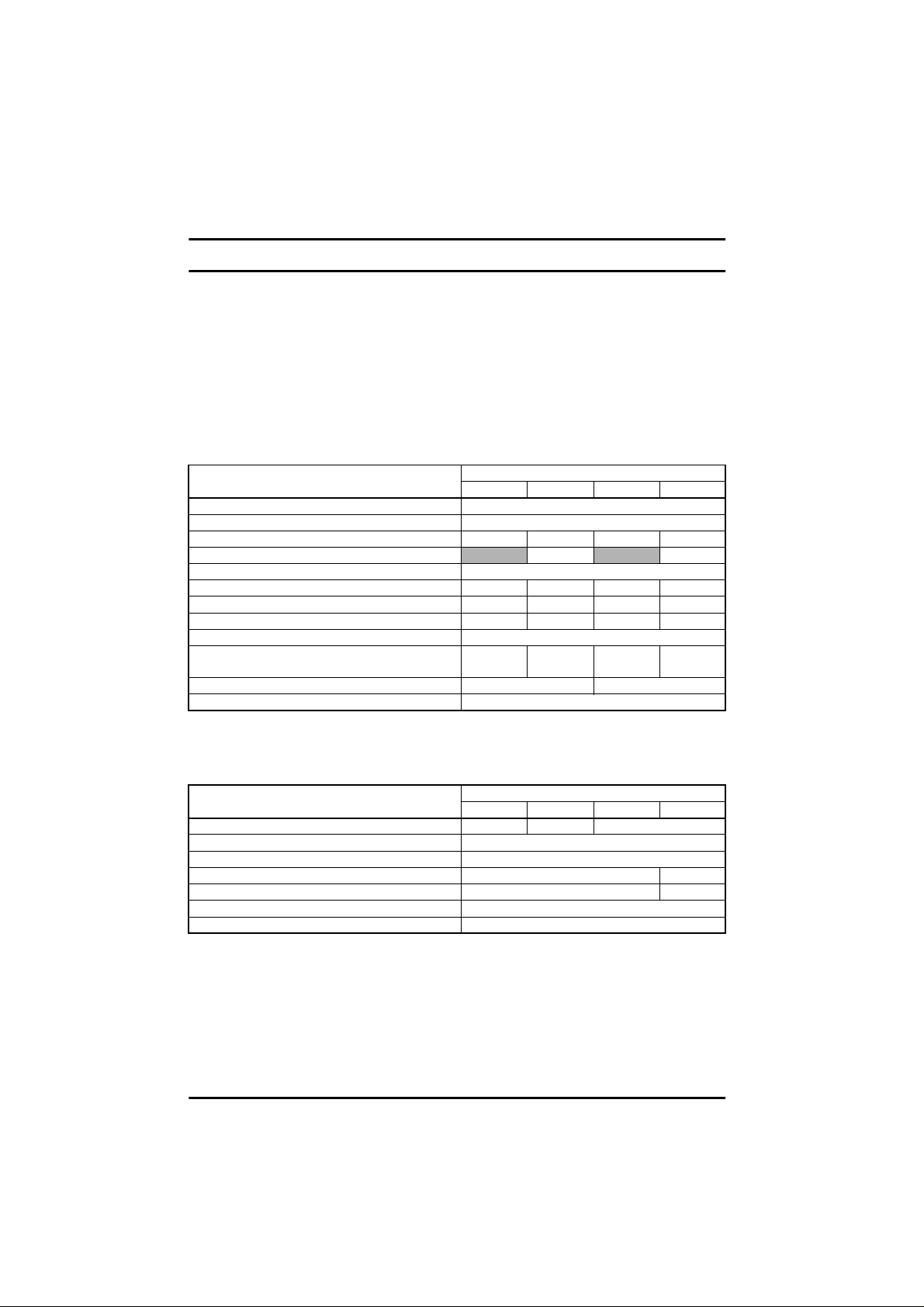
Table 3.1 Commander SE Size 1
MODEL SE11200...
025 037 055 075
AC supply voltage and frequency Single phase 200 - 240V +/- 10% 48 - 62Hz
Input displacement factor (cosφ) >0.97
Nominal motor power - kW 0.25 0.37 0.55 0.75
Nominal motor power - HP
Output voltage and frequency 3phase, 0 to input voltage, 0 to 1000Hz
100% RMS output current - A 1.5 2.3 3.1 4.3
150% overload current for 60 secs - A 2.3 3.5 4.7 6.5
Typical full load input current - A* 5.6 6.5 8.8 11.4
Typical inrush current - A** (dur ation <10ms) 100
Drive power losses at 230VAC at 6kHz switching
frequency - W 18 24 37 56
Weight - k g/lb 1.1/2.4 1.25/2.75
Cooling fan fitted No
* See section 3.1.1.
** For an explanation of inrush current, see section 3.1.2.
0.50 1.0
Table 3.2 Recommended supply fuses and cables
MODEL SE11200...
025 037 055 075
Recommended input supply fuse - A 6 10 16
Control cable mm²
AWG 20
Recommended input cable mm² 1.0 1.5
AWG 16 14
Recommended motor cable mm² 1.0
AWG 16
≥
0.5
Commander SE User Guide
6 Issue Number 5
Page 11
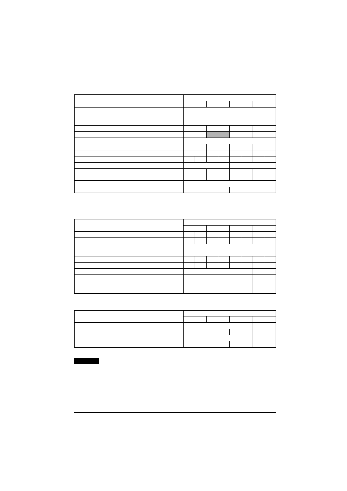
Table 3.3 Commander SE Size 2, 200V dual rated units
MODEL SE2D200...
075 110 150 220
AC supply voltage and frequency Single or 3 phase 200 to 240V +/- 10% , 48
Input displacement factor (cosφ) >0.97
Nominal motor power - kW 0.75 1.1 1.5 2.2
Nominal motor power - HP 1.0
Output voltage and frequency 3 phase, 0 to input voltage, 0 to 1000Hz
100% RMS output current - A 4.3 5.8 7.5 10.0
150% overload current for 60 secs - A 6.5 8.7 11.3 15.9
Typical full load input current - A* 1ph/3ph 11.0 5.5 15.1 7.9 19.3 9.6 26.2 13.1
Typical inrush current - A**(duration <10ms) 55 35
Drive power losses at 230VAC at 6kHz switching
frequency - W 54 69 88 125
Weight - kg/lb 2.75 / 6
Cooling fan fitted No Yes
to 62Hz
2.0 3.0
* See section 3.1.1.
** For an explanationof inrush current, see section 3.1.2.
Table 3.4 Recommended supply fuses and cables
MODEL SE2D200...
075 110 150 220
1ph 3ph 1ph 3ph 1ph 3ph 1ph 3ph
Recommended input supply fuse - A 16 10 20 16 25 16 32 20
Control cable mm²
AWG 20
Recommended input cable mm² 1.5 1.0 2.5 1.5 2.5 1.5 4.0 2.5
AWG 1416121412141012
Recommended motor cable mm² 1.0 1.5
AWG 16 14
Recommended braking resistor cable mm² 1.0 1.5
AWG 16 14
≥
0.5
Table 3.5 Braking resistors
MODEL SE2D200...
075 110 150 220
Minimum braking resistor value Recommended braking resistor value Maximum braking current - A 9 11
Resistor peak power rating - kW 1.8 2.4 3.5
NOTE
Before fitting a braking resistor please read the information on
Ω
Ω
50 40
100 75 50
Braking, and the Warnings on High Temperatures and Overload
Protection at the end of this section.
Commander SE User Guide
Issue Number 5 7
Page 12
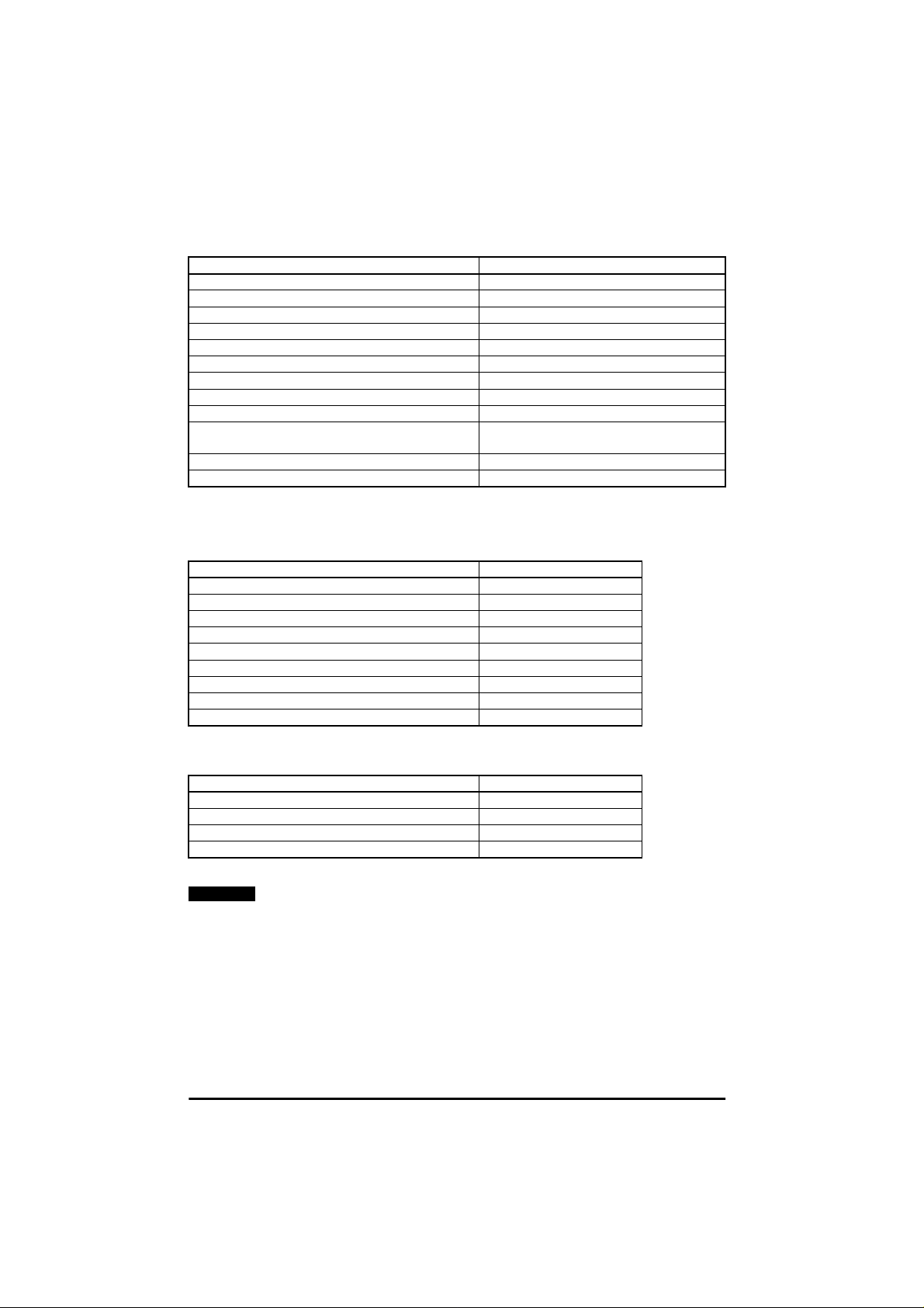
Table 3.6 Commander SE Size 2, 200V Three phase units
MODEL SE23200400
AC supply voltage and frequency 3 phase 200 to 240V +/- 10%, 48 to 62Hz
Input displacement factor (cosφ) >0.97
Nominal motor power - kW 4
Nominal motor power - HP 5
Output voltage and frequency 3 phase, 0 to input voltage, 0 to 1000Hz
100% RMS output current - A 17.0
150% overload current for 60 secs - A 25.5
Typical full load input curr ent - A* 21
Typical inrush current - A** (dur ation <10ms) 35
Drive power losses at 230VAC at 6kHz switching
frequency - W 174
Weight - kg/lb 2.75 / 6
Cooling fan fitted Yes
* See section 3.1.1.
** For an explanation of inrush current, see section 3.1.2.
Table 3.7 Recommended supply fuses and cables
MODEL SE23200400
Recommended input supply fuse - A 32
Control cable mm²
AWG 20
Recommended input cable mm² 4.0
AWG 10
Recommended motor cable mm² 2.5
AWG 12
Recommended braking resistor cable mm² 2.5
AWG 12
≥
0.5
Table 3.8 Braking resistors
MODEL SE23200400
Minimum braking resistor value Recommended braking resistor value Maximum braking current - A 14
Resistor peak power rating - kW 5.9
NOTE
Before fitting a braking resistor please read the information on
Ω
Ω
30
30
Braking, and the Warnings on High Temperatures and Overload
Protection at the end of this section.
Commander SE User Guide
8 Issue Number 5
Page 13
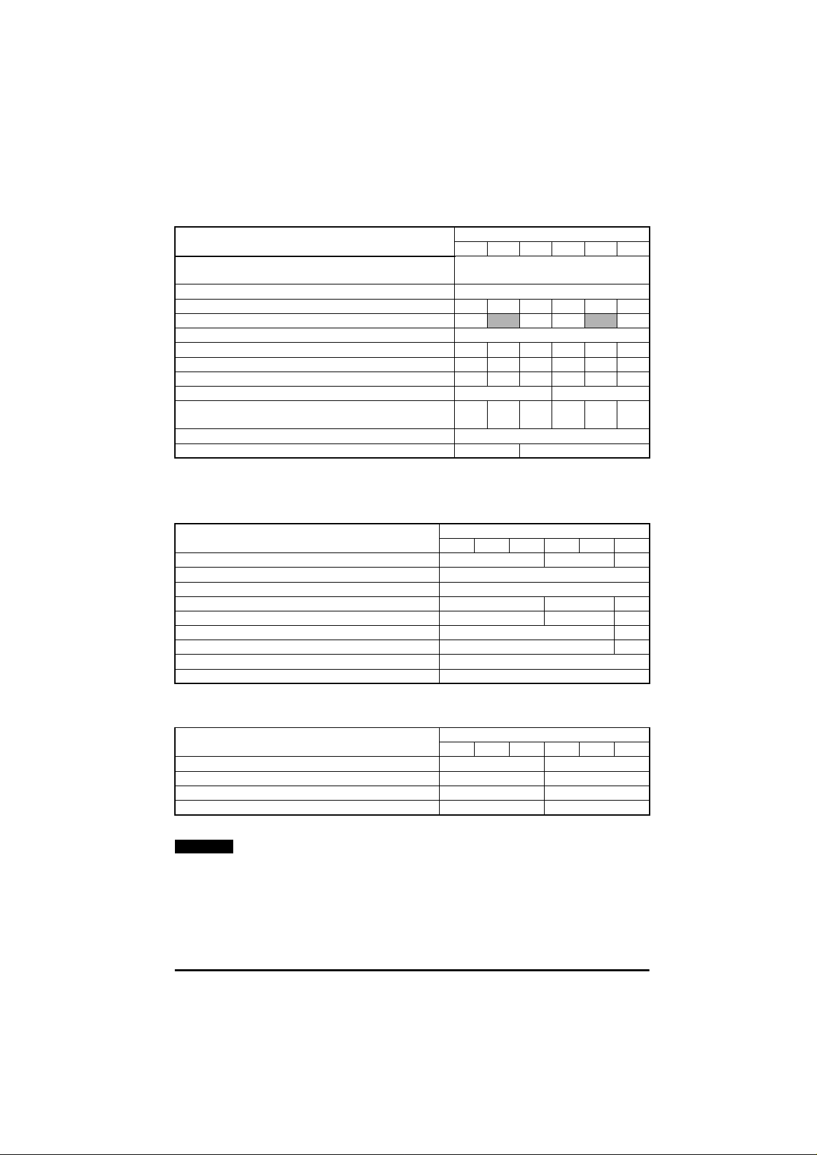
Table 3.9 Commander SE Size 2, 400V Three phase units
MODEL SE23400...
075 110 150 220 300 400
AC supply voltage and frequency 3 phase 380 to 4 80V +/- 10%, 48 to
Input displacement factor (cosφ) >0.97
Nominal motor power - kW 0.75 1.1 1.5 2.2 3.0 4.0
Nominal motor power - HP 1.0
Output voltage and frequency 3 phase, 0 to input voltage, 0 to 1000Hz
100% RMS output current - A 2.1 3.0 4.2 5.8 7.6 9.5
150% overload current for 60 secs - A 3.2 4.5 6.3 8.7 11.4 14.3
Typical full load input current - A*400V, 50Hz/480V, 60Hz 3.6 4.8 6.4 9.3 11 14
Typical inrush current - A** (duration <10ms) 90 60
Drive power losses at 480VAC at 6kHz switching
frequency - W 43 57 77 97 122 158
Weight - kg/lb 2.75 / 6
Cooling fan fitted No Yes
62Hz
2.0 3.0 5.0
* See section 3.1.1.
** For an explanationof inrush current, see section 3.1.2.
Table 3.10 Recommended fuses and cables
MODEL SE23400...
075 110 150 220 300 400
Recommended input supply fuse - A 10 16 20
Control cable mm²
AWG 20
Recommended input cable mm² 1.0 1.5 2.5
AWG 16 14 12
Recommended motor cable mm² 1.0 1.5
AWG 16 14
Recommended braking resistor cable mm² 1.5
AWG 14
≥
0.5
Table 3.11 Braking Resistors
MODEL SE23400...
075 110 150 220 300 400
Minimum braking resistor value Recommended braking resistor value Maximum braking current - A 10 12.5
Resistor peak power rating - kW 3.4 6.9
NOTE
Before fitting a braking resistor please read the information on
Ω
Ω
100 75
200 100
Braking, and the Warnings on High Temperatures and Overload
Protection at the end of this section.
Commander SE User Guide
Issue Number 5 9
Page 14

Table 3.12 Commander SE Size 3, 200V units
MODEL SE33200...
550 750
AC supply voltage and frequency 3 phase 200 to 240V +/-10%, 48 to 62Hz
Input displacement factor (cosφ) >0.97
Nominal motor power - kW 5.5 7.5
Nominal motor power - HP 7.5 10.0
Output voltage and frequency 3 phase, 0 to input voltage, 0 to 1000H z
100% RMS output current - A 25.0 28.5
150% overload current for 60 secs - A 37.5 42.8
Typical full load input curr ent - A* 22.8 24.6
Typical inrush current - A** (dur ation <10ms) 44
Drive power losses at 230VAC at 6kHz switching
frequency - W
Weight - kg/lb 6 / 13.2
Cooling fan fitted Yes
230 305
* See section 3.1.1.
** For an explanation of inrush current, see section 3.1.2.
Table 3.13 Recommended fuses and cables
MODEL S E33200...
550 750
Recommended input supply fuse - A 30
Control cable mm² >
AWG 20
Recommended input cable mm² 4.0
AWG 10
Recommended motor cable mm² 4.0
AWG 10
Recommended braking resistor cable mm² 4.0
AWG 10
0.5
Table 3.14 Braking Resistors
MODEL S E33200...
550 750
Minimum braking resistor value Recommended braking resistor value Maximum braking current - A 28.0
Resistor peak power rating - kW 11.8
NOTE
Before fitting a braking resistor please read the information on
Ω
Ω
11.0
15.0
Braking, and the Warnings on High Temperatures and Overload
Protection at the end of this section.
Commander SE User Guide
10 Issue Number 5
Page 15
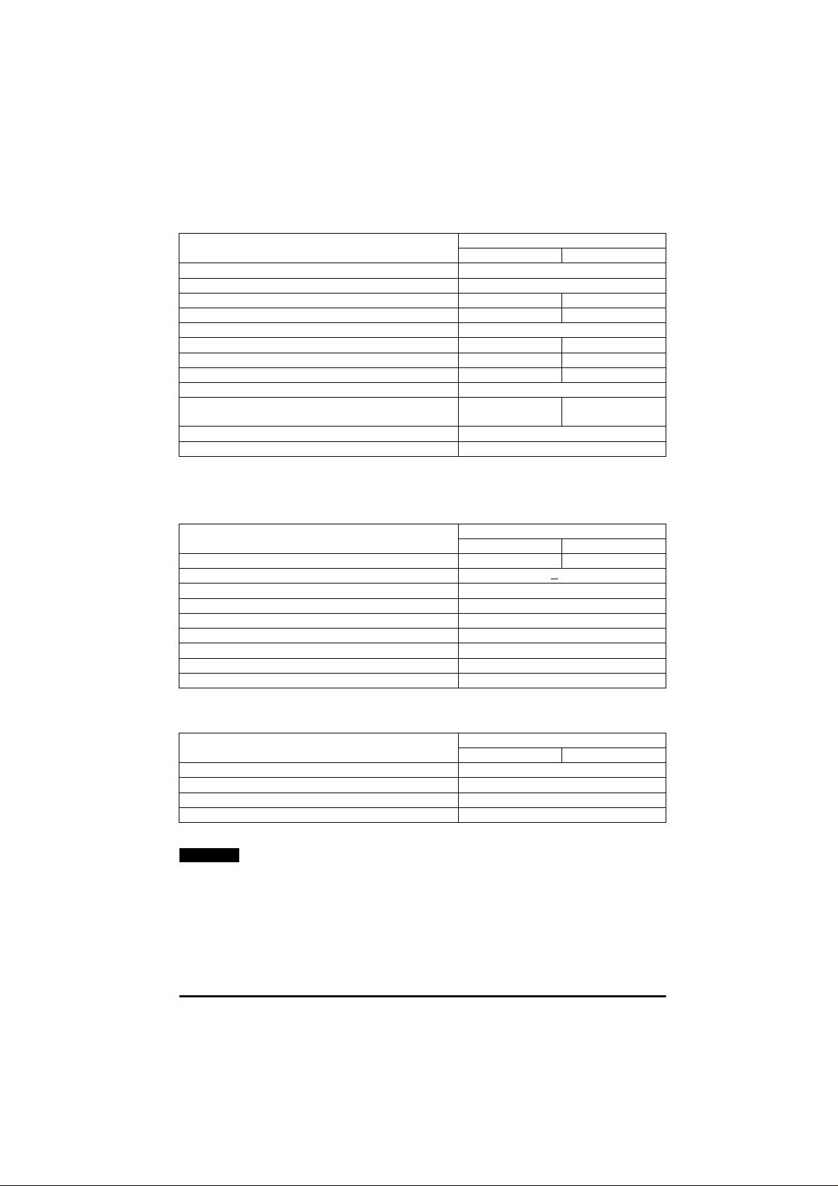
Table 3.15 Commander SE Size 3, 400V units
MODEL SE33400...
550 750
AC supply voltage and frequency 3 phase 380 to 480V +/-10%, 48 to 62Hz
Input displacement factor (cosφ) >0.97
Nominal motor power - kW 5.5 7.5
Nominal motor power - HP 7.5 10.0
Output voltage and frequency 3 phase, 0 to input voltage, 0 to 1000Hz
100% RMS output current - A 13.0 16.5
150% overload current for 60 secs - A 19.5 24.8
Typical full load input current - A* 13.0 15.4
Typical inrush current - A** (duration <10ms) 80
Drive power losses at 230VAC at 6kHz switching
frequency - W
Weight - kg/lb 6 / 13.2
Cooling fan fitted Yes
190 270
* See section 3.1.1.
** For an explanationof inrush current, see section 3.1.2.
Table 3.16 Recommended fuses and cables
MODEL SE33400...
550 750
Recommended input supply fuse - A 16 20
Control cable mm² >
AWG 20
Recommended input cable mm² 2.5
AWG 12
Recommended motor cable mm² 2.5
AWG 12
Recommended braking resistor cable mm² 2.5
AWG 12
0.5
Table 3.17 Braking Resistors
MODEL SE33400...
550 750
Minimum braking resistor value Recommended braking resistor value Maximum braking current - A 16.6
Resistor peak power rating - kW 13.8
NOTE
Before fitting a braking resistor please read the information on
Ω
Ω
33.0
50
Braking, and the Warnings on High Temperatures and Overload
Protection at the end of this section.
Commander SE User Guide
Issue Number 5 11
Page 16
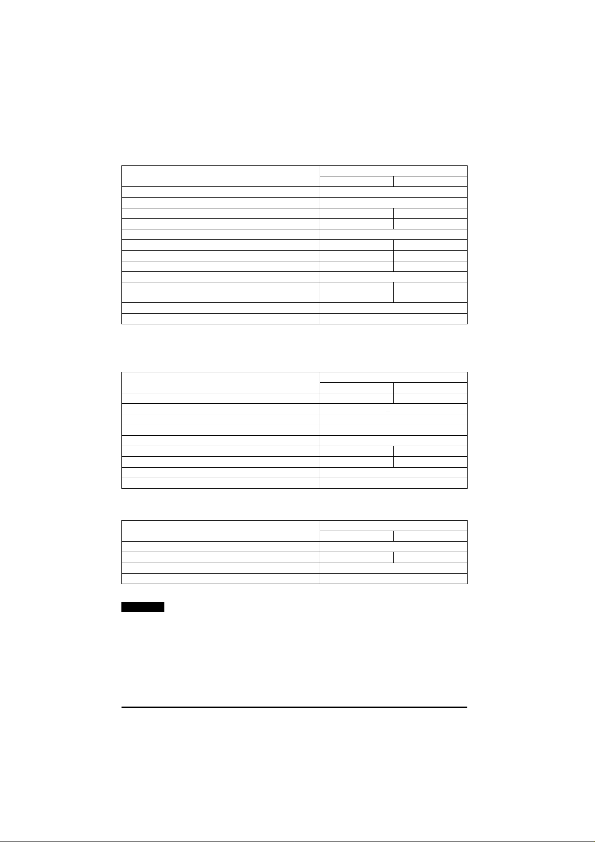
Table 3.18 Commander SE Size 4, 400V units
MODEL SE4340...
1100 1500
AC supply voltage and frequency 3 phase 380 to 480V +/-10%, 48 to 62Hz
Input displacement factor (cosφ) >0.97
Nominal motor power - kW 11 15
Nominal motor power - HP 15 20
Output voltage and frequency 3 phase, 0 to input voltage, 0 to 1000H z
100% RMS output current - A 24.5 30.5
150% overload current for 60 secs - A 36.75 45.75
Typical full load input curr ent - A* 23 27.4
Typical inrush current - A** (dur ation <10ms) 40
Drive power losses at 230VAC at 6kHz switching
frequency - W
Weight - k g/lb 11/ 24.2
Cooling fan fitted Yes
400 495
* See section 3.1.1.
** For an explanation of inrush current, see section 3.1.2.
Table 3.19 Recommended fuses and cables
MODEL SE4340...
1100 1500
Recommended input supply fuse - A 32 40
Control cable mm² >
AWG 20
Recommended input cable mm² 4.0
AWG 10
Recommended motor cable mm² 4.0 6.0
AWG 10 8
Recommended braking resistor cable mm² 6.0
AWG 8
0.5
Table 3.20 Braking Resistors
MODEL SE4340...
1100 1500
Minimum braking resistor value Recommended braking resistor value Maximum braking current - A 30
Resistor peak power rating - kW 25.5
NOTE
Before fitting a braking resistor please read the information on
Ω
Ω
40 30
27
Braking, and the Warnings on High Temperatures and Overload
Protection at the end of this section.
Commander SE User Guide
12 Issue Number 5
Page 17
Braking Resistors - High Temperatures
Braking resistors can reach high temperatures. Locate braking
resistors so that damage cannot result. Use cable having
WARNING
insulation capable of withstanding high temperatures.
Braking Resistors - Overload Protection
It is essential that an overload protection device is
incorporated in the braking resistor circuit. This is described
WARNING
in section 5.1.1
Braking Resistor
Thermal Protection Circuit for an Optional
.
3.1.1 *Input current
The input current values given could be exceeded where the supply fault
current is greater than 5kA or the phase voltages are not balanced. In
these cases, input line reactors are recommended. See section 4.4.3.
3.1.2 **Temperature effects on inrush currents
Due to the design of the inrush circuit, the inrush current will be lower on
the first power up of the Drive after a period of non-use and when the
Drive is cold. The inrush current will increase when the time between
power ups is short and the internal ambient temperature within the Drive
is high.
3.2 General data
IP Rating.
Size 1:
Sizes 2, 3 & 4:
If the Drive is not mounted in this way, hazardous live parts will be
exposed and the IP Rating of the Drive will b e invalid.
WARNING
Input phase
imbalance:
Ambient temperature: -10°Cto+40°C(14°F to 104°F) at 6kHz switching
IP20
The Ingress Protection rating is applicable to the Dr ive
when the supplied rubber grommets are fitted into the
gland plate.
IP20
The Ingress Protection rating is applicable to the Dr ive
when the supplied rubber grommets are fitted into the
gland plate and the Drive is mounted on a s olid flat
surface.
Phase imbalance not to exceed 2% negative phase
sequence
frequency
-10°Cto+50°C(14°F to 122°F) at 3kHz switching
frequency with derating. See
Advanced User Guide
Commander SE
for Derating Curves.
Commander SE User Guide
Issue Number 5 13
Page 18

Storage temperature: -40°Cto+60°C (-40°F to 140°F) for 12 months
Altitude: Reduce the normal full-load current by 1% for every
Humidity: Maximum relative humidity 95% (non-condensing)
Materials: Flammability rating of main enclosur e: UL94- 5VA
Vibration (random):
Vibration (sinusoidal)
Bump: Packaged - tested to 40g, 6ms, 100 times/direction for
Frequency accuracy: 0.01%
Resolution: 0.1Hz
Output frequency
range:
Startsper hour: Byusing the electronic control terminals: Unlimited
Power up delay: 1 second maximum (Allow at least 1 second before
Serial
Communications:
Switching
Frequencies:
EMC: EN50082-2 and EN61800-3 for immunity
maximum.
100m (325ft) above 1000m (3250ft) to a m aximum of
4000m (13000ft).
Grommets: UL94-V1
Unpackaged - tested to 0.01g²/Hz (equivalent to 1.2g
rms) from 5 to 150Hz for 1 hour in each of 3 axes in
accordance with IEC68-2-34 and IEC68-2-36.
Unpackaged - tested from 2-9Hz, 3.5mm displacement;
9-200Hz 10m/s
acceleration. Duration - 15 minutes in each of 3 axes.
Sweep rate 1 octave/minute.
Test in accordance with IEC68-2-6.
all 6 directions as in IEC68-2-29
Unpackaged - tested to 25g, 6ms, 100 times/direction
for all 6 directions in accordance with IEC68-2-29
0 to 1000Hz
By sw itching of the supply: 20 starts per hour maximum
(3 minute intervals between starts)
monitoring the state of the status relay contacts,
communicating with the Drive via serial
communications etc.)
ANSI 2-wire EIA485 protocol via RJ45 connector
3, 6, and 12 kHz are available with Intelligent Thermal
Management software automatically changing the
switching frequencies depending on load conditions,
heatsink temperature and output frequency, to prevent
heatsink overtemperature trips.
EN61800-3 second environment, without RFI filter
EN50081-1*, EN50081-2 and EN61800-3 firs t
environment, with optional RFI filter. See sections 3.3
and 4.5.
* Size 1 units only.
2
acceleration; 200-500Hz, 15m/s
2
Commander SE User Guide
14 Issue Number 5
Page 19
3.3 RFI Filters
RFI filters are available as optional extra parts where required.
NOTE
Forcompliance with EN61800-3 in the second environment, no filter
is required.
Table 3.21 Commander SE Size 1
Used with Filter Part
SE11200025 to
SE11200075
No
4200-6101 Y Y 20
4200-6102 Y Y Y 75
4200-6103 Y Y Y 15
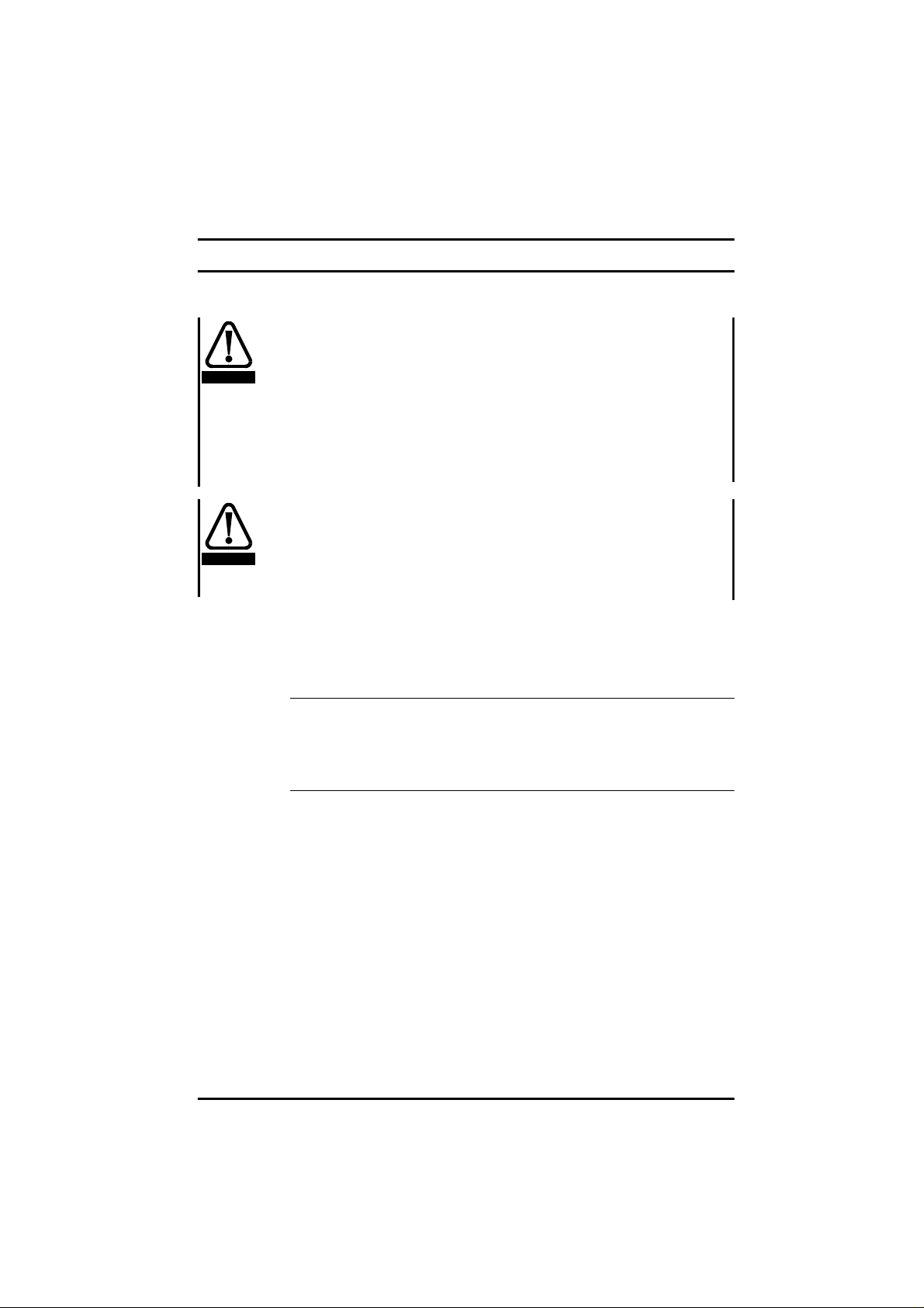
Table 3.22 Commander SE Size 2 - 200V, 26A, 1 phase
Used with Filter Part
SE2D200075 to
SE2D200220
No
4200-6201 Y Y Y 100
4200-6204 Y Y 50
4200-6205 Y Y Y 15
Table 3.23 Commander SE Size 2 - 200 / 400V, 16A, 3 phase
Used with Filter Part
SE2D200075 to
SE2D200220
No
4200-6202 Y Y Y 100
4200-6304 Y Y 15
4200-6207 Y Y Y 45
Standard Low leakage Low cost Footprint Side
Filter Type Mounting Max motor
Filter Type Mounting Max motor
Standard Low leakage Low cost Footprint Side
Filter Type Mounting Max motor
Standard Low leakage Low cost Footprint Side
cablelength
(m)
cablelength
(m)
cablelength
(m)
Table 3.24 Commander SE Size 2 - 200 / 400V, 16A, 3 phase
Used with Filter Part
SE23400075 to
SE23400400
No
4200-6202 Y Y Y 100
4200-6304 Y Y 15
4200-6207 Y Y Y 20
Standard Low leakage Low cost Footprint Side
Filter Type Mounting Max motor
cablelength
(m)
Table 3.25 Commander SE Size 2 - 200V, 26A, 3 phase
Used with Filter Part
SE23200400 4200-6203 Y Y Y 100
No
4200-6303 Y Y 15
4200-6209 Y Y Y 45
Standard Low leakage Low cost Footprint Side
Filter Type Mounting Max motor
cablelength
(m)
Commander SE User Guide
Issue Number 5 15
Page 20
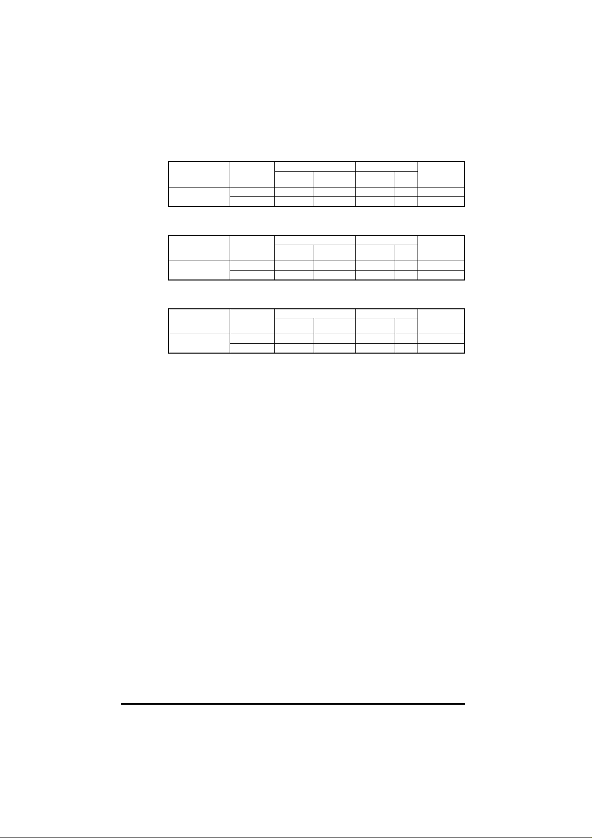
Table 3.26 Commander SE Size 3 - 200V, 30A
Used with Filter Part
SE33200550 to
SE33200750
No
4200-6302 Y Y Y 100
4200-6303 Y Y 15
Filter Type Mounting Max motor
Standard Lowcost Footprint Side
Table 3.27 Commander SE Size 3 - 400V, 18A
Used with Filter Part
SE33400550 to
SE33400750
No
4200-6301 Y Y Y 100
4200-6304 Y Y 15
Filter Type Mounting Max motor
Standard Lowcost Footprint Side
Table 3.28 Commander SE Size 4
Used with Filter Part
SE43401100 to
SE43401500
No
4200-6401 Y Y Y 100
4200-6402 Y Y 15
Filter Type Mounting Max motor
Standard Lowcost Footprint Side
cable length
(m)
cable length
(m)
cable length
(m)
For complete EMC information, refer to Section 4.5
compatibility (EMC).
Electromagnetic
Commander SE User Guide
16 Issue Number 5
Page 21
4 Installing the Drive
4.1 Safety information
Follow the instructions
The mechanical and electrical installation instructions must
be adhered to. Any questions or doubt should be referred to
WARNING
WARNING
4.2 Planning the installation
the supplier of the equipment. It is the responsibility of the
owner or user to ensure that the installation of the Drive and
any external option unit, and the way in which they are
operated and maintained,comply with the requirementsof the
Health and Safety at Work Act in the United Kingdom or
applicablelegislation and regulations and codesof practice in
the country in which the equipment is used.
Competence of the installer
The Drive must be installed by professional assemblers who
are familiar with the requirements for safety and EMC. The
assembler is responsiblefor ensuring that the end product or
system complies with all the relevant laws in the country
whereitistobeused.
The following considerations must be made when planning the
installation:
Access
Access must be restricted to authorised personnel only.
Safety regulations which apply at the place of use must be
complied with.
Environmental protection
The Drive must be protected from:
• moisture, including dripping water or spraying water
and condensation. An anti-condensation heater may
be required, which must be switched off when the
Drive is running.
• contamination with electrically conductive material
• temperature beyond the specified operating and
storage ranges
Commander SE User Guide
Issue Number 5 17
Page 22

Cooling
The heat produced by the Drive must be removed without
its specified operating temperature being exceeded. Note
that a sealed enclosure gives much reduced cooling
comparedwitha ventilatedone,and may needto belarger
and/or use internal air circulating fans. For further
information on enclosure design, please refer to the
Commander SE Advanced User Guide.
Electrical safety
The installation must be safe under normal and fault
conditions. Electrical installation instructions are given
later in this chapter.
Fire protection
TheDrive enclosureis not classified as a fire enclosure. A
separate fire enclosure must be provided.
Electromagnetic compatibility
Variable speed Drives are powerful electronic circuits
which can cause electromagnetic interference if not
installed correctly with careful attention to the layout of the
wiring.
Some simple routine precautions can prevent disturbance
to typical industrial control equipment.
If it is necessary to meet strict emission limits, or if it is
known that electromagnetically sensitive equipment is
located nearby, then full precautions must be observed.
These will include the use of RFI filters at the Drive inputs,
which must be located very close to the Drives. Space
mustbe made available for the filters and allowance made
for carefully segregated wiring. Both levels of precautions
are given further on in this chapter.
Hazardous areas
The Drive must not be located in a classified hazardous
areas unless it is installed in an approved enclosure and
the installation is certified.
Commander SE User Guide
18 Issue Number 5
Page 23
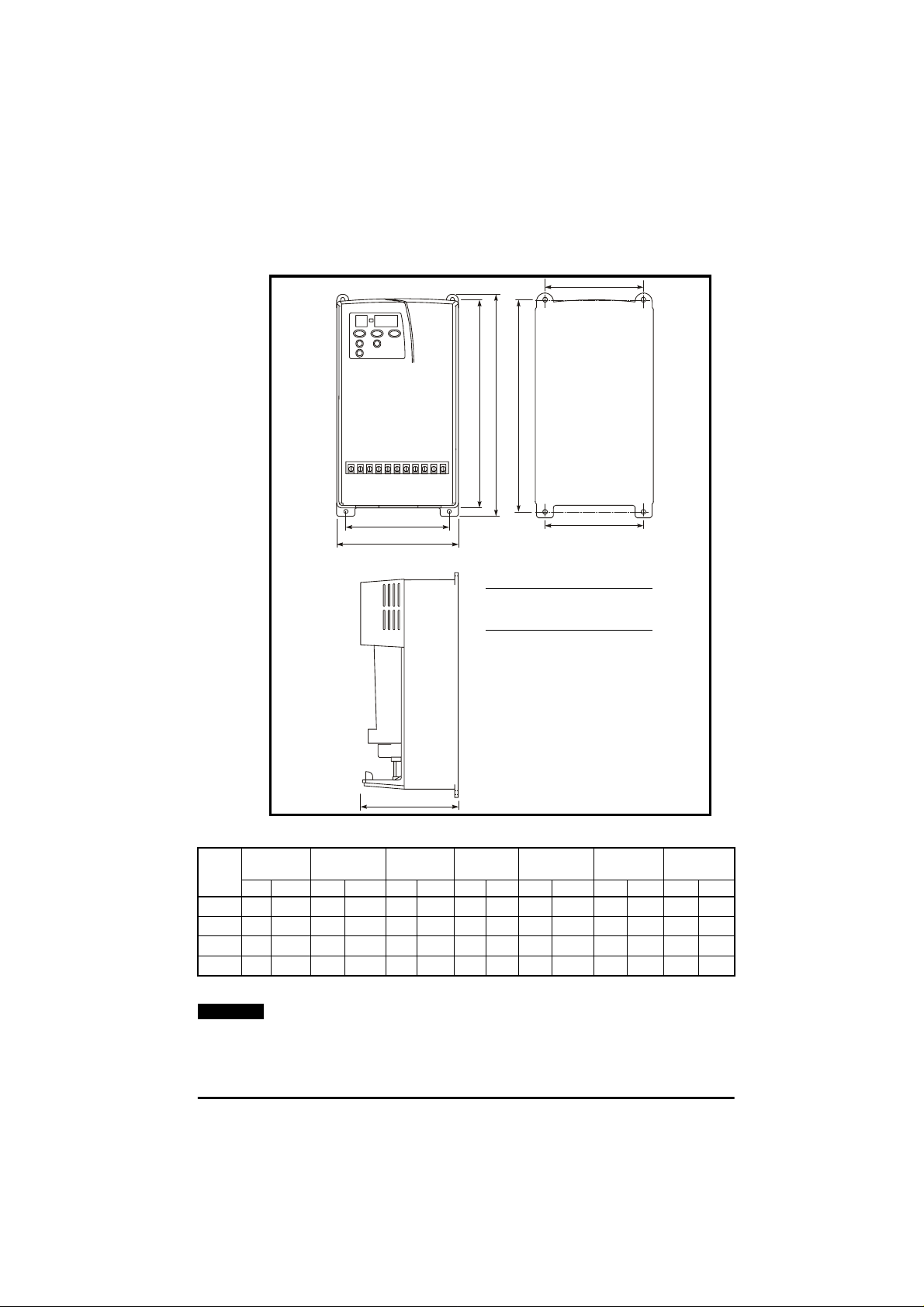
4.3 Mechanical installation
G
4.3.1 Drive and Mounting Dimensions
F
C
B
EFA
Commander SE Size 1 & 2
4 x M4 holes in heatsink
Commander SE Size 3 & 4
4 x M5 holes in heatsink
D
Figure 4.1 Drive and mounting dimensions
Drive
Size
1191
2280
3336
4412
NOTE
ABCDEFG
mm in mm in mm in mm in mm in mm in mm in
33
7
/
64
1
/
11
64
7
/
13
32
7
16
/
32
175
259
315
389
57
6
/
64
3
/
10
16
13
/
12
32
5
15
/
16
102
147
190
250
1
4
/
64
25
/
5
32
31
/
7
64
27
9
/
32
130
130
155
185
7
5
/
64
7
/
5
64
7
/
6
64
9
7
/
32
181.5
265
320
397
9
7
/
64
7
/
10
16
19
/
12
32
5
15
/
8
84
121.5
172
228
5
84
3
/
16
25
/
4
32
25
/
6
32
63
8
/
64
121.5
164
217
3
25
4
29
6
35
8
The Drive should be mounted vertically. A mounting template is
5
/
16
/
32
/
64
/
64
provided on the Drive packing carton to aid installation.
Commander SE User Guide
Issue Number 5 19
Page 24
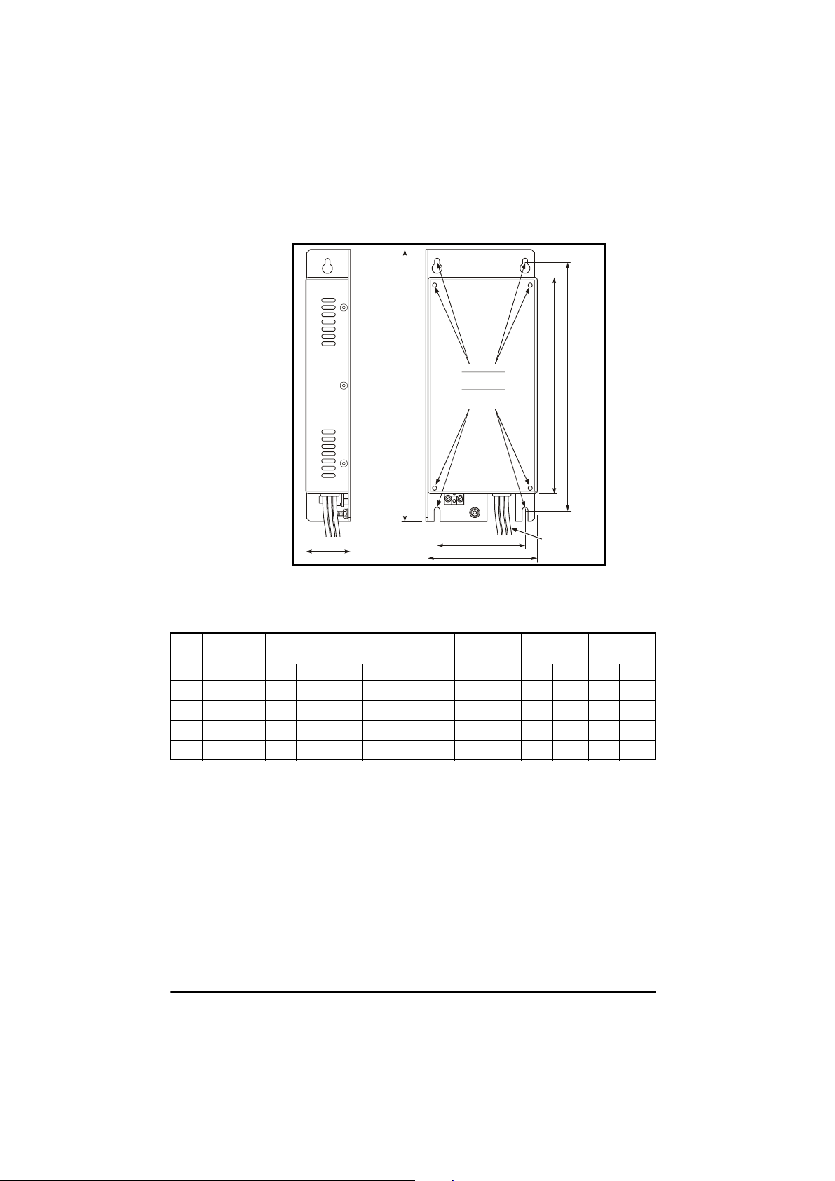
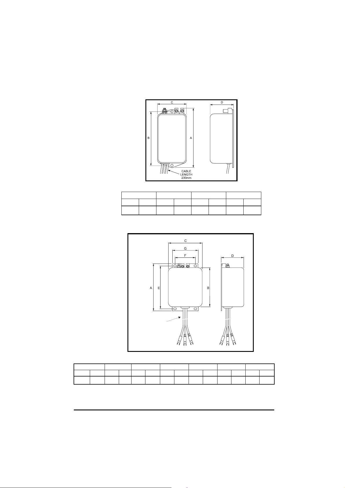
4.3.2 Commander SE standard and low earth leakage Footprint/ Side
mounting RFI Filter:
Size 1 and 2
8 x M4 holes
Size 3 and 4
8 x M5 holes
for footprint mounting
ÿ
Cable length
Figure 4.2 RFI filter dimensions
Drive
Size
1
2
3
4
ABCDE FCable
mm in mm in mm in mm in mm in mm in mm in
17
242
/
9
32
330 13 281
5
385
/
15
32
25
467
/
18
64
195
336
414
43
/
7
64
1
/
11
16
15
/
13
64
19
/
16
64
100
148
190
246
15
/
3
16
13
/
5
16
31
/
7
64
11
/
9
16
37
40
/
1
64
49
45
/
1
64
31
50
/
1
32
11
55
/
2
64
225
313
368
448
7
80
/
8
8
21
/
12
64
31
/
14
64
41
/
17
64
122
164
215
3
4
6
8
Length
5
/
32
51
/
64
29
/
64
15
/
32
190
250
270
320
31
/
7
64
27
/
9
32
5
/
10
8
19
/
12
32
Commander SE User Guide
20 Issue Number 5
Page 25
4.3.3 Commander SE Size 1 Low Cost RFI Filter mounting dimensions,
4200-6101.
Figure 4.3 Size 1 Low cost filter dimensions
ABCD
mm in mm in mm in mm in
113.5
15
103
/
4
32
1
4
/
16
58
9
2
45.5
/
32
51
1
/
64
4.3.4 Commander SE Size 2 and 3 Low cost single and three phase RFI
Filter mounting dimensions, 4200-6204 and 4200-6304.
Cable length
4200-6204 = 250mm
4200-6304 = 300mm
Figure 4.4 RFI filter dimensions
ABCDEFG
mm in mm in mm in mm in mm in mm in mm in
119
11
4
/
16
98.5
7
3
/
8
85.5
21
3
/
64
57.6
17
2
/
64
109
19
4
51266
/
64
19
2
/
32
Commander SE User Guide
Issue Number 5 21
Page 26

4.3.5 Commander SE Size 2, 3 and 4 Low cost three phase RFI Filter
h
mounting dimensions, 4200-6303 & 4200-6402.
C
F
B
H
E
A
G
Figure 4.5 RFI Filter Dimensions
ABCDEF G H
mm in mm in mm in m m in mm in mm in mm in mm in
4200-6303 133
4200-6402 143
15
5
/
64
5
5
/
8
120
130
23
4
/
32
7
5
/
64
118
128
41
4
/
64
1
5
/
32
4.3.6 Minimum Mounting Clearances
10mm
3
(/in)
8
70
80
100mm
3
(/in)
D
Cable lengt
300mm
3
2
/
4
5
3
/
32
1
8
4
80
80
20mm
3
(/in)
4
3
3
5
/
5
/
32
32
100mm
3
(/in)
103
113
4
1
4
/
16
29
4
/
34
10mm
3
(/in)
8
1
8
90
100
35
3
/
64
15
3
/
16
130.6
143
9
5
/
64
5
5
/
8
Figure 4.6 Minimum mounting clearances (applies to all Drive
sizes).
Commander SE User Guide
22 Issue Number 5
Page 27

4.4 Electrical installation
Electric shock risk
The voltages present in the following locations can cause
severe electric shock and may be lethal:
WARNING
• AC supply cables and connections
• Output cables and connections
• Many internal parts of the Drive, and external option units
Isolation device
The AC supply must be disconnected from the Drive using a n
approved isolation device before any cover is removed from
WARNING
the Drive or before any servicing work is performed.
STOP function
The STOP function does not remove dangerous voltages from
the Drive or any external option units.
WARNING
Stored charge
The Drive contains capacitors that remain charged to a
potentially lethal voltage after the AC supply has been
WARNING
disconnected. If the Drive has been energised, the AC supply
must be isolated at least ten minutes before work may
continue.
Normally, the capacitors are discharged by an internal
resistor. Undercertain, unusual fault conditions, it is possible
that the capacitors may fail to discharge,or be prevented from
being discharged by a voltage applied to the outputterminals.
If the Drive has failed in a manner that causes the display to go
blank immediately, it is possible the capacitors will not be
discharged. In this case, consult Control Techniques or their
authorised distributor.
AC supply by plug and socket
Special attention must be given if the Drive is installed in
equipment which is connected to the AC s upply by a plug and
WARNING
socket. The AC supply terminals of the Drive are connected to
the internal capacitors through rectifier diodes which are not
intended to give safety isolation. If the plug terminals can be
touched when the plug is disconnected from the socket, a
means of a utomatically isolating the plug from the Drive must
be used (eg. a latching relay).
Commander SE User Guide
Issue Number 5 23
Page 28

4.4.1 AC supply requirements
The following types of AC supply are suitable.
Single phase models:
• Single phase (i.e. between one phase and neutral of a starconnected three phase supply)
• Between two phases of a three phase supply (any one phase can be
grounded)
Three phase models:
• Three phase star or delta supply of the correct voltage (any one
phase or neutral can be grounded)
Dual rated 200V models:
• Any of the above
NOTE
The input current differs for single phase and three phase supplies.
Supply voltage and current information is given in Chapter 3
Data
.
4.4.2 Cables and fuses
Recommendedcable sizes are given in Chapter 3
are only a guide. Refer to local wiring regulationsfor the correct size of
cables. In some cases a larger cable is required to avoid excessive
voltage drop.
Use 105°C(221°F) (UL 60/75°C temp rise) pvc-insulated cable with
copper conductors having a suitable voltage rating, for the following
power connections:
• AC supply to RFI filter (when used)
• AC supply (or RFI filter) to Drive
• Drive to motor
• Drive to braking resistor
Fuses
The AC supply to the Drive must be fitted with suitable protection against overload and short-circuits. The tables in Chapter
3
Technical Data
WARNING
observe this requirement will cause risk of fire.
Technical
Technical Data
.They
show recommended fuse ratings. Failure to
A fuse or other protection must be includedin all live connections to the
AC supply.
Commander SE User Guide
24 Issue Number 5
Page 29

WARNING
WARNING
An MCB (miniature circuit breaker) or MCCB (moulded case circuit
breaker) with type C tripping characteristics and the same rating as the
fuse(s), may be used in place of the fuse(s), on condition that the fault
current clearing capacity is sufficient for the installation.
Fuse Types
Europe: Type gG fuses complying with EN60269 parts 1 and 2.
USA: Bussman Limitron KTK series, class CC fast acting fuses.
Ground connections
The Drive must be connected to the system ground of the AC supply.
The ground wiring must conform to local regulations and codes of
practice.
The ground loop impedance m ust conform to the requirements
of local safety regulations. The ground connections must be
inspected and tested at appropriate intervals.
Earth and ground leakage
The Drive has a very small leakage current between the power lines and
ground, which is of no consequence.
The RFI filter has a higher leakage current, data is given in section 4.5.4,
Tables 4.11 to 4.14. When the standard and low cost filters are used, a
permanent fixed ground connection must be provided which does not
pass through a connector or flexible power cord.
Motor cables
For routine EMC precautions
Use either of the following:
• Cables containing three power conductors plus a ground conductor
• Three separatepower conductors plus a ground conductor
For full EMC precautions, where required (see section 4.5.2)
Use shielded (screened) or steel-wire armoured cable having three
power conductors plus a ground conductor.
If the cable between the Drive and the motor is to be inter-
rupted by a contactor or circuit breaker, ensure that the Drive is
disabled before the contactor or c ircuit breaker is opened or
closed. Severe arcing may occur if this circuit is interrupted
with the motor running at high current and low speed.
Maximum motor cable lengths
The capacitive loading of the Drive by the motor cable means that the
cable length limits shown in Table 4.1 must be observed. Failure to do so
can result in spurious OI.AC tripping of the Drive. If longer cable lengths
are required, consult your local Drive Centre or Distributor.
Commander SE User Guide
Issue Number 5 25
Page 30

Table 4.1 Maximum motor cable lengths
Drive Size Maximum motor cable length
1 75 246
2 100 330
3 100 330
4 100 330
High Capacitance Cables
Most cables have an insulatingjacket betweenthe cores and the armour
or shield; these cables have a low capacitance and are recommended.
Cables that do not have an insulating jacket tend to have high
capacitance.
If a high capacitance cable is used,the maximum cable lengths in Table
4.1 should be halved.
For further information please refer to the
User Guide
Multiple Motors
For advice on multiple motor applications where a number of small
motors are connected to the output of one Drive, please refer to the
Commander SE Advanced User Guide
4.4.3 Input Line reactors
When the Drive is connected to an AC supplywith a high fault current or
whichis subject tosevere disturbances,excessive peak currentmay flow
in the input power supply circuit of the Drive, which may cause nuisance
tripping, or in extreme cases, Drive failure.
An input AC line reactor should be installed in the following cases as it will
add the required impedance to reduce transient currents to a level which
can be tolerated by the input rectifier:
• supply capacity exceeds 200kVA
• fault current exceeds 5kA
• power factor correction equipment is connected close to the Drive
• large DC Drives with no or ineffective line reactors are connected to
the supply
• direct-on-line started motor(s) are connected to the same supply
and, when any of these motors are started, a dip is produced in
excess of 20% of the actual supply voltage
NOTE
EMC filters do not provide the same protection as input reactors.
Meters Feet
Commander SE Advanced
.
.
Commander SE User Guide
26 Issue Number 5
Page 31

4.4.4 AC Line reactor values
Table 4.2 AC Line reactor values
Drives used with Reactor
SE11200025, SE11200037 4402-0224 1 2.25 6.5 13 72 65 90
SE11200055, SE11200075,
SE2D200075, SE2D200110
SE2D200150, SE2D200220 4402-0226 1 0.5 26.2 52.4 82 90 105
SE23400075, SE23400110,
SE23400150
SE2D200075, SE2D200110,
SE2D200150, SE23400220,
SE23400300, SE23400400,
SE33400550, SE33400750
SE23200400, SE2D200220,
SE33200550, SE33200750
SE43401100, SE43401500 4402-0232 3 0.6 27.4 54.8 180 100 190
part
number
4402-0225 1 1.0 15.1 30.2 82 75 100
4402-0227 3 2.0 7.9 15.8 150 90 150
4402-0228 3 1.0 15.4 47.4 150 90 150
4402-0229 3 0.4 24.6 49.2 150 90 150
Input
phases
Induct-
ance
Contin-
uous
rms
current
mH A A L D H
Peak
current
Dimensions
(mm)
Line reactors also improve the input current waveform and reduce the
input current harmonic levels. Further information is included in the EMC
Data sheet which is available from Control Techniques’Drive Centres or
Distributors.
4.5 Electromagnetic compatibility (EMC)
This section gives installation guidelines for ensuring electromagnetic
compatibility. Further detailed information is provided in the EMC Data
sheets which are available from Control Techniques’Drive Centres or
distributors.
The Drive meets the standardsfor electromagnetic immunity stated in
section 3.2 without any special installation precautions. To prevent
possible nuisance tripping, it is recommended that all inductive circuits
associated with the Drive, for example relay coils, electromagnetic
brakes etc. should be fitted with appropriate suppression.
The following precautions should be taken to prevent the Drive from
causing interference with other electronic equipment:
For general use, and where the requirements of the Power Drive
Systemsstandard EN61800-3(IEC61800-3)for the secondenvironment
apply, the guidelines in section 4.5.1
Routine EMC precautions
shouldbe
followed.These are sufficient to prevent interference to generalpurpose
industrial and similar equipment of good quality recent design. A further
explanation of EN61800-3 and the second environment is given i n the
EMC Data sheets which are available from Control Techniques’ Drive
Centres or Distributors.
Commander SE User Guide
Issue Number 5 27
Page 32

Section 4.5.2
cases:
• When compliance with strict emissionstandards such as EN50081-1
or EN50081-2 is required.
• Where sensitive radio receiving or similar equipment is in use
nearby.
• Where sensitive electronic equipment with poor electromagnetic
immunity is in use nearby.
4.5.1 Routine EMC precautions
The routine precautions are based on the following principles:
1 The motor cable carries a highlevel of electrical ‘noise’. It should be
segregated from all signal circuits, and should include a ground
conductor linking the Drive ground directly to the motor frame.
2 The mains supply wiring also carries electrical noise and should be
segregated from signal circuits.
3 The Drive alsogenerates a noisefield so sensitivecircuits should not
be passed close to it.
4 “Noise” current flows in power wiringand returns through the ground
(earth). To minimise noiseloop areas, ground wires should be run as
close as possible to their associated power wires.
5 The Drive ground tends to be ‘noisy’, so it is preferable for the control
circuits to be groundedonly at the controller and not at the Drive.
4.5.2 Full EMC precautions
Figure 4.7 shows the requirements which be followed closely in order to
meet EMC emission standards except for EN61800-3, second
environment. Further guidance and informationon EMC standards is
given in the EMC Data sheets which are available from Control
Techniques’ Drive Centres or Distributors.
Full EMC p recautions
should be followed in the following
Commander SE User Guide
28 Issue Number 5
Page 33
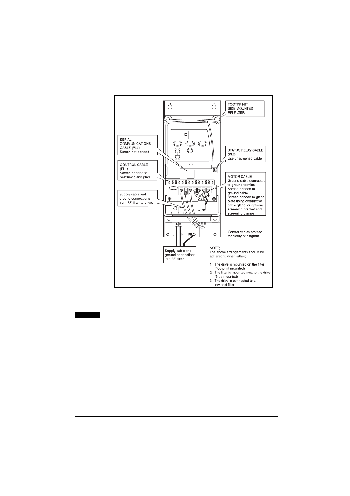
Figure 4.7 Full EMC precautions
NOTE
The above guidelines are applicable to all Drive sizes.
For further information on the cable s creening brackets and screening
clamps kit, refer to the Commander SE Advanced User Guide and the
EMC Data sheets which are available from Control Techniques’ Drive
Centres and Distributors.
Commander SE User Guide
Issue Number 5 29
Page 34
4.5.3 Special requirements
Special considerations are required for the following requirements:
Meeting the residential emission standard, EN50081-1 (Size 1 only)
One of the footprint filters (part number 4200-6102 or 4200-6103) must
be used.
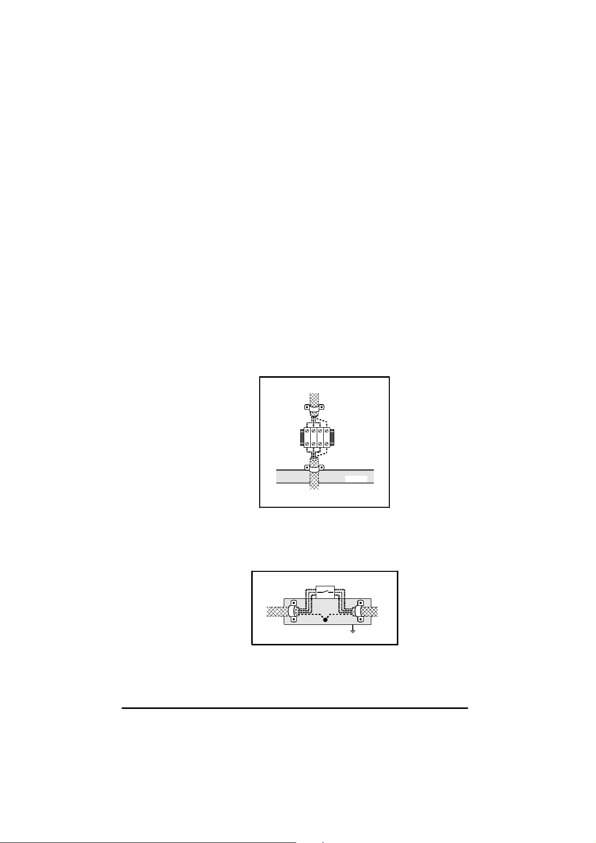
Interruptions to the motor cable
The motor cable should ideally be a single run of shielded cable having
no interruptions. In some situations it may be necessary to interrupt the
cable, for example to connect the motor cable to a terminal block within
thedrive enclosure, orto fitan isolatorswitch to allowsafe workingon the
motor. In these cases both motor cable shield connections must be
clamped directly to the back-plate or other flat metallic structure, as
illustrated in figures 4.8 and 4.9. Keep the length of unscreened power
conductors to a minimum, keep them as close as possible to the metal
plate, and ensure that all sensitive equipment and circuits are at least
0.3m (12in) away from them.
Terminal block within enclosure
RefertoFigure4.8.
From the Drive
Back-plate
Enclosure
To the motor
Figure 4.8 Connecting the motor cable to a terminal block in the
enclosure.
Using a motor isolator switch
RefertoFigure4.9.
Isolator
From the
Drive
Coupling bar
(If required)
To the
motor
Figure 4.9 Connecting the motor cable to an isolating switch.
Commander SE User Guide
30 Issue Number 5
Page 35
4.5.4 RFI filter recommendations and data.
Use one RFI filter for each Drive. Filters of appropriate current rating may
be shared between Drives, but small deviations from the stated
standards may then occur.
The filter performance depends upon the motor cable length and
switchingfrequency.Thefilter performance for themaximum motor cable
length is shown in tables 4.3 to 4.10. For further details on filter
performancewith shorter cable lengths, see the EMC Data sheets which
are available from Control Techniques’ Drive Centres or Distributors.
High ground leakage current
Most RFI filters have ground leakage current exceeding 3.5mA.
All equipment using these filters must be provided with a
WARNING
permanent fixed ground connection.
Special low-leakage filters are provided for applications where a
permanent ground connectionis not practical.
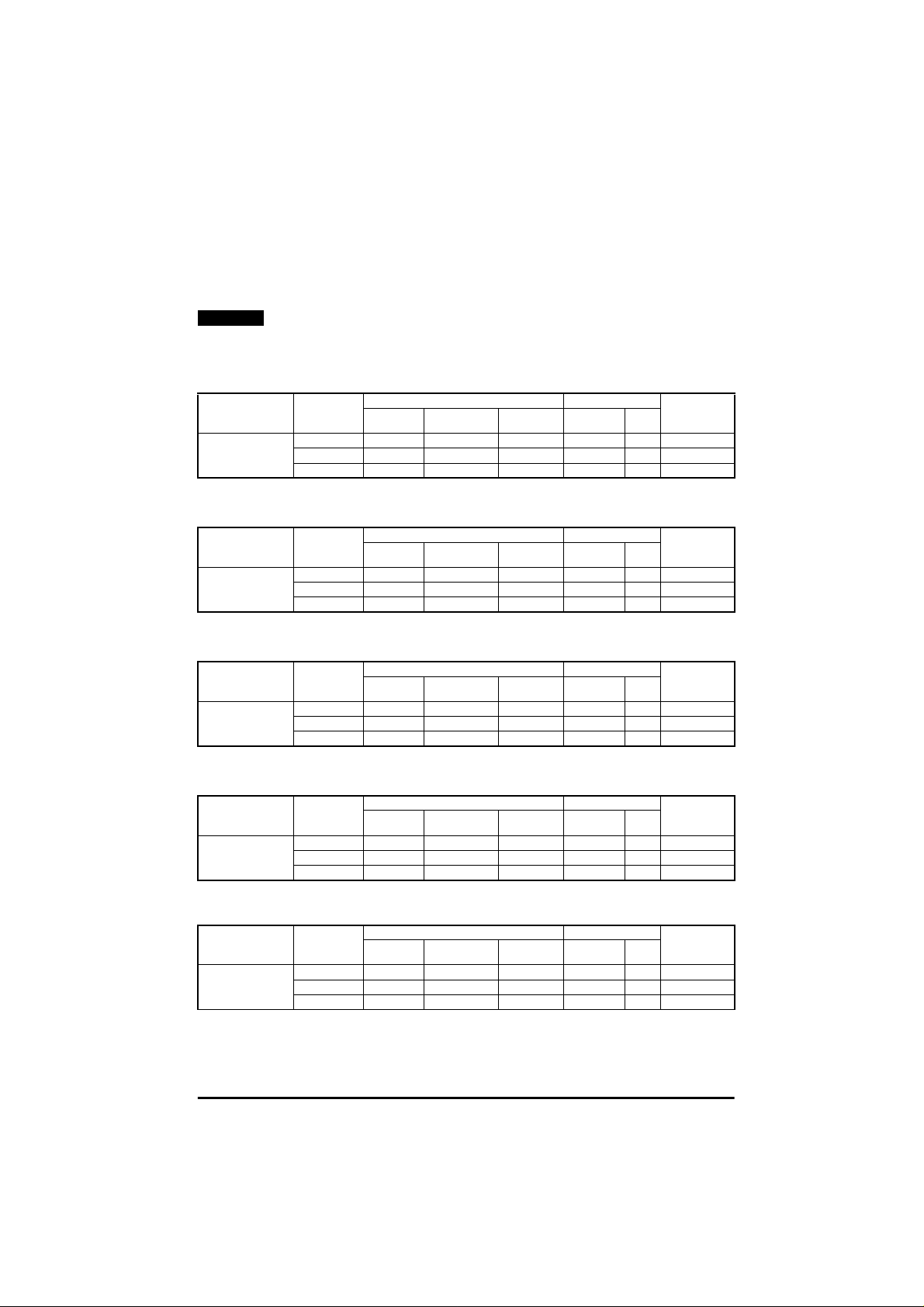
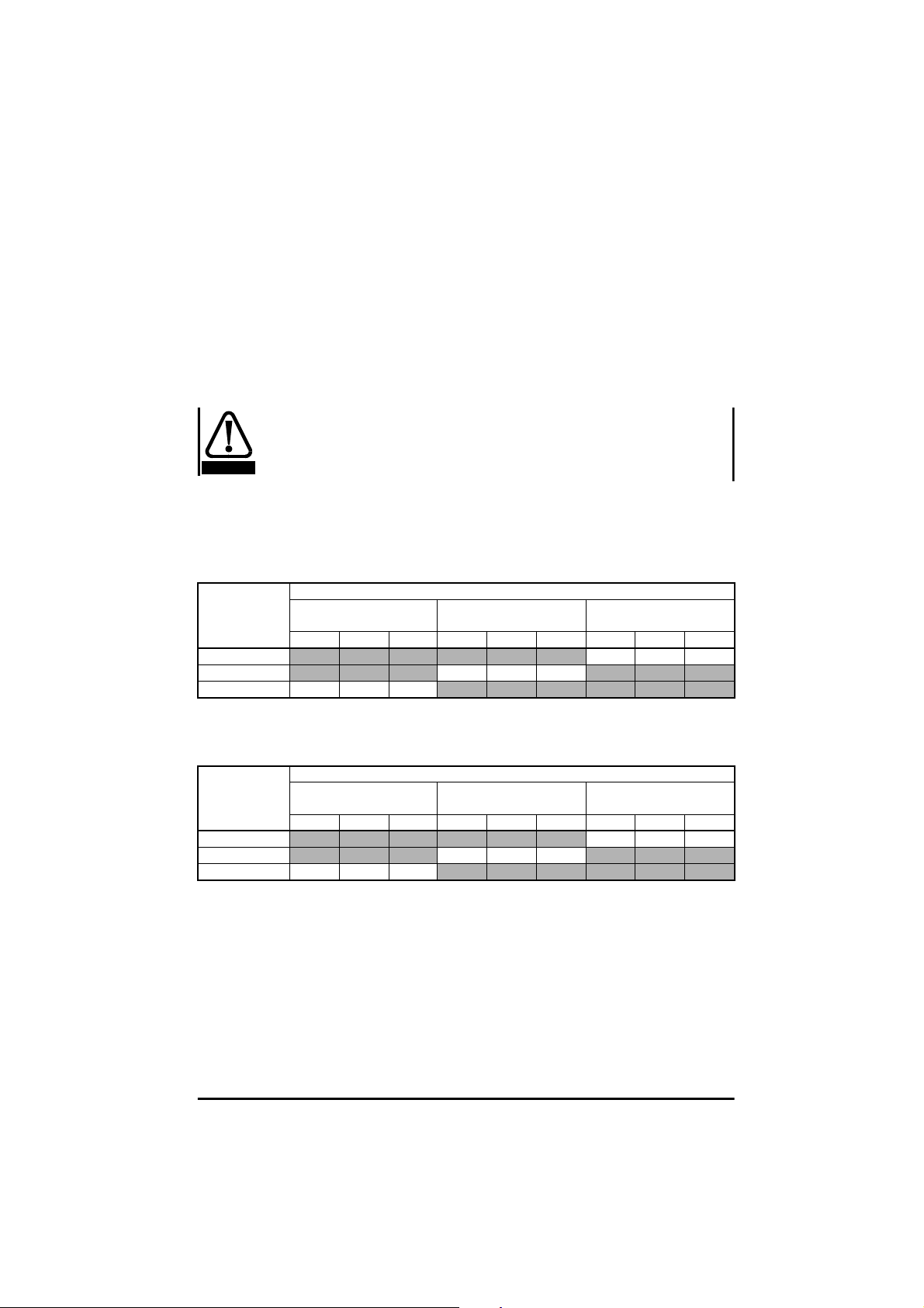
Table 4.3 Commander SE Size 1
Motor cable
length
m
15
20
75 I # #
Standard
(4200-6102)
3kHz 6kHz 12kHz 3kHz 6kHz 12kHz 3kHz 6kHz 12kHz
Filter and Switching Frequency
RR I
Low Cost
(4200-6101)
Low Leakage
(4200-6103)
I##
Commander SE Size 2
Table 4.4 Drive Range: SE2D200075 to SE2D200220, single phase
Motor cable
length
m
15
50
100 I I I
Standard
(4200-6201)
3kHz 6kHz 12kHz 3kHz 6kHz 12kHz 3kHz 6kHz 12kHz
Filter and Switching Frequency
Low Cost
(4200-6204)
I##
Low Leakage
(4200-6205)
II#
Commander SE User Guide
Issue Number 5 31
Page 36
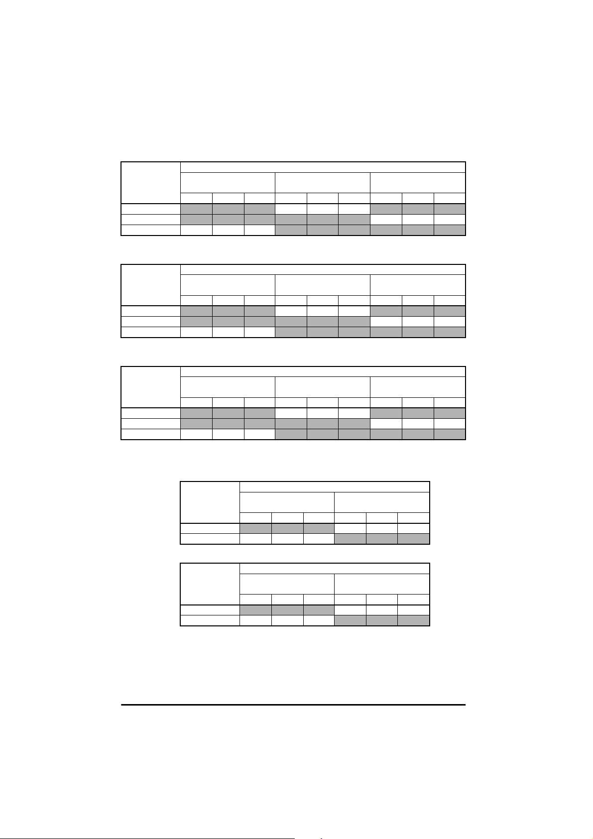
Table 4.5 Drive Range: SE2D200075 to SE2D200220, three phase
Motor cable
length
m
15
45 I##
100 R R I
Standard
(4200-6202)
3kHz 6kHz 12kHz 3kHz 6kHz 12kHz 3kHz 6kHz 12kHz
Filter and Switching Frequency
Low Cost
(4200-6304)
R##
Low Leakage
(4200-6207)
Table 4.6 Drive Range: SE23400075 to SE23400400, three phase
Motor cable
length
m
15
20 I##
100 I # #
Standard
(4200-6202)
3kHz 6kHz 12kHz 3kHz 6kHz 12kHz 3kHz 6kHz 12kHz
Filter and Switching Frequency
Low Cost
(4200-6304)
R##
Low Leakage
(4200-6207)
Table 4.7 Drive Range: SE23200400, three phase
Motor cable
length
m
20
45 I##
100 I # #
Standard
(4200-6203)
3kHz 6kHz 12kHz 3kHz 6kHz 12kHz 3kHz 6kHz 12kHz
Filter and Switching Frequency
Low Cost
(4200-6303)
III
Low Leakage
(4200-6209)
Commander SE Size 3
Table 4.8 Drive Range: SE33200550 to SE33200750
Motor cable
length
m
15
100 I # #
Filter and Switching Frequency
Standard
(4200-6302)
3kHz 6kHz 12kHz 3kHz 6kHz 12kHz
Low Cost
(4200-6303)
II#
Table 4.9 Drive Range: SE33400550 to SE33400750
Motor cable
length
m
15
100 I # #
Filter and Switching Frequency
Standard
(4200-6301)
3kHz 6kHz 12kHz 3kHz 6kHz 12kHz
Low Cost
(4200-6304)
III
Commander SE User Guide
32 Issue Number 5
Page 37
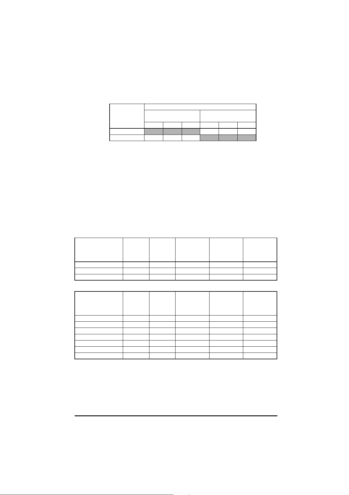
Commander SE Size 4
Table 4.10 Drive Range: SE43401100 to SE43401500
Motor cable
length
m
15
100 I # #
Filter and Switching Frequency
Standard
(4200-6401)
3kHz 6kHz 12kHz 3kHz 6kHz 12kHz
Low Cost
(4200-6402)
I##
Key:
R EN50081-1 Conducted emission requirements of the generic
emission standard for the residential, commercial and light industrial
environment.
I EN50081-2 Conducted emission requirements of the generic
emission standard for the industrial environment.
# Special techniques required e.g. output filters. Contact your Local
Control Techniques Drive Centre.
Further data for the filters is given in the followingtables:
Table 4.11 Commander SE Size 1
Part Number Maximum
Power
Losses
4200-6101 6 21 0.49 4.0 8.0
4200-6102 6 20 0.60 40.7 77.5
4200-6103 6 21 0.60 2.9 5.7
IP Rating Weight
kg
Operational
Leakage
Current
mA
Worst Case
Leakage
Current
mA
Table 4.12 Commander SE Size 2
Part Number Maximum
Power
Losses
4200-6201 10.1 20 1.2 89 128
4200-6202 10.1 20 1.1 45.7 184.2
4200-6203 15.4 20 1.3 26.4 106.3
4200-6204 6 20 0.7 29.5 58.9
4200-6205 10.1 20 1.2 2.8 5.7
4200-6207 10.1 20 1.1 3 18.3
4200-6209 15.4 20 1.3 2.6 15.5
IP Rating Weight
kg
Operational
Leakage
Current
mA
Worst Case
Leakage
Current
mA
Commander SE User Guide
Issue Number 5 33
Page 38
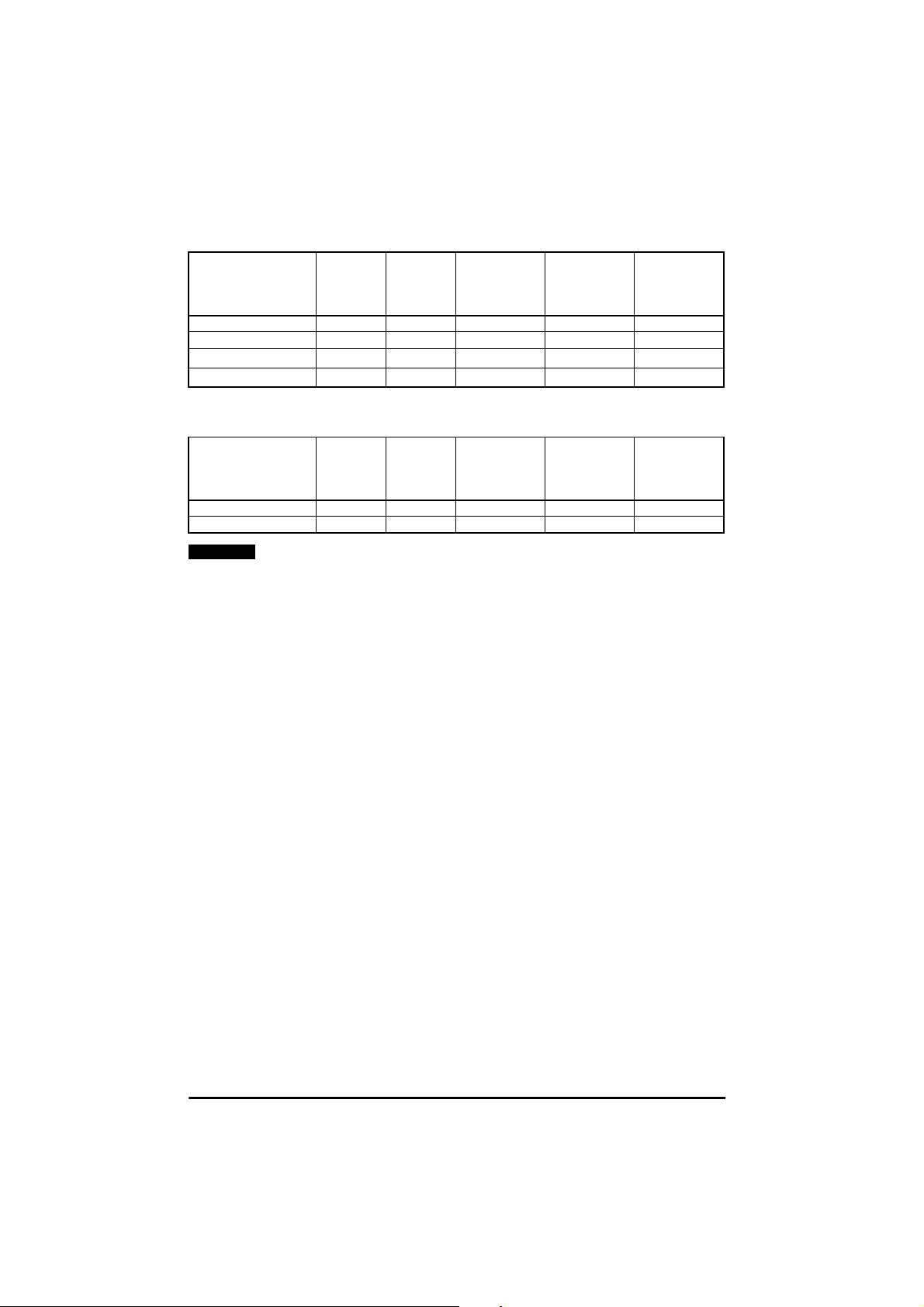
Table 4.13 Commander SE Size 3
Part Number Maximum
Power
Losses
4200-6301 12.4 20 1.6 45.7 184.2
4200-6302 19.5 20 1.7 26.4 106.3
4200-6303
4200-6304
*
*
10.8 20 0.8 14.1 68
6.1 20 0.6 33 148
IP Rating Weight
kg
Operational
Leakage
Current
mA
Worst Case
Leakage
Current
mA
*AlsousedonSize2units.
Table 4.14 Commander SE Size 4
Part Number Maximum
4200-6401 26.1 20 3.1 29.4 280
4200-6402 11.7 20 1.1 14.1 68
NOTE
For tables 4.11 to 4.14, please be aware of the following:
Weight
Power
Losses
is unpacked weight.
Worst case leakage current
IP Rating Weight
kg
:
Operational
Leakage
Current
mA
Worst Case
Leakage
Current
mA
Single phase filters - when the neutral is disconnected.
Three phase filters - when an input phase is disconnected.
The data is given for an input voltage of 230V, 50Hz.
Commander SE User Guide
34 Issue Number 5
Page 39

5 Terminals
y
5.1 Power terminal connections
L1 L2/N PE U V W
Optional
RFI filter
Optional
line reac to r
Fuses
Circuit breaker
/Isola tor
L1 L2/N
Mains
Supply
Figure 5.1 Commander SE Size 1 power terminal connections
+
-
L1
Supply
Ground
L2
Motor
Ground
Motor
L3 PEDBR U V W
Braking
Resistor
Thermal
protection
device
Stop
Start/
Reset
Optional
Optional RFI
filter
Optional
line reactor
L1 L2
Mains
Suppl
Motor
Ground
Fuses
Motor
L3
Supply
Ground
Figure 5.2 Commander SE Size 2 to 4 power terminal connections
NOTE
Whena Commander SE Size 2 200 volt unit is used on single phase,
use terminals L1 and L2.
Drive Size Maximum Power Terminal Screw
Torque
Nm lb in
1&2 1 9
3&4 2 18
Commander SE User Guide
Issue Number 5 35
Page 40
5.1.1 Thermal protection for an optional braking resistor
Figure 5.2 shows a typical circuit arrangement for braking
resistor protection. This thermal protection must disconnect
the AC supply from the Drive if the resistor becomes
WARNING
overloaded. (Do not use overload opening contact in line with
braking resistor).
For further information on braking and braking resistor sizing, refer to the
Commander SE Advanced User Guide
.
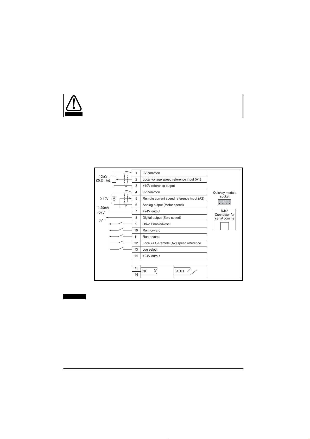
5.2 Control terminal connections
The terminal connectionsare shown in Figure 5.3. As default - in positive
logic. Maximum control terminal screw torque: 0.6 Nm (5.5 lb in)
Figure 5.3 Control terminal c onnections
NOTE
The connection arrangement shown here illustrates how the
terminals are intended to be used. Screening of the analog signal
wires is not essential, but reduces the risk of electrical noise
causing disturbance to the signals.
Where full EMC precautions are required, the guidelines in section
4.5.2 must also be followed to ensure compliance with radio
frequency emission limits. This requires the use of one or more
screened cables for all wiring to terminals 1 to 14, with the screen
Commander SE User Guide
36 Issue Number 5
Page 41

bonded to the gland plate (ground). This results in the 0V common
terminal being connected to ground through the cable screen.
Where it is required to keep 0V separate from ground, there are two
possibilities:
• Use a multi-core cable with overall screen, using one core for
the 0V c onnection. There is a slight risk of electrical noise
affecting the analog inputs.
•
Use a double screened cable for the analog inputs, with the
inner screen connected to 0V and the outer screen to ground
5.3 Serial communication connections
Serial communicationconnections can be made via the RJ45 connector
(see Figure 5.3).
PIN 2 RXTX
PIN 3 0V
PIN 4 +26V (+10% / -7%) 100mA serial communications
PIN 6 TX Enable
PIN 7 RX\TX\
Whenusinga suitable serialcommunicationsconverter with Commander
SE, it is recommended that no terminatingresistors be connected on the
network. This applies to any of the Drives on the network and also any
converter used. It may be necessary to link out the terminating resistor
within the converter, depending on which type is used. The information
onhowto linkout the terminatingresistor willnormallybe contained in the
userinformation suppliedwith the converter.Terminating resistors are of
little or no value when used on RS485 networks operating at or below
19.2KBaud.
For further information, refer to the
.
Guide
Commander SE Advanced User
.
The communications port of the Commander SE drive is
double-insulated and meets the requirements for SELV
(Safety Extra Low Voltage) in EN50178. However, in the
WARNING
event of a serious fault in the Drive the safety barriers
could be breached. Therefore when using the
communications port with a personal computer or
centralised controlle r e.g. PLC, an isolation device mustbe
included with rated voltage at least equal to the Drive
supply voltage. Ensure that the correct fuses are installed
at the Drive input, and that the Drive is connected to the
correct supply voltage.
Commander SE User Guide
Issue Number 5 37
Page 42

5.4 Control terminal specifications
Isolation of control circuits
The control terminals of the Commander SE drive are double-
WARNING
insulated and meet the requirements for SELV (Safety Extra
Low Voltage) in EN50178. However, in the event of a serious
fault in the Drive the safety barriers could be breached. The
installer must ensure that the external control circuits are
insulated from human contact by at least one layer of
insulation rated for use at the AC supply voltage. If the control
circuitsare to be connected to othercircuits classified as SELV
e.g. a personal computer, an additional isolating barrier must
be included in order to maintain SELV classification. Ensure
that the correct fuses are installed at the Drive input, and that
the Drive is connected to the correct supply voltage.
5.4.1 Default configuration
All outputs (+24, +10V, Digital output and Analog output) could
be permanently damaged if a negative voltage greater than -1V
is applied to them.
CAUTION
1 0V common
2 Local Speed reference input (A1)
Type of input Single-ended
Voltagerange 0 to +10V
Scaling 0V represents the value in parameter
Absolute maximum voltage range +35V to -18V with respect to 0V
Input impedance 100k
Resolution 0.1% (10 bit)
Accuracy
Sample time 6ms
01, Minimum speed.
+10V represents the value in
parameter 02, Maximum speed.
common
Ω
±
2%
3 +10V reference output
Voltage accuracy
Maximum output current 5mA
Protection tolerates continuous s hort circuit to
4 0V common
±
0V
2%
Commander SE User Guide
38 Issue Number 5
Page 43

5 Remote current speed-reference input (A2)
Default 4 - .20mA (See parameter 16)
Type of input Single ended
Current range (programmable) 0-20mA, 20-0m A, 4-20mA, 20-4mA,
Absolute maximum voltage range +35Vto -18V with respect to 0V
Input impedance 200
Resolution 0.1% (10 bit)
Accuracy
Sample time 6ms
6 Analog voltage output
Default Motor Speed (See parameter 36)
Absolute maximum voltage range +35V to -1V with respect to 0V
Voltagerange 0 to +10V
Scaling: Motor speed output
% full load current output
Maximum output current 5mA
Resolution 0.1% (10 bit)
Accuracy
Update time 22ms
Protection tolerates continuous short circuit to 0V
4-.20mA, 20-.4mA
common
Ω
±
2%
common
0V represent 0Hz/0 rpm output
+10V represents the value of
parameter 02, Maximum speed.
0V represent 0% Drive rated current
+10V represents 150% Drive rated
current.
±
5%
7 +24V output
Voltage accuracy
Maximum output current 100mA
Protection tolerates continuous short circuit to 0V
8 Digital output
Function Zero Speed Output
Absolute maximum voltage range +35V to -1V with respect to 0V
Voltagerange 0V to +24V
Maximum output current 50mA at +24V
Output impedance 10kΩpull-down resistor in inactive
Update time 1.5ms
Operation of digital output +24V = Zero speed
±
10%
common
state.
0V = Above zero speed
Commander SE User Guide
Issue Number 5 39
Page 44

NOTE
The total c urrent available from the +24V rail, which includes the
digital output, is 100mA. Therefore if the digital output is providing
30mA, the +24V rail will only provide 70mA.
9
10
11
12
13
Digital input - Enable / Reset †
Digital input - Run Forward (Edge triggered) *
Digital input - Run Reverse (Edge triggered) *
Digital input - Local/Remote Speed Ref (A1/A2)
Digital input - Jog
Default Positive logic (See parameter 34)
Voltagerange 0V to +24V
Absolute maximum voltage range +35V to -18V with respect to 0V
common
Nominal threshold voltage +10V
Input impedance 7.5k
Ω
Sample time 1.5ms
If the enable terminal is opened, the Drive’s output is disabled and the motor will coast to a
stop. The Drive cannot be re-enabled for 2 seconds following the opening of the enable
terminal.
† Following a Drive trip, op en and close the Enable terminal to reset the Drive. If the Run
Forward or Run Reverse terminal is closed, the Drive will run straight away.
* Following a Drive trip and a reset via the Stop/Reset key the Run Forward or Run Reverse
terminals will need to be opened and closed to allow the Drive to run. This ensures that the
Drive does not start when the Stop/Reset key is pressed.
14 +24V output
Voltage accuracy
±
10%
Maximum output current 100mA
Protection toleratescontinuous short circuitto
0V
15
Status relay (Normally open)
16
Function Drive Healthy
Voltagerating 240VAC /30VDC
Current rating 2A/6A (resistive)
Contact isolation 2.5kVAC (meets IEC664-1 with
over voltage category II)
Update time 6ms
Operation of contact OPEN
- AC supply removed from Drive
- AC supply applied to Drive with
the Drive in a tripped condition
CLOSED
- AC supply applied to Drive with
the Drive in a ‘ready to run’ or
‘running’ condition (not tripped)
Commander SE User Guide
40 Issue Number 5
Page 45

WARNING
Provide fuse or other over-current protection in status relay
circuit.
Commander SE User Guide
Issue Number 5 41
Page 46

6 Handling and Programming
6.1 Display and keypad
The display and keypad are used for the following:
• Displaying the operating status of the Drive
• Displaying fault or trip codes
• Reading and changing parameter values
• Stopping, starting and resetting the Drive
Sign LED
Figure 6.1 Display and Keypad (as seen when the AC supply is
connected to the Drive)
6.1.1 Programming keys
The MODE key is used to change the mode of operation of the
display.
If the MODE key is pressed and then released within 2 seconds, the
display will change from Status Mode to Parameter View Mode.
If the MODE key is pressed and held down for 2 seconds then the Status
Modewill changefrom speed indicationto loadindication and vice versa.
See Parameters 22 and 23.
The Drive will remember the displayedunits on power down (speed or
load) such that the same units are presented on the next power up.
The INCREASE & DECREASE keys are used to select
parametersand edit their values. Also, in keypad mode,they are used to
increase and decrease the speed of the motor.
Display
Control Keys
Programming
keys
Commander SE User Guide
42 Issue Number 5
Page 47

6.1.2 Control keys
The RUN key is used in keypad mode, to START the Drive.
The STOP/RESET keyisusedinkeypadmode,toSTOP and
RESET the Drive. It can also reset the Drive in terminal control.
The FORWARD/REVERSE key is used in keypad mode to change
direction of rotation of the motor (when parameter 26=On).
6.2 Display Messages
6.2.1 Status mode
In status mode, left hand display indicates a two letter mnemonic
indicating the status of the Drive:
Display Status Explanation
rd Drive ready The Drive is enabled and ready for a start
ih Drive inhibited The output bridge is inactive becaus e t he
tr Drive has tripped The Drive has received a trip signal. (The trip
dC DC injection braking DC injection braking current is being applied
command. The output bridge is inactive.
Drive is disabled, or a coast to stop is in
progress, or the Drive is inhibited during a trip
reset.
code will be displayed in the right hand
display).
to the motor.
Load indications - see parameter 22
Display mnemonic Explanation
Ld Output current as a % of rated motor load
A Drive output current per phase in Amps
Speed indications - see parameter 23
Display mnemonic Explanation
Fr Drive output frequency in Hz
SP Motor speed in RPM
Cd Machine speed in Customer defined units
NOTE
The frequency or speed on the display is the post ramp reference. It
does not include slip compensation, if applied.
Commander SE User Guide
Issue Number 5 43
Page 48
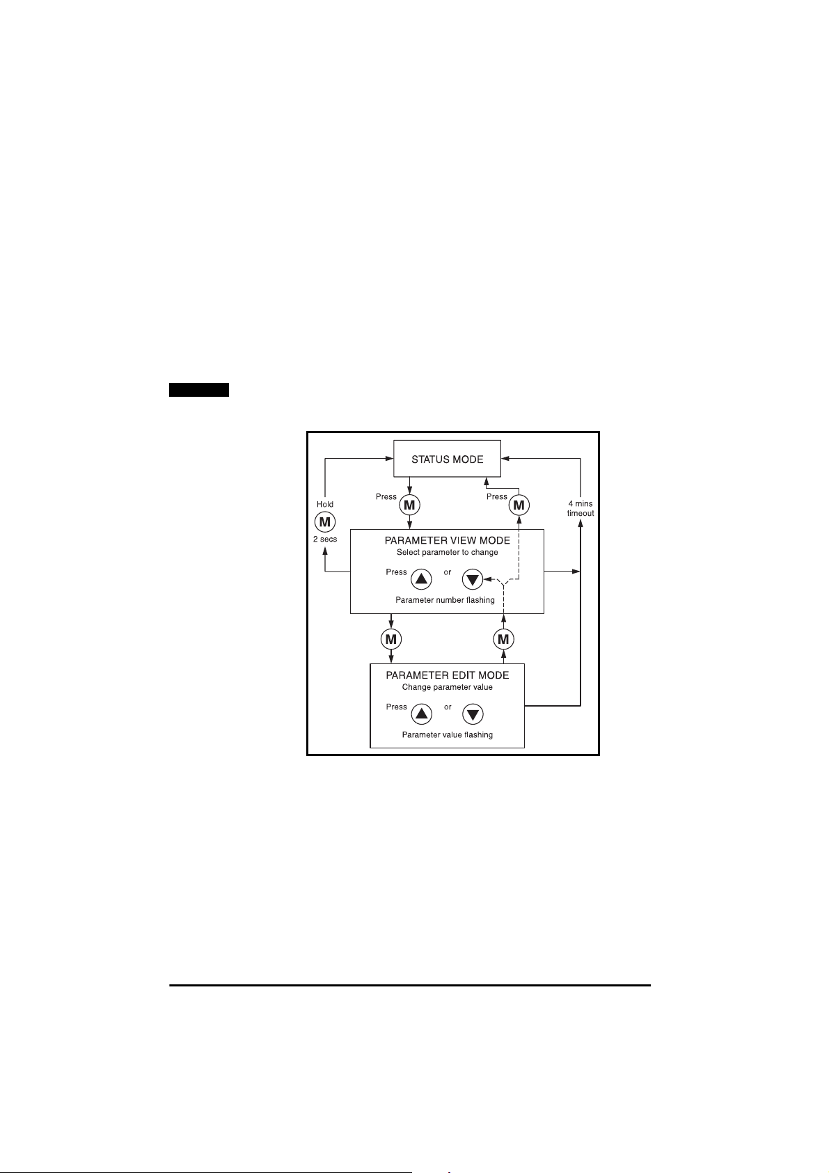
6.2.2 Parameter View Mode
In parameter view mode, the left hand display flashes a parameter
number. The right hand display s hows the value of that parameter.
6.2.3 Parameter Edit Mode
In parameter edit mode, the right hand display flashes the value of the
parameter number which is being shown in the left hand display.
The following diagram and procedure shows how to selectand then edit
parameters:
6.3 Selecting and changing parameters
NOTE
This procedure is written from the first power up of the Drive and
assumes no terminals have been connected, no parameters have
been changed and no security has been set.
Figure 6.2 Selecting and changing parameters
Commander SE User Guide
44 Issue Number 5
Page 49
6.4 Saving parameters
Parameters are automatically saved when the mode button is pressed
when going from parameter edit mode to parameter view mode.
6.5 Security codes
A security code is locked into the Drive when parameter 25 is set to any
value other than 0 and then Loc is selected in parameter 10 and the
STOP/RESET key pressed.
Once a security code has been locked, parameter 10 will automatically
reset to L1. Now view only access to parameters 1 to 9 is available.
Parameter 10 may be changed by the user to L2 to allow view only
access to all the parameters (1 to 44). In this case, parameter 2 5 will
indicate a value of 0 so as not to reveal the programmed security code.
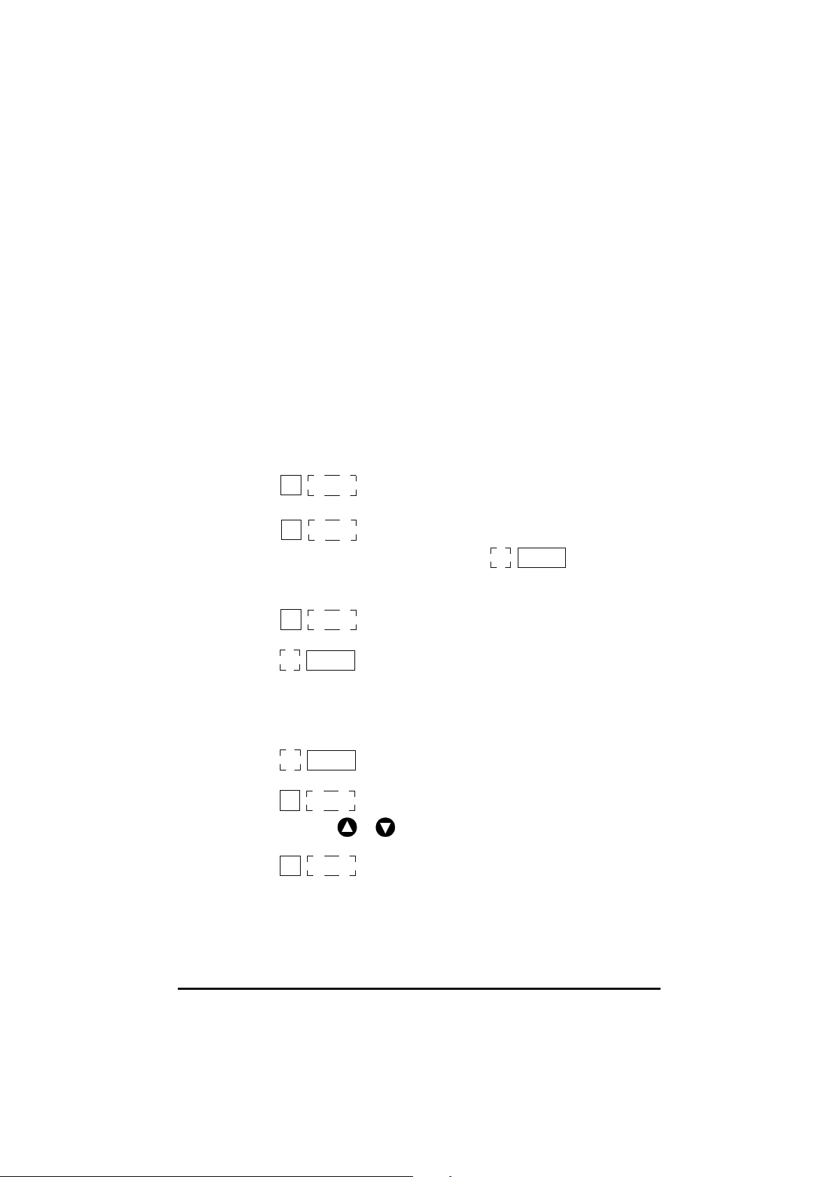
6.6 Setting a security code
1. Set parameter 10 to L2 to allow access to parameter 25.
10
2. Set parameter 25 to a security code e.g. 5.
25
L2
5
This code changes to 0 once the MODE key is
pressed. The display should show:
3. Set parameter 10 to Loc and then press the STOP/RESET key to
initiate the security code
10
4. Parameter 10 will automatically reset to L1
10
5. Security will also be set if the Drive is powered down after a code
has been set into parameter 25.
6.7 Unlocking a security code
1. Select a parameter to be edited
01
2. Press the MODE key. The right hand display will flash CodE
01
3. Press the or keys to set the security code. The left hand
display will show Co
Co
4. Press the MODE key.
Loc
L1
0.0
CodE
5
25
0
Commander SE User Guide
Issue Number 5 45
Page 50

5. If the security code has been entered correctly then the display will
show
01
6. If the security code has been entered incorrectly then the display will
go back to Parameter View mode
01
7. Go back to point 2 and enter the correct security code.
8. To relock the security code, set parameter 10 to Loc and press the
STOP/RESET key.
10
6.8 Set security back to zero (0) - no security
1. Unlock the previously entered security code using the previous
procedure.
2. Set parameter 10 to L2.
3. Go to parameter 25
4. Press mode key 4 times. This saves the securitycode to the value 0
5. Set parameter 10 to Loc and press the STOP/RESET key.
NOTE
If the security code has been lost or forgotten, please contact your
0.0
Parameters can now be adjusted
0.0
Loc
local Drive Centre or Distributor.
6.9 Setting to default values
To set the Drive back to default values, set parameter 29 to Eur to load
50Hz defaults or USA to load 60Hz defaults. Press the MODE key and
then the STOP/RESET key for 1 second. When the default parameters
have been set, the display will show the status of the Drive and the
parameter number will return to 01.
6.10 Level 1 and level 2 parameter descriptions
6.10.1 Parameter codes/limitations
The key to the parameter codes/limitations in the following Tables is
listed below:
1 RW R
2 RO R
3 Bit Two state only parameter, OFF or ON
4 B Bipolar - can have positive or negative values
5 U U
6 T Parameter value is represented on the display with a
7 R R
8 S S
ead/Write
ead Only
nipolar - can have positivevalues only
string of Text
eset required to implement change
aved on power down
Commander SE User Guide
46 Issue Number 5
Page 51
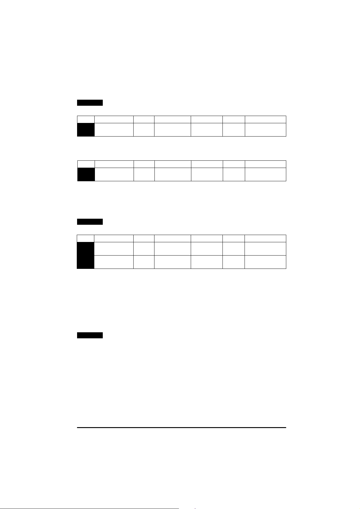
6.10.2 Level 1 parameters
NOTE
Text after a block of parameters refers to the preceeding
parameter(s).
No. Function Type Limitations Range Units Defaults
01 Minimum speed RW U 0- parameter02Hz 0.0 EUR
0.0 USA
Used to set minimum speed at which the motor will run.
(0V reference or minimum scale current input [see parameter 16]
represents the value in parameter 01).
No. Function Type Limitations Range Units Defaults
02 Maximum
speed
RW U 0 - 1000 Hz 50.0 EUR
60.0 USA
Sets the maximum speed at which the motor will run in both directions of
rotation. If parameter 02 is set below parameter 01, parameter 01 is
automaticallyset to the new value of parameter 02. (+10V reference or
full scale current input [see parameter 16] represents the value in
parameter 02).
NOTE
The output speedof the Drivecan exceedthe value set in parameter
02 due to slip compensation and current limits.
No. Function Type Limitations Range Units Defaults
03 Acceleration
rate
04 Deceleration
rate
RW U 0.0-3200.0 Secs/
100Hz
RW U 0.0-3200.0 Secs/
100Hz
5.0 EUR
5.0 USA
10.0 EUR
10.0 USA
Sets the acceleration and decelerationrate of the motor for both
directions of rotation.
The acceleration rate corresponds to the time to accelerate from 0 to
100Hz. Therefore, with a programmed ramp time of5 seconds,the ramp
output will reach 50Hz from 0Hz in 2.5 seconds.
The deceleration rate corresponds to the time to decelerate from 100 to
0Hz. Therefore, with a programmed ramp time of 10 seconds, the ramp
output will reach 0Hz from 50Hz in 5 seconds.
NOTE
The deceleration rate could be extended by the Drive to prevent
over voltage (OU) trips if the load inertia is too high for the
programmed deceleration rate, if one of the standard ramp modes
is selected - parameter 30.
Commander SE User Guide
Issue Number 5 47
Page 52

No. Function Type Limitations Range Units Defaults
05 Speed
reference
select
RW T A1.A2,A1.Pr,
A2.Pr,Pr,PAd
A1.A2 EUR
PAd USA
The setting of parameter 05 will select the type of speed reference input
and also the functionof the digital inputs on terminal 12 and 13.
Parameter 05 settings:
• A1.A2 - Analog voltage input on terminal 2 and analog current input
on terminal 5 selected by terminal 12. Jog selected by terminal 13
• A1.Pr - Analog voltage input on terminal 2 and 3 preset speeds
selected by terminals 12 and 13
• A2.Pr - Analog current input on terminal 5 and 3 preset speeds
selected by terminals 12 and 13
• Pr - 4 Preset speeds selected by terminals 12 and 13
• PAd - keypad control
NOTE
PAd- Keypadreference selected. Terminals10, 11, 12 and 13 do not
have any function in this mode.
The settings for parameter 05 are explained fully on the following pages.
Commander SE User Guide
48 Issue Number 5
Page 53
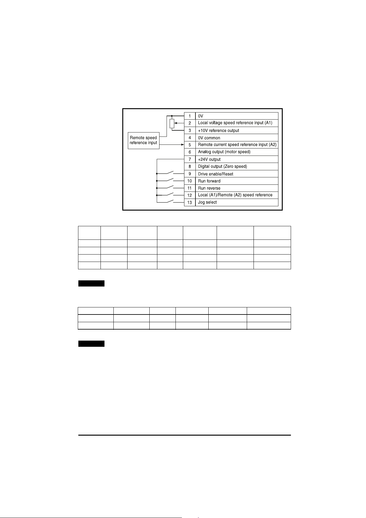
Parameter 5 set to A1.A2
Local voltage (A1) or remote current (A2) speed reference inputs
Figure 6.3 Terminal connections
Input
Source
NOTE
Terminal12Terminal13Enable Run Forward Run Reverse Motor Action
A1 open open closed closed open Run Forward
A1 open open closed open closed Run Reverse
A2 closed open closed closed open Run Forward
A2 closed open closed open closed Run Reverse
If the Run Forward and Run Reverse terminals are both closed, the
Drive will stop under the selected ramp and stopping modes.
Jog speed reference (parameter 15)
Terminal 12 Terminal 13 Enable Run Forward Run Reverse Motor Action
open or closed closed closed closed open Jog Forward
open or closed closed closed open c losed Jog Reverse
NOTE
If jog speed is selected during normal running, the motor will
accelerate or decelerate to the jog speed at the normal acceleration
ramp (parameter 03) or deceleration ramp (parameter 04) and then
the jog acceleration and deceleration ramps (0.2 seconds) will be
selected. Once jog has been selected use the Run Forward or Run
Reverse terminals to jog.
Commander SE User Guide
Issue Number 5 49
Page 54
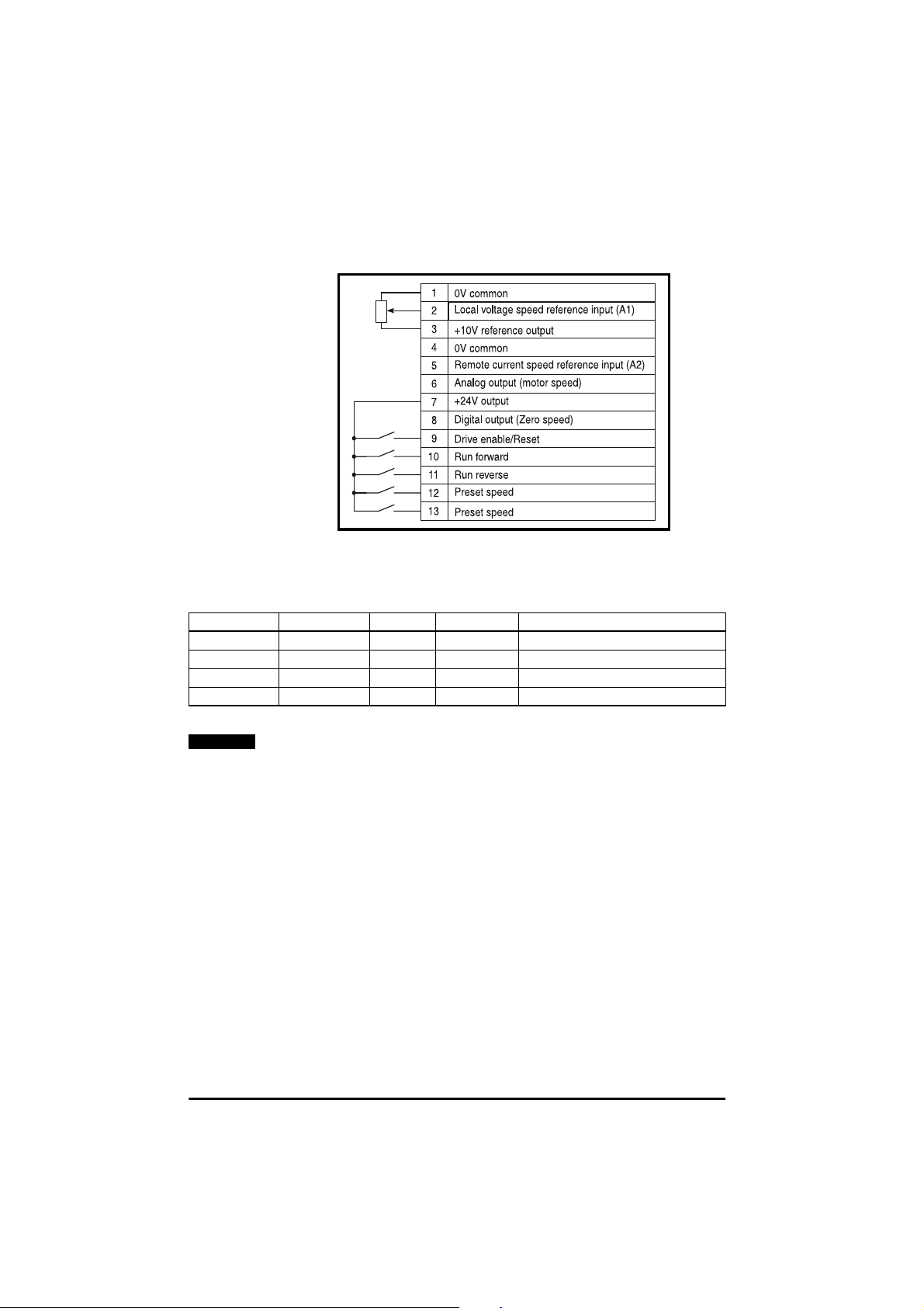
Parameter 5 set to A1.Pr
Local voltage (A1) speed reference input with 3 preset speeds
Figure 6.4 Terminal connections
Close terminals 12 and 13 as in the following table to select the desired
preset speed.
Terminal 12 Terminal 13 Enable Run Forward Speed reference
open open closed closed Local speed ref. (A1)
closed open closed closed Preset speed 2 (parameter 12)
open closed closed closed Preset speed 3 (parameter 13)
closed closed closed closed Preset speed 4 (parameter 14)
NOTE
If Enable negative preset speeds (parameter 17) is set, then a
negative preset speed will cause the motor to run in the reverse
direction. Alternatively, closing terminal 11 (Run Reverse) instead
of terminal 10 will change the sign of the selected speed such that
a positive preset speed will become negative for reverse rotation.
Commander SE User Guide
50 Issue Number 5
Page 55
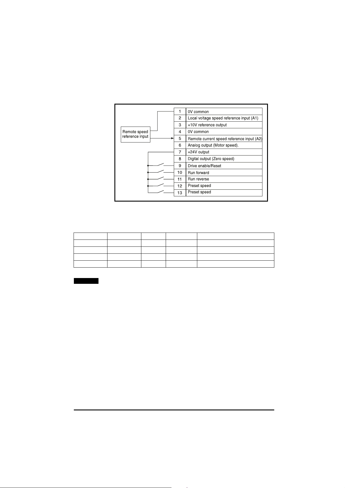
Parameter 5 set to A2.Pr
Remote current (A2) speed reference input with 3 preset speeds.
Figure 6.5 Terminal connections
Close terminals 12 and 13 as in the following table to select the desired
preset speed.
Terminal 12 Terminal 13 Enable Run Forward Reference
open open closed closed Remote speed ref. (A2)
closed open closed closed Preset speed 2 (parameter 12)
open closed closed closed Preset speed 3 (parameter 13)
closed closed closed closed Preset speed 4 (parameter 14)
NOTE
If Enable negative preset speeds (parameter 17) is set, then a
negative preset speed will cause the motor to run in the reverse
direction. Alternatively, closing terminal 11 (Run Reverse) instead
of terminal 10 will change the sign of the selected speed such that
a positive preset speed will become negative for reverse rotation.
Commander SE User Guide
Issue Number 5 51
Page 56
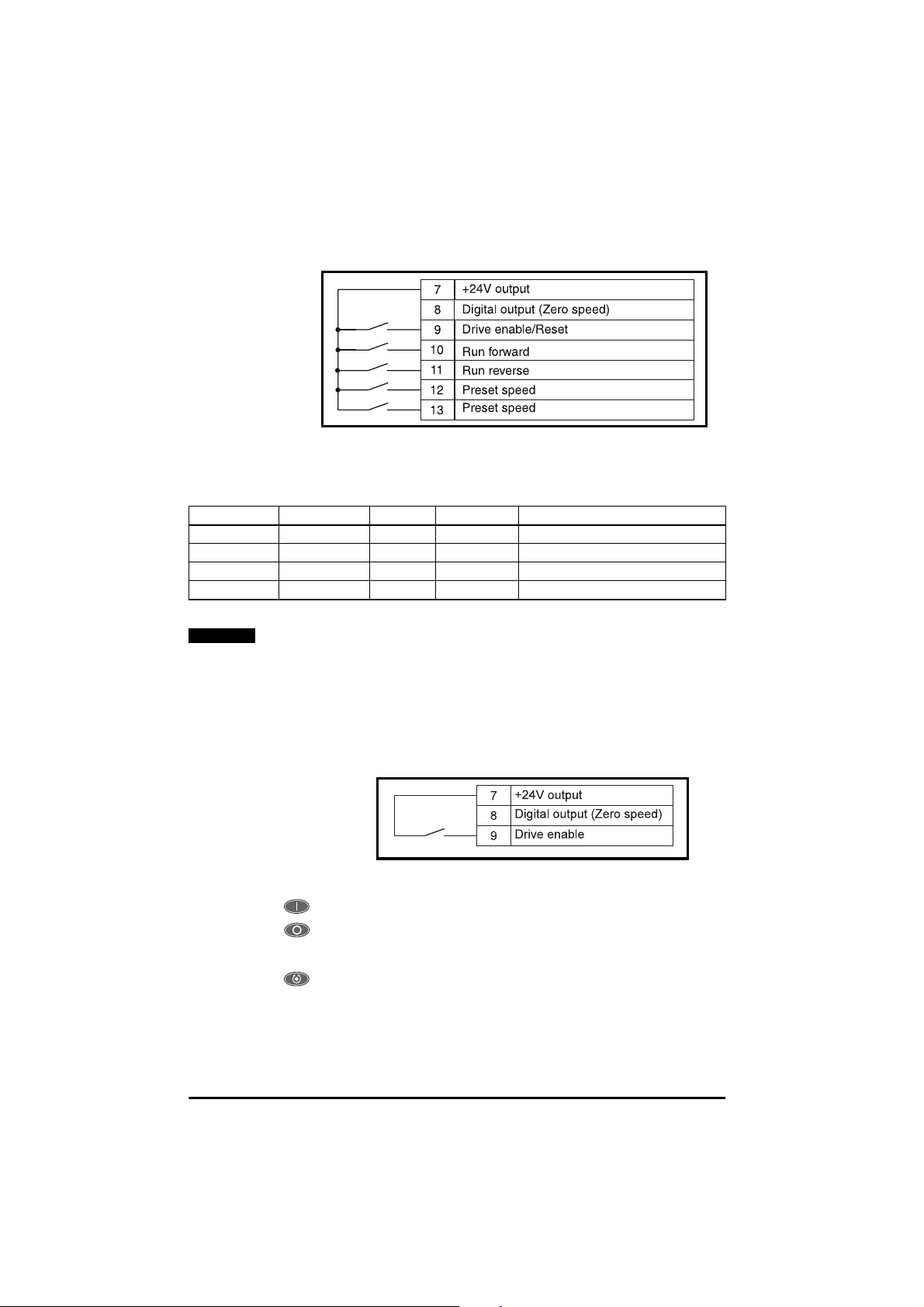
Parameter 5 set to Pr
4 Preset speeds
Figure 6.6 Terminal connections
Close terminals 12 and 13 as in the following table to select the desired
preset speed.
Terminal 12 Terminal 13 Enable Run Forward Speed Reference
open open closed closed Preset speed 1 ( Parameter 11)
closed open closed closed Preset speed 2 (Parameter 12)
open closed closed closed Preset speed 3 (Parameter 13)
closed closed closed closed Preset speed 4 (Parameter 14)
NOTE
If Enable negative preset speeds (parameter 17) is set, then a
negative preset speed will cause the motor to run in the reverse
direction. Alternatively, closing terminal 11 (Run Reverse) instead
of terminal 10 will change the sign of the selected speed such that
a positive preset speed will become negative for reverse rotation.
Parameter 5 Set to PAd
Keypad control
Figure 6.7 Keypad connections
Used to start the Drive.
Used to stop the Drive. Also used to reset the Drive after a trip.
After a reset command, the Drive will need a start command to run.
Used to reverse the direction of rotation of the motor
(when parameter 26 = On).
Commander SE User Guide
52 Issue Number 5
Page 57
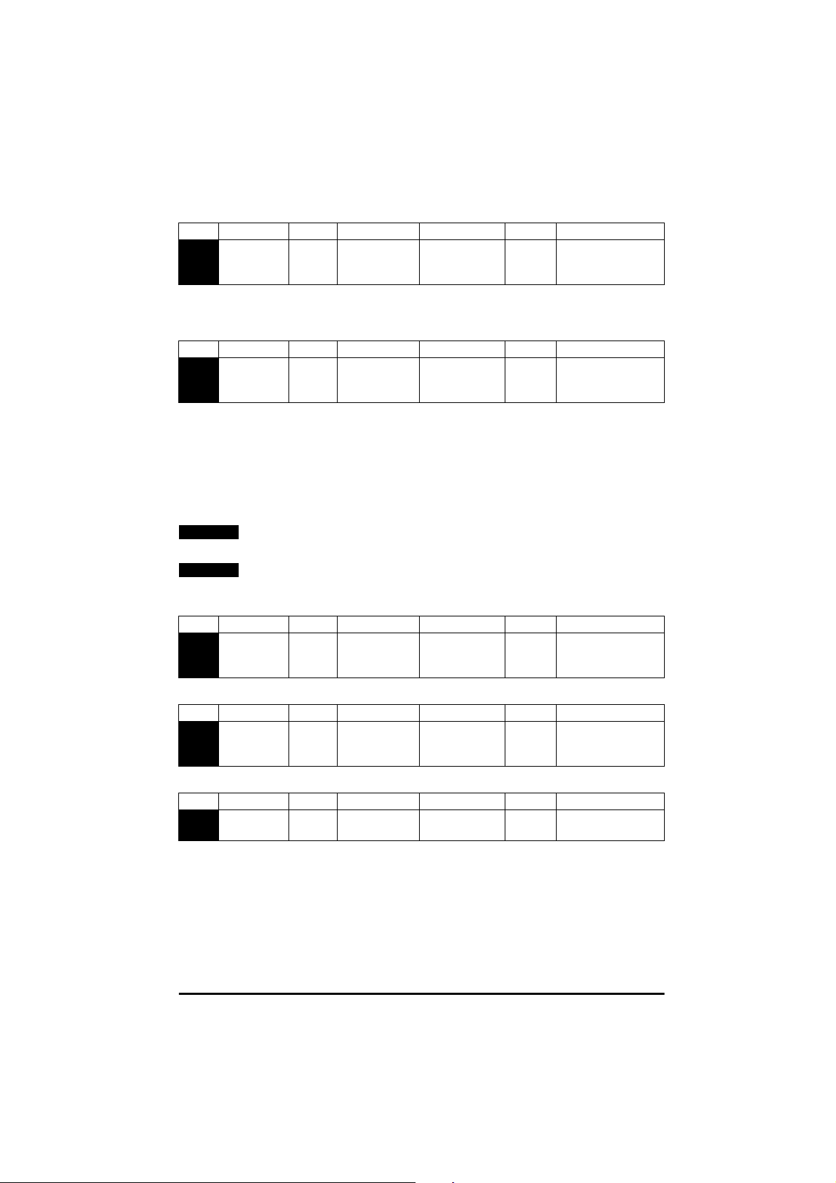
No. Function Type Limitations Range Units Defaults
06 Motor
rated
current
RW U 0 - Drive rated
current
A Drive rating EUR
Drive rating USA
Enter the motor current rating (taken from the motor name plate).
The Drive rated current value is the 100% RMS output current value of
the Drive. This value can set to a lower value but not a higher value.
No. Function Type Limitations Range Units Defaults
07 Motor
rated
speed
RW U 0 - 99 99 rpm 1500 EUR
1800 USA
Enter the rated full load speed of the motor (taken from the motor name
plate).
The rated speed is used to calculate the correct slip for the motor.
The rated speed is the synchronous speed - the 100% full load slip of the
motor.
Example: For a 4 pole motor with a synchronous speed of 1500rpm and
a slip speed of 70rpm, enter 1430rpm in parameter 07.
NOTE
A value of zero entered into parameter 07 means slip compensation
is disabled.
NOTE
If the full load speed of the motor is above 9999rpm,enter a value of
0 in parameter 07. This will disable slip compensation as values
greater than 9999 cannot be entered into this parameter.
No. Function Type Limitations Range Units Defaults
08 Motor
rated
voltage
RW U 0 - 240
0 - 480
V 230/400 EUR
230/460 USA
Enter the motor rated voltage (taken from the motor name plate).
No. Function Type Limitations Range Units Defaults
09 Motor
power
factor
RW U 0 - 1.00 0.85 EUR
0.85 USA
The motor power factor cos ϕ (taken from the motor name plate).
No. Function Type Limitations Range Units Defaults
10 Parameter
access
RW T L1, L2, Loc L1 EUR
L1 USA
L1 - Level 1access - Only parameters1 to10 canbe selectedfor viewing
or adjusting.
L2 -Level2access-Allparameters1to44canbeselectedforviewing
or adjusting.
Loc - Used to lock a security code in the Drive. See
Security codes
in
Section 6.5.
Commander SE User Guide
Issue Number 5 53
Page 58

6.10.3 Level 2 parameters
No. Function Type Limitations Range Units Defaults
11 Preset 1 RW B ±1000.0 Hz 0.0 EUR
0.0 USA
Defines the preset speed 1.
For setting of negative preset speed values, see parameter 17.
No. Function Type Limitations Range Units Defaults
12 Preset 2 RW B ±1000.0 Hz 0.0 EUR
0.0 USA
Defines the preset speed 2.
For setting of negative preset speed values, see parameter 17.
No. Function Type Limitations Range Units Defaults
13 Preset 3 RW B ±1000.0 Hz 0.0 EUR
0.0 USA
Defines the preset speed 3.
For setting of negative preset speed values, see parameter 17.
No. Function Type Limitations Range Units Defaults
14 Preset 4 RW B ±1000.0 Hz 0.0 EUR
0.0 USA
Defines the preset speed 4.
For setting of negative preset speed values, see parameter 17.
No. Function Type Limitations Range Units Defaults
15 Jog
reference
RW U 0 - 400.0 Hz 1.5 EUR
1.5 USA
Defines the jog speed.
Commander SE User Guide
54 Issue Number 5
Page 59

No. Function Type Limitations Range Units Defaults
16 Current
input
mode
RW T 0-20, 20-0
4-20, 20-4
4-.20, 20-.4
mA 4-.20 EUR
4-.20 USA
Defines the current input on Analog input reference 2, terminal 5.
Definition of the current input mode is given in the following sub-table:
Mode D escription
0 - 20 Current input 0 to 20mA (20mA full sc ale)
20 - 0 Current input 20mA to 0mA (0mA full scale)
4 - 20 Current input 4mA to 20mA with current loop loss (cL) trip (20mA full scale)
20 - 4 Current input 20mA to 4mA with current loop loss (cL) trip (4mA full scale)
4 - .20 Current input 4m A to 20m A with no current loop loss (cL) trip (20mA full scale)
20 - .4 Current input 20mA to 4mA with no current loop loss ( cL) trip (4mA f ull scale)
In the 4-20mA or 20-4mA ranges with current loop loss (cL) trip, the Drive
will trip on cL if the input reference is less than 3mA.
NOTE
If 4-20mA or 20-4mA modes are selected and the Drive trips on
current loop loss (cL), analog reference 1 cannot be selected if the
current reference is less than 3mA.
No. Function Type Limitations Range Units Defaults
17 Enable
negative
preset
speeds
RW Bit On, OFF OFF EUR
OFF USA
OFF - direction of rotation controlled by the Run Forward and Run
Reverse terminals
On - Direction of rotation controlled by the preset speeds value
(use the Run Forward terminal).
When negative preset speeds are enabled, a negative value entered in
parameters 11, 12, 13 and 14 causes the motor to rotate in the reverse
direction. If not enabled, all negative values are treated as zero.
No. Function Type Limitations Range Units Defaults
18 Last
trip
RO T, S - EUR
-USA
Defines the last fault trip of the Drive.
Commander SE User Guide
Issue Number 5 55
Page 60

No. Function Type Limitations Range Units Defaults
19 Trip before
P18
RO T, S - EUR
-USA
Defines the second to last trip of the Drive.
No. Function Type Limitations Range Units Defaults
20 Trip before
P19
RO T, S - EUR
-USA
Defines the third to last trip of the Drive
No. Function Type Limitations Range Units Defaults
21 Trip before
P20
RO T, S - EUR
-USA
Defines the fourth to last trip of the Drive
No. Function Type Limitations Range Units Defaults
22 Load
display
units
RW T Ld,A Ld EUR
Ld USA
Ld - O utput current as a % of rated motor load
A - Drive output current per phase in amps
No. Function Type Limitations Range Units Defaults
23 Speed
display
units
RW T Fr, SP, Cd Fr EUR
Fr USA
Fr - Drive output frequency in Hz
SP - Motor speed in rpm
Cd - Machine speed in customer defined units
Cd (parameter 23) = Speed (rpm) x parameter 24
NOTE
If the Mode key is pressed and held down for 2 seconds, the
display’s status mode will change from the speed indication to the
load indication and vice versa (see parameters 22 and 23).
Commander SE User Guide
56 Issue Number 5
Page 61

No. Function Type Limitations Range Units Defaults
24 Customer
defined
scaling
RW U 0 - 99.99 1.00 EUR
1.00 USA
Multiplying factor on motor speed (rpm) to give customer defined units
No. Function Type Limitations Range Units Defaults
25 Security
set up
RW U, S 0 - 99 99 0 EUR
0USA
Used to set up a user security code.
No. Function Type Limitations Range Units Defaults
26 Fwd/Rev
key enable
RW Bit On, OFF OFF EUR
OFF USA
OFF - Keypad Forward / Reverse key disabled
On - Keypad Forward / Reverse key enabled
No. Function Type Limitations Range Units Defaults
27 Power up
keypad ref.
RW T 0, LASt,
PrS1
0EUR
0USA
In keypad control, this parameter selects the value of the keypad
reference on power-up.
0 keypad reference is zero
LASt keypad reference is last value selected before the Drive was
powered down.
PrS1 keypad reference is copied from preset speed 1.
Inkeypadcontrol, to lookat thekeypad reference with theDrive disabled,
press the and keys together.
In terminal control, to look at the keypad reference,press either the
or key.
Commander SE User Guide
Issue Number 5 57
Page 62

No. Function Type Limitations Range Units Defaults
28 Parameter
transfer
Quickey
RW T, R no, rEAD,
Prog, Auto,
boot
no EUR
no USA
no Do nothing
rEAd Whenthis is set and the user performsa Drive reset by pressing
theSTOP/RESETkey whiletheDrive is disabled(ih), tripped (tr)
or on stand-by (rd), the Quickey contents will be copied to the
Drive and parameter 28 reset to no. These parameters are then
saved automatically by the Drive.
Prog When this is setand the user performsa Drivereset bypressing
the STOP/RESET key, the Quickey contents will be updated
with the current Drive EEPROM memory parameter settings.
Parameter 28 is a lso reset to no.
Auto When this is set and the user performs a parameter save by
pressingthe mode button after adjustinga parameter value, the
Drives current EEPROM memory parameter settings are saved
in the Quickey.
NOTE
Any parameter values that have been changed via serial
communications but not stored in the Drives EEPROM memory will
not be stored in the Quickey.
boot When this is set, it provides exactly the same functionality as
Autobut in additionitwill overwrite theDrives EEPROM memory
parameter settings with the Quickey parameter settings when
the Drive is powered up. These parameters are then
automaticallysaved by theDrive. This modeprovidesavery fast
and efficient way of re-programminga number of Drives.
Whenthe Drive parametersarestored tothe Quickey, ifthe current mode
is rEAD or Prog, it is stored in the Quickey as no. If the current mode is
Auto or boot, these are stored as Auto or boot.
NOTE
The Quickey memory contains Drive size specific information. If the
contents of the Quickey are copied to a Drive of a different rating to
that previously programmed, the Drive will trip with the code C.rtg.
This signifies that all of the parameters apart from the Drive rating
specific parameters have been copied from the Quickey.
NOTE
The Quickey should only be installed or removed when power to the
Drive has been switched off.
Commander SE User Guide
58 Issue Number 5
Page 63

No. Function Type Limitations Range Units Defaults
29 Load
defaults
RW T, R no, Eur,
USA
no EUR
no USA
no - defaults are not loaded
Eur - 50Hz default parameters are loaded
USA - 60Hz default parameters are loaded
Afterdisablingthe Drive, set parameter 29 to the desired value, press the
Mode key once and then the Stop/Reset key for 1 second. When default
parameters have been set, the display will return to parameter 01 and
parameter 10 will be reset to L1.
No. Function Type Limitations Range Units Defaults
30 Ramp
mode
RW U 0 - 2 1 EUR
1USA
0 - Fast ramp selected
The deceleration ramp will fall at the programmed deceleration rate
(subjecttocurrent limits programmed).If the decelerationrampis toofast
for the load inertia, the Drive could trip on overvoltage (OU).
Fast ramp is normally the mode selected when using a braking resistor.
1 - Standard ramp with normal motor voltage
The Drive controls the motor voltage according to the motor rated voltage
enteredin parameter08. The Drive may extendthe deceleration rampto
prevent the Drive tripping on overvoltage(OU) if the load inertia is too
high for the programmed deceleration ramp.
2 - Standard ramp with high motor voltage
The Drive allows the motor voltage to increase by a factor of 1.2 times the
motor rated voltage entered in parameter 08. This increase in voltage
saturates the motor, which increasesthe losses and therefore reduces
the amount of regenerated energy transferring from the motor to the DC
Busfor a given decelerationrate. The Drive may extendthe deceleration
ramp to prevent the Drive tripping on overvoltage (OU) if the load inertia
is too high for the programmed deceleration ramp.
For a given amount of energy, mode 2 allows faster deceleration than
mode 1, providing that the motor can withstand the extra losses.
Commander SE User Guide
Issue Number 5 59
Page 64
No. Function Type Limitations Range Units Defaults
31 Stopping
mode
RW U 0 - 3 1 EUR
1USA
0 - Coast to stop
When either the Enable, Run Forward or Run Reverse terminals are
opened, the Drive output is disabled and the motor coast to stop. The
Drive cannot be re-enabled for 2 seconds after the Disable/Stop
command.
1 -Ramptostop
The Drive ramps down to zero speed under the ramp control selected by
parameter 30. The Drive waits for 1 second with the output enabled
before disabling.
2 - Ramp to stop with 1 second DC injection braking
The Drive ramps down to zero speed under the ramp control selected by
parameter 30. The Drive then injects DC for 1 second before the output
is disabled.
3 - DC injection braking with detection of zero speed
The Drive injects a low speed current and detects when the motor is at
low speed. The Drive then injects DC for 1 second.
No. Function Type Limitations Range Units Defaults
32 Variable
V/f
select
RW Bit On, OFF OFF EUR
OFF USA
OFF - fixed linear voltage-to-frequency ratio (constant torque - standard
load).
On - voltage-to-frequency ratio dependant on load current (dynamic/
variable torque - fan / pump load).
No. Function Type Limitations Range Units Defaults
33 Spinning
motor
select
RW U 0 - 3 0 EUR
0USA
0 - Catcha spinningmotorsoftwaredisabled
1 - Catch aspinningmotorsoftware enabled, detect positive and negative
frequencies
2 - Catch a spinning motor software enabled, detectpositive frequencies
only
3 - Catcha spinning motor softwareenabled,detect negative frequencies
only
Commander SE User Guide
60 Issue Number 5
Page 65
No. Function Type Limitations Range Units Defaults
34 Positive
logic
select
RW Bit, R On,OFF ON EUR
ON USA
OFF - negative logic enabled (source). Connect 0V to a digital input to
make active.
On - positivelogicenabled (sink). Connect +24Vto a digitalinput to make
active.
NOTE
A change to this parameter is only implemented if the Drive is
disabled or tripped and the Stop/Reset key is pressed for 1 second.
The Enable and Run terminals should be open when this parameter
is changed.
No. Function Type Limitations Range Units Defaults
35 Start/Stop
logic select
RW U, R 0 - 3 0 EUR
0USA
This parameter changes the functions of terminals 9, 10 and 11, which
are normally associated with enabling, starting and stopping the Drive.
NOTE
A change to this parameter is only implemented if the Drive is
disabled or tripped and the Stop/Reset key is pressed for 1 second.
Parameter 35 Terminal 9 Terminal 10 Terminal 11 Mode
0 Enable Run Forward R un Reverse Non Latching
1 /Stop Run Forward Run Reverse Latching
2 Enable Run Forward/Reverse Non Latching
3 /Stop Run Forward/Reverse Latching
No. Function Type Limitations Range Units Defaults
36 Analog
output
select
RW T Fr, Ld, AdV Fr EUR
Fr USA
Fr - A voltage proportional to motor speed is produced on terminal 6
Ld - A voltage proportional to % Drive rated current is produced on
terminal 6
AdV - An advanced parameter has been programmed to output a signal
on terminals 6. See the
Commander SE Advanced User Guide.
Commander SE User Guide
Issue Number 5 61
Page 66
No. Function Type Limitations Range Units Defaults
37 Switching
frequency
RW U 3,6,12 kHz 6 EUR
6USA
3 -3kHz
6 -6kHz
12 -12kHz
Using Intelligent Thermal Management the Drive will automatically
reduce the IGBT switching frequency, if set above 3kHz, to try and
prevent the Drive from tripping on heatsink overtemperature. This will
depend on load conditions, heatsink temperature and the operating
output frequency of the Drive. The following table indicates how the
switching frequency is controlled:
Drive Condition Action
Heatsink >95°C Trip Drive
Heatsink >92°C Reduce switching frequency to 3kHz
Heatsink >88°C Reduce switching frequency to 6kHz
Heatsink <85°C and IGBT temperature
at new switching frequency <135°C
IGBT temperature >135°C Reduce switching frequency
No. Function Type Limitations Range Units Defaults
38 Autotune RW U 0 - 2 0 EUR
Allow an increase in switching
frequency
If it is already 3kHz, trip Drive
0USA
0 - no autotune
1 - non-rotating static autotune
2 - rotating autotune
There are two levels of autotune that can be performed by the
Commander SE.
Non-rotating static autotune
This autotune measures the motor stator resistance and system voltage
offset. The results of the test are stored i n the appropriate parameters.
After the test is carried out, the motor will run as requested.
NOTE
The motor must be at standstill before this test is initiated.
Commander SE User Guide
62 Issue Number 5
Page 67

NOTE
NOTE
Rotating autotune
The Drive will always carry out a rotating autotune on the motor in
the forward direction or motor rotation even if the run reverse
command is given to initiate the autotune routine.
In addition to the stator resistance and system voltage offset, the rated
magnetising current and total system leakage inductance are measured.
The motor is accelerated up to
2
/3rated speed in the forward direction of
motor rotation to measure the rated magnetising current. The speed will
be less if insufficientDC Bus voltage is available to operate at2/3rated
speed without fieldweakening. After this autotune has been carried out,
therunforwardorrunreverseterminalwillneedtobeopenedandclosed
to allow the motor to run.
The stator resistance and voltage offset are stored in their appropriate
parameters. The rated magnetising current and total system leakage
inductance are used to set up the motor rated power factor (parameter
09).
The motor must be at standstill and unloaded before this test is
initiated.
The main advantage of carrying out a rotating autotune over a nonrotating autotune is that the Drive calculates the correct power factor,
rated torque current and magnetising current for the motor. This will give
more accurate slip compensation (if enabled).
Autotune Procedure
Beforea non-rotatingstatic autotune iscarried out, theDrive’smotor map
parameters should be correctly set:
Parameter 06 - motor rated current
Parameter 07 - motor rated speed
Parameter 08 - motor rated voltage
Parameter 09 - motor power factor
Beforea rotating autotuneis carried out, additional parameters should be
correctly set (this is only true if the motor is not a standard 50/60Hz
motor).
Parameter 39 - motor rated frequency
Parameter 02 - maximum speed
Although parameter 38 is defaulted to ‘no autotune’, on the very first
power up, Enable and Run command of the Drive after delivery from the
factory,the Drivewill initiatea non-rotatingstatic autotune. After this test,
the autotune will be dependenton the value set in parameter38. The
results of this test will depend on what is connected to the Drive’s motor
terminals.
Commander SE User Guide
Issue Number 5 63
Page 68
NOTE
NOTE
NOTE
When default parameters are set (see parameter 29) the first time
the Drive is given an Enable and Run command, a non-rotating
autotune will be initiated.
No motor connected
With no motor c onnected, the Drive will trip on ‘rS’ which indicates a
stator resistance measurement failure. This will be stored in the D rive as
zero ohms. The trip can be reset and the Drive run as normal. If the Drive
is powered down and then back up, after an enable and run signal, it will
again perform a non-rotatingstatic autotune and trip on ‘rS’.
Motor connected but stator resistance higher than allowable value
The Drive will again trip on ‘rS’ if the stator resistance being measured is
greater than the Drive’s internal maximum limit. This can happen if a star
connectedmotor is connected to a 200V Commander SE or a motor of a
lowerkW rating isconnected to a larger kWCommanderSE. In this case,
the Drive will store the maximum allowable stator resistancefor that size
of Drive. If the Drive is powered down and then back up, after an enable
and run signal, it will not perform another autotune.
Motor connected but current levels required for successful
autotune not reached
The Drive will trip on ‘rS’ if the current levels required to measure the
stator resistance are not reachedin the allowable test time. This will be
stored in the Drive as zero ohms. This can occur because a combination
of stator resistance and motor voltage prevents the required current
levels being reached. If the Drive is powered down and then back up,
after an enable and run signal, it will again perform a non-rotating static
autotune.
The current levels required for a successful autotune are both half and full
motor rated current (parameter 06). Two measurements are taken to
ensure accurate results.
Important Notes:
It is important to ensure that the motor wiring configuration is
correct (i.e. Star / Delta) before performing an autotune.
If any changes are made to the Drive’s motor map parameters,
system wiring, motor wiring configuration or motor type, the Drive
must be re-autotuned to the motor. Not performing another
autotune will result in poor motor performance or OI.AC trips.
No. Function Type Limitations Range Units Defaults
39 Rated
frequency
RW U 0 - 1000.0 Hz 50.0 EUR
60.0 USA
Enter the motor rated frequency (taken from motor rating plate).
Defines the voltage to frequency characteristic applied to the motor.
Commander SE User Guide
64 Issue Number 5
Page 69
No. Function Type Limitations Range Units Defaults
40 No. of
poles
RW T Auto, 2P,
4P, 6P,8P
Auto EUR
Auto USA
When Auto is selected, the Drive automatically calculates the number of
motor poles of the machinefrom the settings in parameters 07 and 39. If
either of these parameters are adjusted for a special motor or to modify
theV/fcharacteristic,the automaticcalculationmay calculatethenumber
of motor poles incorrectly. This would cause an incorrect slip
compensation to be applied and the rpm speed indication would be
incorrect. Therefore, the correct number of motor poles should be
programmed manually.
No. Function Type Limitations Range Units Defaults
41 Serial
mode
RW T, R AnSI, rtu, FbUS AnSI EUR
AnSI USA
Used to select the mode of operation of the serial port
AnSI ANSI EIA485 2 wire half duplex serial communications
rtu Modbus RTU protocol
FbUS Fieldbus protocol
NOTE
When parameter 41 is set to FbUS, it’s associated hidden
parameters appear - Parameters 45, 46 and 47. Also parameter 42,
baud rate, is automatically set to 19.2.
No. Function Type Limitations Range Units Defaults
42 Baud rate RW T 2.4,4.8,9.6,
19.2.
4.8 E UR
4.8 USA
Used to select the comms port baud rate
2.4 2400 baud
4.8 4800 baud
9.6 9600 baud
19.2 19200 baud
No. Function Type Limitations Range Units Defaults
43 Serial
address
RW U 0.0 - 9.9 1.1 EUR
1.1 USA
Used to define the unique address for the Drive for the serial interface.
Anynumber in the permitted range0.0 to 9.9 whichhas a zero in it should
not be used as these are used in addressing groups of Drives.
Commander SE User Guide
Issue Number 5 65
Page 70
No. Function Type Limitations Range Units Defaults
44 Software
version
RO U 1.00 - 99.99 - EUR
-USA
Indicates the version of software fitted to the Drive.
The following three parameters are hidden and only appear when
parameter 41 Serial Mode, is set to Fbus.
No. Function Type Limitations Range Units Defaults
45 Fieldbus
Node
Address
No. Function Type Limitations Range Units Defaults
46 Fieldbus
Baud rate
No. Function Type Limitations Range Units Defaults
47 Fieldbus
Diagnostics
RW U 0 - 255 0 EUR
0USA
RW U 0 - 9 0 EUR
0USA
RW B -9999 - +9999 0 EUR
0USA
Commander SE User Guide
66 Issue Number 5
Page 71
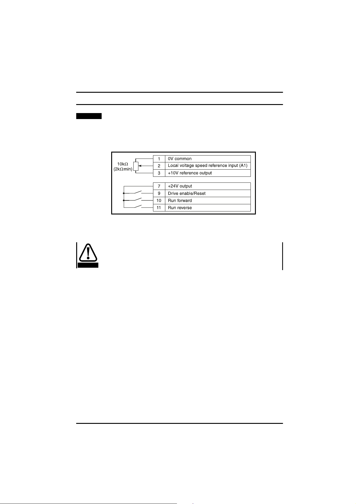
7 Getting Started - Bench Testing
NOTE
The following Getting Started procedures assume that the Drive is
in its default condition (as supplied) and that no parameters have
been changed.
7.1 Terminal control
7.1.1 Basic connections
1 Connect the Drive to the AC supply circuit and motor as described in
Chapter 5
Observe the safety precautions and ensure the correct fuses or
other circuit protection are fitted.
WARNING
2 Make the signal connections as shown in Figure 7.1
3 Perform the following checks:
• ACsupply and motor connections are correct.
• Motorinstallation and motor voltage connections (star/delta) are
• Motor shaft is not exposed.
• Terminals 9, 10 and 11 are NOT connectedto terminal 7. This
• Speed potentiometer is set at minimum.
4 Apply AC power to the Drive.
5UsingtheMODE, UP and DOWN keys, enter the Drive’s motormap
parameters, 06, 07, 08 & 09. Also parameter 02
parameter 39
motor poles
values should be taken from the motor’s rating plate.
Terminals
correct.
ensures that the motor will not start when AC power is applied
to the Drive.
should be set to the correct value if required.These
Figure 7.1 Basic connections
.
Motor rated frequency
and parameter 40
Maximum speed
Number of
,
Commander SE User Guide
Issue Number 5 67
Page 72
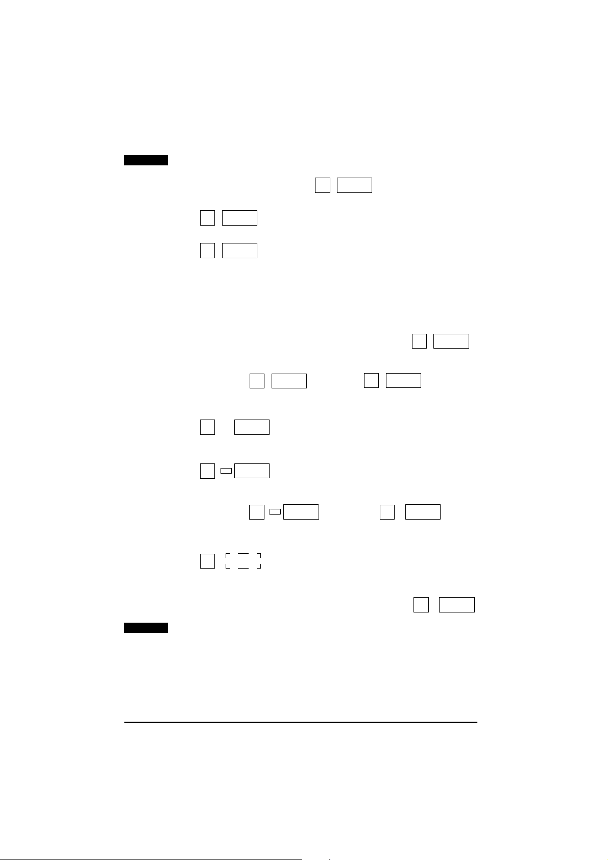
NOTE
If the previous parameters are not set correctly then the speed /
frequency value on the display may be incorrect.
6 The display should show
ih
0.0
7ClosetheENABLE contact. The display should show
rd
0.0
8ClosetheRUN FORWARD contact. The display should show
Fr
0.0
9 If this is the first time the Drive has been run, the Drive will perform a
non-rotating autotune to measure the stator resistance and voltage
offset.
Auto tunE
will flash in the right hand display during this
procedure. Once this has been carried out, the motor will run as
requested.
10 Advance the Speed potentiometer. The value in the right hand
display should increase accordingly, for example
Fr
25.8
11 Open the RUN FORWARD contact. The display should show a
reducing frequency since the Drive is decelerating, for
example and then
Fr
10.3
rd
0.0
Turn the speed potentiometerback to zero.
12 Close the RUN REVERSE contact. The display should show
Fr
0.0
13 Advance the Speed potentiometer. The value in the right hand
display should increase accordingly, for example
Fr
31.4
The sign LED is lit to show the Drive is running reverse.
14 Open the RUN REVERSE contact. The display should show, for
example and then
Fr
13.7
rd
0.0
Turn the potentiometer back to zero.
15 If the Drive trips during these tests the display will show, for example
tr
OU
The right hand display will flash with the trip code.
16 To RESET the trip, OPEN and then CLOSE the ENABLE contact or
NOTE
pressthe Stop/Resetkey. The display should show:
rd
Following a DRIVE TRIP and a RESET via the STOP/RESET key, the
0.0
RUN FORWARD or RUN REVERSE terminal will need to be OPENED
and CLOSED to allow the Drive to run.
Commander SE User Guide
68 Issue Number 5
Page 73
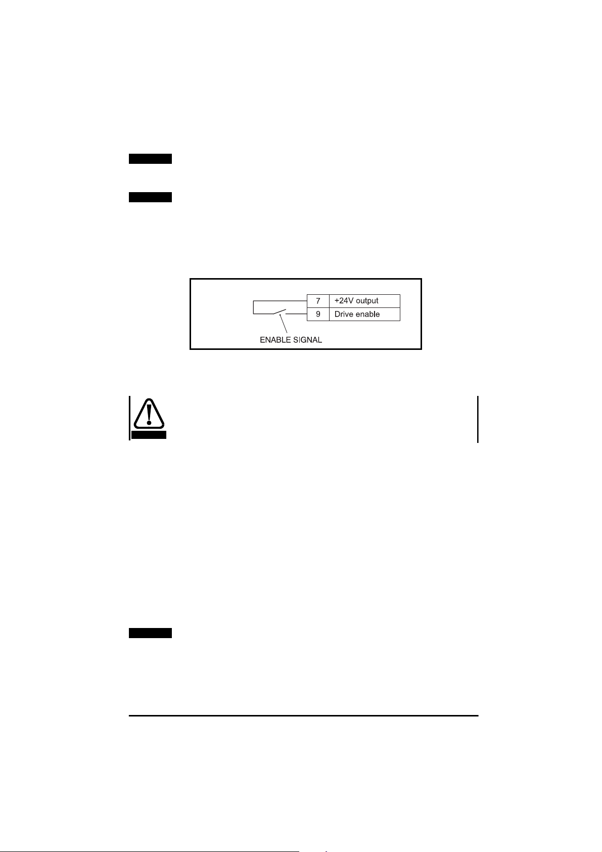
NOTE
Following a DRIVE TRIP and a RESET via the DRIVE ENABLE
terminal, if the RUN FORWARD or RUN REVERSE terminal is
already CLOSED, the Drive will run straight away.
NOTE
If this test has been carried out as a bench test and the Drive is to
be connected to a different motor with different characteristics etc.
in the application, then the motor map parameters should be set to
the correct values for the new motor and another autotune carried
out (see parameter 38 for details).
7.2 Keypad control
7.2.1 Basic connections
1 Connect the Drive to the AC supply circuit and motor as described in
Chapter 5,
Observe the safety precautions and ensure the correct fuses or
WARNING
other circuit protection are fitted.
Figure 7.2 Keypad basic connections
Terminals
2 Make the signal connections as shown in Figure 7.2.
3 Perform the following checks:
• ACsupply and motor connections are correct.
• Motorinstallation and motor voltage connections (star/delta) are
correct.
• Motor shaft is not exposed.
4 Apply AC power to the Drive.
5UsingtheMODE, UP and DOWN keys, enter the Drives’ motor map
parameters, 06, 07, 08 & 09. Also parameter 02
parameter 39
motor poles
Motor rated frequency
should be set to the correct value if required.These
and parameter 40
Maximum Speed
Number of
,
values should be taken from the motors rating plate.
NOTE
If the above parameters are not set correctly then the speed /
frequency value on the display may be incorrect.
Commander SE User Guide
Issue Number 5 69
Page 74
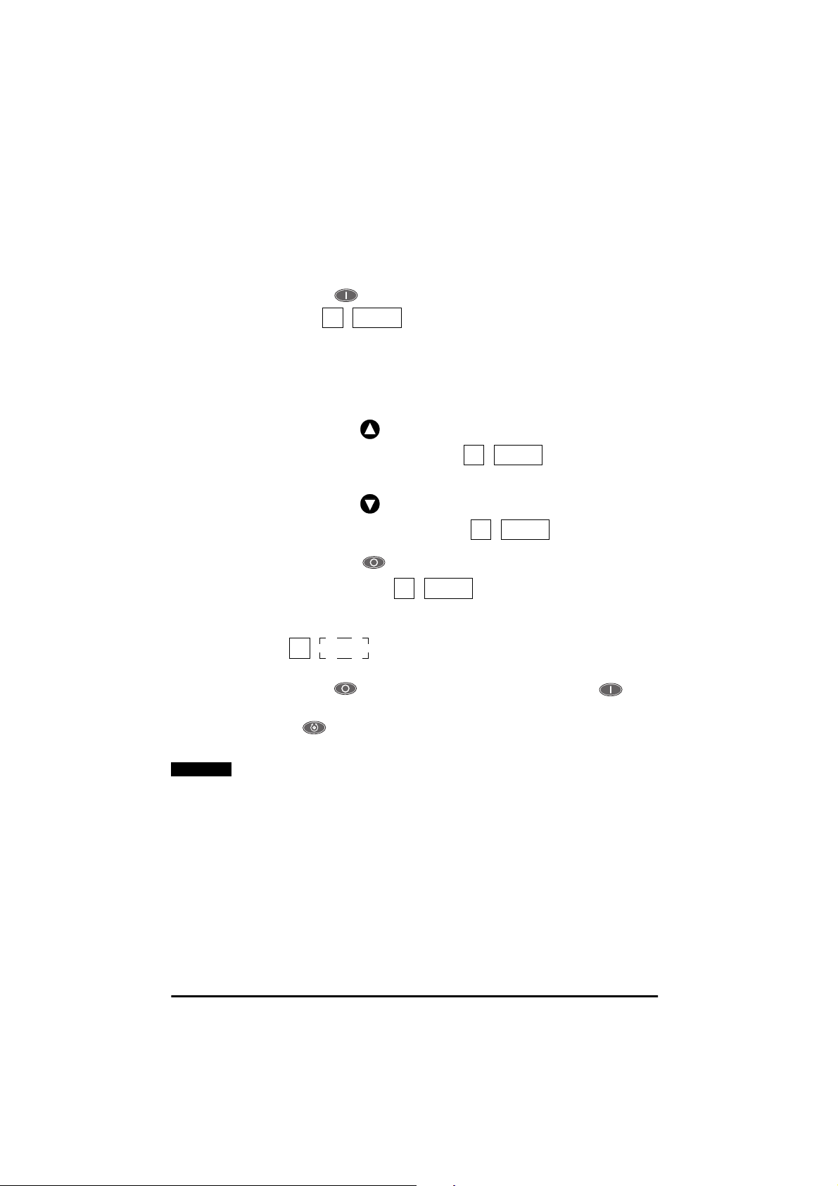
7.2.2 Setting keypad control
Set parameter 05 to PAd.
7.2.3 Using keypad control
1 Press the RUN key to START the Drive. The display s hould
show:
2 If this is the first time the Drive has been run, the Drive will perform a
non-rotating autotune to measure the stator resistance and voltage
offset.
procedure. Once this has been carried out, the motor will run as
requested.
• Press the key to increase the motor speed. The display
• Press the key to decrease the Drives speed. The display
• Pressthe STOP key to STOP the Drive. The display
Fr
Auto tunE
should show, for example:
should show, for example:
should show:
will flash in the right hand display during this
0.0
rd
0.0
Fr
Fr
10.0
5.0
3 If the Drive trips during these tests the display will show, for example
OU
NOTE
tr
The right hand display will flash with the trip code
4 Press the RESET button to reset the trip. Press the RUN
buttontoruntheDrive.
5The FORWARD/REVERSE button can be enabled by setting
parameter 26 = On.
If this test has been carried out as a bench test and the Drive is to
be connected to a different motor with different characteristicsetc.
in the application, then the motor map parameters should be set to
the correct values for the new motor and another autotune carried
out (see parameter 38 for details).
Commander SE User Guide
70 Issue Number 5
Page 75

8 Diagnostics and Protective Features
Do not attempt to carry out internal repairs. Return a faulty Drive
WARNING
8.1 Trip codes
Trip
Code
UU 1 DC link under voltage Low AC supply voltage
OU 2 DC link over voltage Excessive inertia in the machine during
OI.AC** 3 AC instantaneous over current
OI.br** 4 Overcurrent on braking IGBT Excessive current in braking resistor
Et 6 External trip External trip terminal opened (when
O.SP 7 Over speed Excessive motor speed (typically caused
tunE 18 Auto-tune failure Motor loaded or no motor connected
It.br 19 Ixt on braking resistor Excessive braking resistor energy
It.AC 20 Motor overload on current x time Too muc h mechanical load
Oht1 21 Overheat Overheatthermal model
Oht2 22 Overheat (heatsink thermistor) Temperature exceeds 95°C (203°F)
to the supplier for repair.
Thefollowingprotectivefeaturesare incorporated withintheCommander
SEDrive. They are placedin order of Trip number whichis thefigure that
is read back through the serial comms.
When a trip c ondition occurs, the left hand display will show the legend
whilst the right hand display flashes one of the trip codes given in
tr
Table 8.1.
Table 8.1 Trip Codes
Trip
Number
trip
Condition Possible Cause
Low DC link voltage when supplied by
external DC power supply
deceleration
Deceleration rate set too fast for inertia of
machine
Insufficient ramp times
Phase to phase or phase to earth shortcircuit at the Drive output
Drive requires autotuning to motor (see
parameter 38)
Braking resistor value too small
(Does not apply to Size 1 units)
programmed)
by the mechanical load driving the motor)
(Does not apply to Size 1 units)
Commander SE User Guide
Issue Number 5 71
Page 76

Trip
Code
th 2 4 Over temperature (Motor
O.Ld1* 26 +24V or d igital output overload Excessive load or short circuit on +24V
cL 28 Current loop loss on terminal 5 Input current less than 3mA when 4-20 or
SCL 30 User serial communications
EEF 31 Failure of internal EEPROM Possible loss of parameter values
PH 3 2 Phase loss One of the input phases has become
rS 33 Stator resistance measurement
trxx 40-99 User trips where xx is the user
F.bus 180 Field bus disconnection whilst in
C.Err 182 Quickey memory corrupt Bad connection or memory corrupt
C.dat 183 Quickey with no data New / empty Quickey being read
C.Acc 185 Quickey write fail Bad connection or faulty Quickey
C.rtg 186 Quickey voltage rating change Already programmed Quickey read by
O.Ld2 188 +28V serial communications
O.cL 189 Current loop input overload Input current exceeded 25mA
Trip
Number
Condition Possible Cause
thermistor)
watchdog failure
failure
trip number
use
power supply overload
Motor runs unstable Motor or motor connections changed.
Excessive motor temperature
output
20-4 modes used
Failure of serial communications between
Drive and master
Corruption due to severe electrical noise
Set default parameters (see parameter
29)
disconnected from the Drive. (This
applies to 200V/400V three phase units
only,not dual rated units).
Motor cable disconnected during
measurement
Motor too small for Drive
See parameter 38 for more details
Drive of different rating
Overload of more than 110 mA or short
circuit on +28V serial communications
power supply
Check motor connections and
re-autotune Drive to motor (see
parameter 38)
* The Enable/Reset terminal will not reset an O.Ld1 trip. Use the Stop/
Reset key.
** These trips cannot be reset for 10 seconds.
If any of the above trips persist, please consult a Drive Centre.
OU - Overvoltage trip levels:
200V units - 420VDC
400V units - 830VDC
Commander SE User Guide
72 Issue Number 5
Page 77

Braking levels:
200V units - 390VDC
400V units - 780VDC
UU - Undervoltage trip levels:
200V units - 180VDC
400V units - 400VDC
Reset from UU - Under voltage trip:
200V units - 235VDC
400V units - 460VDC
NOTE
These are the absolute minimum DC voltages that the Drive can be
supplied by.
8.2 Alarm warnings
Therearethree ALARM codeswhichflashin the righthand display,along
with the standard display, to warn the user that if no action is taken, the
Drive will trip. The codes are shown in Table 8.2.
For example:
Table 8.2 Alarm Warnings
Display Condition Cause Solution
OVL l x t overload Motor current greater
hot Heatsink/IGBT
junction
temperature high
*br.rS
Braking resistor
overload
* Does not apply to Size 1 units.
Fr
50.0
than programmed rated
motor current
Drive running outside
specified ambient
temperature/motor
current rating curves
Braking resistor thermal
model exceeded
hot
50.0
Reduce motor current
(load)
Reduce ambient
temperature or reduce
motor current (load)
See
Commander SE
Advanced User Guide
8.3 HF-Hardware fault trip codes
HF trips are internal hardware faults within the Drive. Powering the Drive
down and re-applying power could clear the fault.
NOTE
For full list of hardware fault trip codes, refer to the
Advanced U ser Guide
.
If a HF trip occurs, the Drive Healthy relay will open to indicate this.
Commander SE
The serial communications will not function during a HF trip.
Commander SE User Guide
Issue Number 5 73
Page 78

9 Parameter List
Par Description Default Setting 1 Setting 2
EUR USA
01 Min. speed (Hz) 0.0
02 Max. speed (Hz) 50.0 60.0
03 Accel. rate (s/100Hz) 5.0
04 Decel. rate (s/100Hz) 10.0
05 Ref. select A1.A2 PAd
06 Motor rated current (A) Drive rating
07 Motor rated speed (rpm) 1500 1800
08 Motor rated voltage (V) 230 / 400 230/ 460
09 Motor power factor 0.85
10 Parameter access L1 L1
11 Preset 1 (Hz) 0.0
12 Preset 2 (Hz) 0.0
13 Preset 3 (Hz) 0.0
14 Preset 4 (Hz) 0.0
15 Jog. speed (Hz) 1.5
16 Current mode (mA) 4-.20
17 Enable negative preset speeds OFF
18 Last trip -19 Trip before parameter 18 -20 Trip before parameter 19 -21 Trip before parameter 20 -22 Load display units Ld
23 Speed display units Fr
24 Customer scaling 1.00
25 Security setup 0
26 Fwd/rev key enable OFF
27 Power up key. ref 0
28 Parameter cloning no
29 Load defaults no
30 Ramp mode 1
31 Stoppingmode 1
32 Variabletorque select OFF
33 Spinning motor select 0
34 Positive logic select On
35 Start/Stop logic select 0
36 Analog output select Fr
37 Switching frequency (kHz) 6
38 Auto tune 0
39 Rated frequency (Hz) 50.0 60.0
40 No. of poles Auto
41 Serial mode AnSI
42 Baud rate 4.8
43 Serial address 1.1
44 Software version -*45 Fieldbus node address 0
*46 Fieldbus baudrate 0
*47 Fieldbus diagnostics 0
*Will only appear when parameter 41 is set to Fbus
Commander SE User Guide
74 Issue Number 5
Page 79

10 Advanced Functions
The Commander SE can also offer many advanced functions. A full
explanation of these can be found inthe
.
Guide
10.1 Speed control
• Adjustable precision speed reference
• 3 adjustable skip frequencieswith 3 adjustable skip bands
• 8 adjustable preset speeds
10.2 Ramps
• 8 preset acceleration ramps
• 8 preset deceleration ramps
• Separate acceleration and deceleration ramps for preset speeds
• Separate acceleration and deceleration ramps for jogging
• Adjustable S-ramp
10.3 Torque control
10.4 Stopping
• Adjustable DC injection braking current level and time
10.5 Programmable I/O
• Fully programmable analog and digital I/O for alternative functions
10.6 Motor protection
• Current limiting (short-term overload)
• Motor thermistor protection (long-term overload)
• Protection trips with trip log
10.7 Monitoring
• Programmable Drive status logic
• Status and diagnostic information
•kWhmeter
•Runtimelog
• Adjustable speed sensing levels
• Running costs
CommanderSE AdvancedUser
10.8 Auxiliary functions
• Auto reset
• PID controller
• Un-dedicated programmable logic
• Un-dedicated programmable threshold comparator
• Motorised potentiometer
10.9 Second motor selection
• With second motor map parameters
Commander SE User Guide
Issue Number 5 75
Page 80

11 UL Listing Information
11.1 Common UL information
Conformity
The Drive conforms to UL listing requirements only when the following
are observed:
• Class 1 60/75°C (140/167°F) copper wire only is used in the
installation.
• The ambient temperature does not exceed 40°C(104°F) when the
Drive is operating.
• The terminal tightening torques specified in Chapter 5
used.
• The Drive is installedinto a separate electrical enclosure. The Drive
has a UL ‘Open-type’ enclosure rating.
AC Supply Specification
The Drive is suitable for use in a circuit capable of delivering not more
than 5000RMS symmetrical Amperes at 264VAC RMS maximum(200V
models) or 528VAC RMS maximum (400V models).
Motor Overload Protection
The Drive provides motor overload protection. The overload protection
level is 150% of full-load current. It is necessary for the motor rated
current to be entered into parameter 6 for the protection to operate
correctly. The protection level may be adjusted below 150% if required.
Refer to the
information.
Overspeed Protection
The Drive does not incorporate overspeed protection.
Commander SE Advanced User Guide
Terminals
for further
are
11.2 Power dependant UL information
11.2.1 Commander SE Size 1
Conformity
The Drive conforms to UL listing requirementsonly when the following is
observed:
• UL listed class CC fast acting fuses e.g. Bussman Limitron KTK
series, Gould Amp-Trap ATM series or equivalent are used in the AC
supply.
NEMA Enclosure rating
The Drive has a NEMA type 1 enclosure rating. NEMA type 1 is an
enclosureconstructed for indoor use to provide a degree of protection to
personnel against incidental contact with the enclosed equipment and to
provide a degree of protection against falling dirt.
Commander SE User Guide
76 Issue Number 5
Page 81

11.2.2 Commander SE Size 2
Conformity
The Drive conforms to UL listing requirements only when the following
are observed:
• UL listed class CC fast acting fuses e.g. Bussman Limitron KTK
series,Gould Amp-Trap ATM series or equivalent are used in the AC
supply for 200 and 400VAC input models with the following
exceptions:
• The SE2D200220 when operated from a single phase supply must
use a 35A UL listed class J fast acting fuse e.g.Littelfuse PowerGard
JLS35.
• With reference to Table 3.7, the SE23200400may use 30A UL listed
class CC fast acting fuses.
11.2.3 Commander SE Size 3
Conformity
The Drive conforms to UL listing requirementsonly when the following is
observed:
• UL listed class CC fast acting fuses e.g. Bussman Limitron KTK
series,Gould Amp-Trap ATM series or equivalent are used in the AC
supply.
Commander SE User Guide
Issue Number 5 77
 Loading...