

Page 1
Control User Guide
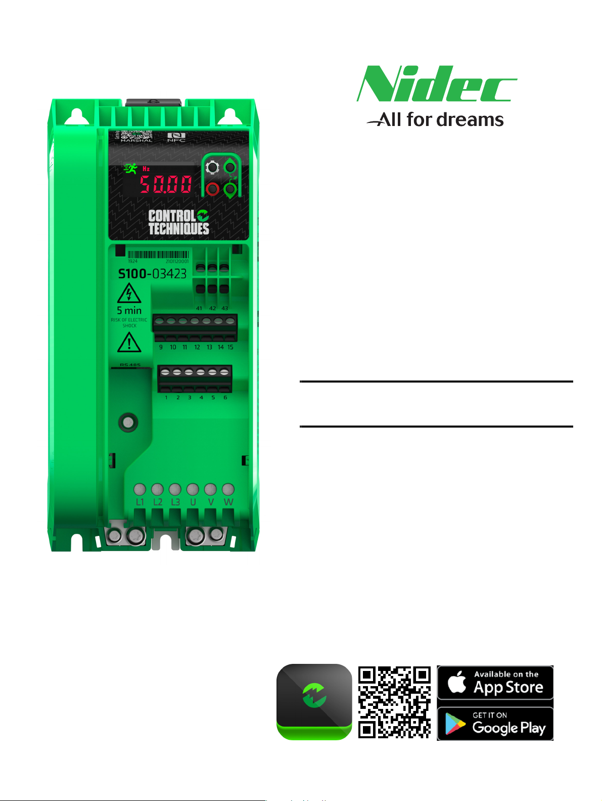
Commander S100
Variable Speed AC drive for induction
motors
Part Number: 0478-0650-00
Issue: 0
MARSHAL
Page 2
Original Instructions
For the purposes of compliance with the EU Machinery Directive 2006/42/EC, the English version of this User Guide is the Original Instructions.
User Guides in other languages are Translations of the Original Instructions.
The information contained in this User Guide is believed to be correct at the time of printing and does not form part of any contract. The manufacturer
reserves the right to change the specification of the product and its performance, and the contents of the User Guide, without notice.
Documentation & User Software Tools
User Guides, datasheets and software are available to download from: http://www.drive-setup.com
Marshal (Mobile App) is available to download from the Google Play store and the App Store.
Warranty and Liability
In no event and under no circumstances shall the manufacturer be liable for damages and failures due to misuse, abuse, improper installation, or
abnormal conditions of temperature, dust, or corrosion, or failures due to operation outside the published ratings. The manufacturer is not liable for
consequential and incidental damages. Contact the supplier of the drive for full details of the warranty terms.
Environmental policy
Control Techniques operates an Environmental Management System (EMS) that conforms to the International Standard ISO 14001. Further
information on our Environmental Policy can be found at: http://www.drive-setup.com/environment
Restriction of Hazardous Substances (RoHS)
The products covered by this User Guide comply with European and International regulations on the Restriction of Hazardous Substances including
EU directive 2011/65/EU and the Chinese Administrative Measures for Restriction of Hazardous Substances in Electrical and Electronic Products.
Disposal and Recycling (WEEE)
When electronic products reach the end of their useful life, they must not be disposed of along with domestic waste but should be recycled
by a specialist recycler of electronic equipment. Control Techniques products are designed to be easily dismantled into their major
component parts for efficient recycling. The majority of materials used in the product are suitable for recycling.
Product packaging is of good quality and can be re-used. Smaller products are packaged in strong cardboard cartons which have a high
recycled fibre content. Cartons can be re-used and recycled. Polythene, used in protective film and bags for wrapping the product, can
be recycled. When preparing to recycle or dispose of any product or packaging, please observe local legislation and best practice..
REACH legislation
EC Regulation 1907/2006 on the Registration, Evaluation, Authorisation and restriction of Chemicals (REACH) requires the supplier of an article to
inform the recipient if it contains more than a specified proportion of any substance which is considered by the European Chemicals Agency (ECHA)
to be a Substance of Very High Concern (SVHC) and is therefore listed by them as a candidate for compulsory authorisation.
Further information on our compliance with REACH can be found at: http://www.drive-setup.com/reach
Registered Office
Nidec Control Techniques Ltd
The Gro
Newtown
Powys
SY16 3BE
UK
Registered in England and Wales. Company Reg. No. 01236886.
Copyright
The contents of this publication are believed to be correct at the time of printing. In the interests of a commitment to a policy of continuous development
and improvement, the manufacturer reserves the right to change the specification of the product or its performance, or the contents of the User Guide,
without notice.
All rights reserved. No parts of this User Guide may be reproduced or transmitted in any form or by any means, electrical or mechanical including
photocopying, recording or by an information storage or retrieval system, without permission in writing from the publisher.
Copyright © February 2021 Nidec Control Techniques Ltd
Page 3

Contents
1 Safety information .................................4
1.1 Important Safety Information .................................4
1.2 Responsibility ........................................................4
1.3 Compliance with regulations .................................4
1.4 Electrical hazards ..................................................4
1.5 Mechanical hazards ..............................................5
1.6 Access to equipment .............................................5
1.7 Environmental limits ..............................................5
1.8 Hazardous environments ......................................5
1.9 Motor .....................................................................5
1.10 Adjusting parameters ............................................5
1.11 Electromagnetic compatibility (EMC) ....................5
1.12 Repairs ..................................................................5
1.13 Maintenance .........................................................5
2 Electrical installation ............................6
2.1 Control connections ..............................................6
3 Drive Parameters ...................................9
3.1 Parameter Groups ................................................9
3.2 Menu 0 - Quick Start ...........................................10
3.3 Full Parameter List ..............................................10
3.4 Menu 1 - Status & Monitoring .............................11
3.5 Menu 2 - Reference & Ramps ...........................12
3.6 Menu 3 – Motor Setup ........................................13
3.7 Menu 4 - General ................................................13
3.8 Menu 5 - PID Controller ......................................14
3.9 Menu 6 - IO Configuration ...................................15
3.10 Parameter Descriptions ......................................16
Commander S100 User Guide 3
Page 4
Safety information Electrical installation Drive Parameters
WARNING
CAUTION
NOTE
1 Safety information
1.1 Important Safety Information
Specific warnings are given at the relevant places in this User Guide as
follows:
A Warning contains information which is essential for
avoiding a safety hazard.
A Caution contains information which is necessary for
avoiding a risk of damage to the product or other equipment.
A Note contains information which helps to ensure correct operation of
the product.
1.1.1 Hazards
This User Guide applies to the Commander S100 and auxiliary
equipment. In all cases the hazards associated with powerful electrical
drives are present, and all safety information relating to drives and
associated equipment must be observed.
1.1.2 Competence of Designers and Installers
Drives and controllers are intended as components for professional
incorporation into complete systems. If installed incorrectly they may
present a safety hazard. The drive uses high voltages and currents,
carries a high level of stored electrical energy, and is used to control
equipment which can cause injury. Close attention is required to the
electrical installation and the system design to avoid hazards either in
normal operation or in the event of equipment malfunction. System
design, installation, commissioning and maintenance must be carried
out by personnel who have the necessary training and competence.
They must read all of the safety information and instructions in this User
Guide carefully
1.2 Responsibility
It is the responsibility of the installer to ensure that the equipment is
installed correctly with regard to all instructions given in this User Guide.
They must give due consideration to the safety of the complete system,
so as to avoid the risk of injury both in normal operation and in the event
of a fault or of reasonably foreseeable misuse.
The manufacturer accepts no liability for any consequences resulting
from inappropriate, negligent or incorrect installation of the equipment.
1.3 Compliance with regulations
The installer is responsible for complying with all relevant regulations,
such as national wiring regulations, accident prevention regulations and
electromagnetic compatibility (EMC) regulations. Particular attention
must be given to the cross-sectional areas of conductors, the selection
of fuses or other protection, and protective ground (earth) connections.
This guide contains instructions for achieving compliance with specific
EMC standards.
All machinery to be supplied within the European Union in which this
product is used must comply with the following directives:
2006/42/EC Safety of machinery.
2014/30/EU: Electromagnetic Compatibility.
1.4 Electrical hazards
The voltages used in the drive can cause severe electrical shock and/or
burns, and could be lethal. Extreme care is necessary at all times when
working with or adjacent to the drive. Hazardous voltage may be present
in any of the following locations:
• AC and DC supply cables and connections
• Output cables and connections
• Control terminals and cables
• Many internal parts of the drive, and external option units
The drive must be installed in accordance with the instructions given in
this User Guide. Failure to observe the instructions could result in a fire
hazard
1.4.1 Isolating the Drive
The drive contains capacitors that remain charged to a potentially lethal
voltage after the AC supply has been disconnected. If the drive has been
energized, the AC supply must be isolated by an approved electrical
isolation at least five minutes before work may continue. Ensure the
motor is not able to be driven by another part of the system as this could
produce a regenerating current which could cause unsafe voltages on
the drive terminals.
1.4.2 Stored Charge
Normally, the capacitors are discharged by an internal resistor. Under
certain, unusual fault conditions, it is possible that the capacitors may fail
to discharge or be prevented from being discharged by a voltage applied
to the output terminals. If the drive has failed in a manner that causes the
display to go blank immediately, it is possible the capacitors will not be
discharged. In this case, contact the supplier of the drive.
1.4.3 Products Connected by Plug and Socket
A special hazard may exist where the drive is incorporated into a product
which is connected to the supply by a plug and socket. When unplugged,
the pins of the plug may be connected to the drive input, which is
separated from the charge stored in the capacitor only by semiconductor
devices. To avoid any possibility of electric shock from the pins, if they
are accessible, a means must be provided for automatically isolating the
plug from the drive - e.g. a latching contactor.
1.4.4 Grounding / Earthing
The drive must be grounded by a conductor sufficient to carry the
prospective fault current in the event of a fault and in a zone of
equipotential bonding. The ground loop impedance must conform to the
requirements of local safety regulations. The ground connections must
be inspected and tested at appropriate intervals.
Ground conductor size:- Either a single copper 10 mm² conductor or two
conductors of the same cross-sectional area and material as the input
conductors so long as the size of each conductor is 2.5 mm2. For
location of ground connections refer to Figure 1-1 in the Step by Step
guide.
Each ground connection requires an individual terminal or connection
point. If using two conductors for the input and the cable management
bracket, the motor ground should be connected to the grounding
bracket.
1.4.5 Fuses and Circuit Breakers
The AC supply to the drive must be installed with suitable protection
against overload. Failure to observe this requirement will cause risk of
fire. Integral solid-state short circuit protection does not provide branch
circuit protection. Branch circuit protection must be provided in
accordance with the National Electrical Code (NEC), The Canadian
Electrical Code, and any additional local codes. Opening of the branchcircuit protective device may be an indication that a fault has been
interrupted. To reduce the risk of fire or electric shock, the equipment
should be examined and replaced if damaged. If burnout of the current
element of an overload relay occurs, the complete overload relay must
be replaced. If opting to use a residual current device, only type B should
be used with the drive.
4 Commander S100 User Guide
I
Page 5

Safety information Electrical installation Drive Parameters
1.4.6 Over-Current Protection
The devices incorporate solid state overload protection for the motor
load. The protection levels are expressed as a percentage of full-load
current. For the motor protection to work properly, Motor Rated Current
(P0.06) must be set correctly. The protection level may be adjusted
below 150 % if required using Motor Output Current Limit (P3.17). All
models are provided with thermal memory retention.
1.4.7 Isolation of control circuits
Unless otherwise indicated, control terminals and the EIA-485
Communications port are isolated from the power circuits in the drive by
double/reinforced insulation. The installer must ensure that the external
control circuits do not compromise this insulation barrier. If the control
circuits are to be connected to circuits classified as Safety Extra Low
Voltage (SELV) - for example, to a personal computer - an additional
basic barrier must be included in order to maintain the SELV
classification.
1.4.8 Terminal Connections and Torque Settings
Loose power connections are a fire risk. Always ensure that terminals
are tightened to the specified torques. Refer to the tables in chapter 4
Electrical Installation.
1.5 Mechanical hazards
Careful consideration must be given to the functions of the drive or
controller which might result in a hazard, either through their intended
behaviour or through incorrect operation due to a fault. In any application
where a malfunction of the drive or its control system could lead to or
allow damage, loss or injury, a risk analysis must be carried out, and
where necessary, further measures taken to reduce the risk - for
example, an over-speed protection device in case of failure of the speed
control, or a fail-safe mechanical brake in case of loss of motor braking.
None of the drive functions must be used to ensure safety of
personnel. i.e. they must not be used for safety-related functions.
The system designer is responsible for ensuring that the complete
system is safe and designed correctly according to the relevant safety
standards.
The design of safety-related control systems must only be done by
personnel with the required training and experience. The system must
be subject to a risk assessment to confirm that the residual risk of an
unsafe event is at an acceptable level for the application.
The values of the motor parameters set in the drive affect the protection
of the motor. The default values in the drive must not be relied upon. It is
essential that the correct value is entered in the Motor Rated Current
(P3.01).
1.9.1 Motor Sizing
The motor rated current should not exceed the maximum continuous
output current of the drive. The maximum output voltage of the drive is
not able to exceed the input voltage and the rated voltage of the motor
should therefore be less than this value. Typical overloads are 150% for
60 s (from cold) or 150% for 8 s (from hot). The drive will initiate an error
if the drive output current exceeds the over-current threshold which
could occur in the event of a short circuit of the motor output cables. The
over-current threshold is the maximum current the drive can measure.
1.10 Adjusting parameters
It is essential that changes to the drive parameters are given careful
consideration. Depending on the application, a change could result in
unexpected motor behaviour. Appropriate precautions must be taken
against inadvertent changes or tampering. Some specific parameters
which require particular care are: parameters in IO Configuration (Menu
6) (the drive may start unexpectedly if the logic or functions are
changed); Restore Factory Defaults (P4.01) (depending on the
application this may cause unpredictable or hazardous operation);
parameters in Motor Setup (Menu 3) (overheating and possible fire risk
could result from seriously incorrect settings).
1.11 Electromagnetic compatibility (EMC)
Installation instructions for a range of EMC environments are provided in
section 4.5 Electromagnetic compatibility (EMC). If the installation is
poorly designed or other equipment does not comply with suitable
standards for EMC, the product might cause or suffer from disturbance
due to electromagnetic interaction with other equipment. It is the
responsibility of the installer to ensure that the equipment or system into
which the product is incorporated complies with the relevant EMC
legislation in the place of use.
1.12 Repairs
Users must not attempt to repair a drive if it is faulty. It must be returned
to the supplier of the drive. Users must not make any attempt at
removing drive plastics to inspect the internal parts of the drive.
1.6 Access to equipment
Access must be restricted to authorized personnel only. Safety
regulations which apply at the place of use must be complied with.
1.7 Environmental limits
Instructions in this guide regarding transport, storage, installation and
use of the equipment must be complied with, including the specified
environmental limits. This includes temperature, humidity,
contamination, shock and vibration. Drives must not be subjected to
excessive physical force.
1.13 Maintenance
Regular inspections and maintenance should be carried out to ensure
drive's reliability is maximized. See detailed information in the in section
3.11 Routine Maintenance.
1.8 Hazardous environments
The equipment must not be installed in a hazardous environment
(i.e. a potentially explosive environment).
1.9 Motor
The safety of the motor under variable speed conditions must be
ensured.
To avoid the risk of physical injury, do not exceed the maximum specified
speed of the motor.
Low speeds may cause the motor to overheat because the cooling fan
becomes less effective, causing a fire hazard. If possible, the motor
should be installed with a protection thermistor. If necessary, an electric
forced vent fan should be used.
Commander S100 User Guide 5
Page 6
Safety information Electrical installation Drive Parameters
CAUTION
CAUTION
NOTE
2 Electrical installation
2.1 Control connections
2.1.1 General Warnings
If any of the digital inputs are connected in parallel with an inductive load (i.e. contactor or motor brake) then suitable suppression (i.e.
diode or varistor) should be used on the coil of the load. If no suppression is used, then over voltage spikes can cause damage to the
digital inputs and outputs on the drive.
The control 0 V terminals are connected to earth but must not be used for protective purposes.
N
Any signal cables which are carried inside the motor cable (i.e. motor thermistor, motor brake) will pick up large pulse currents via the cable
capacitance. The shield of these signal cables must be connected to ground close to the point of exit of the motor cable, to avoid this noise current
spreading through the control system.
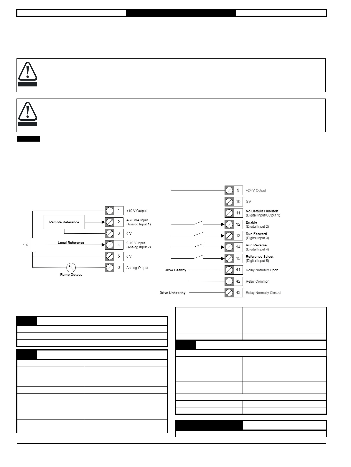
2.1.2 Control Terminal Connections
The default connections are suitable for basic motor speed control using analog inputs to define a frequency reference.
Figure 2-1 Default Control Terminal Connections
2.1.3 Control Terminal Specification
Control and relay terminals maximum cable size is 1.5 mm
2
T1 +10 V User Output
Supply for external analog devices
Nominal voltage 10.2 V
Voltage tolerance ±3 %
T2 Analog Input 1
Unipolar single-ended analog voltage or unipolar current input
Default function Remote Frequency Reference
Default Type 4 to 20 mA
Type Select Parameter T2 Analog Input 1 Type (P6.01)
As a Voltage Input (Default)
Full scale voltage range 0 V to +10 V ±3 %
Maximum offset ±30 mV
Absolute maximum voltage
range
Input resistance 100k Ω
As a Current Input
-18 V to +30 V relative to 0V
Current ranges 0 to 20 mA ±5 %, 4 to 20 mA ±5 %
Maximum offset 250 µA
Absolute maximum voltage
(reverse bias)
Absolute maximum current 25 mA
-18 V to +30 V relative to 0V
T2 Analog Input 1 (Continued)
As a Digital Input
Digital Function Select
Parameter
Switching Threshold as a
Voltage Input
Switching Threshold as a
Current Input
Common to all modes
Resolution 11 bits
Sample rate 4 ms
T2 Analog Input 1 Digital Function Select
(P6.14)
70 to 80 % *
45 to 55 %
1
T3,T5, T10 0 V Common
Unipolar single-ended analog voltage or unipolar current input
6 Commander S100 User Guide
Page 7
Safety information Electrical installation Drive Parameters
T4 Analog Input 2
Unipolar single-ended analog voltage or unipolar current input
Default function Ramp Output
Default Type 0 to 10 V
Type Select Parameter T4 Analog Input 2 Type (P6.02)
As a Voltage Input (Default)
Full scale voltage range 0 V to +10 V ±3 %
Maximum offset ±30 mV
Absolute maximum voltage
range
Input resistance 100k Ω
-18 V to +30 V relative to 0V
As a Current Input
Current ranges 0 to 20 mA ±5 %, 4 to 20 mA ±5 %
Maximum offset 250 µA
Absolute maximum voltage
(reverse bias)
Absolute maximum current 25 mA
-18 V to +30 V relative to 0V
As a Digital Input
Digital Function Select
Parameter
Switching Threshold as a
Voltage Input
Switching Threshold as a
Current Input
T4 Analog Input 2 Digital Function Select
(P6.15)
70 to 80 % *1
45 to 55 %
Common to all modes
Resolution 11 bits
Sample rate 4 ms
T6 Analog Output
Unipolar single-ended analog voltage or unipolar current output
Default function Ramp Output
Function Select Parameter T6 Analog Output Function Select
Default type 0 to 10 V
Type Select Parameter T6 Analog Output Type (P6.03)
Voltage Range 0 to 10 V
Current Range 0 to 20 mA or 4 to 20 mA
Maximum offset 15 mV
Load resistance ± 2k Ω
Protection Short circuit relative to 0 V
Resolution 0.1 %
Sample rate 4 ms
(P6.06)
T9 +24 V User Output
Supply for external analog devices
Voltage tolerance ±20 %
Maximum output current 100 mA (Shared with T11 Digital Output)
T11 Digital Input/Output 1
Multi-functional digital input or output
Default Function None
Function Select Parameters T11 Digital Input 1 Function (P6.16)
T11 Digital Output Function Select
(P6.09)
Default type Digital Input (Positive Logic)
Type Select Parameter
T11 Digital IO 1 Type (P6.04)
As a digital input (default)
Lower Threshold < 5 V
Upper Threshold > 11 V
T11 Digital Input/Output 1 (Continued)
Absolute maximum applied
voltage range -8 V to +30 V relative to 0V
Impedance 6.8 kΩ
Input threshold 10 V ±0.8 V (IEC 61131-2)
As a digital output
Maximum Source Current 50 mA (100 mA total limit on T9 and T11)
As a Frequency or PWM Output
Maximum Output
PWM Output
Resolution at Maximum Output
Resolution at Minimum Input
Common to all output types
Voltage Range 0 V to +24 V
Sample rate 4 ms
T12 Digital Input 2
T13 Digital Input 3
T14 Digital Input 4
Programmable Digital Inputs
T12 Default Function Enable
T13 Default Function Run Forward
T14 Default Function Run Reverse
Function Select Parameters
Default Logic Positive Logic
Lower Threshold < 5 V
Upper Threshold > 11 V
Absolute maximum applied
voltage range
Impedance 6.8 kΩ
Input threshold 10 V ±0.8 V (IEC 61131-2)
Voltage Range 0 V to +24 V
Sample rate 4 ms
T12 Digital Input 2 Function (P6.17)
T13 Digital Input 3 Function (P6.18)
T14 Digital Input 4 Function (P6.19)
-8 V to +30 V relative to 0V
T15 Digital Input 5
Programmable Digital Input or Frequency Input
T15 Default Function Enable
Function Select Parameter T15 Digital Input 5 Function (P6.20)
Default Logic Positive Logic
Lower Threshold < 5 V
Upper Threshold > 11 V
Absolute maximum applied
voltage range
Impedance 6.8 kΩ
Input threshold 10 V ±0.8 V (IEC 61131-2)
Voltage Range 0 V to +24 V
Sample rate 4 ms
-8 V to +30 V relative to 0V
As a Frequency Input
Maximum Frequency 100 kHz
Commander S100 User Guide 7
Page 8
Safety information Electrical installation Drive Parameters
T41 Relay Normally Open
T42 Relay Common
T43 Relay Normally Closed
Programmable Relay
Relay Default Function Drive Healthy
Function Select Parameter T12 Digital Input 2 Function (P6.17)
Default Logic Positive Logic
Lower Threshold
Upper Threshold > 11 V
Absolute maximum applied
voltage range
Impedance 6.8 kΩ
Input threshold 10 V ±0.8 V (IEC 61131-2)
Voltage Range 0 V to +24 V
Sample rate 4 ms
< 5 V
-8 V to +30 V relative to 0V
8 Commander S100 User Guide
Page 9

Safety information Electrical installation Drive Parameters
3 Drive Parameters
Parameters are variables within the drive that can be used to monitor output levels and drive statuses or to control the settings within the drive.
Parameters are divided into six menus based on their function which are:.
Menu 1 - Status & Monitoring (All read-only parameters)
Menu 2 - References and Ramps
Menu 3 - Motor Setup
Menu 4 - General
Menu 5 - PID Controller
Menu 6 - IO Configuration
There is also a quick start menu (Menu 0) that contains shortcuts to ten parameters used for basic drive setup. Because parameters in menu 0 are
shortcuts, changing the value of the parameter in menu 0 will also change the value in its original menu and vice versa.
3.1 Parameter Groups
The parameter groups listed below are parameters that behave in the same way.
Configuration Parameters
Automatically adjust settings of multiple parameters to quickly setup a certain function.
• Frequency Reference Configuration (P0.05)
• Enable/Run Configuration (P0.10)
Selector Parameters
Select an analog value to be used as an input.
• Reference Selector 1 (P2.21)
• Reference Selector 2 (P2.22)
• Reference Selector 3 (P2.23)
• Reference Selector 4 (P2.24)
• PID Reference Selector (P5.02)
• PID Feedback Selector (P5.03)
• PID Feedforward Selector (P5.04)
• PID Enable Selector (P5.10)
• Threshold Detector Selector (P5.11)
Input Function Select Parameters
Define the function of an input
• Keypad Run/Stop Key Function Select (P4.07)
• T2 Analog Input 1 Digital Function Select (P6.14)
• T4 Analog Input 2 Digital Function Select (P6.15)
• T11 Digital Input 1 Function Select (P6.16)
• T12 Digital Input 2 Function Select (P6.17)
• T13 Digital Input 3 Function Select (P6.18)
• T14 Digital Input 4 Function Select (P6.19)
• T15 Digital Input 5 Function Select (P6.20)
Output Function Select Parameters
Define the function of an output
• T6 Analog Output Function Select (P6.06)
• T11 Digital Output 1 Function Select (P6.09)
• T11 Frequency/PWM Output Function Select (P6.10)
Commander S100 User Guide 9
Page 10
Safety information Electrical installation Drive Parameters
WARNING
3.2 Menu 0 - Quick Start
For a description of a parameter in menu 0, refer to the alternative location of the parameter in the section 7.4 Parameter Descriptions.
Parameter
P0.01 Minimum Frequency Clamp 0.0 to 300.0 Hz (50 Hz: -50.0 Hz, 60 Hz: -60.0 Hz) P2.01
P0.02 Maximum Frequency Clamp 0.0 to 300.0 Hz (50 Hz: 50.0 Hz, 60 Hz: 60.0 Hz) P2.02
P0.03 Acceleration Rate 1 0.0 to 6000.0 s/Hz(max) (5.0 s/Hz(max)) P2.07
P0.04 Deceleration Rate 1 0.0 to 6000.0 s/Hz(max) (10.0 s/Hz(max)) P2.08
P0.05 Frequency Reference Configuration
P0.06 Motor Rated Current 0.00 to Drive Rated Current A (Rating Dependent) P3.01
P0.07 Motor Rated Speed 0 to 18000 rpm (50 Hz: 1500 rpm, 60 Hz: 1800 rpm) P3.02
P0.08 Motor Rated Voltage 0 to Drive Rated Voltage (Rating Dependent) P3.03
P0.09 Motor Rated Power Factor 0.00 to 1.00 (0.80) P3.04
P0.10 Run/Stop Configuration
Range (Default)
Custom (0), Local/Remote (1), Voltage/Preset Input (2), Current/Preset Input (3),
Presets (4), Keypad (5), Terminal Up/Down (6), Frequency Input (7),
PID Voltage Ref. (8), PID + Feed Forward (9)
Custom (0), Enable + Run Forward + Run Reverse (1), Run Forward + Run Reverse
(3 Wire) (2), Enable + Run + Reverse (3), Run + Reverse (4), Run + Jog (5), Run
Forward + Run Reverse (6), Run + Reverse (7), Keypad (8), Keypad With Enable (9),
Keypad Jog (10)
Alternative
Location
P2.03
P6.13
3.3 Full Parameter List
The list below contains all parameters within the drive and states the possible settings of the parameter with the default value outlined in bold where
applicable. For further description of the parameters refer to section 7.4 Parameter Descriptions or the help within the Marshal App that contain useful
graphics.
The lists in this table are for reference only and do not include sufficient information for adjusting these parameters. Incorrect
adjustment can affect the safety of the system and damage the drive and or external equipment. Before attempting to adjust any
of these parameters, refer to section 7.4 Parameter Descriptions.
10 Commander S100 USer Guide
Page 11
Safety information Electrical installation Drive Parameters
3.4 Menu 1 - Status & Monitoring
Parameter
P1.01 Output Frequency - Maximum Frequency Reference (P2.02) to Maximum Frequency Reference (P2.02) Hz
Output Voltage
P1.02
P1.03 Output Power Drive Rating Dependent kW
P1.04 Motor RPM ±18000 rpm
P1.05 Drive State
P1.06 Output Current - Drive Rated Current to Drive Rated Current A
P1.07 Torque Producing Current - Drive Rated Current to Drive Rated Current A
P1.08 Percentage Load - Motor Output Current Limit (Max) to Motor Output Current Limit (Max) %
P1.09 Alarm Indicators 00000000 to 11111111
P1.10 Drive Status Indicators 00000000 to 11111111
P1.11 Sequencer Input and Output Indicators 00000000 to 11111111
P1.12 Run & Direction Indicators 00000000 to 11111111
P1.13 Ramp Input ± Maximum Frequency Reference (P2.02) Hz
P1.14 Ramp Output ± Maximum Frequency Reference (P2.02) Hz
P1.15 T2 Analog Input 1 Percentage ±100.00 %
P1.16 T4 Analog Input 2 Percentage ±100.00 %
P1.17 T15 Frequency Input Percentage ±100.00 %
P1.18 Up/Down Percentage 0.00 to 100.00 %
P1.19 PID Percentage ±100.00 %
P1.20 PID Status Indicators 00000000 to 11111111
P1.21 PID Error ±100.00 %
P1.22 Motor Thermal Percentage 0 to 100 %
P1.23 Drive Thermal Percentage 0 to 100 %
P1.24 DC Bus Voltage
P1.25 Digital IO Indicators 00000000 to 11111111
P1.26 Parameter 1 Saved Value on Error -32768 to 32767
P1.27 Parameter 2 Saved Value on Error -32768 to 32767
P1.28 Parameter 3 Saved Value on Error -32768 to 32767
P1.29 Error 0to255
P1.30 Error History 1 0to255
P1.31 Error History 2 0to255
P1.32 Error History 3 0to255
P1.33 Drive Diagnostic 0to15
Inhibited (0), Ready (1), NA (2), NA (3), Running (4), Supply Loss (5), Deceleration (6), Injecting DC (7),
NA (8), Error (9), NA (10), NA (11), NA (12), NA (13), NA (14), Under Voltage (15)
(110 V, 200 V Drives = 240 V, 400 V Drives = 480 V)
(110 V, 200 V Drives = 415 V, 400 V Drives = 830 V)
0 to Maximum Output Voltage V
0 to Maximum D.C. Link Voltage V
Range
Commander S100 User Guide 11
Page 12
Safety information Electrical installation Drive Parameters
3.5 Menu 2 - Reference & Ramps
Parameter
P2.01 Minimum Frequency Limit 0.0 to 300.0 Hz 0.0 Hz
Maximum Frequency Limit
P2.02
P2.03 Frequency Reference Configuration
P2.04 Stopping Mode Selector
P2.05 S-Ramp Percentage 0.0 to 50.0 0.0
P2.06 Acceleration Rate 1 0.0 to 6000.0 s 5.0 s
P2.07 Deceleration Rate 1 0.0 to 6000.0 s 10.0 s
P2.08 Acceleration Rate 2 0.0 to 6000.0 s 5.0 s
P2.09 Deceleration Rate 2 0.0 to 6000.0 s 10.0 s
P2.10 Ramp Rate Selector 0 to 2 0
P2.11 Deceleration Ramp Type Fast (0), Standard Ramp (1), Standard Ramp + Motor (2) Standard Ramp (1)
P2.12 Standard Ramp Voltage 0 to DC Link Voltage (Max) V
P2.13 Jog Frequency ± Maximum Frequency Reference (P2.02) Hz 1.5 Hz
P2.14 Up/Down Percent Configuration
P2.15 Up/Down Percentage Time to Max 0 to 250 s 20 s
P2.16 Preset Frequency 1
P2.17 Preset Frequency 2 10.0 Hz
P2.18 Preset Frequency 3 25.0 Hz
P2.19 Preset Frequency 4 50.0 Hz
P2.20 Frequency Reference 1 to 4 Selector
P2.21 Frequency Reference 1 Selector
P2.22 Frequency Reference 2 Selector Analog 2 Percent (7)
P2.23 Frequency Reference 3 Selector None (0)
P2.24 Frequency Reference 4 Selector None (0)
P2.25 Skip Frequency
P2.26 Skip Frequency Band 0.0 to 25.0 Hz 0.0 Hz
Custom (0), Local/Remote (1), Voltage/Preset Input (2), Current/Preset Input (3),
Presets (4), Keypad (5), Terminal Up/Down (6), Frequency Input (7),
PID Voltage Ref. (8), PID + Feed Forward (9)
Coast (0), Ramp (1), Ramp & Brake (2), DC Brake, 0Hz detect (3),
Reset (0), Last (1), Preset 1 (2), Keypad and Reset (3), Keypad and Last (4),
± Maximum Frequency Reference (P2.02) Hz
Binary (0), Freq. Reference 1 (1), Freq. Reference 2 (2), Freq. Reference 3 (3),
None (0), Preset 1 (1), Preset 2 (2), Preset 3 (3), Preset 4 (4), Up/
Down Percent (5), Analog 1 Percent (6), Analog 2 Percent (7),
Frequency Input % (8), PID Percent (9)
- Maximum Frequency Reference (P2.02) to Maximum Frequency Reference
Range Default
0.0 to 300.0 Hz
Timed DC Brake (4)
Keypad and Preset 1 (5)
Freq. Reference 4 (4)
(P2.02) Hz
50Hz: 50.0 Hz
60Hz: 60.0 Hz
Local/Remote (1)
Ramp (1)
400V drive 50Hz: 375
V
400V drive: 750 V
400V drive 60Hz: 775
V
Reset (0)
5.0 Hz
Binary (0)
Analog 1 Percent (6)
0.0 Hz
12 Commander S100 USer Guide
Page 13
Safety information Electrical installation Drive Parameters
3.6 Menu 3 – Motor Setup
Parameter
P3.01 Motor Rated Current VM_RATED_CURRENT[MIN] to VM_RATED_CURRENT[MAX] A 6.80 A
Motor Rated Speed
P3.02
P3.03 Motor Rated Voltage 0 to Drive Rated Voltage V
P3.04 Motor Rated Power Factor 0.00 to 1.00 0.80
P3.05 Motor Control Mode Resistance Comp (0), Linear V to F (1), Square V to F (2) Linear V to F (1)
P3.06 Motor Starting Boost 0.0 to 25.0 5.0
P3.07 Motor Starting Boost End Voltage 0.0 to 100.0 50.0
P3.08 Motor Starting Boost End Frequency 0.0 to 100.0 50.0
P3.09 Perform Auto-tune Off (0) or On (1) Off (0)
P3.10 Energy Optimiser Off (0) or On (1) Off (0)
P3.11 Catch An Already Spinning Motor Disabled (0), Enabled (1), Forwards Only (2), Reverse Only (3) Disabled (0)
P3.12 PWM Switching Frequency Off (0) or On (1) Off (0)
P3.13 DC Braking Current Level 0.0 to 150.0 100.0
P3.14 DC Braking Time 0.0 to 100.0 s 1.0 s
P3.15 Motor Rated Frequency 0.0 to 300.0 Hz
P3.16 Number Of Motor Poles 0 to 8 0
P3.17 Motor Output Current Limit VM_MOTOR_CURRENT[MIN] to VM_MOTOR_CURRENT[MAX] 171.0
P3.18 Stator Resistance 0.00 to 199.99 Ω 2.00 Ω
P3.19 Motor Stability Optimiser Off (0) or On (1) Off (0)
P3.20 Reverse Motor Direction Off (0) or On (1) Off (0)
P3.21 Thermal Protection Action Disabled (0), Error with Save (1), Error (2), Limit with Save (3), Limit (4) Limit with Save (3)
P3.22 Low Frequency Thermal Protection Off (0) or On (1) On (1)
P3.23 Current Controller Gain 0 to 250 40
Range Default
0 to 18000 rpm
50 Hz: 1500 rpm
60 Hz: 1800 rpm
400 V drive 50
400 V drive: 400 V
400 V drive 60
50 Hz: 50.0 Hz
60 Hz: 60.0 Hz
Hz: 230 V
Hz: 460 V
3.7 Menu 4 - General
Parameter
P4.01 Restore Factory Defaults None (0), 50Hz (1), 60Hz (2) None (0)
P4.02 Security Pin 0 to 9999 0
P4.03 Serial Node Address 1 to 247 1
P4.04 Serial Mode 8.2NP (0), 8.1NP (1), 8.1EP (2), 8.1OP (3) 8.2NP (0)
P4.05 Serial Baud Rate
Minimum Serial Comms Transmit
P4.06
Delay
P4.07 Keypad Run and Stop Function Select 0 to 2 0
P4.08 Supply Loss Action Disable (0), Ramp Stop (1), Ride Through (2) Disable (0)
P4.09 Parameter 1 Save on Error Selector None (0), Output Frequency (1), Output Voltage (2), Output Power (3),
P4.10 Parameter 2 Save on Error Selector Motor RPM (4)
P4.11 Parameter 3 Save on Error Selector Drive State (5)
P4.12 Number of Auto Reset Attempts None (0), One (1), Two (2), Three (3), Four (4), Five (5), Continuous (6) None (0)
Hold Drive Healthy on Auto Reset Atte
P4.13
mpts
Drive Reset When Enable or Run Appli
P4.14
ed
P4.15 Motor Phase Loss Detection Off (0) or On (1) Off (0)
P4.16 User Error 0 to 255 0
P4.17 Drive Enable Off (0) or On (1) On (1)
P4.18 Binary Control Word 0000000000000000 to 1111111111111111 0000000000000000
P4.19 Save Parameters Off (0) or On (1) Off (0)
P4.20 Near Field Communication (NFC) Disabled (0), Read Only (1), Read & Write (2) Read & Write (2)
Disabled (0), 600 (1), 1200 (2), 2400 (3), 4800 (4), 9600 (5), 19200 (6), 38400 (7),
57600 (8), 76800 (9), 115200 (10)
Motor RPM (4), Drive State (5), Output Current (6), Torque Prod. Current (7),
Percentage Load (8), Alarm Indicators (9), Drive Status Indica. (10),
Sequ. In and Out (11), Run and Direction (12), Ramp Input (13),
Ramp Output (14), T2 Analog 1 Percent (15), T4 Analog 2 Percent (16),
T15 Freq. Input % (17), Up/Down Percentage (18), PID Percentage (19),
PID Status Indica. (20), PID Error (21), Motor Therm. Percent (22),
Drive Therm. Percent (23), DC Bus Voltage (24), Digital IO Indica. (25)
Range Default
115200 (10)
0to250ms 0ms
Output Power (3)
Off (0) or On (1) Off (0)
Off (0) or On (1) On (1)
Commander S100 User Guide 13
Page 14
Safety information Electrical installation Drive Parameters
3.8 Menu 5 - PID Controller
ParameterParameter RangeRange DDefaultefault
P5.01 PID Fixed Reference Set-Point 1 ±100.00 % 0.00 %
P5.02 PID Fixed Reference Set-Point 2 ±100.00 % 0.00 %
None (0), Analog 1 Percent (1), Analog 2 Percent (2),
P5.03 PID Reference Selector
P5.04 PID Feedback Selector
P5.05 PID Feed Forward Selector
P5.06 PID Reference Slew Rate Limit 0.0 to 3200.0 s 0.0 s
P5.07 PID Proportional Gain 0.000 to 4.000 1.000
P5.08 PID Integral Gain 0.000 to 4.000 0.500
P5.09 PID Output Lower Limit ±100.00 % 0.00 %
P5.10 PID Output Upper Limit 0.00 to 100.00 % 100.00 %
P5.11 PID Enable Selector
P5.12 Threshold Detector Selector
P5.13 Threshold Detector Level 0.00 to 100.00 % 0.00 %
P5.14 Threshold Detector Hysteresis 0.00 to 25.00 % 0.00 %
P5.15 Threshold Detector Delay ±25.0 s 0.0 s
P5.16 Threshold Detector Output Invert Off (0) or On (1) Off (0)
P5.17 Threshold Detector Function Select
P5.18 PID Lower Limit Off (0) or On (1) Off (0)
Frequency Input % (3), Up/Down Percent (4), Fixed Reference 1 (5),
Fixed Reference 2 (6)
None (0), Analog 1 Percent (1), Analog 2 Percent (2),
Frequency Input % (3)
None (0), Analog 1 Percent (1), Analog 2 Percent (2),
Frequency Input % (3), Up/Down Percent (4), Fixed Reference 1 (5),
Fixed Reference 2 (6)
None (0), Drive Active Running (1), At Speed (2), At Zero (3),
Under Voltage (4), External Error (5), Drive Ready (6), Drive Healthy (7),
Current Limit Active (8), Reverse Selected (9), An In Current Loss (10),
Threshold Detector (11)
None (0), Ramp Input (1), Ramp Output (2), Output Frequency (3),
Output Current (4), Torque Prod Current (5), Output Voltage (6),
DC Bus Voltage (7), Analog 1 Percentage (8), Analog 2 Percentage (9),
Freq. input Percent (10), Output Power (11), Motor RPM (12),
Percentage Load (13), PID Percentage (14), PID Error (15)
None (0), Hardware Enable (1), Run Forward (2), Run Reverse (3),
Run Permit (/Stop) (4), Forward Limit Switch (5), Reverse Limit Switch (6),
Up/Down % Increase (7), Up/Down % Decrease (8), Up/Down % Reset (9),
Ref Sel Bit 0 (10), Ref Sel Bit 1 (11), Ramp Select (12),
PID Hardware Enable (13), External Error (14), Drive Reset (15), Run (16),
Reverse(17), JogForward(18), JogReverse(19)
Fixed Reference 2 (6)
None (0)
None (0)
None (0)
None (0)
None (0)
14 Commander S100 USer Guide
Page 15
Safety information Electrical installation Drive Parameters
3.9 Menu 6 - IO Configuration
Parameter Range Default
P6.01 T2 Analog Input 1 Type
P6.02 T4 Analog Input 2 Type 0-10V (0)
P6.03 T6 Analog Output Type 0-10V (0), 0-20mA (1), 4-20mA (2) 0-10V (0)
P6.04 T11 Digital IO 1 Type
P6.05 T15 Digital Input 5 Type Digital Input (0), Frequency Input (1) Digital Input (0)
P6.06 T6 Analog Output Function Select
P6.07 T6 Analog Output Scaling 0.000 to 40.000 1.000
P6.08 T41-T43 Relay Function Select
P6.09 T11 Digital Output 1 Function Select None (0)
P6.10
P6.11 T11 Frequency/PWM Output Scaling 0.000 to 40.000 1.000
P6.12 Negative Logic (NPN Sensor) Select Off (0) or On (1) Off (0)
P6.13 Run/Stop Configuration
P6.14
P6.15
P6.16 T11 Digital Input 1 Function Select None (0)
P6.17 T12 Digital Input 2 Function Select Hardware Enable (1)
P6.18 T13 Digital Input 3 Function Select Run Forward (2)
P6.19 T14 Digital Input 4 Function Select Run Reverse (3)
P6.20 T15 Digital Input 5 Function Select Ref Sel Bit 0 (10)
P6.21 T2 Analog Input 1 Minimum Input 0.00 to 100.00 % 0.00 %
P6.22
P6.23 T2 Analog Input 1 Maximum Input 0.00 to 100.00 % 100.00 %
P6.24
P6.25 T4 Analog Input 2 Minimum Input 0.00 to 100.00 % 0.00 %
P6.26
P6.27 T4 Analog Input 2 Maximum Input 0.00 to 100.00 % 100.00 %
P6.28
P6.29 T15 Frequency Input Minimum Input 0.00 to 100.00 % 0.00 %
P6.30
P6.31 T15 Frequency Input Maximum Input 0.00 to 100.00 % 100.00 %
P6.32
T11 Frequency/
PWM Output Function Select
T2 Analog Input 1 Digital Function
Select
T4 Analog Input 2 Digital Function
Select
T2 Analog Input 1 Percentage at
Minimum Input
T2 Analog Input 1 Percentage at
Maximum Input
T4 Analog Input 2 Percentage at
Minimum Input
T4 Analog Input 2 Percentage at
Maximum Input
T15 Frequency Input Percentage at
Minimum Input
T15 Frequency Input Percentage at
Maximum Input
0-10V (0), 0-20mA (1), 4-20mA (2), 4-20mA Hold (3), 4-20mA Stop (4),
4-20mA Error (5)
Digital Input (0), Digital Output (1), Frequency Output (2), PWM Output (3),
Digital Out Inverted (4)
None (0), Ramp Input (1), Ramp Output (2), Output Frequency (3),
Output Current (4), Torque Prod Current (5), Output Voltage (6),
DC Bus Voltage (7), Analog 1 Percentage (8), Analog 2 Percentage (9),
Freq. input Percent (10), Output Power (11), Motor RPM (12),
Percentage Load (13), PID Percentage (14), PID Error (15), Motor Thermal % (16),
Drive Thermal % (17)
None (0), Drive Active Running (1), At Speed (2), At Zero (3), Under Voltage (4),
External Error (5), Drive Ready (6), Drive Healthy (7), Current Limit Active (8),
Reverse Selected (9), An In Current Loss (10), Threshold Detector (11)
None (0), Ramp Input (1), Ramp Output (2), Output Frequency (3),
Output Current (4), Torque Prod Current (5), Output Voltage (6),
DC Bus Voltage (7), Analog 1 Percentage (8), Analog 2 Percentage (9),
Freq. input Percent (10), Output Power (11), Motor RPM (12),
Percentage Load (13), PID Percentage (14), PID Error (15), Motor Thermal % (16),
Drive Thermal % (17)
Custom (0), Enable + Run Forward + Run Reverse (1),
Run Forward + Run Reverse (3 Wire) (2), Enable + Run + Reverse (3),
Run + Reverse (4), Run + Jog (5), Run Forward + Run Reverse (6),
Run + Reverse (7), Keypad (8), Keypad With Enable (9), Keypad Jog (10)
None (0), Hardware Enable (1), Run Forward (2), Run Reverse (3), Run Permit (/
Stop) (4), Forward Limit Switch (5), Reverse Limit Switch (6), Up/
Down % Increase (7), Up/Down % Decrease (8), Up/Down % Reset (9),
Ref Sel Bit 0 (10), Ref Sel Bit 1 (11), Ramp Select (12), PID Hardware Enable (13),
External Error (14), Drive Reset (15), Run (16), Reverse (17), Jog Forward (18),
Jog Reverse (19)
±100.00 % 0.00 %
±100.00 % 100.00 %
±100.00 % 0.00 %
±100.00 % 100.00 %
±100.00 % 0.00 %
±100.00 % 100.00 %
4-20mA (2)
Digital Input (0)
Ramp Output (2)
Drive Healthy (7)
None (0)
Enable + Run Forward
+ Run Reverse (1)
None (0)
None (0)
Commander S100 User Guide 15
Page 16
Safety information Electrical installation Drive Parameters
3.10 Parameter Descriptions
This section provides detailed descriptions on the functions of all parameters within the drive. Not all parameters of the parameters listed can be
accessed via the keypad as they are intended for use via Modbus RTU and are therefore marked Communication. The table below shows a list of
additional attributes a parameter may have.
Tab le 3- 1
Coding Attribute
RW Read/Write: can be written by the user
RO Read only: can only be read by the user
Bit 1 bit parameter. ‘On’ or ‘Off’ on the display
Num Number: can be uni-polar or bi-polar
Txt Text: the parameter uses text strings instead of numbers.
Bin Binary parameter
IP IP Address parameter
Mac Mac Address parameter
Date Date parameter
Time Time parameter
Chr Character parameter
FI Filtered: Some parameters which can have rapidly changing values are filtered when displayed on the drive keypad for easy viewing
DE Destination: This parameter selects the destination of an input or logic function
Rating dependent: this parameter is likely to have different values and ranges with drives of different voltage and current ratings. Parameters
RA
ND No default: The parameter is not modified when defaults are loaded
NC Not copied: not transferred to or from non-volatile media during copying.
PT Protected: Cannot be used as a destination
with this attribute will be transferred to the destination drive by non-volatile storage media when the rating of the destination drive is different
from the source drive and the file is a parameter file.
However, the values will be transferred if only the current rating is different and the file is a difference from default type file.
3.10.1 Menu 1 – Status & Monitoring
This menu contains all parameters that show an output variable of the drive for status and monitoring purposes. All parameters are read-only.
Parameter
Short
description
Minimum
Default
Typ e
Display Format
Coding
Displays the drive output frequency in Hz. This can be higher than motor rotation frequency and Ramp Output
compensation. A positive value is used for forward rotation, a negative value is used for reverse rotation.
Parameter
Short
description
Minimum
Default
Typ e
Display Format
Coding
Displays the r.m.s. line to line voltage at the output terminals of the drive.
(U to V; V to W; W to U.)
P1.01 Output Frequency
The output frequency of the drive
−Maximum Frequency Limit (P2.02)
16 Bit Volatile
Standard
RO, FI, VM, ND, NC
P1.02 Output Voltage
The r.m.s. line to line voltage at the output of the drive
-Drive Rated Voltage
16 Bit Volatile
Standard
RO, FI, VM, ND, NC
Maximum
Units
Update Rate
Decimal Places
Maximum
Units
Update Rate
Decimal Places
Maximum Frequency Limit (P2.02)
Hz
1
(P1.13) due to motor slip
Drive Rated Voltage
V
0
16 Commander S100 USer Guide
Page 17
Safety information Electrical installation Drive Parameters
Parameter
Short
description
Minimum
Default
Typ e
Display Format
Coding
P1.03 Output Power
Displays the power flowing through the output terminals of the drive
−VM_POWER
16 Bit Volatile
Standard
RO, FI, VM, ND, NC
Maximum
Units
Update Rate
Decimal Places
VM_POWER
kW
2
Displays the power flowing through the output terminals of the drive. This parameter should be used for indication purposes only. A positive value
indicates power flowing from the drive to the motor.
Parameter
Short
description
Minimum
Default
Typ e
Display Format
Coding
P1.04 Motor RPM
The drive output in terms of motor rpm
-18000
16 Bit Volatile
Standard
RO, FI, ND, NC
Maximum
Units
Update Rate
Decimal Places
18000
rpm
0
The drive output frequency is converted to the equivalent RPM using the number of motor poles. The actual motor RPM could be lower due to the
load and slip frequency if motor rated speed is not set correctly.
Parameter
Short
description
Minimum
Default
Typ e
Display Format
Coding
P1.05 Drive State
Displays the current state of the drive
0
8 Bit Volatile
Standard
RO, VM, ND, NC, BU
Maximum
Units
Update Rate
Decimal Places
DriveState
0
This parameter shows the present state of the drive as described below.
Value Text Description
0 Inhibited The drive is not enabled
1 Ready The drive is enabled but has not received a run command
2NA
3NA
4 Running The drive is running
5 Supply Loss Supply loss has been detected
6 Deceleration The drive is stopping the motor with a decelerating ramp
7 Injecting DC The drive is injecting DC braking current into the motor
8NA
9 Error The drive in an error state, check the error log for more information
10 NA
11 NA
12 NA
13 NA
14 NA
15 Under Voltage The drive is in the under-voltage state
Commander S100 User Guide 17
Page 18
Safety information Electrical installation Drive Parameters
NOTE
Parameter
Short
description
Minimum
Default
Typ e
Display Format
Coding
P1.06 Output Current
The total output current to the motor
−Drive Rated Current
16 Bit Volatile
Standard
RO, FI, VM, ND, NC
Maximum
Units
Update Rate
Decimal Places
Drive Rated Current
A
2
Displays the total r.m.s phase current being delivered to the motor. This is made up of two components, motor magnetising current
and motor Torque Producing Current (P1.07).
This is an equivalent r.m.s. current at 0 Hz or low output frequency.
Parameter
Short
description
Minimum
Default
Typ e
Display Format
Coding
P1.07 Torque Producing Current
The output current that produces torque in the motor
−Drive Rated Current
16 Bit Volatile
Standard
RO, FI, VM, ND, NC
Maximum
Units
Update Rate
Decimal Places
Drive Rated Current
A
2
This parameter displays the component of the Output Current (P1.06) that is in phase with the voltage and does not include the magnetising current
of the motor. The value is proportional to the torque produced by the motor provided the frequency applied to the motor is at or below the motor rated
frequency.
This torque includes the load torque and acceleration torque.
If the Output Frequency is positive (forward), a positive value of Torque Producing Current would hold the motor load or cause the motor to
accelerate, a negative value would decelerate the motor.
If the Output Frequency is negative (reverse), a negative value of torque producing current would hold the motor load or cause the motor to
accelerate, a positive value would decelerate the motor.
Parameter
Short
description
Minimum
Default
Typ e
Display Format
Coding
P1.08 Percentage Load
The load as a percentage of motor rated torque
−Motor Output Current Limit (Max)
16 Bit Volatile
Standard
RO, FI, VM, ND, NC
Maximum
Units
Update Rate
Decimal Places
Motor Output Current Limit (Max)
%
1
Percentage Load (P1.08) indicates the load on the motor as a percentage of the rated load of the motor.
For forward rotation, this value is positive for a motoring load and negative for a regenerating load. For reverse rotation this value is negative for a
motoring load and positive for a regenerating load.
Percentage Load (P1.08) = Torque Producing Current (P1.07) / I
I
= Rated Torque Current = Motor Rated Current (P3.01) x Motor Rated Power Factor (P3.04)
Trated
Trated
x 100
See Motor Output Current Limit (P3.17)
18 Commander S100 USer Guide
Page 19
Safety information Electrical installation Drive Parameters
Parameter
Short
description
Minimum
Default
Typ e
Display Format
Coding
P1.09 Alarm Indicators
A set of indicators that represent the drive alarms
0
(Display: 00000000)
8 Bit Volatile
Binary
RO, ND, NC, BU
Maximum
Units
Update Rate
Decimal Places
255
(Display: 11111111)
0
Bit Alarm How to remove the alarm
Bit 0 Motor Overload Reduce the load on the motor
Bit 1 Drive Overload Reduce the load on the motor or ambient temperature of the drive
Bit 2 Auto-tune Active Will be reset when Autotune complete
Bit 3 Limit Switch Active Rotate the motor away from the limit switch
Bit 4 Input Phase Loss or Imbalance Check input fuses to the drive
Bit 5 Analog Input Current Loop Loss Check current loop master is powered and the integrity of the wiring is good
Bit 6 Current Limit Active Reduce the load on the motor
Bit 7 I/O Overload Check 24 V output and digital output for an overload condition
An alarm is used by the drive to give an early warning of a problem which could lead to a drive error. In some alarm conditions, the drive may take
action to prevent an error for example reducing the motor current or speed.
Parameter
Short
description
Minimum
Default
Typ e
Display Format
Coding
P1.10 Drive Status Indicators
A set of indicators that represent the drive status
0
(Display: 00000000)
8 Bit Volatile
Binary
RO, ND, NC, BU
Maximum
Units
Update Rate
Decimal Places
255
(Display: 11111111
0
)
Bit Alarm How to remove the alarm
Bit 0 Supply Loss
Bit 1 Limit Switch Active Indicates at least one limit switch is active.
Bit 2Thermal Limit Active
Bit 3 Current Limit Active
Bit 4 Drive Active Indicates the drive is applying voltage to the motor.
Bit 5 Healthy Indicates the drive is healthy and there are no errors.
Bit 6At Speed ± 1 Hz Indicates the output frequency of the drive is within 1 Hz of the demand.
Bit 7 At Zero ± 2 Hz Indicates the output frequency of the drive is within 2 Hz of 0Hz
Indicates supply loss has been detected. The behaviour in this situation is controlled
by Supply Loss Action (P4.08).
Indicates the output current is being limited further than that defined by
Motor Output Current Limit (P3.17) for thermal protection.
Indicates the output current is being limited by the current limit defined
by Motor Output Current Limit (P3.17) or Bit 2 above.
Commander S100 User Guide 19
Page 20
Safety information Electrical installation Drive Parameters
Parameter
Short
description
Minimum
Default
Typ e
Display Format
Coding
P1.11 Sequencer Input and Output Indicators
A set of indicators that represent the enable inputs, the Limit Switch inputs, and the sequencer outputs
0
(Display: 00000000)
8 Bit Volatile
Binary
RO, ND, NC, BU
Maximum
Units
Update Rate
Decimal Places
255
(Display: 11111111)
0
Displays a set of indicators that represent the enable inputs, the Limit Switch inputs, and the sequencer outputs.
Bit 0 Hardware Enable
Bit 1 Software Enable
Bit 2
Bit 3
Bit 4 Reference On
Limit Switch
Forwards
Limit Switch
Reverse
Set to 1 if an active digital input has been configured as the Hardware Enable function (1), or if no digital input has been
configured as a Hardware Enable
If the Binary Control Word (P4.18) is enabled this is set to 1 when the enable bit of the control word is set otherwise this is
set to 1 if Drive Enable (P4.17) is set to true
Set to 1 if an active digital input has been configured as the Forward Limit Switch function (5). The drive will stop if there
is with a positive reference
Set to 1 if an active digital input has been configured as the Forward Limit Switch function (6). The drive will stop if there
is a negative reference
Set to 1 by the sequencer to switch the selected reference through to the Ramps when a start command is detected.
See References & Ramps
Bit 5 Reverse
Bit 6 Jog Set to 1 by the sequencer to select the Jog reference when a Jog command is detected. See References & Ramps
Bit 7 Under Voltage Set to 1 by the sequencer if the drive is in an under voltage state
Set to 1 by the sequencer to reverse the selected reference when a Reverse command is detected.
See References & Ramps
Bits 0, 2 & 3 shown here can be set by any of the digital inputs using their function selector parameters such as T11 Digital Input 1 Function Select
(P6.16) or by selecting an appropriate Run/Stop Configuration (P6.13).
Before the drive can run the motor, it must check that certain conditions are met. These are handled by the drive sequencer. The drive sequencer
monitors all drive inputs and compares them to the drive's configuration, set by the user, to ensure the motor only runs when it should.
For example:
1. If a drive input is configured as a Hardware Enabled (1), the drive will not be able to run the motor, even if a Run Forward (2) signal is provided,
until the enable signal is given on that input.
2. If Limit Switch Forward is active, only a Run Reverse signal would allow the motor to run.
3. If a drive input is configured as a Run Permit (4), the drive will not be able to run the motor while a Run Permit (4) signal is not provided.
20 Commander S100 USer Guide
Page 21
Safety information Electrical installation Drive Parameters
Parameter
Short
description
Minimum
Default
Typ e
Display Format
Coding
Bit 0 Run Forward Set to 1 if a digital input has been configured as the Run Forward function (2) and is active.
Bit 1 Run Reverse Set to 1 if a digital input has been configured as the Run Reverse function (3) and is active.
Bit 2 Run Set to 1 if a digital input has been configured as the Run function (16) and is active.
Bit 3 Reverse Set to 1 if a digital input has been configured as the Reverse function (17) and is active.
Bit 4 Jog Forward Set to 1 if a digital input has been configured as the Jog Forward function (18) and is active.
Bit 5 Jog Reverse Set to 1 if a digital input has been configured as the Jog Reverse function (19) and is active.
Bit 6 Run Permit (Not Stop) Set to 1 if a digital input has been configured as the Run Permit (Not Stop) function (4) and is active.
P1.12 Run & Direction Indicators
A set of indicators that represent the sequencer run and direction inputs
0
(Display: 00000000)
8 Bit Volatile
Binary
RO, ND, NC, BU
Maximum
Units
Update Rate
Decimal Places
255
(Display: 11111111)
0
The Indicators that are shown here can be set by any of the digital inputs using their function selector parameters such as T11 Digital Input 1 Function
Select (P6.16) or by selecting an appropriate Run / Stop Config in Run/Stop Configuration (P6.13) .
Before the drive can run the motor, it must check that certain conditions are met. These are handled by the drive sequencer. The drive sequencer
monitors all drive inputs and compares them to the drive's configuration, set by the user, to ensure the motor only runs when it should.
For example:
4. If a drive input is configured as a Hardware Enabled (1), the drive will not be able to run the motor, even if a Run Forward (2) signal is provided,
until the enable signal is given on that input.
5. If Limit Switch Forward is active, only a Run Reverse signal would allow the motor to run.
6. If a drive input is configured as a Run Permit (4), the drive will not be able to run the motor if a Run Permit (4) signal is not provided.
Parameter
Short
description
Minimum
Default
Typ e
Display Format
Coding
P1.13 Ramp Input
The selected reference fed into the Ramp System
−MAXIMUM FREQUENCY LIMIT (P2.02)
8 Bit Volatile
Standard
RO, VM, ND, NC
Maximum
Units
Update Rate
Decimal Places
MAXIMUM FREQUENCY LIMIT (P2.02)
Hz
1 ms
1
Displays the reference frequency after the skip band and frequency limits have been applied but before it is fed into the ramp system. See References
& Ramps .
Parameter
Short
description
Minimum
Default
Typ e
Display Format
Coding
P1.14 Ramp Output
The frequency output from the Ramp System
−MAXIMUM FREQUENCY LIMIT (P2.02
8 Bit Volatile
Standard
RO, VM, ND, NC
Maximum
Units
Update Rate
Decimal Places
MAXIMUM FREQUENCY LIMIT (P2.02)
Hz
1
Displays the reference frequency after the skip band and frequency limits have been applied but before it is fed into the ramp system. See References
& Ramps .
Commander S100 User Guide 21
Page 22
Safety information Electrical installation Drive Parameters
Parameter
Short
description
Minimum
Default
Typ e
Display Format
Coding
P1.15 T2 Analog Input 1 Percentage
The input level of analog input 1 as a percentage after it has been scaled
-100
16 Bit Volatile
Binary
RO, ND, NC, BU
Maximum
Units
Update Rate
Decimal Places
100
%
0
Displays the input level of analog input 1 as a percentage after it has been scaled according to the terminal's scaling parameters. See T2 Analog Input
1 Minimum Input (P6.21).
This can be configured to set the motor frequency by selecting it as one of the 4 references (P2.21 - P2.24). See Frequency Reference 1 Selector
(P2.21). This value can then be used as a frequency reference, where 0% is the Minimum Frequency Limit (P2.01) and 100% is the Maximum
Frequency Limit (P2.02).
Parameter
Short
description
Minimum
Default
Typ e
Display Format
Coding
P1.16 T4 Analog Input 2 Percentage
The input level of analog input 2 as a percentage after it has been scaled
-100.00
16 Bit Volatile
Standard
RO, FI, ND, NC
Maximum
Units
Update Rate
Decimal Places
100.00
%
2
Displays the input level of analog input 2 as a percentage after it has been scaled according to the terminal's scaling parameters. See T4 Analog Input
2 Minimum Input (P6.25).
This can be configured to set the motor frequency by selecting it as one of the 4 references (P2.21 - P2.24). See Frequency Reference 1 Selector
(P2.21). This value can then be used as a frequency reference, where 0% is the Minimum Frequency Limit (P2.01) and 100% is the Maximum
Frequency Limit (P2.02).
Parameter
Short
description
Minimum
Default
Typ e
Display Format
Coding
P1.17 T15 Frequency Input Percentage
The input level of T15 Frequency Input as a percentage after it has been scaled
-100.00
16 Bit Volatile
Standard
RO, FI, ND, NC
Maximum
Units
Update Rate
Decimal Places
100.00
%
2
Displays the input level of T15 Frequency Input as a percentage after it has been scaled according to the frequency input's scaling parameters. See
T15 Frequency Input Minimum Input (P6.29).
This can be configured to set the motor frequency by selecting it as one of the 4 references (P2.21 - P2.24). See Frequency Reference 1 Selector
(P2.21). This value can then be used as a frequency reference, where 0% is the Minimum Frequency Limit (P2.01) and 100% is the Maximum
Frequency Limit (P2.02).
22 Commander S100 USer Guide
Page 23

Safety information Electrical installation Drive Parameters
Parameter
Short
description
Minimum
Default
Typ e
Display Format
Coding
P1.18 Up/Down Percentage
The value of the Up/Down reference as a percentage which can be increased or decreased by the keypad or drive control terminals
0.00
16 Bit Power Down Save
Standard
RO, ND, NC, BU
Maximum
Units
Update Rate
Decimal Places
100.00
%
2
This can be configured to set the motor frequency by selecting it as one of the 4 references (P2.21 - P2.24). See Frequency Reference 1 Selector
(P2.21). This value can then be used as a frequency reference, where 0% is the Minimum Frequency Limit (P2.01) and 100% is the Maximum
Frequency Limit (P2.02). The value can be increased or decreased using the UP and DOWN keys on the keypad (when in Status View) or, if selected,
by the drive control terminals.
See Up/Down Percent Configuration (P2.14) and Up/Down Percentage Time to Max (P2.15) for information on Up/Down control configuration.
This parameter is unidirectional with motor direction set by run forward / run reverse.
This feature is sometimes referred to as a Motorised Pot.
Parameter
Short
description
Minimum
Default
Typ e
Display Format
Coding
P1.19 PID Percentage
The percentage output for the PID controller including the Feed Forward
-100.00
16 Bit Volatile
Standard
RO, ND, NC
Maximum
Units
Update Rate
Decimal Places
100.00
%
2
This is derived from the output of the PID controller plus the Feed Forward term selected by PID Feed Forward Selector (P5.05).
The derivative term in the PID controller is fixed to 0.
This can be configured to set the motor frequency by selecting it as one of the 4 references (P2.21 - P2.24). See Frequency Reference 1 Selector
(P2.21). This value can then be used as a frequency reference, where 0% is the Minimum Frequency Limit (P2.01) and 100% is the Maximum
Frequency Limit (P2.02).
Parameter
Short
description
Minimum
Default
Typ e
Display Format
Coding
P1.20 PID Status Indicators
A set of indicators that represent the status of the PID and Threshold Detector
0
(Display: 00000000)
8 Bit Volatile
Standard
RO, ND, NC, BU
Maximum
Units
Update Rate
Decimal Places
255
(D i spla y : 11111111)
%
0
If a source has been set at PID Enable Selector (P5.11) or Threshold Detector Selector (P5.12) they must be true to enable the PID controller. If an
input has been routed to PID Hardware Enable (13) this must also be true to enable the PID controller.
Bit 0 PID Enabled Indicates that the PID is enabled and active
Bit 1 PID limit applied
Bit 2
Threshold Detector
Output
Indicates that the PID output is being limited by PID Output Lower Limit (P5.09) or PID Output Upper Limit (P5.10),
or a limit following the addition of the Feed Forward is being applied
Indicates that the Threshold Detector output is active
Commander S100 User Guide 23
Page 24
Safety information Electrical installation Drive Parameters
Parameter
Short
description
Minimum
Default
Typ e
Display Format
Coding
P1.21 PID Error
The error the PID controller is operating on
-100.00
16 Bit Volatile
Standard
RO, ND, NC
Maximum
Units
Update Rate
Decimal Places
100.00
%
2
The PID Error is the difference between the PID reference and PID feedback which are selected by PID Reference Selector (P5.03) and PID
Feedback Selector (P5.04).
Parameter
Short
description
Minimum
Default
Typ e
Display Format
Coding
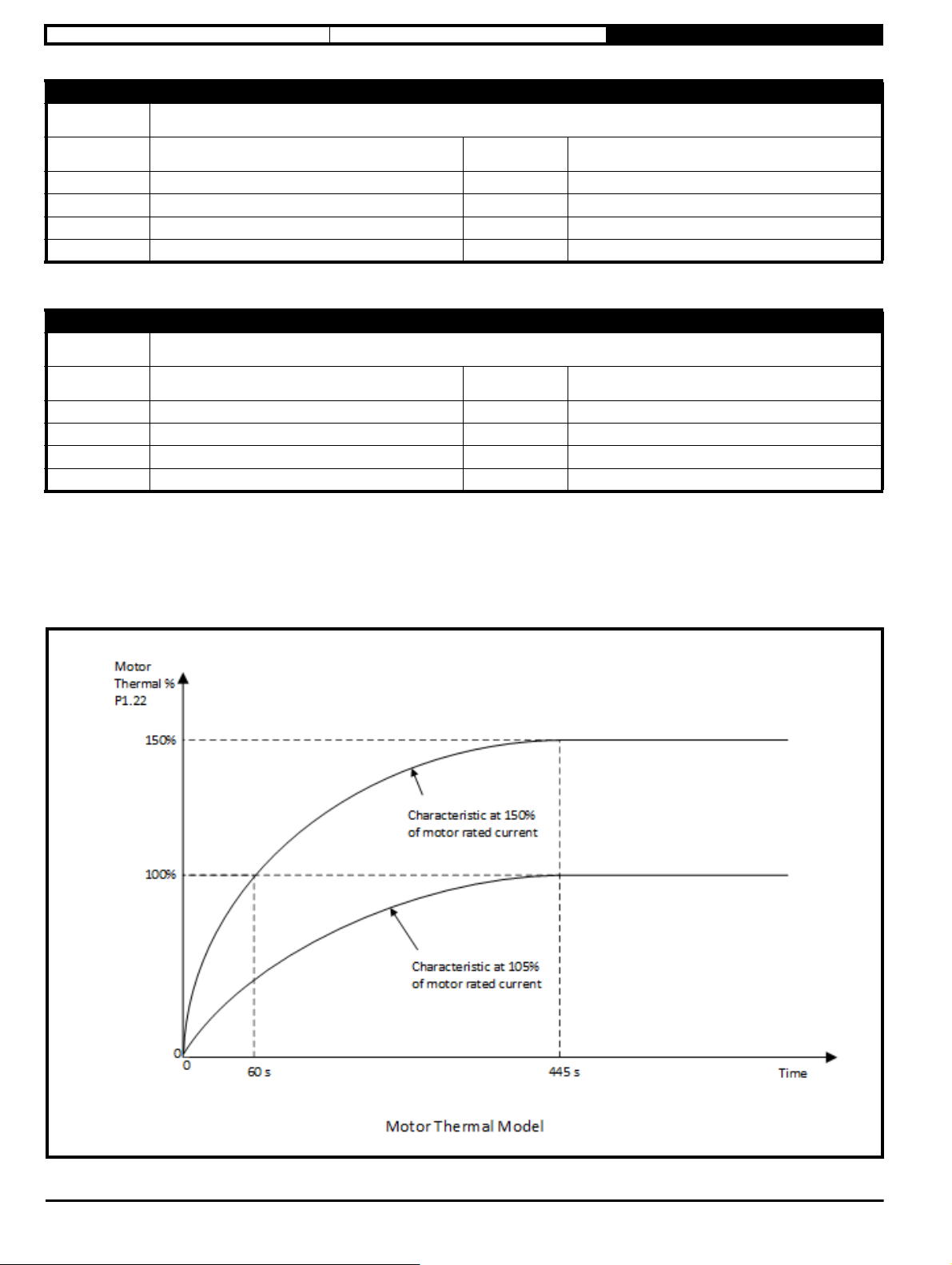
P1.22 Motor Thermal Percentage
The percentage of the maximum allowed temperature for the motor
0
8 Bit Power Down Save
Standard
RO, ND, NC, BU
Maximum
Units
Update Rate
Decimal Places
100
%
0
The drive estimates the percentage of the motor maximum temperature from the output current and uses this to limit the overload period to protect the
motor. This function allows a longer overload period when the motor is cool and reduces the allowable overload period as the motor heats.
The overload period depends on the percentage overload current and motor starting temperature.
The action taken by the drive can be set in Thermal Protection Action (P3.21).
If Thermal Protection Action (P3.21) is set to Limit, the output current will be limited if this parameter > 90%.
If Thermal Protection Action (P3.21) is set to Error, the error will occur when this parameter = 100%.
An alarm is indicated if this percentage is >95% and cleared when <75% (Alarm Indicators (P1.09)).
24 Commander S100 USer Guide
Page 25

Safety information Electrical installation Drive Parameters
Parameter
Short
description
Minimum
Default
Typ e
Display Format
Coding
P1.23 Drive Thermal Percentage
The percentage of the maximum allowed temperature in the drive
0
8 Bit Volatile
Standard
RO, ND, NC, BU
Maximum
Units
Update Rate
Decimal Places
100
%
0
The drive measures its internal temperature which changes depending on the output current. This is displayed as a percentage of the maximum
allowed drive temperature.
The action taken by the drive can be set in Thermal Protection Action (P3.21).
If Thermal Protection Action (P3.21) is set to Limit, the output current will be limited if this parameter > 90%.
If Thermal Protection Action (P3.21) is set to Error, the error will occur when this parameter = 100%.
An alarm is indicated if this percentage is >95% and cleared when <75% (Alarm Indicators (P1.09)).
Parameter
Short
description
Minimum
Default
Typ e
Display Format
Coding
P1.24 DC Bus Voltage
The voltage on the DC Bus of the drive
0
16 Bit Volatile
Standard
RO, FI, VM, ND, NC
Maximum
Units
Update Rate
Decimal Places
Maximum D.C. Link Voltage
(110 V, 200 V Drives = 415 V, 400 V Drives = 830 V)
V
0
Displays the voltage on the DC Bus of the drive. This is the Supply Voltage x √2.
This voltage must exceed the under-voltage (UV) level for the drive to run.
100 V and 200 V drives (UV) = 175 V
400 V UV = 330 V
Parameter
Short
description
Minimum
Default
Typ e
Display Format
Coding
Bit 0 T11 Digital IO 1 Set to 1 if the input or output is active
Bit 1 T12 Digital Input 2 Set to 1 if the input is active
Bit 2 T13 Digital Input 3 Set to 1 if the input is active
Bit 3 T14 Digital Input 4 Set to 1 if the input is active
Bit 4 T15 Digital Input 5 Set to 1 if the input is active when a digital input, otherwise 0
Bit 5 T2 Analog Input 1 Set to 1 if the input is active
P1.25 Digital IO Indicators
A set of indicators that represent the status of the digital I/O
0
(Display: 00000000)
8 Bit Volatile
Binary
RO, ND, NC, BU
Maximum
Units
Update Rate
Decimal Places
255
(D i spla y : 11111111)
0
Bit 6 T4 Analog Input 2 Set to 1 if the input is active
Bit 7 T41 Relay Set to 1 if the relay is active
Commander S100 User Guide 25
Page 26
Safety information Electrical installation Drive Parameters
Parameter
Short
description
Minimum
Default
Typ e
Display Format
Coding
P1.26 Parameter 1 Saved Value on Error
The value of a designated parameter when the latest error occurred
-32768
16 Bit Power Down Save
Standard
RO, ND, NC
Maximum
Units
Update Rate
Decimal Places
32767
Write on Error
0
If an error occurs the drive will save the value of the parameter selected by Parameter 1 Save on Error Selector (P4.09). There are two other saved
parameters that behave in the same way, Parameter 2 Saved Value on Error (P1.27) & Parameter 3 Saved Value on Error (P1.28) . All of these
parameters are saved at the point when an Error (P1.29) occurs.
Parameter
Short
description
Minimum
Default
Typ e
Display Format
Coding
P1.27 Parameter 2 Saved Value on Error
The value of a designated parameter when the latest error occurred
-32768
16 Bit Power Down Save
Standard
RO, ND, NC
Maximum
Units
Update Rate
Decimal Places
32767
Write on Error
0
See Parameter 1 Saved Value on Error (P1.26).
Parameter
Short
description
Minimum
P1.28 Parameter 3 Saved Value on Error
The value of a designated parameter when the latest error occurred
-32768
Maximum
32767
Default
Typ e
Display Format
Coding
16 Bit Power Down Save
Standard
RO, ND, NC
Units
Update Rate
Decimal Places
Write on Error
0
See Parameter 1 Saved Value on Error (P1.26).
Parameter
Short
description
Minimum
Default
Typ e
Display Format
Coding
P1.29 Error
The active or last error to have occurred
0
8 Bit Power Down Save
Standard
RO, ND, NC, BU
Maximum
Units
Update Rate
Decimal Places
255
Write on Error
0
Displays the active error, or if there is no error currently active this is the last error to have occurred.
Parameter
Short
description
Minimum
Default
Typ e
Display Format
Coding
P1.30 Error History 1
The previous error to P1.29
0
8 Bit Power Down Save
Standard
RO, ND, NC, BU
Maximum
Units
Update Rate
Decimal Places
255
Write on Error
0
Displays the second from last error to have occurred.
26 Commander S100 USer Guide
Page 27
Safety information Electrical installation Drive Parameters
Parameter
Short
description
Minimum
Default
Typ e
Display Format
Coding
P1.31 Error History 2
The previous error to P1.30
0
8 Bit Power Down Save
Standard
RO, ND, NC, BU
Displays the third from last error to have occurred.
Parameter
Short
description
Minimum
Default
Typ e
Display Format
Coding
P1.32 Error History 3
The previous error to P1.31
0
8 Bit Power Down Save
Standard
RO, ND, NC, BU
Displays the fourth from last error to have occurred.
Maximum
Units
Update Rate
Decimal Places
Maximum
Units
Update Rate
Decimal Places
255
Write on Error
0
255
Write on Error
0
Commander S100 User Guide 27
Page 28

Safety information Electrical installation Drive Parameters
Parameter
Short
description
Minimum
Default
Typ e
Display Format
Coding
P1.33 Drive Diagnostic
Provides an indication of why the drive is not running
0
8 Bit Volatile
Standard
RO, ND, NC, BU
Maximum
Units
Update Rate
Decimal Places
15
Write on Error
0
This parameter is a diagnostic parameter that helps identify what needs to happen in order for the drive to run.
Value Name Description
0 Running Drive is running i.e. No Diagnostic information
1 Inhibited Drive is not enabled. See IO Configuration (Menu 6) and Drive Enable (P4.17).
2 Ready Drive is enabled but has not received a Run command. See IO Configuration (Menu 6).
3 Locked Inhibit
4 Ref 1 Setup Ref 1 has been selected but is set to 0 Hz. See Frequency Reference 1 Selector (P2.21)
5 Ref 2 Setup Ref 2 has been selected but is set to 0 Hz. See Frequency Reference 1 Selector (P2.21)
Drive has stopped and is waiting for the run command to be removed before it can be made to run again (such as after an
Auto-tune has finished)
6 Ref 3 Setup Ref 3 has been selected but is set to 0 Hz. See Frequency Reference 1 Selector (P2.21)
7 Ref 4 Setup Ref 4 has been selected but is set to 0 Hz. See Frequency Reference 1 Selector (P2.21)
8 Up/Down Ref The Up/Down Reference has been selected, but not configured. See Up/Down Percent Configuration (P2.14)
9 Freq Ref The Frequency Reference has been selected, but has not been configured See T15 Digital Input 5 Type (P6.05)
10 PID Enable
11 PID Ref PID Percent has been selected, but the PID Reference has not been configured See PID Reference Selector (P5.03)
12 PID Fbk PID Percent has been selected, but the PID Feedback has not been configured See PID Feedback Selector (P5.04)
13
14 PID Freq Ref
15 PID Freq Fbk
PID Up/Down
Ref
PID Percent has been selected, but the PID has not been enabled.
See PID Controller (Menu 5).
PID Percent has been selected and the PID Reference is set to Up/Down, but the Up/Down Reference has not been
configured. See Up/Down Percent Configuration (P2.14)
PID Percent has been selected and the PID Reference is set to Frequency input, but the Frequency input has not been
configured. See T15 Digital Input 5 Type (P6.05)
PID Percent has been selected and the PID feedback is set to Frequency input, but the Frequency input has not been
configured. See T15 Digital Input 5 Type (P6.05)
28 Commander S100 USer Guide
Page 29

Safety information Electrical installation Drive Parameters
3.10.2 Menu 2 - Reference & Ramps
This menu groups together parameters used to define the reference input to the drive (the speed demand) and the ramp system (how the drive
accelerates and decelerates to the chosen reference). Multiple references can be configured so that the drive can be switched from one reference
input to another using a digital input or communications.
Associated Parameters
• Ramp Input (P1.13)
• Ramp Output (P1.14)
• T2 Analog Input 1 Percentage (P1.15)
• T4 Analog Input 2 Percentage (P1.16)
• T15 Frequency Input Percentage (P1.17)
• Up/Down Percentage (P1.18)
• PID Percentage (P1.19)
• Enable/Run Configuration (P6.13)
Parameter
Short
description
Minimum
Default
Typ e
Display Format
Coding
P2.01 Minimum Frequency Limit
Defines the minimum frequency the drive can be commanded to run at
0.0
0.0
16 Bit User Save
Standard
RW, BU
Maximum
Units
Update Rate
Decimal Places
300.0
Hz
Background read
1
This parameter is the minimum limit applied to the selected reference. If the value set is higher than the Maximum Frequency Limit (P2.02) the
reference will be limited to the maximum. This is a symmetrical limit for both directions of rotation.
This is used for scaling the range of percentage inputs.
Commander S100 User Guide 29
Page 30

Safety information Electrical installation Drive Parameters
NOTE
Parameter
Short
description
Minimum
Default
Typ e
Display Format
Coding
P2.02 Maximum Frequency Limit
Defines the maximum frequency the drive can be commanded to run at
0.0
See exceptions below
16 Bit User Save
Standard
RW, BU
Maximum
Units
Update Rate
Decimal Places
300.0
Hz
Background read
1
Region Default Value
50Hz 50.0
60Hz 60.0
This parameter is applied to the selected reference. If the Minimum Frequency Limit (P2.01) is higher than this parameter the reference will be limited
to the maximum. This is a symmetrical limit for both directions of rotation.
This is used for scaling the range of percentage inputs.
Output Frequency (P1.01) can be higher than the limit due to motor slip compensation
Parameter
Short
description
Minimum
Default
Typ e
Display Format
Coding
P2.03 Frequency Reference Configuration
Common configurations for speed references used by the drive
0
1
8 Bit User Save
Standard
RW, TE, BU
Maximum
Units
Update Rate
Decimal Places
9
0
Value Text Description
0 Custom The reference system can be entirely customised
1 Local/Remote
2 Voltage/Preset Input
3 Current/Preset Input
4Presets
5 Keypad The keypad keys are used to control the frequency Up/Down percentage (P1.18)
6 Terminal Up/Down Digital input 5 and digital input 1 are used to control the Up/Down percentage (P1.18)
7 Frequency Input A frequency input on digital input 5
8 PID Voltage Ref.
9 PID + Feed Forward
A current input on Analog input 1 and a voltage input on Analog input 2. Digital input 5 is used to
select between them.
A voltage input on Analog input 1. Digital input 5 and digital input 1 are used as binary selectors to
choose between it and three preset frequency references
A current input on Analog input 1. Digital input 5 and digital input 1 are used as binary selectors to
choose between it and three preset frequency references
Digital input 5 and digital input 1 are used as the binary selectors to choose between the four
preset frequency references
A Voltage input on Analog input 1 as the reference, and a current input on Analog input 2 as the
feedback. The PID output is used as the drive reference
A Voltage input on Analog input 1 as the Feed Forward, and a current input on Analog input 2 as
the feedback, the reference is fixed. The PID output is used as the drive reference
30 Commander S100 USer Guide
Page 31

Safety information Electrical installation Drive Parameters
The table above shows the options to quickly set up the reference system for a specific application. The assignments are made on exit of the
parameter (Press settings key or Back in Marshal). The table below indicates the parameters that are set up and the values written.
Value P2.14 P2.20 P2.21 P2.22 P2.23 P2.24 P5.03 P5.04 P5.05 P5.11 P6.01 P6.02 P6.04 P6.05 P6.16 P6.20
0 N/A N/A N/A N/A N/A N/A N/A N/A N/A N/A N/A N/A N/A N/A N/A N/A
1 N/A 0 6 7 N/A N/A N/A N/A N/A N/A 2 0 N/A 0 N/A 10
2 N/A 0 6 2 3 4 N/A N/A N/A N/A 0 N/A 0 0 11 10
3 N/A 0 6 2 3 4 N/A N/A N/A N/A 2 N/A 0 0 11 10
4 N/A 0 1 2 3 4 N/A N/A N/A N/A N/A N/A 0 0 11 10
5 3 1 5 N/A N/A N/A N/A N/A N/A N/A N/A N/A N/A N/A N/A N/A
6 015N/AN/AN/AN/AN/AN/AN/AN/AN/A0087
7 N/A 1 8 N/A N/A N/A N/A N/A N/A N/A N/A N/A N/A 1 N/A N/A
8 N/A19N/AN/AN/A120105N/AN/AN/AN/A
9 N/A19N/AN/AN/A521105N/AN/AN/AN/A
N/A - No value written
Commander S100 User Guide 31
Page 32
Safety information Electrical installation Drive Parameters
Parameter
Short
description
Minimum
Default
Typ e
Display Format
Coding
P2.04 Stopping Mode Selector
Defines how the motor is controlled when the run signal is removed from the drive
0
1
8 Bit User Save
Standard
RW, TE, BU
Maximum
Units
Update Rate
Decimal Places
4
400 ms
0
Value Text Description
0 Coast Remove power from the motor and allow to spin under control of the load
1Ramp
2 Ramp & Brake
3 DC Brake, 0Hz detect
4 Timed DC Brake
Motor slows down to 0 Hz under control of the drive. The drive waits for 1 second before it can be
restarted
Ramp stop and then DC injection at a level defined by DC Braking Current Level (P3.13) for a time
defined by DC Braking Time (P3.14). Can prevent motor from moving after the deceleration
Low frequency current injection with detection of low speed and then DC injection at a level defined
by DC Braking Current Level (P3.13) for a time defined by DC Braking Time (P3.14)
DC injected at a level defined by DC Braking Current Level (P3.13) for a time defined by DC
Braking Time (P3.14)
32 Commander S100 USer Guide
Page 33
Safety information Electrical installation Drive Parameters
Parameter
Short
description
Minimum
Default
Typ e
Display Format
Coding
P2.05 S-Ramp Percentage
Defines the profile of the S ramp system as a percentage
0.0
0.0
16 Bit User Save
Standard
RW, BU
Maximum
Units
Update Rate
Decimal Places
51.0
400 ms
1
As default this parameter is set to 0 which means that the S-Ramp profile is not active. To enable an S-Ramp profile a percentage must be set.
The parameter specifies the percentage of the ramp to maximum frequency that includes the S ramp profile. The maximum frequency is defined by
Maximum Frequency Limit (P2.02).
It should be noted that as this parameter is increased, the time to ramp to maximum frequency does not change, instead the maximum acceleration
rate in the centre of the profile increases which causes a steeper linear portion at the centre of the profile.
Parameter
Short
description
Minimum
Default
Typ e
Display Format
Coding
P2.06 Acceleration Rate 1
Defines the acceleration time from 0 Hz to the maximum frequency limit
0.0
5.0
16 Bit User Save
Standard
RW, BU
Maximum
Units
Update Rate
Decimal Places
6000.0
s
400 ms
1
Specified in seconds from 0 Hz to Maximum Frequency Limit (P2.02) for a linear ramp. An acceleration rate applies when the frequency is changing
away from 0 Hz.
Commander S100 User Guide 33
Page 34
Safety information Electrical installation Drive Parameters
Parameter
Short
description
Minimum
Default
Typ e
Display Format
Coding
P2.07 Deceleration Rate 1
Defines the deceleration time from the maximum frequency limit to 0 Hz
0.0
10.0
16 Bit User Save
Standard
RW, BU
Maximum
Units
Update Rate
Decimal Places
6000.0
s
400 ms
1
Specified in seconds from Maximum Frequency Limit (P2.02) to 0 Hz for a linear ramp. A deceleration rate applies when the frequency is changing
towards 0 Hz.
The drive may increase the ramp time due to the DC bus voltage controller, see Deceleration Ramp Type (P2.11)
Parameter
Short
description
Minimum
Default
Typ e
Display Format
Coding
P2.08 Acceleration Rate 2
Defines the acceleration time from 0 Hz to the maximum frequency limit
0.0
5.0
16 Bit User Save
Standard
RW, BU
Maximum
Units
Update Rate
Decimal Places
6000.0
s
400 ms
1
Specified in seconds from 0 Hz to Maximum Frequency Limit (P2.02) for a linear ramp. An acceleration rate applies when the frequency is changing
away from 0 Hz.
To select between Acceleration Rate 1 (P2.06) and Acceleration Rate 2 (P2.08) use Ramp Rate Selector (P2.10).
Parameter
Short
description
Minimum
Default
Typ e
Display Format
Coding
P2.09 Deceleration Rate 2
Defines the deceleration time from the maximum frequency limit to 0 Hz
0.0
10.0
16 Bit User Save
Standard
RW, BU
Maximum
Units
Update Rate
Decimal Places
6000.0
s
400 ms
1
Specified in seconds from Maximum Frequency Limit (P2.02) to 0 Hz for a linear ramp. A deceleration rate applies when the frequency is changing
towards 0 Hz.
The drive may increase the ramp time due to the DC bus voltage controller, see Deceleration Ramp Type (P2.11) .
To select between Deceleration Rate 1 (P2.07) and Deceleration Rate 2 (P2.09) use Ramp Rate Selector (P2.10).
34 Commander S100 USer Guide
Page 35
Safety information Electrical installation Drive Parameters
Parameter
Short
description
Minimum
Default
Typ e
Display Format
Coding
P2.10 Ramp Rate Selector
Selects between ramp rate 1 or 2
0
0
8 Bit User Save
Standard
RW, BU
Maximum
Units
Update Rate
Decimal Places
Used to define the selection of the required ramp rates.
Value Description
The Digital Input Function Ramp Select (12) is used to select between acceleration / deceleration rates 1 and 2 ( see IO Configuration (06) ).
0
1 Acceleration Rate 1 (P2.06) and Deceleration Rate 1 (P2.07) are used by the ramp system
2 Acceleration Rate 2 (P2.08) and Deceleration Rate 2 (P2.09) are used by the ramp system
Parameter
Short
description
Minimum
Default
Typ e
Display Format
Coding
This function can be selected for any of the digital inputs. If the Digital Input Function has not been
configured, Acceleration Rate 1 (P2.06) and Deceleration Rate 1 (P2.07) are used by the ramp system
P2.11 Deceleration Ramp Type
Defines the type of deceleration required when stopping
0
0
8 Bit User Save
Standard
RW, TE, BU
Maximum
Units
Update Rate
Decimal Places
2
400 ms
0
2
400 ms
0
Value Text Description
0 Fast Based on the deceleration rate selected
1 Standard Ramp Deceleration is controlled to prevent a DC Bus over voltage
2 Standard Ramp + Motor Deceleration is controlled to prevent a DC Bus over voltage, with increased losses in the motor
Defines the ramp type used for decelerating, three types are available. Fast ramp decelerates at the selected deceleration rate, and if the energy
returned from the motor is too great the drive will generate an Over Voltage error due to the DC Bus voltage rising above its permitted level.
In Standard Ramp modes the drive limits the deceleration rate to maintain the DC Bus voltage at the value set in Standard Ramp Voltage (P2.12).
The Standard Ramp Plus Motor also increases the voltage applied to the motor by 20% above the normal level to increase the losses in the motor
and thus reduce the deceleration time that can be achieved. Note that with applications requiring a lot of deceleration cycles this could overheat the
motor.
Commander S100 User Guide 35
Page 36
Safety information Electrical installation Drive Parameters
NOTE
Parameter
Short
description
Minimum
Default
Typ e
Display Format
Coding
P2.12 Standard Ramp Voltage
DC bus voltage controller will attempt to hold this voltage during deceleration
0
See exceptions below
16 Bit User Save
Standard
RW, VM, RA, BU
Maximum
Units
Update Rate
Decimal Places
Maximum D.C. Link Voltage
(110 V, 200 V Drives = 415 V, 400 V Drives = 830 V)
V
400 ms
0
Voltage Region Default Value
400V 50Hz 375
400V All 750
400V 60Hz 775
During deceleration power is fed into the DC bus of the drive which causes the voltage to rise. When the voltage reaches the level defined by this
parameter the DC bus voltage controller becomes active and limits the deceleration rate to maintain this voltage until the energy returning no longer
causes the DC Bus voltage to rise, see Deceleration Ramp Type (P2.11) . Increasing Current Controller Gain (P3.23) improves the controller action,
but this parameter may also need to be reduced to prevent over voltage errors when decelerating high inertia loads.
This parameter should not be set lower than the maximum expected peak mains voltage of the incoming supply.
Parameter
Short
description
Minimum
Default
Typ e
Display Format
Coding
P2.13 Jog Frequency
Frequency when jog is enabled
-MAXIMUM FREQUENCY LIMIT (P2.02)
1.5
16 Bit User Save
Standard
RW, VM
Maximum
Units
Update Rate
Decimal Places
MAXIMUM FREQUENCY LIMIT (P2.02)
Hz
20 ms
1
Defines the frequency when jog is active, the currently selected acceleration and deceleration rates are used.
36 Commander S100 USer Guide
Page 37
Safety information Electrical installation Drive Parameters
NOTE
Parameter
Short
description
Minimum
Default
Typ e
Display Format
Coding
Value Text Description
0 Reset Up/Down Percentage set to 0 at power up
1 Last Up/Down Percentage saved and restored at power up
2 Preset 1 Up/Down Percentage set to Preset Reference 1 (P2.16) at power up
3 Keypad and Reset Keypad Up/Down control enabled and Up/Down Percentage set to 0 at power up
4 Keypad and Last Keypad Up/Down control enabled and Up/Down Percentage saved and restored at power up
5 Keypad and Preset 1
P2.14 Up/Down Percent Configuration
Defines the behaviour of the Up/Down Percentage at power-up
0
0
8 Bit User Save
Standard
RW, TE, BU
Keypad Up/Down control enabled and Up/Down Percentage set to Preset Reference 1 (P2.16) at
power up
Maximum
Units
Update Rate
Decimal Places
5
0
The first three values are used to define the Up/Down Percentage value at power up only, and the last 3 values define the UP/Down Percentage value
at power up and enable Keypad speed control. If Preset Frequency 1 (P2.16) is selected as the power up reference, the value set in Up/Down
Percentage (P1.18) at power up is Preset Frequency 1 (P2.16) / Maximum Frequency Limit (P2.02).
Parameter
Short
description
Minimum
Default
Typ e
Display Format
Coding
P2.15 Up/Down Percentage Time to Max
Defines the rate at which the Up/Down reference changes
0
20
8 Bit User Save
Standard
RW, BU
Maximum
Units
Update Rate
Decimal Places
250
s
0
The rate of change of Up/Down Percentage (P1.18) is defined by Up/Down Percentage Time to Max (P2.15) which gives the number of seconds to
change from 0 % to 100%.
If the keypad reference mode is active, then this rate is applied when holding the Up or Down while selecting the reference. Single presses of Up or
Down will change the value by 0.1%.
Parameter
Short
description
Minimum
Default
Typ e
Display Format
Coding
P2.16 Preset Frequency 1
Defines the frequency for preset reference 1
-MAXIMUM FREQUENCY LIMIT (P2.02
5.0
16 Bit User Save
Standard
RW, VM
Maximum
Units
Update Rate
Decimal Places
MAXIMUM FREQUENCY LIMIT (P2.02)
Hz
20 ms
1
A frequency that can be used as a fixed reference by the reference select system.
To use a preset speed as a drive frequency reference, it should be selected in a Frequency Reference Selector parameter (P2.21 to P2.24).
Commander S100 User Guide 37
Page 38

Safety information Electrical installation Drive Parameters
Parameter
Short
description
Minimum
Default
Typ e
Display Format
Coding
P2.17 Preset Frequency 2
Defines the frequency for preset reference 2
-MAXIMUM FREQUENCY LIMIT (P2.02)
10.0
16 Bit User Save
Standard
RW, VM
Maximum
Units
Update Rate
Decimal Places
A frequency that can be used as a fixed reference by the reference select system.
Parameter
Short
description
Minimum
Default
Typ e
Display Format
Coding
P2.18 Preset Frequency 3
Defines the frequency for preset reference 3
-MAXIMUM FREQUENCY LIMIT (P2.02)
25.0
16 Bit User Save
Standard
RW, VM
Maximum
Units
Update Rate
Decimal Places
A frequency that can be used as a fixed reference by the reference select system.
Parameter
Short
description
Minimum
Default
Typ e
Display Format
Coding
P2.19 Preset Frequency 4
Defines the frequency for preset reference 4
-MAXIMUM FREQUENCY LIMIT (P2.02)
50.0
16 Bit User Save
Standard
RW, VM
Maximum
Units
Update Rate
Decimal Places
MAXIMUM FREQUENCY LIMIT (P2.02)
Hz
20 ms
1
MAXIMUM FREQUENCY LIMIT (P2.02)
Hz
20 ms
1
MAXIMUM FREQUENCY LIMIT (P2.02)
Hz
20 ms
1
A frequency that can be used as a fixed reference by the reference select system.
Parameter
Short
description
Minimum
Default
Typ e
Display Format
Coding
P2.20 Frequency Reference 1 to 4 Selector
Defines which reference is used by the reference system
0
0
8 Bit User Save
Standard
RW, TE, BU
Maximum
Units
Update Rate
Decimal Places
4
20 ms
0
Value Text Description
0 Binary Digital input functions can be configured to select reference 1, 2, 3 or 4 using Digital inputs
1 Freq. Reference 1 The reference selected by Reference 1 Select (2.21) will be used
2 Freq. Reference 2 The reference selected by Reference 2 Select (2.22) will be used
3 Freq. Reference 3 The reference selected by Reference 3 Select (2.23) will be used
4 Freq. Reference 4 The reference selected by Reference 4 Select (2.24) will be used
38 Commander S100 USer Guide
Page 39
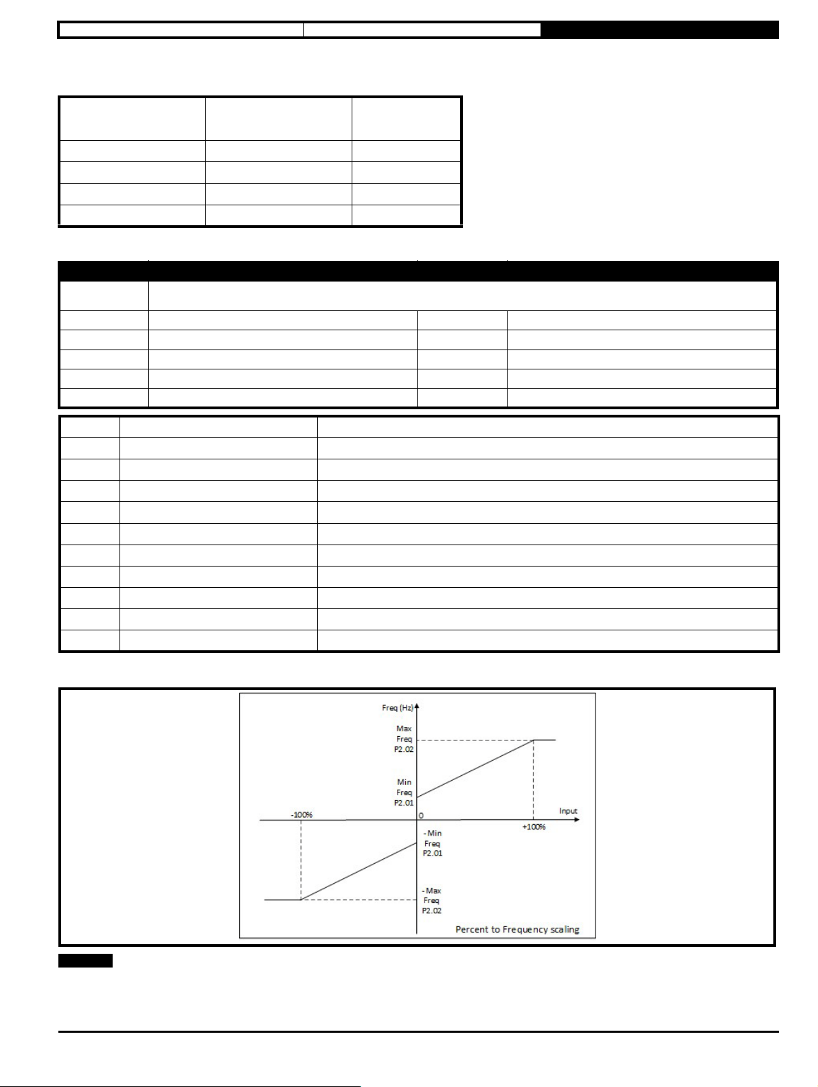
Safety information Electrical installation Drive Parameters
NOTE
One of the 4 frequency references to be used by the reference system is selected by this parameter. If this parameter is set to 0, any digital input can
be configured to select a reference by setting their input function to Reference Selector 0 or Reference Selector 1, as per the following table:
Reference Selector Bit 1 Reference Selector Bit 0
0 0 Reference 1
0 1 Reference 2
1 0 Reference 3
1 1 Reference 4
Reference
selected
If no digital inputs are configured as a reference selector bit, the reference selector values are 0 and therefore Reference 1 will be used.
Parameter
Short
description
Minimum
Default
Typ e
Display Format
Coding
P2.21 Frequency Reference 1 Selector
Defines which Frequency reference or Percentage reference is selected as reference 1
0
6
8 Bit User Save
Standard
RW, TE, BU
Maximum
Units
Update Rate
Decimal Places
9
20 ms
0
Value Text Description
0 None A fixed reference of 0Hz
1 Preset 1 The frequency reference is defined by Preset Frequency 1 (P2.16)
2 Preset 2 The frequency reference is defined by Preset Frequency 2 (P2.17)
3 Preset 3 The frequency reference is defined by Preset Frequency 3 (P2.18)
4 Preset 4 The frequency reference is defined by Preset Frequency 4 (P2.19)
5 Up/Down Percent The frequency reference is derived from the Up/Down Percentage (P1.18)
6 Analog 1 Percent The frequency reference is derived from Analog Percentage 1 (P1.15)
7 Analog 2 Percent The frequency reference is derived from Analog Percentage 2 (P1.16)
8 Frequency Input % The frequency reference is derived from the frequency input Percentage (P1.17)
9 PID Percent The frequency reference is derived from the PID output Percentage (P1.19)
For inputs 0 - 4, the frequency references are transferred directly into the reference system. For inputs 5 - 9, the percentages selected are converted
to Hz using parameters Minimum Frequency Limit (P2.01) and Maximum Frequency Limit (P2.02).
If Frequency Reference 1 Selector (P2.21) is set to 0 Hz, the drive will run at the minimum frequency limit.
The value of this parameter can be set by Frequency Reference Configuration (P2.03).
This parameter cannot have the same setting as another frequency reference selector parameter.
Commander S100 User Guide 39
Page 40
Safety information Electrical installation Drive Parameters
NOTE
NOTE
NOTE
Parameter
Short
description
Minimum
Default
Typ e
Display Format
Coding
P2.22 Frequency Reference 2 Selector
Defines which Frequency reference or Percentage reference is selected as reference 2
0
7
8 Bit User Save
Standard
RW, TE, BU
Maximum
Units
Update Rate
Decimal Places
See Frequency Reference 1 Selector (P2.21).
The value of this parameter can be set by Frequency Reference Configuration (P2.03).
Parameter
Short
description
Minimum
Default
Typ e
Display Format
Coding
P2.23 Frequency Reference 3 Selector
Defines which Frequency reference or Percentage reference is selected as reference 3
0
0
8 Bit User Save
Standard
RW, TE, BU
Maximum
Units
Update Rate
Decimal Places
See Frequency Reference 1 Selector (P2.21).
9
20 ms
0
9
20 ms
0
The value of this parameter can be set by Frequency Reference Configuration (P2.03).
Parameter
Short
description
Minimum
Default
Typ e
Display Format
Coding
P2.24 Frequency Reference 4 Selector
Defines which Frequency reference or Percentage reference is selected as reference 4
0
0
8 Bit User Save
Standard
RW, TE, BU
Maximum
Units
Update Rate
Decimal Places
See Frequency Reference 1 Selector (P2.21).
The value of this parameter can be set by Frequency Reference Configuration (P2.03).
9
20 ms
0
40 Commander S100 USer Guide
Page 41
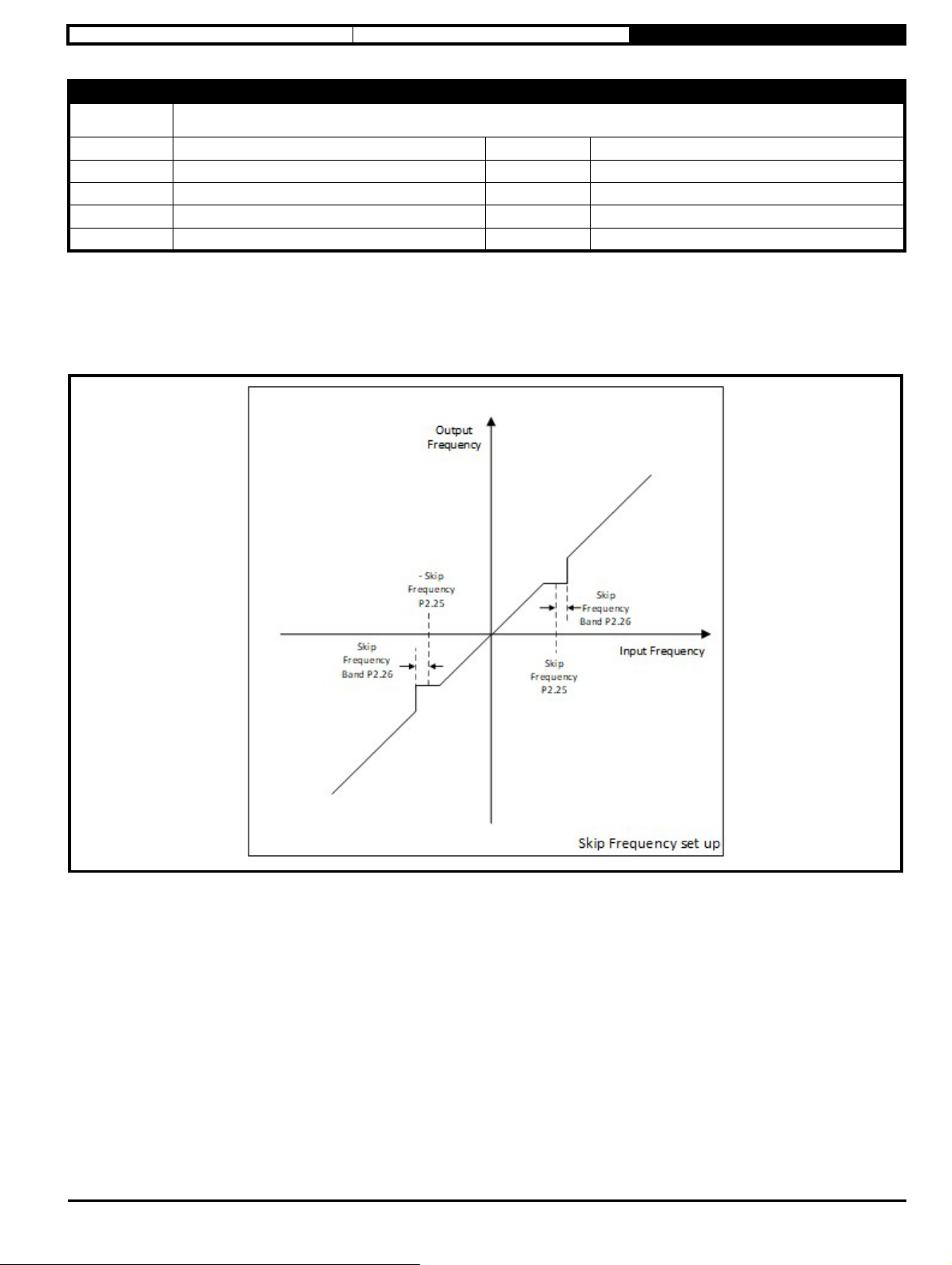
Safety information Electrical installation Drive Parameters
Parameter
Short
description
Minimum
Default
Typ e
Display Format
Coding
P2.25 Skip Frequency
Defines the reference frequency to skip
0.0
0.0
16 Bit User Save
Standard
RW, VM, BU
Maximum
Units
Update Rate
Decimal Places
MAXIMUM FREQUENCY LIMIT (P2.02)
Hz
20 ms
1
By default, this parameter is set to 0 which means that the skip frequency function is not active. To enable the skip frequency function a value must be
specified in this parameter.
The skip reference function is available to prevent continuous operation within a specified frequency range (i.e. where mechanical resonance may
occur). Skip Frequency Band (P2.26) defines the range either side of the value set here over which references are rejected in either direction. The
actual rejection band is therefore twice that defined by Skip Frequency Band (P2.26) with this parameter at the centre of the band. When the selected
reference is within the rejection band the lower limit of the band is passed through the filter so that reference is always less in magnitude than
demanded.
Commander S100 User Guide 41
Page 42

Safety information Electrical installation Drive Parameters
3.10.3 Menu 3 - Motor Setup
This menu contains parameters relating to motor setup and control.
Associated Parameters
• Output Frequency (P1.01)
• Output Voltage (P1.02)
• Output Power (P1.03)
• Motor RPM (P1.04)
• Output Current (P1.06)
• Torque Producing Current (P1.07)
• Percentage Load (P1.08)
• Motor Thermal Percentage (P1.22)
• Motor Thermal Percentage (P1.23)
42 Commander S100 USer Guide
Page 43

Safety information Electrical installation Drive Parameters
NOTE
Parameter
Short
description
Minimum
Default
Typ e
Display Format
Coding
P3.01 Motor Rated Current
Set to the rated current of the motor from the motor nameplate
0.00
6.80
16 Bit User Save
Standard
RW, VM, RA, BU
Maximum
Units
Update Rate
Decimal Places
Drive Rated Current
A
400 ms
2
Motor Rated Current must be set to the maximum continuous current of the motor (taken from the motor name plate). It is used as follows:
1. In the motor control algorithms
2. To define the range of the current limits - the current limits can be set higher than default if the motor rated current is less than the drive rating.
See Motor Output Current Limit (P3.17) )
3. In determining Percentage Load (P1.08)
4. To define the rated operating conditions for motor thermal protection. See Motor Thermal Percentage (P1.22)
Parameter
Short
description
Minimum
Default
Typ e
Display Format
Coding
P3.02 Motor Rated Speed
Set to the rated current of the motor from the motor nameplate
0
See exceptions below
16 Bit User Save
Standard
RW
Maximum
Units
Update Rate
Decimal Places
18000
rpm
400 ms
0
Region Default Value
50Hz 1500
60Hz 1800
Motor rated Speed is used together with Motor Rated Frequency (P3.15) to calculate the slip of the machine and Number Of Motor Poles (P3.16).
Rated Slip (Hz) = Motor Rated Frequency (P3.15) - ( Pole Pairs x Motor Rated Speed (P3.02) / 60)
Pole Pairs = Motor Poles / 2 either calculated automatically, or read from Number Of Motor Poles (P3.16)
Slip compensation adjusts the output frequency to compensate for the change in slip with the load in the motor.
Slip Compensation (Hz) = Rated Slip x Torque Producing Current (P1.07) / I
Trated
I
= Torque Rated Current. See Motor Output Current Limit (P3.17)
Slip compensation is disabled by setting Motor Rated Speed (P3.02)
Trated
≥ 0
If spinning start is required (i.e. Catch An Already Spinning Motor (P3.11) 1) then Motor Rated Speed should be set correctly for the motor.
If motor rated Speed is set to 0, Number Of Motor Poles (P3.16) must be set up Manually for Motor RPM (P1.04) to indicate the correct speed.
Commander S100 User Guide 43
Page 44

Safety information Electrical installation Drive Parameters
Parameter
Short
description
Minimum
Default
Typ e
Display Format
Coding
P3.03 Motor Rated Voltage
Set to the rated current of the motor
0
See exceptions below
16 Bit User Save
Standard
RW, VM, RA, BU
Maximum
Units
Update Rate
Decimal Places
Drive Rated Voltage
V
400 ms
0
Voltage Region Default Value
400 V 50 Hz 230
400 V All 400
400 V 60 Hz 460
Motor Rated Voltage must be set to the voltage rating of the motor (taken from the motor name plate).
Motor Rated Voltage and Motor Rated Frequency (P3.15) define the frequency to voltage characteristic applied to the motor. See Motor Control Mode
(P3.05) for more details.
Parameter
Short
description
Minimum
Default
Typ e
Display Format
Coding
P3.04 Motor Rated Power Factor
Set to the rated power factor of the motor (cosΦ)
0.00
0.80
8 Bit User Save
Standard
RW, RA, BU
Maximum
Units
Update Rate
Decimal Places
1.00
400 ms
2
Motor Rated Power Factor is the rated power factor of the machine, cos φ (taken from the motor name plate). Motor Rated Power Factor is used
to calculate the rated torque producing current, I
Parameter
Short
description
Minimum
Default
Typ e
Display Format
Coding
P3.05 Motor Control Mode
Defines the mode used to set the output voltage
0
1
8 Bit User Save
Standard
RW, TE, BU
. See Motor Output Current Limit (P3.17).
Trated
Maximum
Units
Update Rate
Decimal Places
2
400 ms
0
Value Text Description
0 Resistance Comp A linear frequency to voltage characteristic with vector based stator resistance compensation
1 Linear V to F A fixed linear frequency to voltage characteristic
2 Square V to F A fixed square frequency to voltage characteristic
This parameter defines the voltage characteristic applied to the motor. Three control modes are available, Resistance Compensation (0), linear V to
F with boost (1), and Square V to F with boost (2).
The default mode of linear V to F is suitable for most applications. For fan and pump applications the Square V to F mode can be selected which
matches the characteristic of the load. For applications that require good torque performance the Resistance Compensation mode should be used.
For this mode of operation an auto-tune should be carried out to measure the stator resistance of the motor, or the resistance should be set up
Manually. An auto-tune can be carried out with Perform Auto-tune (P3.09).
44 Commander S100 USer Guide
Page 45

Safety information Electrical installation Drive Parameters
For Linear V to F, the V-F characteristic can be adjusted at two points, 0Hz where the starting boost voltage is set
in Motor Starting Boost (P3.06), and Motor Starting Boost End Frequency (P3.08), Motor Starting Boost End Voltage (P3.07) which is the frequency
and voltage point at which the boost level is tapered too.
From the second adjustable point the voltage rises linearly towards the Motor Rated Voltage (P3.03) at Motor Rated Frequency (P3.15).
Above Motor Rated Frequency (P3.15) the voltage on the motor is constant and the field strength in the motor reduces as the frequency is increased.
For Square V to F, only the starting boost is adjustable and the voltage output follows a square law from this point until the voltage reaches Motor
Rated Voltage (P3.03) at Motor Rated Frequency (P3.15). At frequencies above this the motor voltage is constant.
Commander S100 User Guide 45
Page 46

Safety information Electrical installation Drive Parameters
NOTE
Parameter
Short
description
Minimum
Default
Typ e
Display Format
Coding
P3.06 Motor Starting Boost
Defines the level of voltage boost at 0 Hz when using Linear V to F
0.0
5.0
8 Bit User Save
Standard
RW, BU
Maximum
Units
Update Rate
Decimal Places
25.0
%
400 ms
1
Defines the level of voltage boost at 0Hz as a percentage of the Motor Rated Voltage (P3.03) when Motor Control Mode (P3.05) is set to Linear V to
F (1) or Square V to F (2). It can be used to increase low frequency torque performance, but if set too high will cause excessive motor current which
would result in a Motor Overload error.
Parameter
Short
description
Minimum
Default
Typ e
Display Format
Coding
P3.07 Motor Starting Boost End Voltage
Defines the boost end voltage as a percentage of the motor rated voltage
0.0
50.0
16 Bit User Save
Standard
RW, BU
Maximum
Units
Update Rate
Decimal Places
100.0
%
400 ms
1
Defines the level of voltage as a percentage of the Motor Rated Voltage (P3.03) at the Motor Starting Boost End Frequency (P3.08) when Motor
Control Mode (P3.05) is in Linear mode (1). See Motor Control Mode (P3.05).
Parameter
Short
description
Minimum
Default
Typ e
Display Format
Coding
P3.08 Motor Starting Boost End Frequency
Defines the boost end frequency as a percentage of the motor rated frequency
0.0
50.0
16 Bit User Save
Standard
RW, BU
Maximum
Units
Update Rate
Decimal Places
100.0
%
400 ms
1
Defines the frequency as a percentage of the Motor Rated Frequency (P3.15) at which Motor Starting Boost (P3.06) has been faded out when Motor
Control Mode (P3.05) is in Linear (1) mode. See Motor Control Mode (P3.05).
Parameter
Short
description
Minimum
Default
Typ e
Display Format
Coding
P3.09 Perform Auto-tune
Auto-tune test to obtain some of the motor characteristics
0
0
1 Bit Volatile
Standard
RW
Maximum
Units
Update Rate
Decimal Places
1
400 ms
0
A stationary test to measure Stator Resistance (P3.18).
This is only used if P3.05 = Resistance Compensation (0). Or if Catch an Already Spinning Motor (P3.11)
≥ 1.
To perform an auto-tune:
Set this parameter to 1 and run the drive
When the auto-tune sequence is completed successfully the drive is stopped. This parameter is set to 0.
The drive can be restarted by removing the run commands and activating them again.
An auto-tune test cannot be initiated if the drive is in error or the drive inverter is active, i.e. Drive Healthy = 0 or Drive Active = 1 in Drive State
(P1.05).
The auto-tune test relies on the motor being stationary when it is initiated to give accurate results. The motor should also remain stationary during the
test.
46 Commander S100 USer Guide
Page 47

Safety information Electrical installation Drive Parameters
Parameter
Short
description
Minimum
Default
Typ e
Display Format
Coding
P3.10 Energy Optimiser
Enables low energy mode
0
0
1 Bit User Save
Standard
RW
Maximum
Units
Update Rate
Decimal Places
1
0
Energy efficient motor control (sometimes referred to as Dynamic V to F) is intended for applications where power loss should be kept to a minimum
under low load conditions, but dynamic (rapid acceleration) performance is not important. The reduction in power loss under low load conditions is
achieved by increasing the rated frequency (internal to the drive) used to derive the frequency to voltage characteristic. When the function is enabled,
the rated frequency used to derive the output voltage is given by:
Motor Rated Frequency (P3.15) x (2 - |Percentage Load (P1.08)| / 70.0%) ,see diagram below.
Commander S100 User Guide 47
Page 48

Safety information Electrical installation Drive Parameters
Parameter
Short
description
Minimum
Default
Typ e
Display Format
Coding
P3.11 Catch an Already Spinning Motor
Defines the behaviour of the drive when the drive is enabled whilst the motor is rotating
0
0
8 Bit User Save
Standard
RW, TE, BU
Maximum
Units
Update Rate
Decimal Places
3
400 ms
0
Value Text Description
0 Disabled No attempt to detect the motor speed
1 Enabled Detects the motor speed before starting
2 Forwards Only Detects forward motor speed only, starts at 0Hz if motor rotating backwards
3 Reverse Only Detects reverse motor speed only, starts at 0Hz if motor rotating forwards
If it is possible that the motor is spinning when the run command is given then this parameter should be set for the required action. If this parameter
is > 0, a test is carried out to measure the frequency that the motor is running at when the drive enters the run state. The measured frequency is used
to preset Ramp Output (P1.14) and give a smooth start at the motor speed detected. For the test to be successful it is important that the motor
parameters, especially Stator Resistance (P3.18) and Motor Rated Speed (P3.02), are set up correctly.
Parameter
Short
description
Minimum
Default
Typ e
Display Format
Coding
P3.12 PWM Switching Frequency
Increases the maximum frequency the drive is allowed to switch the inverter at to 12 kHz
0
0
1 Bit User Save
Standard
RW
Maximum
Units
Update Rate
Decimal Places
1
400 ms
0
This parameter defines the required switching frequency.
Value Name Description
0 Off The switching frequency used by the inverter will be 4 kHz (default)
1 On The maximum switching frequency used by the inverter will be 12 kHz
Parameter
Short
description
Minimum
Default
Typ e
Display Format
Coding
P3.13 DC Braking Current Level
Defines the level of current used for injection braking
0.0
100.0
16 Bit User Save
Standard
RW, BU
Maximum
Units
Update Rate
Decimal Places
150.0
400 ms
1
Defines the level of current used for injection braking as a percentage of Motor Rated Current (P3.01). Excessive current can cause the motor to
overheat.
48 Commander S100 USer Guide
Page 49
Safety information Electrical installation Drive Parameters
Parameter
Short
description
Minimum
Default
Typ e
Display Format
Coding
P3.14 DC Braking Time
Defines the time during which DC current is injected into the motor during timed injection stopping modes
0.0
1.0
16 Bit User Save
Standard
RW, BU
Maximum
Units
Update Rate
Decimal Places
100.0
s
400 ms
1
Defines the time during which DC current is injected into the motor during timed injection stopping modes. See Stopping Mode Selector (P2.04).
Excessive time when the motor speed is low can cause the motor to overheat due to reduced motor self-ventilation.
Parameter
Short
description
Minimum
Default
Typ e
Display Format
Coding
P3.15 Motor Rated Frequency
Set to the rated frequency of the motor
0.0
See exception below
16 Bit User Save
Standard
RW, BU
Maximum
Units
Update Rate
Decimal Places
300.0
Hz
400 ms
1
Region Default Value
50Hz 50.0
60Hz 60.0
Motor Rated Frequency must be set to the rated frequency of the motor (taken from the motor name plate). The Motor rated frequency is used
with Motor Rated Voltage (P3.03) to define the end point of the voltage characteristic. See Motor Control Mode (P3.05). It is also used together
with Motor Rated Speed (P3.02) to calculate the No. of motor poles if Number Of Motor Poles (P3.16) is set to 0 = Automatic which is the default
setting.
Parameter
Short
description
Minimum
Default
Typ e
Display Format
Coding
P3.16 Number of Motor Poles
Defaulted to calculate automatically, but if required set from motor manufactures datasheet
0
0
8 Bit User Save
Standard
RW, BU
Maximum
Units
Update Rate
Decimal Places
8
0
If Number of Motor Poles = 0 (default), the number of motor poles are calculated automatically as shown below:
Number of Poles = 2 x 60 x Motor Rated Frequency (P3.15) / Motor Rated Speed (P3.02) rounded down to the nearest integer.
If Number of Motor Poles > 0, the value is taken as the number of poles. If an odd number is entered, then the even number one less than the odd
value entered is used as the number of Poles.
Commander S100 User Guide 49
Page 50
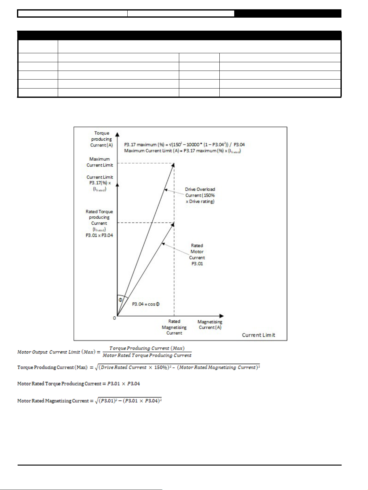
Safety information Electrical installation Drive Parameters
Parameter
Short
description
Minimum
Default
Typ e
Display Format
Coding RW, VM, RA, BU
Defines the maximum torque producing current that can be supplied to the motor. It is a symmetrical limit which means that it is applied when the
motor is motoring or regenerating.
The maximum setting for this parameter is defined by the setting of Motor Rated Current (P3.01) and Motor Rated Power Factor (P3.04). The
maximum setting can be calculated from the diagram as below:
P3.17 Motor Output Current Limit
Defines the maximum torque producing current the drive will deliver to the motor
0.0
171.0
16 Bit User Save
Standard
Maximum
Units
Update Rate
Decimal Places
Motor Current Variable
400 ms
1
The default value (165%) is the maximum setting when the Motor Rated Current (P3.01) is equal to the Drive Rated Current, and
the Motor Rated Power Factor (P3.04) is 0.85.
If the Motor Rated Current (P3.01) is lower than the Drive Rated Current, or if Motor Rated Power Factor (P3.04) is lower than
0.85; then Motor Output Current Limit (P3.17) could be increased to provide more torque producing current. This increase is an overload, and as
such the drive will only allow increased current for a short duration to prevent the motor overheating.
If the maximum motor torque should be limited in an application, this parameter should be reduced accordingly.
This value is populated when Perform Auto-tune (P3.09) has been performed and can also be adjusted manually.
50 Commander S100 USer Guide
Page 51
Safety information Electrical installation Drive Parameters
NOTE
Parameter
Short
description
Minimum
Default
Typ e
Display Format
Coding RW
P3.18 Stator Resistance
Defines the resistance of the motor stator
0.00
2.00
16 Bit User Save
Standard
Maximum
Units Ω
Update Rate
Decimal Places
199.99
400 ms
2
This parameter stores the stator resistance of the motor and is used when Motor Control Mode (P3.05) is set to resistance compensation, and
also when Catch An Already Spinning Motor (P3.11) is enabled. This value is populated when Perform Auto-tune (P3.09) has been performed and
can also be adjusted Manually.
Parameter
Short
description
Minimum
Default
Typ e
Display Format
Coding RW
P3.19 Motor Stability Optimiser
This can reduce vibration/oscillation under some load conditions.
0
0
1 Bit User Save
Standard
Maximum
Units
Update Rate
Decimal Places
1
400 ms
0
When this parameter is enabled it alters the motor control algorithm to help reduce stability problems. The disadvantages of setting this parameter
are increased acoustic noise from the motor and a reduction in the thermal capability of the drive at low output frequencies.
This is typically required when lightly loaded motors exhibit stability issues below half rated speed, or when fully loaded motors exhibit instability at
maximum output voltage.
Parameter
Short
description
Minimum
Default
Typ e
Display Format
Coding RW
P3.20 Reverse Motor Direction
Makes the motor run in the opposite direction
0
0
1 Bit User Save
Standard
Maximum
Units
Update Rate
Decimal Places
1
400 ms
0
If the motor direction does not match the required forward and reverse control commands, this parameter will change the motor direction without the
need to swap output cables. Changes to this parameter will only take effect when the drive is not running.
This reverses the output phase sequence for the selected forward and reverse directions which is non-standard.
Commander S100 User Guide 51
Page 52
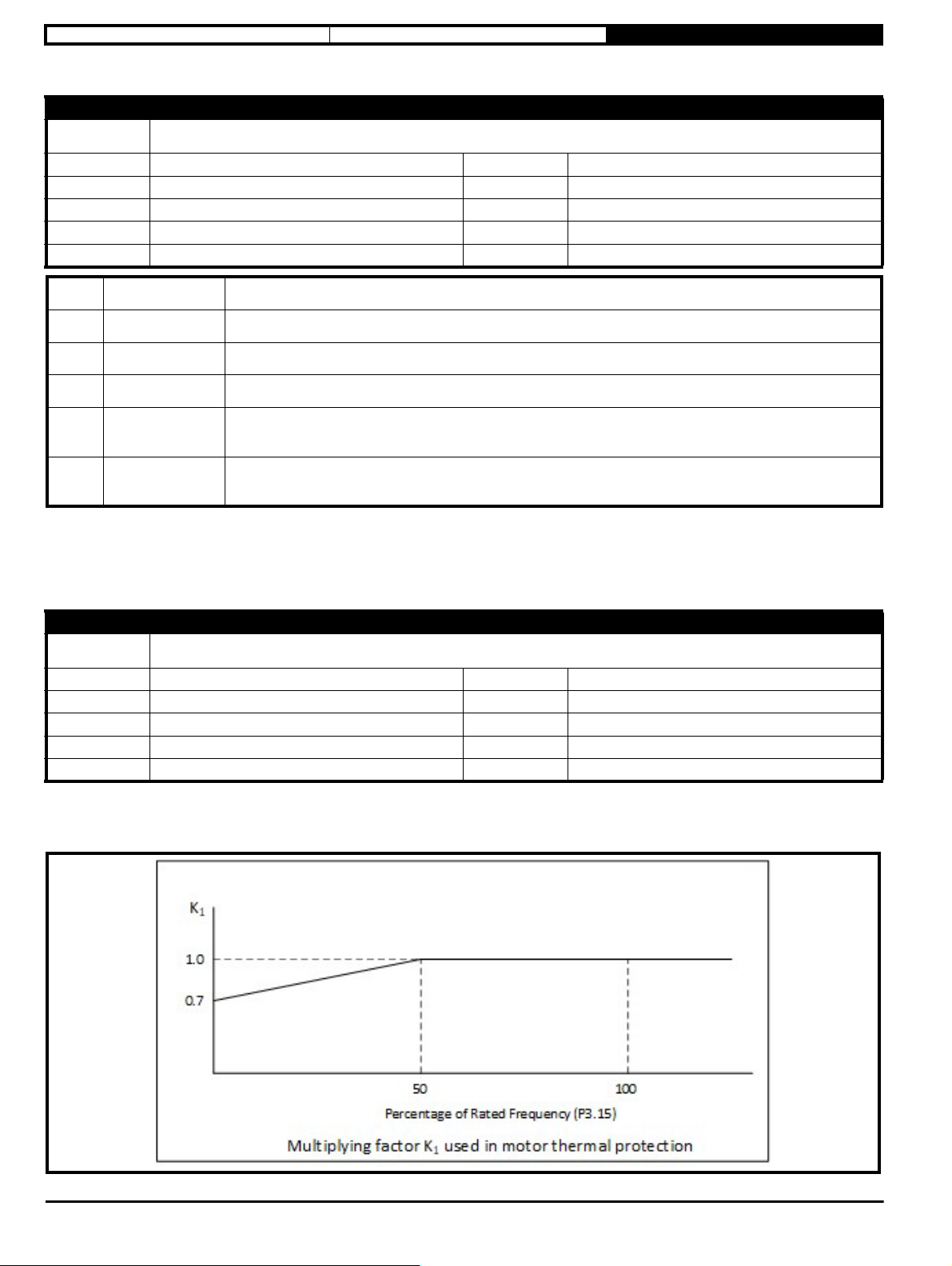
Safety information Electrical installation Drive Parameters
Parameter
Short
description
Minimum
Default
Typ e
Display Format
Coding RW, TE, BU
P3.21 Thermal Protection Action
Set to the required thermal protection operation
0
3
8 Bit User Save
Standard
Maximum
Units
Update Rate
Decimal Places
4
400 ms
0
Value Text Description
0 Disabled No motor thermal protection but drive thermal protection is still active
1 Error with Save Drive generates an Error when Limit reached. Motor and Drive thermal protection percentages are stored at power down
2 Error Drive generates an Error when Limit reached. Motor and Drive thermal protection percentages start at 0% at power up
3Limit with Save
4Limit
Current is limited if drive or motor thermal percentage approaches 100%. Motor and Drive percentages are stored at
power down (default)
Current is limited if drive or motor thermal percentage approaches 100%. Motor and Drive percentages start at 0% at
power up
If the drive or motor is getting too hot the default setting will limit the output current. Change this parameter to configure a different action as detailed
above.
If any of the current limiting modes are selected, the larger of Motor Thermal Percentage (P1.22) and Drive Thermal Percentage (P1.23) is used to
reduce the current limit. If the larger percentage is > 90% the current limit set in Motor Output Current Limit (P3.17) is progressively reduced to 0 as
the percentage increases from 90% to 100%. If thermal limiting is active, bit 2 is set in Drive State (P1.05).
Parameter
Short
description
Minimum
Default
Typ e
Display Format
Coding RW, BU
P3.22 Low Frequency Thermal Protection
Should be set if naturally cooled motor is required to run at high load currents at low frequency
0
1
1 Bit User Save
Standard
Maximum
Units
Update Rate
Decimal Places
1
400 ms
0
If a naturally cooled motor is required to run at high loads at low frequencies then this parameter should be set to On to protect the motor
thermally. Motor Rated Current (P3.01) is multiplied by a factor K
condition. When this parameter is set to Off (0), K
= 1, and when this parameter is set to On (1), K1is as the diagram below.
1
to determine the level above which the motor is considered to be in an overload
1
52 Commander S100 USer Guide
Page 53

Safety information Electrical installation Drive Parameters
Parameter
Short
description
Minimum
Default
Typ e
Display Format
Coding RW, BU
P3.23 Current Controller Gain
Defines the current loop controller gain
0
40
8 Bit User Save
Standard
Maximum
Units
Update Rate
Decimal Places
250
400 ms
0
Used to adjust the gain of the current limit controller. This does not normally need to be adjusted, but can be reduced if there is evidence of motor
noise during current limiting. Increasing the value may be required if Standard Ramp (1) or Standard Ramp Plus Motor (2) are being used
in Deceleration Ramp Type (P2.11) with a high inertia load, or if Supply Loss Action (P4.08) > 0, as the increased gain will help the control of the DC
link voltage during these operations.
Commander S100 User Guide 53
Page 54
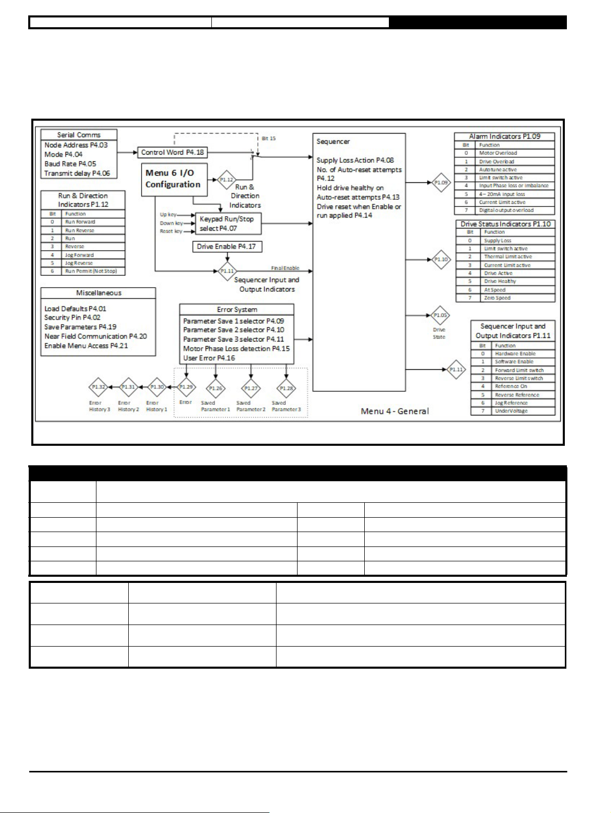
Safety information Electrical installation Drive Parameters
3.10.4 Menu 4 – General
This menu contains parameters related to the general drive settings, communication setup parameters and miscellaneous functions such as defining
parameter values to store when an error occurs.
Associated Parameters
• Parameter 1 Saved Value on Error (P1.26)
• Parameter 2 Saved Value on Error (P1.27)
• Parameter 3 Saved Value on Error (P1.28)
Parameter
Short
description
Minimum
Default
Typ e
Display Format
Coding RW, TE, BU
Value Text Description
0 None No action
1 50Hz Restore Factory Defaults for 50 Hz region
2 60Hz Restore Factory Defaults for 60 Hz region
If this parameter is set to something other than 0 then the drive will load the appropriate defaults and save parameters. This parameter will be reset to
0 after the action is completed. If editing on the keypad the action will be performed when the edit is finished.
After this has been set, it cannot be undone.
P4.01 Restore Factory Defaults
Restore the drive's default parameter settings
0
0
8 Bit Volatile
Standard
Maximum
Units
Update Rate
Decimal Places
2
0
54 Commander S100 USer Guide
Page 55
Safety information Electrical installation Drive Parameters
Parameter
Short
description
Minimum
Default
Typ e
Display Format
Coding RW, BU
P4.02 Security Pin
Defines the user security pin of the drive
0
0
16 Bit User Save
Standard
Maximum
Units
Update Rate
Decimal Places
9999
0
Defines the 4-digit security pin of the drive. This parameter should be set to a value other than 0 to prevent unauthorised write access to the drive.
When a value greater than 0 has been set, it will not be displayed on the keypad or Marshal app to maintain security. If a value has been set, the
security pin must be entered before any parameter can be adjusted via the keypad.
Parameter
Short
description
Minimum
Default
Typ e
Display Format
Coding RW, BU
P4.03 Serial Node Address
Defines the serial address of the drive
1
1
8 Bit User Save
Standard
Maximum
Units
Update Rate
Decimal Places
247
0
Defines the node address for the serial communications interface in the range of 1 to 247.
Parameter
Short
description
Minimum
Default
Typ e
Display Format
Coding RW, TE, BU
P4.04 Serial Mode
Defines the serial mode of the drive
0
0
8 Bit User Save
Standard
Maximum
Units
Update Rate
Decimal Places
3
0
Value Text Description
0 8.2NP 8 data bits, 2 stop bits, no parity bit
1 8.1NP 8 data bits, 1 stop bit, no parity bit
2 8.1EP 8 data bits, 1 stop bit, even parity bit
3 8.1OP 8 data bits, 1 stop bit, odd parity bit
The drive always uses the Modbus RTU protocol and is always a slave.
Commander S100 User Guide 55
Page 56
Safety information Electrical installation Drive Parameters
Parameter
Short
description
Minimum
Default
Typ e
Display Format
Coding RW, TE, BU
Value Text
0 Disabled
1600
2 1200
3 2400
4 4800
5 9600
6 19200
P4.05 Serial Baud Rate
Defines the serial baud rate of the drive
0
0
8 Bit User Save
Standard
Maximum
Units
Update Rate
Decimal Places
10
0
7 38400
8 57600
9 76800
10 115200
Parameter
Short
description
Minimum
Default
Typ e
Display Format
Coding RW, BU
Defines the delay in the drive responding to a message from the host. This may need to be extended if the host is not ready to receive data within
1 ms of the drive receiving a message. This delay is added to the base delay of 1 ms.
P4.06 Minimum Serial Comms Transmit Delay
Defines the minimum delay between the host message being received and the drive response
0
0
8 Bit User Save
Standard
Maximum
Units ms
Update Rate
Decimal Places
250
0
56 Commander S100 USer Guide
Page 57
Safety information Electrical installation Drive Parameters
NOTE
Parameter
Short
description
Minimum
Default
Typ e
Display Format
Coding RW, BU
P4.07 Keypad Run and Stop Function Select
Selects the digital function of the Reset and Up/Down keys on the keypad
0
0
8 Bit User Save
Standard
Maximum
Units
Update Rate
Decimal Places
2
0
Selects the function of the Reset and Up/Down keys for starting and stopping the drive.
Value Description
0 The keypad cannot be used to run and stop the drive
1 Pressing the Up and Down keys together will run the drive and pressing the Stop/Reset key will stop the drive.
2 Continuously pressing the Up and Down keys together will cause the drive to run in the forward direction at the programmed Jog speed.
The value of this parameter can be set by Run/Stop Configuration (P6.13).
Parameter
Short
description
Minimum
Default
Typ e
Display Format
Coding RW, TE, BU
P4.08 Supply Loss Action
Defines the behaviour of the drive when the supply voltage is removed
0
0
8 Bit User Save
Standard
Maximum
Units
Update Rate
Decimal Places
2
0
Value Text Description
0 Disable Operate normally unless the under-voltage condition is detected
1 Ramp Stop
2 Ride Through
Stops with selected deceleration while attempting to control the DC link voltage to take energy
from the motor
Attempts to control the DC link voltage to take energy from the motor and continues normally if the
supply returns
If the supply voltage returns during a Ramp stop or before the drives supply rails have collapsed, the run command needs to be removed and reapplied before the drive will run again.
Commander S100 User Guide 57
Page 58

Safety information Electrical installation Drive Parameters
Parameter
Short
description
Minimum
Default
Typ e
Display Format
Coding RW, TE, BU
Value Text
0 None
1 Output Frequency
2 Output Voltage
3 Output Power
4Motor RPM
5Drive State
6 Output Current
P4.09 Parameter 1 Save on Error Selector
Defines which monitoring parameter is saved on an error
0
3
8 Bit User Save
Standard
Maximum
Units
Update Rate
Decimal Places
25
0
7 Torque Producing Current
8 Percentage Load
9 Alarm Indicators
10 Drive Status Indicators
11 Sequencer Indicators
12 Run and Direction
13 Ramp Input
14 Ramp Output
15 T2 Analog 1 Percentage
16 T4 Analog 2 Percentage
17 T15 Freq. Input %
18 Up/Down Percentage
19 PID Percentage
20 PID Status Indicators
21 PID Error
22 Motor Thermal Percentage
23 Drive Thermal Percentage
24 DC Bus Voltage
25 Digital IO Indicators
58 Commander S100 USer Guide
Page 59

Safety information Electrical installation Drive Parameters
If the drive enters an Error state, it is possible to save several parameter values at the instant of the error. This can be useful to locate the source of
the error. This defines the first of three parameters that can be saved.
The value is saved in Parameter 1 Saved Value on Error (P1.26).
The saved values and error code are maintained after the error has been reset.
Parameter
Short
description
Minimum
Default
Typ e
Display Format
P4.10 Parameter 2 Save on Error Selector
Defines which monitoring parameter is saved on an error
0
4
8 Bit User Save
Standard
Coding RW, TE, BU
See Parameter 1 Save on Error Selector (P4.09).
Parameter
Short
description
Minimum
Default
Typ e
Display Format
P4.11 Parameter 3 Save on Error Selector
Defines which monitoring parameter is saved on an error
0
5
8 Bit User Save
Standard
Coding RW, TE, BU
See Parameter 1 Save on Error Selector (P4.09).
Parameter
Short
description
Minimum
Default
Typ e
Display Format
P4.12 Number of Auto Reset Attempts
Set to the number of required auto-reset attempts
0
0
8 Bit User Save
Standard
Coding RW, TE, BU
Maximum
Units
Update Rate
Decimal Places
Maximum
Units
Update Rate
Decimal Places
Maximum
Units
Update Rate
Decimal Places
25
0
25
0
6
0
Value Text
0 None
1One
2Two
3 Three
4 Four
5Five
6 Continuous
If the drive enters an Error state, it can automatically attempt to reset.
If this parameter is set to 0 then no auto-reset attempts are made. Any other value will cause the drive to automatically reset following an error for the
number of times programmed after a delay of one second. Some errors have extended delays such as motor over current which will reset after ten
seconds. The auto-reset count is only incremented when the error is the same as the previous error otherwise it is reset to zero. When the auto-reset
count reaches the programmed value, any further error of the same value will require a manual reset from the keypad or via serial comms.
If there has been no error for five minutes, then the auto-reset count is cleared. Some errors cannot be automatically reset such as stored HF errors.
When a manual reset is performed the auto-reset counter is reset to zero.
If Number of Auto Reset Attempts (P4.12) = 6 the auto-reset counter is held at zero and so there is no limit on the number of auto-reset attempts.
Commander S100 User Guide 59
Page 60

Safety information Electrical installation Drive Parameters
NOTE
Parameter
Short
description
Minimum
Default
Typ e
Display Format
Coding RW
P4.13 Hold Drive Healthy on Auto Reset Attempts
Set to hold drive healthy if further auto-reset attempts are possible
0
0
1 Bit User Save
Standard
Maximum
Units
Update Rate
Decimal Places
1
0
If this parameter is set to Off (0) then Bit 5 (Healthy) in Drive Status Indicators (P1.10) is cleared every time the drive generates an error regardless of
any auto-reset that may occur. If it is set to On (1) then Bit 5 (Healthy) is not cleared on an error if any further auto-reset attempts are possible.
If the under-voltage state becomes active Bit 5 (Healthy) in Drive Status Indicators (P1.10) is always set to Off (0).
Parameter
Short
description
Minimum
Default
Typ e
Display Format
Coding RW, BU
P4.14 Drive Reset When Enable or Run Applied
Reset an error with application of enable or run
0
1
1 Bit User Save
Standard
Maximum
Units
Update Rate
Decimal Places
1
0
Errors are automatically reset on the application of an enable or run signal. This feature can be disabled by setting this parameter to Off (0).
Parameter
Short
description
Minimum
Default
Typ e
Display Format
Coding RW
P4.15 Motor Phase Loss Detection
Enable motor phase loss detection
0
1
1 Bit User Save
Standard
Maximum
Units
Update Rate
Decimal Places
1
0
Output phase loss detection can be used to detect a disconnected motor phase or a break in the wire between the drive and the motor.
If the motor is running significantly faster than its Motor Rated Speed (P3.02) the phase loss may not be detected. If the motor is very heavily loaded
it is likely to stall before the phase loss is detected.
This feature can be enabled by setting this parameter to On (1).
Parameter
Short
description
Minimum
Default
P4.16 User Error
Defines which user error is to occur
0
0
Maximum
Units
255
Typ e 8 Bit Volatile Update Rate
Display Format
Standard
Coding RW, BU
Decimal Places
0
This parameter is intended for use over communications only and not via the keypad.
An error number can be written to this parameter to generate that error in the drive, or a different (user defined) error if the number written is unused
by the drive. This parameter can also be used to reset errors and clear the error log:
Set to 255 to clear the error history.
Set to 100 to reset the drive.
Setting to 0 will not result in an error.
60 Commander S100 USer Guide
Page 61

Safety information Electrical installation Drive Parameters
Parameter
Short
description
Minimum
Default
P4.17 Drive Enable
Set to On to enable the drive
0
1
Maximum
Units
Typ e 1 Bit User Save Update Rate
Display Format
Standard
Decimal Places
Coding RW, BU
This must be set to On (1) to enable the drive unless Binary Control Word (P4.18) is enabled.
Parameter
Short
description
Minimum
P4.18 Binary Control Word
Controls the sequencer inputs if the control word is enabled
0
(Display: 0000000000000000
Maximum
1
0
65535
(Display: 1111111111111111)
Default
0
(Display: 0000000000000000)
Units
Typ e 16 Bit Volatile Update Rate
Display Format
Binary
Coding RW, BU
Decimal Places
0
If Bit 15 in this parameter is set to zero then the parameter has no effect, but if it is set to one it overrides all of the corresponding inputs to the
sequencer and other digital input functions shown in the table below. Once the control word has been enabled, it must continue to be written to at
least once a second to prevent a Watchdog error (Error 30) from being generated. Disabling the control word returns the drive to terminal control and
the parameter no longer needs to be refreshed to prevent the watchdog error.
Should only be used by serial communications.
Bit Function Description
Bit 0 Software Enable Set to 1 to enable the drive
Bit 1 Run Forward Set to 1 to run forwards
Bit 2 Jog Forward Set to 1 to jog forwards
Bit 3 Run Reverse Set to 1 to run in the reverse direction
Bit 4 Reverse Set to 1 to reverse the direction
Bit 5 Run Set to 1 to run
Bit 6 Run Permit (Not Stop) Set to 1 to enable latching which will be cleared when set to 0
Bit 7 Reference Selector 0 Used to select which reference is used by the reference system
Commander S100 User Guide 61
Page 62

Safety information Electrical installation Drive Parameters
Bit 8 Reference Selector 1 Used to select which reference is used by the reference system
Bit 9 Jog Reverse Set to 1 to jog in the reverse direction
Bit 10 Ramp Rate Selector Used to select which ramp rates are used by the ramp system
Bit 11 Reserved Not used by the drive
Bit 12 Initiate Error Set to 1 to repeatedly initiate the control word error
Bit 13 Reset Drive Set to 1 to reset the drive, clearing errors. This is automatically cleared
Bit 14 Reserved Not used by the drive
Bit 15 Enable Control Word Set to 1 to enable the binary control word
Parameter
Short
description
Minimum
Default
Typ e 1 Bit Volatile Update Rate
Display Format
Coding RW
If this parameter is set to On (1) then a full save will be initiated. When the save is complete the parameter will be automatically reset to Off (0).
Should only be used by serial communications because a any parameter changes made by the keypad are automatically saved upon exiting the
parameter
Parameter
Short
description
Minimum
Default
Typ e 8 Bit User Save Update Rate
Display Format
Coding RW, TE, BU
Value Text Description
P4.19 Save Parameters
Set to 1 to save parameters
0
0
Standard
P4.20 Near Field Communication (NFC)
NFC Control
0
2
Standard
Maximum
Units
Decimal Places
Maximum
Units
Decimal Places
1
0
2
0
0 Disabled NFC communications are blocked
1 Read Only
2 Read & Write The drive's NFC features are fully enabled
The drive's NFC can be read offline by the app, and while on
drive configuration files and parameters can be read
62 Commander S100 USer Guide
Page 63

Safety information Electrical installation Drive Parameters
3.10.5 Menu 5 – PID Controller
The PID controller is suitable for use in applications requiring basic closed-loop control of a system or process.
Associated Parameters
• PID Percentage (P1.19)
• PID Status Indicators (P1.20)
• PID Error (P1.21)
• Reference Select 1 (P2.21)
• T2 Analog Input 1 Type (P6.01)
• T11 Digital Input 1 Function Select (P6.16)
Parameter
Short
description
Minimum
Default
Typ e 16 Bit User Save Update Rate
Display Format
Coding RW
Used where a set point for the controller is fixed and does not change or could be updated via serial communications.
P5.01 PID Fixed Reference Set-Point 1
Defines the value of fixed reference set point 1 for the PID controller
-100.00
0.00
Standard
Maximum
Units %
Decimal Places
100.00
2
Commander S100 User Guide 63
Page 64
Safety information Electrical installation Drive Parameters
NOTE
Parameter
Short
description
Minimum
Default
P5.02 PID Fixed Reference Set-Point 2
Defines the value of fixed reference set point 2 for the PID controller
-100.00
0.00
Maximum
Units %
100.00
Typ e 16 Bit User Save Update Rate
Display Format
Standard
Coding RW
Decimal Places
2
Used where a set point for the controller is fixed and does not change or could be updated via serial communications.
Parameter
Short
description
Minimum
Default
P5.03 PID Reference Selector
Defines the input source for the reference of the PID controller
0
6
Maximum
Units
6
Typ e 8 Bit User Save Update Rate
Display Format
Standard
Coding RW, TE, BU
Decimal Places
0
Value Text Description
0 None Fixed value of 0%
1 Analog 1 Percent Scaled value of analog input 1
2 Analog 2 Percent Scaled value of analog input 2
3 Frequency Input % Scaled value of the frequency input
4 Up/Down Percent Reference set by the Up/Down control
5 Fixed Reference 1 Fixed reference Set-Point 1 (P5.01)
6 Fixed Reference 2 Fixed reference Set-Point 2 (P5.02)
The value of this parameter can be set by Frequency Reference Configuration (P2.03).
Parameter
Short
description
Minimum
Default
P5.04 PID Feedback Selector
Defines the input source for the feedback of the PID controller
0
0
Maximum
Units
3
Typ e 8 Bit User Save Update Rate
Display Format
Standard
Coding RW, TE, BU
Decimal Places
0
Value Text Description
0 None Fixed value of 0%
1 Analog 1 Percent Scaled value of analog input 1
2 Analog 2 Percent Scaled value of analog input 2
3 Frequency Input % Scaled value of the frequency input
64 Commander S100 USer Guide
Page 65
Safety information Electrical installation Drive Parameters
NOTE
Parameter
Short
description
Minimum
Default
P5.05 PID Feed Forward Selector
Defines the input source for the feed-forward reference of the PID controller
0
0
Maximum
Units
6
Typ e 8 Bit User Save Update Rate
Display Format
Standard
Coding RW, TE, BU
Decimal Places
0
Value Text Description
0 None Fixed value of 0%
1 Analog 1 Percent Scaled value of analog input 1
2 Analog 2 Percent Scaled value of analog input 2
3 Frequency Input % Scaled value of the frequency input
4 Up/Down Percent Reference set by the Up/Down control
5 Fixed Reference 1 Fixed reference Set-Point 1 (P5.01)
6 Fixed Reference 2 Fixed reference Set-Point 2 (P5.02)
The PID can be used to provide a speed reference for the drive directly, or to provide a trim which is used to adjust a reference provided for the drive.
This parameter selects the source of the input to be trimmed.
If this parameter is set to zero, PID Percent is given by:
PID Percentage (P1.19) = PID Error (P1.21) * [ PID Proportional Gain (P5.07) + PID Integral Gain (P5.08) / s ]
If an input has been selected as a feed Forward term, PID Percent is given by:
PID Percentage (P1.19) = PID Error (P1.21) * [ PID Proportional Gain (P5.07) + PID Integral Gain (P5.08) / s ] + Feed Forward Source
The PID integrator is held when the PID output reaches 100 %.
The value of this parameter can be set by Frequency Reference Configuration (P2.03).
Parameter
Short
description
Minimum
Default
P5.06 PID Reference Slew Rate Limit
Defines the maximum rate of change of the reference to the PID controller
0.0
0.0
Maximum
Units s
3200.0
Typ e 16 Bit User Save Update Rate
Display Format
Standard
Coding RW, BU
Decimal Places
1
The time entered is the time for the reference to change from 0 to 100%. If using high PID gains, this parameter can be used to reduce over-shoot of
a large step change in the PID reference.
Parameter
Short
description
Minimum
Default
P5.07 PID Proportional Gain
Defines the Kp gain used for the PID controller
0.000
1.000
Maximum
Units
4.000
Typ e 16 Bit User Save Update Rate
Display Format
Standard
Coding RW, BU
Decimal Places
3
This value is multiplied with the PID Error (P1.21).
If PID Error (P1.21) = 10%, the proportional term is a value of 10% if this parameter is set to 1.000.
A higher value will reduce response time. However, if the value is set too high it may introduce oscillation in the system.
Commander S100 User Guide 65
Page 66
Safety information Electrical installation Drive Parameters
Parameter
Short
description
Minimum
Default
Typ e 16 Bit User Save Update Rate
Display Format
Coding RW, BU
The PID integral gain increases the PID Percentage (P1.19) at an increasing rate.
This value is multiplied by the PID Error (P1.21) and the result added to the PID Output Percentage.
Setting a value of 0 disables the integral gain. Setting an integral value will remove any steady state error.
For a PID error = 100% and this parameter set to 0.5, then the integral term increases linearly by 50% per second.
Parameter
Short
description
Minimum
Default
Typ e 16 Bit User Save Update Rate
Display Format
Coding RW
The output of the PID controller is limited to this level. If the limit is reached Bit 1 in PID Status Indicators (P1.20) is set and the Integrator is prevented
from decreasing further.
P5.08 PID Integral Gain
Defines the Ki gain used for the PID controller
0.000
0.500
Standard
P5.09 PID Output Lower Limit
Defines the minimum value of the output for the PID controller
-100.00
0.00
Standard
Maximum
Units
Decimal Places
Maximum
Units %
Decimal Places
4.000
3
100.00
2
Parameter
Short
description
Minimum
Default
Typ e 16 Bit User Save Update Rate
Display Format
Coding RW, BU
The output of the PID controller is limited to this level. If the limit is reached Bit 1 in PID Status Indicators (P1.20) is set and the integrator is prevented
from increasing further.
P5.10 PID Output Upper Limit
Defines the maximum value of the output for the PID controller
0.00
100.00
Standard
Maximum
Units %
Decimal Places
100.00
2
66 Commander S100 USer Guide
Page 67
Safety information Electrical installation Drive Parameters
NOTE
Parameter
Short
description
Minimum
Default
P5.11 PID Enable Selector
Selects an internal condition that can be used to enable the PID controller
0
0
Maximum
Units %
11
Typ e 8 Bit User Save Update Rate
Display Format
Standard
Coding RW, TE, BU
Decimal Places
0
Value Text Description
0 None Off (No function selected)
1 Drive Running On if the drive is running
2 At Speed On if the output speed is within 1Hz of the reference
3 At Zero On if the output is at 0Hz +/- 2Hz
4 Under Voltage On if the drive is in the under-voltage state
5 External Error On if the external error input has been set
6 Drive Ready On if the drive is ready
7 Drive Healthy On if the drive is healthy
8 Current Limit Active On if the drive is limiting the output current
9 Reverse Selected On if the reverse direction has been selected
10 An In Current Loss On if an analog input current loss has been detected
11 Threshold Detector On if the threshold detector is active
If it is required that an internal condition should be used to enable the PID, this parameter should be set to the required condition. For example, if it is
required that the Threshold Detector should enable the PID, this parameter should be set to 11.
Enabling the PID is dependent on two conditions, the value set in this parameter and the digital input function PID Hardware Enable (13) as per the
truth table below.
PIDEnableSelector
Function
PIDHardwareEnable(13) PIDEnabled
None Not Configured Yes
None 0 No
None 1 Yes
0 Not Configured No
00 No
01 No
1 Not Configured Yes
10 No
11 Yes
Bit 0 in PID Status Indicators (P1.20) indicates whether the PID is enabled or not.
The value of this parameter can be set by Frequency Reference Configuration (P2.03).
Commander S100 User Guide 67
Page 68
Safety information Electrical installation Drive Parameters
Parameter
Short
description
Minimum
Default
Typ e 8 Bit User Save Update Rate
Display Format
Coding RW, TE, BU
Value Text Description
0 None 0%
1 Ramp Input The drive frequency reference before the ramps
2 Ramp Output The drive frequency reference after the ramp has been applied
3 Output Frequency The output frequency of the drive
4 Output Current The magnitude of the output current
5 Torque Prod Current The torque producing output current
6 Output Voltage The output voltage
7 DC Bus Voltage The DC bus voltage
8 Analog 1 Percentage The value of analog 1 percentage
9 Analog 2 Percentage The value of analog 2 percentage
P5.12 Threshold Detector Selector
Defines the analog source for the threshold detector
0
0
Standard
Maximum
Units
Decimal Places
15
0
10 Freq. input Percent The value of the frequency input percentage
11 Output Power The output power
12 Motor RPM The motor RPM
13 Percentage Load The percentage load
14 PID Percentage The percentage output of the PID controller
15 PID Error The error of the PID controller
An automatic scaling takes place when parameters are selected as a threshold source. The maximum value of the parameter is used as the full scale
value such that the threshold input will be at 100% when the parameter value is at its maximum.
Parameter
Short
description
Minimum
Default
Typ e 16 Bit User Save Update Rate
Display Format
Coding RW, BU
PID Enable Selector (P5.11) Behaviour
Source < Lower Threshold Off
Lower Threshold ≤ Source < Upper Threshold No change of state
Source ≥ Upper Threshold On
P5.13 Threshold Detector Level
Defines the level for the threshold detector
0.00
0.00
Standard
Maximum
Units %
Decimal Places
100.00
4 ms
2
Lower Threshold = Threshold Detector Level (P5.13) - (Threshold Detector Hysteresis (P5.14) / 2)
Upper Threshold = Threshold Detector Level (P5.13) + (Threshold Detector Hysteresis (P5.14) / 2)
The behaviour can then be delayed with Threshold Detector Delay (P5.15), and inverted with Threshold Detector Output Invert (P5.16).
The Threshold Detector output is shown in bit 2 of PID Status Indicators (P1.20).
68 Commander S100 USer Guide
Page 69
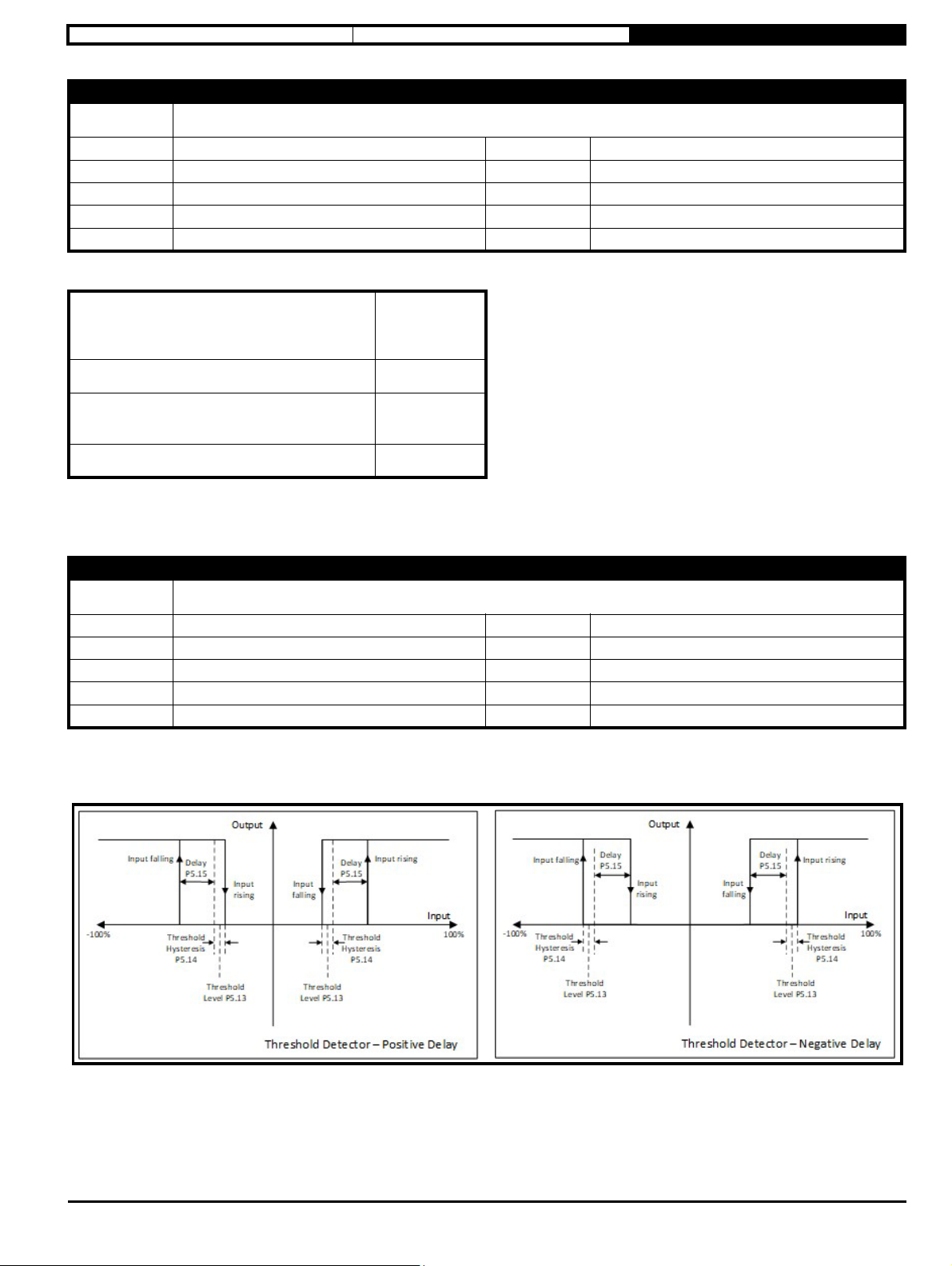
Safety information Electrical installation Drive Parameters
Parameter
Short
description
Minimum
Default
P5.14 Threshold Detector Hysteresis
Defines the hysteresis for the threshold detector
0.00
0.00
Maximum
Units %
25.00
Typ e 16 Bit User Save Update Rate
Display Format
Standard
Coding RW, BU
Decimal Places
2
The hysteresis behaviour and levels are described below.
Select source
(Threshold Detector Selector (P5.12)) after
scaling
Output before
delay applied
Source < Lower Threshold Off
Lower Threshold ≤ Source < Upper Threshold
No change of
state
Source ≥ Upper Threshold On
Lower Threshold = Threshold Detector Level (P5.13) - (Threshold Detector Hysteresis (P5.14) / 2)
Upper Threshold = Threshold Detector Level (P5.13) + (Threshold Detector Hysteresis (P5.14) / 2)
Parameter
Short
description
Minimum
Default
P5.15 Threshold Detector Delay
Set to the required time to delay the rising or falling edge of the detector output
-25.0
0.0
Maximum
Units s
25.0
Typ e 16 Bit User Save Update Rate
Display Format
Standard
Coding RW
Decimal Places
1
If this parameter is set to a positive value, then the output does not become On (1) until the input has been above the threshold for the programmed
time. If it has been set to a negative value, then the output remains On (1) until the input has been below the threshold for the programmed time.
See Threshold Detector Level (P5.13) for more information.
See below:
Commander S100 User Guide 69
Page 70
Safety information Electrical installation Drive Parameters
Parameter
Short
description
Minimum
Default
Typ e 1 Bit User Save Update Rate
Display Format
Coding RW
This inverts the logic level from the Threshold Detector.
The Threshold Detector output is shown in bit 2 of PID Status Indicators (P1.20).
Parameter
Short
description
Minimum
Default
Typ e 8 Bit User Save Update Rate
Display Format
Coding RW, TE, BU
Value Text Description
0 None No Digital Function
P5.16 Threshold Detector Output Invert
Set to 1 to invert the output of the threshold detector
0
0
Standard
P5.17 Threshold Detector Function Select
Selects the function of the threshold detector output
0
0
Standard
Maximum
Units
Decimal Places
Maximum
Units
Decimal Places
1
0
19
0
1 Hardware Enable Allows the drive to come out of the inhibit state
2 Run Forward Commands the drive to run forwards
3 Run Reverse Commands the drive to run reverse
4 Run Permit (/Stop)
5 Forward Limit Switch Prevents a run in the forwards direction
6 Reverse Limit Switch Prevents a run in the reverse direction
7 Up/Down % Increase Increases the Up/Down percentage
8 Up/Down % Decrease Decreases the Up/Down percentage
9 Up/Down % Reset Resets the Up/Down percentage
10 Ref Select Bit 0 Used to select Reference 1, 2, 3 or 4 using I/O
11 Ref Select Bit 1 Used to select Reference 1, 2, 3 or 4 using I/O
12 Ramp Select Used to select Acceleration and Deceleration Rate 1 or 2 using I/O
13 PID Hardware Enable
14 External Error Used to generate an Error from an external condition
15 Drive Reset Used to reset the drive from and Error condition
16 Run Commands the drive to run
Permits a Run command when set, resets any run latch when clear (enables latching when
selected as a function)
Enables and disables the PID controller. If no Hardware Enable is required, this configuration
should not be selected
17 Reverse Reverses the direction
18 Jog Forward Jogs forwards
19 Jog Reverse Jogs reverse
Selects the function of the threshold detector. If the threshold detector is required to enable the PID then this parameter is not used
as PID Enable Selector (P5.11) is used to select the detector output.
70 Commander S100 USer Guide
Page 71

Safety information Electrical installation Drive Parameters
Parameter
Short
description
Minimum
Default
P5.17 Threshold Detector Function Select
Selects the function of the threshold detector output
0
0
Maximum
Units
19
Typ e 8 Bit User Save Update Rate
Display Format
Standard
Coding RW, TE, BU
Decimal Places
0
Setting this parameter to On (1) allows PID Percentage (P1.19) to be negative which will cause the motor to rotate in the reverse direction.
Commander S100 User Guide 71
Page 72

Safety information Electrical installation Drive Parameters
NOTE
NOTE
3.10.6 Menu 6 – IO Configuration
This menu contains parameters related to the setup of the drive’s inputs and outputs. To use an analog input or frequency input as a drive reference,
the appropriate value should be set in a Frequency Reference Selector parameter (P2.21 – P2.24).
Associated Parameters
• Sequencer Inputs and Outputs (P1.11)
• Run & Direction Indicators (P1.12)
• T2 Analog Input 1 Percentage (P1.15)
• T4 Analog Input 2 Percentage (P1.16)
• T15 Frequency Input 1 Percentage (P1.17)
• Digital IO Indicators (P1.25)
• Frequency Reference 1 Selector (P2.21)
Parameter
Short
description
Minimum
Default
P6.01 T2 Analog Input 1 Type
Defines the type of input, voltage or current
0
2
Maximum
Units
5
Typ e 8 Bit User Save Update Rate
Display Format
Standard
Coding RW, TE, BU
Decimal Places
0
Value Text Description
0 0-10V A voltage input where 0 V is 0% and 10 V is 100%
1 0-20mA A current input where 0 mA is 0% and 20 mA is 100%
2 4-20mA A current input where 4 mA is 0% and 20 mA is 100%
3 4-20mA Hold A current input where 4 mA is 0% and 20 mA is 100%. The value is held if current < 3 mA
4 4-20mA Stop A current input where 4 mA is 0% and 20 mA is 100%. The drive will stop if current < 3 mA and not restart
5 4-20mA Error A current input where 4 mA is 0% and 20 mA is 100%. An error is generated if current < 3 mA
The analog inputs can be set up as voltage or a current type as defined above. They can also be used as digital inputs where the switching thresholds
are at 70% and 80% for a voltage input and 45% and 55% for a current input. Using an analog input as a digital input does not prevent the analog
function from being used, its digital operation is in addition to the normal analog function. When used as a digital input the terminal does not sink or
source current and so if the input is not being driven an appropriate pull up or pull down must be fitted externally. The resolution of the conversion is
11 bits.
In 4-20mA current input modes a current input less than 3 mA is detected as a current loop loss.
It is not recommended that the input is used as a digital input if 4-20 mA Hold (3) is selected because the input will not change if the current loop is
lost.
The value of this parameter can be set by Frequency Reference Configuration (P2.03).
To avoid the scenario where a wire break occurs, meaning controller loses control of the reference, the analog input should be configured as a 4-20
mA type.
Parameter
Short
description
Minimum
Default
P6.02 T4 Analog Input 2 Type
Defines the type of input, voltage or current
0
0
Maximum
Units
5
Typ e 8 Bit User Save Update Rate
Display Format
Standard
Coding RW, TE, BU
Decimal Places
0
See T2 Analog Input 1 Type (P6.01).
72 Commander S100 USer Guide
Page 73
Safety information Electrical installation Drive Parameters
NOTE
Parameter
Short
description
Minimum
Default
P6.03 T6 Analog Output Type
Defines the type of output, voltage or a current type
0
0
Maximum
Units
2
Typ e 8 Bit User Save Update Rate
Display Format
Standard
Coding RW, TE, BU
Decimal Places
0
Value Text Description
0 0-10V A voltage output where 0% is 0 V and 100% is 10 V
1 0-20mA A current output where 0% is 0 mA and 100% is 20 mA
2 4-20mA A current output where 0% is 4 mA and 100% is 20 mA
The analog output can be set up as voltage or a current type as defined above. For each type, the minimum output is equivalent to a zero value of the
output variable, and the maximum output is equivalent to the maximum value of the output variable. This can be changed
using T6 Analog Output Scaling (P6.07).
Parameter
Short
description
Minimum
Default
P6.04 T11 Digital IO 1 Type
Defines the digital I/O type
0
0
Maximum
Units
4
Typ e 8 Bit User Save Update Rate
Display Format
Standard
Coding RW, TE, BU
Decimal Places
0
Value Text Description
0 Digital Input The low level input must be < 9 V and the high level input > 10 V
1 Digital Output Positive logic digital output
2 Frequency Output A frequency output between 0 Hz and 10 kHz
3 PWM Output A PWM output running at 1 kHz
4 Digital Out Inverted Positive logic digital output with the selected function inverted
Defines the digital IO type for digital I/O 1.
As a Digital Output, the maximum source current is 50 mA (but 100 mA total limit on digital output and 24 V output), and there is a6 - 7 kΩ internal
pull down resistor to 0 V which will sink some current.
As a Frequency Output, 10 kHz is equivalent to the maximum value of the output variable. This can be scaled using T11 Frequency/
PWM Output Scaling (P6.11). The resolution of the frequency output is 12 bit.
As a PWM Output, the output frequency is fixed at 1 kHz and 100% duty is equivalent to the maximum value of the output variable. This can
be changed using T11 Frequency/PWM Output Scaling (P6.11). The resolution of the PWM output is 12 bit. In this mode the output can be
connected to an analog meter for monitoring purposes only as the PWM amplitude only has the accuracy of the 24 V output voltage. The output may
require filtering before connecting to a meter if the meter used is not responsive enough to pick up the 1 kHz output frequency.
The value of this parameter can be set by Frequency Reference Configuration (P2.03).
Commander S100 User Guide 73
Page 74

Safety information Electrical installation Drive Parameters
NOTE
Parameter
Short
description
Minimum
Default
P6.05 T15 Digital Input 5 Type
Defines the type, digital input or a frequency input
0
0
Maximum
Units
1
Typ e 8 Bit User Save Update Rate
Display Format
Standard
Coding RW, TE
Decimal Places
0
Value Text Description
0 Digital Input The low level input must be < 9 V and the high level input > 10 V
1 Frequency Input Frequency input with a maximum frequency of 100 kHz
Defines the input type for digital input 5.
The frequency input can be scaled, limited and inverted using the associated scaling parameters as described by T15 Frequency Input Minimum
Input (P6.29).
The value of this parameter can be set by Frequency Reference Configuration (P2.03).
Parameter
Short
description
Minimum
Default
P6.06 T6 Analog Output Function Select
Selects the parameter that the analog output should represent
0
2
Maximum
Units
17
Typ e 8 Bit User Save Update Rate
Display Format
Standard
Coding RW, TE, BU
Decimal Places
0
Value Text Description
0 None 0%
1 Ramp Input The drive frequency reference before the ramps
2 Ramp Output The drive frequency reference after the ramp has been applied
3 Output Frequency The output frequency of the drive
4 Output Current The magnitude of the output current
5 Torque Prod Current The torque producing output current
6 Output Voltage The output voltage
7 DC Bus Voltage The DC bus voltage
8 Analog 1 Percentage The value of analog 1 percentage
9 Analog 2 Percentage The value of analog 2 percentage
10 Freq. input Percent The value of the frequency input percentage
11 Output Power The output power
12 Motor RPM The motor RPM
13 Percentage Load The percentage load
14 PID Percentage The percentage output of the PID controller
15 PID Error The error of the PID controller
16 Motor Thermal % The thermal percentage to error level of the motor
17 Drive Thermal % The thermal percentage to error level of the drive
Selects the parameter that the analog output should represent. The absolute of the chosen parameter is scaled such that 10 V or 20 mA is equivalent
to the parameter's maximum value. It can be further scaled by T6 Analog Output Scaling (P6.07).
74 Commander S100 USer Guide
Page 75

Safety information Electrical installation Drive Parameters
Parameter
Short
description
Minimum
Default
P6.07 T6 Analog Output Scaling
Defines the scaling factor for the analog output
0.000
1.000
Maximum
Units
40.000
Typ e 16 Bit User Save Update Rate
Display Format
Standard
Coding RW, BU
Decimal Places
3
Defines the scaling factor for the analog output.
An automatic scaling takes place when parameters are selected for an analog output. The maximum value of the parameter is used as the full scale
value such that the analog output will be at full scale when the parameter value is at its maximum value. Some parameters do not reach their
maximum values and so this parameter is provided for the user to apply further scaling and configure a bigger range of the analog output to be used.
If a scale set here causes the output to exceed 100%, the output value is limited to 10 V or 20 mA.
Parameter
Short
description
Minimum
Default
P6.08 T41-T43 Relay Function Select
Selects the drive state that controls the relay output
0
7
Maximum
Units
11
Typ e 8 Bit User Save Update Rate
Display Format
Standard
Coding RW, TE, BU
Decimal Places
0
Value Text Description
0 None Off (No function selected)
1 Drive Active Running On if the drive is running
2 At Speed On if the output speed is within 1Hz of the reference
3 At Zero On if the output is at 0Hz +/- 2Hz
4 Under Voltage On if the drive is in the under-voltage state
5 External Error On if the external error input has been set
6 Drive Ready On if the drive is ready
7 Drive Healthy On if the drive is healthy
8 Current Limit Active On if the drive is limiting the output current
9 Reverse Selected On if the reverse direction has been selected
10 Analog Input Current Loss On if an analog input current loss has been detected
11 Threshold Detector On if the threshold detector is active
Selects the drive function state that controls the relay.
The relay has 3 terminals; normally open (T41), common (T42), and normally closed (T43).
If the function selected is at 0, the common is connected to the normally closed terminal. When the function selected is at 1, common is connected to
the normally open terminal.
Commander S100 User Guide 75
Page 76

Safety information Electrical installation Drive Parameters
NOTE
Parameter
Short
description
Minimum
Default
P6.09 T11 Digital Output 1 Function Select
Selects the drive state that controls the output
0
0
Maximum
Units
11
Typ e 8 Bit User Save Update Rate
Display Format
Standard
Coding RW, TE, BU
Decimal Places
0
Selects the drive state that is indicated by Digital Output 1. The state is inverted if T11 Digital IO 1 Type (P6.04) is set to Digital Output Inverted (4).
See T41-T43 Relay Function Select (P6.08) for output options.
T11 Digital IO 1 Type (P6.04) must be set to Digital Output (1) or Digital Output Inverted (4) for this parameter to have any effect.
Parameter
Short
description
Minimum
Default
P6.10 T11 Frequency/PWM Output Function Select
Selects the parameter that is represented by the output frequency or PWM duty cycle when Digital I/O 1 is in one of these
modes
0
0
Maximum
Units
17
Typ e 8 Bit User Save Update Rate
Display Format
Standard
Coding RW, TE, BU
Decimal Places
0
Selects the parameter that Digital Output 1 should represent in Frequency or PWM output modes. The absolute of the chosen parameter is scaled
such that Maximum output is equivalent to the parameter's maximum value. It can be further scaled by T11 Frequency/PWM Output Scaling (P6.11).
See T11DigitalIO1Type(P6.04) for setting up the output type.
See T6 Analog Output Function Select (P6.06) for output options.
Parameter
Short
description
Minimum
Default
P6.11 T11 Frequency/PWM Output Scaling
Defines the scaling factor applied to the frequency or PWM output
0.000
1.000
Maximum
Units
40.000
Typ e 16 Bit User Save Update Rate
Display Format
Standard
Coding RW, BU
Decimal Places
3
Defines the scaling factor for Digital Output 1 in Frequency (2) and PWM (3) modes.
An automatic scaling takes place when parameters are selected for this output. The maximum value of the parameter is used as the full scale value
such that the output will be at full scale when the parameter value is at its maximum value. Some parameters do not reach their maximum values and
so this parameter is provided for the user to apply further scaling and configure a bigger range of the Frequency or PWM outputs to be used.
Parameter
Short
description
Minimum
Default
P6.12 Negative Logic (NPN Sensor) Select
Set to 1 to enable negative logic (NPN Sensor)
0
0
Maximum
Units
1
Typ e 1 Bit User Save Update Rate
Display Format
Standard
Coding RW
Decimal Places
0
As default the digital inputs are Positive Logic inputs (sinking inputs) to suit PNP sensors. This parameter allows the digital inputs to be set to
Negative Logic inputs (sourcing inputs) to suit NPN type sensors. When analog inputs are also used as digital inputs, they do not source or sink
current, but the logic is inverted when this parameter is set. This parameter has no effect on the digital output or analog inputs.
76 Commander S100 USer Guide
Page 77

Safety information Electrical installation Drive Parameters
Parameter
Short
description
Minimum
Default
P6.13 Run/Stop Configuration
Defines how the digital inputs or keypad are used to run and stop the drive
0
0
Maximum
Units
10
Typ e 8 Bit User Save Update Rate
Display Format
Standard
Coding RW, TE, BU
Decimal Places
0
Value Text Description
0 Custom Parameters have been changed from a standard configuration
1 Enable + Run Forward +Run Reverse Enable on T12, Run Forward on T13, Run Reverse on T14
2 Run Forward + Run Reverse (3 wire) Run Permit on T12, Run Forward on T13, Run Reverse on T14
3 Enable + Run + Reverse Enable on T12, Run on T13, Reverse on T14
4 Run + Reverse Run Permit on T12, Run on T13, Reverse on T14
5 Run + Jog Run Permit on T12, Run on T13, Jog Forward on T14
6 Run Forward + Run Reverse Run Forward on T13, Run Reverse on T14
7 Run + Reverse Run on T13, Reverse on T14
8 Keypad Press Up and Down keys together to run and Reset/Stop key to stop
9 Keypad with Enable
Enable on T12 then Press Up and Down keys together to run and press the
Reset/Stop key to stop.
10 Keypad Jog Hold the Up and Down keys together to jog the motor forwards
This parameter allows quick setup of digital inputs 2 - 4 to control the hardware enable, run, direction and jog commands according to pre-defined
configurations; as well as configuring the drive's keypad for run and stop control.
The assignments are made and saved after the configuration parameter has been edited. Anything marked as "Not Changed" is left at its current
value. If a parameter in the table below is changed after it has been set here, this parameter is automatically set to Custom (0). If the configuration is
set to Custom (0), then no assignments are made so input functions would have to be set manually.
T12 Digital Input 2
Value Configuration
Function Select
(P6.17)
0 Custom Not Changed Not Changed Not Changed Not Changed
1 Enable + Run Forward +Run 1 (Hardware Enable) 2 (Run Forward) 3 (Run Reverse) 0 (Disabled)
2 Run Forward + Run Reverse (3 wire) 4 (Run Permit) 2 (Run Forward) 3 (Run Reverse) 0 (Disabled)
3 Enable + Run + Reverse 1 (Hardware Enable) 16 (Run) 17 (Reverse) 0 (Disabled)
4 Run + Reverse 4 (Run Permit) 16 (Run) 17 (Reverse) 0 (Disabled)
5 Run + Jog 4 (Run Permit) 16 (Run) 18 (Jog Forward) 0 (Disabled)
6 Run Forward + Run Reverse 0 (None) 2 (Run Forward) 3 (Run Reverse) 0 (Disabled)
T13 Digital Input
3 Function Select
(P6.18)
T14 Digital Input
4 Function Selec
t (P6.19)
Keypad Run andStop Fu
nction
Select (P4.07)
7 Run + Reverse 0 (None) 16 (Run) 17 (Reverse) 0 (Disabled)
8 Keypad 0 (None) 0 (None) 0 (None) 1 (Run and Stop Enabled)
9 Keypad with Enable 1 (Hardware Enable) 0 (None) 0 (None) 1 (Run and Stop Enabled)
10 Keypad Jog 0 (None) 0 (None) 0 (None) 2 (Keypad Jog Enabled)
Commander S100 User Guide 77
Page 78

Safety information Electrical installation Drive Parameters
78 Commander S100 USer Guide
Page 79

Safety information Electrical installation Drive Parameters
NOTE
NOTE
Parameter
Short
description
Minimum
Default
P6.14 T2 Analog Input 1 Digital Function Select
Selects the digital function of analog input 1
0
0
Maximum
Units
19
Typ e 8 Bit User Save Update Rate
Display Format
Standard
Coding RW, TE, BU
Decimal Places
0
Selects a digital function of Analog Input 1. The terminal does not have to be configured to be used as a dedicated digital input. Using an analog input
as a digital input does not prevent the analog function from being used, its digital operation is in addition to the normal analog function. See T2 Analog
Input 1 Type (P6.01).
See T11 Digital Input 1 Function Select (P6.16) for a list of functions.
When used as a digital input in voltage mode, the input terminal cannot sink or source current. If driven from a PNP sensor (positive logic), a 6k8
resistor should be fitted between T4 and T3; and if driven by a NPN sensor (negative logic), a 6k8 resistor should be connected between T4 and T9.
Parameter
Short
description
Minimum
Default
P6.15 T4 Analog Input 2 Digital Function Select
Selects the digital function of analog input 2
0
0
Maximum
Units
19
Typ e 8 Bit User Save Update Rate
Display Format
Standard
Coding RW, TE, BU
Decimal Places
0
Selects a digital function of Analog Input 2. The terminal does not have to be configured to be used as a dedicated digital input. Using an analog input
as a digital input does not prevent the analog function from being used, its digital operation is in addition to the normal analog function. See T2 Analog
Input 1 Type (P6.01).
See T11 Digital Input 1 Function Select (P6.16) for a list of functions.
When used as a digital input in voltage mode, the input terminal cannot sink or source current. If driven from a PNP sensor (positive logic), a 6k8
resistor should be fitted between T4 and T3; and if driven by a NPN sensor (negative logic), a 6k8 resistor should be connected between T4 and T9.
Commander S100 User Guide 79
Page 80
Safety information Electrical installation Drive Parameters
NOTE
Parameter
Short
description
Minimum
Default
P6.16 T11 Digital Input 1 Function Select
Selects the function of the digital input if it is in digital input mode
0
0
Maximum
Units
19
Typ e 8 Bit User Save Update Rate
Display Format
Standard
Coding RW, TE, BU
Decimal Places
0
Value Text Description
0 None No Digital Function
1 Hardware Enable Allows the drive to come out of the inhibit state
2 Run Forward Commands the drive to run forwards
3 Run Reverse Commands the drive to run reverse
4 Run Permit (/Stop) Permits a Run command when set, resets any run latch when clear (enables latching when selected as a function)
5 Forward Limit Switch Prevents a run in the forwards direction
6 Reverse Limit Switch Prevents a run in the reverse direction
7 Up/Down % Increase Increases the Up/Down percentage
8 Up/Down % Decrease Decreases the Up/Down percentage
9 Up/Down % Reset Resets the Up/Down percentage
10 Ref Sel Bit 0 Used to select Reference 1, 2, 3 or 4 using I/O
11 Ref Sel Bit 1 Used to select Reference 1, 2, 3 or 4 using I/O
12 Ramp Select Used to select Acceleration and Deceleration Rate 1 or 2 using I/O
13 PID Hardware Enable Enables and disables the PID controller. If no Hardware Enable is required, this configuration should not be selected
14 External Error Used to generate an Error from an external condition
15 Drive Reset Used to reset the drive from and Error condition
16 Run Commands the drive to run
17 Reverse Reverses the direction
18 Jog Forward Jogs forwards
19 Jog Reverse Jogs reverse
Selects the function of Digital I/O 1 if T11 Digital IO 1 Type (P6.04) = 0.
Notes on function selection:
Selecting the Run Permit (Not Stop) function (4) automatically enables a latch on the Run inputs (Run Forward, Run Reverse, and Run), see Run &
Direction Indicators (P1.12). Providing the Run Permit input is active, activation of the Run inputs is latched so that a momentary switch can be used
to start the drive. When Run Permit is made inactive (Stop), all latches are cleared and no Run command is accepted.
If Run Forward or Run Reverse is made active, the Reverse function will be ignored i.e. explicate Run Forward and Run Reverse commands override
the direction selection.
A Jog command is only accepted when the drive is not running.
A Run command overrides a Jog command.
The value of this parameter can be set by Frequency Reference Configuration (P2.03).
80 Commander S100 USer Guide
Page 81
Safety information Electrical installation Drive Parameters
NOTE
NOTE
NOTE
NOTE
Parameter
Short
description
Minimum
Default
P6.17 T12 Digital Input 2 Function Select
Selects the function of the digital input
0
1
Maximum
Units
Typ e 8 Bit User Save Update Rate
Display Format
Standard
Decimal Places
Coding RW, TE, BU
Selects the function of Digital Input 2. See T11 Digital Input 1 Function Select (P6.16).
The value of this parameter can be set by Run/Stop Configuration (P6.13).
Parameter
Short
description
Minimum
Default
P6.18 T13 Digital Input 3 Function Select
Selects the function of the digital input
0
2
Maximum
Units
Typ e 8 Bit User Save Update Rate
Display Format
Standard
Decimal Places
Coding RW, TE, BU
Selects the function of Digital Input 3. See T11 Digital Input 1 Function Select (P6.16).
19
0
19
0
The value of this parameter can be set by Run/Stop Configuration (P6.13).
Parameter
Short
description
Minimum
Default
P6.19 T14 Digital Input 4 Function Select
Selects the function of the digital input
0
3
Maximum
Units
19
Typ e 8 Bit User Save Update Rate
Display Format
Standard
Coding RW, TE, BU
Decimal Places
0
Selects the function of Digital Input 4. See T11 Digital Input 1 Function Select (P6.16).
The value of this parameter can be set by Run/Stop Configuration (P6.13).
Parameter
Short
description
Minimum
Default
P6.20 T15 Digital Input 5 Function Select
Selects the function of the digital input if it is in digital input mode
0
10
Maximum
Units
19
Typ e 8 Bit User Save Update Rate
Display Format
Standard
Coding RW, TE, BU
Decimal Places
0
Selects the function of Digital Input 5 when T15 Digital Input 5 Type (P6.05) = 0 (Digital Input). See T11 Digital Input 1 Function Select (P6.16).
The value of this parameter can be set by Run/Stop Configuration (P6.13).
Commander S100 User Guide 81
Page 82
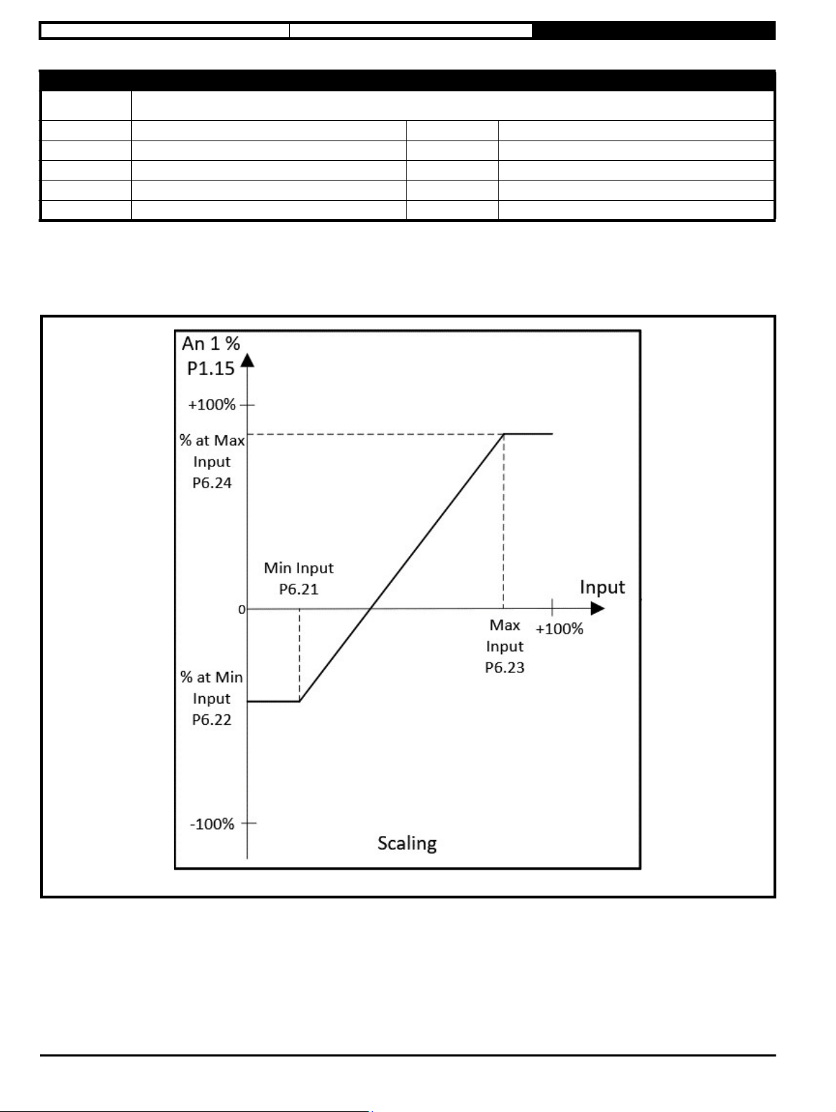
Safety information Electrical installation Drive Parameters
Parameter
Short
description
Minimum
Default
Typ e 16 Bit User Save Update Rate
Display Format
Coding RW
This parameter defines the minimum input level for Analog Input 1 and can be used to limit the range of the measured input.
The used range of the measured input (0 % - 100 %) is defined by two parameters, this parameter being the minimum value used, and T2 Analog
Input 1 Maximum Input (P6.23) being the maximum value used. Changing the default values of these parameters limits the used range of Analog
Input 1. This limited range is then converted to a Percentage input that changes between a level defined for the minimum input with T2 Analog Input
1 Percentage at Minimum Input (P6.22), and a level defined for the maximum input with T2 Analog Input 1 Percentage at Maximum Input (P6.24).
See the diagram below.
P6.21 T2 Analog Input 1 Minimum Input
Defines the minimum value used for analog input 1
0.00
0.00
Standard
Maximum
Units %
Decimal Places
100.00
2
When T2 Analog Input 1 Percentage (P1.15) is used as a motor frequency reference in References & Ramps, there is a conversion from percent to
Hz. See Frequency Reference 1 Selector (P2.21).
This parameter limits the measured input and should be increased if only part of the analog inputs measurable range is to be used. See the example
below which assumes the analog input is set as a voltage type, P6.22 - P6.24 and the Minimum and Maximum Reference Limits are at default values.
Example: If 5 V on the input should equal 0 % of T2 Analog Input 1 Percentage (P1.15), this parameter should be set to 50 %. If the Analog Input is
selected as a reference, 0 V to 5 V would equal a reference of 0 Hz, 6 V would equal a reference of 10 Hz, and 10 V = 50 Hz.
If T2 Analog Input 1 Minimum Input (P6.21) ≥ T2 Analog Input 1 Maximum Input (P6.23) then T2 Analog Input 1 Percentage (P1.15) = 0.00 %
whatever the input level.
82 Commander S100 USer Guide
Page 83
Safety information Electrical installation Drive Parameters
Parameter
Short
description
Minimum
Default
P6.22 T2 Analog Input 1 Percentage at Minimum Input
Defines the value of analog input 1 percentage at minimum input
-100.00
0.00
Maximum
Units %
100.00
Typ e 16 Bit User Save Update Rate
Display Format
Standard
Coding RW
Decimal Places
2
Defines the percentage value at the minimum input level for Analog Input 1 and can be used to scale or invert the measured value.
The used range of the measured input (0 % - 100 %) is defined by two parameters, T2 Analog Input 1 Minimum Input (P6.21) being the minimum
value used, and T2 Analog Input 1 Maximum Input (P6.23) being the maximum value used. Changing the default values of these parameters limits
the used range of Analog Input 1. This limited range is then converted to a Percentage input that changes between a level defined for the minimum
input with this parameter, and a level defined for the maximum input with T2 Analog Input 1 Percentage at Maximum Input (P6.24). See the diagram
in T2 Analog Input 1 Minimum Input (P6.21).
When T2 Analog Input 1 Percentage (P1.15) is used as a motor frequency reference in References & Ramps, there is a conversion from percent to
Hz. See Frequency Reference 1 Selector (P2.21).
See the examples below which assumes the Analog Input is set as a voltage type. P6.21, P6.23, P6.24 and the Minimum and Maximum Reference
Limits are at default values.
Scaling Example: If 0 V on the input should equal 50 % of T2 Analog Input 1 Percentage (P1.15), this parameter should be set to 50 %. If the Analog
Input is selected as a reference, 0 V would equal a reference of 25 Hz, 5 V would equal 37.5 Hz, and 10 V = 50 Hz. (Assuming P6.24 = 100 %)
To invert the input, this parameter should be set larger than T2 Analog Input 1 Percentage at Maximum Input (P6.24).
Invert example: If the input should be inverted, this parameter should be set to 100 %
and T2 Analog Input 1 Percentage at Maximum Input (P6.24) should be set to 0 %. If the Analog Input is selected as a reference, 0 V would equal a
reference of 50 Hz, 5 V would equal a reference of 25 Hz, and 10 V = 0 Hz.
Parameter
Short
description
Minimum
Default
P6.23 T2 Analog Input 1 Maximum Input
Defines the maximum value used for analog input 1
0.00
100.00
Maximum
Units %
100.00
Typ e 16 Bit User Save Update Rate
Display Format
Standard
Coding RW
Decimal Places
2
This parameter defines the maximum input level for Analog Input 1 and can be used to scale the input if a limited range of the analog input level is
available.
The used range of the measured input (0 % - 100 %) is defined by two parameters, this parameter being the maximum value used,
and T2 Analog Input 1 Minimum Input (P6.21) being the minimum value used. Changing the default values of these parameters limits the used range
of Analog Input 1. This limited range is then converted to a Percentage input that changes between a level defined for the minimum
input with T2 Analog Input 1 Percentage at Minimum Input (P6.22), and a level defined for the maximum
input with T2 Analog Input 1 Percentage at Maximum Input (P6.24). See the diagram in T2 Analog Input 1 Minimum Input (P6.21).
When T2 Analog Input 1 Percentage (P1.15) is used as a motor frequency reference in References & Ramps, there is a conversion from percent to
Hz. See Frequency Reference 1 Selector (P2.21).
This parameter limits the measured input and should be decreased if only part of the analog inputs measurable range is to be used. See the example
below which assumes the analog input is set as a voltage type, P6.21, P6.22, P6.24 and the Minimum and Maximum Reference Limits are at default
values.
Example: If 5 V on the input should equal 100 % of T2 Analog Input 1 Percentage (P1.15), this parameter should be set to 50 %. If the Analog Input
is selected as a reference, 0 V would equal a reference of 0 Hz, 2 V would equal a reference of 20 Hz, and 5 V to 10 V would be a reference of 50 Hz.
Commander S100 User Guide 83
Page 84
Safety information Electrical installation Drive Parameters
Parameter
Short
description
Minimum
Default
P6.24 T2 Analog Input 1 Percentage at Maximum Input
Defines the value of analog input 1 percentage reference at maximum input
-100.00
100.00
Maximum
Units %
100.00
Typ e 16 Bit User Save Update Rate
Display Format
Standard
Coding RW
Decimal Places
2
Defines the percentage value at the maximum input level for Analog Input 1 and can be used to scale or invert the measured value.
The used range of the measured input (0 % - 100 %) is defined by two parameters, T2 Analog Input 1 Minimum Input (P6.21) being the minimum
value used, and T2 Analog Input 1 Maximum Input (P6.23) being the maximum value used. Changing the default values of these parameters limits
the used range of Analog Input 1. This limited range is then converted to a Percentage input that changes between a level defined for the minimum
input with T2 Analog Input 1 Percentage at Minimum Input (P6.22), and a level defined for the maximum input with this parameter. See the diagram
in T2 Analog Input 1 Minimum Input (P6.21).
When T2 Analog Input 1 Percentage (P1.15) is used as a motor frequency reference in References & Ramps, there is a conversion from percent to
Hz. See Frequency Reference 1 Selector (P2.21).
See the examples below which assumes the Analog Input is set as a voltage type. P6.21 - P6.23 and the Minimum and Maximum Reference Limits
are at default values.
Scaling Example: If 10 V on the input should equal 50 % of T2 Analog Input 1 Percentage (P1.15), this parameter should be set to 50 %. If the Analog
Input is selected as a reference, 0 V would equal a reference of 0 Hz, 2 V would equal 5 Hz, and 10 V = 25 Hz.
To invert the input, this parameter should be set smaller than T2 Analog Input 1 Percentage at Minimum Input (P6.22).
Invert example: If the input should be inverted, this parameter should be set to 0 %
and T2 Analog Input 1 Percentage at Minimum Input (P6.22) should be set to 100 %. If the Analog Input is selected as a reference, 0 V would equal
a reference of 50 Hz, 5 V would equal a reference of 25 Hz, and 10 V = 0 Hz.
Parameter
Short
description
Minimum
Default
P6.25 T4 Analog Input 2 Minimum Input
Defines the minimum value used for analog input 2
0.00
0.00
Maximum
Units %
100.00
Typ e 16 Bit User Save Update Rate
Display Format
Standard
Coding RW
Decimal Places
2
This parameter defines the minimum input level for Analog Input 2 and can be used to limit the range of the measured input.
See T2 Analog Input 1 Minimum Input (P6.21).
Parameter
Short
description
Minimum
Default
P6.26 T4 Analog Input 2 Percentage at Minimum Input
Defines the value of analog input 2 percentage at minimum input
-100.00
0.00
Maximum
Units %
100.00
Typ e 16 Bit User Save Update Rate
Display Format
Standard
Coding RW
Decimal Places
2
Defines the percentage value at the minimum input level for Analog Input 2 and can be used to scale or invert the measured value.
See T2 Analog Input 1 Percentage at Minimum Input (P6.22).
84 Commander S100 USer Guide
Page 85
Safety information Electrical installation Drive Parameters
Parameter
Short
description
Minimum
Default
P6.27 T4 Analog Input 2 Maximum Input
Defines the maximum value used for analog input 2
0.00
100.00
Maximum
Units %
100.00
Typ e 16 Bit User Save Update Rate
Display Format
Standard
Coding RW
Decimal Places
2
See T2 Analog Input 1 Maximum Input (P6.23).
Parameter
Short
description
Minimum
Default
P6.28 T4 Analog Input 2 Percentage at Maximum Input
Defines the value of analog input 2 percentage at maximum input
-100.00
100.00
Maximum
Units %
100.00
Typ e 16 Bit User Save Update Rate
Display Format
Standard
Coding RW
Decimal Places
2
Defines the percentage value at the maximum input level for Analog Input 2 and can be used to scale or invert the measured value.
See T2 Analog Input 1 Percentage at Maximum Input (P6.24).
Parameter
Short
description
Minimum
Default
P6.29 T15 Frequency Input Minimum Input
Defines the minimum value used for the frequency input
0.00
0.00
Maximum
Units %
100.00
Typ e 16 Bit User Save Update Rate
Display Format
Standard
Coding RW
Decimal Places
2
This parameter defines the minimum input level for the Frequency Input and can be used to limit the range of the measured input.
See T2 Analog Input 1 Minimum Input (P6.21).
Parameter
Short
description
Minimum
Default
P6.30 T15 Frequency Input Percentage at Minimum Input
Defines the value the frequency percentage at minimum input
-100.00
0.00
Maximum
Units %
100.00
Typ e 16 Bit User Save Update Rate
Display Format
Standard
Coding RW
Decimal Places
2
Defines the percentage value at the minimum input level for the Frequency Input and can be used to scale or invert the measured value.
See T2 Analog Input 1 Percentage at Minimum Input (P6.22).
Commander S100 User Guide 85
Page 86
Safety information Electrical installation Drive Parameters
Parameter
Short
description
Minimum
Default
P6.31 T15 Frequency Input Maximum Input
Defines the maximum value used for the frequency input
0.00
100.00
Maximum
Units %
100.00
Typ e 16 Bit User Save Update Rate
Display Format
Standard
Coding RW
Decimal Places
2
This parameter defines the maximum input level for the Frequency Input and can be used to scale the input if a limited range of the frequency input
level is available.
See T2 Analog Input 1 Maximum Input (P6.23).
Parameter
Short
description
Minimum
Default
P6.32 T15 Frequency Input Percentage at Maximum Input
Defines the value the frequency percentage at maximum input
-100.00
100.00
Maximum
Units %
100.00
Typ e 16 Bit User Save Update Rate
Display Format
Standard
Coding RW
Decimal Places
2
Defines the percentage value at the maximum input level for the Frequency Input and can be used to scale or invert the measured value.
See T2 Analog Input 1 Percentage at Maximum Input (P6.24).
86 Commander S100 USer Guide
Page 87

Page 88

0478-0640-00
 Loading...