

Page 1

Commander C200/C300
Step By Step Guide
Guide pas à pas
Schritt-für-Schritt-Anleitung
Guida dettagliata
Guía detallada
Frame sizes 5 to 9
Tailles 5 à 9
Baugrößen 5 bis 9
Taglie da 5 a 9
Tamaños 5 a 9
Page 2
English
PE
+DC -DC
U
V
W
L1 L2 L3
6
5
5
1
41 42
2
3
4
7
7
8
9
+DC
BRAKE
8
10
11
13
7 8
9
12
5
1
2
7
U V W
5
12
12
12 12
910
8
12
1
1
2
3
13
11
4
5
6
7
6
5
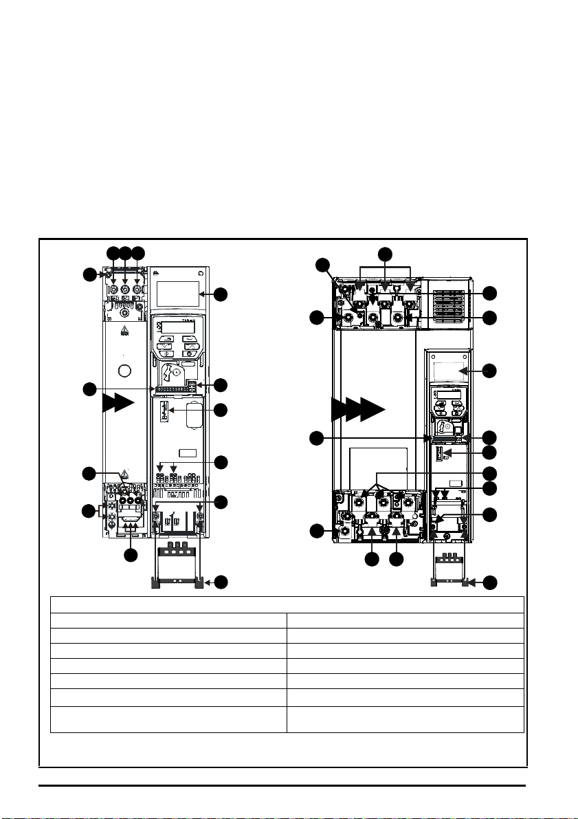
Key
1. Rating label 2. Relay connections (Refer to Fig. 6-5)
3. Option module slot 1 4. Motor connections (Refer to Fig. 6-1 to Fig. 6-4)
5. Ground connections (Refer to Fig. 6-1 to 6-4) 6. AC supply connections (Refer to Fig. 6-1 to Fig. 6-4)
7. Control connections (Refer to Fig. 6-5) 8. DC bus +
9. DC bus - 10. Braking terminal
11. Cable bracket to ground terminals
12. Internal EMC filter screw
*
13. Safe Torque Off terminals (STO)**
(Refer to Fig 6-5)
* Before removing the screw, refer to Chapter 4 in the Power Installation Guide.
** Commander C300 only
Introduction
The Commander C200 and C300 is a simple and flexible range of drives from 0.25 kW to 132 kW in 9 frame sizes
and two input voltage ranges (200 V, and 400 V).
This Step-by Step guide provides simple step-by-step instructions on how to mount the drive, fuse and cable
selection, wiring the drive-up, programming the drive and running the motor in analog input mode or keypad mode
on frames 5 to 9.
Features of the drive
Figure 1-1 Feature diagram
2 Commander C200/C300 Step By Step Guide
Issue Number: 2
Page 3
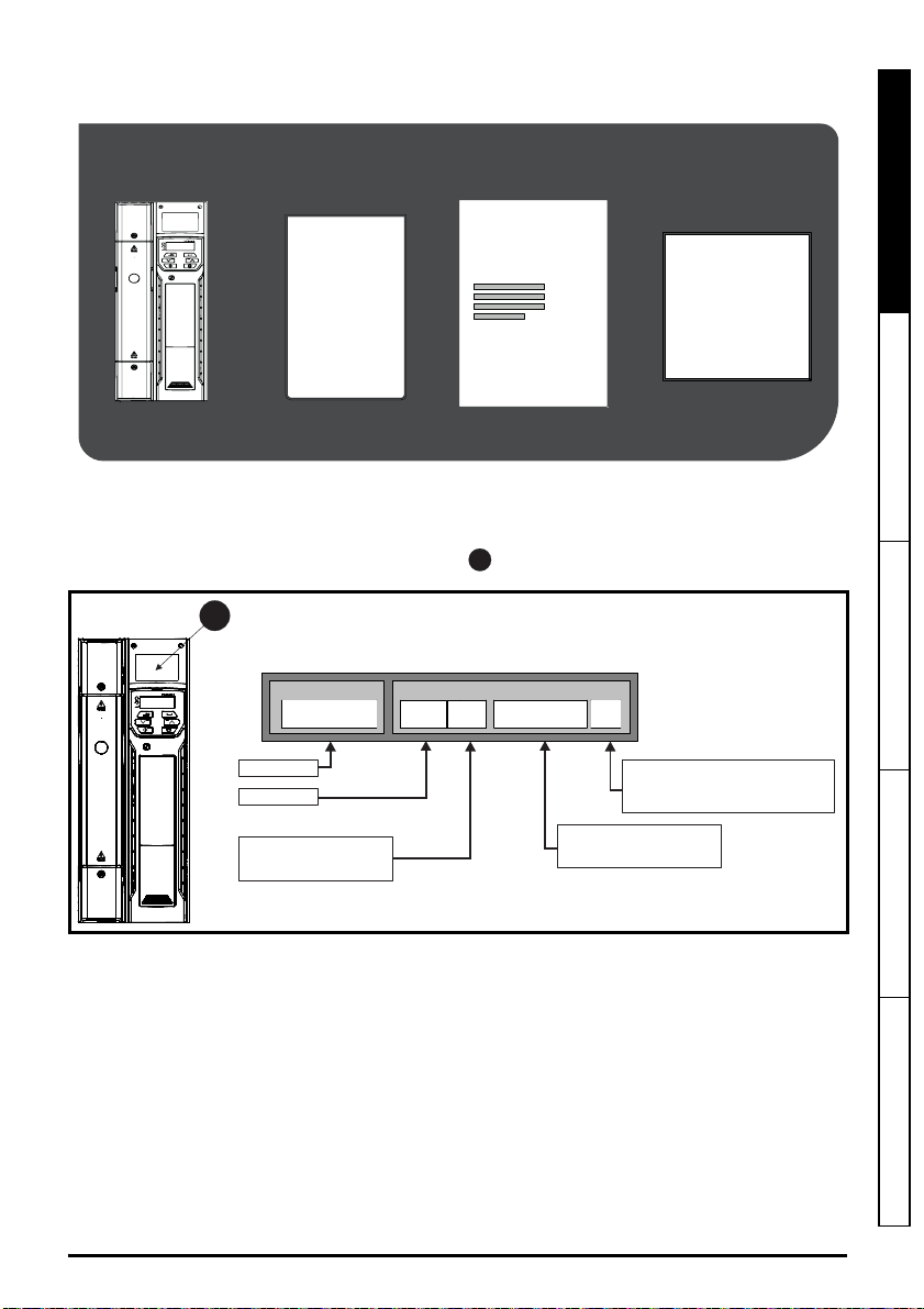
STEP 1: Check the contents of the box
KIT BOX*
SAFETY
INFORMATION
+
+
+
STEP BY
STEP
GUIDE
1
Product line:
Frame size:
Current Rating :
Heavy Duty current rating x10
Drive Format :
A - AC inAC out
E - AC in AC out (without internal choke)
Voltage rating
:
2 - 200 V (200 - 240 ± 10 %)
4 - 400 V (380 - 480 ± 10 %)
Derivative
Electrical Specifications
C300
-
05 4 00270 A
1
Check you have all the components and your drive has not been damaged during transportation.
* With frame size 7, 8 and 9, surface mounting brackets are also supplied with the drive.
STEP 2: Check model and voltage
The model number can be found on the identification label on the top of the drive. Please check that the model
and the drive voltage range is suitable for the installation.
English
Français Deutsch Italiano Español
Commander C200/C300 Step By Step Guide 3
Issue Number: 2
Page 4
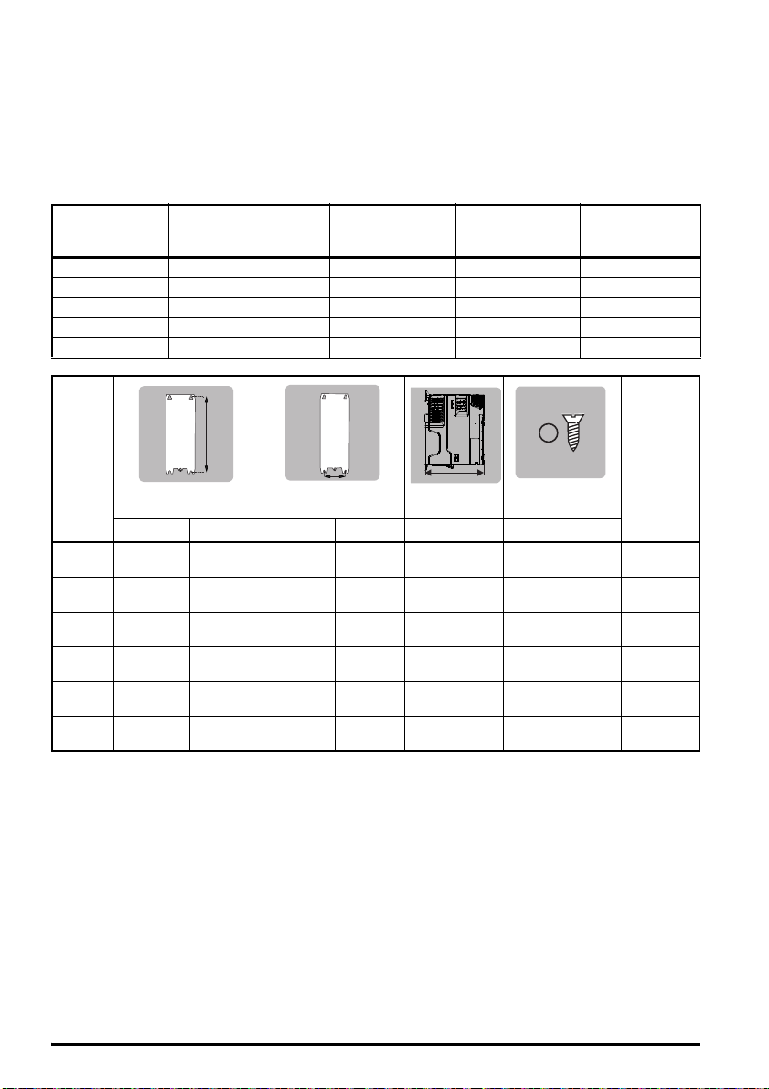
STEP 3: Mount the drive
The drive should be mounted in an ambient temperature range of - 20 °C to 60 °C (- 4 °F to 140 °F).
Output current derating may be required at ambient temperatures >40 °C (104 °F). Refer to the relevant Power
Installation Guide (section 5.1). For UL installations, the maximum ambient temperature permitted is 50 °C (122 °F)
with any specified derating applied.
The drive can be screwed on a wall or Through-panel mounted (Refer to chapter 3 in the Power Installation Guide).
Table 3-1 highlights the clearances.
Table 3-1 Recommended spacing
Frame size
5 30 mm (1.18 in) 0 mm (0.00 in) 100 mm (4.0 in) 100 mm (4.0 in)
6 30 mm (1.18 in) 0 mm (0.00 in) 100 mm (4.0 in) 100 mm (4.0 in)
7 45 mm (1.77 in) 30 mm (1.18 in) 60 mm (2.37 in) 100 mm (4.0 in)
8 45 mm (1.77 in) 30 mm (1.18 in) 60 mm (2.37 in) 100 mm (4.0 in)
9 45 mm (1.77 in) 60 mm (2.37 in) 60 mm (2.37 in) 100 mm (4.0 in)
Frame Weight
Spacing between drive
and enclosure /
EMC filter
Spacing between
drives
Spacing above
drive
Spacing below
drive
HW
Mounting Overall Mounting Overall Overall Diameter
9E
9A
375 mm
5
(14.76 in)
378 mm
6
(14.88 in)
538 mm
7
(21.18 in)
784 mm
8
(30.87 in)
1051 mm
(41.38 in)
1090 mm
(42.91 in)
391 mm
(15.39 in)
391 mm
(15.39 in)
557 mm
(21.93 in)
804 mm
(31.65 in)
1069 mm
(42.09 in)
110 8 mm
(43.62 in)
106 mm
(4.17 in)
196 mm
(7.72 in)
220 mm
(8.66 in)
259 mm
(10.20 in)
259 mm
(10.20 in)
259 mm
(10.20 in)
143 mm
(5.63 in)
210 mm
(8.27 in)
270 mm
(10.63 in)
310 mm
(12.21 in)
310 mm
(12.21 in)
310 mm
(12.21 in)
D
200 mm
(7.87 in)
227 mm
(8.94 in)
280 mm
(11.02 in)
290 mm
(11.42 in)
290 mm
(11.42 in)
290 mm
(11.42 in)
Ø
6.5 mm (0.26 in)
7.0 mm (0.28 in)
9.0 mm (0.35 in)
9.0 mm (0.35 in)
9.0 mm (0.35 in)
9.0 mm (0.35 in)
7.4 kg
(16.3 Ib)
14 kg
(30.9 Ib)
28 kg
(61.70 Ib)
52 kg
(114.6 Ib)
46 kg
(101.4 Ib)
66.5 kg
(146.6 Ib)
4 Commander C200/C300 Step By Step Guide
Issue Number: 2
Page 5
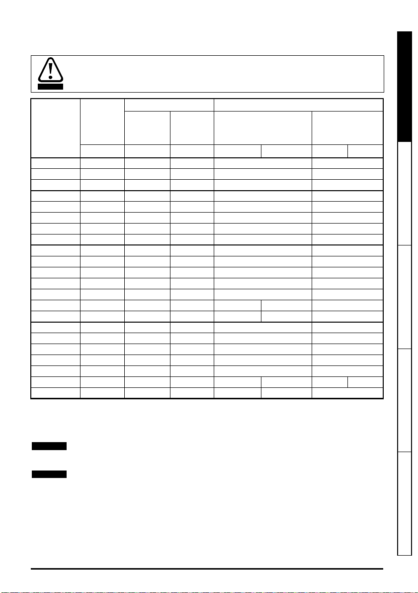
STEP 4: Select supply / motor cables and fuses
WARNING
NOTE
NOTE
The supply/motor cables and fuses or MCB’s used should follow the ratings provided in the table below:
The voltage rating of fuses must be greater than or equal to the highest supply voltage of the system.
Fuses: The AC supply to the drive must be installed with suitable protection against overload. Failure
to observe this requirement will cause risk of fire.
English
Maximum
continuous
Model
05200250 31 40 40 10 8
06200330 48.8 63 60 16 4
06200440 56.6 63 70 25 3
05400270 29 40 35 6 8
05400300 29 40 35 6 8
06400350 36 63** 40 10 6
06400420 46 63** 50 16 4
06400470 60 63** 70 25 3
07200610 67 80 80 35 2
07200750 84 100 100 35 1
07200830 105 125 125 70 1/0
08201160 137 200** 200*** 95 3/0
08201320 166 200** 225*** 2 x 70 2 x 1
09201760 205 250** 250*** 2 x 70 (B1) 2 x 95 (B2) 2 x 2/0
09202190 260 315** 300*** 2 x 95 (B1) 2 x 120 (B2) 2 x 4/0
07400660 74 100 80 35 1
07400770 88 100 100 50 2
07401000 105 125 125 70 1/0
08401340 155 250** 225*** 2 x 50 2 x 1
08401570 177 250** 225*** 2 x 70 2 x 1/0
09402000 232 315** 300*** 2 x 70 (B1) 2 x 95 (B2) 2 x 3/0 2 x 2/0
09402240 267 315** 350*** 2 x 95 (B1) 2 x 120 (B2) 2 x 4/0
input
current
A A A Input Output Input Output
Fuses Cables
IEC Class
gG or gR
UL
Class CC,
*
J, or T
IEC60364-5-52
mm²
UL 508C
AWG
* These fuses are fast acting.
** These fuses are class gR.
*** These fuses are class HSJ.
The product is UL listed for use on a circuit up to 100 kA maximum supply symmetrical fault current,
when protected by fuses.
Français Deutsch Italiano Español
IEC cable sizes assume Copper conductor, PVC insulation, Installation method B2 and ambient
temperature of 40 °C (104 °F). UL cable sizes assume Copper conductor with insulation rated at 75 °C
(167 °F).
Commander C200/C300 Step By Step Guide 5
Issue Number: 2
Page 6
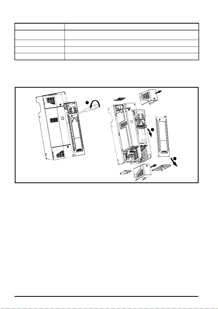
Table 4-1 Protective ground cable ratings
1
2
3
Input phase conductor size Minimum ground conductor size
≤ 10 mm²
> 10 mm² and ≤ 16 mm²
> 16 mm² and ≤ 35 mm² 16 mm²
> 35 mm²
Either 10 mm² or two conductors of the same cross-sectional area as the input
phase conductor
The same cross-sectional area as the input phase conductor
Half of the cross-sectional area of the input phase conductor
STEP 5: Remove the terminal cover and finger guard breakouts
1. Using a flat bladed screwdriver, turn the terminal cover locking clip anti-clockwise by approximately 30°.
2. Slide the terminal cover down.
3. Remove terminal cover in direction shown.
6 Commander C200/C300 Step By Step Guide
Issue Number: 2
Page 7

Removing the finger-guard break-outs
A
1
2
2
1
212
1
2
1
3
2
B
C
D
A: Size 5 to 9
B: Size 5 only
C: Size 6 only
D: Size 7 to 9
Place finger-guard on a flat solid surface and hit relevant
break-outs with hammer as shown (1). For sizes 7 to 9 pliers
can be used to remove the break-outs, grasp the relevant
break-out with the pliers and twist it as shown (3).
Continue until all required break-outs are removed (2).
Remove any flash / sharp edges once the break-outs
are removed.
Finger guard grommets are supplied in the kitbox for size 5
and 6.
English
Français Deutsch Italiano Español
STEP 6: Wire the drive up
When wiring the drive the power, ground and control connections, they should be tightened to the recommended
torque settings shown in the table below:
Table 6-1 Recommended torque settings
Model size Terminal description Torque settings
All
5
6 Power and ground terminals 6.0 N m (4.4 lb ft)
7 Power and ground terminals 12 N m (8.85 lb ft)
8 and 9 Power and ground terminals 15 N m (11.1 lb ft)
Commander C200/C300 Step By Step Guide 7
Issue Number: 2
Control terminals 0.2 N m (0.15 lb ft)
Relay terminals 0.5 N m (0.37 lb ft)
Power terminals 1.5 N m (1.1 lb ft)
Ground terminals 2.0 N m (1.4 lb ft)
Page 8

Power and Ground connections
Optional heatsink
mounted brake
resistor (M600
and above)
BR
+DC
-DC
DC / Brake connections
BR
Optional external
braking resistor
Thermal
overload
protection
device
DC -
DC +
L1 L2
L2L1 L3 U V W
Optional EMC
filter
Optional
line reactor
Fuses
L3
Mains
Supply
Motor
Optional ground
connection
Supply
Ground
PE
AC Connections Motor Connections
1
2
Connect the supply and motor connections using the cables and fuses quoted in the table shown in Step 4.
Figure 6-1 Size 5 power and ground connections
The upper terminal block (1) is used for AC supply connection.
The lower terminal block (2) is used for Motor connection.
On size 5, the supply and motor ground connections are made using the M5 studs located near the
plug-in power connector. Refer to Figure 6-1.
Issue Number: 2
8 Commander C200/C300 Step By Step Guide
Page 9

Figure 6-2 Size 6 power and ground connections
L1 L2
L2L1 L3 U V W
Optional EMC
filter
Optional
line reactor
Fuses
L3
Mains
Supply
Motor
Optional ground
connection
Supply
Ground
PE
AC Connections
BR
Optional
braking
resistor
Thermal
overload
protection
device
DC - DC +
DC Connections
(DC and braking)
Motor Connections
6
Ground connection
studs
English
On a size 6, the supply and motor ground connections are made using the M6 studs located above
the supply and motor terminals. Refer to Figure 6-2.
Français Deutsch Italiano Español
Commander C200/C300 Step By Step Guide 9
Issue Number: 2
Page 10

Figure 6-3 Size 7 and 8 power and ground connections (size 7 shown)
UVW
Motor
Optional ground
connection
+DC BR
Optional
braking
resistor
Thermal
overload
protection
device
Output connections
Input connections
Mains
Supply
L1 L2
Optional
line reactor
Optional
EMC filter
Fuses
L3
L1 L2 L3
+DC -DCPE
Supply
ground
8
On size 7 and 8, the supply and motor ground connections are made using the M8 studs located by
the supply and motor connection terminals. Refer to Figure 6-3.
10 Commander C200/C300 Step By Step Guide
Issue Number: 2
Page 11

Input connections
Mains
Supply
L1 L2
Optional
EMC filter
Fuses
L3
L1 L2 L3
PE
Supply
ground
+DC -DC
UVW
Motor
Optional ground
connection
+DC BR
Thermal
overload
protection
device
Output connections
Internal EMC
filter
9A
Figure 6-4 Size 9A power and ground connections
English
Français Deutsch Italiano Español
On size 9A, the supply and motor ground connections are made using the M10 studs located by the
supply and motor connection terminals. Refer to Figure 6-4.
Commander C200/C300 Step By Step Guide 11
Issue Number: 2
Page 12

Electrochemical corrosion of grounding terminals
WARNING
WARNING
9
10
11
12
13
14
41
42
1
2
7
4
5
31
32
35
36
24 V user
Zero frequency
Drive enable**
Run forward
Run reverse
Analog input 1/
Analog input 2 select
10 kΩ
10 kΩ
Frequency
reference 1
Frequency
reference 2
Frequency output
Digital I/O
24 V user
Digital I/O1
Digital Input 2
Digital input 3
Digital input 4
Digital input 5
Analog I/O
0V
Analog input 1
10 V user
Analog input 2
Analog output 1
Drive ok
Relay 1*
Safe Torque
Off
ST01
0V
STO1
0VSTO2
ST02
** C300 only
Ensure that grounding terminals are protected against corrosion i.e. as could be caused
by condensation.
The drive must be connected to the system ground of the AC supply. The ground wiring must
conform to local regulations and codes of practice.
The ground loop impedance must conform to the requirements of local safety regulations.
The drive must be grounded by a connection capable of carrying the prospective fault
current until the protective device (fuse, etc.) disconnects the AC supply.
The ground connections must be inspected and tested at appropriate intervals.
Table 6-2 Protective ground cable ratings
Input phase conductor size Minimum ground conductor size
≤ 10 mm²
> 10 mm² and ≤ 16 mm²
Either 10 mm² or two conductors of the same cross-sectional area as the
input phase conductor
The same cross-sectional area as the input phase conductor
> 16 mm² and ≤ 35 mm² 16 mm²
> 35 mm²
Half of the cross-sectional area of the input phase conductor
Control connections
The control terminals are configured by default for the arrangement shown below:
Figure 6-5 Commander C200/C300 control terminal connections
* 250 Vac maximum (UL class1)
** Commander C300 uses ‘Safe Torque Off’ so terminal 11 is unassigned on the Commander C300. When using a
Commander C300 refer to the 'Safe Torque Off' wiring instructions above.
After completing step 6 re-fit the terminal cover (refer to step 5).
12 Commander C200/C300 Step By Step Guide
Issue Number: 2
Page 13

STEP 7: Use the keypad
ENTER parameter view or
edit
mod
e, or to accept
a parameter edit.
UP/DOWNarrows can
be used to select
individual parameters
orto edit parameter
values.
STOP / RESET
the drive in keypad
mode. It can also be used
to reset the drive in
terminal mode.
ESCAPE
Is used to exit from the
parameter edit / view
mode.
rdy
START
Is used to start the drive in
keypad mode.
To return to Status Mode,
press button
To return to Parameter View Mode,
press button
Press or to select parameter
Status
Mode
To enter Parameter View Mode,
press button
Parameter
View Mode
Pr. 10
0.00
0.00
To view parameter value
press button
To enter Edit Mode,
press button
0.00
Edit Mode (edited digit flashes)
Holding or increases or decreases value
Parameter
Value View
To return to Parameter Value View
press button to keep the new value
press
button to ignore new value and
return the parameter to the pre-edited value
Pr. 01
rdy
The display provides information to the user regarding the operating status of the drive, alarms and trip codes.
The keypad provides the means for changing parameters, stopping and starting the drive, and the ability to perform
a drive reset.
Keypad key identifier
Instructions to edit parameters
English
Français Deutsch Italiano Español
Commander C200/C300 Step By Step Guide 13
Issue Number: 2
Page 14

STEP 8: Run the motor
Motor rated current in Pr 06 (Amps)
Motor rated speed in Pr 07 (rpm / min-1)
Motor rated voltage in Pr 08 (Volts)
Motor rated power factor in (cos φ) Pr 09
This step will provide instruction on how to set-up the basic drive parameters, perform an auto-tune and run the
motor in analog input terminal mode or keypad mode.
Action Detail
Power Up Ensure:
Minimum and
maximum speed
Accel and Decel
rates
Motor nameplate
details
Ready to autotune
Autotune The drive is able to perform either a stationary or a rotating autotune. The motor must be at
Ready to run (Analog input terminal mode by default)
Run The drive is now ready to run the motor. Close enable (C200) or Safe Torque Off (C300) and
Increasing and
decreasing speed
Stopping To stop the motor by following the selected deceleration rate, open either the run forward or
Ready to run (Keypad mode)
Run The drive is now ready to run the motor. Set Pr 05 to 'PAd'. Close enable (C200) or
Increasing and
decreasing speed
Stopping
• The drive displays: inh (Enable terminal(s) is open)
Enter:
• Minimum speed Pr 01 (Hz)
• Maximum speed Pr 02 (Hz)
Enter:
• Acceleration rate Pr 03 (s)
• Deceleration rate Pr 04 (s)
MOT. 3 LS 80 L T
734570 BJ 002 Kg 9
N
40 C S1IP 55 I cl.F
-1
V Hz min kW cos
230 50 2800 0,75 0,83 0,3
3
2
A
4
1
a standstill before any autotune is enabled and disconnected from the load for a rotating
autotune.
To perform an autotune:
•Set Pr10 to L2
• Go to Pr 38
•Set Pr38 = 1 for a stationary autotune or set Pr 38 = 2 for a rotating autotune
• Close the drive enable signal (apply +24 V to terminal 11 or terminal 31 and 35 on
Commander C300). The drive will display ‘rdy’.
• Give a Run command (apply +24 V to terminal 12 - Run forward or terminal 13 Run reverse. The display will flash ‘tuning’ while the drive is performing the autotune.
• Wait for the drive to display ‘inh’ and for the motor to come to a standstill.
• Remove the drive enable and run signal from the drive.
the Run Forward or Run Reverse terminals.
Changing the selected Analog frequency reference will increase and decrease the speed of
the motor.
run reverse terminals. If the enable terminal is opened while the motor is running, the drive
output is immediately disabled and the motor will coast to a stop.
Safe Torque Off (C300).
Press the start key
Press the up and down keys to increase and decrease the speed.
Press the Stop/Reset key
14 Commander C200/C300 Step By Step Guide
Issue Number: 2
Page 15

Additional Information
Troubleshooting
When the drive detects a fault it will display an error code. To locate and solve all error codes, a ‘Diagnostic Tool
(App)’ is available on Microsoft, Android and iOS platform via the ‘Apps’ store on Smartphone / Tablet, search for
‘Control Techniques diagnostics tool in the Apps store’. Alternatively, please download the ‘Diagnostic Tool
(App)’ from the Control Techniques ‘App Center’ or view the diagnostics section in the Control User Guide
available for download from the Control Techniques or Leroy Somer website.
Status Indicators
The table below shows the different status indicators available on the display.
Table 8-1 Status indications
String Description
The drive is inhibited and cannot be run. The Drive Enable signal is not applied
to the drive enable terminal or is set to 0.
The drive is ready to run. The drive enable is active, but the drive inverter is
not active because the final drive run is not active
The drive is stopped / holding zero speed. Enabled
Supply loss condition has been detected Enabled
The drive is applying dc injection braking Enabled
The drive has tripped and no longer controlling the motor. The trip code
appears on the display.
The drive is in the under voltage state. Disabled
Restoring drive defaults
The drive can be restored to the original factory settings by following the procedure below:
1. Ensure the drive is not enabled, i.e. terminal 11(or terminal 31 and 35 on Commander C300) is open.
2. Select ‘Def.50 (50 Hz settings) or Def.60 (60 Hz settings)’ in Pr 00.
3. Press the red reset button.
Basic parameters range and default
For information on parameters beyond Pr 00 to Pr 10 refer to the Quick Start Guide.
Parameter Range () Default ()
01 Minimum Speed 0.00 to Pr 02 Hz 0.00 Hz
02 Maximum Speed 0.00 to 550.00 Hz
03 Acceleration Rate 1 0.0 to 32000.0 s 5.0 s
04 Deceleration Rate 1 0.0 to 32000.0 s 10.0 s
AV (0), AI (1), AV.Pr (2), AI.Pr (3),
05 Drive Configuration
06 Motor Rated Current 0.00 to Drive Rating Amps
07 Motor Rated Speed 0.0 to 33000.0 rpm
08 Motor Rated Voltage 0 to 240 V or 0 to 480 V
09 Motor Rated Power Factor 0.00 to 1.00 0.85
10 User Security Status
PrESEt (4), PAd (5), PAd.rEF (6), E.Pot (7),
Refer to the Control User Guide for further
Refer to the Control User Guide for further
torquE (8), Pid (9)
information
information
Maximum Heavy Duty
400V drive Def.50: 400 V
400V drive Def.60: 460 V
Drive output
stage
Disabled
Disabled
Disabled
Def.50: 50.00 Hz
Def.60: 60.00 Hz
AV ( 0)
Rating Amps
Def.50: 1500.0 rpm
Def.60: 1800.0 rpm
110V drive: 230 V
200V drive: 230 V
LEVEL.1
English
Français Deutsch Italiano Español
Commander C200/C300 Step By Step Guide 15
Issue Number: 2
Page 16

Appendix A UL listing information
A.1 UL file reference
All models are UL Listed to both Canadian and US requirements. The UL file reference is: NMMS/7.E171230.
Products that incorporate the Safe Torque Off function have been investigated by UL. The UL file reference is:
FSPC.E171230.
A.2 Option modules, kits and accessories
Option Modules, Control Pods, Installation Kits and other accessories for use with these drives are UL Listed.
A.3 Enclosure ratings
Open Type
With the exception of free-standing cubicle drives, all models are Open Type as supplied. The drive housing is not
rated as a fire enclosure. A separate fire enclosure must be provided.
Type 1
When fitted with a conduit box the drives meet the requirements for UL Type 1. Type 1 enclosures are intended for
indoor use, primarily to provide a degree of protection against limited amounts of falling dirt.
Plenum rating with conduit box
When fitted with a conduit box, the drives comply with the requirements in the Standard for Fire Test for Heat and
Visible Smoke Release for Discrete Products and Their Accessories Installed in Air-Handling Spaces, UL 2043.
Through-hole mounting
The drives meet the requirements for UL Type 12 when installed inside a Type 12 enclosure with the heatsink
through-hole mounted using the sealing kit and the high-IP insert (where provided).
When through-hole mounted, the drives have been evaluated as suitable for use in surrounding air temperatures
up to 40 °C.
When the drive is through-panel mounted, the main terminal cover(s) must be removed in order to provide access
to the mounting holes. Once the drive has been mounted, the terminal cover(s) can be replaced.
The tightening torque of the securement brackets shall be advised as being 3 N m (26.6 lb.in).
Remote Keypads
Remote keypads are UL Type 12 when installed with the sealing washer and fixing kit provided.
A.4 Mounting
Drives may be surface, through-panel or tile mounted using the appropriate brackets. Drives may be mounted
singly or side by side with suitable space between them (bookcase mounting).
A.5 Environment
Drives must be installed in a Pollution Degree 2 environment or better (dry, non-conductive pollution only).
The drives have been evaluated for use at ambient temperatures up to 40 °C. The drives have additionally been
evaluated for 50 °C and 55 °C ambient air temperatures with a derated output.
A.6 Electrical Installation
OVERVOLTAGE CATEGORY
Drives have been evaluated for OVC III.
SUPPLY
The drives are suitable for use on a circuit capable of delivering not more than 100,000 RMS symmetrical amperes,
600 Volts AC Maximum.
TERMINAL TORQUE
Terminals must be tightened to the rated torque as specified in the Installation Instructions.
WIRING TERMINALS
Drives must be installed using cables rated for 75 °C operation, copper wire only.
Where possible, UL Listed closed-loop connectors sized according to the field wiring shall be used for all field
power wiring connections.
16 Commander C200/C300 Step By Step Guide
Issue Number: 2
Page 17

GROUND CONNECTION INSTRUCTIONS
UL Listed closed-loop connectors sized according to the field wiring shall be used for grounding connections.
BRANCH CIRCUIT PROTECTION
The fuses and circuit breakers required for branch circuit protection are specified in the Installation Instructions.
OPENING OF BRANCH CIRCUIT
Opening of the branch-circuit protective device may be an indication that a fault has been interrupted. To reduce the
risk of fire or electric shock, the equipment should be examined and replaced if damaged. If burnout of the current
element of an overload relay occurs, the complete overload relay must be replaced.
Integral solid state short circuit protection does not provide branch circuit protection. Branch circuit protection must
be provided in accordance with the National Electrical Code (NEC), The Canadian Electrical Code, and any
additional local codes.
A.7 Motor overload protection and thermal memory retention
The devices incorporate solid state overload protection for the motor load. The protection levels are expressed as a
percentage of full-load current. Refer to the Control User Guide for further information.
In order for the motor protection to work properly, the motor rated current must be entered into Pr 06 or Pr 05.007.
The protection level may be adjusted below 150 % if required. Refer to the Control User Guide for further information.
All models are provided with thermal memory retention.
A.8 External Class 2 supply
The external power supply used to power the 24 V control circuit shall be marked: "UL Class 2". The power supply
voltage shall not exceed 24 Vdc.
A.9 Modular Drive Systems
Drives with DC+ and DC- supply connections, rated 230 V or 480 V have been investigated for use in Modular Drive
Systems as inverters when supplied by the converter sections from the Unidrive-M range. In these applications the
inverters are required to be additionally protected by supplemental fuses.
Alternatively, the inverters may be supplied by converter models: Mentor MP25A, 45A, 75A, 105A, 155A or 210A.
Contact the supplier of the drive for more information.
A.10 Requirement for Transient Surge Suppression
This requirement only applies to Frame Size 7 drives with rated input voltage = 575 V.
TRANSIENT SURGE SUPPRESSION SHALL BE INSTALLED ON THE LINE SIDE OF THIS EQUIPMENT
AND SHALL BE RATED 575 Vac (PHASE TO GROUND), 575 Vac (PHASE TO PHASE), SUITABLE FOR
OVERVOLTAGE CATEGORY III, AND SHALL PROVIDE PROTECTION FOR A RATED IMPULSE VOLTAGE
TO WITHSTAND VOLTAGE PEAK OF 6 kV AND A CLAMPING VOLTAGE OF MAXIMUM 2400 V.
English
Français Deutsch Italiano Español
Commander C200/C300 Step By Step Guide 17
Issue Number: 2
 Loading...