

Control Techniques Commander C200, Commander C300, Unidrive M100, Unidrive M400 Installation Manual
Page 1

Page 2
Original Instructions
For the purposes of compliance with the EU Machinery Directive 2006/42/EC, the English version of this manual is
the Original Instructions. Manuals in other languages are Translations of the Original Instructions.
Documentation
The information contained in this manual is believed to be correct at the time of printing and does not form part of
any contract. The manufacturer reserves the right to change the specification of the product and its performance,
and the contents of the manual, without notice.
Warranty and Liability
In no event and under no circumstances shall the manufacturer be liable for damages and failures due to misuse,
abuse, improper installation, or abnormal conditions of temperature, dust, or corrosion, or failures due to operation
outside the published ratings. The manufacturer is not liable for consequential and incidental damages. Contact the
supplier of the dive for full details of the warranty terms.
Environmental policy
Control Techniques Ltd operates an Environmental Management System (EMS) that conforms to the International
Standard ISO 14001.
Restriction of Hazardous Substances (RoHS)
The products covered by this manual comply with European and International regulations on the Restriction of Hazardous Substances including EU directive 2011/65/EU and the Chinese Administrative Measures for Restriction of
Hazardous Substances in Electrical and Electronic Products.
Disposal and Recycling (WEEE)
When electronic products reach the end of their useful life, they must not be disposed of along
with domestic waste but should be recycled by a specialist recycler of electronic equipment.
Control Techniques products are designed to be easily dismantled into their major component
parts for efficient recycling. The majority of materials used in the product are suitable for
recycling.
Product packaging is of good quality and can be re-used. Large products are packed in wooden
crates. Smaller products are packaged in strong cardboard cartons which have a high recycled
fibre content. Cartons can be re-used and recycled. Polythene, used in protective film and bags
for wrapping the product, can be recycled. When preparing to recycle or dispose of any product
or packaging, please observe local legislation and best practice.
REACH legislation
EC Regulation 1907/2006 on the Registration, Evaluation, Authorisation and restriction of Chemicals (REACH)
requires the supplier of an article to inform the recipient if it contains more than a specified proportion of any
substance which is considered by the European Chemicals Agency (ECHA) to be a Substance of Very High
Concern (SVHC) and is therefore listed by them as a candidate for compulsory authorisation.
.
Page 3

Copyright
The contents of this publication are believed to be correct at the time of printing. In the interests of a commitment to
a policy of continuous development and improvement, the manufacturer reserves the right to change the
specification of the product or its performance, or the contents of the guide, without notice.
All rights reserved. No parts of this guide may be reproduced or transmitted in any form or by any means, electrical
or mechanical including photocopying, recording or by an information storage or retrieval system, without
permission in writing from the publisher.
Copyright © November 2018 Nidec Control Techniques Ltd
Page 4

Contents
1 Safety information .....................................................................................11
1.1 Warnings, Cautions and Notes ..............................................................................11
1.2 Important safety information. Hazards. Competence of designers and installers ..11
1.3 Responsibility ......................................................................................................... 11
1.4 Compliance with regulations ..................................................................................11
1.5 Electrical hazards ...................................................................................................12
1.6 Stored electrical charge .........................................................................................12
1.7 Mechanical hazards ............................................................................................... 12
1.8 Access to equipment ..............................................................................................12
1.9 Environmental limits ...............................................................................................12
1.10 Hazardous environments .......................................................................................13
1.11 Motor ......................................................................................................................13
1.12 Mechanical brake control ....................................................................................... 13
1.13 Adjusting parameters ............................................................................................. 13
1.14 Electromagnetic compatibility (EMC) .....................................................................13
2 Product information ..................................................................................14
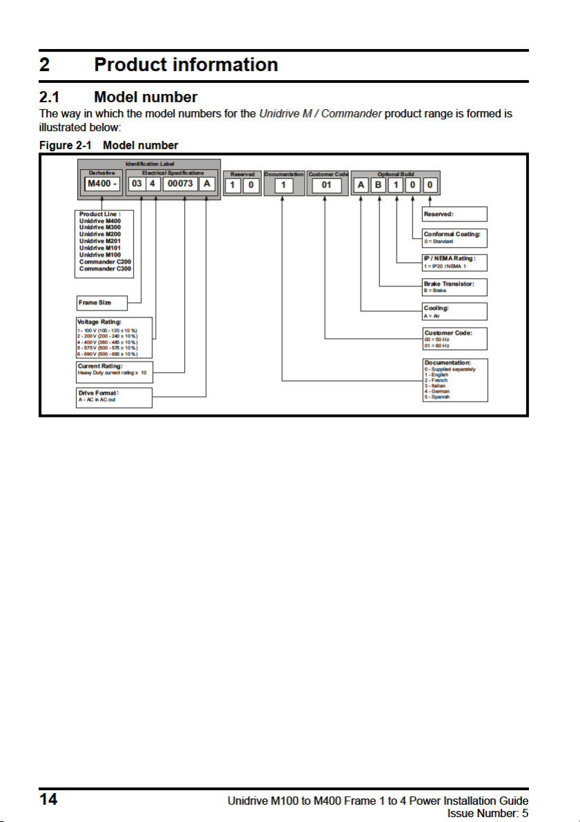
2.1 Model number ........................................................................................................14
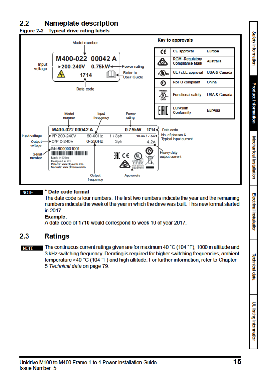
2.2 Nameplate description ...........................................................................................15
2.3 Ratings ...................................................................................................................15
2.4 Drive features .........................................................................................................18
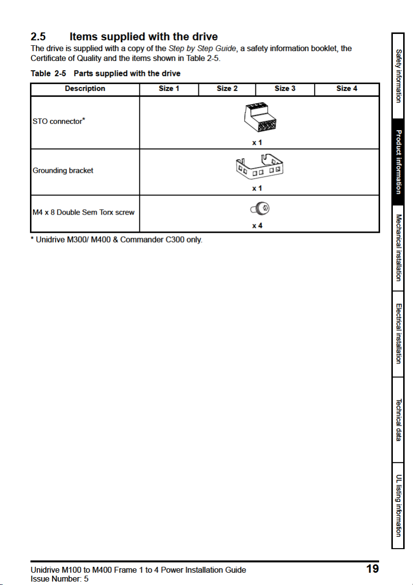
2.5 Items supplied with the drive ..................................................................................19
3 Mechanical installation .............................................................................20
3.1 Safety information .................................................................................................. 20
3.2 Planning the installation .........................................................................................20
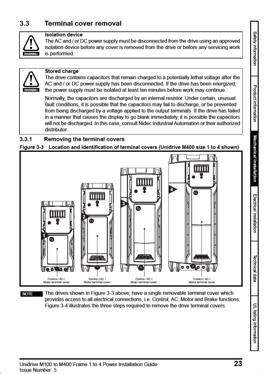
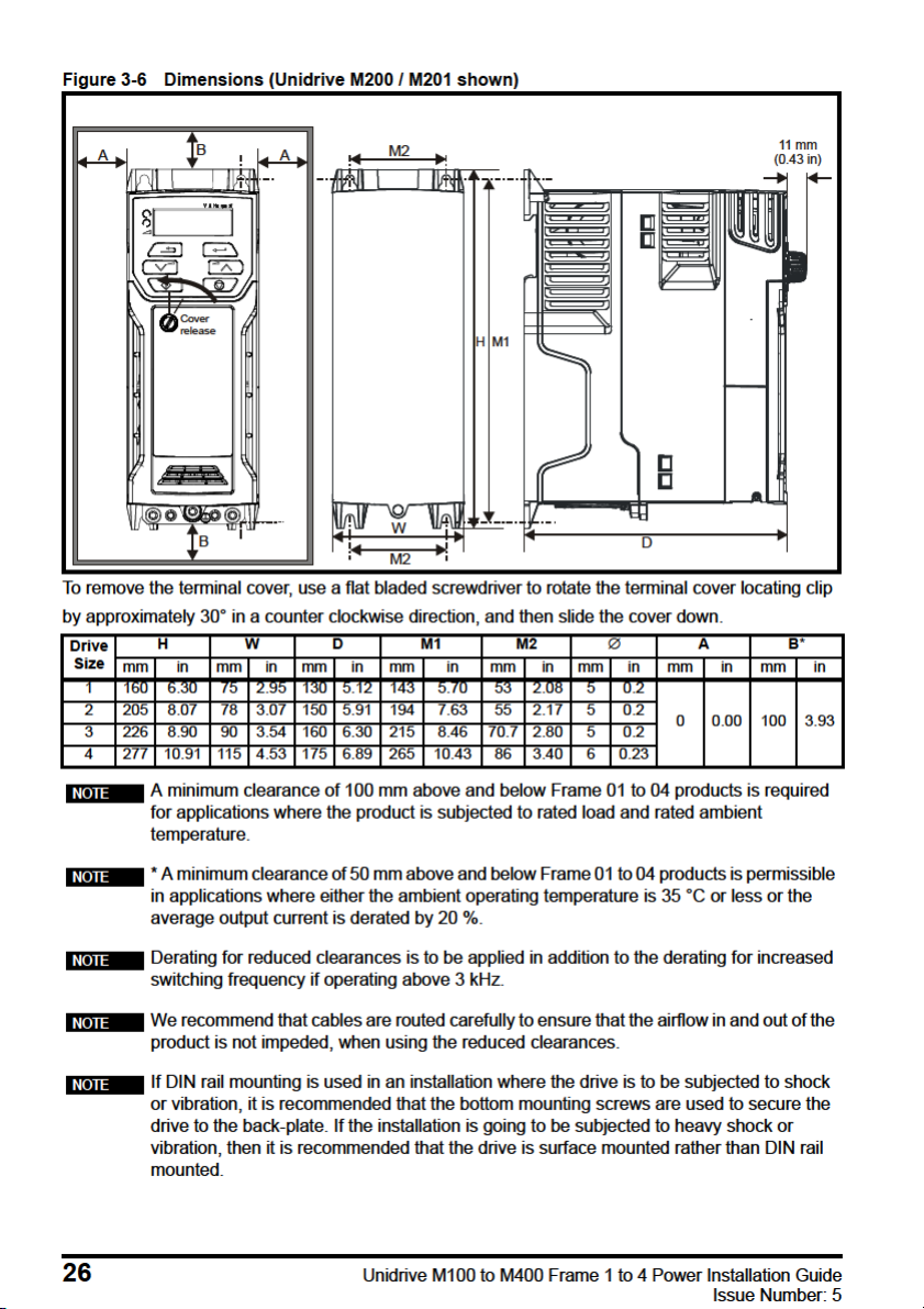
3.3 Terminal cover removal ..........................................................................................23
3.4 Drive dimensions and mounting methods ..............................................................25
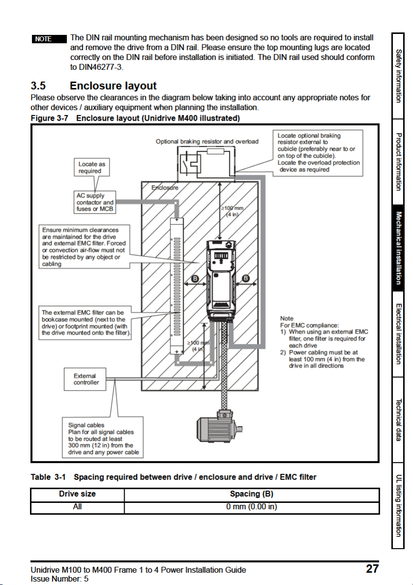
3.5 Enclosure layout .....................................................................................................27
3.6 Heatsink fan operation ...........................................................................................31
3.7 External EMC filter ................................................................................................. 32
3.8 Electrical terminals .................................................................................................37
3.9 Routine maintenance ............................................................................................. 39
4 Electrical installation .................................................................................41
4.1 Power connections .................................................................................................42
4.2 AC supply requirements .........................................................................................45
4.3 Ratings ...................................................................................................................51
4.4 Output circuit and motor protection ........................................................................55
4.5 Braking ................................................................................................................... 60
4.6 Ground leakage ...................................................................................................... 64
4.7 EMC (Electromagnetic compatibility) .....................................................................65
5 Technical data ............................................................................................79
5.1 Drive technical data ................................................................................................79
5.2 Optional external EMC filters ...............................................................................100
6 UL listing information ..............................................................................103
6.1 UL file reference ...................................................................................................103
6.2 Option modules, kits and accessories ..................................................................103
6.3 Enclosure ratings .................................................................................................103
6.4 Mounting .............................................................................................................. 103
6.5 Environment ......................................................................................................... 103
6.6 Electrical Installation ............................................................................................104
6.7 Motor overload protection and thermal memory retention ...................................104
6.8 Electrical supply ...................................................................................................105
6.9 External Class 2 supply ........................................................................................105
6.10 Group Installation and Modular Drive Systems ....................................................105
Unidrive M100 to M400 Frame 1 to 4 Power Installation Guide
Issue Number: 5
Page 5
EU Declaration of Conformity
G Williams
Vice President, Technology
Date: 17th March 2016
Nidec Control Techniques Ltd
This declaration is issued under the sole responsibility of the manufacturer. The object of the declaration is in
conformity with the relevant European Union harmonization legislation. The declaration applies to the variable
speed drive products shown below:
Model
number
aaaa Basic series
bb Frame size 01, 02, 03, 04, 05, 06, 07, 08, 09, 10, 11
c Voltage rating 1 = 100 V, 2 = 200 V, 4 = 400 V, 5 = 575 V, 6 = 690 V
ddddd Current rating Example 01000 = 100 A
e Drive format
The model number may be followed by additional characters that do not affect the ratings.
The variable speed drive products listed above have been designed and manufactured in accordance with the
following European harmonized standards:
EN 61800-5-1:2007
EN 61800-3: 2004+A1:2012
EN 61000-6-2:2005
EN 61000-6-4: 2007+A1:2011
EN 61000-3-2:2014
EN 61000-3-3:2013
EN 61000-3-2:2014 Applicable where input current < 16 A. No limits apply for professional equipment where input
power 1 kW.
These products comply with the Restriction of Hazardous Substances Directive (2011/65/EU), the Low Voltage
Directive (2014/35/EU) and the Electromagnetic Compatibility Directive (2014/30/EU).
Interpretation Nomenclature aaaa - bbc ddddde
M100, M101, M200, M201, M300, M400, M600, M700, M701, M702, F300,
H300, E200, E300, HS30, HS70, HS71, HS72, M000, RECT
A = 6P Rectifier + Inverter (internal choke), D = Inverter, E = 6P Rectifier +
Inverter (external choke), T = 12P Rectifier + Inverter (external choke)
Adjustable speed electrical power drive systems - Part 5-1: Safety requirements Electrical, thermal and energy
Adjustable speed electrical power drive systems - Part 3: EMC requirements and
specific test methods
Electromagnetic compatibility (EMC) - Part 6-2: Generic standards - Immunity for
industrial environments
Electromagnetic compatibility (EMC) - Part 6-4: Generic standards - Emission
standard for industrial environments
Electromagnetic compatibility (EMC) - Part 3-2: Limits for harmonic current
emissions (equipment input current ≤16 A per phase)
Electromagnetic compatibility (EMC) - Part 3-3: Limitation of voltage changes,
voltage fluctuations and flicker in public, low voltage supply systems, for
equipment with rated current ≤16 A per phase and not subject to conditional
connection
These electronic drive products are intended to be used with appropriate motors, controllers, electrical
protection components and other equipment to form complete end products or systems. Compliance with
safety and EMC regulations depends upon installing and configuring drives correctly, including using the
specified input filters.
The drives must be installed only by professional installers who are familiar with requirements for safety
and EMC. Refer to the Product Documentation. An EMC data sheet is available giving detailed information.
The assembler is responsible for ensuring that the end product or system complies with all the relevant
laws in the country where it is to be used.
Unidrive M100 to M400 Frame 1 to 4 Power Installation Guide 5
Issue Number: 5
Page 6
EU Declaration of Conformity
Jon Holman-White
Director of Research and Development
Date: 9th October 2018
Nidec Control Techniques Ltd
The Gro
This declaration is issued under the sole responsibility of the manufacturer. The object of the declaration is in
conformity with the relevant European Union harmonization legislation. The declaration applies to the variable
speed drive products shown below:
Model
number
aaaa Basic series C200, C300,
bb Frame size 01, 02, 03, 04, 05, 06, 07, 08, 09
c Voltage rating 1 = 100 V, 2 = 200 V, 4 = 400
ddddd Current rating Example 01000 = 100 A
e Drive format
The model number may be followed by other characters that do not affect the ratings.
The variable speed drive products listed above have been designed and manufactured in accordance with the
following European harmonized standards:
EN 61800-5-1:2007
EN 61800-3: 2004+A1:2012
EN 61000-6-2:2005
EN 61000-6-4: 2007+A1:2011
EN 61000-3-2:2014
EN 61000-3-3:2013
EN 61000-3-2:2014 Applicable where input current < 16 A. No limits apply for professional equipment where input
power 1 kW.
These products comply with the Restriction of Hazardous Substances Directive (2011/65/EU), the Low Voltage
Directive (2014/35/EU) and the Electromagnetic Compatibility Directive (2014/30/EU).
Interpretation Nomenclature aaaa - bbc ddddde
A = 6P Rectifier + Inverter with internal choke, E = 6P Rectifier + Inverter
(external choke)
Adjustable speed electrical power drive systems - Part 5-1: Safety requirements Electrical, thermal and energy
Adjustable speed electrical power drive systems - Part 3: EMC requirements and
specific test methods
Electromagnetic compatibility (EMC) - Part 6-2: Generic standards - Immunity for
industrial environments
Electromagnetic compatibility (EMC) - Part 6-4: Generic standards - Emission
standard for industrial environments
Electromagnetic compatibility (EMC) - Part 3-2: Limits for harmonic current
emissions (equipment input current ≤16 A per phase)
Electromagnetic compatibility (EMC) - Part 3-3: Limitation of voltage changes,
voltage fluctuations and flicker in public, low voltage supply systems, for
equipment with rated current ≤16 A per phase and not subject to conditional
connection
These electronic drive products are intended to be used with appropriate motors, controllers, electrical
protection components and other equipment to form complete end products or systems. Compliance with
safety and EMC regulations depends upon installing and configuring drives correctly, including using the
specified input filters.
The drives must be installed only by professional installers who are familiar with requirements for safety
and EMC. Refer to the Product Documentation. An EMC data sheet is available giving detailed information.
The assembler is responsible for ensuring that the end product or system complies with all the relevant
laws in the country where it is to be used.
6 Unidrive M100 to M400 Frame 1 to 4 Power Installation Guide
Issue Number: 5
Page 7
E U De c l a ra t i o n o f C o nf o r m it y
(including 2006 Machinery Directive)
Nidec Control Techniques Ltd
The Gro
This declaration is issued under the sole responsibility of the manufacturer. The object of the declaration is in
conformity with the relevant European Union harmonization legislation. The declaration applies to the variable
speed drive products shown below:
Model
number
aaaa Basic series
bb Frame size 01, 02, 03, 04, 05, 06, 07, 08, 09, 10, 11
c Voltage rating 1 = 100 V, 2 = 200 V, 4 = 400 V, 5 = 575 V, 6 = 690 V
ddddd Current rating Example 01000 = 100 A
e Drive format
The model number may be followed by additional characters that do not affect the ratings.
This declaration relates to these products when used as a safety component of a machine. Only the Safe
Torque Off function may be used for a safety function of a machine. None of the other functions of the drive
may be used to carry out a safety function.
These products fulfil all the relevant provisions of the Machinery Directive 2006/42/EC and the Electromagnetic
Compatibility Directive (2014/30/EU).
EC type examination has been carried out by the following notified body:
TUV Rheinland Industrie Service GmbH
Am Grauen Stein
D-51105 Köln
Germany
EC type-examination certificate numbers:
01/205/5270.01/14 dated 2014-11-11
01/205/5387.01/15 dated 2015-01-29
01/205/5383.02/15 dated 2015-04-21
Notified body identification number: 0035
The harmonized standards used are shown below:
EN 61800-5-1:2007
EN 61800-5-2:2007
EN ISO 13849-1:2008
EN ISO 13849-2:2008 Safety of machinery, Safety-related parts of control systems. Validation
EN 61800-3: 2004+A1:2012
EN 62061:2005
Interpretation Nomenclature aaaa - bbc ddddde
M300, M400, M600, M700, M701, M702, F300, H300, E200, E300, HS30,
HS70, HS71, HS72, M000, RECT
A = 6P Rectifier + Inverter (internal choke), D = Inverter, E = 6P Rectifier +
Inverter (external choke), T = 12P Rectifier + Inverter (external choke)
Adjustable speed electrical power drive systems - Part 5-1: Safety requirements
- Electrical, thermal and energy
Adjustable speed electrical power drive systems - Part 5-2: Safety requirements
- Functional
Safety of Machinery, Safety-related parts of control systems, General principles
for design
Adjustable speed electrical power drive systems - Part 3: EMC requirements
and specific test methods
Safety of machinery, Functional safety of safety related electrical, electronic
and programmable electronic control systems
Unidrive M100 to M400 Frame 1 to 4 Power Installation Guide 7
Issue Number: 5
Page 8

Person authorised to complete the technical file:
G. Williams
Vice President, Technology
Date: 17th March 2016
Place: Newtown, Powys, UK
P Knight
Conformity Engineer
Newtown, Powys, UK
IMPORTANT NOTICE
These electronic drive products are intended to be used with appropriate motors, controllers, electrical
protection components and other equipment to form complete end products or systems. Compliance with
safety and EMC regulations depends upon installing and configuring drives correctly, including using the
specified input filters.
The drives must be installed only by professional installers who are familiar with requirements for safety
and EMC. Refer to the Product Documentation. An EMC data sheet is available giving detailed information.
The assembler is responsible for ensuring that the end product or system complies with all the relevant
laws in the country where it is to be used.
8 Unidrive M100 to M400 Frame 1 to 4 Power Installation Guide
Issue Number: 5
Page 9

E U De c l a ra t i o n o f C o nf o r m it y
(including 2006 Machinery Directive)
Nidec Control Techniques Ltd
The Gro
This declaration is issued under the sole responsibility of the manufacturer. The object of the declaration is in
conformity with the relevant European Union harmonization legislation. The declaration applies to the variable
speed drive products shown below:
Model
number
aaaa Basic series C300
bb Frame size 01, 02, 03, 04, 05, 06, 07, 08, 09
c Voltage rating 1 = 100 V, 2 = 200 V, 4 = 400 V
ddddd Current rating Example 01000 = 100 A
e Drive format
The model number may be followed by additional characters that do not affect the ratings.
This declaration relates to these products when used as a safety component of a machine. Only the Safe
Torque Off function may be used for a safety function of a machine. None of the other functions of the drive
may be used to carry out a safety function.
These products fulfil all the relevant provisions of the Machinery Directive (2006/42/EC) and the Electromagnetic
Compatibility Directive (2014/30/EU).
EC type examination has been carried out by the following notified body:
TUV Rheinland Industrie Service GmbH
Am Grauen Stein
D-51105 Köln
Germany
Interpretation Nomenclature aaaa - bbc ddddde
A = 6P Rectifier + Inverter with internal choke, E = 6P Rectifier + Inverter
(external choke)
EC type-examination certificate numbers:
Frame sizes 1 to 4: 01/205/5383.03/18 dated 2018-08-16
Frame sizes 5 to 9: 01/205/5387.02/18 dated 2018-08-16
Notified body identification number: 0035
The harmonized standards used are shown below:
EN 61800-5-2:2007
EN 61800-5-1:2007 (in
extracts)
EN 61800-3: 2004+A1:2012
EN ISO 13849-1:2008 +
AC:2009
EN 62061:2005 + AC:2010
+ A1:2013
IEC 61508 Parts 1 - 7:2010
Adjustable speed electrical power drive systems - Part 5-2: Safety requirements
- Functional
Adjustable speed electrical power drive systems - Part 5-1: Safety requirements
- Electrical, thermal and energy
Adjustable speed electrical power drive systems - Part 3: EMC requirements
and specific test methods
Safety of Machinery, Safety-related parts of control systems, General principles
for design
Safety of machinery, Functional safety of safety related electrical, electronic
and programmable electronic control systems
Functional safety of electrical/ electronic/programmable electronic safetyrelated systems
Unidrive M100 to M400 Frame 1 to 4 Power Installation Guide 9
Issue Number: 5
Page 10

Person authorised to complete the technical file:
Jon Holman-White
Director of Research and Development
Date: 9th October 2018
Place: Newtown, Powys, UK
P Knight
Conformity Engineer
Newtown, Powys, UK
IMPORTANT NOTICE
These electronic drive products are intended to be used with appropriate motors, controllers, electrical
protection components and other equipment to form complete end products or systems. It is the
responsibility of the installer to ensure that the design of the complete machine, including its safety-related
control system, is carried out in accordance with the requirements of the Machinery Directive and any
other relevant legislation. The use of a safety-related drive in itself does not ensure the safety of the
machine. Compliance with safety and EMC regulations depends upon installing and configuring drives
correctly, including using the specified input filters. The drive must be installed only by professional
installers who are familiar with requirements for safety and EMC. The assembler is responsible for
ensuring that the end product or system complies with all relevant laws in the country where it is to be
used. For more information regarding Safe Torque Off, refer to the Product Documentation.
10 Unidrive M100 to M400 Frame 1 to 4 Power Installation Guide
Issue Number: 5
Page 11
Page 12

2014/30/EU: Electromagnetic Compatibility.
1.5 Electrical hazards
The voltages used in the drive can cause severe electrical shock and/or burns, and could be lethal.
Extreme care is necessary at all times when working with or adjacent to the drive. Hazardous voltage
may be present in any of the following locations:
• AC and DC supply cables and connections
• Output cables and connections
• Many internal parts of the drive, and external option units
Unless otherwise indicated, control terminals are single insulated and must not be touched.
The supply must be disconnected by an approved electrical isolation device before gaining access to
the electrical connections.
The STOP and Safe Torque Off functions of the drive do not isolate dangerous voltages from the
output of the drive or from any external option unit.
The drive must be installed in accordance with the instructions given in this guide. Failure to observe
the instructions could result in a fire hazard.
1.6 Stored electrical charge
The drive contains capacitors that remain charged to a potentially lethal voltage after the AC supply
has been disconnected. If the drive has been energized, the AC supply must be isolated at least ten
minutes before work may continue.
1.7 Mechanical hazards
Careful consideration must be given to the functions of the drive or controller which might result in a
hazard, either through their intended behaviour or through incorrect operation due to a fault. In any
application where a malfunction of the drive or its control system could lead to or allow damage, loss
or injury, a risk analysis must be carried out, and where necessary, further measures taken to reduce
the risk - for example, an over-speed protection device in case of failure of the speed control, or a
fail-safe mechanical brake in case of loss of motor braking.
With the sole exception of the Safe Torque Off function, none of the drive functions must be
used to ensure safety of personnel, i.e. they must not be used for safety-related functions.
The Safe Torque Off function may be used in a safety-related application. The system designer is
responsible for ensuring that the complete system is safe and designed correctly according to the
relevant safety standards.
The design of safety-related control systems must only be done by personnel with the required
training and experience. The Safe Torque Off function will only ensure the safety of a machine if it is
correctly incorporated into a complete safety system. The system must be subject to a risk
assessment to confirm that the residual risk of an unsafe event is at an acceptable level for the
application.
1.8 Access to equipment
Access must be restricted to authorized personnel only. Safety regulations which apply at the place
of use must be complied with.
1.9 Environmental limits
Instructions in this guide regarding transport, storage, installation and use of the equipment must be
complied with, including the specified environmental limits. This includes temperature, humidity,
contamination, shock and vibration. Drives must not be subjected to excessive physical force.
12 Unidrive M100 to M400 Frame 1 to 4 Power Installation Guide
Issue Number: 5
Page 13

1.10 Hazardous environments
The equipment must not be installed in a hazardous environment (i.e. a potentially explosive
environment).
1.11 Motor
The safety of the motor under variable speed conditions must be ensured.
To avoid the risk of physical injury, do not exceed the maximum specified speed of the motor.
Low speeds may cause the motor to overheat because the cooling fan becomes less effective,
causing a fire hazard. The motor should be installed with a protection thermistor. If necessary, an
electric forced vent fan should be used.
The values of the motor parameters set in the drive affect the protection of the motor. The default
values in the drive must not be relied upon. It is essential that the correct value is entered in the
Motor Rated Current parameter.
1.12 Mechanical brake control
Any brake control functions are provided to allow well co-ordinated operation of an external brake
with the drive. While both hardware and software are designed to high standards of quality and
robustness, they are not intended for use as safety functions, i.e. where a fault or failure would result
in a risk of injury. In any application where the incorrect operation of the brake release mechanism
could result in injury, independent protection devices of proven integrity must also be incorporated.
1.13 Adjusting parameters
Some parameters have a profound effect on the operation of the drive. They must not be altered
without careful consideration of the impact on the controlled system. Measures must be taken to
prevent unwanted changes due to error or tampering.
1.14 Electromagnetic compatibility (EMC)
Installation instructions for a range of EMC environments are provided in the relevant Power
Installation Guide. If the installation is poorly designed or other equipment does not comply with
suitable standards for EMC, the product might cause or suffer from disturbance due to
electromagnetic interaction with other equipment. It is the responsibility of the installer to ensure that
the equipment or system into which the product is incorporated complies with the relevant EMC
legislation in the place of use.
Safety information
Product information Mechanical installation Electrical installation Technical data UL listing information
Unidrive M100 to M400 Frame 1 to 4 Power Installation Guide 13
Issue Number: 5
Page 14
Page 15
Page 16
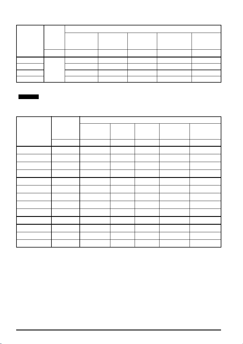
Table 2-1 100 V drive ratings (100 V to 120 V ±10 %)
NOTE
Heavy Duty
Model
Input
phases
Maximum
continuous
output current
Open loop
peak current
RFC peak
current
Nominal power
at
200 V
Motor power
ph A A A kW hp
01100017
01100024 2.4 3.6 4.3 0.37 0.5
02100042 4.2 6.3 7.6 0.75 1
1
1.7 2.6 3.1 0.25 0.33
02100056 5.6 8.4 10.1 1.1 1.5
The 100 V drives have a voltage doubler circuit on the input, therefore the output voltage
is 200 V.
Table 2-2 200 V drive ratings (200 V to 240 V ±10 %)
Heavy Duty
Model
01200017 1 1.7 2.6 3.1 0.25 0.33
01200024 1 2.4 3.6 4.3 0.37 0.5
01200033 1 3.3 5 5.9 0.55 0.75
01200042 1 4.2 6.3 7.6 0.75 1
02200024 1/3 2.4 3.6 4.3 0.37 0.5
02200033 1/3 3.3 5 5.9 0.55 0.75
02200042 1/3 4.2 6.3 7.6 0.75 1
02200056 1/3 5.6 8.4 10.1 1.1 1
02200075 1/3 7.5 11.3 13.5 1.5 2
03200100 1/3 10 15 18 2.2 3
04200133 1/3 13.3 20 23.9 3 3
04200176 1 13.3 20 23.9 3 3
04200176 3 17.6 26.4 31.7 4 5
Input phases
ph A A A kW hp
Maximum
continuous
output current
Open loop
peak current
RFC peak
current
Nominal power
at 230 V
at 200 V
Motor power
at 230 V
16 Unidrive M100 to M400 Frame 1 to 4 Power Installation Guide
Issue Number: 5
Page 17

Table 2-3 400 V drive ratings (380 V to 480 V ±10 %)
NOTE
Heavy Duty
Model
02400013
02400018 1.8 2.7 3.2 0.55 0.75
02400023 2.3 3.5 4.1 0.75 1
02400032 3.2 4.8 5.8 1.1 1.5
02400041 4.1 6.2 7.4 1.5 2
03400056
03400073 7.3 11 13.1 3 3
03400094 9.4 14.1 16.9 4 5
04400135
04400170 17 25.5 30.6 7.5 10
Input phases
ph A A A kW hp
3
3
3
Maximum
continuous
output current
1.3 2 2.3 0.37 0.5
5.6 8.4 10.1 2.2 3
13.5 20.3 24.3 5.5 7.5
Open loop
peak current
R F C p e a k
current
Nominal
power at 400 V
Motor power
at 460 V
2.3.1 Typical short term overload limits
The maximum percentage overload limit changes depending on the selected motor. Variations in
motor rated current, motor power factor and motor leakage inductance all result in changes in the
maximum possible overload. The exact value for a specific motor can be calculated using the
equations detailed in Menu 4 in the Parameter Reference Guide.
Typical values are shown in the table below for RFC-A and open loop (OL) modes:
Table 2-4 Typical overload limits
Operating mode RFC From cold RFC From 100 %
Heavy Duty overload with motor
rated current = drive rated
current
180 % for 3 s 180 % for 3 s 150 % for 60 s 150 % for 8 s
Open loop from
cold
Open loop from
100 %
Safety information
Product information
Mechanical installation Electrical installation Technical data UL listing information
Generally the drive rated current is higher than the matching motor rated current allowing a higher
level of overload than the default setting.
The time allowed in the overload region is proportionally reduced at very low output frequency on
some drive ratings.
The maximum overload level which can be attained is independent of the speed.
Unidrive M100 to M400 Frame 1 to 4 Power Installation Guide 17
Issue Number: 5
Page 18
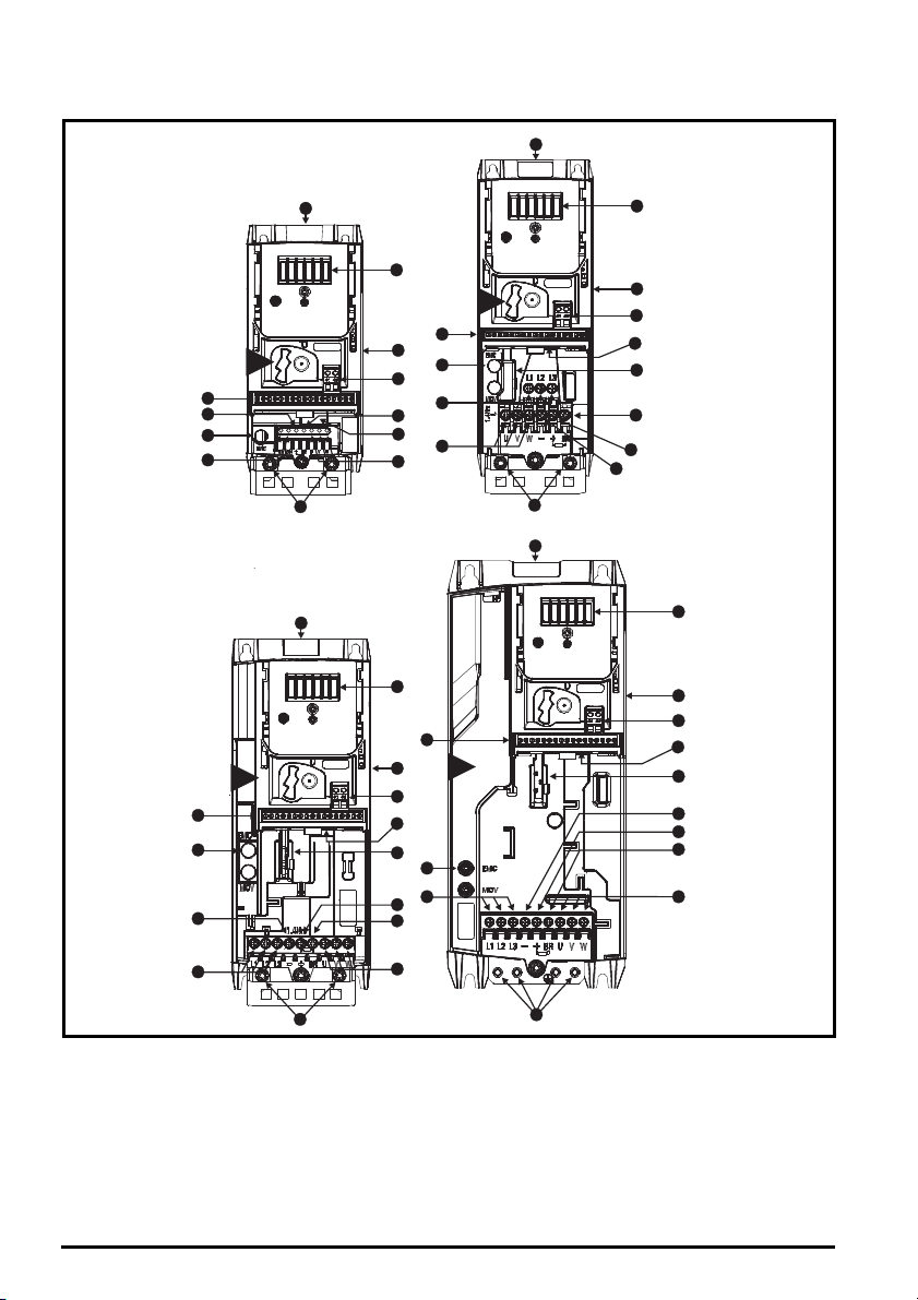
2.4 Drive features
10
5
8
7
7
11
6
4
1
9
9
4
1
3
6
8
2
2
2
2
4
4
1
10
8
6
6
3
3
5
7
11
1
8
11
9
5
11
10
12
12
12
12
10
5
7
14
14
13
13
14
13
14
13
3
4
2
1
Figure 2-3 Features of the drive (Unidrive M400 illustrated)
Key
1. Rating label (On side of
drive)
2. Identification label 6. Braking terminal 10. Motor connections 14. Keypad connection
3. Option module
connection
4. Relay connections 8. DC bus + 12. Ground connections
5. Control connections 9. DC bus - 13. Safe Torque Off
7. Internal EMC filter
screw
11. AC supply connections
connections
18 Unidrive M100 to M400 Frame 1 to 4 Power Installation Guide
Issue Number: 5
Page 19
Page 20
Page 21
3.2.2 Environmental protection
NOTE
The drive must be protected from:
• Moisture, including dripping water or spraying water and condensation. An anti-condensation
heater may be required, which must be switched off when the drive is running.
• Contamination with electrically conductive material
• Contamination with any form of dust which may restrict the fan, or impair airflow over various
components
• Temperature beyond the specified operating and storage ranges
• Corrosive gasses
During installation it is recommended that the vents on the drive are covered to prevent
debris (e.g. wire off-cuts) from entering the drive.
3.2.3 Cooling
The heat produced by the drive must be removed without its specified operating temperature being
exceeded. Note that a sealed enclosure gives much reduced cooling compared with a ventilated one,
and may need to be larger and/or use internal air circulating fans.
For further information, refer to section 3.5.1 Enclosure sizing on page 28.
3.2.4 Electrical safety
The installation must be safe under normal and fault conditions. Electrical installation instructions are
given in Chapter 4 Electrical installation on page 41.
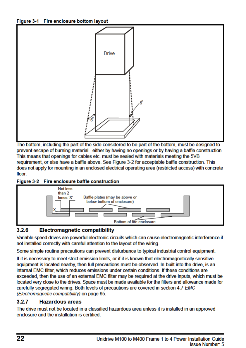
3.2.5 Fire protection
The drive enclosure is not classified as a fire enclosure. A separate fire enclosure must be provided.
For installation in the USA, a NEMA 12 enclosure is suitable.
For installation outside the USA, the following (based on IEC 62109-1, standard for PV inverters) is
recommended.
Enclosure can be metal and/or polymeric, polymer must meet requirements which can be
summarized for larger enclosures as using materials meeting at least UL 94 class 5VB at the point of
minimum thickness.
Air filter assemblies to be at least class V-2.
The location and size of the bottom shall cover the area shown in Figure 3-1. Any part of the side
which is within the area traced out by the 5° angle is also considered to be part of the bottom of the
fire enclosure.
Safety information Product information
Mechanical installation
Electrical installation Technical data UL listing information
Unidrive M100 to M400 Frame 1 to 4 Power Installation Guide 21
Issue Number: 5
Page 22
Page 23
Page 24
Page 25
Page 26
Page 27
Page 28

3.5.1 Enclosure sizing
A
e
P
kT
intText
–
-----------------------------------
=
NOTE
1. Add the dissipation figures from section 5.1.2 Power dissipation on page 81 for each drive that is
to be installed in the enclosure.
2. If an external EMC filter is to be used with each drive, add the dissipation figures from section
5.2.1 EMC filter ratings on page 101 for each external EMC filter that is to be installed in the
enclosure.
3. If the braking resistor is to be mounted inside the enclosure, add the average power figures for
each braking resistor that is to be installed in the enclosure.
4. Calculate the total heat dissipation (in Watts) of any other equipment to be installed in the
enclosure.
5. Add the heat dissipation figures obtained above. This gives a figure in Watts for the total heat that
will be dissipated inside the enclosure.
Calculating the size of a sealed enclosure
The enclosure transfers internally generated heat into the surrounding air by natural convection (or
external forced air flow); the greater the surface area of the enclosure walls, the better is the
dissipation capability. Only the surfaces of the enclosure that are unobstructed (not in contact with a
wall or floor) can dissipate heat.
Calculate the minimum required unobstructed surface area A
Where:
Unobstructed surface area in m2 (1 m2 = 10.9 ft2)
A
e
T
Maximum expected temperature in
ext
Maximum permissible temperature in oC inside the enclosure
T
int
o
C outside the enclosure
P Power in Watts dissipated by all heat sources in the enclosure
k Heat transmission coefficient of the enclosure material in W/m
Example
To calculate the size of an enclosure for the following:
• Two drives operating at the Normal Duty rating
• External EMC filter for each drive
• Braking resistors are to be mounted outside the enclosure
• Maximum ambient temperature inside the enclosure: 40 C
• Maximum ambient temperature outside the enclosure: 30 C
For example, if the power dissipation from each drive is 187 W and the power dissipation from each
external EMC filter is 9.2 W.
Total dissipation: 2 x (187 + 9.2) =392.4 W
for the enclosure from:
e
2/o
C
Power dissipation for the drives and the external EMC filters can be obtained from Chapter
5 Technical data on page 79.
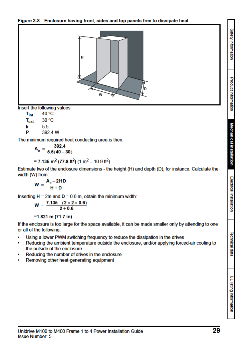
The enclosure is to be made from painted 2 mm (0.079 in) sheet steel having a heat transmission
coefficient of 5.5 W/m
2/o
C. Only the top, front, and two sides of the enclosure are free to dissipate
heat.
The value of 5.5 W/m
2
/ºC can generally be used with a sheet steel enclosure (exact values can be
obtained from the supplier of the material). If in any doubt, allow for a greater margin in the
temperature rise.
28 Unidrive M100 to M400 Frame 1 to 4 Power Installation Guide
Issue Number: 5
Page 29
Page 30

Calculating the air-flow in a ventilated enclosure
V
3kP
T
intText
–
---------------------------
=
P
o
P
l
-------
V
31.3 323.7
40 30–
---------------------------------------
=
The dimensions of the enclosure are required only for accommodating the equipment. The
equipment is cooled by the forced air flow.
Calculate the minimum required volume of ventilating air from:
Where:
V Air-flow in m
T
Maximum expected temperature in C outside the enclosure
ext
T
Maximum permissible temperature in C inside the enclosure
int
3
per hour (1 m3/hr = 0.59 ft3/min)
P Power in Watts dissipated by all heat sources in the enclosure
k Ratio of
Where:
P
is the air pressure at sea level
0
is the air pressure at the installation
P
I
Typically use a factor of 1.2 to 1.3, to allow also for pressure-drops in dirty air-filters.
Example
To calculate the size of an enclosure for the following:
• Three drives operating at the Normal Duty rating
• External EMC filter for each drive
• Braking resistors are to be mounted outside the enclosure
• Maximum ambient temperature inside the enclosure: 40 C
• Maximum ambient temperature outside the enclosure: 30 C
For example, dissipation of each drive: 101 W and dissipation of each external EMC filter: 6.9 W
(max).
Total dissipation: 3 x (101 + 6.9) = 323.7 W
Insert the following values:
T
40 C
int
T
30 C
ext
k 1.3
P 323.7 W
Then:
= 126.2 m
30 Unidrive M100 to M400 Frame 1 to 4 Power Installation Guide
3
/hr (74.5 ft3 /min) (1 m3/ hr = 0.59 ft3/min)
Issue Number: 5
Page 31

3.5.2 Enclosure design and drive ambient temperature
Drive derating is required for operation in high ambient temperatures
Totally enclosing or through panel mounting the drive in either a sealed cabinet (no airflow) or in a
well ventilated cabinet makes a significant difference on drive cooling.
The chosen method affects the ambient temperature value (T
) which should be used for any
rate
necessary derating to ensure sufficient cooling for the whole of the drive.
The ambient temperature for the four different combinations is defined below:
= T
1. Totally enclosed with no air flow (<2 m/s) over the drive T
2. Totally enclosed with air flow (>2 m/s) over the drive T
rate
rate
= T
3. Through panel mounted with no airflow (<2 m/s) over the drive T
T
int
4. Through panel mounted with air flow (>2 m/s) over the drive T
+ 5 °C
int
int
= the greater of T
rate
= the greater of T
rate
+5 °C, or
ext
or T
ext
int
Where:
= Temperature outside the cabinet
T
ext
= Temperature inside the cabinet
T
int
= Temperature used to select current rating from tables in Chapter 5 Technical data on
T
rate
page 79.
3.6 Heatsink fan operation
The drive is ventilated by an internal heatsink fan. The fan channels air through the heatsink
chamber.
Ensure the minimum clearances around the drive are maintained to allow air to flow freely.
The heatsink fan on all drive sizes is a variable speed fan (except for size 1 which has a single speed
fan). The drive controls the speed at which the fan runs based on the temperature of the heatsink
and the drive's thermal model system. The maximum speed at which the fan operates can be limited
in Pr 06.045. This could incur an output current derating.
Table 3-2 Environmental considerations
Environment Comments
Clean
Dry, dusty (non-conductive)
Dry, dusty (conductive)
Regular cleaning recommended
Safety information Product information
Mechanical installation
Electrical installation Technical data UL listing information
Unidrive M100 to M400 Frame 1 to 4 Power Installation Guide 31
Issue Number: 5
Page 32

3.7 External EMC filter
The external EMC filter details for each drive rating are provided in the table below.
Model CT part number
100 V
01100017 to 01100024
02100042 to 02100056 4200-2000 0.90 1.98
200 V
01200017 to 01200042
02200024 to 02200075
03200100
04200133 to 04200176
400 V
02400013 to 02400041
03400056 to 03400094
04400135 to 04400170
Mount the external EMC filter following the guidelines in section 4.7.5 Compliance with generic
emission standards on page 73
4200-1000
4200-1001 (low leakage)
4200-1000
4200-1001 (low leakage)
4200-2001
4200-2002 (low leakage)
4200-2003
4200-2004 (low leakage)
4200-3000
4200-3001 (low leakage)
4200-3004
4200-3005 (low leakage)
4200-4000
4200-4001 (low leakage)
4200-4002
4200-4003 (low leakage)
4200-2005
4200-2006 (low leakage)
4200-3008
4200-3009 (low leakage)
4200-4004
4200-4005 (low leakage)
Weight
kg lb
0.49 1.08
0.49 1.08
0.86 1.89
0.88 1.94
0.92 2.02
0.95 2.09
1.3 2.86
1.4 3.08
0.82 1.80
12.20
1.4 3.08
32 Unidrive M100 to M400 Frame 1 to 4 Power Installation Guide
Issue Number: 5
Page 33

Figure 3-9 Footprint mounting the EMC filter
Figure 3-10 Bookcase mounting the EMC filter
Safety information Product information
Mechanical installation
Electrical installation Technical data UL listing information
Unidrive M100 to M400 Frame 1 to 4 Power Installation Guide 33
Issue Number: 5
Page 34

Figure 3-11 Size 1 to 4 external EMC filter
W
C
A
X
X
Y
Y
V
B
H
Y
Y
D
Z
Z
V: Ground stud
Z: Bookcase mounting slot diameter CS: Cable size
Table 3-3 Size 1 external EMC filter dimensions
CT part
number
4200-1000
4200-1001
ABCDHWV/XYZCS
160 mm
(6.30 in)
198.8 mm
(7.83 in)
52.4 mm
(2.06 in)
Table 3-4 Size 2 external EMC filter dimensions
CT part
number
4200-2000
4200-2001
4200-2002
4200-2003
4200-2004
4200-2005
4200-2006
AB CDHWV/XYZCS
206 mm
(8.11 in)
244.8 mm
(9.64 in)
53.4 mm
(2.10 in)
X: Threaded holes for footprint
mounting of the drive
41 mm
(1.61 in)
41 mm
(1.61 in)
215 mm
(8.46 in)
261 mm
(10.2 in)
75 mm
(2.95 in)
78 mm
(3.07 in)
Y: Footprint mounting hole diameter
4.5 mm
M4
(0.18 in)
4.5 mm
M4
(0.18 in)
4.5 mm
(0.18 in)
4.5 mm
(0.18 in)
1.5 mm
(16 AWG)
4.0 mm
(12 AWG)
1.5 mm
(16 AWG)
2
2
2
34 Unidrive M100 to M400 Frame 1 to 4 Power Installation Guide
Issue Number: 5
Page 35

Table 3-5 Size 3 external EMC filter dimensions
CT part
number
4200-3000
4200-3001
4200-3004
4200-3005
4200-3008
4200-3009
ABCDHWV/XYZCS
227 mm
(8.94 in)
265.8 mm
(10.4 in)
59 mm
(2.32 in)
41 mm
(1.61 in)
282 mm
(11.1 in)
Table 3-6 Size 4 external EMC filter dimensions
CT part
number
4200-4000
4200-4001
4200-4002
4200-4003
4200-4004
4200-4005
ABCDHWV/XYZCS
279 mm
(10.9 in)
318.8 mm
(12.5 in)
80.5 mm
(3.17 in)
41 mm
(1.61 in)
334 mm
(13.1 in)
90 mm
(3.54 in)
115 mm
(4.53 in)
M4
M5
4.5 mm
(0.18 in)
5.5 mm
(0.22 in)
4.5 mm
(0.18 in)
5.5 mm
(0.22 in)
4.0 mm
(12 AWG)
2.5 mm
(14 AWG)
4.0 mm
(12 AWG)
2.5 mm
(14 AWG)
Safety information Product information
2
2
2
2
Mechanical installation
Electrical installation Technical data UL listing information
Unidrive M100 to M400 Frame 1 to 4 Power Installation Guide 35
Issue Number: 5
Page 36

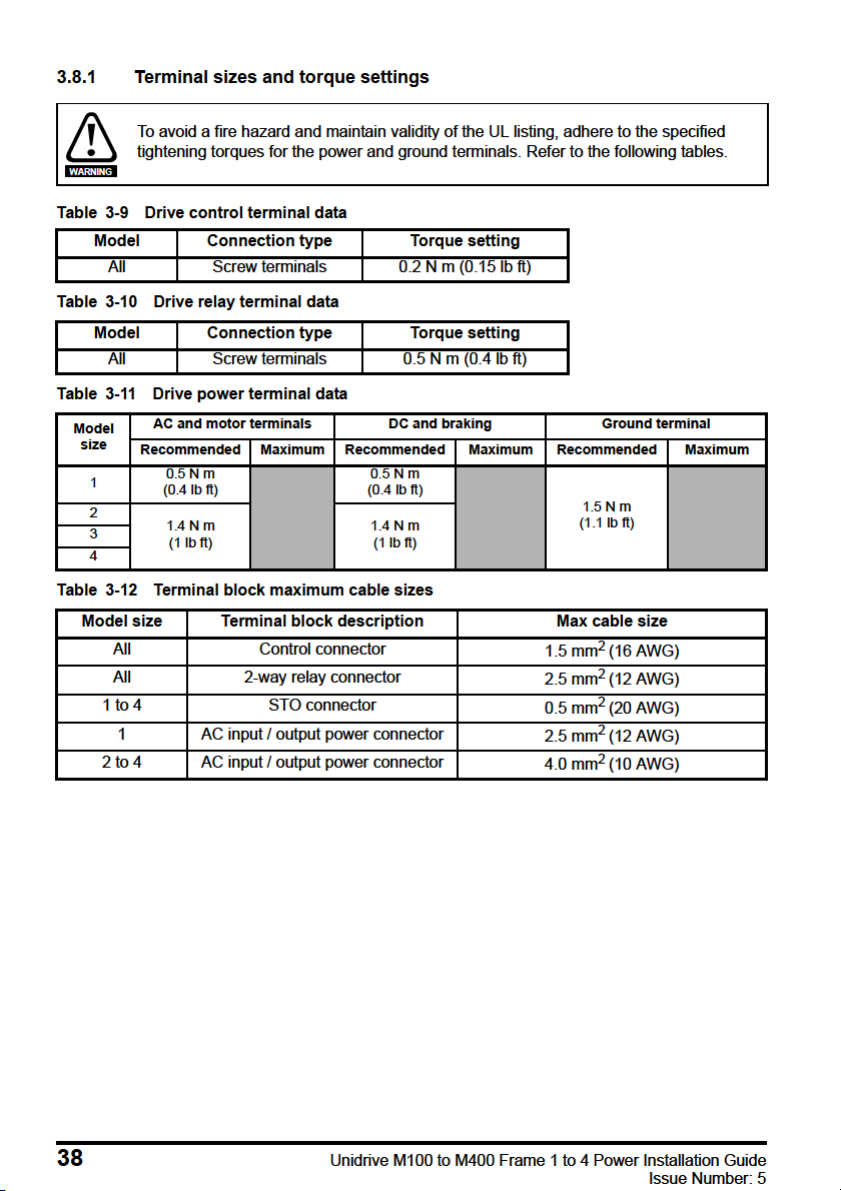
3.7.1 EMC filter torque settings
Table 3-7 Optional external EMC filter terminal data
CT part
number
Power connections Ground connections
Max cable
size
*
Max torque Ground stud size Max torque
4200-1000
4200-1001
4200-2000
4200-2001
10 mm
(6 AWG)
2
1.8 N m
(1.4 lb ft)
M4
4200-2002
4200-2003
4200-2004
4200-2005
6 mm
(8 AWG)
2
1.8 N m
(1.4 lb ft)
M4
4200-2006
4200-3000
4200-3001
4200-3004
4200-3005
4200-3008
4200-3009
10 mm
(6 AWG)
6 mm
(8 AWG)
6 mm
(8 AWG)
2
2
2
1.8 N m
(1.4 lb ft)
1.8 N m
(1.4 lb ft)
1.8 N m
(1.4 lb ft)
M4
M4
M4
4200-4000
4200-4001
4200-4002
4200-4003
6 mm
(8 AWG)
2
1.8 N m
(1.4 lb ft)
M5
4200-4004
4200-4005
* Flex wire.
Table 3-8 Fastener details for drive footprint mounting on external EMC filter
Type Size 1 Size 2 Size 3 Size 4
Thread size M4 M4 M4 M5
Length (mm) 12 12 12 12
1.7 N m
(1.3 lb ft)
1.7 N m
(1.3 lb ft)
1.7 N m
(1.3 lb ft)
1.7 N m
(1.3 lb ft)
1.7 N m
(1.3 lb ft)
2.2 N m
(1.6 lb ft)
36 Unidrive M100 to M400 Frame 1 to 4 Power Installation Guide
Issue Number: 5
Page 37

Page 38
Page 39

Page 40

Table 3-13 Heatsink fan replacement kits
Model Part number
Size 1 3470-0092
Size 2 3470-0095
Size 3 3470-0099
Size 4 3470-0103
40 Unidrive M100 to M400 Frame 1 to 4 Power Installation Guide
Issue Number: 5
Page 41

Page 42

Page 43

Page 44

Page 45

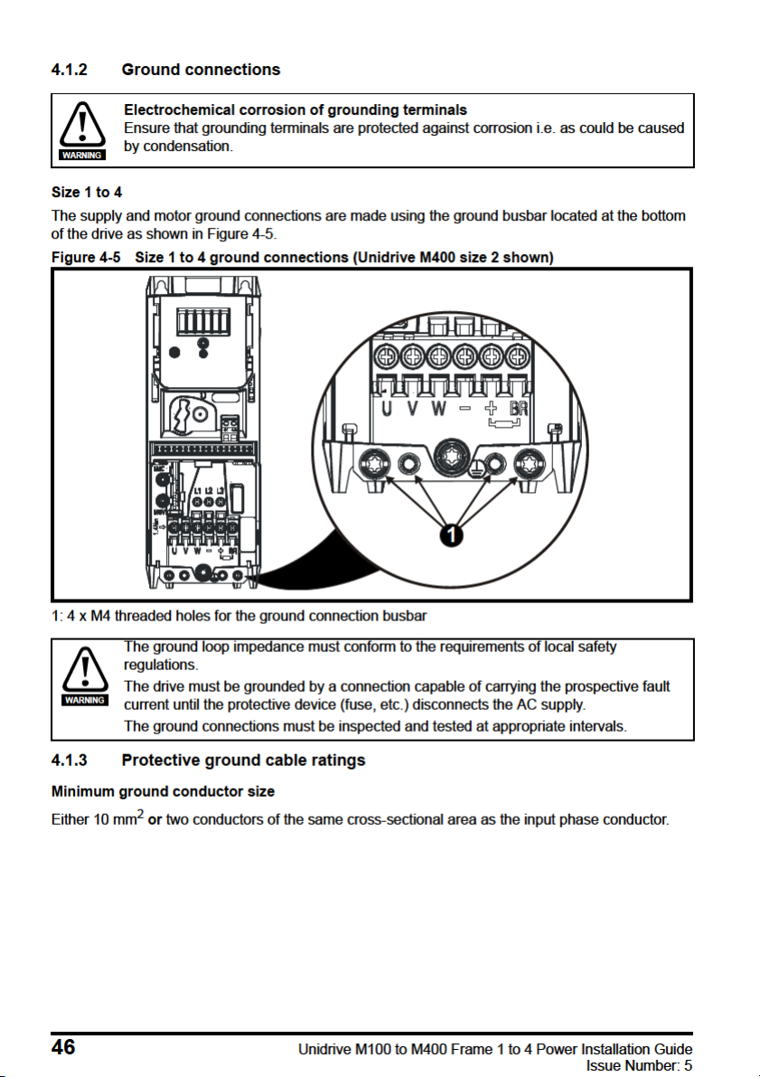
Page 46
Page 47

Page 48

Line reactors are particularly recommended for use with the following drive models when one of the
L
Y
100
----------
V
3
-------
1
2 f I
------------
=
above factors exists, or when the supply capacity exceeds 175 kVA: Size 1 to 3.
Model sizes 04200133 to 04400170 have an internal DC choke so they do not require AC line
reactors except for cases of excessive phase unbalance or extreme supply conditions.
When required, each drive must have its own reactor(s). Three individual reactors or a single threephase reactor should be used.
Reactor current ratings
The current rating of the line reactors should be as follows:
Continuous current rating:
Not less than the continuous input current rating of the drive
Repetitive peak current rating:
Not less than twice the continuous input current rating of the drive
4.2.3 Input inductor calculation
To calculate the inductance required (at Y %), use the following equation:
Where:
I = drive rated input current (A)
L = inductance (H)
f = supply frequency (Hz)
V = voltage between lines
Issue Number: 5
48 Unidrive M100 to M400 Frame 1 to 4 Power Installation Guide
Page 49

4.2.4 Input line reactor specification for size 1 to 4
Table 4-1 AC line reactor values
Drives
used with
01200017
01200024
01200033
01200042
02200024 4402-0224 1 2.25 6.5 13 0.8 72 65 90
02200033
02200056
02200075
03200100
04200133
04200176
02200024 4401-0224 3 1.96 4.3 8.6 1.1 65 110 70
02200033
02200042
02200056
02200075
03200100
04200176
02400013 4401-0232 3 6.1 2.4 4.8 1.1 65 110 70
02400018
02400023
02400032
02400041
03400056 4401-0149 3 1.62 9.1 18.2 1.8 156 70 125
03400073 4401-0234 3 1.12 13 26 2.5 156 72 114
03400094
04400135
04400170 4401-0235 3 0.71 21 42 3.6 156 68 133
Reactor
part
number
4402-0224 1 2.25 6.5 13 0.8 72 65 90
4402-0225 1 1.0 15.1 30.2 1.1 82 75 100
4402-0225 1 1.0 15.1 30.2 1.1 82 75 10002200042
4402-0226 1 0.5 26.2 52.4 1.5 82 90 105
4401-0225 3 1.12 7.5 15 1.2 80 130 65
4401-0143 3 0.79 13.5 27 1.8 156 70 125
4401-0144 3 0.48 20.6 41.2 2.4 156 80 12504200133
4401-0233 3 5.1 3.5 7 1.2 80 130 65
4401-0148 3 2.94 6.6 13.2 1.3 80 130 75
4401-0151 3 1.05 15.8 31.6 2.6 156 80 125
phases
Input
Inductance
mH A A kg
Continuous
rms
c ur r e n t
Peak
current
Weight
Dimensions
(mm)
LDH
mm mm mm
Safety information Product information Mechanical installation
Electrical installation
Technical data UL listing information
Unidrive M100 to M400 Frame 1 to 4 Power Installation Guide 49
Issue Number: 5
Page 50

Page 51

Page 52

Table 4-5 AC Input current and fuse ratings (100 V)
Class
gG
Fuse rating
Nominal Maximum
15 15
Class
CC, J or
T*
MCB
rating**
Nominal
15
Model
Maximum
continuous
input
current
AA
Maximum
overload
input
current
IEC UL
Maximum
AAAA
01100017 8.7 12.6 10
01100024 11.1 15.2 16 15 15 15
02100042 18.8 28.2 20 20 20 15
02100056 24.0 37.4 25 25 25 15
Table 4-6 AC Input current and fuse ratings (200 V)
Typical
Model
01200017 4.5 6.9 6
01200024 5.3 8.4 6 6 6 15
01200033
01200042 10.4 16.8 16 16 15 15 15
02200024 - / 3.2 5.3/4.1 8.1/5.9 6 6
02200033 - / 4.3 8.3/6.7 14/9.2 10 10 10 10 15
02200042 - / 5.4 10.4/7.5 16.4/10.8 16 10 16 10 15/10 15 10 15
02200056 - / 8.1 16.0/12.9 24.0/17.5
02200075 - / 9.1 18.1/13.5 30.4/19.5 20/15 15
03200100 - / 12.8 23.9/17.7 30/25 25 20 25 20
04200133 - / 13.5 23.7/16.9 43.3/23.5 25 20 25 20
04200176 - / 17.0 23.7/21.3 43.3/28.6 25 25 25 25 25 25 25 25
current
Maximum
continuous
input
input
current
AA AAAAA AAA AA
Maximum
overload
input
current
8.3 14.2 10 10 15 15 15
Nominal Maximum
1ph 3ph 1ph 3ph 1ph 3ph 1ph 3ph
20 16 20 16
IEC UL / USA
6
Fuse rating MCB
Maximum
66
666
20/15
20 15
25/20 25 20
25/20 25 20
Class
gG
gG
gG
gG
Nominal
Class
CC, J
or T*
CC,
J or
T*
CC,
J or
T*
CC,
J or
T*
rating
Nominal
15
15
15
25 20
25 20
**
* These are fast acting fuses.
** UL Listed DIVQ / DIVQ7 listed, rated voltage is 600 Vac (for USA and Canada). Short circuit rating
is 10 kA. In other countries, EN IEC circuit breakers can be used with 10 kA supply rating.
52 Unidrive M100 to M400 Frame 1 to 4 Power Installation Guide
Issue Number: 5
Page 53

Page 54

Table 4-9 Cable ratings (200 V)
NOTE
NOTE
Cable size (IEC 60364-5-52)
Model
01200017
01200024
01200033
01200042
02200024
02200033
02200042
02200056 2.5/1.5 12/14
02200075 2.5 12
03200100 4 4 1.5 4 10/12 10 14 10
04200133 4/2.5
04200176 4
Input Output Input Output
Nominal Maximum Nominal Maximum Nominal Maximum Nominal Maximum
1 2.5 1 2.5 16 12 16 12
1
2
mm
16
414
42.54 10 10 12 10
Cable size (UL508C)
AWG
10 16 10
Table 4-10 Cable ratings (400 V)
Cable size (IEC 60364-5-52)
Model
02400013
02400018
02400023
02400032
02400041
03400056 1
03400094 2.5 1.5 14
04400135 2.5
04400170 4
Input Output Input Output
Nominal Maximum Nominal Maximum Nominal Maximum Nominal Maximum
141 416101610
2
mm
4
42.54 101012 10
1
4
14
12
Cable size (UL508C)
AWG
10
16
1003400073 1.5
PVC insulated cable should be used.
Cable sizes are from IEC60364-5-52:2001 table A.52.C with correction factor for 40°C
ambient of 0.87 (from table A52.14) for cable installation method B2 (multicore cable in
conduit).
Installation class (ref: IEC60364-5-52:2001)
B1 - Separate cables in conduit.
B2 - Multicore cable in conduit.
C - Multicore cable in free air.
Cable size may be reduced if a different installation method is used, or if the ambient temperature is
lower.
54 Unidrive M100 to M400 Frame 1 to 4 Power Installation Guide
Issue Number: 5
Page 55

Page 56

4.4.1 Cable types and lengths
Since capacitance in the motor cable causes loading on the output of the drive, ensure the cable
length does not exceed the values given in Table 4-11 to Table 4-13.
Use 105 °C (221 °F) (UL 60/75 °C temp rise) PVC-insulated cable with copper conductors having a
suitable voltage rating, for the following power connections:
• AC supply to external EMC filter (when used)
• AC supply (or external EMC filter) to drive
• Drive to motor
• Drive to braking resistor
Table 4-11 Maximum motor cable lengths (100 V drives)
100 V Nominal AC supply voltage
Model
01100017
01100024
02100042
02100056
Table 4-12 Maximum motor cable lengths (200 V drives)
Model
01200017
01200024
01200033
01200042
02200024
02200033
02200042
02200056
02200075
03200100 100 m (330 ft)
04200133
04200176
Maximum permissible motor cable length for each of the following switching frequencies
0.667 kHz 1kHz 2 kHz 3 kHz 4 kHz 6 kHz 8 kHz 12 kHz 16 kHz
kHz
37.5 m
(122 ft)
75 m
(245 ft)
3
kHz
37.5 m
(122 ft)
75 m
(245 ft)
75 m
(245 ft)
75 m
(245 ft)
75 m (245 ft)
100 m (330 ft)
200 V Nominal AC supply voltage
Maximum permissible motor cable length for each of the following switching frequencies
0.667
kHz
1
kHz
75 m (245 ft)
100 m (330 ft)
100 m (330 ft)
kHz
2
25 m
50 m
6
kHz
25 m
50 m
(165 ft)
50 m
(165 ft)
50 m
(165 ft)
18.75 m
(61.9 ft)
37.5 m
(122 ft)
18.75 m
(61 ft)
37.5 m
(122 ft)
37.5 m
(122 ft)
37.5 m
(122 ft)
(82.5 ft)
(165 ft)
4
(82.5 ft)
8
kHz
12.5 m
(41.25 ft)
25 m
(82.5 ft)
12
kHz16kHz
12.5 m
(41 ft)
25 m
(82.5 ft)
25 m
(82.5 ft)
25 m
(82.5 ft)
9 m
(29.7 ft)
18 m
(59.4ft)
9 m
(30 ft)
18 m
(60 ft)
18 m
(60 ft)
18 m
(60 ft)
56 Unidrive M100 to M400 Frame 1 to 4 Power Installation Guide
Issue Number: 5
Page 57

Page 58

Page 59

Page 60
Page 61

Page 62

Table 4-17 Braking resistor resistance and power rating (400 V)
Model
02400013
02400018 0.55
02400023 0.75
02400032 1.1
02400041 1.5
03400056
03400073 3
03400094 4
04400135
04400170 7.5
* Resistor tolerance: ±10 %
For high-inertia loads or under continuous braking, the continuous power dissipated in the braking
resistor may be as high as the power rating of the drive. The total energy dissipated in the braking
resistor is dependent on the amount of energy to be extracted from the load.
The instantaneous power rating refers to the short-term maximum power dissipated during the on
intervals of the pulse width modulated braking control cycle. The braking resistor must be able to
withstand this dissipation for short intervals (milliseconds). Higher resistance values require
proportionately lower instantaneous power ratings.
In most applications, braking occurs only occasionally. This allows the continuous power rating of the
braking resistor to be much lower than the power rating of the drive. It is therefore essential that the
instantaneous power rating and energy rating of the braking resistor are sufficient for the most
extreme braking duty that is likely to be encountered.
Optimization of the braking resistor requires careful consideration of the braking duty.
Select a value of resistance for the braking resistor that is not less than the specified minimum
resistance. Larger resistance values may give a cost saving, as well as a safety benefit in the event
of a fault in the braking system. Braking capability will then be reduced, which could cause the drive
to trip during braking if the value chosen is too large.
Thermal protection circuit for the braking resistor
The thermal protection circuit must disconnect the AC supply from the drive if the resistor becomes
overloaded due to a fault. Figure 4-11 shows a typical circuit arrangement.
Minimum
resistance*
Ω
270 2.2
100 6.0
50 11.2
Instantaneous
power rating
kW
Continuous
power rating
kW
0.37
2.2
5.5
62 Unidrive M100 to M400 Frame 1 to 4 Power Installation Guide
Issue Number: 5
Page 63

Page 64

Page 65

Page 66

Page 67

Page 68

Page 69

Page 70

Page 71

Page 72

Page 73

Page 74

Page 75

Page 76

Page 77

Page 78

Figure 4-28 Surge suppression for analog and bipolar inputs and outputs
Signal from plant Signal to drive
0V 0V
2 x 15V zener diode
e.g. 2xBZW50-15
Surge suppression devices are available as rail-mounting modules, e.g. from Phoenix Contact:
Unipolar TT-UKK5-D/24 DC
Bipolar TT-UKK5-D/24 AC
These devices are not suitable for encoder signals or fast digital data networks because the
capacitance of the diodes adversely affects the signal. Most encoders have galvanic isolation of the
signal circuit from the motor frame, in which case no precautions are required. For data networks,
follow the specific recommendations for the particular network.
78 Unidrive M100 to M400 Frame 1 to 4 Power Installation Guide
Issue Number: 5
Page 79

5 Technical data
5.1 Drive technical data
5.1.1 Power and current ratings (Derating for switching frequency and
temperature)
For a full explanation of ‘Normal Duty’ and ‘Heavy Duty’ refer to the Control User Guide.
Table 5-1 Maximum permissible continuous output current @ 40 °C (104 °F) ambient
Heavy Duty
Model
100 V
01100017 0.25 0.33 1.7
01100024 0.37 0.5 2.4
02100042 0.75 1.0 4.2
02100056 1.1 1.5 5.6
200 V
01200017 0.25 0.33 1.7
01200024 0.37 0.5 2.4
01200033 0.55 0.75 3.3
01200042 0.75 1.0 4.2
02200024 0.37 0.5 2.4
02200033 0.55 0.75 3.3
02200042 0.75 1.0 4.2
02200056 1.1 1.5 5.6
02200075 1.5 2.0 7.5 7.0
03200100 2.2 3.0 10 9 7.3
04200133 3.0 3.0 13.3
04200176 4.0 5.0 17.6 17.0
400 V
02400013 0.37 0.5 1.3 1.3 1.3 1.3 1.3 1.3 1.3 1.3
02400018 0.55 0.75 1.8 1.8 1.8 1.8 1.8 1.8 1.8 1.8
02400023 0.75 1.0 2.3 2.3 2.3 2.3 2.3 2.3 2.3 2.0
02400032 1.1 1.5 3.2 3.2 3.2 3.2 3.2 3.2 3.2 2.0
02400041 1.5 2.0 4.1 4.1 4.1 4.1 4.1 4.1 3.8 2.0
03400056 2.2 3.0 5.6 5.6 5.6 5.6 5.6 5.6 5.1 3.7 2.4
03400073 3.0 3.0 7.3 7.3 7.3 7.3 7.3 7.1 5.6 3.8
03400094 4.0 5.0 9.4 9.4 9.4 9.4 9.4 8.5 7 4.6
04400135 5.5 7.5 13.5 10.7
04400170 7.5 10.0 17 13.5 10.7
Nominal
rating
kW hp
Maximum permissible continuous output current (A) for the following
0.667
kHz1kHz2kHz3kHz4kHz6kHz8kHz12kHz
switching frequencies
16
kHz
Safety information Product information Mechanical installation Electrical installation
Technical data
UL listing information
Unidrive M100 to M400 Frame 1 to 4 Power Installation Guide 79
Issue Number: 5
Page 80

Table 5-2 Maximum permissible continuous output current @ 50 °C (122 °F) (size 1 to 4)
NOTE
Heavy Duty
Model
0.667
kHz
100 V
01100017* 1.7
01100024* 2.4
02100042 4.2
02100056 5.6 5.5 5.3 5.1 4.9
200 V
01200017* 1.7
01200024* 2.4
01200033* 3.3
01200042* 4.2
02200024 2.4
02200033 3.3
02200042 4.2 4.0
02200056 5.6 5.6 5.6 5.6 5.6 5.6 5.6 5.6 5.4
02200075 7.5 7.5 7.4 7.2 6.8 6.6 6.3 5.8 5.4
03200100 10 10 10 10 9.5 8.6 7.5 6.1 5
04200133 13.3
04200176 17.6 17 15.5
400 V
02400013 1.3 1.3 1.3 1.3 1.3 1.3 1.3 1.1
02400018 1.8 1.8 1.8 1.8 1.8 1.8 1.8 1.1
02400023 2.3 2.3 2.3 2.3 2.3 2.3 2.3 1.1
02400032 3.2 3.2 3.2 3.2 3.2 3.2 2.5 1.1
02400041 4.1 4.1 4.1 4.1 3.7 3.2 2.5 1.1
03400056 5.6 5.6 5.6 5.6 5 3.5 2.8 1.9
03400073 7.3 7.3 7.3 7.3 6.2 4.5 3.4
03400094 9.4 9.4 9.4 9.4 7.9 6.2 4.7
04400135 13.5 12 9.3
04400170 17 15.3 15.2 12 9.3
Maximum permissible continuous output current (A)
for the following switching frequencies
1
kHz
2
kHz3kHz4kHz6kHz
8
kHz
12
kHz
16
kHz
* CI-Keypad not installed.
Ratings at 55 C are available on request.
80 Unidrive M100 to M400 Frame 1 to 4 Power Installation Guide
Issue Number: 5
Page 81

5.1.2 Power dissipation
Table 5-3 Losses @ 40 °C (104 °F) ambient (size 1 to 4)
Heavy Duty
Model
100 V
01100017 0.25 0.33 23 23 24 24 25 27 28 32 35
01100024 0.37 0.5 27 27 29 30 31 33 35 39 44
02100042 0.75 1.0 39 40 41 42 43 45 47 51 55
02100056 1.1 1.5 51 51 53 54 55 58 61 67 73
200 V
01200017 0.25 0.33 21 21 22 22 23 25 27 30 33
01200024 0.37 0.5 24 25 26 27 28 30 33 37 41
01200033 0.55 0.75 31 32 33 35 36 39 42 47 53
01200042 0.75 1.0 38 39 40 42 44 47 51 58 65
02200024 0.37 0.5 25 25 25 26 26 28 29 31 33
02200033 0.55 0.75 32 33 33 34 35 36 38 41 44
02200042 0.75 1.0 39 40 41 42 43 45 47 51 55
02200056 1.1 1.5 46 47 48 50 51 54 57 63 69
02200075 1.5 2.0 62 62 65 67 69 73 77 86 87
03200100 2.2 3.0 85 87 91 96 101 110 117 121 117
04200133
04200176 4.0 5.0 149 150 156 161 166 176 186 207 220
400 V
02400013 0.37 0.5 25 26 30 33 36 42 48 60
02400018 0.55 0.75 29 30 34 37 40 47 53 67
02400023 0.75 1.0 33 34 38 41 45 52 59 69
02400032 1.1 1.5 41 42 46 50 54 63 71 70
02400041 1.5 2.0 49 50 55 60 64 74 78 70
03400056 2.2 3.0 55 57 62 68 75 86 90 86 77
03400073 3.0 3.0 72 74 82 90 98 113 101 92
03400094 4.0 5.0 95 99 108 116 129 128 125 113
04400135 5.5 7.5 142 146 159 172 169 196 239 294 292
04400170 7.5 10.0 165 170 186 202 218 251 284 294 292
Nominal rating
kW hp
3.0 3.0 101 102 106 110 114 121 129 144 160
*
Drive losses (W) taking into account any current derating for the given
0.667
kHz1kHz2kHz3kHz4kHz6kHz8kHz12kHz16kHz
conditions
Safety information Product information Mechanical installation Electrical installation
Technical data
UL listing information
* Different losses with single-phase supply (available on request).
Unidrive M100 to M400 Frame 1 to 4 Power Installation Guide 81
Issue Number: 5
Page 82

Table 5-4 Losses @ 50°C (122°F) ambient (size 1 to 4)
Heavy Duty
Model
100 V
01100017 0.25 0.33 23 23 24 24 25 27 28 32 35
01100024 0.37 0.5 27 27 29 30 31 33 35 39 44
02100042 0.75 1.0 34 34 35 36 37 39 41 46 50
02100056 1.1 1.5 42 43 44 46 47 49 47 47 57
200 V
01200017 0.25 0.33 21 21 22 22 23 25 27 30 33
01200024 0.37 0.5 24 25 26 27 28 30 33 37 41
01200033 0.55 0.75 31 32 33 35 36 39 42 47 53
01200042 0.75 1.0 38 39 40 42 44 47 51 58 65
02200024 0.37 0.5 24 24 24 25 25 26 27 30 32
02200033 0.55 0.75 31 31 32 33 34 35 37 40 43
02200042 0.75 1.0 37 37 38 39 39 40 42 45 46
02200056 1.1 1.5 44 44 46 46 47 48 44 46 50
02200075 1.5 2.0 44 44 45 46 47 48 44 46 50
03200100 2.2 3.0 86 88 92 96 96 97 93 90 86
04200133 3.0 3.0 101 102 106 110 114 121 129 144 160
04200176 4.0 5.0 149 150 156 161 166 176 186 199 199
400 V
02400013 0.37 0.5 25 26 30 33 36 42 48 58
02400018 0.55 0.75 29 30 34 37 40 47 53 58
02400023 0.75 1.0 33 34 38 41 45 52 59 58
02400032 1.1 1.5 41 42 46 50 54 63 62 70
02400041 1.5 2.0 49 50 55 60 60 63 62 58
03400056 2.2 3.0 57 58 64 70 73 63 60 60
03400073 3.0 3.0 73 75 82 91 87 77 71
03400094 4.0 5.0 96 98 109 122 111 104 97
04400135 5.5 7.5 142 146 159 172 169 196 239 260 263
04400170 7.5 10.0 165 170 186 202 202 206 260 260 263
Nominal
rating
kW hp 0.667 kHz 1 kHz 2 kHz 3 kHz 4 kHz 6 kHz 8 kHz 12 kHz 16 kHz
Drive losses (W) taking into account any current derating for the given
conditions
82 Unidrive M100 to M400 Frame 1 to 4 Power Installation Guide
Issue Number: 5
Page 83

5.1.3 Supply requirements
AC supply voltage:
100 V drive: 100 V to 120 V ±10 %
200 V drive: 200 V to 240 V ±10 %
400 V drive: 380 V to 480 V ±10 %
Maximum supply imbalance: 2 % negative phase sequence (equivalent to 3 % voltage imbalance
between phases).
Frequency range: 45 to 66 Hz
For UL compliance only, the maximum supply symmetrical fault current must be limited to 100 kA
5.1.4 Line reactors
Input line reactors reduce the risk of damage to the drive resulting from poor phase balance or
severe disturbances on the supply network.
Where line reactors are to be used, reactance values of approximately 2 % are recommended.
Higher values may be used if necessary, but may result in a loss of drive output (reduced torque at
high speed) because of the voltage drop.
For all drive ratings, 2 % line reactors permit drives to be used with a supply unbalance of up to 3.5 %
negative phase sequence (equivalent to 5 % voltage imbalance between phases).
Severe disturbances may be caused by the following factors, for example:
• Power factor correction equipment connected close to the drive.
• Large DC drives having no or inadequate line reactors connected to the supply.
• Across the line (DOL) started motor(s) connected to the supply such that when any of these
motors are started, the voltage dip exceeds 20 %
Such disturbances may cause excessive peak currents to flow in the input power circuit of the drive.
This may cause nuisance tripping, or in extreme cases, failure of the drive.
Drives of low power rating may also be susceptible to disturbance when connected to supplies with a
high rated capacity.
Line reactors are particularly recommended for use with the following drive models when one of the
above factors exists, or when the supply capacity exceeds 175 kVA: Size 1 to 3
Model sizes 04200133 to 04400170 have an internal DC choke so they do not require AC line
reactors except for cases of excessive phase unbalance or extreme supply conditions.
When required, each drive must have its own reactor(s). Three individual reactors or a single threephase reactor should be used.
Reactor current ratings
The current rating of the line reactors should be as follows:
Continuous current rating:
Not less than the continuous input current rating of the drive
Repetitive peak current rating:
Not less than twice the continuous input current rating of the drive
The recommended AC line reactors are shown in section 4.2.4 Input line reactor specification for size
1 to 4 on page 49.
5.1.5 Motor requirements
No. of phases: 3
Maximum voltage:
200 V drive: 240 V
400 V drive: 480 V
Safety information Product information Mechanical installation Electrical installation
Technical data
UL listing information
Unidrive M100 to M400 Frame 1 to 4 Power Installation Guide 83
Issue Number: 5
Page 84

5.1.6 Temperature, humidity and cooling method
Size 1 to 4:
Ambient temperature operating range:
- 20 °C to 60 °C (- 4 °F to 140 °F).
Output current derating must be applied at ambient temperatures >40 °C (104 °F).
Cooling method: Forced convection
Maximum humidity: 95 % non-condensing at 40 °C (104 °F)
5.1.7 Storage
Size 1 to 4:
-40 °C (-40 °F) to +60 °C (140 °F) for long term storage.
Storage time is 2 years.
Electrolytic capacitors in any electronic product have a storage period after which they require
reforming or replacing.
The DC bus capacitors have a storage period of 10 years.
The low voltage capacitors on the control supplies typically have a storage period of 2 years and are
thus the limiting factor.
Low voltage capacitors cannot be reformed due to their location in the circuit and thus may require
replacing if the drive is stored for a period of 2 years or greater without power being applied.
It is therefore recommended that drives are powered up for a minimum of 1 hour after every 2 years
of storage.
This process allows the drive to be stored for a further 2 years.
5.1.8 Altitude
Altitude range: 0 to 3,000 m (9,900 ft), subject to the following conditions:
1,000 m to 3,000 m (3,300 ft to 9,900 ft) above sea level: de-rate the maximum output current
from the specified figure by 1% per 100 m (330 ft) above 1,000 m (3,300 ft)
For example at 3,000 m (9,900 ft) the output current of the drive would have to be de-rated by 20 %.
5.1.9 IP / UL Rating
The drive is rated to IP20 pollution degree 2 (non-conductive contamination only).
In addition to this, drives are rated to IP21 standard (without an Adaptor Interface module installed).
The IP rating of a product is a measure of protection against ingress and contact to foreign bodies
and water. It is stated as IP XX, where the two digits (XX) indicate the degree of protection provided
as shown in Table 5-5.
84 Unidrive M100 to M400 Frame 1 to 4 Power Installation Guide
Issue Number: 5
Page 85
Table 5-5 IP Rating degrees of protection
First digit Second digit
Protection against foreign bodies and access to
hazardous parts
Protection against ingress of water
0 Non-protected 0 Non-protected
Protected against solid foreign objects of
1
50 mm and greater
(back of a hand)
Protected against solid foreign objects of
2
12.5 mm and greater
(finger)
Protected against solid foreign objects of
3
2.5 mm and greater (tool)
Protected against solid foreign objects of
4
1.0 mm and greater (wire)
Protected against vertically falling water
1
drops
Protected against vertically falling water
2
drops when enclosure tilted up to 15 °
3 Protected against spraying water
4 Protected against splashing water
5 Dust-protected (wire) 5 Protected against water jets
6 Dust-tight (wire) 6 Protected against powerful water jets
7- 7
8- 8
Protected against the effects of temporary
immersion in water
Protected against the effects of continuous
immersion in water
Table 5-6 UL enclosure ratings
UL rating Description
Type 1
Type 12
Enclosures are intended for indoor use, primarily to provide a degree of
protection against limited amounts of falling dirt.
Enclosures are intended for indoor use, primarily to provide a degree of
protection against dust, falling dirt and dripping non-corrosive liquids.
Safety information Product information Mechanical installation Electrical installation
5.1.10 Corrosive gasses
Concentrations of corrosive gases must not exceed the levels given in:
• Table A2 of EN 50178:1998
Printed Circuit Board & Component Solder technology of M100-400 are conformal coated to survive
environments as described by IEC60721-3-3 3C3 and EN60068-2-60 Meth. 4. This corresponds to
the levels typical of urban areas with industrial activities and/or heavy traffic and in the immediate
neighborhood of industrial sources with chemical emissions.
5.1.11 RoHS compliance
The drive meets EU directive 2011/65/EU for RoHS compliance.
Unidrive M100 to M400 Frame 1 to 4 Power Installation Guide 85
Issue Number: 5
Technical data
UL listing information
Page 86

5.1.12 Vibration
Bump Test
Testing in each of three mutually perpendicular axes in turn.
Referenced standard: IEC 60068-2-27: Test Ea:
Severity: 15 g peak, 11 ms pulse duration, half sine.
No. of Bumps: 18 (3 in each direction of each axis).
Referenced standard: IEC 60068-2-29: Test Eb:
Severity: 18 g peak, 6 ms pulse duration, half sine.
No. of Bumps: 600 (100 in each direction of each axis).
Random Vibration Test
Testing in each of three mutually perpendicular axes in turn.
Referenced standard: IEC 60068-2-64: Test Fh:
Severity: 1.0 m²/s³ (0.01 g²/Hz) ASD from 5 to 20 Hz
Duration: 30 minutes in each of 3 mutually perpendicular axes.
Sinusoidal Vibration Test
Testing in each of three mutually perpendicular axes in turn.
Referenced standard: IEC 60068-2-6: Test Fc:
Frequency range: 5 to 500 Hz
Severity: 3.5 mm peak displacement from 5 to 9 Hz
Sweep rate:1 octave/minute
Duration: 15 minutes in each of 3 mutually perpendicular axes.
Referenced standard: EN 61800-5-1: 2007, Section 5.2.6.4. referring to IEC 60068-2-6:
Frequency range: 10 to 150 Hz
Severity: 0.075 mm amplitude from 10 to 57 Hz
Sweep rate:1 octave/minute
Duration:10 sweep cycles per axis in each of 3 mutually perpendicular axes.
Testing to Environmental Category ENV3
Subjected to resonance search in the range listed. If no natural frequencies found then subjected
only to endurance test.
Referenced standard: Environment Category ENV3:
Frequency range: 5 to 13.2 Hz ± 1.0 mm
For more information, please refer to section 12 Vibration Test 1 of the Lloyds Register Test
Specification Number 1.
5.1.13 Starts per hour
By electronic control: unlimited
By interrupting the AC supply: 20 (equally spaced)
-3 db/octave from 20 to 200 Hz
10 m/s² peak acceleration from 9 to 200 Hz
15 m/s² peak acceleration from 200 to 500 Hz
1g peak acceleration from 57 to 150 Hz
13.2 to 100 Hz ± 0.7g (6.9 ms -2)
5.1.14 Start up time
This is the time taken from the moment of applying power to the drive, to the drive being ready to run
the motor: 1.5 s
86 Unidrive M100 to M400 Frame 1 to 4 Power Installation Guide
Issue Number: 5
Page 87

5.1.15 Output frequency / speed range
Unidrive Mxxx models:
In all operating modes (Open loop, RFC-A) the maximum output frequency is limited to 550 Hz.
Unidrive HS30 models:
In open loop mode only, the maximum achievable output frequency is 3,000 Hz.
5.1.16 Accuracy and resolution
Frequency:
The absolute frequency accuracy depends on the accuracy of the oscillator used with the drive
microprocessor. The accuracy of the oscillator is ± 0.02 %, and so the absolute frequency accuracy
is ± 0.02 % of the reference, when a preset frequency is used. If an analog input is used, the absolute
accuracy is further limited by the absolute accuracy of the analog input.
The following data applies to the drive only; it does not include the performance of the source of the
control signals.
Open & closed loop resolution:
Preset frequency reference: 0.01 Hz
Analog input 1: 11 bit plus sign
Analog input 2: 11 bit
Current:
The resolution of the current feedback is 10 bit plus sign.
Accuracy: typical 2 %
worst case 5 %
5.1.17 Acoustic noise
The heatsink fan generates the majority of the sound produced by the drive. The heatsink fan on all
drives is a variable speed fan (except size 1, which is a single speed fan). The drive controls the speed
at which the fan runs based on the temperature of the heatsink and the drive's thermal model system.
Table 5-7 gives the sound pressure level at 1 m produced by the drive for the heatsink fan running at
the maximum and minimum speeds.
Table 5-7 Acoustic noise data
Size
1* 46.7 N/A
24542
3 58.6 49
45848
* Single speed fan.
Max speed
dBA
Min speed
dBA
Safety information Product information Mechanical installation Electrical installation
Technical data
Unidrive M100 to M400 Frame 1 to 4 Power Installation Guide 87
Issue Number: 5
UL listing information
Page 88

Page 89

Table 5-11 AC Input current and fuse ratings (100 V)
Class
gG
Fuse rating
Nominal Maximum
15 15
Class
CC, J
or T*
MCB
rating**
Nominal
15
Maximum
overload
input
current
Maximum
AA
IEC UL
AAAA
Model
Maximum
continuous
input
current
01100017 8.7 12.6 10
01100024 11.1 15.2 16 15 15 15
02100042 18.8 28.2 20 20 20 15
02100056 24.0 37.4 25 25 25 15
Table 5-12 AC Input current and fuse ratings (200 V)
Typ ic al
Model
01200017
01200024 5.3 8.4 6 6 6 15
01200033 8.3 14.2 10 10 15 15 15
01200042 10.4 16.8 16 16 15 15 15
02200024 - / 3.2 5.3/4.1 8.1/5.9 6 6
02200033 - / 4.3 8.3/6.7 14/9.2 10 10 10 10 15
02200042 - / 5.4 10.4/7.5 16.4/10.8 16 10 16 10 15/10 15 10 15
02200056 - / 8.1 16.0/12.9 24.0/17.5
02200075 - / 9.1 18.1/13.5 30.4/19.5 20/15 15
03200100 - / 12.8 23.9/17.7 30/25 25 20 25 20
04200133 - / 13.5 23.7/16.9 43.3/23.5 25 20 25 20
04200176 - / 17.0 23.7/21.3 43.3/28.6 25 25 25 25 25 25 25 25
current
Maximum
continuous
input
input
current
AA AAAAA AAA AA
Maximum
overload
input
current
4.5 6.9 6
IEC UL / USA
Nominal Maximum
1ph 3ph 1ph 3ph 1ph 3ph 1ph 3ph
6
20 16 20 16
Fuse rating MCB
Maximum
66
666
20/15
20 15
25/20 25 20
25/20 25 20
Class
gG
gG
gG
gG
Nominal
Class
CC, J
or T*
CC,
J or
T*
CC,
J or
T*
CC,
J or
T*
rating**
Nominal
15
15
15
25 20
25 20
* These are fast acting fuses.
** UL Listed DIVQ / DIVQ7 listed, rated voltage is 600 Vac (for USA and Canada). Short circuit rating
is 10 kA. In other countries, EN IEC circuit breakers can be used with 10 kA supply rating.
Safety information Product information Mechanical installation Electrical installation
Technical data
Unidrive M100 to M400 Frame 1 to 4 Power Installation Guide 89
Issue Number: 5
UL listing information
Page 90

Page 91

Table 5-15 Cable ratings (200 V)
NOTE
Cable size (IEC 60364-5-52)
Model
01200017
01200024
01200033
01200042
02200024
02200033
02200042
02200056 2.5/1.5 12/14
02200075 2.5 12
03200100 4 4 1.5 4 10/12 10 14 10
04200133 4/2.5
04200176 4
Input Output Input Output
Nominal Maximum Nominal Maximum Nominal Maximum Nominal Maximum
1 2.5 1 2.5 16 12 16 12
1
2
mm
16
414
42.54 10 10 12 10
Cable size (UL508C)
AWG
10 16 10
Table 5-16 Cable ratings (400 V)
Cable size (IEC 60364-5-52)
Model
02400013
02400018
02400023
02400032
02400041
03400056 1
03400094 2.5 1.5 14
04400135 2.5
04400170 4
Input Output Input Output
Nominal Maximum Nominal Maximum Nominal Maximum Nominal Maximum
141 416101610
2
mm
4
42.54 101012 10
1
4
14
12
Cable size (UL508C)
AWG
10
16
Safety information Product information Mechanical installation Electrical installation
1003400073 1.5
Technical data
PVC insulated cable should be used.
5.1.21 Protective ground cable ratings
Minimum ground conductor size
2
Either 10 mm
Unidrive M100 to M400 Frame 1 to 4 Power Installation Guide 91
Issue Number: 5
or two conductors of the same cross-sectional area as the input phase conductor.
UL listing information
Page 92

Table 5-17 Inrush current
Model Peak Inrush Current (A)
01100017 8.5
01100024 8.5
01200017 17
01200024 17
01200033 17
01200042 17
02100042 28.3
02100056 28.3
02200024 27.5
02200033 27.5
02200042 27.5
02200056 27.5
02200075 27.5
02400013 17
02400018 17
02400023 17
02400032 17
02400041 17
03200100 18.3
03400056 11.3
03400073 11.3
03400094 11.3
04200133 18.3
04200176 18.3
04400135 11.3
04400170 11.3
92 Unidrive M100 to M400 Frame 1 to 4 Power Installation Guide
Issue Number: 5
Page 93

5.1.22 Maximum motor cable lengths
Table 5-18 Maximum motor cable lengths (100 V drives)
100 V Nominal AC supply voltage
Model
01100017
01100024
02100042
02100056
Table 5-19 Maximum motor cable lengths (200 V drives)
Model
01200017
01200024
01200033
01200042
02200024
02200033
02200042
02200056
02200075
03200100 100 m (330 ft)
04200133
04200176
Maximum permissible motor cable length for each of the following switching frequencies
0.667 kHz 1kHz 2 kHz 3 kHz 4 kHz 6 kHz 8 kHz 12 kHz 16 kHz
3
kHz
37.5 m
(122 ft)
75 m
(245 ft)
4
kHz
37.5 m
(122 ft)
75 m
(245 ft)
75 m
(245 ft)
75 m
(245 ft)
75 m (245 ft)
100 m (330 ft)
200 V Nominal AC supply voltage
Maximum permissible motor cable length for each of the following switching frequencies
0.667
kHz
1
kHz
75 m (245 ft)
100 m (330 ft)
100 m (330 ft)
2
kHz
25 m
(82.5 ft)
50 m
(165 ft)
6
kHz
25 m
(82.5 ft)
50 m
(165 ft)
50 m
(165 ft)
50 m
(165 ft)
18.75 m
(61.9 ft)
37.5 m
(122 ft)
8
kHz
18.75 m
(61 ft)
37.5 m
(122 ft)
37.5 m
(122 ft)
37.5 m
(122 ft)
12.5 m
(41.25 ft)
25 m
(82.5 ft)
12
kHz16kHz
12.5 m
(41 ft)
25 m
(82.5 ft)
25 m
(82.5 ft)
25 m
(82.5 ft)
9 m
(29.7 ft)
18 m
(59.4ft)
9 m
(30 ft)
18 m
(60 ft)
18 m
(60 ft)
18 m
(60 ft)
Safety information Product information Mechanical installation Electrical installation
Table 5-20 Maximum motor cable lengths (400 V drives)
400 V Nominal AC supply voltage
Model
02400013
02400018
02400023
02400032
02400041
03400056
03400073
03400094
04400135
04400170
Maximum permissible motor cable length for each of the following switching frequencies
0.667
kHz
1
kHz
100 m (330 ft)
100 m (330 ft)
100 m (330 ft)
kHz
2
3
kHz
4
kHz
75 m
(245 ft)
75 m
(245 ft)
75 m
(245 ft)
6
kHz
50 m
(165 ft)
50 m
(165 ft)
50 m
(165 ft)
8
kHz
37.5 m
(122 ft)
37.5 m
(122 ft)
37.5 m
(122 ft)
12
kHz
25 m
(82.5 ft)
25 m
(82.5 ft)
25 m
(82.5 ft)
16
kHz
18.25 m
(60 ft)
18.25 m
(60 ft)
18.25 m
(60 ft)
• Cable lengths in excess of the specified values may be used only when special techniques are
adopted; refer to the supplier of the drive.
Unidrive M100 to M400 Frame 1 to 4 Power Installation Guide 93
Issue Number: 5
Technical data
UL listing information
Page 94

• The default switching frequency is 3 kHz for Open-loop and RFC-A.
The maximum cable length is reduced from that shown in Table 5-18, Table 5-19 and Table 5-20 if
high capacitance motor cables are used. For further information, refer to section 4.4.2 High-
capacitance / reduced diameter cables on page 57.
5.1.23 Minimum resistance values and peak power rating for the braking resistor
at 40 °C (104 °F)
Table 5-21 Braking resistor resistance and power rating (100 V)
Minimum
Model
01100017
01100024 0.37
02100042
02100056 1.1
Table 5-22 Braking resistor resistance and power rating (200 V)
Model
01200017
01200024 0.37
01200033 0.55
01200042 0.75
02200024
02200033 0.55
02200042 0.75
02200056 1.1
02200075 1.5
03200100 45 3.3 2.2
04200133
04200176 4
resistance*
Ω
130 1.1
68 2.2
Minimum
resistance*
Ω
130 1.1
68 2.2
22 6.0
Instantaneous
power rating
kW
Instantaneous
power rating
kW
Continuous
power rating
kW
0.25
0.75
Continuous
power rating
kW
0.25
0.37
3
94 Unidrive M100 to M400 Frame 1 to 4 Power Installation Guide
Issue Number: 5
Page 95

Table 5-23 Braking resistor resistance and power rating (400 V)
Continuous
power rating
kW
0.37
Model
02400013
Minimum
resistance*
Ω
Instantaneous
power rating
kW
02400018 0.55
02400023 0.75
270 2.2
02400032 1.1
02400041 1.5
03400056
03400073 3
100 6.0
2.2
03400094 4
04400135
04400170 7.5
50 11.2
5.5
* Resistor tolerance: ±10 %
For high-inertia loads or under continuous braking, the continuous power dissipated in the braking
resistor may be as high as the power rating of the drive. The total energy dissipated in the braking
resistor is dependent on the amount of energy to be extracted from the load.
The instantaneous power rating refers to the short-term maximum power dissipated during the on
intervals of the pulse width modulated braking control cycle. The braking resistor must be able to
withstand this dissipation for short intervals (milliseconds). Higher resistance values require
proportionately lower instantaneous power ratings.
In most applications, braking occurs only occasionally. This allows the continuous power rating of the
braking resistor to be much lower than the power rating of the drive. It is therefore essential that the
instantaneous power rating and energy rating of the braking resistor are sufficient for the most
extreme braking duty that is likely to be encountered.
Optimization of the braking resistor requires careful consideration of the braking duty.
Select a value of resistance for the braking resistor that is not less than the specified minimum
resistance. Larger resistance values may give a cost saving, as well as a safety benefit in the event
of a fault in the braking system. Braking capability will then be reduced, which could cause the drive
to trip during braking if the value chosen is too large.
Safety information Product information Mechanical installation Electrical installation
Unidrive M100 to M400 Frame 1 to 4 Power Installation Guide 95
Issue Number: 5
Technical data
UL listing information
Page 96

Page 97

5.1.25 Electromagnetic compatibility (EMC)
This is a summary of the EMC performance of the drive. For full details, refer to the EMC Data Sheet
which can be obtained from the supplier of the drive.
Table 5-28 Immunity compliance
Standard
IEC 61000-4-2
EN61000-4-2:2009
IEC 61000-4-3
EN61000-4-3:2006+A2:2010
IEC61000-4-4
EN61000-4-4:2012
IEC61000-4-5
EN61000-4-5:2014
IEC61000-4-6
EN61000-4-6:2014
IEC61000-4-11
EN61000-4-11:2004
IEC61000-6-1
EN61000-6-1:2007
IEC61000-6-2
EN61000-6-2:2005
IEC61800-3
EN 61800-3: 2004+A1:2012
*
See section 4.7.6 Variations in the EMC wiring on page 76 for control ports for possible
Type of
immunity
Electrostatic
discharge
Radio frequency
radiated field
Fast transient
burst
Surges
Conducted radio
frequency
Voltage dips and
interruptions
Generic immunity standard for the
residential, commercial and light - industrial
environment
Generic immunity standard for the industrial
environment
Product standard for adjustable speed power
drive systems (immunity requirements)
Test specification Application Level
6 kV contact discharge
8 kV air discharge
10 V/m prior to
modulation
80 - 1000 MHz
80 % AM (1 kHz)
modulation
5/50 ns 2 kV transient at
5 kHz repetition
frequency via coupling
clamp
5/50 ns 2 kV transient at
5 kHz repetition
frequency by direct
injection
Common mode 4 kV
1.2/50 s waveshape
Differential mode
2 kV1.2/50 s waveshape
Lines to ground
10V prior to modulation
0.15 - 80 MHz
80 % AM (1 kHz)
modulation
-30 % 10 ms
+60 % 100 ms
-60 % 1 s
<-95 % 5 s
Module enclosure
Module enclosure
Control lines
Power lines
AC supply lines:
line to ground
AC supply lines:
line to line
Signal ports to
ground
*
Control and power
lines
AC power ports
Meets immunity requirements for first
and second environments
Level 3
(industrial)
Level 3
(industrial)
Level 4
(industrial harsh)
Level 3
(industrial)
Level 4
Level 3
Level 2
Level 3
(industrial)
Complies
Complies
requirements regarding grounding and external surge protection.
Emission
The drive contains an in-built filter for basic emission control. An additional optional external filter
provides further reduction of emission. The requirements of the following standards are met,
depending on the motor cable length and switching frequency.
Safety information Product information Mechanical installation Electrical installation
Technical data
UL listing information
Unidrive M100 to M400 Frame 1 to 4 Power Installation Guide 97
Issue Number: 5
Page 98

Table 5-29 Size 1 emission compliance
Motor cable
length
(m)
Using internal filter only:
2 C3C3C3C3C3C3C3C3C3
10 C3 C3 C3 C3 C4 C4 C4 C4 C4
Using external filter and internal filter:
2 C1C1C1C1C1C1C1C1C1
20 C1 C1 C1 C1 C2 C2 C2 C2 C2
50 C2 C2 C2 C2 - -
Using low leakage external filter:
10 C1 C1 C1 C1 - -
Table 5-30 Size 2 emission compliance
Motor cable
length
(m)
Using internal filter only:
2C3C3C3C3C3C4C4C4C4
10 C4 C4 C4 C4 C4 C4 C4 C4 C4
Using external filter and internal filter:
2C1C1C1C1C1C1C1C1C1
20 C1 C1 C1 C1 C2 C2 C2 C2 C2
100 C2 C2 C2 C2 - - - - -
Using low leakage external filter:
10 C1 C1 C1 C1 - - - - -
Table 5-31 Size 3 emission compliance
Motor cable
length
(m)
Using internal filter only:
2 C3C3C3C3C3 C3 C4 C4 C4
10 C4 C4 C4 C4 C4 C4 C4 C4 C4
Using external filter and internal filter:
2 C1C1C1C1C1 C1 C1 C1 C1
20 C1 C1 C1 C1 C2 C2 C2 C2 C2
100 C2 C2 C2 C2 - - - - -
Using low leakage external filter:
10 C1 C1 C1 C1 - - - - -
0.667 1 2 3 4 6 8 12 16
0.667 1 2 3 4 6 8 12 16
0.667 1 2 3 4 6 8 12 16
Switching Frequency (kHz)
‐‐‐
‐‐‐
Switching Frequency (kHz)
Switching Frequency (kHz)
98 Unidrive M100 to M400 Frame 1 to 4 Power Installation Guide
Issue Number: 5
Page 99

Page 100

5.2 Optional external EMC filters
Table 5-33 Drive and EMC filter cross reference
Model CT part number
100 V
01100017 to 01100024 4200-1000, 4200-1001 (low leakage)
02100042 to 02100056 4200-2000
200 V
01200017 to 01200042 4200-1000, 4200-1001 (low leakage)
02200024 to 02200075
03200100
04200133 to 04200176
400 V
02400013 to 02400041 4200-2005, 4200-2006 (low leakage)
03400056 to 03400094 4200-3008, 4200-3009 (low leakage)
04400135 to 04400170 4200-4004, 4200-4005 (low leakage)
4200-2001, 4200-2002 (low leakage)
4200-2003, 4200-2004 (low leakage)
4200-3000, 4200-3001 (low leakage)
4200-3004, 4200-3005 (low leakage)
4200-4000, 4200-4001 (low leakage)
4200-4002, 4200-4003 (low leakage)
100 Unidrive M100 to M400 Frame 1 to 4 Power Installation Guide
Issue Number: 5
 Loading...