

Page 1

AXIMA 2000/4000
Multi-Axis Controller
Installation Manual
P/N 400266-00
Revision: A8
Date: December 8, 2005
© Control Techniques Drives, Inc. 1997, 2001, 2005
Page 2

Page 3

AXIMA 2000/4000
Multi-Axis Controller
Installation Manual
Information furnished by Control Techniques Drives Inc. (Control Techniques) is believed to be
accurate and reliable. However, no responsibility is assumed by Control Techniques for its use.
Control Techniques reserves the right to change the design or operation of the equipment described
herein and any associated motion products without notice. Control Techniques also assumes no
responsibility for any errors that may appear in this document. Information in this document is subject
to change without notice.
P/N 400266-00
Revision: A8
Date: December 8, 2005
© Control Techniques Drives, Inc. 1997, 2001, 2005
Page 4

© Control Techniques Drives, Inc. 1997, 2001, 2005
Part Number: 400266-00
Revision: A8
Date: December 2005
Printed in United States of America
Information in this document is subject to change without notice. No part of this document may be
reproduced or transmitted in any form or by any means, electronic or mechanical, for any purpose,
without the express written permission of Control Techniques.
The following are trademarks of Control Techniques and may not be reproduced in any fashion
without written approval of Control Techniques: EMERSON Motion Control,
EMERSON Motion Control PowerTools, AXIMA, “Motion Made Easy.”
Control Techniques is a division of EMERSON Co.
Control Techniques Drives, Inc. is not affiliated with Microsoft Corporation, owner of the Microsoft,
Windows, and Windows NT trademarks.
IBM is a registered trademark of International Business Machines Corporation.
Modbus is a registered trademark of Gould, Inc.
Data Highway Plus is a trademark of Allen-Bradley
Littelfuse is a trademark of Littelfuse, Inc.
This document has been prepared to conform to the current released version of the product. Because
of our extensive development efforts and our desire to further improve and enhance the product,
inconsistencies may exist between the product and documentation in some instances. Call your
customer support representative if you encounter an inconsistency.
ii
Page 5

Customer Support
Control Techniques
12005 Technology Drive
Eden Prairie, Minnesota 55344-3620
U.S.A.
Telephone: (952) 995-8000 or (800) 893-2321
It is Control Techniques’ goal to ensure your greatest possible satisfaction with the operation
of our products. We are dedicated to providing fast, friendly, and accurate assistance. That is
why we offer you so many ways to get the support you need. Whether it’s by phone, fax or
modem, you can access Control Techniques support information 24 hours a day, seven days
a week. Our wide range of services include:
FAX (952) 995-8099
You can FAX questions and comments to Control Techniques. Just send a FAX to the number
listed above.
Website and Email www.emersonct.com
Website: www.emersonct.com
Email: info@emersonct.com
If you have Internet capabilities, you also have access to technical support using our website.
The website includes technical notes, frequently asked questions, release notes and other
technical documentation. This direct technical support connection lets you request assistance
and exchange software files electronically.
Technical Support (952) 995-8033 or (800) 893-2321
Email: service@emersonct.com
Control Techniques’ “Motion Made Easy” products are backed by a team of professionals
who will service your installation. Our technical support center in Eden Prairie, Minnesota is
ready to help you solve those occasional problems over the telephone. Our technical support
center is available 24 hours a day for emergency service to help speed any problem solving.
Also, all hardware replacement parts, if needed, are available through our customer service
organization.
When you call, please be at your computer, with your documentation easily available, and be
prepared to provide the following information:
• Product version number, found by choosing About from the Help menu
• The type of controller or product you are using
iii
Page 6

• Exact wording of any messages that appear on your screen
• What you were doing when the problem occurred
• How you tried to solve the problem
Need on-site help? Control Techniques provides service, in most cases, the next day. Just call
Control Techniques’ technical support center when on-site service or maintenance is
required.
Training Services (952) 995-8000 or (800) 893-2321
Email: training@emersonct.com
Control Techniques maintains a highly trained staff of instructors to familiarize customers
with Control Techniques’ “Motion Made Easy” products and their applications. A number of
courses are offered, many of which can be taught in your plant upon request.
Application Engineering (952) 995-8000 or (800) 893-2321
Email: info@emersonct.com
An experienced staff of factory application engineers provides complete customer support for
tough or complex applications. Our engineers offer you a broad base of experience and
knowledge of electronic motion control applications.
Customer Service (Sales) (952) 995-8000 or (800) 893-2321
Email: customer.service@emersonct.com
Authorized Control Techniques distributors may place orders directly with our Customer
Service department. Contact the Customer Service department at this number for the
distributor nearest you.
Document Conventions
Manual conventions have been established to help you learn to use this manual quickly and
easily. As much as possible, these conventions correspond to those found in other Microsoft®
Windows® compatible software documentation.
Menu names and options are printed in bold type: the File menu.
Dialog box names begin with uppercase letters: the Axis Limits dialog box.
Dialog box field names are in quotes: “Field Name.”
Button names are in italic: OK button.
Source code is printed in Courier font: Case ERMS.
iv
Page 7
In addition, you will find the following typographic conventions throughout this manual.
This Represents
bold
italic
ALL CAPITALS Directory names, file names, key names, and acronyms.
SMALL CAPS Non-printable ASCII control characters.
KEY1+KEY2
example: (Alt+F)
KEY1,KEY2
example: (Alt,F)
Characters that you must type exactly as they appear. For example, if you are directed to type
a:setup, you should type all the bold characters exactly as they are printed.
Placeholders for information you must provide. For example, if you are directed to type
filename, you should type the actual name for a file instead of the word shown in italic type.
A plus sign (+) between key names means to press and hold down the first key while you press
the second key.
A comma (,) between key names means to press and release the keys one after the other.
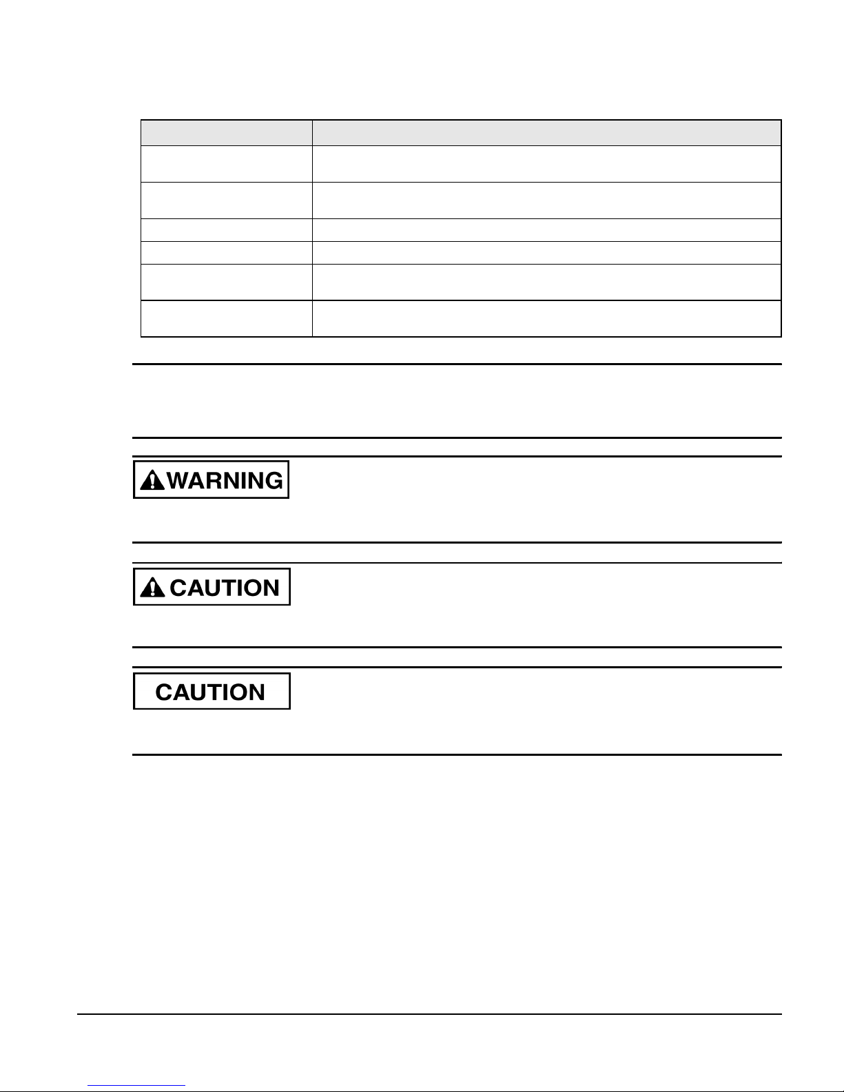
Note
For the purpose of this manual and product, “Note” indicates essential information about
the product or the respective part of the manual.
“Warning” indicates a potentially hazardous situation that, if not avoided, could result in
death or serious injury.
“Caution” indicates a potentially hazardous situation that, if not avoided, may result in
minor or moderate injury.
“Caution” used without the safety alert symbol indicates a potentially hazardous situation
that, if not avoided, may result in property damage.
Safety Instructions
General Warning
Failure to follow safe installation guidelines can cause death or serious injury. The voltages
used in the product can cause severe electric shock and/or burns and could be lethal. Extreme
care is necessary at all times when working with or adjacent to the product. The installation
must comply with all relevant safety legislation in the country of use.
v
Page 8

Qualified Person
For the purpose of this manual and product, a “qualified person” is one who is familiar with
the installation, construction and operation of the equipment and the hazards involved. In
addition, this individual has the following qualifications:
• Is trained and authorized to energize, de-energize, clear and ground and tag circuits and
equipment in accordance with established safety practices.
• Is trained in the proper care and use of protective equipment in accordance with
established safety practices.
• Is trained in rendering first aid.
vi
Page 9

AXIMA® 2000/4000 Multi-axis Controller
CE Declaration of Conformity
The AXIMA 2000/4000 Multi-axis Controllers are marked with the “Conformite Europeenne
Mark” (CE mark) after passing a rigorous set of design and testing criteria. This label
indicates that this product meets safety and noise immunity and emmisions (EMC) standards
when installed according to the installation guidelines and used within the product
specifications.
Installation Manual
vii
Page 10
AXIMA® 2000/4000 Multi-axis Controller Installation Manual
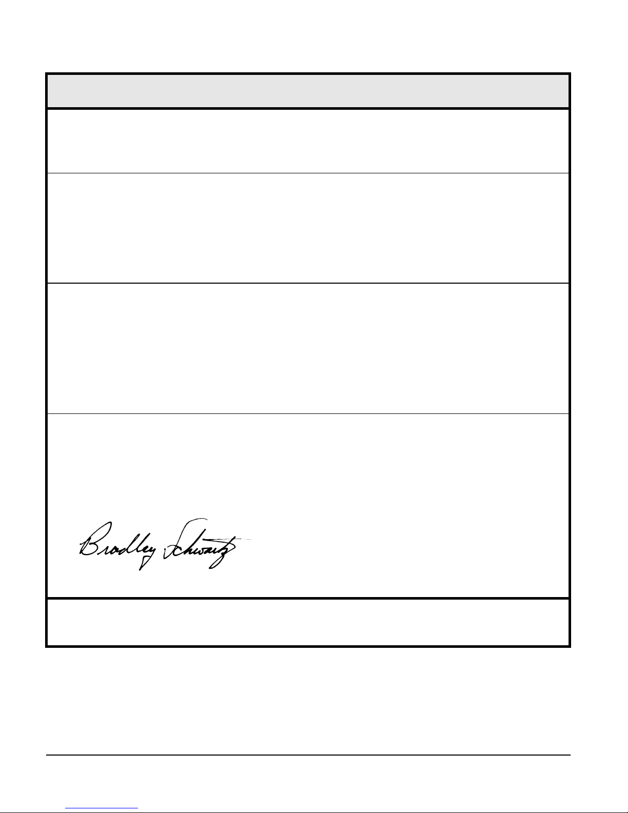
Declaration of Conformity
Manufacturer’s Name:
Manufacturer’s Address:
Control Techniques
12005 Technology Drive
Eden Prairie, MN 55344
USA
Declares that the following products:
Products Description:
Model Number:
System Options:
AXIMA 2000/4000 Multi-axis Controller
AXIMA 2000 and AXIMA 4000
This declaration covers the above products with the stepper axis, source mode expanded I/O,
analog inputs, Modbus and Data Highway Plus.
Conforms to the following product specification:
Electomagnetic Compatibility (EMC):
EN 55011/1991 Class A Group 1, CISPR 11/1990 Class A Group 1
EN 50082-2/1995: IEC 1000-4-2/1995; EN 61000-4-2, 4kV CD
IEC 1000-4-3/1995; EN 61000-4-3, ENV 50140/1993, 80% AM, 10V/m @ 3 m
IEC 1000-4-4/1995; EN 61000-4-4, 2 kV ALL LINES
IEC 1000-4-8/1993; EN 61000-4-8, 30 A/m
ENV 50141/1993, 80% AM, 10V, .15-80 MHz
ENV 50204/1995, Pulse, 900 MHz, 50% DTY, 200 Hz
Supplementary information:
The products herewith comply with the requirements of the Low Voltage Directive (LVD) 73/23/EEC and EMC Directive 89/336/EEC
This electronic drive product is intended to be used with an appropriate motor, electrical protection components and other equipment to form a complete end
product or system. It must only be installed by a professional assembler who is familiar with requirements for safety and electromagnetic compatibility
(“EMC”). The assembler is responsible for ensuring that the end product or system complies with all the relevant laws in the country where it is to be used.
Refer to the product manual for installation guidelines.
February 24, 1999
Bradley Schwartz/ VP Engineering Date
European Contact:
Sobetra Automation
Langeveldpark Lot 10
P. Dasterleusstraat 2
1600 St. Pieters Leeuw, Belgium
viii
Page 11

AXIMA® 2000/4000 Multi-axis Controller
Installation Manual
Table of Contents
Introduction 1
Connections and Features . . . . . . . . . . . . . . . . . . . . . . . . . . . . . . . . . . . . . . . . . . . . . . . . . . . . . . . 3
Installation 5
Safety Considerations . . . . . . . . . . . . . . . . . . . . . . . . . . . . . . . . . . . . . . . . . . . . . . . . . . . . . . . . . . 5
Environmental Concerns . . . . . . . . . . . . . . . . . . . . . . . . . . . . . . . . . . . . . . . . . . . . . . . . . . . . . . . . 8
Basic Installation Notes . . . . . . . . . . . . . . . . . . . . . . . . . . . . . . . . . . . . . . . . . . . . . . . . . . . . . . . . . 8
Mounting Requirements . . . . . . . . . . . . . . . . . . . . . . . . . . . . . . . . . . . . . . . . . . . . . . . . . . . . . . . . 9
System Grounding Requirements . . . . . . . . . . . . . . . . . . . . . . . . . . . . . . . . . . . . . . . . . . . . . . . . 10
Power Requirements . . . . . . . . . . . . . . . . . . . . . . . . . . . . . . . . . . . . . . . . . . . . . . . . . . . . . . . . . . 14
Connections and Cabling 17
Serial Communications . . . . . . . . . . . . . . . . . . . . . . . . . . . . . . . . . . . . . . . . . . . . . . . . . . . . . . . . 17
COM Port 1 . . . . . . . . . . . . . . . . . . . . . . . . . . . . . . . . . . . . . . . . . . . . . . . . . . . . . . . . . . . . . . . . . 17
COM Port 2 . . . . . . . . . . . . . . . . . . . . . . . . . . . . . . . . . . . . . . . . . . . . . . . . . . . . . . . . . . . . . . . . . 19
Controller ID Number/Address . . . . . . . . . . . . . . . . . . . . . . . . . . . . . . . . . . . . . . . . . . . . . . . . . . 28
Axis Connections. . . . . . . . . . . . . . . . . . . . . . . . . . . . . . . . . . . . . . . . . . . . . . . . . . . . . . . . . . . . . 30
Encoder 1 or 3 Output Connection . . . . . . . . . . . . . . . . . . . . . . . . . . . . . . . . . . . . . . . . . . . . . . . 41
Input/Output Connections . . . . . . . . . . . . . . . . . . . . . . . . . . . . . . . . . . . . . . . . . . . . . . . . . . . . . . 43
Diagnostics Status Display . . . . . . . . . . . . . . . . . . . . . . . . . . . . . . . . . . . . . . . . . . . . . . . . . . . . . 49
Analog Input Option 51
Axis Inputs Connector Wiring. . . . . . . . . . . . . . . . . . . . . . . . . . . . . . . . . . . . . . . . . . . . . . . . . . . 53
Expanded I/O Option 55
Sinking Versus Sourcing . . . . . . . . . . . . . . . . . . . . . . . . . . . . . . . . . . . . . . . . . . . . . . . . . . . . . . . 55
Direct Wiring Option. . . . . . . . . . . . . . . . . . . . . . . . . . . . . . . . . . . . . . . . . . . . . . . . . . . . . . . . . . 57
Connectivity Options 69
Modbus Connection. . . . . . . . . . . . . . . . . . . . . . . . . . . . . . . . . . . . . . . . . . . . . . . . . . . . . . . . . . . 72
Data Highway Plus Connection. . . . . . . . . . . . . . . . . . . . . . . . . . . . . . . . . . . . . . . . . . . . . . . . . . 73
ix
Page 12

AXIMA® 2000/4000 Multi-axis Controller Installation Manual
Stepper Option 75
Specifications 77
AXIMA® 2000/4000 Controller Options . . . . . . . . . . . . . . . . . . . . . . . . . . . . . . . . . . . . . . . . . . 77
Specifications . . . . . . . . . . . . . . . . . . . . . . . . . . . . . . . . . . . . . . . . . . . . . . . . . . . . . . . . . . . . . . . 79
Heat Dissipation . . . . . . . . . . . . . . . . . . . . . . . . . . . . . . . . . . . . . . . . . . . . . . . . . . . . . . . . . . . . . 80
Dimensions and Clearances . . . . . . . . . . . . . . . . . . . . . . . . . . . . . . . . . . . . . . . . . . . . . . . . . . . . 80
Cable Diagrams . . . . . . . . . . . . . . . . . . . . . . . . . . . . . . . . . . . . . . . . . . . . . . . . . . . . . . . . . . . . . . 81
Glossary 87
Index 91
x
Page 13
AXIMA® 2000/4000 Multi-Axis Controller
Installation Manual
Introduction
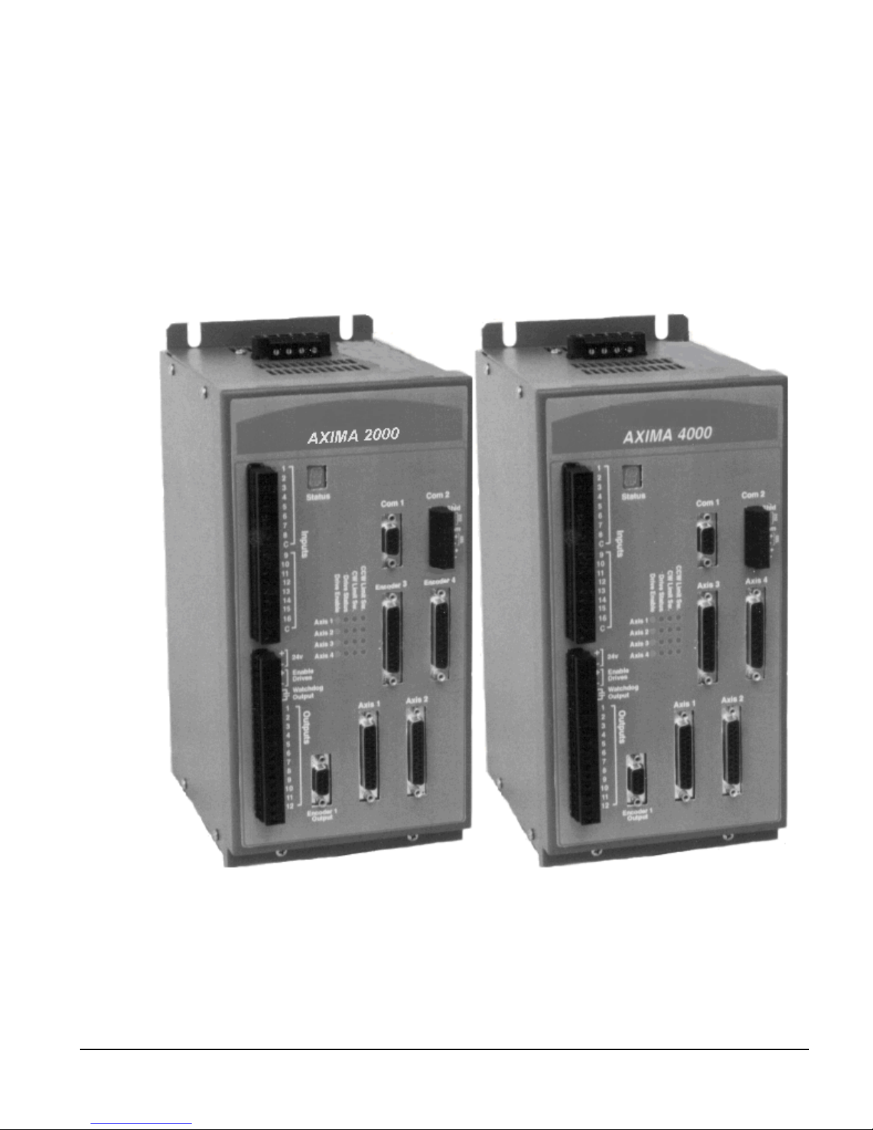
The AXIMA® 2000 or AXIMA 4000 multi-axis controller from Control Techniques provides
a fully integrated solution for servo control motors. It also provides a simple operator
interface, machine I/O and host communications in one unit. Housed in an industrial hardened
chassis, AXIMA 2000/4000 controller combines digital servo control and 41 optically
isolated I/O lines to create a powerful tool for solving motion control applications that require
coordinated control of up to four axes.
Figure 1: AXIMA 2000 and 4000 Multi-Axis Controllers
The AXIMA 2000/4000 controller uses a 32-bit floating point Digital Signal Processor
(DSP). The DSP gives the AXIMA 2000/4000 controller the processing power, flexibility and
functionality to handle the wide range of multi-axis applications found in plant automation
and industrial machinery.
1
Page 14

AXIMA® 2000/4000 Multi-Axis Controller Installation Manual
With AXIMA 2000/4000 controller, as many as four Motion, eight PLC and eleven Auxiliary
Programs can be operating simultaneously and control up to four separate coordinate systems,
with one axis of motion each, one coordinate system with up to four axes of motion, or any
combination of up to four coordinate systems and up to four axes of motion.
The onboard executive program allows axis assignments to be made to create one or multiple
coordinate systems. Each coordinate system operates from an independent program. This
allows the programmer to concentrate on one coordinate system at time.
2
Page 15
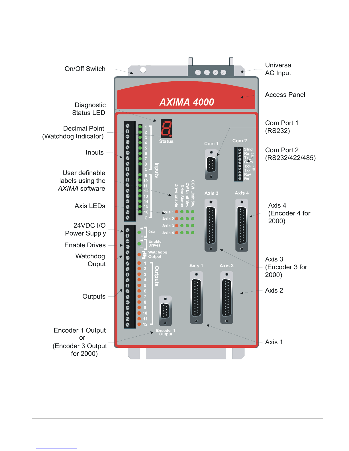
Connections and Features
Introduction
Figure 2: AXIMA 2000/4000 Controller Front Panel Connections
3
Page 16

AXIMA® 2000/4000 Multi-Axis Controller Installation Manual
4
Page 17

AXIMA® 2000/4000 Multi-Axis Controller
Safety Considerations
The AXIMA® multi-axis controller is intended for professional incorporation into a complete
system. If installed incorrectly, it may present a safety hazard. The product uses high voltages
and is used to control mechanical equipment which can cause injury. Close attention is
required to the electrical installation and the system design to avoid hazards either in normal
operation or in the event of equipment malfunction. System design, installation,
commissioning and maintenance must be carried out by personnel who have the necessary
training and experience. They must read this safety information and the instruction manual
carefully.
It is your responsibility to comply with the safety requirements of your system. This includes
installing the system with an appropriate master interlock switch for emergency shutdown
that will remove AC power from the system any time the equipment is not running or the
emergency stop is activated. This reduces the possibility of electrocution or unwanted motion.
Installation Manual
Installation
Enclosure
The controller is intended to be mounted in an enclosure which prevents access except by
trained and authorized personnel, and which prevents the ingress of contamination.
The controller was designed for use in an environment classified as pollution degree 2 in
accordance with IEC 664-1, meaning that only dry, non-conducting contamination is
acceptable.
Selecting an Enclosure
The AXIMA 2000/4000 multi-axis controller is designed for most industrial environments.
However, no sophisticated electronic system can tolerate atmospheric contaminants such as
moisture, oils, conductive dust, chemical contaminants and metallic particles. If the AXIMA
2000/4000 controller is going to be subject to this type of environment, it must be mounted
in a metal enclosure with a minimum rating of NEMA 12.
The temperature inside the enclosure should not exceed 40° C (104° F).
If the ambient temperature exceeds 40° C (104° F) active cooling must be installed.
Setting Up, Commissioning and Maintenance
It is essential that changes to the controller settings are given careful consideration.
Depending on the application, a change could have an impact on safety. Appropriate
precautions must be taken against inadvertent changes or tampering.
5
Page 18

AXIMA® 2000/4000 Multi-Axis Controller Installation Manual
Restoring default parameters set in certain applications may cause unpredictable or hazardous
operation.
Safety of Machinery
Within the European Union all machinery in which this product is used must comply with
Directive 89/392/EEC, Safety of Machinery.
The AXIMA 2000/4000 hardware and PowerTools software are designed and tested to a high
standard, and failures are very unlikely. However the level of integrity offered by an AXIMA
2000/4000 control function – for example stop/start, forward/reverse and maximum speed –
is not sufficient for use in safety-critical applications without additional independent channels
of protection. All applications where malfunction could cause injury or loss of life must be
subject to a risk assessment, and further protection provided where needed.
Electromagnetic Compatibility (EMC)
The AXIMA 2000/4000 controllers are designed to the high standards of EMC. Under
extreme conditions an AXIMA 2000/4000 controller might cause or suffer from disturbances
due to electromagnetic interaction with other equipment. It is the responsibility of the installer
to ensure that the equipment or system into which the drive is incorporated complies with the
relevant EMC legislation in the country of use.
The following instructions provide you with installation guidance designed to help you meet
the requirements of the EMC Directive 89/336/EEC.
Although Control Techniques cannot guarantee your system will meet tested emission or
immunity requirements, adhering to the following guidelines will greatly improve the
electromagnetic compatibility of your system.
• Choose an enclosure made of a conductive material, such as carbon steel, aluminum or
stainless steel.
• Devices mounted to the enclosure mounting plate, which depend on their mounting
surfaces for grounding, must have the paint removed from their mounting surfaces and the
mating area on the mounting plate to ensure a good ground. The AXIMA 2000/4000
controller does not require removal of paint.
• If grounding is required for cable grommets, connectors and/or conduit fittings at
locations where cables are mounted through the enclosure wall, paint must be removed
from the enclosure surface at the contact points.
• AC line filter input and output wires and cables should be shielded, and all shields must
be grounded to the enclosure.
Although final responsibility for EMC compliance rests with the machine builder, we are
including the following installation suggestions. They describe the components that were
used and how they were installed during the EMC compliance testing.
6
Page 19

Installation
Achieving Low Impedance Connections
Immunity can be improved and emissions reduced by maintaining the components of the
installation at the same ground potential. Establishing zero potential difference between
components requires a low impedance connection between the components.
This can be achieved by bringing the conductive surfaces of the components into direct
contact. Over the short term this can be very effective. Over an extended period of time,
degradation of the connection may occur due to corrosion. Corrosion can occur when a
material reacts with the atmosphere or when two dissimilar materials react with each other.
Therefore component materials should be conductive, compatible and exhibit good
atmospheric corrosion resistance.
Bringing components into direct contact cannot always be achieved. In these situations a
conductor must be relied upon to provide a low impedance path between components. The
impedance of the conductor is dependent on conductivity and frequency. Conductors that
provide a low impedance path at low frequencies may not provide a low impedance path at
higher frequencies.
A good rule to follow when specifying conductors for high frequency applications is to use a
metal strap with a length to width ratio that is less than 3:1.
A low impedance connection should exist between the following components, but not limited
to:
• Enclosure and mounting plate
• Servo amplifier chassis and mounting plate
• EMI/RFI AC line filter chassis and mounting plate
• Other interface equipment chassis and mounting plate
• Other interface equipment chassis and electrical connectors
• Enclosure and conduit fittings or electrical connectors
• Enclosure mounting plate and earth ground
• Motor chassis and conduit fittings or electrical connectors
• Encoder chassis and electrical connector
• Cable shields when and where they should be grounded
Note
It is critical that you keep the filter inputs routed away from any electrical noise sources
to prevent noise from being induced into them and carried out of the enclosure.
7
Page 20

AXIMA® 2000/4000 Multi-Axis Controller Installation Manual
Environmental Concerns
If your AXIMA 2000/4000 controller will be subjected to atmospheric contaminants such as
moisture, oils, conductive dust, chemical contaminants and metallic particles, you must
mount it vertically in a metal NEMA type 12 enclosure.
If the ambient temperature inside the enclosure will exceed 40° C (104° F), you must consider
forced air cooling. The amount of cooling depends on the size of the enclosure, the thermal
transfer of the enclosure to the ambient air and the amount of power being dissipated inside
the enclosure.
Basic Installation Notes
You are required to follow all safety precautions during start-up, such as providing proper
equipment grounding, correctly fused power and an effective Emergency Stop circuit which
can immediately remove power in the case of a malfunction.
• To avoid problems associated with Electromagnetic Interference (EMI), you should route
high power lines (AC input power and motor power) away from low power lines (encoder
feedback, serial communications, etc.).
• You should consider future troubleshooting and repair when installing all wiring. All
wiring should be either color coded and/or tagged with industrial wire tabs.
• As a general rule, the minimum cable bend radius is ten times the cable outer diameter.
• All wiring and cables, stationary and moving, must be protected from abrasion.
• Ground wires should not be shared with other equipment. Also ensure that metal to metal
contact is made between the enclosure ground lug and the metal enclosure.
• All inductive coils must be suppressed with appropriate devices, such as diodes or
resistor/capacitor (RC) networks.
General Warning
Failure to follow safe installation guidelines can cause death or serious injury. The
voltages used in the unit can cause severe electric shock and/or burns, and could be lethal.
Extreme care is necessary at all times when working with or adjacent to it. The installation
must comply with all relevant safety legislation in the country of use.
AC supply Isolation device
The AC supply must be removed from the controller using an approved isolation device
or disconnect before any servicing work is performed, other than adjustments to the
settings or parameters specified in the manual.
Grounding (Earthing, equipotential bonding)
The controller must be grounded by a conductor sufficient to carry the prospective fault
8
Page 21

current in the event of a fault. The ground connections shown in the manual must be
adhered to.
Fuses
Fuses or over-current protection must be provided at the input in accordance with the
instructions in the manual. Failure to observe the instructions closely may cause a fire
hazard.
Isolation of control circuits
The control circuits are isolated from the power circuits in the controller by basic
insulation only. The installer must ensure that the external control circuits are isolated
from human contact by at least one layer of insulation rated for use at the applied AC
supply voltage.
Mounting Requirements
The AXIMA 2000/4000 controller should be back mounted vertically in a metal NEMA
enclosure. A minimum spacing of four inches must be maintained above and below the
controller for ventilation. The following diagram shows the dimensions of the AXIMA 2000/
4000 controller.
Installation
9
Page 22

AXIMA® 2000/4000 Multi-Axis Controller Installation Manual
11.70
(297.18)
0.9
(22.86)
3.0
(76.20)
1.25
(31.75)
5.5
(139.70)
3.68
(98.30)
3.0
(76.20)
7.1
(183.00)
0.25
(6.35)
11.19
(284.23)
0.20 (5.08) typ. 4 places
Dimensions in ( ) are in millimeters.
Figure 3: Mounting Dimensions
System Grounding Requirements
AXIMA 2000/4000 Controller Grounding
The PE terminal of the AXIMA 2000/4000 controller is internally bonded to the chassis. The
enclosure PE and the AXIMA 2000/4000 controller PE should have a common signal point
that ultimately is a continuous path to earth ground. These ground wires of the AXIMA 2000/
4000 controller should not be shared with other equipment in the enclosure.
The TE terminal is connected to the internal digital ground of the AXIMA. The TE
connection should be tied to the PE connection in the enclosure. Do not jumper the connection
to the PE terminal on the AC input connector.
10
Page 23
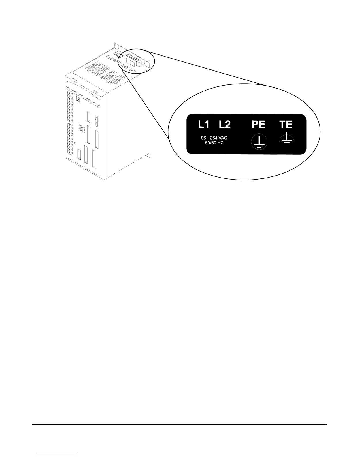
Installation
Figure 4: AXIMA 2000/4000 Controller Grounding Point
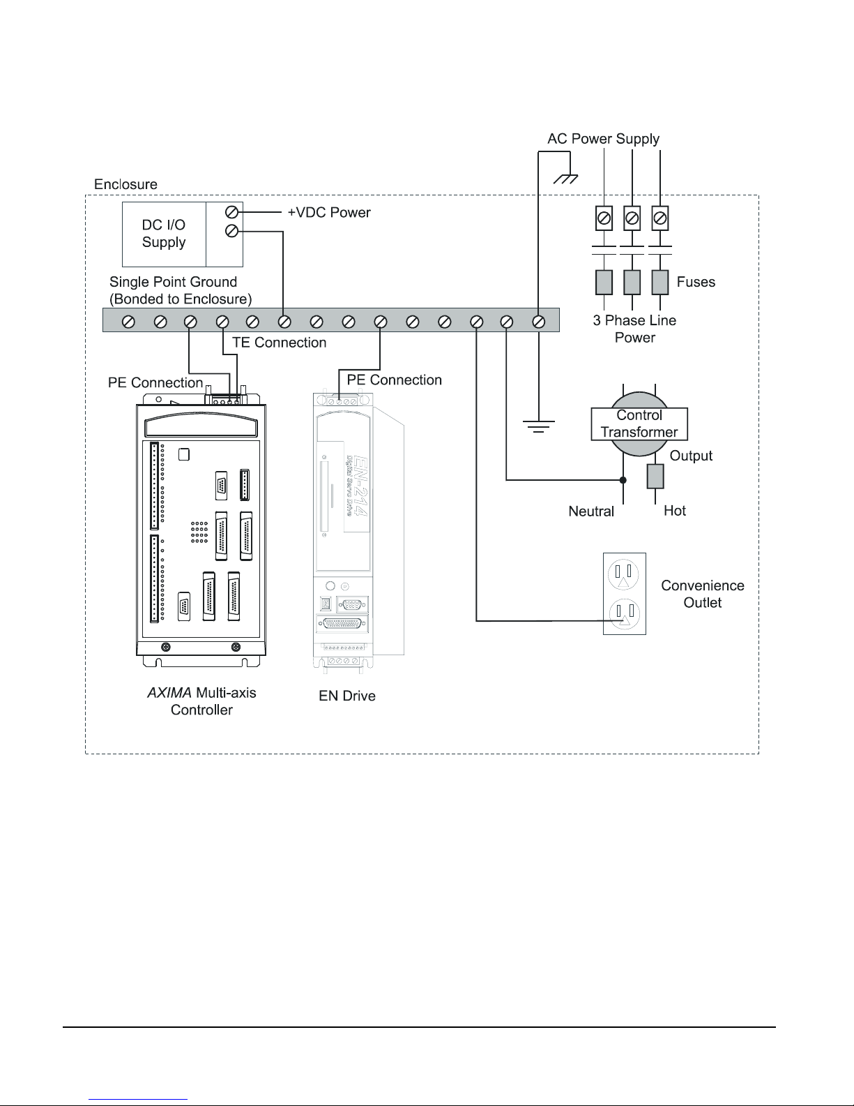
The AXIMA 2000/4000 controller PE terminal must be connected to the equipment
grounding conductor of the AXIMA’s AC supply circuit and bonded to the enclosure. This
should be accomplished with a short wire from the PE terminal to a grounding block in the
enclosure. All other equipment in the enclosure must use its own connection to this grounding
block.
11
Page 24
AXIMA® 2000/4000 Multi-Axis Controller Installation Manual
AXIMA/E Series Drives Grounding Example
Figure 5: E Series Drive and AXIMA System Grounding Diagram
12
Page 25
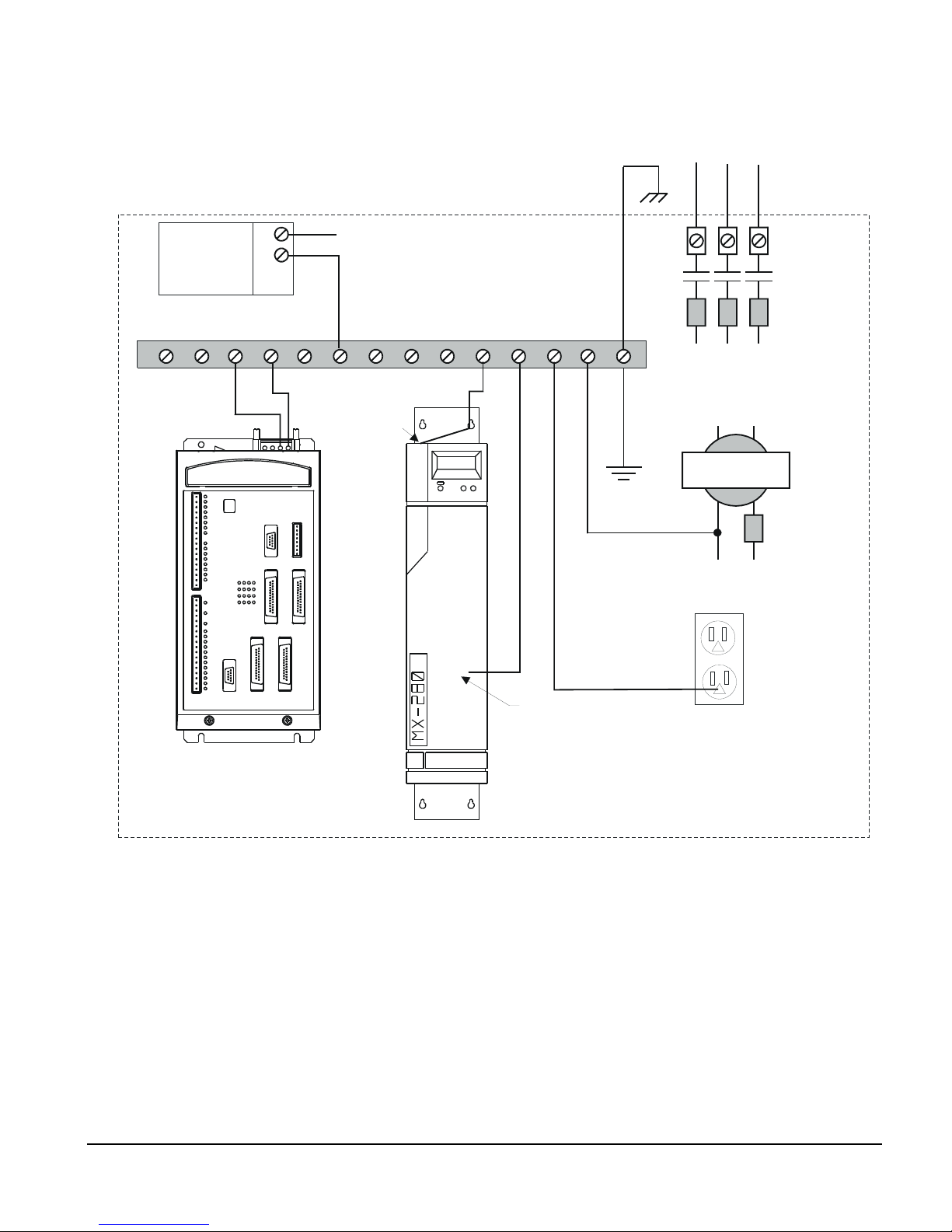
AXIMA/MX Drives Grounding Example
Enclosure
Installation
AC Power Supply
DC I/O
Supply
Single Point Ground
(Bonded to Enclosure)
TE Connection
PE Connection
+ VDC Power
Jumper from
AMP GND to
"Y" Terminal
3 Phase Line
Power
Transformer
Neutral
Fuses
Control
Output
Hot
Convenience
Outlet
Pin 11
AXIMA Multi-axis
Controller
MX Digital
Servo Drive
Figure 6: MX Drive and AXIMA System Grounding Diagram
13
Page 26
AXIMA® 2000/4000 Multi-Axis Controller Installation Manual
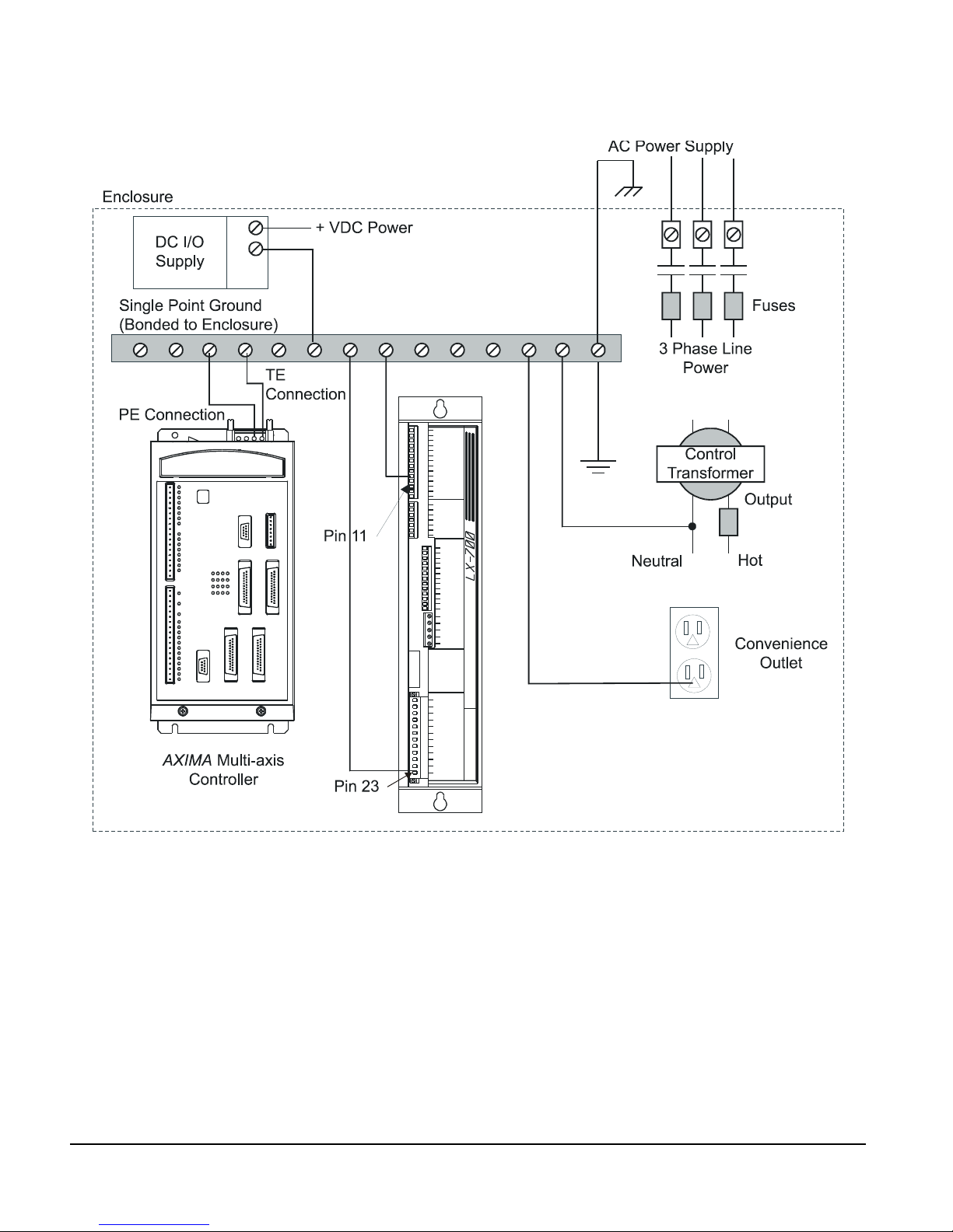
AXIMA/LX Drives Grounding Example
Figure 7: LX Drive and AXIMA System Grounding Diagram
Power Requirements
Rated AC power input is 120 VAC at 1 A or 240 VAC at 0.5 A, single phase, 50 or 60 Hz.
AC power must be between 96 and 204 VAC.
The AC power connects to a removable connector on the top of the AXIMA 2000/4000
chassis. The AC power input must be between 96 and 264 VAC, single phase, and 50 to 60
Hertz. At 115 VAC, 1.0 Amps RMS is required, or at 230 VAC, 0.5 Amps RMS is required.
However, at power-up the unit has an inrush current that is typically 20 Amps at 115 VAC
14
Page 27

Installation
and 40 Amps at 230 VAC for 2 milliseconds. This inrush current must be considered when
choosing AC power fusing.
Note
The AC Power removable connector terminals are to be torqued 6 to 7 inch pounds at
installation of wiring.
Figure 8: AC Power Connector
AC Supply
Volt age
115 VAC 1 Amp 20 Amps FLM-2 or equivalent
230 VAC 0.5 Amp 40 Amps 2 Amp Slo-Blo
Current
Inrush Current
(2 ms)
External Fusing Requirement
The AC power supply must be fused with a 2 amp fuse in each ungrounded line. A grounded
line (neutral) must not be fused. Littelfuse
can be used.
®
’s FLM-2 SLO-BLO type fuse, or an equivalent,
Fusing Frequency (Hz) AC Supply Limit
50/60 96 to 264 VAC
15
Page 28

AXIMA® 2000/4000 Multi-Axis Controller Installation Manual
Grounded Supply Requirement
A significant AC power problem occurs when the secondary of the AC distribution
transformer is not electrically referenced to earth ground (i.e., left floating). In this case, the
voltages that develop between the AC power lines and earth ground can continuously exceed
the voltage limit of 264 VAC. When this happens the protection circuit in the AXIMA 2000/
4000 controller will try to suppress this excess voltage. If the condition is prolonged, the
AXIMA 2000/4000 controller protection circuits will fail.
The voltage limit of 264 VAC applies from L1 to PE and L2 to PE as well as from L1 to L2.
Use a ground referenced AC supply.
16
Page 29
AXIMA® 2000/4000 Multi-Axis Controller
Serial Communications
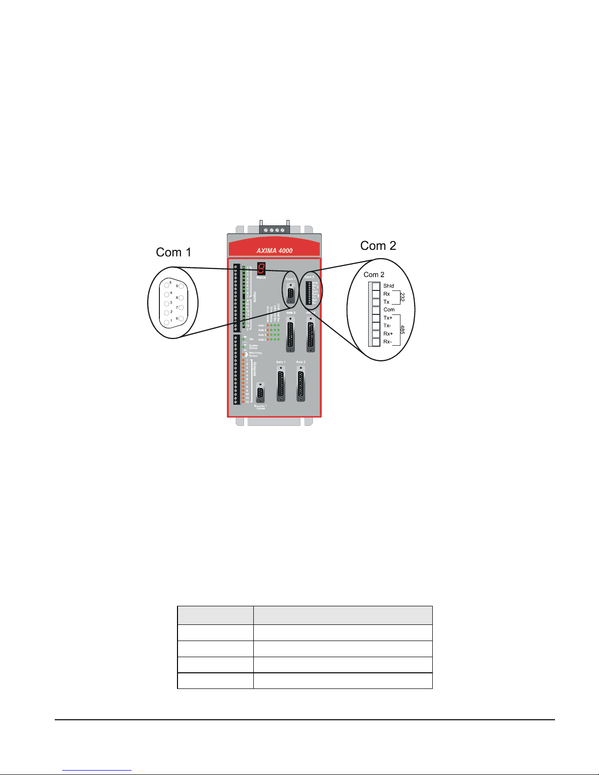
The AXIMA® 2000/4000 controller has two optically isolated serial ports (COM 1 and COM
2). COM 1 is a RS232 port. COM 2 can be configured for RS232, RS422 or RS485 using DIP
switches located behind the removable access panel on the top front of the AXIMA 2000/
4000 controller.
Installation Manual
Connections and Cabling
Figure 9: AXIMA 2000/4000 Controller Communication Ports, Com 1 and Com 2
COM Port 1
The AXIMA 2000/4000 controller COM 1 connection is a RS232 serial communication port.
The COM 1 port is activated and will automatically detect the baud rate by receiving one
carriage return after power up. Both serial ports, COM 1 and COM 2, can be open
simultaneously and attached to different programs. For example, one port could be used as a
programming and diagnostics port while the second port is communicating with an operator
interface panel such as the Control Techniques T-60 panel.
Pin Number Description
1 Shield
2Rx
3Tx
4 Not connected
17
Page 30
AXIMA® 2000/4000 Multi-Axis Controller Installation Manual
Pin Number Description
5 Common
6 Not connected
7 Not connected
8 Not connected
9 Not connected
Note
The COM 1 port is supplied through a DC-to-DC convertor which is isolated from the
main board’s 5 VDC supply. All communications signals are isolated using optoisolators.
Serial Port and Cable Specifications
It is recommended that all communication lines be twisted pair shielded cable. Cables should
be routed away from motor power and other high voltage or noisy wiring.
Serial Communication Setup
Max baud rate 38.4 K
Stop bit 1
Data bits 8
Parity none
The RS232 serial communication cables should be no longer than 50 feet to comply with
RS232 specifications. However, longer cables may be used at slower baud rates (less than
9600). The wiring diagrams on the next page show the TIX and TIA serial cables which are
available from Control Techniques in 10, 25 and 50 foot lengths. Non-standard lengths can
be special ordered.
18
Page 31

13
25
12
24
11
23
10
22
9
21
8
20
7
19
6
18
5
17
4
16
3
15
2
14
1
25 PIN
"D" CONNECTOR
FEMALE
COMPUTER
Tx
2
Rx
3
GND
7
PIN
NUMBER
TIX-XXX CABLE
TIA-XXX CABLE
COM 1
Rx
Tx
GND
SHLD
Connections and Cabling
2
3
5
1
PIN
NUMBER
5
9
4
8
3
7
2
6
1
9 PIN
"D" CONNECTOR
MALE
5
9
4
8
3
7
2
6
1
9 PIN
"D" CONNECTOR
FEMALE
Figure 10: RS232C Serial Communication Cables Wiring Diagram
COM Port 2
To communicate with more than one AXIMA 2000/4000 controller, and using the AXIMA
Software or other host controller, you must use COM 2 configured as an RS485. The COM 2
serial communication port is shipped as a RS232 as default.
DIP Switch Settings
COM 2 can be configured for RS232, RS422 or RS485 using switches located behind the
removable access panel on the top front of the AXIMA 2000/4000 controller.
COMPUTER
Tx
3
Rx
2
GND
5
PIN
NUMBER
COM 1
Rx
Tx
GND
SHLD
2
3
5
1
PIN
NUMBER
5
9
4
8
3
7
2
6
1
9 PIN
"D" CONNECTOR
MALE
19
Page 32

AXIMA® 2000/4000 Multi-Axis Controller Installation Manual
Figure 11: AXIMA 2000/4000 Controller DIP Switches Location
RS232 DOWN
RS422 UP DOWN DOWN DOWN
RS485 (2 wire/SD) UP UP UP UP
RS485 (4 wire/SD) UP DOWN UP UP
RS485 (4 wire/RTS) UP DOWN DOWN UP
20
DIP Switch Settings
1 2 3 4
Page 33

Mode Selection
RS232C Mode (Default Mode)
The AXIMA 2000/4000 controller is shipped with COM 2 in RS232 mode.
RS232C
DEVICE
Figure 12: COM 2, RS232 Configuration
Tx
Rx
GND
Com 2
1
2
3
4
5
6
7
8
Connections and Cabling
Shld
Rx
Tx
Com
Tx+
Tx-
Rx+
Rx-
232 485
Note
The COM 2 port is supplied through a DC-to-DC convertor which is isolated from the
main board’s 5 VDC supply. All communications signals are isolated using optoisolators.
RS422 Mode
With COM 2 in RS422 mode, the transmitter is not put into a tri-state mode. The Tx
(Transmit) lines of multiple AXIMA 2000/4000 controllers CAN NOT be wired together.
The receive line of the last AXIMA should be terminated with a 100 ohm ½ watt resistor. See
Figure 13.
RS485 Mode
RS422 and RS485 modes are similar because they both use differential drivers and receivers.
RS485 mode adds the ability to enable and disable the receivers and transmitters as required
for multidrop installations. See Figure 14 and 15.
The enable and disable operations of the AXIMA 2000/4000 controller serial port can be
selected to operate in two different transmission methods. These methods are selectable with
a DIP switch behind the access panel on the top front of the controller. It is labeled, SD (Send
Data) or RTS (Ready to Send). See Figure 11.
SD (Send Data) Method:
This is the simplest mode. Whenever the AXIMA 2000/4000 controller serial port senses that
data is present the transmitter is enabled. The transmitter stays enabled long enough to assure
the last bit has been sent then it disables or tri-states the transmission. It does this for baud
21
Page 34

AXIMA® 2000/4000 Multi-Axis Controller Installation Manual
rates down to 9600 baud. The transmitter is in tri-state mode or disabled when data is not
being sent so it can receive data.
RTS (Ready to Send) Method:
This method enables the transmitter under two conditions.
1. When a particular AXIMA 2000/4000 controller has been chosen by the host to be
online, the command, CTRL A - “Axis ID #” - Enter, is issued. The transmitter stays
enabled until a “CTRL B” command is received.
2. When the AXIMA Software Application executes an Open Com Instruction, the
transmitter is enabled. The transmitter goes back to tri-state mode when a Close Com
Instruction is issued. See the AXIMA Software User’s Guide (P/N 400263-00) for more
information.
The Echo On/Off DIP switch controls the enable/disable function of the AXIMA receiver.
With the switch “On”, the receiver is always enabled. This switch should be “On” for RS422
and RS485 four wire operation. With the switch “Off”, the receiver is disabled whenever the
transmitter is enabled. This is needed for two wire mode. This is to prevent the AXIMA 2000/
4000 controller from receiving the same characters it just transmitted.
The figure below shows a wiring diagram for serial communications of a RS422
configuration.
22
Page 35

Connections and Cabling
GND
NC
NC
NC
100
Ω
½ WATT
TYPICALLY
UP TO 10
SLAVES
SEE NOTE
BELOW
NC
15
E
Figure 13: RS422 Two Wire Muli-Drop Wiring Diagram
Note
A standard RS-422 host transmitter can drive up to 10 slaves. However, the AXIMA
transmitter can drive up to 15 slaves in RS-422 mode.
The figure below shows a wiring diagram for serial communications in an RS485 four wire
multi-drop configuration.
23
Page 36

AXIMA® 2000/4000 Multi-Axis Controller Installation Manual
GND
UP TO 15
SLAVES
24
15
E
Figure 14: RS485 Four Wire Multi-Drop Wiring Diagram
The figure below shows a wiring diagram for serial communications of a RS485 two wire
termination connection.
Page 37

GND
Connections and Cabling
UP TO 15
SLAVES
15
E
Figure 15: RS485 Two Wire Termination Connection Wiring Diagram
RS485 termination
Two 120 ohm, ½ watt resistors must be installed on an RS-485 network, one at the node (RS485 port) physically at the beginning of the cable and one on the node at the end.
25
Page 38

AXIMA® 2000/4000 Multi-Axis Controller Installation Manual
Com 2
Shld
1
Rx
2
Tx
3
Isolated Com *
4
Tx+
5
Tx-
6
Rx+
7
Rx-
8
* Isolated from the rest of the
AXIMA Controller through a
DC-to-DC convertor.
RS485
or
RS422
Device
GND
Rx +
Rx -
Tx +
Tx -
Figure 16: COM 2, RS485 Configuration
Serial Port Grounding
The AXIMA 2000/4000 controller provides an isolated logic supply for its communication
circuitry. COM is the circuit common for both COM port circuits. COM 1 and COM 2
devices, such as PC serial ports, typically have signal ground connected to earth ground
internally in the PC.
If your COM devices do not have signal grounds that are common with respect to each
other (such as both connected to earth ground) then you must connect them together.
Failure to connect device grounds together could cause damage to the device or the
AXIMA 2000/4000 controller.
26
Page 39

INTERNALLY
CONNECTED
COM 1
5
9
4
8
3
7
2
6
1
9 PIN
"D" CONECTOR
COM 2
Shld
1
Rx
2
Tx
3
Com
4
Tx+
5
Tx-
6
Rx+
7
Rx-
8
232 485
COM 1 DEVICE
(RS232C)
SIGNAL
COMMON
COM 2 DEVICE
(RS422 OR RS485)
SIGNAL
COMMON
Connections and Cabling
GROUND
GROUND
Figure 17: Serial Communications Grounding Diagram
Serial Port and Cable Specifications
It is recommended that all communication lines be twisted pair shielded cable. Low
capacitance shielded twisted pair cable will deliver optimum performance especially with
long cable lengths and high baud rates. Cables should be routed away from motor power and
other high voltage or noisy wiring.
Serial Communication Setup
Max baud rate 38.4 K
Stop bit 1
Data bits 8
Parity none
Note
As baud rates increase or cable lengths get longer your susceptibility to noise increases.
Therefore, if you are experiencing communication problems, it is recommended that you
install a ½ watt terminating resistor, 100 ohm for RS422 and 120 ohm for RS485.
27
Page 40

AXIMA® 2000/4000 Multi-Axis Controller Installation Manual
Controller ID Number/Address
The following table shows how the Address DIP switch positions relate to the AXIMA 2000/
4000 controller axis ID number. The DIP switches are located behind the top front access
panel of the AXIMA 2000/4000 controller.
Figure 18: AXIMA 2000/4000 Controller Address DIP Switch Location
AXIMA ID Address DIP Switch Settings
1 2 3 4
0 OFF OFF OFF OFF
1 OFF OFF OFF ON
2OFFOFFONOFF
28
Page 41

Connections and Cabling
AXIMA ID Address DIP Switch Settings
3OFFOFFONON
4 OFF ON OFF OFF
5 OFF ON OFF ON
6 OFF ON ON OFF
7 OFF ON ON ON
8 ON OFF OFF OFF
9ONOFFOFFON
A ON OFF ON OFF
B ON OFF ON ON
CONONOFFOFF
DONONOFFON
EONONONOFF
Reserved ON ON ON ON
Note
The following procedure is needed if a corrupted program is run on power-up or in making
communications.
The reserved address setting is used for bypassing the flash memory and ignoring the run on
power-up command for programs in the Application. This is needed if the flash memory
becomes corrupted. Corrupted flash can lock-up communications and load the corrupted
program into RAM on power-up. This requires revision A7 or later firmware. The
instructions for using this function are as follows:
1. Turn the AXIMA 2000/4000 controller power “Off”.
2. Set the DIP switches to the reserved positions. (All switches in the “On” position).
3. Turn the AXIMA 2000/4000 controller power “On”.
4. Set the DIP switches back to the address being used.
5. Download the AX-WIN Application.
Multi-Drop Installations
If your application uses more than one AXIMA 2000/4000 controller (up to 15 can be linked
serially), each must have a different ID number. This allows each AXIMA 2000/4000
controller to be addressed individually over the same multi-drop serial cable in the RS422 and
RS485 modes.
29
Page 42

AXIMA® 2000/4000 Multi-Axis Controller Installation Manual
Axis Connections
The front panel of the AXIMA 2000/4000 controller has four, 25 pin female “D-sub”
connectors. The AXIMA 2000 has two axes and two auxiliary encoder connections, while the
AXIMA 4000 has four axes connections.
Figure 19: AXIMA 2000/4000 Controller Connectors (4 Axes)
30
Page 43

Connections and Cabling
These axis connectors are used to connect the AXIMA 2000/4000 controller to the individual
amplifiers (E Series, MX, LX, etc.). The following table shows the pinout of the 25-pin
female “D-sub” connectors.
Pin Number Signal Name Pair Number
13 A Encoder Input Signal
25 A/ Encoder Input Signal
12 B Encoder Input Signal
24 B/ Encoder Input Signal
11 Z Encoder Input Signal
23 Z/ Encoder Input Signal
10 +5 VDC for Encoder Feedback
22 VDC Common (0 VDC Common for Encoder Feedback
- Pulse Output
5 Pulse/ Output
17 Direction Output
- Direction/ Output
8 Analog Command Output -
20 Analog Command Output +
9 Enable Contact
21 Enable Contact
14 Ø VDC I/O Supply Common
2 +24 VDC I/O Supply
3 Discrete Input (CCW Travel Limit)
16 Discrete Input (CW Travel Limit)
15 Discrete Input (Drive Status)
18 Low Current Mode Output
7 Analog Input 1
19 Analog Input 2
6 Analog Common 13
4 Overall Shield
1
2
3
4
5
6
7
8
9
10
11
12
* Grayed-out Pin Numbers are NOT available in the AXIMA 2000’s Encoder Connection 3 and 4.
31
Page 44

AXIMA® 2000/4000 Multi-Axis Controller Installation Manual
Analog Inputs
Note
These are only active if the factory Analog Input option is installed.
Pin 7 Pin 19
Axis 1 Analog Input 1 Analog Input 2
Axis 2 Analog Input 3 Analog Input 4
Axis 3 Analog Input 5 Analog Input 6
Axis 4 Analog Input 7 Analog Input 8
Encoder Inputs
Encoder signals are low voltage, high frequency signals susceptible to noise if not properly
shielded. For reliable operation it is important that encoder cables be shielded and routed
away from motor power or other high voltage signals. Shields should be connected at the
controller end.
Specifications
Input Signal Quadrature square wave
Maximum Rate 8 MHz
Type Differential Receiver, DS26LS32
Voltage 5 VDC maximum, 2 VDC minimum
Supply 5 VDC, 250 mA maximum per axis
The encoder signals may come from an encoder or from the encoder simulation output of a
brushless servo drive (see wiring diagrams below).
32
Page 45

Connections and Cabling
ENCODER
SIMULATION
FROM
SERVO DRIVE
A
A/
B
B/
Z
Z/
Figure 20: Encoder Simulation Wiring Diagram
AXIS
CONNECTION
A
13
A/
25
B
12
B/
24
Z
11
Z/
SHLD
23
4
PIN
NUMBER
"D" CONNECTOR
25 PIN
13
25
12
24
11
23
10
22
9
21
8
20
7
19
6
18
5
17
4
16
3
15
2
14
1
AXIS 1 (FOR 4000)
ENCODER 3 (FOR 2000)
25 PIN
"D" CONNECTOR
13
25
12
24
11
23
10
22
9
21
8
20
7
19
6
18
5
17
4
16
3
15
2
14
1
SHIELD
LOGIC
COMMON
EARTH
GROUND
A
A/
B
B/
Z
Z/
N/C
N/C
13
25
12
24
11
23
4
PIN
NUMBER
ENCODER 1 OUTPUT (FOR 4000)
ENCODER 3 OUTPUT (FOR 2000)
RED/WHT
YEL/WHT
BLU/WHT
BLK/WHT
YEL
BLU
BLK
RED
5
9
4
8
3
7
N/C
N/C
6
PIN
NUMBER
A/
B
B/
Z
Z/
A
9 PIN
"D" CONNECTOR
EARTH
GROUND
5
4
3
2
1
9
8
7
6
LOGIC
COMMON
Figure 21: AX4-ED Encoder Cable Wiring Diagram
33
Page 46

AXIMA® 2000/4000 Multi-Axis Controller Installation Manual
Shown below is the wiring diagram for the AX4-ENC-XXX cable which is available from
Control Techniques in 15, 25 and 50 foot lengths for connection to Control Techniques’
SCSLD encoders.
AXIMA 2000/4000
CONTROLLER
25 PIN
"D" CONNECTOR
13
25
12
24
11
23
10
22
9
21
8
20
7
19
6
18
5
17
4
16
3
15
2
14
1
LOGIC
COMMON
EARTH
GROUND
ENC COM 0V
ENC SUP +5V
SHIELD
A
A/
B
B/
Z
Z/
13
25
12
24
11
23
22
10
4
PIN
NUMBER
RED/WHT
YEL/WHT
BLU/WHT
BLK/WHT
YEL
BLU
BLK
RED
ENCODER
A
A
H
A/
B
B
I
B/
C
Z
J
Z/
F
ØV
D
5V
10 PIN
"MS" CONNECTOR
HBA
IG
FJ
DE
C
Figure 22: AX4-ENC Encoder Cable Wiring Diagram
Encoder Power Supply
The AXIMA 2000/4000 controller can be used to provide the 5 Volt power source for external
encoders. Connections are provided on each axis I/O connector. The current on the 5 Volts
must be limited to 250 milliAmps per axis and the maximum current for 4 encoders must be
limited to 1 Amp.
Each 5 volt Encoder Supply has a PTC switch in line thus excessive currents will open the
switch. The switch will close if it is allowed to cool down. Removing the load for a few
seconds will reset the fuse.
Analog Outputs
The AXIMA 2000/4000 controller’s analog command output to the servo amplifier is a
precision 16 bit output. These signals are susceptible to noise if not properly shielded. For
reliable operation it is important that command cables be shielded and routed away from
motor power or other high voltage signals. Shields should be connected at the AXIMA 2000/
4000 controller end. The input stage of the amplifier should be a differential circuit. The
output voltage is ±10 VDC, output current is 5 milliAmps maximum.
34
Page 47

Figure 23: Analog Command Output
Drive Enable (Enable Contact)
Each axis has an Enable Relay Contact. The contact has a rating of 30 VDC and is capable of
switching 0.5 Amps for a resistive load. All Enable relays are interlocked with the Watchdog
relay as well as the Enable Drives input. Each relay is also individually controlled by the predefined Drive Enable output.
Connections and Cabling
20
8
9
ENABLE
CONTACT
21
Figure 24: Drive Enable (Enable Contact) Circuit
Note
It is recommended that the Enable Contact be used. If these contacts are not used,
physically connecting a drive (E Series, MX, LX or other) to the controller while that
drive is enabled may cause unwanted motion.
In the event the Enable Contact is not used, the following power sequence must be followed:
1. Apply power to the AXIMA 2000/4000 controller
2. Apply power to the drives
3. Enable the drives
4. Normal machine operation
5. Disable or power down the drives
6. Power down the AXIMA 2000/4000 controller
35
Page 48

AXIMA® 2000/4000 Multi-Axis Controller Installation Manual
Drive Status and Overtravel
Drive Status or Overtravel inputs do not perform any pre-defined action in the controller.
They are available as pre-defined bits and may be used in the AXIMA Software’s PLC,
Motion or Auxiliary Programs to perform desired logic.
LED
INPUT
0 VDC I/O Supply
2.21K
1.2K
2.21K
Figure 25: Drive Status and Overtravel Input Circuit
Example Axis Connections
If desired, the AXIMA 2000/4000 controller can be used to generate a torque or current
command instead of a speed command. When the drives are used in torque mode, the drive
velocity loop gain adjustments no longer need to be considered. This can simplify the tuning
procedure for some applications.
E Series Drives
All command and I/O signals are accessed using the 44 pin command connector located on
the front of the E Series drive.
The wiring diagram below shows the typical command connections between the AXIMA
2000/4000 controller and an E Series drive using the AX4-CEN-XXX cable.
+ 5
AXIMA INPUT
COM
36
Page 49

Connections and Cabling
AXIMA 2000/4000
CONTROLLER
25 PIN
"D" CONNECTOR
13
25
12
24
11
23
10
22
9
21
8
ANALOG CMD OUT -
20
7
19
ANALOG CMD OUT +
6
18
5
17
DRV ENABLE
4
16
3
15
2
14
1
DIRECTION CMD OUT
I/O COM -
I/O SUPPLY +
CCW LIMIT
CW LIMIT
DRIVE STATUS
ANALOG IN 1
ANALOG IN 2
ANALOG COM
LOGIC COMMON
PULSE/ CMD OUT
E SERIES DRIVE
13
A
25
A/
12
B
24
B/
11
Z
23
Z/
14
2
8
20
9
21
3
16
15
N/C
7
19
6
N/C
5
17
PRP/BLU
BLU/PRP
PRP/ORG
ORG/PRP
PRP/BRN
BRN/PRP
BRN/YEL
YEL/BRN
WHT/BLU
BLU/WHT
BLK/GRN
GRN/BLK
BRN/BLK
BLK/BRN
YEL/GRY
GRY/YEL
WHT/GRN
GRN/WHT
WHT/RED
RED/WHT
GRN/PRP
PRP/GRN
8
A
9
A/
23
B
24
B/
37
Z
38
Z/
31
I/O COM -
33
I/O SUPPLY +
14
ANALOG CMD IN -
15
ANALOG CMD IN +
16
DRV ENABLE IN
34
I/O SUPPLY +
17
OUTPUT #3
18
OUTPUT #2
19
OUTPUT #1
N/C
43
ANALOG OUT 1
44
ANALOG OUT 2
29
ANALOG COM
N/C
20
OPEN COLLECTOR PULSE/
36
OPEN COLLECTOR DIRECTION
"D" CONNECTOR
15
14
13
12
11
10
9
8
7
6
5
4
3
2
1
44 PIN
30
44
29
43
28
42
27
41
26
40
25
39
24
38
23
37
22
36
21
35
20
34
19
33
18
32
17
31
16
4
PIN
NUMBER
PIN
NUMBER
10
Ω
PE
LOGIC
COMMON
EARTH
GROUND
SHIELD
Figure 26: AX4-CEN Cable
Note
See Figure 5 , E Series Drive and AXIMA System Grounding Diagram.
MX Drives
To operate an MX drive in torque mode, set the command selector bit bØ6 in the MX drive,
to 1. Refer to the MX Drives Setup and Programming Operator’s Manual (P/N 400268-00)
for detailed information on setting and saving this bit status.
AXIMA 2000/4000 Controller to MX Drive Connections (Torque Mode)
The wiring diagram below shows the typical command connections between the AXIMA
2000/4000 controller and an MX amplifier.
37
Page 50

AXIMA® 2000/4000 Multi-Axis Controller Installation Manual
A
AXIMA 2000/4000
CONTROLLER
25 PIN
"D" CONNECTOR
13
25
12
24
11
23
10
22
9
21
8
ANALOG CMD OUT -
20
7
19
ANALOG CMD OUT +
6
18
5
DRV ENABLE
17
4
16
3
15
2
14
1
LOGIC
COMMON
GROUND
ENC COM ØV
CCW LIMIT
CW LIMIT
DRIVE STATUS
ANALOG IN 1
ANALOG IN 2
ANALOG COM
LOGIC
COMMON
EARTH
13
A
25
A/
12
B
24
B/
11
Z
23
Z/
22
N/C N/C
8
20
9
21
3
16
15
PRP/BLU
BLU/PRP
PRP/ORG
ORG/PRP
PRP/BRN
BRN/PRP
BLU/RED
RED/BLU
WHT/BLU
BLU/WHT
BLK/GRN
GRN/BLK
BRN/BLK
BLK/BRN
YEL/GRY
GRY/YEL
WHT/GRN
GRN/WHT
WHT/RED
RED/WHT
SHIELD
N/C
NUMBER
7
19
6
4
PIN
TO PANEL
GROUND
MX
MPLIFIER
1
A
2
A/
3
B
4
B/
5
Z
6
Z/
RESERVED
"B" CONNECTOR STRIP
9
CMD -
10
CMD +
14
ENABLE
13
+10V
4
PROG INPUT (CCW)
5
PROG INPUT (CW)
15
DR OK
N/CN/C
17
TACH OUT
16
ANALOG OUT
RESERVED
N/C
11
PIN
NUMBER
9 PIN
"D" CONNECTOR
5
9
4
8
3
7
2
6
1
Figure 27: AXIMA 2000/4000 Controller to MX Amplifier Connections Using The
AX4-MX cable (Torque Mode)
Note
Make sure AXIMA Logic Common is connected to the same point in the cabinet as the
MX Logic Common. See Figure 5 , E Series Drive and AXIMA System Grounding
Diagram.
LX Drives
AXIMA 2000/4000 Controller to LX Drive Connections (Torque Mode)
To operate an LX drive in torque mode, connect the AXIMA 2000/4000 controller command
wires to the Current CMD and Common inputs on the LX drive (terminal pins 2 and 3) as
shown in the wiring diagram below.
38
Page 51

Connections and Cabling
25 PIN
"D" CONNECTOR
13
25
12
24
11
23
10
22
9
21
8
20
7
19
6
18
5
17
4
16
3
15
2
14
1
LOGIC
COMMON
AXIMA 2000/4000
CONTROLLER
ENC COM ØV
ENC SUP +5V
ANALOG CMD OUT -
ANALOG CMD OUT +
DRV ENABLE
CCW LIMIT
CW LIMIT
DRIVE STATUS
(STEPPER) LOW CURR MODE
ANALOG IN 1
ANALOG IN 2
ANALOG COM
LOGIC COMMON
DIRECTION CMD OUT
PULSE/ CMD OUT
I/O COM -
I/O SUPPLY +
SHIELD
EARTH
GROUND
A
A/
B
B/
Z
Z/
N/C
N/C
N/C
13
25
12
24
11
23
22
10
8
20
9
21
3
16
15
18
7
19
6
17
5
14
2
4
PIN
NUMBER
PRP/BLU
BLU/PRP
PRP/ORG
ORG/PRP
PRP/BRN
BRN/PRP
BLU/RED
RED/BLU
WHT/BLU
BLU/WHT
BLK/GRN
GRN/BLK
BRN/BLK
BLK/BRN
YEL/GRY
GRY/YEL
WHT/GRN
GRN/WHT
WHT/RED
RED/WHT
GRY/PRP
PRP/GRY
GRN/PRP
PRP/GRN
BRN/YEL
YEL/BRN
LX AMPLIFIER
38
A
37
A/
40
B
39
B/
42
Z
41
Z/
3
COMMON
2
CUR CMD
4
ENABLE
5
+10V
12
HIGH IRMS
10
DRIVE OK
9
DRIVE OK
Figure 28: AXIMA 2000/4000 Controller to LX Amplifier Connections Using The AX4-
GP Cable (Torque Mode)
Note
Make sure AXIMA Logic Common is connected to the same point in the cabinet as the
LX Logic Common. See Figure 5 , E Series Drive and AXIMA System Grounding
Diagram.
The current command input of the LX amplifier is a single ended input not a differential input.
Refer to the LX Drives Setup and Programming Operator’s Manual (P/N 400272-00) for
more detailed information.
39
Page 52

AXIMA® 2000/4000 Multi-Axis Controller Installation Manual
If the CMD output of the AXIMA 2000/4000 controller is mistakenly connected to the
common input of the LX drive, this could damage the AXIMA 2000/4000 controller
analog output signal.
Because the input is single ended, it will be more susceptible to noise. Be sure the LX
common pin number 11 is connected to a single point ground as shown in the system
grounding illustration.
When the LX amplifier is used in current mode, the LX I
2
t (high RMS) circuitry is bypassed
and does not fold back the current to the motor.
To prevent damage to the amplifier or motor, the high RMS output of the LX must be
connected to an AXIMA 2000/4000 controller input. This input would then be programmed
to limit the AXIMA 2000/4000 controller command voltage using the command limit
instruction to decrease or shut off the analog command. This input could also be used to turn
off the drive enable output.
When using the LX drive in current mode the LX limit switch inputs are inactive.
AXIMA 2000/4000 Controller to LX Drive Connections (Velocity Mode)
The wiring diagram below shows the typical command connections between the AXIMA
2000/4000 controller and an LX amplifier operating in velocity mode.
40
Page 53

Connections and Cabling
25 PIN
"D" CONNECTOR
13
25
12
24
11
23
10
22
9
21
8
20
7
19
6
18
5
17
4
16
3
15
2
14
1
LOGIC
COMMON
AXIMA 2000/4000
CONTROLLER
ENC COM ØV
ENC SUP +5V
ANALOG CMD OUT -
ANALOG CMD OUT +
DRV ENABLE
CCW LIMIT
CW LIMIT
DRIVE STATUS
(STEPPER) LOW CURR MODE
ANALOG IN 1
ANALOG IN 2
ANALOG COM
LOGIC COMMON
DIRECTION CMD OUT
PULSE/ CMD OUT
I/O COM -
I/O SUPPLY +
SHIELD
EARTH
GROUND
A
A/
B
B/
Z
Z/
N/C
N/C
N/C
13
25
12
24
11
23
22
10
8
20
9
21
3
16
15
18
7
19
6
17
5
14
2
4
PIN
NUMBER
PRP/BLU
BLU/PRP
PRP/ORG
ORG/PRP
PRP/BRN
BRN/PRP
BLU/RED
RED/BLU
WHT/BLU
BLU/WHT
BLK/GRN
GRN/BLK
BRN/BLK
BLK/BRN
YEL/GRY
GRY/YEL
WHT/GRN
GRN/WHT
WHT/RED
RED/WHT
GRY/PRP
PRP/GRY
GRN/PRP
PRP/GRN
BRN/YEL
YEL/BRN
LX AMPLIFIER
38
A
37
A/
40
B
39
B/
42
Z
41
Z/
8
SPEED CMD -
7
SPEED CMD +
4
ENABLE
5
+10V
43
CCW LIMIT
45
CW LIMIT
10
DRIVE OK
9
DRIVE OK
Figure 29: AXIMA 2000/4000 Controller to LX Amplifier Connections using the AX4-
GP Cable (Velocity Mode)
Note
Make sure AXIMA Logic Common is connected to the same point in the cabinet as the
LX Logic Common. See Figure 5 , E Series Drive and AXIMA System Grounding
Diagram.
Encoder 1 or 3 Output Connection
An encoder output port is provided to allow easy cable connections between multiple
AXIMA 2000/4000 controllers for line shafting type applications using the AX4-ED-XXX
cable.
41
Page 54

AXIMA® 2000/4000 Multi-Axis Controller Installation Manual
AXIS 1 (for 4000)
OR
ENCODER 3 (for 2000)
13
25
12
24
11
23
10
22
9
21
8
20
7
19
6
18
5
17
4
16
3
15
2
14
1
25 PIN
"D" CONNECTOR
13
A/
25
12
B/
24
11
Z/
23
PIN
NUMBER
AXIMA INTERNAL CONNECTIONS
A
B
Z
ENCODER 1 OUTPUT (for 4000)
OR
ENCODER 3 OUTPUT (for 2000)
A
5
A/
B
B/
Z
Z/
NUMBER
9
4
8
3
7
PIN
5
9
4
8
3
7
2
6
1
9 PIN
"D" CONNECTOR
Figure 30: Internal Encoder Connections for AXIMA 2000/4000 Controller
AXIMA 4000
AXIMA 2000
ENCODER
1 OUTPUT
AXIS 1
ENCODER 1 OUTPUT
ENCODER
3 OUTPUT
ENCODER 3 OUTPUT
TO
AXIS 1 CONNECTION
ENCODER 3 CONNECTION
Figure 31: Front Panels of AXIMA 2000/4000 Controllers
ENCODER 3
TO
42
Page 55

Input/Output Connections
Dedicated I/O
Connections and Cabling
Figure 32: Enable Drives and Watchdog Output Locations on the Front Panel of the
AXIMA 2000/4000 Controller
Enable Drives Input
The Enable Drives input provides the +24 VDC supply to one side of all the drive enable
relays. The + Enable Drives input is connected to the +24 V terminal.
Watchdog Output
This relay contact is closed and the LED is ON under normal conditions. The contact is rated
for +30 VDC and .5 Amps maximum.
43
Page 56

AXIMA® 2000/4000 Multi-Axis Controller Installation Manual
FUSE F103 (Located Under the Access Panel)
Littlefuse 451002
EMERSON P/N 212132-02
24 V
SUPPLY
Enable Drives
Customer
Contact or PLC
Output
Watchdog
Output
+
2 A
24 V
LED
-
+
Enable
Drives
LED
-
+ 5 V
Pre-defined AXIMA Output
(See Software Manual)
+ 5 V
WD
Enable
Drive
LED
Drive Enable
Relay
Watchdog Output
Relay
WD
+ 24 VDC
0 VDC I/O Supply
EN
WD
Predefined AXIMA Input
Typical Drive Enable CKT
2 for AXIMA 2000
4 for AXIMA 4000
Enable Contacts on
Axis Connector
Watchdog LED
Pin 2
Pin 14
+ 24 V
Controller Watchdog
Output
Figure 33: Watchdog, Drive Enable Circuit
+ 24 Common
Diagnostic
Status LED
Decimal
Point
44
Page 57

User Defined I/O
Inputs
Connections and Cabling
Figure 34: Inputs Location on the Front Panel of the AXIMA 2000/4000 Controller
The inputs can be wired for either sink or source mode in groups of eight. The inputs are rated
at 24VDC and the input voltage operating limit is +10 to 30 VDC. Each input line requires a
minimum of 5 milliAmps at 10 VDC to be recognized as a valid input.
+ 5 V
2K
+ 5 V
+ 5 V
+ 5 V
0 VDC
I/O SUPPLY
1.33K
2K
1.33K
2K
1.33K
2K
1.33K
+ 24 VDC
Figure 35: Sinking Mode Input Diagram
45
Page 58

AXIMA® 2000/4000 Multi-Axis Controller Installation Manual
+ 5 V
+ 24 VDC
0 VDC
I/O SUPPLY
2K
1.33K
2K
1.33K
2K
1.33K
2K
1.33K
+ 5 V
+ 5 V
+ 5 V
Figure 36: Sourcing Mode Input Diagram
Special Purpose Inputs
Inputs 13 through 16 can be assigned to trigger the high speed hardware encoder position
capture function. These inputs and the Z encoder channels have direct connection to the
encoder DSP gate arrays. If your application requires accurate positioning or measurements
based on inputs from sensors or switches, inputs 13 through 16 should be used. See position
capture input table below. See the Encoder Capture Instruction Registration Move in the
AXIMA Software Reference Manual (P/N 400262-00) for more information.
Encoder Input Number Position Capture Input #
Since these inputs go through filtering and optoisolation, there is up to10 microsecond delay
from the time the input is turned on until the position is captured. The capture can be
programmed to trigger on rising or falling edge of the input. Due to the switching
characteristics of the opto-isolators, faster triggering speeds can be obtained by using the
rising edge rather than the falling edge. The encoder Z channel time delay is significantly less
at 0.1 microsecond.
46
1 13 or 14
2 13 or 14
3 15 or 16
4 15 or 16
Page 59

Connections and Cabling
Outputs
Figure 37: Outputs Location on the Front Panel of the AXIMA 2000/4000 Controller
Outputs can be operated in source mode only. Maximum allowable output voltage is 18 to 30
VDC, maximum current is 150 milliAmps per output continuously.
Note
It is your responsibility to limit the current to 150 milliAmps or less.
AXIMA
OUTPUT
LED
+ 5 V
CONTROLLER
OUTPUT
SIGNAL
TO ALL
OUTPUT
CIRCUITS
Figure 38: Output Circuit Diagram
+ 24
1 - 12
MACHINE
0 VDC I/O
SUPPLY
DIODE REQUIRED
FOR ALL INDUCTIVE
LOADS
47
Page 60

AXIMA® 2000/4000 Multi-Axis Controller Installation Manual
I/O Power Supply
The AXIMA requires a customer supplied I/O power supply, usually +24 VDC. This power
supply must be connected to the 24V ± terminals. The +24 VDC are protected against reverse
polarity. If the polarity is reversed the +24 VDC fuse blows. The fuse is located under the
front access panel. This supply is the "machine side" of the inputs and outputs and also
provides power for the Enable Drive relay coils. The system is designed to operate from a 24
VDC power supply but will function between 18 and 30 VDC.
Figure 39: I/O Power Supply Location on the Front Panel of the AXIMA 2000/4000
Controller
Note
For situations where all 16 inputs, 12 outputs at full load and 4 relays are being used
simultaneously, your power supply must supply at least 2.5 Amps @ 24 Volts.
Each input requires 12 mA @ 24 VDC (5 mA @ 10 VDC).
Each output can source up to 150 mA to drive a load.
Your power supply must be capable of supplying enough current for the dedicated load
requirements. (Enable Drive, Drive Status, Overtravel L.S.) as well as the input and output
load requirements.
Each Input: (# of inputs) * (12 mA)
Each Output: (# of outputs) * (Load Current)
Dedicated Circuits:
Inputs:
CW Limits SW 5 mA
48
Page 61

Connections and Cabling
CCW Limit SW 5 mA
Status 5 mA
Output:
Enable Drives 8 mA
For example, suppose you had four axes of dedicated I/O, four inputs (# 1 through 4), and
four outputs (# 1 through 4) with a 150 mA load, and your power supply was 24 VDC, in the
worst case scenario (all inputs and outputs are being used simultaneously) the current load on
the power supply would be 0.74 Amps. This value was found using the following formula:
(12 mA * 4 IN) + (150 mA * 4 OT) + (8 mA * 4 R) + 4 axis (5 mA * 3 D) = 0.74 Amps
Where:
IN = inputs
OT = outputs
R = relays for Enable Drives
D = dedicated inputs
Diagnostics Status Display
The Diagnostic Status display on the top front of the AXIMA 2000/4000 controller is
controlled by the programmer and can be used to display machine status or fault codes.
During the download of an AXIMA Software Application an asterisk (*) is displayed.
The decimal point is lit when the controller Watchdog is “On”.
Note
The very first time power is applied to the AXIMA controller the diagnostic status will
display a random character.
49
Page 62

AXIMA® 2000/4000 Multi-Axis Controller Installation Manual
50
Page 63

AXIMA® 2000/4000 Multi-Axis Controller
Installation Manual
Analog Input Option
An Analog Input feature is available as a factory option only. It allows the AXIMA® 2000/
4000 controller to accept single-ended and differential inputs with 12 bit resolution. You can
configure these inputs with up to eight single-ended inputs, four differential inputs or
combinations of single and differential inputs.
Quantity 8
Resolution 12 bits
Configuration Single-ended or differential
Input Voltage Range ±10 VDC
Note
If you wish to add the Analog Input option to an existing AXIMA 2000/4000 controller,
it must be returned to the factory.
The source of each analog input can be selected to be either from the analog input connector
on the left side of the unit or the axis connector on the front of the unit. This is done by setting
a DIP switch located behind the left side panel, of the AXIMA 2000/4000 controller. This
selection is provided to allow easy interface to the analog signals from an E Series drive.
NOTE:
DIP SWITCHES ARE MOUNTED BEHIND
THE LEFT PANEL OF THE AXIMA CONTROLLER
S3
4
12
12341234
AXIS INPUTS (Up Position)
EXTERNAL INPUTS
3
S4
12
4
3
Figure 40: Analog DIP Switch Location Behind the Left-Side Panel of the AXIMA
2000/4000 Controller
51
Page 64

AXIMA® 2000/4000 Multi-Axis Controller Installation Manual
Switch Analog Input
S3-1 Analog Input 1
S3-2 Analog Input 2
S3-3 Analog Input 3
S3-4 Analog Input 4
S4-1 Analog Input 5
S4-2 Analog Input 6
S4-3 Analog Input 7
S4-4 Analog Input 8
The AXIMA 2000/4000 controller takes raw voltage (±10 Volts) from the analog input
terminal and, with the AXIMA Software, converts it to user units. Each analog input channel
can be assigned to a Pre-defined Variable, within the AXIMA Software, which can be used
in a Motion or an Auxiliary Program.
11.70
(297.18)
0.9
(22.86)
3.0
(76.20)
1.25
(31.75)
5.5
(139.70)
3.68
(98.30)
3.0
(76.20)
7.1
(183.00)
0.25
(6.35)
11.19
(284.23)
Figure 41: AXIMA and Cable Dimensions and Clearances
52
0.20 (5.08) typ. 4 places
Dimensions in ( ) are in millimeters.
Page 65

Axis Inputs Connector Wiring
Using the AXIMA Software, any software channel can be attached to any hardware channel
or pair of hardware channels. This gives you the flexibility to determine how the channel
attachments are configured.
Analog Input Option
AXIMA Left Side
ANALOG INPUTS
3
12 45678C
AXIMA Front
ANALOG INPUTS
1 2 3 4 5 6 7 8 C
Axis Connection
13
25
12
24
11
23
10
22
9
21
8
20
7
19
6
18
5
17
4
16
3
15
2
14
1
Pin #6 Analog Common
Pin #7 Analog Input #1
Pin #19 Analog Input #2
Figure 42: Location of Analog Inputs
The following diagrams show single-ended and differential configurations. Single-ended
wiring configurations are with respect to the common “C” terminal. For example, voltages
between input terminals 1 and C, input terminals 2 and C, etc. Differential wiring means that
the resultant analog value is the difference in voltage measured between a pair of input
terminals. For example, voltage between input terminals 1 and 2, 3 and 4.
Note
All signals, single-ended or differential, must be referenced to Pin “C”.
The maximum voltage between any input terminal and "C" is ±10 VDC. Voltage in
excess of this maximum could cause damage to the controller.
53
Page 66

AXIMA® 2000/4000 Multi-Axis Controller Installation Manual
Figure 43: Single Ended Versus Differential Wiring
Figure 44: Analog Input Circuit Diagram
When using a differential configuration, the AXIMA 2000/4000 A/D converter measures the
difference between two hardware channels and directs the value to a software channel. The
AXIMA 2000/4000 controller does not allow you to assign terminal number 1 as the negative
input. To measure differential values between terminal 1 and another terminal, the polarity
must be reversed by connecting the positive input to terminal 1, and connecting the negative
input to the desired terminal.
54
Page 67

S
AXIMA® 2000/4000 Multi-Axis Controller
Two options are available for wiring the expanded I/O; by using direct wiring or external
components. The direct wiring option is exactly that. All connections are directly wired from
the AXIMA
®
2000/4000 controller. The external components option uses the XIOR-32
mounting rack and digital input and output modules to control the I/O connections.
Sinking Versus Sourcing
A sourcing input configuration allows the current to flow from the external source to the input
terminal. The input terminal voltage is high. In a sinking input configuration the current flows
from the input terminal to the external circuit. The input terminal voltage is low.
A sinking output configuration allows the current to flow from the external circuit into the
output terminal. The output terminal voltage is low. In a sourcing output configuration the
current can flow from the terminal to the external circuit. The output terminal voltage is high.
Installation Manual
Expanded I/O Option
OPTICAL
ISOLATION
1.5K
INPUT
TERMINAL
COMMON
+24 VDC
Figure 45: Sinking Inputs and Outputs
24V
OPTICAL
ISOLATION
+24 VDC
24V
COMMON
+24 VDC
OUTPUT
TERMINAL
LOAD
NOTE:
DIODE REQUIRED
FOR ALL INDUCTIVE LOAD
55
Page 68

AXIMA® 2000/4000 Multi-Axis Controller Installation Manual
OPTICAL
ISOLATION
1.5K
24V
COMMON
+24 VDC
INPUT
TERMINAL
Figure 46: Sourcing Inputs and Outputs
5.5
0.9
(22.86)
(139.70)
3.68
(98.30)
OPTICAL
ISOLATION
3.0
(76.20)
+24 VDC
24V
COMMON
(183.00)
7.1
OUTPUT
TERMINAL
24V
COMMON
NOTE:
DIODE REQUIRED
FOR ALL INDUCTIVE LOADS.
LOAD
0.25
(6.35)
11.70
(297.18)
3.0
(76.20)
1.25
(31.75)
11.19
(284.23)
0.20 (5.08) typ. 4 places
Dimensions in ( ) are in millimeters.
Figure 47: AXIMA and Cable Dimensions and Clearances
56
Page 69

Direct Wiring Option
These components must be assembled and wired by the user. Components include STI-32s or
STI-50s and connectorized ribbon cables, all of which are available from Control Techniques.
Expanded I/O Option
AXIMA 2000/4000
CONTROLLER
INPUTS
STI-32
CABLE
AX4-XIOC-XXX
CABLE
AX4-XIOC-XXX
INPUTS BANK 0
± 24 VDC
OUTPUTS BANK 0
OUTPUTS
STI-32
Figure 48: AXIMA 2000/4000 Controller Direct Wiring Option Using STI-32’s
AXIMA 2000/4000
CONTROLLER
INPUTS
STI-50
CABLE
AX4-XIOC-XXX
INPUTS BANK 0
OUTPUTS
STI-50
Figure 49: AXIMA 2000/4000 Controller Direct Wiring Option Using STI-50’s
CABLE
AX4-XIOC-XXX
± 24 VDC
OUTPUTS BANK 0
57
Page 70

AXIMA® 2000/4000 Multi-Axis Controller Installation Manual
Components of the Direct Wiring Option
Quantities of the components required for the direct wiring option depend on the number of
I/O used.
For example:
For the full use of 32 expanded inputs and 32 expanded outputs, the required quantities are:
(1) AXIMA 2000/4000 controller with X-IO option
(2) STI-32 or STI-50 for digital I/O
(2) Connectorized ribbon cables (50 pin) (P/N AX4-XIOC-XXX)
Dimensions of STI-50 and STI-32 Components
STI-50
5.28
(134.11)
Figure 50: STI-50 and STI-32 Components (DIN Rail Mountable)
I/O Setup and Wiring
Using the direct wiring option, the inputs and outputs can be wired directly to the STI-32
(sourcing only) or STI-50 (sinking or sourcing) using ribbon cables. Sourcing mode is
recommended for the direct wiring option.
To use the direct wiring option, you must meet the following criteria:
For Inputs:
3.00
(76.2)
Dimensions in () are millimeters
STI-32
3.53
(89.76)
7.423
(188.54)
Electrical specifications of 24 VDC and a minimum of 11 mA of current.
Expanded I/O Current Draws
Input Value 18 VDC 27 VDC
Current Draw 5.5 mA 7.5 mA
58
Minimum Maximum
Page 71

Expanded I/O Option
For Outputs:
Electrical specifications of +24 VDC X-I/O Supply and less than 50 mA of current.
All 32 outputs can supply 50 mA continuously or 12 outputs supply 125 mA continuously if
distributed across the four output drives as follows:
up to 3 outputs between #1 through #8
up to 3 outputs between #9 through #16
up to 3 outputs between #17 through #24
up to 3 outputs between #25 through #32
Specifications for Direct Wiring Option
The equivalent circuits of the I/O, electrical specifications and the pin assignments are shown
on the next page. You are responsible for determining if your 24 VDC supply can handle the
additional current load.
59
Page 72

AXIMA® 2000/4000 Multi-Axis Controller Installation Manual
AXIMA 2000/4000
OPTICAL
ISOLATION
AXIMA 2000/4000
+24 VDC
0 VDC
X-I/O
Supply
RIBBON
CABLE
AX4-XIOC-XXX
RIBBON
CABLE
AX4-XIOC-XXX
LED
0 VDC
Supply
STI-32
X-I/O
STI-32
OUTPUT
TERMINAL
0 VDC
X-I/O
Supply
+24 VDC
60
1.5K
OPTICAL
ISOLATION
0 VDC
X-I/O
Supply
Figure 51: Outputs and Inputs Equivalent Circuit (Sourcing)
INPUT
TERMINAL
LED
0 VDC
X-I/O
Supply
Page 73

Expanded I/O Option
Use the table below to determine the pin assignments of the STI-50 inputs and outputs.
Inputs Pin Assignments Outputs Pin Assignments
Input Number Pin Number Output Number Pin Number
037037
139139
238238
340340
435435
542542
636636
741741
847847
950950
10 44 10 44
11 48 11 48
12 49 12 49
13 43 13 43
14 46 14 46
15 45 15 45
16 14 16 14
17 12 17 12
18 13 18 13
19 11 19 11
20 16 20 16
219219
22 15 22 15
23 10 23 10
244244
251251
267267
273273
282282
298298
305305
316316
24V Common
17, 19, 21, 22, 23, 25, 26, 28,
30, 31, 32, 34
24V Common
17, 19, 21, 22, 23, 25, 26, 28,
30, 31, 32, 34
61
Page 74

AXIMA® 2000/4000 Multi-Axis Controller Installation Manual
External Components Option
Note
When using the External Components option, the AXIMA must be equipped with the
sinking option for the expanded I/O.
If your I/O devices do not meet the criteria established for the direct wiring option, then
external components are required. These components must be assembled and wired by the
user. External components include; I/O mounting rack(s), digital input modules, digital
output modules and connectorized ribbon cables, all of which are available from Control
Techniques.
With the external components option your electrical specifications are determined by the
module you select. These modules allow you to wire the I/O for sinking or sourcing. Some
time delay is inherent in these devices that should be accounted for in time critical
applications.
DIGITAL INPUTS
XIOR-32 WITH IDC-24-G4's
AXIMA 2000/4000
CONTROLLER
INPUTS BANK 0
CABLE
AX4-XIOC-XXX
± 24 VDC
OUTPUTS BANK 0
CABLE
AX4-XIOC-XXX
DIGITAL OUTPUTS
XIOR-32 WITH ODC-24-G4's
Figure 52: AXIMA 2000/4000 Controller External Components Option
62
Page 75

Expanded I/O Option
Components of the External Components Option
Quantities of the external components required depend on the number of expanded I/O used.
For example:
For the full use of 32 expanded inputs and 32 expanded outputs, the required quantities are:
(1) AXIMA 2000/4000 controller with X-I/O option
(2) XIOR-32 I/O mounting racks
(32) Digital input modules (P/N IDC-24-G4 or IAC-24-G4)
(32) Digital output modules (P/N ODC-24-G4 or OAC-24-G4)
(2) Connectorized ribbon cables (50 pin) (P/N AX4-XIOC-XXX)
Dimensions of the XIOR-32 Component
10.00 [254.0]
9.500 [241.30]
Figure 53: XIOR-32 Component
0.25 [6.4]
6.00
[152.4]
[165.1]
2.32 [58.9]
.62
[15.7]
6.50
I/O Setup and Wiring
You need to supply +24 VDC to the XIOR-32 for the digital I/O modules.
63
Page 76

AXIMA® 2000/4000 Multi-Axis Controller Installation Manual
Specifications for Digital Modules
From these specifications you can choose the type of module needed for your particular
application. Additional Digital I/O modules are also available from Opto-22 Corporation in a
variety of specifications.
Digital Input and Output Module Specifications
IDC-24-G4 IAC-24-G4
Digital DC input module Digital AC input module
Input voltage range 10-32 VDC 90-140 VAC
Input voltage nominal 24 VDC 120 VAC
Input current @ nominal 16 mA 9 mA rms
Logic voltage nominal 24 VDC 24 VDC
Logic current @ 24 VDC 18 mA 18 mA
Turn on time 5 msec 20 msec
Turn off time 5 msec 20 msec
ODC-24-G4 OAC-24-G4
Digital DC output module Digital AC output module
Output voltage range 5-60 VDC 12-140 VAC
Output voltage maximum 60 VDC 120 VAC
Output current @ max voltage 3 Amps 3 Amps RMS
Off state leakage @ max voltage 1 mA 5 mA RMS
Logic voltage nominal 24 VDC 24 VDC
Logic current @ 24 VDC 18 mA 18 mA
Logic pickup voltage 19.5 VDC 19.5 VDC
Logic dropout voltage 1 VDC 1 VDC
Turn on time 50 usec 8.3 msec
Turn off time 50 usec 8.3 msec
24 VDC Power Supply Loading
You are responsible for determining if your +24 VDC supply can handle the additional
current load.
When using +24 VDC modules:
Inputs (on): 64 mA per input.
Outputs (on): (Load current + 21 mA) per output.*
Outputs (off): 3 mA per output.
When using 120 VAC modules:
Inputs (on): 39 mA per input.
64
Page 77

Expanded I/O Option
Outputs (on): 21 mA per output.
Outputs (off): 2.4 mA per output.
*The load current for the output modules must be limited to no more than 3 Amps.
SINGLE POINT
GROUND
POWER
SUPPLY
GND
INPUT
MOUNTING
RACK
+
-
OUTPUT
AXIMA
+ 24 VDC X-I/O SUPPLY
0 VDC X-I/O SUPPLY
Figure 54: Power Wiring for External I/O Mounting Racks
Control Techniques recommends that you use twisted pairs for the +24 VDC power wiring.
Connection Diagrams for Mounting Rack
Input Connections
MOUNTING
RACK
Figure 55: +24 VDC Digital Input Module Connection Diagram
For Sinking Inputs
Switch on the +24 VDC common as shown in the diagram above and wire +24 VDC to the
other terminal.
65
Page 78

AXIMA® 2000/4000 Multi-Axis Controller Installation Manual
For Sourcing Inputs
Switch +24 VDC as shown in the diagram above, and wire +24 VDC common to the other
terminal.
When wiring inputs, you can wire the switch to either the Odd or Even Terminal.
Figure 56: 120 VAC Digital Input Module Connection Diagram
For Sinking Inputs
Switch on the neutral as shown in the diagram above and wire 120 VAC to the other terminal.
For Sourcing Inputs
Switch 120 VAC as shown in the diagram above, and wire neutral to the other terminal.
When wiring inputs, you can wire the switch to either the Odd or Even Terminal.
66
Page 79

Output Connections
Figure 57: 24 VDC Digital Output Module Connection Diagram
For Sinking Outputs
Expanded I/O Option
Wire the load to the Odd # Terminal on the mounting rack. Tie the other side of the load to
+24 VDC. The 24 volt common should be wired to the Even # Terminal.
For Sourcing Outputs
Wire 24 VDC to the Odd # Terminal on the mounting rack. Wire the load to the Even #
Terminal. Tie the other side of the load to +24 volt common.
If your load is inductive, it is recommended to use a commutating diode across the load to
clamp any voltage transients during switching.
Figure 58: 120 VAC Digital Output Module Connection Diagram
67
Page 80

AXIMA® 2000/4000 Multi-Axis Controller Installation Manual
For Sinking Outputs
Wire the load to the Odd # Terminal on the mounting rack. Tie the other side of the load to
120 VAC. Neutral should be wired to the Even # Terminal.
For Sourcing Outputs
Wire 120 VAC to the Odd # Terminal on the mounting rack. Wire the load to the Even #
Terminal. Tie the other side of the load to Neutral.
68
Page 81

AXIMA® 2000/4000 Multi-Axis Controller
Installation Manual
Connectivity Options
Modbus® and Data Highway Plus (DH+) are factory options that allow the AXIMA® 2000/
4000 controller to communicate with the Modicon Modbus serial communication protocol or
Allen Bradley’s Data Highway Plus.
Note
AXIMA 2000/4000 controllers can be equipped with either Modbus or DH+. They cannot
be used simultaneously.
AXIMA 2000/4000 controllers equipped with the Modbus option have two serial connectors
on the left-side of the front panel. The 9-pin DB connector is a RS-232C and RS-485
connector. The six-pin connector is used for multi-drop systems and is configured for RS-
485.
AXIMA 2000/4000 controllers equipped with the DH+ option are equipped with one serial
connector on the left-side of the AXIMA 2000/4000 controller. The six-pin connector is
configured for DH+ is RS-485.
69
Page 82

AXIMA® 2000/4000 Multi-Axis Controller Installation Manual
RS-232C
CONNECTOR
PIN 1
PIN 1
RS-485
CONNECTOR
MODBUS RS-232/485
COM 3
MODBUS MULTIDROP
1 2 3 4 5 6 RS-485
COM 4
Figure 59: Left-side of AXIMA 2000/4000 Controller
The previous figure shows the Modbus configuration with the connectors. When equipped
with the DH+ option, only the six-pin connector would be available.
70
Page 83

Connectivity Options
11.70
(297.18)
0.9
(22.86)
3.0
(76.20)
1.25
(31.75)
5.5
(139.70)
3.68
(98.30)
3.0
(76.20)
7.1
(183.00)
0.25
(6.35)
11.19
(284.23)
0.20 (5.08) typ. 4 places
Dimensions in ( ) are in millimeters.
Figure 60: AXIMA and Cable Dimensions and Clearances
71
Page 84

AXIMA® 2000/4000 Multi-Axis Controller Installation Manual
Modbus Connection
RS-232/485MODBUS
DATA HIGHWAY PLUS
2SH1 2SH1
The RS-232C/485 serial port (9-pin DB connector) pin-out is shown below.
Pin Signal
1 Shield
2 RX (Receive)
3 TX (Transmit)
4 485 Data (+)
5 Signal Ground
6 NC (No Connect)
7 RTS (Request to Send)
8 CTS (Clear to Send)
9 485 Data (-)
The RS-485 serial port (6-pin connector) pin-out is shown below. Pin 1 is internally
connected to 4, pin 2 is connected to pin 5, and pin 3 is connected to pin 6. These are also
connected to the 9-pin connector’s 485 terminals.
Pin Signal
1 485 Data (+)
2 Signal Ground
3 485 Data (-)
4 485 Data (+)
5 Signal Ground
6 485 Data (-)
72
Page 85

Data Highway Plus Connection
MODBUS MULTIDROP
1 2 3 4 5 6 RS-485
The DH+ network connections are available using the six-pin Phoenix connector (Com 4).
The connector pin-out is shown below.
Pin Signal "Blue Hose" wires
1 Line 1 (485 Data +) Blue
SH Shield (bare)
2 Line 2 (485 Data -) Clear
Note
Connectivity Options
The nodes at the two physical ends of the network should have terminating resistors. All
other nodes should not. Every network should have exactly two terminators. The AXIMA
controller does not have an internal terminator. If you require a terminator, it consists of
a resistor between the blue and clear wires. The Data Highway Plus specifications
recommend a 150 ohm resistor at 57.6 and 115.2 kbaud and an 82 ohm resistor at 230.4
kbaud.
Note
If your DH+ network does not use blue on pin 1 and clear on pin 2, connect the clear on
pin 1 and blue on pin 2.
73
Page 86

AXIMA® 2000/4000 Multi-Axis Controller Installation Manual
74
Page 87

AXIMA® 2000/4000 Multi-axis Controller
Installation Manual
Stepper Option
The AXIMA® 2000/4000 stepper command output is an open collector providing a frequency
of Ø to 4 MHz, with a varying pulse width based on frequency (< 6kHz = 167 µs, > 6kHz =
50% duty cycle). No pull-up resistor is internal to the AXIMA 2000/4000 controller. For
reliable operation it is important that command cables be shielded and routed away from
motor power or other high voltage signals. Shields should be connected at the AXIMA 2000/
4000 controller end.
POWER SUPPLY
+5 VDC
10
22
PULSE
INPUT +
+
5-30 VDC
PULSE
INPUT -
DIR
INPUT +
DIR
INPUT -
AMPLIFIER
MAX SINK CURRENT
MAX OUTPUT
VOLTAGE RATING
OUTPUT VOLTAGE
(LOW)
OUTPUT LEAKAGE
40 mA
30 V
@16 mA = .4 V
@40 mA = .7V
40 µA
PULSES
OUT
DIR
IN
MAXIMUM SINK
CURRENT OF
40mA
THIS OUTPUT
DRIVER IS A
SN7406
5
17
Figure 61: Stepper Command Output Connected to Differential Amplifier
75
Page 88

AXIMA® 2000/4000 Multi-axis Controller Installation Manual
MAX SINK CURRENT
MAX OUTPUT
VOLTAGE RATING
OUTPUT VOLTAGE
(LOW)
OUTPUT LEAKAGE
40 mA
30 V
@16 mA = .4 V
@40 mA = .7V
40 µA
+5 VDC
PULSES
OUT
DIR
OUT
THIS OUTPUT
DRIVER IS A
SN7406
10
22
Ohm
5
RESISTOR SIZE IS
BASED ON CABLE
CAPACITANCE
(1K Ohm recommended)
17
IMPORTANT:
DO NOT TWIST THESE
WIRES TOGETHER
POWER SUPPLY
+
5-30 VDC
120
AMPLIFIER
Figure 62: Stepper Command Output Connected to a Single Ended Amplifier
76
Page 89

AXIMA® 2000/4000 Multi-axis Controller
Installation Manual
AXIMA® 2000/4000 Controller Options
Specifications
77
Page 90

AXIMA® 2000/4000 Multi-axis Controller Installation Manual
78
Page 91

Specifications
Feature AXIMA 2000 AXIMA 4000
Maximum Axis 2 4
Maximum Coordinate Systems 8 * 8 *
Maximum Motion Programs 8 8
Maximum Auxiliary Programs
(minus the number of Motion Programs)
Maximum PLC Programs 8 8
Analog Inputs
Eight analog inputs, ±10V, 12 bit, single ended
or 4 differential mode
Encoder Inputs Each Axis plus 2 Each Axis
Standard Inputs 16 16
Pre-defined Outputs 7 13
Standard Outputs 12 12
Pre-defined Inputs
Expanded I/O Banks (Optional)
(32 Inputs/32 Outputs)
Data Highway Plus® (Optional) Yes Yes
Modbus® (Optional) Yes Yes
Stepper Axis (Optional) 2 4
Power Requirements 96 to 264 VAC, 50/60 Hz single phase, 2 Amps max.
DSP Speed 50 MHz 50 MHz
Communications
(1) 9-pin, D-sub, RS-232C serial port.
(1) RS-232C/422/485 terminal block
38.4k max baud rate
Memory 128K, 128k Flash 128K, 128k Flash
Noise Immunity Designed to meet IEC801.2 standard
Environmental
Operating Temperature
Relative Humidity
Weight 5 lbs 5 lbs
15 15
Ye s Yes
Axis enable - (1) per axis, dry contact
(1) Watchdog timer, dry contact
22
Ye s
Ye s
Ye s
32° to 133° F (0 to 40° ambient)
0 to 90%, non-condensing
Specifications
Ye s
Ye s
Ye s
* Although you can enter up to eight coordinate systems for the AXIMA 2000/4000 controllers, the
AXIMA 2000 will only use the first two coordinate systems and the AXIMA 4000 will only use the
first four coordinate systems.
79
Page 92

AXIMA® 2000/4000 Multi-axis Controller Installation Manual
Heat Dissipation
Base Unit 27W
1 X-I/O 16
2 X-I/O 32
Modbus 1
DH+ 2
Note
It using double expanded I/O and DH+ the total maximum encoder supply must not
exceed 800mA.
Dimensions and Clearances
11.70
(297.18)
0.9
(22.86)
3.0
(76.20)
1.25
(31.75)
5.5
(139.70)
3.68
(98.30)
3.0
(76.20)
7.1
(183.00)
0.25
(6.35)
11.19
(284.23)
80
0.20 (5.08) typ. 4 places
Dimensions in ( ) are in millimeters.
Page 93

Cable Diagrams
AX4-CEN
Specifications
AXIMA 2000/4000
CONTROLLER
25 PIN
"D" CONNECTOR
13
25
12
24
11
23
10
22
9
21
8
7
6
5
4
3
2
1
ANALOG CMD OUT -
20
19
ANALOG CMD OUT +
18
17
DRV ENABLE
16
15
14
DIRECTION CMD OUT
I/O COM -
I/O SUPPLY +
CCW LIMIT
CW LIMIT
DRIVE STATUS
ANALOG IN 1
ANALOG IN 2
ANALOG COM
LOGIC COMMON
PULSE/ CMD OUT
A/
B/
A
B
Z
Z/
N/C
N/C
13
25
12
24
11
23
14
20
21
16
15
19
17
E SERIES DRIVE
PRP/BLU
BLU/PRP
PRP/ORG
ORG/PRP
PRP/BRN
BRN/PRP
BRN/YEL
2
8
YEL/BRN
WHT/BLU
BLU/WHT
9
BLK/GRN
GRN/BLK
3
BRN/BLK
BLK/BRN
YEL/GRY
GRY/YEL
7
WHT/GRN
GRN/WHT
6
WHT/RED
RED/WHT
5
GRN/PRP
PRP/GRN
8
A
9
A/
23
B
24
B/
37
Z
38
Z/
31
I/O COM -
33
I/O SUPPLY +
14
ANALOG CMD IN -
15
ANALOG CMD IN +
16
DRV ENABLE IN
34
I/O SUPPLY +
17
OUTPUT #3
18
OUTPUT #2
19
OUTPUT #1
N/C
43
ANALOG OUT 1
44
ANALOG OUT 2
29
ANALOG COM
N/C
20
OPEN COLLECTOR PULSE/
36
OPEN COLLECTOR DIRECTION
"D" CONNECTOR
15
14
13
44 PIN
12
11
10
9
8
7
6
5
4
3
2
1
30
44
29
43
28
42
27
41
26
40
25
39
24
38
23
37
22
36
21
35
20
34
19
33
18
32
17
31
16
SHIELD
LOGIC
COMMON
EARTH
GROUND
4
PIN
NUMBER
PIN
NUMBER
10
Ω
PE
81
Page 94

AXIMA® 2000/4000 Multi-axis Controller Installation Manual
AX4-ED
AXIS 1 (FOR 4000)
ENCODER 3 (FOR 2000)
25 PIN
"D" CONNECTOR
13
25
12
24
11
23
10
22
9
21
8
20
7
19
6
18
5
17
4
16
3
15
2
14
1
SHIELD
LOGIC
COMMON
EARTH
GROUND
A
A/
B
B/
Z
Z/
13
25
12
24
11
23
N/C
N/C
PIN
NUMBER
ENCODER 1 OUTPUT (FOR 4000)
ENCODER 3 OUTPUT (FOR 2000)
RED/WHT
YEL/WHT
BLU/WHT
BLK/WHT
YEL
BLU
BLK
RED
4
5
9
4
8
3
7
6
PIN
NUMBER
N/C
N/C
A
A/
B
B/
Z
Z/
9 PIN
"D" CONNECTOR
EARTH
GROUND
5
4
3
2
1
9
8
7
6
LOGIC
COMMON
82
Page 95

AX4-ENC
A
Specifications
AXIMA 2000/4000
CONTROLLER
25 PIN
"D" CONNECTOR
13
25
12
24
11
23
10
22
9
21
8
20
7
19
6
18
5
17
4
16
3
15
2
14
1
A/
B/
ENC COM 0V
ENC SUP +5V
SHIELD
A
B
Z
Z/
NUMBER
13
25
12
24
11
23
22
10
PIN
ENCODER
RED/WHT
YEL/WHT
BLU/WHT
BLK/WHT
YEL
BLU
BLK
RED
4
A
A
H
A/
B
B
I
B/
C
Z
J
Z/
F
ØV
D
5V
10 PIN
"MS" CONNECTOR
H
IG
FJ
DE
B
C
LOGIC
COMMON
EARTH
GROUND
83
Page 96

AXIMA® 2000/4000 Multi-axis Controller Installation Manual
AX4-GP
25 PIN
"D" CONNECTOR
13
25
12
24
11
23
10
22
9
21
8
20
7
19
6
18
5
17
4
16
3
15
2
14
1
AXIMA 2000/4000
CONTROLLER
ENC COM ØV
ENC SUP +5V
ANALOG CMD OUT -
ANALOG CMD OUT +
DRV ENABLE
CCW LIMIT
CW LIMIT
DRIVE STATUS
(STEPPER) LOW CURR MODE
ANALOG IN 1
ANALOG IN 2
ANALOG COM
LOGIC COMMON
DIRECTION CMD OUT
PULSE/ CMD OUT
I/O COM -
I/O SUPPLY +
SHIELD
A/
B/
Z/
A
B
Z
N/C
N/C
N/C
22
10
18
19
17
14
13
25
12
24
11
23
20
21
16
15
LX AMPLIFIER
PRP/BLU
BLU/PRP
PRP/ORG
ORG/PRP
PRP/BRN
BRN/PRP
BLU/RED
RED/BLU
8
WHT/BLU
BLU/WHT
9
BLK/GRN
GRN/BLK
3
BRN/BLK
BLK/BRN
YEL/GRY
GRY/YEL
7
WHT/GRN
GRN/WHT
6
WHT/RED
RED/WHT
GRY/PRP
PRP/GRY
5
GRN/PRP
PRP/GRN
BRN/YEL
2
4
YEL/BRN
38
A
37
A/
40
B
39
B/
42
Z
41
Z/
8
SPEED CMD -
7
SPEED CMD +
4
ENABLE
5
+10V
43
CCW LIMIT
45
CW LIMIT
10
DRIVE OK
9
DRIVE OK
LOGIC
COMMON
EARTH
GROUND
84
PIN
NUMBER
Page 97

TIX-XXX
R
U
13
12
11
10
Specifications
25
24
23
22
9
21
8
20
7
19
6
18
5
17
4
16
3
15
2
14
1
COMPUTER
Tx
2
Rx
3
GND
7
PIN
NUMBER
COM 1
Rx
Tx
GND
SHLD
2
3
5
1
PIN
NUMBER
5
9
4
8
3
7
2
6
1
9 PIN
"D" CONNECTO
MALE
"D" CONNECTOR
FEMALE
TIA-XXX
"D" CONNECTOR
25 PIN
5
4
3
2
1
9 PIN
FEMALE
COMPUTER
9
8
7
6
NUMBER
3
2
5
PIN
Tx
Rx
GND
COM 1
Rx
Tx
GND
SHLD
N
2
3
5
1
PIN
MBER
5
9
4
8
3
7
2
6
1
9 PIN
"D" CONNECTOR
MALE
85
Page 98

AXIMA® 2000/4000 Multi-axis Controller Installation Manual
A
AX4-MX
AXIMA 2000/4000
CONTROLLER
25 PIN
"D" CONNECTOR
13
25
12
24
11
23
10
22
9
21
8
7
6
5
4
3
2
1
LOGIC
COMMON
ANALOG CMD OUT -
20
19
ANALOG CMD OUT +
18
17
16
15
14
DRV ENABLE
EARTH
GROUND
ENC COM ØV
CCW LIMIT
CW LIMIT
DRIVE STATUS
ANALOG IN 1
ANALOG IN 2
ANALOG COM
LOGIC
COMMON
SHIELD
13
A
25
A/
12
B
24
B/
11
Z
23
Z/
22
N/C N/C
8
20
9
21
3
16
15
PRP/BLU
BLU/PRP
PRP/ORG
ORG/PRP
PRP/BRN
BRN/PRP
BLU/RED
RED/BLU
WHT/BLU
BLU/WHT
BLK/GRN
GRN/BLK
BRN/BLK
BLK/BRN
YEL/GRY
GRY/YEL
7
19
6
N/C
4
PIN
NUMBER
WHT/GRN
GRN/WHT
WHT/RED
RED/WHT
TO PANEL
GROUND
MX
MPLIFIER
1
A
2
A/
3
B
4
B/
5
Z
6
Z/
RESERVED
"B" CONNECTOR STRIP
9
CMD -
10
CMD +
14
ENABLE
13
+10V
4
PROG INPUT (CCW)
5
PROG INPUT (CW)
15
DR OK
N/CN/C
17
TACH OUT
16
ANALOG OUT
RESERVED
N/C
11
PIN
NUMBER
9 PIN
"D" CONNECTOR
5
9
4
8
3
7
2
6
1
86
Page 99

AXIMA® 2000/4000 Multi-axis Controller
µs
Microsecond.
A
Amps.
ARMS
Amps (RMS).
AWG
American Wire Gauge.
Baud Rate
Installation Manual
Glossary
The number of binary bits transmitted per second on a serial communications link such as RS-
232. (1 character is usually 10 bits.)
CRC
Cyclical Redundancy Check.
DIN Rail
Deutsche Industrie Norm Rail
EEPROM
An EEPROM chip is an Electrically Erasable Programmable Read-Only Memory; that is, its
contents can be both recorded and erased by electrical signals, but they do not go blank when
power is removed.
EMC
Electromagnetic Compatibility
EMI - Electro-Magnetic Interference
EMI is noise which, when coupled into sensitive electronic circuits, may cause problems.
Firmware
The term firmware refers to software (i.e., computer programs) that are stored in some fixed
form, such as read-only memory (ROM).
87
Page 100

AXIMA® 2000/4000 Multi-axis Controller Installation Manual
Hysteresis
For a system with an analog input, the output tends to maintain it’s current value until the
input level changes past the point that set the current output value. The difference in response
of a system to an increasing input signal versus a decreasing input signal.
I/O
Input/Output. The reception and transmission of information between control devices. In
modern control systems, I/O has two distinct forms: switches, relays, etc., which are in either
an on or off state, or analog signals that are continuous in nature generally depicting values
for speed, temperature, flow, etc.
Inertia
The property of an object to resist changes in rotary velocity unless acted upon by an outside
force. Higher inertia objects require larger torque to accelerate and decelerate. Inertia is
dependent upon the mass and shape of the object.
Input Function
A function (i.e., Stop, Preset) that may be attached to an input line.
Input Line
The actual electrical input, a screw terminal.
Least Significant Bit
The bit in a binary number that is the least important or having the least weight.
LED
Light Emitting Diode.
mA
Milliamp.
MB
Mega-byte.
Most Significant Bit
The bit in a binary number that is the most important or that has the most weight.
ms
Millisecond.
88
 Loading...