

Page 1
EF
Installation Guide
M’Ax
*
*
**
Compact, high-performance, single-axis servo
amplifier for brushless AC servo motors
Part Number: 0453-0016-06
Issue Number: 6
www.controltechniques.com
Page 2

General information
The manufacturer accepts no liability for any consequences resulting from inappropriate , negligent
or incorrect installation or adjustment of the optional operating parameters of t he equipment or from
mismatching the drive with t he motor.
The conten ts of this Installation Guide are believed t o be correct at the time of printing. In the
interests ofacommitment to apolicy of continuousdevelopment and improv ement, the manufacturer
reserves the right tochange the specification of the product or itsperformance, or the contents of the
Installation Guide, without not ice.
All rights reserved. No p arts of this Installation Guide may be reproduced or transmitted in any f orm
or by any means, electrical or mechanical including photocopying, record ing or by any informationstorage or retrieval system, without permission in writing from t he publisher.
Important...
Servo-amplifier software version
This product issupplied with the latest vers ion of user-interface and machine-control software. If this
product isto be used w ith other Control Techniques servoampli fiers in anexisting system, there may
be some differences between theirsoftware and the software in this product. These differences may
cause a difference in functions. This may also apply to servo amplifiers returned from a Control
Techniques S erv ice Centre.
If there i s any doubt, contact a Control Techniques Drive Centre.
Copyright © January 2003 Control Techni ques Drives Ltd
Issue: 6
Page 3

Contents
*
1 Safety Information .................................1
1.1 Warnings, Cautions and Notes .............................1
1.2 Electrical safety - general warning ........................1
1.3 System design ......................................................1
1.4 Environmental limits ..............................................1
1.5 Compliance with regulati ons .................................1
1.6 Safety of personnel ...............................................1
1.7 Risk analysis .........................................................1
1.8 Motor .....................................................................1
1.9 Adjustment of parameters .....................................1
2 Installing the drive ................................2
2.1 Installation considerations .....................................2
2.2 Model sizes and versions .. ....................................2
2.3 AC supply protection .............................................2
2.4 AC supply disturbances - use of line reactors .......3
2.5 Power cables ........................................................3
2.6 Signal cables and connectors ...............................5
2.7 RJ45 connectors and cables .................................6
2.8 SLM connector ......................................................7
2.9 D-type connectors .................................................7
2.10 Method of mounting ..............................................7
2.11 Output current, Ambient temperat ure, Heat
dissipation, De-rating ............................................7
2.12 Thermal protection ................................................8
2.13 When to use a braking resistor .............................8
2.14 Braking resistor data .............................................8
2.15 Braking resistor precautions .................................9
2.16 Thermal protection of the braking resistor .. ..........9
2.17 Braking-resistor example calculations ..................9
2.18 Minimum permissible deceleration time ..............10
2.19 Power rating of the braking resistor ....................10
2.20 Value of the braking resistor ...............................11
2.21 Disabling protection of the internal braking
resistor ................................................................11
2.22 Current setting for a thermal overload protection
relay ....................................................................11
2.23 Enclosure layout .................................................11
2.24 Clearances for the signal cables .........................12
2.25 Enclosure calculations for heat removal .............13
2.26 Mounting the drive ..............................................15
2.27 Attaching the drive to the back-plate ...................16
2.28 Precautions for making p ower connections ........17
2.29 Terminal sizes and tightening torques ................17
2.30 Method of connecting the power cables .............18
2.31 Circuit diagrams f or the powe r connections ........19
2.32 EMC emission standards - compliance
information ..........................................................21
2.33 EMC emission standards - instructions ...............21
2.34 Clearances from the RFI filter and AC supply
cables ..................................................................22
2.35 Additional ground connections f or the signal
cables ..................................................................22
2.36 Bonding the cable shield to the motor frame ......24
Appendix A UL Listing Information ...........25
A.1 AC supply specification .......................................25
A.2 Maximum continuous output current ...................25
Appendix B Data ..........................................26
B.1 M’Ax Data ...........................................................26
B.2 Optional RFI filter dat a ........................................28
Index ..............................................................29
M’Ax InstallationGuide
Issue Number: 6 www.controltechniques.com
Page 4
Declaration of Conformity
Control Techniques
The Gro
Newtown
Powys
UK
SY16 3BE
MAX403SL MAX406SL MAX409SL MAX412SL
MAX403AN MAX406AN MAX409AN MAX412AN
The servo drive product M'Ax, modelnumbersas listedabove,hasbeen designedand manufactured in accordance with the
following European harmonised, national and international standards:
EN60249 Base materials for printed circuits
IEC326-1 Printed boards: general information for the specification writer
IEC326-5
IEC326-6 Printed boards: specification for multilayer printed boards
IEC664-1
EN60529 Degrees of protection provided by enclosures (IP code)
UL94 Flammability rating of plastic materials
UL508C Standard for power conversionequipment
Printed boards: specification for single- and double-sided printed boards with
plated-through holes
Insulation co-ordination for equipment within low-voltage systems: principles,
requirements and tests
These productscomply with the Low VoltageDirective 73/23/EECand the CE Marking Directive
93/68/EEC.
W. Drury
Executive VP Technology
Newtown
Date: 27 March 2001.
This electronic Drive product is intended to be used with an appropriate motor, controller,
electrical protection components and other equipment to form a complete en d product o r
system. It must only be installed by a professional assembler who is familiar with
requirements for safety and electromagnetic compatibility ("EMC"). The assembler is
responsible for ensuring that the end product or system complies with all th e relevant laws in
the country where it is to be used. Refer to the product m anual or EMC data sheet for furth er
information on EMC standards complied with by the product, and guidelines for installation.
Page 5

1 Safety Informati on
1.1 Warnings, Cautions and Notes
A Warning contains information which is essential for
avoiding a safety hazard.
WARNING
A Caution contains information which is necessary for
avoiding a risk of damage to the product or other equipment.
CAUTION
NOTE
1.2 Electrical safety - general warning
The voltages used in the drive cancausesevere electrical shock and/or
burns, and could be lethal.
Extreme care is necessary at all times when working with or adjacent to
the drive.
Specific warnings are given at the relevant places in this Installation
Guide,and the accompanying User Guide.
The installation must comply with all relevant safety legislation in the
countryof use.
1.3 System design
The drive is intended as a component for professional incorporation into
complete equipment or a system. If installed incorrectly,the drive may
present a safety hazard.
The drive uses highvoltage and currents, carries a high levelof stored
electrical energy, and is used to control equipment which can cause
injury.
Close attention is required to the electrical installation and the system
designt o avoidhazards,either in normaloperation or in the event of
equipment malfunction. System design, installation, commissioning and
maintenance must be carried out by personnelwho have the necessary
training and experience. They mustread this safety information and this
Installation Guide carefully.
To ensure mechanicalsafety,additional safetydevicessuch as electromechanical interlocksmay be required. The drivemust not be used in a
safety critical application without additional high integrity protection
against hazards arising from a malfunction.
1.4 Environmental limits
Instructionsin this User Guideregarding transport,storage, installation
and use of the drive must be complied with, including the specified
environmental limits. The drive must not be subjected to excessive
physical force.
A Note containsinformation which helps to ensurecorrect
operation of the product.
*
1.6 Safety of personnel
The STOP function of the drive does not removedangerous voltages
from the output of the drive or from any external option unit.
The STOP and START controls or electrical inputs of the drive must
not be relied upon to ensure safety of personnel. If a safety hazard
could exist from unexpected starting of the drive, an interlock that
electrically isolates the drive from the AC supply must be installed
to prevent the motor being inadvertently started.
Carefulconsideration must be given to the functions of the drivewhich
might resultin a hazard,eitherthrough their intended functions or
through incorrect operation due to a fault (e.g. stop/start, forward/
reverse, maximum speed).
Under certain conditions, the drive can suddenly discontinue control of
the motor.If the load on the motor could cause the motor speed to be
increased (e.g. in hoists and cranes), a separate method of braking and
stopping the motor must be used (e.g. a mechanical brake).
Before connecting the AC supply to the drive, it is important that you
understandthe operatingcontrolsand their operation. If in doubt,do not
adjust the drive. Damage may occur, or lives be put at sisk. Carefully
follow the instructions in this Installation Guide.
Beforemaking adjustments to the drive, ensure all personnelin thearea
are warned. Make notes of all adjustmentsthat are made.
1.7 Risk analysis
In any application where a malfunction of the drive could lead to
damage, loss or injury, a riskanalysis must be carriedout, and where
necessary, further measures taken to reduce the risk. This would
normally be an appropriate form of independent safety back-up system
usingsimpleelectro-mechanical components.
1.8 Motor
Ensure the motor is installed in accordance with the manufacturer’s
recommendations.
Servomotorsare designed to operate at elevated temperatures which
may reach 100
contact should be taken.
1.9 Adjustment of parameters
Some parameters have a profound effect on the operation of the drive.
These parameters must not be adjusted without careful consideration of
theimpactthat wouldbemadeon the controlled system.Measuresmust
be taken to prevent unwanted changesfrom being made, e.g. due to
error or tampering.
o
C. Where necessary, precautionsto preventhuman
1.5 Compliance with regulations
The installer is responsible for complying with all relevant regulations,
such as national wiring regulations, accident prevention regulations and
electromagnetic compatibility (EMC) regulations. Particular attention
must be givento the cross-sectionalareasof conductors, the selection
of fuses or otherprotection, and protective earth(ground) connections.
This Installation Guide contains instruction for achieving compliance with
specific EMC standards.
Withinthe European Union, all machinery in which thisproductis used
must comply with thefollowing directives:
• 97/37/EC: Safety of machinery.
• 89/336/EEC: Electromagnetic Compatibility.
M’Ax Installation Guide 1
Issue Number: 6 www.controltechniques.com
Page 6

*
2 Installing the drive
2.1 Installation considerations
Adhere to the instructions
The mechanical and electrical installation instructions
WARNING
WARNING
must be adhered to. Any questions or doubt should be
referred to the supplierof the equipment.It is the
responsibility of the owner or user to ensure that the
installation of thedrive and any external option unit, and
the way in which they are operated and maintained,
comply with the requirements of the Health and Safety at
Work Act in the United Kingdom or applicable legislation
and regulations and codes of practice in the country in
whichthe equipmentis used.
Motor voltage
The motor must be suitable for use with a M’Ax drive and
its required supply voltage.
CAUTION
Competence of the installer
The drive must be installed only by professional
assemblers who are familiar with the requirements for
safety and EMC. The assembler is responsible for
ensuring that the end-product or system complies with
all the relevant laws in the country where it is to be used.
Flash/insulation testing
The driveand RFI filter have internal electrical
components connected between the AC-supply phases
CAUTION
and ground. In order to avoid damaging these
components when flash or insulation testing the ACsupply circuit and/or motor circuit, first disconnect the
drive completely from the circuit to be tested.
Electromagnetic compatibility
The drive contains powerful electronic circuits which can cause
electromagnetic interference. The information and instructions in this
chapterinclude routine EMC precautionsthat will minimise the risk of
disturbanceto typical industrialcontrol equipment.These include
installing the drive in a metal enclosure as well as careful attention to the
layoutof the connectingcables.
Additional precautions must be taken if any of the following apply:
• Strict compliance with emission standardsis required
• It is known thatelectromagnetically sensitive equipment, such as
radio receivers, is located nearby
• Thedriveistobeoperatedinaresidentialenvironment
The information and instructions relating to theseadditionalprecautions
are contained in the EMC emission standardssections later in this
chapter. These precautions include installing an RFI filter in the AC
supplyto each drive andadditional attention paid to cables and
grounding.
2.2 Model sizes and versions
Table 2-1 Model sizes, model numbers and current ratings
Output c urre nt
Model size Model
M’Ax403
M’Ax406
M’Ax409
M’Ax412
Maximum
continuous
3.5 A
6.5 A
9.5 A
12.5 A
Maximum
overload
(2s max.)
7.0 A
13.0 A
19 A
25 A
All imperialmeasurements (in feetand inches) are an
approximation of their metric translations.
CAUTION
Authorised access
Only authorised, trained service personnel should be allowed access to
the drive.
Installation in an enclosure
The drive must be protected against water, condensation and electrically
conductive contamination.
The drive has ingress protection ratedat IP20 (in accordance with
IEC60529).
UL listing is valid when the drive is installed in a type 1 enclosure as
defined in UL50.
Fire enclosure
The drive case is not classified as a fire enclosure.When this protection
is required, the drive should be installed in a fire enclosure.
Hazardous areas
The drive not be located in a classified hazardousarea unless it is
installed in an approvedenclosure and the installation is certified.
Environmental
See Appendix A for UL-listing information.
See Appendix B Data for environmental requirements.
If condensation is likely to occur when the drive is not in use, an anticondensation heater must be installed. This heater must be switched off
when the drive isin use; automatic switching is recommended.
If the drive is to be mounted directly above any heat-generating
equipment (such as another drive), the maximum temperature of the air
immediately below the drive should be taken as the ambient temperature
for the drive.
Table 2-2 Versions
Suffix Functionality
_SL
(eg. M’Ax 403_SL)
_AN
(eg. M’Ax 403_AN)
Standard-precision analog input
No display and keypad
High-precision analog input
Displayand keypad
AC supply requirements
380V to 480V ±10%
3-phase
47.5 to 63Hz
Maximum supplyimbalance: 2% negative phase sequence (equivalent
to 3% voltage imbalance between phases)
2.3 AC supply protection
g
The AC supply to the drive must be fitted with suitable
protection against overload and short-circuits. Table 2-3
WARNING
WARNING
Include a fuse of the specified rating in each phase of the AC supply.
The use of the following types of fuse is recommended:
• Europe: TypegG HRC industrial fuses to IEC 60269 (BS88)
•USA:CC600VAC
shows recommended fuse ratings. Failure to observe
this recommendation will cause a risk of fire.
The AC supply to the drive must have a sufficiently low
impedance path to ground so that a ground fault would
cause the AC supply protection to operate.
2 M’AxInstallationGuide
www.controltechniques.com Issue Number: 6
Page 7
An MCB or MCCB having thecorrectthermal and magnetic trip ratings
may be used in place of fuses, on condition the fault-current clearing
capacity is sufficient for the installation.
NOTE
UL listing is dependent on the use of the correct type of UL-listed
fuse, and applies when the symmetricalshort-circuit current does
not exceed 5kA. Refer to Appendix A UL Listing Information.
Table 2-3 Fuse ratings
Model Fuse rating
M’Ax 403 10A
M’Ax 406 15A
M’Ax 409 20A
M’Ax 412 20A
2.4 AC supply disturbances - use of line reactors
When a driveis connected to an AC supplywhich is subject to severe
disturbances - for example, if any of the following conditions apply...
• Capacity exceeds 200kVA
• Faultcurrent exceeds 5kA
• Power-factor correction equipment is connected close to the drive
• Large DC drives having no or ineffective line reactors are connected
to the supply
• Direct-on-line started motor(s) are connected to the supply and,
whenany of these motors are started,a dip is producedin excessof
20% of the actual supplyvoltage
... excessive peak current may flow in the input power circuit of the drive.
This may cause nuisance tripping or, in extreme cases, failure of the
drive.
A line reactor should then be connected in each phase of the supply to
eachdrive. Line reactor(s)add the required impedanceto the ACsupply
in order to reduce current transients to a level that can be tolerated by
the drive.
Threeindividual reactors,or a singlethree-phase reactorshould be
used. Each drive must have its own reactor(s).
RFI filters (for EMC purposes) do not give adequate
protection against these conditions.
CAUTION
Table 2-4 Typicalline-reactorvalues
Model Value Part no
M’Ax 403 2mH 4402-0227
M’Ax 406 2mH 4402-0227
M’Ax 409 1mH 4402-0228
M’Ax 412 1mH 4402-0228
Current ratings
Continuous rms: Not lesst han the continuous input current rating of
the drive
Repetitive max rms:Not less than 4 x continuous input current rating of
the drive (to avoid magnetic saturation)
*
2.5 Power cables
Wiring must be in accordance with local regulations and
codes of practice. The table below shows typical PVC
WARNING
The cable sizes recommendedin Table 2-5 are in accordancewith
EN60204-1; installation method:B2 - one loaded cable in conduitor
trunking attached to a wall.
Table 2-5 Power cable sizes, metric
The cable sizes recommendedin Table 2-6 are in accordancewith
UL508C; installation method: one loaded three phase cable in conduit
Table 2-6 Power cable sizes, imperial
NOTE
This assumes the motor maximum current matches that of the
drive. Where a motor of reduced rating is used, the cable rating
may be chosen to match that of the motor. To ensure that the motor
and cable are protected againstover-load, the drive must be
programmed with the correct motor rated current.
Ground conductors
A ground conductor can be includedin the motor and brakingresistor
cables, or a separate wire external to thesecablescan be used.
Motor cable
Most cables have an insulating jacket between the cores and the armour
or shield; these cables have a low capacitance.When using a cableof
this type, observe the recommended maximum lengthsstatedin
Table 2-7 .
Table 2-7 Maximum cable lengths
* Cable lengths in excess of the specified values may be used only when
special techniquesare adopted; refer to the supplierof the drive.
Cable capacitance
High-capacitance cablestend not to have an insulating jacketbetween
the cores and the shield or armour. If a cable of this type is used, the
maximum cable length is half the figure quoted in Table 2-7 .
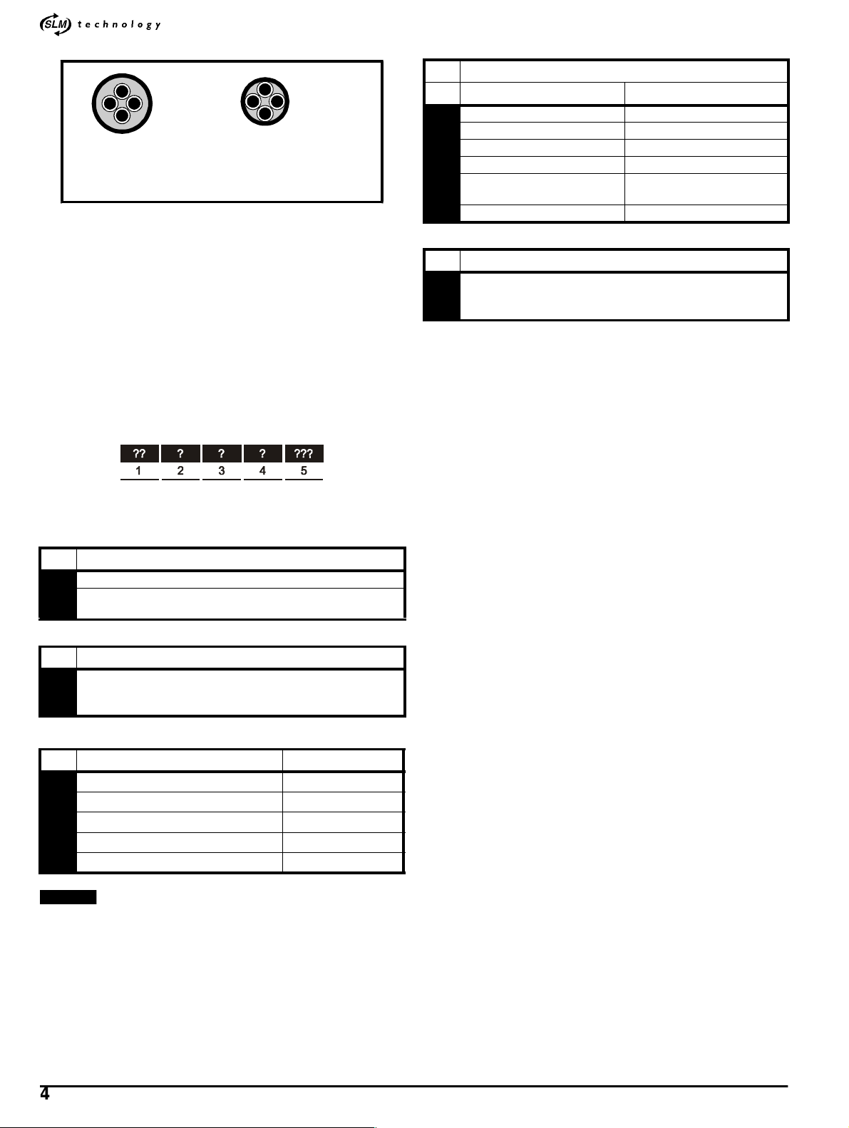
For identification, see Figure 2-1.
cable sizes for power input and output wiring. In the
event of a conflict, local regulations prevail.
Model
M’Ax403
M’Ax406
M’Ax409
M’Ax412
Model
M’Ax403
M’Ax406
M’Ax409
M’Ax412
Model
Input cable Output cable
1.5mm
2.5mm
4.0mm
4.0mm
Input cable Output cable
16 AWG
14 AWG
12 AWG
12 AWG
Cable size
2
2
2
2
1.0mm
1.0mm
1.5mm
2.5mm
2
2
2
2
Cable size
18 AWG
16 AWG
14 AWG
14 AWG
Maximum cable length *
mft
M’Ax 403 50 165
M’Ax 406 50 165
M’Ax 409 50 165
M’Ax 412 50 165
M’Ax Installation Guide 3
Issue Number: 6 www.controltechniques.com
Page 8
*
Figure 2-1 Cable construction influencing the capacitance
Normal capacitance
Shield or armour
separated from the cores
Parallel connection of DC buses
When a number of drives are used in a system, it is possible to connect
their DC buses in parallel in order to allow energy sharing, especially
when one or more motors are being braked. Operation in this manner is
not coveredby this Installation Guide; cable sizes and otherinformation
can be obtaine from the supplier of the drive.
High capacitance
Shield or armour close
to the cores
4 Cable terminations
For connection to the drive For connection to the motor
A Termination ferrules 6-way size-1 plug
C Termination ferrules Termination ferrules
K Termination ferrules 6-way s ize-1.5 plug
L Cut ends 6-waysize-1.5 plug
T ermination ferrules / Ring for
M
M’Ax
6-way size-1 plug
X Cutends Cut ends
5 Cable length
Specify length in metres
Minimum: 002 (2 metres)
Maximum: 050 (50 metres)
Ordering motor cables
Cablesof the required lengths and type of sheath,and fittedwith
appropriate terminations to suit the drive and CT-Dynamics SL motors,
are supplied by Control TechniquesD ynamics Ltd. For ordering, create
the required ordercode (see below)and contact the supplierof the drive.
The order code is constructed as follows:
See opposite for the details of the code.
1 Number of conductors
PS 3-phase + ground
3-phase + ground
PB
+ motor-brake control
2 Type of sheath
PUR
B
Use for dynamic applications (motor mounted on a moving
structure) – increased oil resistance
Example
PSBAM010
10m Unimotorconnection to ferrules power cable for a dynamic
application
3 Conductor size (phases and ground) Current rating
G
A
B
C
D
NOTE
The values stated are for 40
2
1.5mm
2
2.5mm
2
4.0mm
2
6.0mm
2
10.0mm
o
C ambient free air applications.
16A
22A
30A
39A
58A
Information should only be used for reference.
4 M’AxInstallationGuide
www.controltechniques.com Issue Number: 6
Page 9
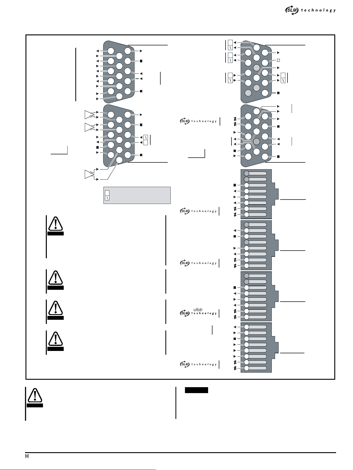
2.6 Signal cables and connectors
5
2
1
43543216785
432
167854321678678543210
H
D
c
0
2
H
D
0
2
2
E
2
H
D
c
c
5
c
c
1
2
4
3
H
B
M
M
Figure 2-2 Plan view of top of drive: Locations of the terminals and their connector
*
Digital I/O
Frequency input
Quad. A input
Direction input
Quad. B input
Hardware enable
Digital output 4
0V COMMON
SLM-and-user
back-up supply
Touch-trigger
Output 1
Input 1
Output 2
Input 2
Output 3
Input 3
Output 4
Input 4
Input 5
Input 6
+24V
input
5
10
4
9
3
8
2
7
1
6
5
10
4
9
3
8
2
7
1
6
Non-inverting input/output
Inverting input/output
Terminate pulse reference inpu t
connections (frequency / direction or
quadrature inputs) at the drive by
CAUTION
connecting across the related input
terminals a resistor whose value equals the
characteristic impedance of the cable that
is being used. When more than one drive is
connected a resistor is required only at the
last drive.
0V and 0V common must be used only in
conjunction with their related signal
connections, and must not be used in place
CAUTION
of each other.
Any cable connecting to the SIM ENC
connector should have its cable shield
connected to Pin 15. Failure to d o so can
CAUTION
result in damage to the drive.
Wait30 secondsafter removing power to
the drive before inserting or removing
control cables as ‘hot plugging’ cables can
CAUTION
result in damage to the drive or SLM.
DIGITAL I/O SIM ENC
15
14
13
12
11
15
14
13
12
11
24V user supply
0V COMMON
Input 7
Input 8
0V COMMON
24V user supply
0V COMMON
0V COMMON
STANDALONE MC/EIA485
Digital I/O
High-precision
analog input
Standard-precision
*
SLM-and-user
back-up supply
*
*
ultidrop
**
ultidrop
*
output
A output
analog input
om\
om\
Hardware enable
Status-relay
contact
0V COMMON
+24V
V COMMON
24V SLM supply
ardware enable
Drive-status supply
com\
com\
24V user supply
0V COMMON
ardware enable
rive-status supply
om\
com\
V COMMON
4V loopsupply
ardware enable
rive-status output
IA232
ardware enable
rive-status input
om\
com\
32 TXD
32 RXD
V COMMON
4V loop input
om\
com\
6
11
7
12
8
13
9
14
10
15
6
11
7
12
8
13
9
14
10
15
Analog output 1
0V
Analog output 2
Z output
Cable shields
TX
EIA 485
TX\
24V user supply
0V COMMON
RX
EIA 485
RX\
0V COMMON
SLM
MC
MULTIDROP
OUT
MULTIDROP
IN/PC
WARNING
Isolation
The signal connections are isolated from the power
circuits by basic insulation only. Ensure that all external
control circuits connected to this connector are
separated from human contact by at least one layer of
insulation rated for use at the AC supply voltage.
NOTE
0V connections
Do not connect 0V COMMON to 0V, or use these in place of each
other; doing so may cause instability in use. See Functions of the
signal terminals in Chapter 2 of the M’Ax User Guide.
M’Ax Installation Guide 5
Issue Number: 6 www.controltechniques.com
Page 10
*
2.7 RJ45 connectors and cables
RJ45 connectors
For connection to the following connectors on the drive...
•SLM
•MC
• MULTIDROP OUT
• MULTIDROP IN/PC
... use the following:
Cables
Up to four twisted-pairs having an overall shield (unused wires must not
be connected to pins at the other end)
Maximum length: 50m (165ft)
Maximumdiameter:6.6mm (
Static installations:for example, use BICC type S-FTP patch,four
twisted pairs, 5.33mm diameter
1
/4in)
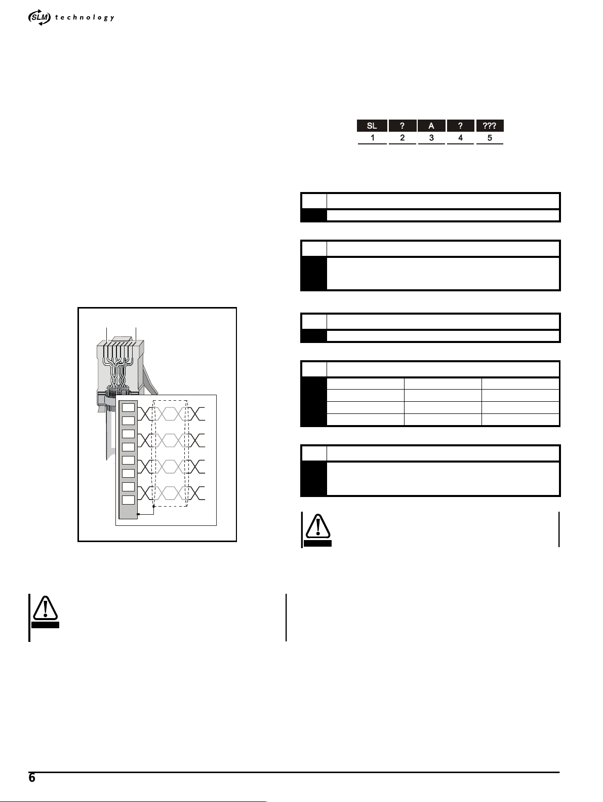
Ordering signal cables
Cablesof the required lengths and fitted with RJ45 connectors as
required are supplied by Control Techniques Dynamics Ltd. For
ordering, create the required order code (see below) and contact the
supplier of the drive.
The order code is constructed as follows:
Details of the code are as follows:
1Typeofcable
SL Two twisted pairs in overall shield
Dynamic installations: for example, use Intercond type 3MBM 26P 02P,
2 twisted pairs, 5.5mm diameter
Connectors
Shielded 8-way RJ45 plugs
18
1
2
3
4
5
6
7
8
Connectthe pinsin pairs as shown.
Comb out the braided shield, fold the strands back and trap them under
the cable clamp to ensuregood electrical contact with the clamp.
2Typeofsheath
PUR
B
Use for dynamic applications (motor mounted on a moving
structure) – increased oil resistance
3 Options
A Standard
4 Cable terminations
F RJ45 plug 5-way Din connector Drive to SLM
G RJ45 plug Cut end
K RJ45 plug RJ45 plug Drive to drive
X Cut end Cut end
5 Cable length
Specify length in metres
Minimum: 002 (2 metres)
Maximum: 050 (50 metres)
Wait 30 seconds after removing power to the drive before
inserting or removing control cables as ‘hot plugging’
CAUTION
cablescan result in damage to the drive or SLM.
Do not use unshielded plugs.
Use RS Component part no 290-4780 for shielded
WARNING
connector 5.7mm, or
Use RS Component part no 342-2087 for shielded
connector 6.6mm
6 M’AxInstallationGuide
www.controltechniques.com Issue Number: 6
Page 11
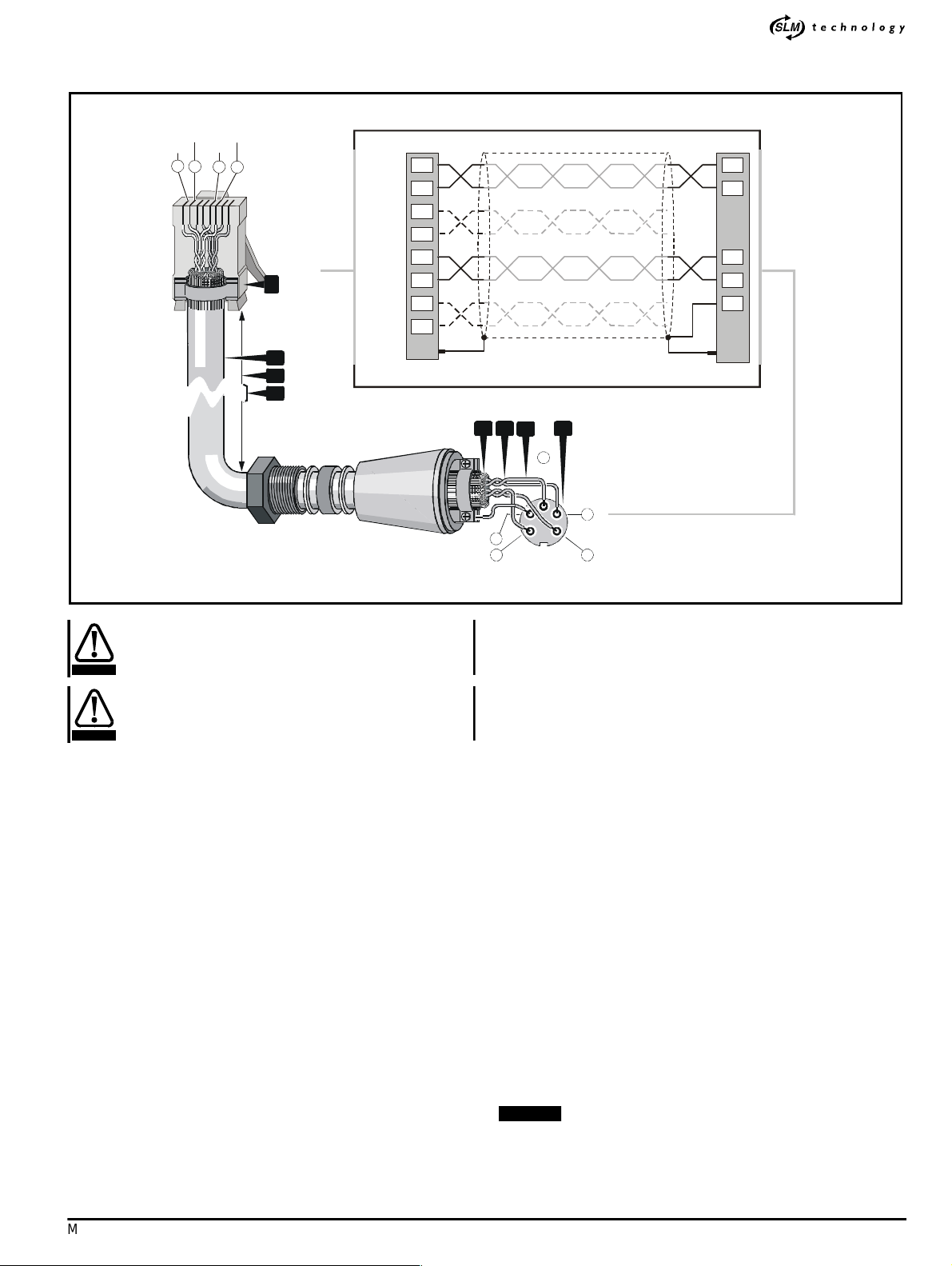
2.8 SLM connector
2
3
10V+
c
7
SLM(
Figure 2-3 Connecting the SLM cable to the connectors (only the relevant parts of the connectors are shown)
com\
com
1
0V
+24V
1
2
6
5
Drive
(RJ45)
8
com
com/
+24V
0V
2
3
4
5
6
7
8
*
5
1
3
2
4
1
2
3
Drive
Incorrect wiring of this cable could result in failure of the
WARNING
M’Ax or SLM.
Wait 30 seconds after removing power to the drive before
inserting or removing control cables as ‘hot plugging’
CAUTION
cablescan result in damage to the drive or SLM.
1. 8-way shielded cable having an overall diameter not greater than
1
6.6mm(
/4in)
2. Maximum length: 50m (165ft)
3. Route the cable by the shortest convenient path and so that it is no
closerthan 300mm (1ft) from any powercable.
4. Overall shield of tinned copper braid. Comb out the braid at both
ends, fold the strands back and trap them under thecable clamp to
ensuregood electrical contactwith the connector shell.
5. The required twisted pairs connected to the DIN connector, the
unwanted twisted pairs should be cut at each end and insulated to
prevent inadvertent contact.
6. Make the wire ends as short as possible (this affects performance).
7. AmphenolC091 31D005 100 2 5-way screw-locking DIN connector
meetingIP67.
8. Shielded RJ45 8-way plug
2.9 D-type connectors
For connection to the following connectors on the drive...
•SIMENC
• MC/EIA485
• DIGITAL I/O
• STANDALONE
... use the following:
SLM
54
6
24V
0V
4
5
com
om/
DIN)
Cables
Manyof the signalsare EIA485 comms.and thesemust use twisted
pairsof the correct characteristicimpedancecables having tinnedcopperstranded conductors, overallbraidedshield
Maximum overall diameter:dependson the D-typeconnector being
used
Connectors
SIM ENC
MC/EIA485
15-wayhigh-density male D-type having a metalshell (improved
EMC type)
DIGITAL I/O
STANDALONE
15-wayhigh-density female D-typehaving a metal shell (improved
EMC type)
2.10 Method of mounting
The two mounting brackets fittedto the driveare intended for mounting
the drive on the back-plate of the enclosure. Exhaust heat from the drive
is emitted in front of the back-plate. (Mounting instructions are given
laterin this chapter.)
Alternativelythe drivecan be mounted through an aperture in the backplate to allow the exhaust heat t o be emitted behind the back-plate.I n
this case, the two mounting brackets fitted to the drive must be removed,
modified and re-fitted; the ground bracket supplied with the drive must
also be modified.For instructions, refer to the supplier of the drive.
2.11 Output current,Ambient temperature, Heat dissipation, De-rating
NOTE
Theambienttemperature shouldbe taken as the temperature of the
air immediately under the drive. This is especially important when
the drive is to be installed above heat-generating equipment.
M’Ax Installation Guide 7
Issue Number: 6 www.controltechniques.com
Page 12

*
The drive can supply the rated maximum continuous output current
(FLC) as follows...
ModelsM’Ax 403 and M’Ax 406: Up to an ambient temperature of
55°C (131°F)
ModelsM’Ax 409 and M’Ax 412: Up to an ambient temperature of
45°C (113°F); from 45°C to 55°C (131°F), the maximum permissible
continuous output currentis reducedto 8.5A and 10.5A respectively.
2.13 When to use a braking resistor
When an AC motor is decelerated,or the drive is preventing the motor
from gaining speed due to mechanical influences, energy is returned to
the drive from the motor. When this energy is too great for the drive to
absorb, the DC-bus voltage is raised, which increases the possibility of
the drive trippingdue to excessive DC-bus voltage.
If the driveis to be used at an altitude in excess of 2000m (6600ft), deratingfor altitude must be appliedto the output current; see Altitude on
page 26.
Make a note of the following values for the model to be used; you will
need to know theselater:
• Maximum intended ambient temperature (T
max) (required for
AMB
calculating the enclosure size later in thischapter)
• Maximum continuous output current(if this needs to be a de-rated
value)
• Maximum heat dissipated into the enclosure
Current de-rating
If this precaution is not taken, the output current of the
drivecan exceedthe maximum permissible value. This
CAUTION
may result in loss of motor control due to excessive
heatsink temperature causing the drive to trip.
2.12 Thermal protection
The power output stage (IGBT bridge) of thedrive is protectedas
follows:
• When the heatsink temperature reaches an alarm level the drive
continues operating;the lower line of thedisplayindicates hot as a
pre-warning
• Ifthe load is not reducedand the heatsinktemperaturecontinues to
rise the drive will trip; the lower line of the display indicates O.ht2
Depending on the braking requirements, an internal braking resistor
fitted in the drive, or an external braking resistor, can be used for
absorbingthe returned energy. Thebraking resistoris t hen switchedinto
circuitby an internaltransistor when theDC-busvoltagereaches 780V.
The required value for the braking resistor is determined by the
maximum required braking torque, while the required power rating is
determined by the amount of energy to be dissipated, the duty cycle and
repetition time, as well as the cooling available for the resistor. When the
valueand power rating havebeencalculated,a decisioncan be made to
use the internal resistoror an external resistor.
It is important that the brakingresistor is adequately
ratedo therwise the drive could trip due to excessive DCbus voltage; braking will then cease, allowing the motor
CAUTION
to coast uncontrolled.
2.14 Braking resistor data
Table 2-9 Internal braking resistor
Value 75Ω
Operating voltage (V
)
R
Peak current rating 10.9A
Peak power rating 8.9kW
Maximumcontinuous braking power 125W
780V at switch-on
760V at switch-off
Table 2-8 Maximum currents and heat dissipated into the
enclosure (these do not show de-ratingfor altitude)
Maximumheat
Output current
dissipated into
enclosure
Model
T
AMB
max.
Maximum
continuous
Maximum
overload
(2 secs.
max.)
Using
internal
braking
resistor
enclosure
o
55
M’Ax403
M’Ax406 55
M’Ax409
M’Ax412
(131
(131
45
(113
55
(131
45
(113
55
(131
C
o
o
C
o
o
C
o
o
C
o
o
C
o
o
C
o
3.5A 7.0A 250W 100W
F)
6.5A 13.0A 290W 140W
F)
9.5A 19A
F)
8.5A 17.0A
F)
12.5A 25A
F)
10.5A 21A
F)
330W 180W
350W 200W
Using
external
braking
resistor
mounted
outside
the
Table 2-10 External braking resistor
Absoluteminimum permissible
value
Operating voltage (V
)
R
Maximum possible braking current
(through 40Ω)(Ib
MAX
)
40Ω
780V at switch-on
760V at switch-off
20.5A
Peak power rating for 40Ω 16.8kW
Continuous power rating
(See Braking-resistor example
calculations later in this chapter)
The instantaneouspowerratingrefers to the power dissipated during the
conducting periods (milliseconds) of the braking transistor (this operates
undera form of pulse width modulation during braking).Higher
resistance values require proportionately lower instantaneous power
ratings.
The required averagepower rating of (and heat dissipated by) the
braking resistor depends on the duty cycle of the application (see 2.17
Braking-resistor example calculations on page 9).
8 M’AxInstallationGuide
www.controltechniques.com Issue Number: 6
Page 13

2.15 Braking resistor precautions
Electric shock risk
The voltages present on the braking resistor, its
WARNING
WARNING
associated components and terminals on the driveare
capable of inflicting a severe electric shock and may be
lethal.
Thermal overload protection
When an external braking resistor is used, it is essential
that a thermal overload protection device is incorporated
in the braking-resistor circuit in order to minimise the
risk of fire in the event of unexpectedly high current, or
loss of control of the braking circuit. A typical protection
circuit is shown in the following section, Thermal
protection of the braking resistor.
2.16 Thermal protection of the braking resistor
High temperatures
Braking resistors can attain high temperatures and
WARNING
When a braking resistor is to be used, ensure the following:
• Include a lock-out circuit that will prevent the AC supply from being
• An external braking resistor should be capable of tolerating thermal
• It is essential that the instantaneous and average power ratings of
• Whenan external braking resistoris mounted insidethe enclosure,
• Always use shielded or steel wire armoured cable for connecting an
When an external braking resistoris used, a thermal-protectioncircuit
must be added. This must disconnectthe AC supplyfromthe drive if the
brakingresistorbecomes overloaded. For guidance,Figure2-4 showsa
typical circuit arrangement (complete circuit diagrams for the power
connections appear later in this chapter).
When the internal braking resistor is used, a thermal-protection circuit is
not requiredsince thermal-modelling in the drivecauses the drive to trip
if the r esistor becomesoverloaded (trip code: It.br); also, the braking
resistor itself is fail-safe.
should be segregated from temperature-sensitive
equipment and personnel.
re-connected to the driveuntilthe cause of a trip has been fully
investigated.
shock; pulserated resistors are recommended.
the braking resistor are sufficientfor the most extreme braking duty
that is likely to be encountered. If the internalbraking resistoris
overloaded, the drive will trip (trip code: It.br).
or the i nternal braking resistoris used, the heat dissipated by the
resistor will increase the ambient temperature inside the enclosure.
(The value of heatdissipationis used forcalculating the enclosure
size or ventilation which are described later in this chapter.)
external braking resistor.
*
Figure2-4 Typical protection circuit for an external braking
1. START/RESET switch (momentary)
2. STOP switch (latching)
3. Control-circuit supply
4. Contactor coil
5. Thermal overload protectionrelay
6. External braking resistor
7. 380 ~ 480V AC supply to the drive
8. Drive power connectors.
2.17 Braking-resistor example calculations
Conditions
Model:M’Ax409
Maximum peak output current (Ipk) from the drive (for 2 seconds
maximum): 1 9A
Full-load speed (n)ofmotor:4000RPM
Continuous stall torque (T
Motor K
Motorinertia(J
Loadinertia(JL): 10.29 x 10⁻³kg m
Total inertia (JT= JM+ JL): 13.7 x 10⁻³kg m
Required deceleration time (td) from full to zero speed: 0.5 second
Repeat cycle time for deceleration (t
Minimump ermissiblebraking-resistorvalue: 40Ω
Operating voltage(V
=1.6Nm/A
T
M
): 3.43 x 10⁻³kg m
) at switch on: 780V
R
resistor
)ofmotor:12.2Nm
CS
2
2
): 7 seconds
r
2
M’Ax Installation Guide 9
Issue Number: 6 www.controltechniques.com
Page 14

*
R
2.18 Minimum permissible deceleration time
The minimum permissible decelerationtime is limited by thefollowing:
• The peak current of the drive (Ipk)
•Theintermittent torque limit of the motor (the value of torque that the
motor can deliver for a specified time - see the motor manufacturer’s
data)
1. Calculate the maximum torque that the motor would produce when
the drive is delivering peak current (19A), as follows:
M
bDRIVEIpkKT
Thedrivewouldcausethisvalueoftorquetobeproducedforupto2
seconds.
2. Refer to the the motor manufacturer’s data to obtain the permissible
overload (continuous stall torque) for 2 seconds.
Then use this figure to calculate the intermittenttorque limit for the
motorfor a 2-second duration.For this example,3 times thenominal
torquerating is assumed,as follows:
M
bINTTCS
3. For calculating the minimum permissible deceleration time (t
use the lower of the two calculated values, as follows:
M
bMAX
4. The followingequation is usedas thebasisfor the calculations:
M
b
Usethefollowingderivativeof the equationto calculatethe minimum
permissible deceleration time (t
load speed:
=
t
bMIN
× 19 1.6× 30.4Nm===
3× 12.2 3× 36.6Nm===
30.4Nm=
JTn
π
------ ----
----- -
30
b
JTπn
------ ----------- -------- -
30M
bMAX
Nm()×=
t
) for stopping the motor fromfull-
bMIN
bMIN
),
2.19 Power rating of the braking resistor
1. Calculate the kinetic energy (EK) that will be dissipated in the
braking resistor, as follows:
2
n π×
æö
E
0.5 J×
K
0.5 13.7× 10
E
K
E
1.2kJ=
K
2. Calculate the average power over deceleration time (td):
E
------ -
=
P
PK
td
1.2kJ
---------------
P
PK
3. Calculate the average power (P
whole cycle:
E
------ -
P
=
av
tr
1200
------ ------ -
P
av
When the value ofPavis less than 125W, the internal braking
resistor can be used. For this example (which shows marginal
conditions), an external braking resistor must be used in order to
reduce the risk of the drive tripping under braking; tripping would
remove control from the motor, allowing it to coast.
4. Since brakingis planned to occurintermittently, an external resistor
can be ratedfor intermittent rather than continuouspower
dissipationso that the overload factor of the resistor can be used.
This factor can beobtained fromcooling curves for theresistor, as
shown in Figure 2-5.
Figure 2-5 Example cooling curves for power resistors (in
practice, refer to the cooling curves for the resistor to be used)
×=
K
0.5
K
7
Overload
factor
------ ------ -
èø
30
3– 4000 π×
æö
××=
èø
2.4kW==
171W==
------ ----------- -----
2
30
) that will be dissipated over the
av
epeat cycle times
10
9
8
7
6
5
4
3
2
1
7s 1min5min
30s 30min
13.7 103–×π× 4000×
t
----- ----------- ----------- ----------- ----------- ---------- -
bMIN
Check that t
30 30.4×
is less than td;ifnot,systemdesignmustbe
bMIN
0.19 ondsec==
reconsidered.
Resulting torque
Calculatethe torquethat resultsfromtherequired decelerationtime,
as follows:
JTn
π
M
b
M
b
----------
------ ----
× Nm()=
30
t
d
13.7 103–×π× 4000×
------ ----------- ----------- ----------- ----------- -------- -
0.5 30×
11.5Nm==
0.1 0.2 0.5 1 2 5 10 20 50
Deceleration time
5. The coolingcurves indicatethat for a brakingtime of 0.5 second and
repeatcycletimeof7seconds,theoverloadfactor(F)is3.5.
10 M’AxInstallationGuide
www.controltechniques.com Issue Number: 6
Page 15

6. Calculate the minimum required power rating of the resistor, as
follows:
P
RMIN
P
----------
PK
F
×
2.4 10
------- ----------- ----- -
3.5
3
0.7kW== =
If the braki ng resistor is tobe mounted inside the enclosure,make a
note of this value;you will need it whencalculating the enclosure
size.
In practice,use a resistor having a powerrating higher than the
calculated value. For thisexample: P
=750Wor0.75kW
R
*
2. Select a model of thermal overload relay that can be set at 1.9A
3. Calculate the maximum current that could flow througha resistor
(e.g. due to the braking resistor becoming short circuit), as follows:
V
780
R
------ -
------- -- -
I
Rpk
R
4. Calculate the overload factor for this condition, as follows:
I
Rpk
---------------
F
===
S\C
I
SET
5. Use the tripping curves to findthe time that thethermaloverload
relay will take to trip (e.g. 30 seconds approximately).
200
3.9
------- - 2
1.9
3.9A== =
2.20 Value of the braking resistor
1. Calculate the maximum suitable value for the braking resistor, as
follows:
2
V
()
R
MAX
------ -------- -
P
PK
R
2
780
------ ------------ ----- -
2.4 10
×
3
250Ω== =
2. Inpractice,usearesistorhavingapreferredvalueclosetoand
lowerthan the calculated value.This is becausethecalculatedvalue
would cause the braking transistor to be switched on almost
continuouslyduringbraking.In this case, the drive will nothave full
controlof the DC-bus voltage.A lower value of braking resistor will
causethe brakingtransistorto act as a chopper whichwillthen allow
the drive to control the DC-bus voltage m ore accurately.
The reduction in value does not increase the power dissipation since
the average voltage across the resistor is reduced by the braking
transistor operatingas a chopper.
For this example: R=200Ω
2.21 Disabling protection of the internal
braking resistor
The internalbrakingresistor is protected against I2toverloadby
calculationsperformed in the drive software. When an externalbraking
resistorbeingused,thiscalculationmustbedisabledinordertoremove
the possibility of it causingthe drive to trip unnecessarily.
Balancedoperation 3-phase,
from cold state
Balancedoperation 2-phase,
from cold state
Balancedoperation 3-phase,
Time (s)
aftera long period of set current
flow (hot state)
100
50
20
10
5
2
1
0.5 1 2 5 10 17
X current setting
(F)
2.23 Enclosure layout
Refer to Figure 2-6 for minimumclearances above and belowthedrive.
The bookcase format allows drives to be mountedin rows withno need
for horizontal spacing.
Figure 2-6 Minimum clearances above and below the drive
Todisable the I
2
t protection for the internalbraking resistor,make a note
to set parameter 10.55at 1 whenfollowingChapter6 Setting Up the
drive for Basic Applications in the UserGuide.
Do not disable the I
2
t protection when the internal
braking resistor is to be used.
CAUTION
2.22 Currentsetting for a thermal overload
protection relay
1. Calculate the maximum permissible continuous current through
the brakingresistor that is to be used, as follows:
P
750
R
------- -- - 1.9A== =
I
Rmax
------ -
200
R
where:
P
is the continuouspower rating of the resistor to be used ( not
R
the minimum requiredpower rating)
R is the actual value of the braking resistor (not the calculated
value)
M’Ax Installation Guide 11
Issue Number: 6 www.controltechniques.com
Refer to Figure 2-7 for the arrangement of the associated equipment and
wiring in the enclosure. This diagram shows two drives, one having an
external brakingresistor connected. When EMC emission standards are
to be met, an RFI filter will need to be included for each drive; see the
sections on EMC emission standards later in this chapter.
Page 16

*
Figure 2-7 Arrangement of the drive and associated equipment in
the enclosure
EMC compliance
When compliance with EMC emission standards is required, additional
precautions must be taken; see the EMC emission standards sections
laterin this chapter.
2.24 Clearances for the signal cables
Recommendedclearances areshown on this page;theyarerequiredfor
routine EMC precautions as well as for compliance with EMC emission
standards.
Clearance from the drive
Do not locate sensitive
signalcircuits or pass
signalcableswithin
300mm(12 in) of the drive.
1. Enclosure. For high ingress protection, this must be sealed and the
drive mounted on the back-plate.
2. Enclosure back-plate.
3. When an external braking resistor is to be used, mount the resistor
either above or inside the enclosure, as follows...
Inside Locate theresistor on or near the top panel.
Outside Mount the resistor in an adequately ventilatedmetal
housing that will prevent inadvertent contact with the resistor.A
separate external braking resistor must be used for each drive
(unless their DC-buses are connected in parallel).
4. Thermal overload protection relay required for each external braking
resistor. Locate as required.
5. System controller. Locate as required.
6. Signal cables and circuits. See the next section in this chapter for
clearances.
7. Drivemountedverticallyon the enclosure back-plate (see 1. above).
8. Power cables.P osition as required.
9. Isolator, contactor, and fuses or MCBs. Locate as required.
10. Alternative locationso f fuses or MCBs. Locate asrequired.
11. Power cables entering the enclosure. Position as required.
Clearance from power
cables
Do not pass signal cables
within300mm (12 in) of:
• Motor cables
• Braking resistor
cables
• AC supply cables
12 M’AxInstallationGuide
www.controltechniques.com Issue Number: 6
Page 17

Crossing angle
When power and
signalcables
cross,the
crossing angle
must be 90°.
*
Total heat dissipation
1. Add the dissipation figures from step 6 (in Planning the installation)
for each drive thatis to be installedin the enclosure. Make a note of
the total value.
2. IfanRFIfilteristobeusedwitheachdrive,addthedissipation
figures from step 29 (in EMC emissionstandards – instructionslater
in this chapter) for each RFI filter that is to be installed in the
enclosure. Make a note of the total value.
3. If the braking resistoris to be mounted inside the enclosure,add the
average power dissipation from step 12 (in Planning the installation)
foreachbraking resistorthat is to be installedin the enclosure.Make
a note of the total value.
4. Make a note of the total heat dissipation(in Watts) of any other
equipment to be installed in the enclosure.
5. Add the heat dissipation figures obtained (as appropriate) from lines
1, 2, 3 and 4 above. This gives a figure in Watts for the total heat that
will be dissipatedinside the enclosure. Make a note of thisfigure.
Calculating the size of a sealed enclosure
The enclosuretransfers internally generatedheat into the surrounding
air by natural convection(or external forced air flow);the greaterthe
surface area of the enclosure walls, the better is the dissipation
capability. Only the surfaces of the enclosure that are unobstructed (not
in contact with a wall or floor) can dissipate heat.
Calculate the minimum required unobstructed surface area A
enclosure from:
P
------ ----------- ----------- -----
=
A
e
kT
–()
iTamb
Where:
Unobstructed surface area in m2(1m2= 10.8ft2)
A
e
T
Maximum expected ambient temperature in °C outside the
amb
enclosure
T
Maximumintended ambient temperaturein °C insidethe
i
enclosure
P Power in Watts dissipated by all heat sources in the
enclosure
k Heat transmission coefficientof the enclosure material
in W/m
2
/°C
for the
e
2.25 Enclosure calculations for heat removal
Decidewhether the enclosure is to be sealed or ventilated, asfollows:
Sealed enclosure
Asealedenclosurecangiveahighingress-protectionrating,butwith
reduced heat removal capabilities. If possible, locate heat-generating
equipment (other than braking resistors) in the lower part of the
enclosure to encourage internalconvection. If necessary, a taller
enclosure, and/or air-circulation fans inside the enclosure, can be used.
For calculating the minimum size of sealed enclosure that will
adequately cool the drive(andother drives),see Enclosure calculations
later in this chapter.
Ventilated enclosure
If a high ingress-protection rating is not required, a ventilated enclosure
canbeusedwithafantosupplyforcedaircooling;thiscangivealower
ambient temperature than asealed enclosure. For calculating the
minimum requiredvolume of coolingair, see Calculating the air-flow in a
ventilated enclosure on page 14.
NOTE
Take care when performing these calculations in order to ensure
the ambient temperature inside the enclosure does not exceed
55°C (131°F)or 45°C (113°F), as appropriate (see step 6 in Planning
the installation).
Example
Tocalculate the size of an enclosure for the following:
• Three M’Ax409
• Each driveis to have an externalbrakingresistormountedinside the
enclosure
• AnRFI filter (model 3258-16-45) to be used witheach drive
• Maximum ambient temperature inside the enclosure: 55°C
• Maximum ambienttemperature outsidethe enclosure:30°C
Dissipation of the drive:180W (from section 2.11Output current,
Ambient temperature, Heat dissipation, De-rating on page 7)
Average dissipation from the braking resistor: 171W (fromsection
2.18 Minimumpermissible deceleration time on page 10)
Dissipation of each RFI filter: 6W (max) (from Installing an RFI filter on
page 21
T otal dissipation: 3 x (180 + 171 + 6) = 1071W
The enclosure is to be made from painted 2mm (0.0787in) sheet steel
havinga heat transmissioncoefficientk of 5.5W/m
front, and two sides of the enclosure are to be free to dissipate heat.
2
/°C. Only the top,
M’Ax Installation Guide 13
Issue Number: 6 www.controltechniques.com
Page 18

*
Figure 2-8 Enclosurehaving front,sides and top panels free to
dissipate heat
P
0
k
Ratio of
p
----- -
P
1
Where:
is the air pressureat sea level
P
0
P
is the air pressureat the installation
1
Typicallyuse a factor k
drops in dirty air-filters.
of1.2to1.3,toallowalsoforpressure-
a
H
D
W
Insertthe following values:
T
55°C
i
T
30°C
amb
k 5.5
P 1071W
The minimum required heat conducting area is then:
(1m
A
e
2
=10.8ft2)
1071
------- ----------- ----------- --- -
5.5 55 30–()
7.8
2
84ft2()==
Estimate two of the enclosuredimensions- the height(H)and depth(D),
for instance. Calculate the width (W) from:
A
2HD–
e
------ ----------- -------- -
=
W
HD+
Inserting H = 2mand D = 0.6m, obtain the minimum width:
7.8 2 2× 0.6×()–
----- ----------- ----------- ----------- --------
W
20.6+
2.08m 6ft10in()==
If the enclosure is too large for the spaceavailable, it can be made
smaller only by attendingto one or all of the following:
• Reducing the ambient temperature outside the enclosure, and/or
applying forced-air cooling to the outside of the enclosure
• Removingotherheat-generating equipment, eg. braking resistors
• Reducingthe number of drives in the enclosure
• Aircirculating fan insideenclosure (see section 2.25 Enclosure
calculations for heat removal on page 13)
Example
T ocalculate the required air flow in an enclosure for the following:
• ThreeM’Ax409
• Eachdrive is to have an external brakingresistor mounted outside
the enclosure
• Maximum ambient temperature inside the enclosure: 55°C
• Maximum ambient temperature outside the enclosure: 30°C
•Atsealevel(k
=1forthisexample)
p
Dissipation of each drive: 180W (from section 2.11 Output current,
Ambient temperature, Heat dissipation, De-rating on page 7)
T otal dissipation: 3 x 180 = 540W
Insert the following values:
T
55°C
i
T
30°C
amb
k
1.3
a
P 540W
Then:
31.3× 540×
------ ----------- ----------- ----- -
V
55 30–
84m
3
hr 493min()==
Calculating the air-flow in a ventilated enclosure
The dimensions of the enclosure are required only for accommodating
the equipment. The equipment is cooled by the forced air flow.
Calculate the minimum requiredvolumeof ventilating air from:
3kP
------ ----------- ------- -
V
=
T
–
iTamb
Where:
3
V Air-flow in m
T
Maximum ambientt emperaturein °C outsidethe enclosure
amb
per hour
Ti Maximum ambient temperaturein °C inside the enclosure
P Power in Watts dissipated by allheat sourcesin the
enclosure
14 M’AxInstallationGuide
www.controltechniques.com Issue Number: 6
Page 19

2.26 Mounting the drive
Parts supplied
Quantity Part Purpose
1 M5 nut
Ground stud1 M5 plain washer
1 M5springwasher
1 Groundbracket Safetygroundconnections
3 Hose clip (11 to 16mm[0.433to 0.630 in] dia.) Clamppower cables to the ground bracket
2 Keyed plug-in 4-way connector
1 Keyed plug-in5-way connector andbraking link
1 Upper mountingbracket
1 Lower mountingbracket
4 M4 x 8mm T20Torx-head Taptite screws
Fitting the mou nting brackets to the drive
Figure 2-9 Locations of the mounting brackets
Power connections
Mounting the drive
*
1. Locatethe tabsof the upper mountingbracket (not fittedwith a stud)
in the slots near the top of the rear panel of thedrive.
2. Retain the bracket with two of the M4 T20 Torx-head screws
supplied.
3. Locate the tabs of the lower mounting bracket (fitted with stud S)in
the slots near the bottom of the rear panel of the drive.
4. Retain the bracket with two of the M4 T20 Torx-head screws
supplied.
M’Ax Installation Guide 15
Issue Number: 6 www.controltechniques.com
Page 20

*
(
(
(
2.27 Attaching the drive to the back-plate
Figure 2-10 Mounting details for the drive
M5
9.724in)
11mm (0.433in)
14.173in)
(0.590in)
(1.986in)
M5
12.992in)
(10.748in)
(0.787in)
(0.905in)
(2.440in)
1. Back-plate with mounting holes A.
2. Upper mounting bracket fitted to the rear of the drive.
3. Lower mounting bracket with M5 stud S fitted to the rear of the drive.
The stud must be used for ground termination (see section
2.30 Method of connecting the power cables on page 18).
4. If compliance with EMC emission standardsis required, both
mountingbracketsmust make direct electricalcontact with the backplate;the screw holes should be threaded.
5. Area occupied by thedrive.
6. Looselyfit screws (B), locate the slotted holes in the mounting
brackets over the screws, then tighten the screws.
16 M’AxInstallationGuide
www.controltechniques.com Issue Number: 6
Page 21

2.28 Precautions for making power connections
Electric shock risk
The voltages present in the following locations can
WARNING
WARNING
WARNING
WARNING
causesevereelectricshockandmaybelethal:
• AC supply cables and connections
• Output cables and connections
• Many internal parts of the drive
• An auxiliary back-up supply when connected in
addition to the AC supply.
Isolation device
The AC supply must be disconnected from the drive
using an approved isolation device before any coveris
removed from the drive or before any servicing work is
performed.
Stored charge
The drive contains capacitors that remain charged to a
potentiallylethal voltage after the AC supply has been
disconnected. If the drive has b een energised, the AC
supply must be isolated at least five minutes before work
may continue.
AC supply by plug and socket
Special attentionmust be givenif the driveis installed in
equipment which is connected to the AC supply by a
plugand socket.TheAC supplyterminalsof the driveare
connected to the internal capacitors through rectifier
diodes which do not giveisolation. If the plug terminals
can be touched when the plug is d isconnectedfrom the
socket, a means of automatically isolating the plug from
the drive must be used (eg. a latching relay).
*
2.29 Terminal sizes and tightening torques
To avoid a fire hazard and maintain validity of the UL
listing, adhere to the specified tightening torques for the
WARNING
RFI filter
power and ground terminals. Refer to the following
tables.
Power terminals Ground terminal
Unit
Drive
Size
Type
Plug-in
terminal
block
Screw
terminals
Torque Size
Type
0.5N.m
4.4lb.in
0.7N.m
6.2lb.in
M5 stud
Screw
terminals
Torque tolerance ±10%
Torque
2N.m
17.7lb.in
0.7N.m
6.2lb.in
WARNING
WARNING
STOP function
The STOP function does not remove dangerous voltages
from the drive.
Safety ground connection
The ground loop impedance must conform to the
requirements of local safety regulations.
The electrical safety of the installation depends on the
correct fitting and use of the ground bracket supplied
with the drive. All ground connections to the drive must
be made to this ground bracket.
The ground bracket must be grounded by a connection
capable of carrying the prospective fault current until the
protective device (fuse, etc) disconnects the AC supply.
The ground connections must be inspected and tested at
appropriate intervals.
M’Ax Installation Guide 17
Issue Number: 6 www.controltechniques.com
Page 22

*
0
W
L
W
2.30 Method of connecting the power cables
Figure 2-11 Locations of the power connections and correct fitting of the ground bracket
ARNING
V
ive circuit dedicated
isolated supply is
required.
20mm (0.787in)
5
The and 0V terminals are not connected together
inside the drive. It is essential that the ground
WARNING
For electrical safety, thegroundbracketmust be fitted as shown.S ee
alsosection2.31 Circuitdiagramsfor the power connections on page 19
and section 2.29 Terminalsizes and tighteningtorqueson page 17.
Perform all of the following:
1. Fit a plug-in multi-wayconnector into eachof the threesockets on
2. Loosenthe screwfor each of the ground terminals of the 4-way
3. Fit the two tongues of the ground bracket in the ground terminals of
4. Fit onto the groundstud the M5 plain washer,spring washer and nut
connections from the AC supply and to the motor are
made to the ground bracket as shown.
the undersideof the drive. These connectors are keyed to ensure
correct fitting.
connectors.
the 4-way connectors and pass the hole in the upright section (as
viewed in the diagram) of the ground bracket over the ground stud in
the lower mounting bracket.
supplied with thedrive.While tightening the nutt o the specified
torque, ensure the tongues on the ground bracket remain fully
inserted in the terminals.
12mm (0.472in)
Ground bracket must
be fitted due to risk
ARNING
5. Tighten the screwsin the two groundterminals to thespecified
torque.
6. Strip back the insulating sheath on the shielded cablesto expose at
least 12mm (0.472in)of shield and 30mm (1.181in) of inner
conductors.
7. Fit a hose clip over each cable shield to clamp it to the ground
bracket; for reliable contact, it may be necessary to wrap copper foil
aroundthe shield.
8. Connect the ground wire of the motor cable to the ground bracket
usingthe related hole at thepositionshown. This applies whether
thegroundwireisinsideoroutsidethecable.
When an external braking resistor is used,use the same
arrangement for the brakingresistor cable.
9. UseacabletietosecuretheACsupplywiringtothegroundbracket.
10. If an auxiliary back-up supply is to be connected, ensure its output is
isolated and it is connected only to terminals H and
back-upsupplies in Chapter 2 Connecting the drive in the User
Guide.
of electric shock
−;seeTypes of
18 M’AxInstallationGuide
www.controltechniques.com Issue Number: 6
Page 23

*
0
2.31 Circuit diagrams for the power connections
Figure 2-12 Power connections to be made when an external braking resistor is used, including a typical protection circuit for the
braking resistor
Key to Figure
1. START/RESET switch
2. STOP switch
3. Control supply
4. Contactor coil
5. Thermal overload protection relay
6. Brakingresistor
7. AC supply to the drive
8. AC supply Isolator
V
M’Ax Installation Guide 19
Issue Number: 6 www.controltechniques.com
Page 24

*
0
Figure 2-13 Power connectionsto be made when the internal braking resistor is used
Key to Figure
1. START/RESET switch
2. STOP switch
3. Control supply
4. Contactor coil
5. AC supply to the drive
6. AC supply isolator
7. Link to connect the internal braking resistor
V
20 M’AxInstallationGuide
www.controltechniques.com Issue Number: 6
Page 25

2.32 EMC emission standards compliance information
NOTE
*
EN 50081-2, use an RFI filter for each drive,as shown in Table 2-11 .
(Standards that aremet are specif ied in AppendixB Data on page 26.)
Table 2-11 RFI filter details
Conditions for EMC compliance
The installer of the drive is responsible for ensuring compliance
with the EMC regulations that apply where the drive is to be used.
The drive will comply with thestandards for emission, such as
EN50081-2, only when the instruct ions given in this section are
adhered to closely.
Special note for EN61800-3 (EMC Power Drive Systems)
For installation in the‘secondenvironment’, i.e. where the low
voltage supply network does not supply domestic premises, and
wheretheratedinput current of the drive system exceeds100A, no
filter is required in order to meet IEC61800-3 (EN61800-3).
Operating the drive in this environment without an EMC filter may
cause interference to nearby electronic equipment whose
sensitivity has not beenappreciated.The user must take remedial
measures if this situation arises.
If the consequencesof unexpected disturbances are severe, it is
recommended that the emission limits of EN50081-2 be adhered to.
In any other case, adhere to the precautions described in this
section.
When the drive is used in the ‘first environment’, i.e. where the low
voltage supply network also supplies domestic premises, the following
warning applies:
Thisis a productof restricted distribution class
according to IEC61800-3. In a domestic environment this
WARNING
product may cause radio interference in which case the
user may be required to take adequate measures.
RFI filter
Model
M’Ax 403 4200-1645 4200-0081 6W IP20
M’Ax 406 4200-1645 4200-0081 6W IP20
M’Ax 409 4200-1645 4200-0081 6W IP20
M’Ax 412 4200-1645 4200-0081 6W IP20
MakeanoteofthefollowingforeachRFIfiltertobeused:
• Part number
• Maximum power dissipation figure
•IPrating
Dimensions of the bookcase RFI filter
LWH J B CG T
250 45 70 220 25 235 5.4 1.0 mm M5
9.842 1.772 2.776 8.661
Dimensions of the footprint RFI filter
LWHJBCGT X
360 54.5 40 273 N/A 330 5.5 1.0 mm M5
14.173 2.156 1.575 10.748 N/A 12.992 0.216 0.039 in
Bookcase
filter part
number
Footprint
filter part
number
9.252
0.984
Maximum
power
dissipation
0.039
0.2
Ingress
protection
in
X
3
/
16
3
/
16
2.33 EMC emission standards instructions
Follow these instructions in addition to those given earlier in this chapter.
Enclosure
The enclosure must be made of metal but does not require specialEMC
features.
Back-plate
Ensure the enclosure back-plate is unpainted, but it may be zinc plated.
Mounting brackets electrically connected to the back-plate
Ensurethe mounting brackets for the driveand RFI filter make direct
electrical connection with the back-plate.
Grounding
For compliance with EMC emission standards, employ the grounding
arrangements shownin thissection.These arrangementsare in addition
to (not instead of) the safety requirements.
The fittingof an additional safety ground will not reduce the EMC
performance.
External braking resistor
When an external braking resistor is to be mounted outside the
enclosure, ensure the following:
• The resistorhousing will giveelectromagnetic shielding(without
compromising ventilation)
• The braking-resistor wiring must be shielded/armoured
WARNING
The filter has a high leakage current to ground. A
permanent fixed ground connection must be provided.
Installing an RFI filter
For compliance with emission standards such as EN 50081-1 or
M’Ax Installation Guide 21
Issue Number: 6 www.controltechniques.com
Page 26

*
2.34 Clearances from the RFI filter and AC supply cables
1. Mount the RFI filter as close as
possible to thedrive. No
clearance is required either
side of the RFI filter or the
drive.
2. Make the wires connecting the
RFI filter to the drive as short
as possible.
3. Allow at least 100mm (4 in)
clearance (C) between the AC
supplycableand the following:
• Signalcables
•Drive
• Braking resistors and cables
• Motorsand cables
2.35 Additional ground connections for the signal cables
Electrically bond the shieldsof all thesignal cablesto the back-plate by
direct grounding unless ground-loop currents cause problems if the drive
is controlled by an analog speed reference. In this case, indirect
grounding can be used to ground all the cables except the cable
connected to the SIM ENC connector; this mustalwaysbe directly
grounded.
Refer to the next two diagrams.
22 M’AxInstallationGuide
www.controltechniques.com Issue Number: 6
Page 27

Direct grounding
1. Using an uninsulatedmetal cable-clamp(1), electrically bond the
shield (2)of the cable to the back-plate (3).
2. Ensure there is no more than 250mm(10 in) of cablelength(4)
between the clamp and the drive.
(Forclarity, the upper mounting brackethas been omitted from this
view.)
*
Indirect grounding
Indirect grounding uses a 10nFcapacitor to prevent low-frequency
ground-loop currents from occurring; these can cause problems in
systems controlled by analog signals.
1. Use insulatingstuds (5)to mount an uninsulated metalplate (6) on
the back-plate(3); the plate (6) must be insula ted fromthe backplate.
2. Using uninsulated metal cable-clamps (1), electrically bond the
shield (2) of each cable to the metal plate (6).
3. Ensure there is no more than 250mm(10 in) of cablelength(4)
between each clamp and the drive. (Refer to the preceding
diagram. )
4. Connect a 10nF 2kV ceramic disc capacitor (7) between the metal
plate(6) and the back-plate (3). Maximum permissiblelength of
each lead-outwireis 20mm(0.787in).
M’Ax Installation Guide 23
Issue Number: 6 www.controltechniques.com
Page 28

*
2.36 Bonding the cable shield to the motor frame
The shield of themotor cable must be electricallybonded to the motor
frame. The preferred method of achieving this is to connect the shield to
the ground terminalof the motor, as shown in the following two
diagrams.
For motors that have a power
inputsocket,a metal cable
plug should be used and the
cable shieldmake contact
withthe shell throughoutits
entire circumference (full 360°
termination). (A typicalplugis
shownopposite. )
If a full 360° termination is not
possible (due to a plastic plug
being used, or the motor
having separate terminals and
cable glands), a link no
longer than 25mm (1 in)
between the shield and the
terminal should be
used.
0V
24 M’AxInstallationGuide
www.controltechniques.com Issue Number: 6
Page 29

Appendix A UL Listing
Information
The drive conforms to UL listingrequirements onlywhen the following
are observed:
• The drive is installedin a t ype 1 enclosure,or better, as defined by
UL50
• UL-listed fuses class CC 600VAC are used in the AC supply
• Class 1 60/75°C (140/167°F) copper wire only is used in the
installation
• The ambient temperature does not exceed 40°C (104°F) when the
driveis operating
• The terminal tightening torques specified in section 2.29 Terminal
sizes and tightening torques on page 17 are used
A.1 AC supply specification
The drive is suitable for use in a circuit capable of delivering not more
than 5000 RMS symmetrical Amperes at 528VACRMS maximum.
A.2 Maximum continuous output current
The drive models are listed as having the maximum continuous output
currents (FLC) shown in Table A-1.
*
Table A-1 Maximum continuous output current
Model FLC (A)
MAX403SL
MAX403AN
MAX406SL
MAX406AN
MAX409SL
MAX409AN
MAX412SL
MAX412AN
3.5
6.5
9.5
12.5
M’Ax Installation Guide 25
Issue Number: 6 www.controltechniques.com
Page 30

*
Appendix B Data
B.1 M’Ax Data
Output current ratings
Output c urre nt
Model
M’Ax403
M’Ax406
M’Ax409
M’Ax412
* Models M’Ax 409 and M’Ax 412 only
For operation up to 55°C (131°F), the value of parameter 4.07 Current
limit must be reduced. If this precaution is not taken, the output current
of the drive can exceed the maximumpermissible value.This mayresult
in loss of motor control due to excessive heatsink temperature causing
the drive to trip.
T
AMB
Maximum
55°C
(131°F)
55°C
(131°F)
45°C
(113°F)
55°C
(131°F) *
45°C
(113°F)
55°C
(131°F) *
Maximum
continuous
3.5A 7.0A
6.5A 13.0A
9.5A 19A
8.5A 17.0A
12.5A 25A
10.5A 21A
Output current to be used for cable sizing
Model
M’Ax 403 5A
M’Ax 406 9A
M’Ax409 12A
M’Ax412 15A
Current values to be used
for rating motor cables
Maximum
overload
(2s max.)
For operation on an AC supply in a poorer category, refer to the supplier
of the drive for adviceon suitablevaristors to connect to theAC supply.
Refer also to Altitude later in this Appendix.
Temperature, humidity and cooling method
Ambient temperature range:
Models M’Ax403,M’Ax406
0°C to 55°C (32°F to 131°F) at rated maximum continuous output
current (FLC)
Models M’Ax409,M’Ax412
0°C to 45°C(32°F to 113°F)at rated maximum continuous output
current (FLC); from 45°C (113°F) to 55°C (131°F), the maximum
permissible continuous output current is reduced
(See Output current ratings earlier in thisAppendix)
Cooling method: Internal fan
Maximum humidity: 95% non-condensing at 55°C (131°F)
Storagetemperature range: –40°C to 55°C (–40°F to 131°F)
Maximum storagetime:12 months
Altitude
Altitude range without derating:0 to 2000m ( 6600ft)
When additional precautions are taken, the drive can be operated at
altitudes from 2000m to 4000m (13000ft); for information, contact the
supplier of the drive.
Vibration
Random vibration according to IEC 68–2–34
2
/Hz over 5 to 20 Hz, reducing at –3dB/octavefrom 20 to 500
0.01g
Hz (0.89g RMS) applied for 30 minutes in each orthogonal axis
Ingress protection
IP20
Suitable for use in a Pollution Degree 2 environment
Overall dimensions
H Height includingmounting brackets
WWidth
D Projection forward of panel when surface mounted
Supplycurrents
Model
M’Ax 403 6.0A 9.8A
M’Ax 406 9.3A 15.0A
M’Ax 409 11.9A 19.4A
M’Ax 412 13.9A 23.0A
NOTE
Maximum supply currents apply to an AC supply having 2%
negative phase-sequence and a fault current of 5kA.
Maximum continuous
supply current
Maximumoverload
supply current
AC supply requirements
380V to 480V ±10%
3-phase
47.5 to 63Hz
Maximum supply imbalance:2% negative phase sequence (equivalent
to 3% voltage imbalance between phases)
Over-voltage categories
The drive can be operated on AC supplies in the following (or better)
over-voltage categories...
Grounded star supply:
Over-voltage category 3
Grounded delta and IT supplies:
Over-voltage category 2
Dimensions
H 360mm 14.173in
W 62mm 2.440in
D 247mm 9.724in
Weight
Model size 1: 3kg (6.6lb)
Dissipation
Maximum heat dissipated into enclosure
Model
M’Ax 403 250W 100W
M’Ax 406 290W 140W
M’Ax 409 330W 180W
M’Ax 412 350W 200W
Using internal
braking resistor
Starts per hour
By electroniccontrol: unlimited
By interrupting the AC supply: <
20
Using external
braking resistor
26 M’AxInstallationGuide
www.controltechniques.com Issue Number: 6
Page 31

SLM-and user back-up supply input
Voltage:24V ±20%
Maximum current: 500mA
A current limit in excess of 500mA can result in
damage to the M’Ax.
CAUTION
Auxiliary back-up supply input
Voltage:27VDC ~ 32VDC (Operationoutside these limits will result in
damage to the drive
Maximum current: 1A
This supplyis referencedto –DC. For isolation requirements,see Types
of back-upsupplies in Chapter 2 Connecting the M’Ax in the User Guide.
Fora recommendedauxiliary back-upsupply, contact the supplier of the
drive.
An auxiliary back-up supply must be isolated from
ground and any other auxiliary back-up supply.
Failure toobservethese requirements will result in
CAUTION
damage.
24V user supply outpu t
Voltage:24V+20%
Maximum current: 400mA - lo
Where Io is the total current being drawn from the following:
• Digital outputs
• Drive-status supply
*
Electromagnetic compatibility (EMC)
This is a summary of the EMC performance of the drive when installed in
accordance with the instructions given in Chapter 2 Installing the drive .
Refer to section 2.32 EMC emission standards - compliance
information on page 21. For full details,t he M’Ax EMC Data Sheet can
be obtainedfrom a DriveCentreor distributor listed at the end of this
guide.
Immunity
Compliance with immunity standards does not depend on installation
details. The drive meets EN50082–2 (generic immunity standard for the
industrial environment) and the following specifications from the
IEC61000–4 group (derived from IEC801):
Part2, Electrostatic discharge: Level 3
Part 3, Radio frequency field: Level 3
Part 4 Transien t burst:
Level 4 at the control terminals
Level 3 at the power terminals
Part 5, Surge (at the AC supply terminals):
Level 4 line-to-ground
Level 3 line-to-line (as specified by EN50082–2 informative
annex)
Part 6, Conducted radio frequency: Level 3
Emission
Compliance with emission standards depends on rigorous adherence to
the installation guidelines, including the use of the specified RFI filterin
the AC supply circuit. Compliancealso depends on the length of the
motor cable. For full details, refer to the M’Ax EMC Data Sheet which
canbeobtainedfromaDriveCentreordistributorlistedattheend
of this guide.
Braking resistor
Internal resistor
Value 75Ω
Operating voltage (V
Peak current rating 10.9A
Peak power rating 8.9kW
Maximumcontinuous braking power 125W
External resistor
Absoluteminimum
permissible value
Operating voltage (V
Maximum possible braking
current(through 40Ω)(I
Peak power rating for 40Ω 16.8kW
Continuous power rating
)
R
)
R
)
bMAX
(See Braking-resistorexample
780V at switch-on
760V at switch-off
40Ω
780V at switch-on
760V at switch-off
20.5A
calculationson page 9)
Summary
Conducted and radiated emission meet EN50081–2 (generic emission
standard for the indust rial environment) over a wide range of conditions.
This is similar to CISPR11 and EN55011 Class A.
The optionalRFI filter, part number 3258-16-45, must be used.
Complian ce with EN61800–3 (standardfor Power Drive Systems)
Meetingthe requirements of this standard dependson the environment
that the drive is to be operated in, as follows:
Operation in the first environment
Observe the wiringguidelines given in the whole of Chapter 2 Installing
the drive , includingthe section 2.32 EMC emission standards -
compliance informationon page 21.
Operation in the second environment
Where the rated input current of the drive system is less than 100A:
Observe the wiring guidelines given in the whole of Chapter 2 Installing
the drive , includingthe section 2.32 EMC emission standards -
compliance informationon page 21.
Where the rated input current of the drive system exceeds 100A:
Observe the wiringguidelines in Chapter 2 Installing the drive ,
excluding the section 2.32 EMC emissionstandards - compliance
information on page 21.
The second environment typically includes an
industrial low-voltage powersupply network which
does not supply buildings used for domestic purposes.
CAUTION
Operating the drive in this environment without an RFI
filter may cause interference to nearby electronic
equipment whose sensitivity has not been appreciated.
The user must take remedial measures if this situation
arises.
If the consequences of unexpected disturbances are
severe,it is recommended thatthe emission limits of
EN50081–2 be adhered to.
M’Ax Installation Guide 27
Issue Number: 6 www.controltechniques.com
Page 32

*
B.2 Optional RFI filter data
Main ratings
Part number 4200-1645 4200-0081
Max. continuous current 16A 16.5A
Power dissipation at rated current 6W 6W
Maximum a mbient temperatureat rated current and frequency range:
50°C (122°F)
Ingress protection: IP20
AC supply ratings
Maximum operating voltage:480V at up to 50°C(122°F)
AC supply frequency:48 to 62 Hz
Ground leakage current
Ground-leakage current phase-to-phase and phases-to-ground is a s
follows:
Balanced supply, all phasespresent: 33mA
Two phases disconnected: 192mA
These figures apply foran AC supply of 400V at 50Hz. ForotherAC
supply voltages and currents, scale the values of leakage current
proportionally.
Discharge resistors
330KΩ star network between the AC supply phases; the star point is
connected by a 1MΩ resistor to ground.These resistorsare fitted
internally.
Maximum current overload
150% of rated current for 60 seconds.
RFI Filter Overall dimensions
CT Part
Number
4200-1645 FN3258-16-45
4200-0081 FS-5599-16-5-07*
* Dimensionswhen attachedto drive
Schaffner
Part Number
Height Width Depth kg lb oz
250mm
9.842in
360mm
14.173in
Dimension Weight
45mm
1.772in
54.5mm
2.145in
70mm
2.776in
287mm
114.299in
0.8 1lb12oz
1.4 3lb1oz
28 M’AxInstallationGuide
www.controltechniques.com Issue Number: 6
Page 33

Index
*
Numerics
24V user supply output ...........................................................27
A
AC supply by plug and socket .................................................17
AC supply disturbances . ...........................................................3
AC supply protection .................................................................2
AC supply ratings ....................................................................28
AC supply requirements ..........................................................26
AC supply specification ...........................................................25
Air-flow in a ventilated enclosure .............................................14
Ambient temperature .................................................................7
Auxiliary back-up supply input .................................................27
B
Braking resistor .........................................................................8
Braking resistor - example calculations .....................................9
Braking resistor - power rating ................................................10
Braking resistor - thermal protection .........................................9
Braking resistor - value of ........................................................11
Braking resistor data .................................................................8
C
Cable capacitance .....................................................................3
Cable shield- bonding to the motor frame ..............................24
Cable type and size ...................................................................3
Cautions ....................................................................................1
Compliance with regulations .....................................................1
Cooling method .......................................................................26
Current overload - maximum ...................................................28
Currents - maximum ..................................................................8
D
DC buses - parallel connection .................................................4
Deceleration time - minimum permissible ...............................10
De-rating ...................................................................................7
Dimensions - overall ................................................................26
Discharge resistors ..................................................................28
Dissipation ...............................................................................26
Drive clearances .....................................................................12
D-type connectors . ....................................................................7
G
Ground conductors ................................................................... 3
Ground leakage current .......................................................... 28
Grounding - direct ...................................................................23
Grounding - indirect ................................................................ 23
H
Hazardous areas ...................................................................... 2
Heat dissipation ....................................................................7
Heat dissipation - total ............................................................ 13
Humidity .................................................................................. 26
, 8
I
Installation considerations ........................................................ 2
Installation in an enclosure ....................................................... 2
Internal braking resistor ............................................................ 8
Internal braking resistor - disabling protection ........................ 11
Isolation device ....................................................................... 17
L
Line reactor values ................................................................... 3
Line reactors ............................................................................. 3
M
Model sizes and versions .........................................................2
Motor ........................................................................................ 1
Motor cable ............................................................................... 3
Motor cables - ordering ............................................................. 4
Mounting brackets .................................................................. 15
Mounting details ..................................................................... 16
Mounting method ...................................................................... 7
Mounting the drive ..................................................................15
N
Notes ........................................................................................ 1
O
Output current ........................................................................... 7
Output current- maximum continuous ................................... 25
Output current ratings ............................................................. 26
Over-voltage categories ......................................................... 26
E
Electric shock risk ....................................................................17
Electricalsafety - general warning ............................................1
Electromagnetic compatibility ....................................................2
EMC compliance .....................................................................12
EMC emission standards - complianceinformation ................21
EMC emission standards - instructions ...................................21
Enclosure - calculations for heat removal ...............................13
Enclosure layout ......................................................................11
Environmental ...........................................................................2
Environmental limits ..................................................................1
External braking resistor ............................................................8
F
Fire enclosure ...........................................................................2
Fuse ratings ..............................................................................3
M’Ax Installation Guide 29
Issue Number: 6 www.controltechniques.com
P
Power cables ............................................................................ 3
Power cables - connecting ..................................................... 18
Power cables clearances ........................................................ 12
Power connectioncircuit diagram ...........................................19
Power connections- precautions ...........................................17
Power connections- when external braking resistor is used .. 19
Power connections- when internal braking resistor is used ... 20
R
RFI filter - overall dimensions ................................................. 28
RFI filter clearances ................................................................ 22
RFI filter details ....................................................................... 21
RFI filter dimensions - bookcase ............................................ 21
RFI filter dimensions - footprint ............................................... 21
Risk analysis .............................................................................1
RJ45 connectors and cables .................................................... 6
Page 34

*
S
Safety ground connection .......................................................17
Safety of personnel ...................................................................1
Sealed enclosure - sizing ........................................................13
Signal cables - clearances ......................................................12
Signal cables - ground connections ........................................22
Signal cables - ordering ............................................................6
Signal cables and connectors . ..................................................5
SLM input ................................................................................27
Starts per hour ........................................................................26
STOP function .........................................................................17
Stored charge ......................................................................... 17
Supply currents .......................................................................26
System design ..........................................................................1
T
Temperature ........................................................................... 26
Terminal sizes .........................................................................17
Thermal overload protection relay - current setting ................11
Thermal protection ....................................................................8
Tightening torques ..................................................................17
U
UL Listing information .............................................................25
User back-up supply input ......................................................27
W
Warnings ...................................................................................1
Weight .....................................................................................26
30 M’AxInstallationGuide
www.controltechniques.com Issue Number: 6
 Loading...