

Conexant R6795 Datasheet

Doc. No. 1213, Rev. 1
January 20, 1999
5+'3&,
+RVW&RQWUROOHG9.IOH[
0RGHP'HYLFH)DPLO\IRU'HVNWRS$SSOLFDWLRQV
'HVLJQHU}V*XLGH
Conexant Proprietary Information
Dissemination or use of this information is not permitted
without the written permission of Conexant Systems, Inc.

RH56D-PCI Modem Designer’s Guide
ii
Conexant
1213
Conexant Proprietary Information
Information provided by Conexant Sys t ems, Inc. is believed to be accurat e and reliable. However, no responsibility is assumed by Conexant
for its use, nor any infri ngem ent of patents or other rights of third parties which may result from its use. No lic ense is granted by implicat i on or
otherwise under any patent rights of Conexant other than for circui t ry embodied in Conexant products. Conexant reserves the right to change
circuitry at any ti m e without notice. This docum ent is subject to change wit hout notice.
K56flex is a trademark of Conexant Systems, I nc. and Lucent Technologies.
Conexant and “What's Next in Comm uni cations Technologies” are trademark s of Conexant Systems , Inc.
Product names or servic es listed in this public ation are for identification purpos es only, and may be trademarks or regi stered trademarks of
their respective compani es. All other marks ment i oned herei n are the property of their respective owners.
©1999, Conexant Systems , Inc.
Printed in U.S.A.
All Rights Reserved

RH56D-PCI Modem Designer’s Guide
1213
Conexant
iii
Conexant Proprietary Information
Table of Contents
1. INTRODUCTION................................................................................................................................................. 1-1
1.1 SUMMARY............................................................................................................................................... 1-1
1.2 FEATURES.............................................................................................................................................. 1-3
1.3 TECHNICAL OVERVIEW......................................................................................................................... 1-6
1.3.1 General Description...................................................................................................................1-6
1.3.2 Host Modem Software................................................................................................................ 1-6
1.3.3 Operating Modes........................................................................................................................ 1-6
Data/Fax Modes................................................................................................................ 1-6
Synchronous Access Mode (SAM) - Video Conferencing................................................. 1-6
Voice/TAM Mode............................................................................................................... 1-7
Speakerphone Mode (SP Model)...................................................................................... 1-7
1.3.4 Hardware Interfaces................................................................................................................... 1-7
PCI Bus Host Interface...................................................................................................... 1-7
Serial EEPROM Interface ................................................................................................. 1-8
Audio Interface.................................................................................................................. 1-8
Telephone Line/Telephone/Audio Interface...................................................................... 1-8
2. TECHNICAL SPECIFICATIONS ........................................................................................................................ 2-1
2.1 ESTABLISHING DATA MODEM CONNECTIONS................................................................................... 2-1
Dialing............................................................................................................................... 2-1
Modem Handshaking Protocol.......................................................................................... 2-1
Call Progress Tone Detection........................................................................................... 2-1
Answer Tone Detection..................................................................................................... 2-1
Ring Detection................................................................................................................... 2-1
Billing Protection ............................................................................................................... 2-1
Connection Speeds........................................................................................................... 2-1
Automode.......................................................................................................................... 2-1
2.2 DATA MODE............................................................................................................................................ 2-1
Speed Buffering (Normal Mode) .......................................................................................2-1
DTE-to-Modem Flow Control............................................................................................. 2-1
Escape Sequence Detection............................................................................................. 2-1
GSTN Cleardown (V.90/K56flex, V.34, V.32 bis, V.32)..................................................... 2-2
Fall Forward/Fallback (V.90/K56flex, V.34/V.32 bis/V.32)................................................ 2-2
Retrain............................................................................................................................... 2-2
2.3 ERROR CORRECTION AND DATA COMPRESSION............................................................................. 2-2
V.42 Error Correction........................................................................................................ 2-2
MNP 2-4 Error Correction ................................................................................................. 2-2
V.42 bis Data Compression .............................................................................................. 2-2
MNP 5 Data Compression ................................................................................................2-2
2.4 FAX CLASS 1 OPERATION..................................................................................................................... 2-2
2.5 VOICE/TAM MODE.................................................................................................................................. 2-2
2.5.1 Online Voice Command Mode................................................................................................... 2-2
2.5.2 Voice Receive Mode.................................................................................................................. 2-3
2.5.3 Voice Transmit Mode................................................................................................................. 2-3
2.5.4 Speakerphone Modes................................................................................................................ 2-3
2.6 FULL-DUPLEX SPEAKERPHONE (FDSP) MODE.................................................................................. 2-3
2.7 CALLER ID............................................................................................................................................... 2-3
2.8 MULTIPLE COUNTRY SUPPORT........................................................................................................... 2-3
2.8.1 OEM Programmable Parameters............................................................................................... 2-3
2.8.2 Blacklist Parameters.................................................................................................................. 2-3
2.9 DIAGNOSTICS......................................................................................................................................... 2-4
2.9.1 Commanded Tests..................................................................................................................... 2-4
2.10 LOW POWER SLEEP MODE...................................................................................................................2-4

RH56D-PCI Modem Designer’s Guide
iv
Conexant
1213
Conexant Proprietary Information
3. HARDWARE INTERFACE ................................................................................................................................. 3-1
3.1 HARDWARE SIGNAL PINS AND DEFINITIONS..................................................................................... 3-1
3.2 POWER REQUIREMENTS AND MAXIMUM RATINGS.........................................................................3-13
3.3 MDP ELECTRICAL CHARACTERISTICS.............................................................................................. 3-14
3.4 PCI BUS ELECTRICAL, SWITCHING, AND TIMING CHARACTERISTICS.......................................... 3-14
4. DESIGN CONSIDERATIONS............................................................................................................................. 4-1
4.1 PC BOARD LAYOUT GUIDELINES......................................................................................................... 4-1
4.1.1 General Principles...................................................................................................................... 4-1
4.1.2 Component Placement............................................................................................................... 4-1
4.1.3 Signal Routing............................................................................................................................ 4-2
4.1.4 Power......................................................................................................................................... 4-3
4.1.5 Ground Planes........................................................................................................................... 4-4
4.1.6 Crystal Circuit............................................................................................................................. 4-4
4.1.7 VC and VREF Circuit ................................................................................................................. 4-4
4.1.8 Telephone and Local Handset Interface.................................................................................... 4-5
4.1.9 Optional Configurations ............................................................................................................. 4-5
4.1.10 MDP Specific.............................................................................................................................. 4-5
4.2 CUSTOM DESIGN GUIDELINES FOR 2-LAYER PCI MODEM BOARD................................................. 4-5
4.2.1 General Guidelines.................................................................................................................... 4-5
4.2.2 Placement of Modem Devices ................................................................................................... 4-6
4.2.3 Trace Routing and Length on PCI Signals................................................................................. 4-6
4.2.4 Grounding.................................................................................................................................. 4-6
4.2.5 Filtering...................................................................................................................................... 4-6
4.2.6 Decoupling................................................................................................................................. 4-7
4.2.7 Crystal Circuit............................................................................................................................. 4-7
4.2.8 Modem Analog Interface............................................................................................................ 4-8
4.3 PCB LAYOUT EXAMPLES
....................................................................................................................... 4-9
4.4 CRYSTAL/OSCILLATOR SPECIFICATIONS ........................................................................................4-11
4.5 OTHER CONSIDERATIONS.................................................................................................................. 4-11
4.6 PACKAGE DIMENSIONS....................................................................................................................... 4-14
5. SOFTWARE INTERFACE.................................................................................................................................. 5-1
5.1 PCI CONFIGURATION REGISTERS....................................................................................................... 5-1
5.1.1 0x00 - Vendor ID Field............................................................................................................... 5-1
5.1.2 0x02 - Device ID Field................................................................................................................ 5-1
5.1.3 0x04 - Command Register......................................................................................................... 5-2
5.1.4 0x06 - Status Register ............................................................................................................... 5-2
5.1.5 0x08 - Revision ID Field............................................................................................................. 5-3
5.1.6 0x09 - Class Code Field............................................................................................................. 5-3
5.1.7 0x0D - Latency Timer Register .................................................................................................. 5-3
5.1.8 0x0E - Header Type Field.......................................................................................................... 5-3
5.1.9 0x28 - CIS Pointer Register ....................................................................................................... 5-3
5.1.10 0x2C - Subsystem Vendor ID Register...................................................................................... 5-3
5.1.11 0x2E- Subsystem ID Register.................................................................................................... 5-3
5.1.12 0x34 - Cap Ptr............................................................................................................................ 5-3
5.1.13 0x3C - Interrupt Line Register.................................................................................................... 5-3
5.1.14 0x3D - Interrupt Pin Register...................................................................................................... 5-3
5.1.15 0x3E - Min Grant Register.......................................................................................................... 5-3
5.1.16 0x3F - Max Latency Register..................................................................................................... 5-3
5.1.17 0x40 - Capability Identifier ......................................................................................................... 5-3
5.1.18 0x41 - Next Item Pointer ............................................................................................................ 5-3
5.1.19 0x42 - PMC - Power Management Capabilities ......................................................................... 5-4
5.1.20 0x44 - PMCSR - Power Management Control/Status Register (Offset = 4)............................... 5-4
5.1.21 0x46 - PMCSR_BSE - PMCSR PCI to PCI Bridge Support Extensions..................................... 5-4
5.1.22 0x47 - Data ................................................................................................................................ 5-4

RH56D-PCI Modem Designer’s Guide
1213
Conexant
v
Conexant Proprietary Information
5.2 BASE ADDRESS REGISTER .................................................................................................................. 5-5
5.3 SERIAL EEPROM INTERFACE............................................................................................................... 5-6
5.3.1 Supported EEPROM Sizes........................................................................................................ 5-6
5.3.2 Definitions.................................................................................................................................. 5-7
Device ID Register............................................................................................................ 5-7
Vendor ID Register............................................................................................................ 5-7
Subsystem Vendor ID and Subsystem Device Register................................................... 5-7
Min_Gnt Register.............................................................................................................. 5-7
Max_Lat Register.............................................................................................................. 5-7
PMC [8:6], PME DRV Type............................................................................................... 5-8
CardBus CIS Pointer (CardBus CIS pointer High, CardBus CIS pointer Low).................. 5-8
Data Register (D3, D2, D1, D0 power consumed and D3, D2, D1, D0 power
dissipated)......................................................................................................................... 5-8
Load CISRAM Count (CIS _SIZE) .................................................................................... 5-8

RH56D-PCI Modem Designer’s Guide
vi
Conexant
1213
Conexant Proprietary Information
List of Figures
Figure 1-1. RH56D-PCI System Overview ............................................................................................................................... 1-4
Figure 1-2. RH56D-PCI Hardware Configuration Block Diagram............................................................................................. 1-5
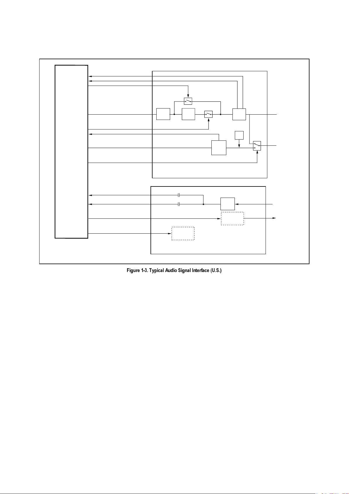
Figure 1-3. Typical Audio Signal Interface (U.S.)..................................................................................................................... 1-9
Figure 3-1. RH56D-PCI Major Hardware Interface Signals...................................................................................................... 3-2
Figure 3-2. R6795 144-Pin TQFP Hardware Interface Signals................................................................................................ 3-3
Figure 3-3. R6795 144-Pin TQFP Pin Signals.......................................................................................................................... 3-4
Figure 3-4. Schematic - R6795 Interface –Speakerphone Application................................................................................... 3-12
Figure 4-1. PCICLK Guard Band Technique............................................................................................................................ 4-9
Figure 4-2. Receive Path Guard-Band, Merge between AGND-GND...................................................................................... 4-9
Figure 4-3. Crystal Solution.................................................................................................................................................... 4-10
Figure 4-4. Power and Ground Distribution............................................................................................................................ 4-10
Figure 4-5. Package Dimensions - 144-Pin TQFP................................................................................................................. 4-14
List of Tables
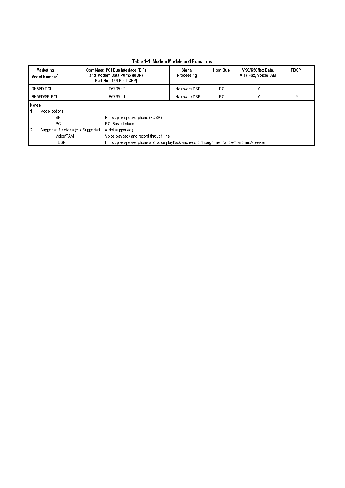
Table 1-1. Modem Models and Functions................................................................................................................................ 1-2
Table 1-2. Typical Signal Routing - Voice Mode .................................................................................................................... 1-10
Table 3-1. R6795 144-Pin TQFP Pin Signals ........................................................................................................................... 3-5
Table 3-2. R6795 Pin Signal Definitions................................................................................................................................... 3-7
Table 3-3. Current and Power Requirements......................................................................................................................... 3-13
Table 3-4. Absolute Maximum Ratings................................................................................................................................... 3-13
Table 3-5. Analog Electrical Characteristics........................................................................................................................... 3-14
Table 4-1. Crystal Specifications - Surface Mount ................................................................................................................. 4-12
Table 4-2. Crystal Specifications - Through Hole................................................................................................................... 4-13
Table 5-1. PCI Configuration Registers.................................................................................................................................... 5-1
Table 5-2. Command Register ................................................................................................................................................. 5-2
Table 5-3. Status Register........................................................................................................................................................ 5-2
Table 5-4. Power Management Capabilities (PMC) Register................................................................................................... 5-4
Table 5-5. Power Management Control/Status Register (PMCSR).......................................................................................... 5-4
Table 5-6. BIF Address Map..................................................................................................................................................... 5-5
Table 5-7. EEPROM Content for 256 Words by 16 Bits per Word........................................................................................... 5-6
Table 5-8. EEPROM Content for 128 Words by 16 Bits per Word........................................................................................... 5-6

RH56D-PCI Modem Designer’s Guide
1213
Conexant
1-1
Conexant Proprietary Information
1. INTRODUCTION
1.1 SUMMARY
The Conexant RH56D-PCI V.90/K56flex Host Controlled Modem Device Family supports high speed analog data up to 56
kbps, 14.4 kbps fax, voice/TAM, and speakerphone (optional) operation. The modem operates with PSTN telephone lines in
the U.S. and world-wide. The modem is available with or without speakerphone support (see Table 1-1).
The modem is packaged in a single 144-pin thin quad flat pack (TQFP) that combines PCI Bus Interface (BIF) and Modem
Data Pump (MDP) functions.
This modem is pin-compatible with the SoftK56-PCI modem, part number R6793 (see
SoftK56-PCI data sheet Order No. MD231).
Host modem software is also provided.
Operating with +3.3V power, this device set supports 32-bit host applications in such designs as embedded motherboards
and PCI half cards. Downloadable architecture allows updating of MDP executable code.
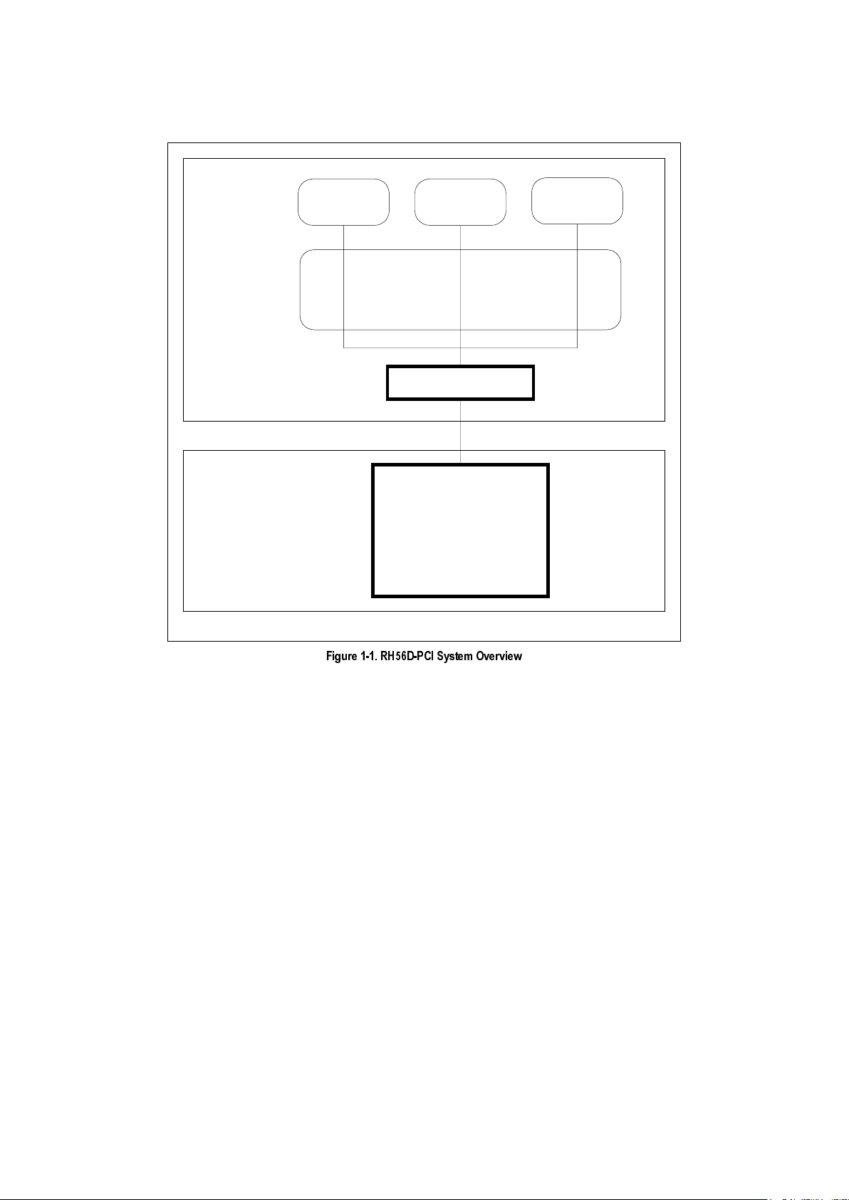
Figure 1-1 illustrates the general structure of the RH56D-PCI software and the interface to the RH56D-PCI hardware.
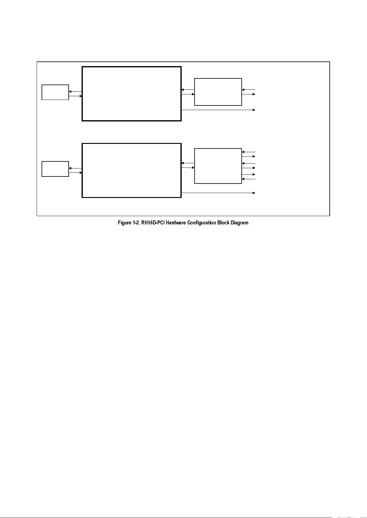
Figure 1-2 illustrates the major hardware interfaces supported by each model.
In ITU-T V.90/K56flex data mode, the modem can receive data at speeds up to 56 kbps from a digitally connected V.90 or
K56flex-compatible central site modem. A V.90/K56flex modem takes advantage of the PSTN which is primarily digital except
for the client modem to central office local loop and is ideal for applications such as remote access to an Internet Service
Provider (ISP), on-line service, or corporate site. In this mode, the modem can transmit data at speeds up to V.34 rates.
In V.34 data mode, the modem operates at line speeds up to 33.6 kbps. When applicable, error correction (V.42/MNP 2-4)
and data compression (V.42 bis/MNP 5) maximize data transfer integrity and boost average data throughput. Non-errorcorrecting mode is also supported.
All models support remote audio recording and remote audio playback over the telephone line interface using A-Law, µ-Law,
or linear coding at 8000 or 7200 Hz sample rate to support applications such as digital telephone answering machine (TAM).
The SP model supports position independent, full-duplex speakerphone (FDSP) operation.
Fax Group 3 send and receive rates are supported up to 14.4 kbps with T.30 protocol.
V.80 synchronous access mode supports host-controlled communication protocols, e. g., H.324 video conferencing.
Reference design kits are available to minimize application design time and costs.
This designer's guide describes the modem hardware capabilities and identifies the supporting commands. Commands and
parameters are defined in the Commands for RH56D/RC56HCF and RH56LD Reference Manual (Order No. 1118).
RH56D-PCI Modem Designer’s Guide
1-2
Conexant
1213
Conexant Proprietary Information
7DEOH 0RGHP 0RGHOV DQG )XQFWLRQV
0DUNHWLQJ
0RGHO 1XPEHU
&RPELQHG 3&, %XV ,QWHUIDFH %,)
DQG 0RGHP 'DWD 3XPS 0'3
3DUW 1R >3LQ 74)3@
6LJQDO
3URFHVVLQJ
+RVW %XV 9.IOH[ 'DWD
9 )D[ 9RLFH7$0
)'63
5+'3&, 5 +DUGZDUH '63 3&, < ²
5+'633&, 5 +DUGZDUH '63 3&, < <
1RWHV
0RGHO RSWLRQV
63 )XOOGXSOH[ VSHDNHUSKRQH )'63
3&, 3&, %XV LQWHUIDFH
6XSSRUWHG IXQFWLRQV < 6XSSRUWHG ± 1RW VXSSRUWHG
9RLFH7$0 9RLFH SOD\EDFN DQG UHFRUG WKURXJK OLQH
)'63 )XOOGXSOH[ VSHDNHUSKRQH DQG YRLFH SOD\EDFN DQG UHFRUG WKURXJK OLQH KDQGVHW DQG PLFVSHDNHU

RH56D-PCI Modem Designer’s Guide
1213
Conexant
1-3
Conexant Proprietary Information
1.2 FEATURES
•
Data modem
−
ITU-T V.90, K56flex, V.34 (33.6 kbps), V.32 bis, V.32, V.22 bis, V.22, V.23, and V.21; Bell 212A and 103
−
V.42 LAPM and MNP 2-4 error correction
−
V.42 bis and MNP 5 data compression
−
V.250 (ex V.25 ter) and V.251 (ex V.25 ter Annex A) commands
−
Fax modem send and receive rates up to 14.4 kbps ITU-T V.17, V.29, V.27 ter, and V.21 channel 2
−
EIA/TIA 578 Class 1 and T.31 Class 1.0 commands
•
Voice, telephony, TAM
−
V.253 commands
−
8-bit µ-Law/A-Law coding (G.711)
−
8-bit/16-bit linear coding
−
8000/7200 Hz sample rate
−
Music on hold from host or analog hardware input
−
TAM support with concurrent DTMF detect, ring detect and caller ID
•
V.80 synchronous access mode supports host-controlled communication protocols
−
H.324 interface support
•
V.8/V.8bis and V.251 (ex V.25 ter Annex A) commands
•
Full-duplex Speakerphone (FDSP) Mode (SP model)
−
Telephone handset interface
−
External microphone and speaker interface
−
Microphone gain and muting
−
Speaker volume control and muting
−
Adaptive acoustic, line, and handset echo cancellation
−
Loop gain control, transmit and receive path AGC
•
Data/Fax/Voice call discrimination
•
Multiple country support
−
Call progress, blacklisting
•
Single profile stored in host
•
Modem and audio paths concurrent across PCI Bus
•
System compatibilities
−
Windows 95, Windows 95 OSR2, Windows 98, Windows NT 4.0, Windows NT 5.0 operating systems
−
Microsoft's PC 98 Design Initiative compliant
−
Unimodem/V compliant
−
Pentium 133 MHz equivalent or greater
−
16 Mbyte RAM or more
•
32-bit PCI Local Bus interface
−
Conforms to the PCI Local Bus Specification, Production Version, Revision 2.1
−
PCI Bus Mastering interface to the MDP
−
33 MHz PCI clock support
•
Supports PCI Bus Power Management
−
Conforms to PCI Bus Power Management Specification, Rev. 1.1
−
ACPI Power Management Registers
−
APM support
−
PME# support
•
Device package
−
R6795 Modem: 144-pin TQFP (1.6 mm max. height)
•
+3.3V operation with +5V tolerant digital inputs
•
+5V or +3.3V analog operation
RH56D-PCI Modem Designer’s Guide
1-4
Conexant
1213
Conexant Proprietary Information
RH56D-PCI
Serial Port Driver*
Win95
Communications Stack
*CONEXANT supplied
Modem Hardware
on Motherboard
or Plug-in Module
1213F1 SO
PC Software
Win32-based
communications
application
Win16-based
communications
application
MS-DOS
application
(MS-DOS Box)
RH56D-PCI
Modem Device Hardware*
Bus Interface (BIF)
and
Modem Data Pump (MDP)
Functions
)LJXUH 5+'3&, 6\VWHP 2YHUYLHZ
RH56D-PCI Modem Designer’s Guide
1213
Conexant
1-5
Conexant Proprietary Information
MD239F1 BD
a. Typical Interface for Data/Fax/Remote TAM
b. Typical Interface for Data/Fax/Voice/Speakerphone
RH56D-PCI MODEM DEVICE
COMBINED PCI BUS INTERFACE
AND MODEM DATA PUMP
[R6795-12: 144-PIN TQFP]
PCI BUS
PSTN
TELEPHONE LINE
TELEPHONE LINE/
TELEPHONE HANDSET/
MIC AND SPEAKER
INTERFACE CIRCUIT
RH56D/SP-PCI MODEM DEVICE
COMBINED PCI BUS INTERFACE
AND MODEM DATA PUMP
[R6795-11: 144-PIN TQFP]
PCI BUS
PSTN
TELEPHONE LINE
SPEAKER (OPTIONAL) [SP MODEL]
TELEPHONE LINE/
TELEPHONE HANDSET/
MIC AND SPEAKER
INTERFACE CIRCUIT
MIC (OPTIONAL) [SP MODEL]
HANDSET (OPTIONAL) [SP MODEL]
DIGITAL SPEAKER
(CALL PROGRESS)
DIGITAL SPEAKER
(CALL PROGRESS)
)LJXUH 5+'3&, +DUGZDUH &RQILJXUDWLRQ %ORFN 'LDJUDP

RH56D-PCI Modem Designer’s Guide
1-6
Conexant
1213
Conexant Proprietary Information
1.3 TECHNICAL OVERVIEW
1.3.1 General Description
The RH56D-PCI modem provides the processing core for a complete system design featuring data/fax modem, voice/TAM,
and speakerphone support, depending on specific model (Table 1-1).
Note:
The term, “RH56D-PCI Device Set”, refers to the family of modem models listed in Table 1-1.
Modem operation, including dialing, call progress, telephone line interface, telephone handset interface, audio interface, and
host interface functions are supported and controlled through the command set.
The modem hardware connects to the host processor via a PCI Bus interface. The OEM adds a crystal circuit, EEPROM,
telephone line interface, telephone handset interface (optional), and audio interface (optional) to complete the system.
1.3.2 Host Modem Software
The host modem software performs two distinct tasks:
1. General modem control which includes command sets, fax Class 1, voice/TAM, speakerphone, error correction, data
compression, and operating system interface functions.
2. Modem data pump control. Binary executable code controlling MDP operation is downloaded as required during
operation.
Configurations of the modem software are provided to support modem models listed in Table 1-1.
Binary executable modem software is provided for the OEM.
1.3.3 Operating Modes
Data/Fax Modes
As a V.90/K56flex data modem, the modem can receive data from a digital source using a V.90- or K56flex-compatible central
site modem over the digital telephone network portion of the PSTN at line speeds up to 56 kbps. Asymmetrical data
transmission supports sending data up to V.34 rates. This mode can fallback to full-duplex V.34 mode, and to slower rates as
dictated by line conditions.
As a V.34 data modem, the modem can operate in 2-wire, full-duplex, asynchronous modes at line rates up to 33.6 kbps.
Data modem modes perform complete handshake and data rate negotiations. Using V.34 modulation to optimize modem
configuration for line conditions, the modem can connect at the highest data rate that the channel can support from 33600
bps down to 2400 bps with automatic fallback. Automode operation in V.34 is provided in accordance with PN3320 and in
V.32 bis in accordance with PN2330. All tone and pattern detection functions required by the applicable ITU or Bell standard
are supported.
In fax modem mode, the modem can operate in 2-wire, half-duplex, synchronous modes and can support Group 3 facsimile
send and receive speeds of 14400, 12000, 9600, 7200, 4800, or 2400 bps. Fax data transmission and reception performed
by the modem are controlled and monitored through the fax EIA/IA-578 Class 1 and T.31 Class 1.0 command interface. Full
HDLC formatting, zero insertion/deletion, and CRC generation/checking are provided.
Both transmit and receive fax data are buffered within the modem. Data transfer to and from the DTE is flow controlled by
XON/XOFF and RTS/CTS.
Synchronous Access Mode (SAM) - Video Conferencing
V.80 synchronous access mode between the modem and the host/DTE is provided for host-controlled communication
protocols, e.g., H.324 video conferencing applications.
Voice-call-first (VCF) before switching to a videophone call is also supported.

RH56D-PCI Modem Designer’s Guide
1213
Conexant
1-7
Conexant Proprietary Information
Voice/TAM Mode
Voice/TAM Mode features include 8-bit µ-Law, A-Law, and linear coding at 8000 Hz and 7200 Hz sample rates. Tone
detection/generation, call discrimination, and concurrent DTMF detection are also supported. ADPCM (4-bit IMA) coding is
also supported to meet Microsoft WHQL logo requirements.
Voice/TAM Mode is supported by three submodes:
1. Online Voice Command Mode supports connection to the telephone line or, for the SP model, a handset.
2. Voice Receive Mode supports recording voice or audio data input at the RIN pin, typically from the telephone line or, for
the SP model, a microphone/handset.
3. Voice Transmit Mode supports playback of voice or audio data to the TXA1/TXA2 output, typically to the telephone line
or, for the SP model, a speaker/handset.
Speakerphone Mode (SP Model)
The SP model includes additional telephone handset, external microphone, and external speaker interfaces which support
voice and full-duplex speakerphone (FDSP) operation.
Hands-free full-duplex telephone operation is supported in Speakerphone Mode under host control. Speakerphone Mode
features an advanced proprietary speakerphone algorithm which supports full-duplex voice conversation with acoustic, line,
and handset echo cancellation. Parameters are constantly adjusted to maintain stability with automatic fallback from fullduplex to pseudo-duplex operation. The speakerphone algorithm allows position independent placement of microphone and
speaker. The host can separately control volume, muting, and AGC in microphone and speaker channels.
1.3.4 Hardware Interfaces
PCI Bus Host Interface
The Bus Interface conforms to the PCI Local Bus Specification, Production Version, Revision 2.1, June 1, 1995. It is a
memory slave (burst transactions) and a bus master for PC host memory accesses (burst transactions). Configuration is by
PCI configuration protocol.
The following interface signals are supported:
•
Address and data
−
32 bidirectional Address/Data (AD[31-0]; bidirectional
−
Four Bus Command and Byte Enable (CBE [3:0]), bidirectional
−
Bidirectional Parity (PAR); bidirectional
•
Interface control
−
Cycle Frame (FRAME#); bidirectional
−
Initiator Ready (IRDY#); bidirectional
−
Target Ready (TRDY#); bidirectional
−
Stop (STOP#); bidirectional
−
Initialization Device Select (IDSEL); input
−
Device Select (DEVSEL#); bidirectional
•
Arbitration
−
Request (REQ#); output
−
Grant (GRANT#); input
•
Error reporting
−
Parity Error (PERR#); bidirectional
−
System Error ; bidirectional
•
System
−
Interrupt A (INTA#); output
−
Clock (PCICLK); input
−
Reset (PCIRST#); input
•
Power Management
−
Power Management Event (PME#), output
−
Vaux Detect (VauxDET), input

RH56D-PCI Modem Designer’s Guide
1-8
Conexant
1213
Conexant Proprietary Information
Serial EEPROM Interface
A serial EEPROM is required to store the Maximum Latency, Minimum Grant, Device ID, Vendor ID, Subsystem ID, and
Subsystem Vendor ID parameters for the PCI Configuration Space Header.
The serial EEPROM interface connects to an
Microchip 93LC66B (
256 x 16)
, 93LC56B (
128 x 16)
, Atmel AT93C66 (
256 x 16),
AT93C56 (
128 x 16), or equivalent serial
EEPROM rated at 1 MHz (SROMCLK is 537.6 kHz). Its size can be reduced from the total of 4096 (256 x 16) bits down to
2048 (128 x 16) bits in non-PC card applications.
The interface signals are: a serial data input line from the EEPROM (SROMIN), a serial data output line to the EEPROM
(SROMOUT), Clock to the EEPROM (SROMCLK), and chip select to the EEPROM (SROMCS).
The EEPROM is
programmable by the PC via the R6795 device (see Section 5.3).
Audio Interface
A digital speaker output (DSPKOUT), or analog speaker output (SPKOUT) available in the SP models, is supported on
separate pins, as selected by a bit in the INF file. Both outputs cannot be active at the same time.
The digital speaker output (DSPKOUT) provides square wave call progress or carrier signals, which can be optionally
connected to a low-cost on-board speaker, e.g., a sounducer, without the use of an external op-amp. This output is used for
call progress in Data/Fax mode only where sound quality is not important.
The MIC_V and SPKOUT lines, supported in SP model, connect to an external microphone and external speaker to support
functions such as speakerphone mode, telephone emulation, microphone voice record, speaker voice playback, and call
progress monitor. The SPKOUT output should be used in speakerphone designs where sound quality is important.
The analog microphone input (MIC_V) can also accept an external audio signal to support functions such as speakerphone
mode, telephone emulation, microphone voice record, and music on hold.
Also, for the SP models, a telephone input (TELIN) is supported for optionally connecting the modem to a telephone handset
microphone and a telephone output (TELOUT) is supported for optionally connecting the modem to a telephone handset
speaker.
Telephone Line/Telephone/Audio Interface
The Telephone Line/Telephone/Audio Signal Interface can support a 3-relay telephone line interface (Figure 1-3). Signal
routing for Voice mode is shown in Table 1-2.
The following signals are supported:
•
A single-ended Receive Analog input (RXA) input and a differential Transmit Analog output (TXA1 and TXA2) output.
•
An Off-hook (OH#) relay control output for connecting the modem to the telephone line.
•
A Caller ID (CID) relay control output for optionally connecting the telephone line to the modem for Caller ID data extraction.
•
A Voice (VOICE#) relay control output for optionally switching the telephone line connection between the modem and the
telephone handset.
•
A Ring Indicate (IRING#) input for sensing a raw incoming ring signal.
•
A Loop Current Sense (LCS#) input for optionally sensing the local primary telephone off-hook status.
•
An Extension Off-Hook (EXT_L#) input for optionally sensing local extension telephone off-hook status.
•
Remote Hang-up (LCS_L#/RH_L#) input for optionally sensing remote telephone off-hook status.
•
Telephone input (TELIN) for connection to a microphone or telephone handset (SP model).
•
Telephone output (TELOUT) for connection to a speaker or telephone handset (SP model).
RH56D-PCI Modem Designer’s Guide
1213
Conexant
1-9
Conexant Proprietary Information
MODEM
DEVICE SET
1129F1-3 AIF 3R-US
TELEPHONE LINE/TELEPHONE HANDSET
INTERFACE CIRCUIT
HEADPHONE
MICROPHONE
IRING#
RINGWAKE#
CID#
TXA1/TXA2/RXA
OH#
LCS#
TELIN/TELOUT
VOICE#
BIAS
AUDIO/HEADPHONE
INTERFACE CIRCUIT
SSI
&
BRDGE
OH
RELAY
XFRMR
TEL LINE
TEL HANDSET
VOICE
RELAY
CUR
SRC
RING
DETECT
MIC_M
MIC_V
SPKROUT_M*
SPKMD*
HANDSET
HOOK
STATUS
DETECT
AMP/
SOUNDUCER
(OPTIONAL)
SOUNDUCER
(LOW COST
OPTIONAL)
CID
RELAY
* USE ONLY ONE OUTPUT.
)LJXUH 7\SLFDO $XGLR 6LJQDO ,QWHUIDFH 86

RH56D-PCI Modem Designer’s Guide
1-10
Conexant
1213
Conexant Proprietary Information
7DEOH 7\SLFDO 6LJQDO 5RXWLQJ 9RLFH 0RGH
+VLS=
Command
Description Input Selected Output Selected OH#
Output
Activated
VOICE#
Output
Activated
CID#
Output
Activated
0 Modem on hook; phone connected to Line No No Yes
1 Modem connected to Line RXA TXA1/TXA2 Yes Yes No
2 Modem connected to Handset TELIN TELOUT No Yes Yes
3 Modem connected to Line and Handset RXA TXA Yes No No
4 Modem connected to Speaker SPKOUT No No Yes
5 Modem connected to Line and Speaker RXA TXA1/TXA2, SPKOUT Yes Yes No
6 Modem connected to Microphone MIC_V No No Yes
7 Speaker and Mic routed to Line vi a M odem TXA1/TXA2 Yes Y es No
8 Modem connected to Speaker SPKOUT No No Yes
9 Modem connected to Line and Speaker RXA TXA1/TXA2, SPKOUT Yes Yes No
10 Speaker and Mic routed to Line via Modem RXA, MIC_V TXA1/TXA2, SPKOUT Yes Yes No
11 Modem connected to Microphone MIC_V No No Yes
12 Speaker and Mic routed to Line via Modem RXA, MIC_V TXA1/TXA2, SPKOUT Yes Yes No
13 Speaker and Mic routed to Line via Modem RXA, MIC_V TXA1/TXA2, SPKOUT Yes Yes No
14 Modem connected to Headset MIC_V SPKOUT No No Yes
15 Speaker and Mic routed to Li ne via Modem RXA, MIC_V TXA1/TXA2 Yes Y es No
16 Mute Speakerphone Microphone MIC_V
17 Unmute Speakerphone Microphone MIC_V
18 Mute Speakerphone Speaker SPKOUT
19 Unmute Speakerphone Speaker SPKOUT
129 Modem off-hook, local phone connected to
the line. Typically used for music during
handset conversation.
MIC_V TXA Yes Yes No
130 Modem off-hook, local phone disconnected
from the line. Typically used to play
greeting from audio codec.
MIC_V TXA Yes Yes No

RH56D-PCI Modem Designer’s Guide
1213
Conexant
2-1
Conexant Proprietary Information
2. TECHNICAL SPECIFICATIONS
2.1 ESTABLISHING DATA MODEM CONNECTIONS
Dialing
DTMF Dialing.
DTMF dialing using DTMF tone pairs is supported in accordance with ITU-T Q.23. The transmit tone level
complies with Bell Publication 47001.
Pulse Dialing.
Pulse dialing is supported in accordance with EIA/TIA-496-A.
Blind Dialing.
The modem can blind dial in the absence of a dial tone if enabled by the X0, X1, or X3 command.
Modem Handshaking Protocol
If a tone is not detected within the time specified in the S7 register after the last digit is dialed, the modem aborts the call
attempt.
Call Progress Tone Detection
Ringback, equipment busy, and progress tones can be detected in accordance with the applicable standard represented by
the country profile currently in affect.
Answer Tone Detection
Answer tone can be detected over the frequency range of 2100 ± 40 Hz in ITU-T modes and 2225 ± 40 Hz in Bell modes.
Ring Detection
A ring signal can be detected from a TTL-compatible square wave input (frequency is country-dependent).
Billing Protection
When the modem goes off-hook to answer an incoming call, both transmission and reception of data are prevented for a
period of time determined by country requirement to allow transmission of the billing signal.
Connection Speeds
Data modem line speed can be selected using the +MS command in accordance with V.25 ter. The +MS command selects
modulation, enables/disables automode, and selects transmit and receive minimum and maximum line speeds.
Automode
Automode detection can be enabled by the +MS command to allow the modem to connect to a remote modem in accordance
with V.25 ter.
2.2 DATA MODE
Data mode exists when a telephone line connection has been established between modems and all handshaking has been
completed.
Speed Buffering (Normal Mode)
Speed buffering allows a DTE to send data to, and receive data from, a modem at a speed different than the line speed. The
modem supports speed buffering at all line speeds.
DTE-to-Modem Flow Control
If the modem-to-line speed is less than the DTE-to-modem speed, the modem supports XOFF/XON or RTS/CTS flow control
with the DTE to ensure data integrity.
Escape Sequence Detection
The “+++” escape sequence can be used to return control to the command mode from the data mode. Escape sequence
detection is disabled by an S2 Register value greater than 127.

RH56D-PCI Modem Designer’s Guide
2-2
Conexant
1213
Conexant Proprietary Information
GSTN Cleardown (V.90/K56flex, V.34, V.32 bis, V.32)
Upon receiving GSTN Cleardown from the remote modem in a non-error correcting mode, the modem cleanly terminates the
call.
Fall Forward/Fallback (V.90/K56flex, V.34/V.32 bis/V.32)
During initial handshake, the modem will fallback to the optimal line connection within K56flex/V.34/V.32 bis/V.32 mode
depending upon signal quality if automode is enabled by the +MS command.
When connected in V.90/K56flex/V.34/V.32 bis/V.32 mode, the modem will fall forward or fallback to the optimal line speed
within the current modulation depending upon signal quality if fall forward/fallback is enabled by the %E1 command.
Retrain
The modem may lose synchronization with the received line signal under poor line conditions. If this occurs, retraining may be
initiated to attempt recovery depending on the type of connection.
The modem initiates a retrain if line quality becomes unacceptable if enabled by the %E command. The modem continues to
retrain until an acceptable connection is achieved, or until 30 seconds elapse resulting in line disconnect.
2.3 ERROR CORRECTION AND DATA COMPRESSION
V.42 Error Correction
V.42 supports two methods of error correction: LAPM and, as a fallback, MNP 4. The modem provides a detection and
negotiation technique for determining and establishing the best method of error correction between two modems.
MNP 2-4 Error Correction
MNP 2-4 is a data link protocol that uses error correction algorithms to ensure data integrity. Supporting stream mode, the
modem sends data frames in varying lengths depending on the amount of time between characters coming from the DTE.
V.42 bis Data Compression
V.42 bis data compression mode operates when a LAPM or MNP connection is established.
The V.42 bis data compression employs a “string learning” algorithm in which a string of characters from the DTE is encoded
as a fixed length codeword. Two dictionaries, dynamically updated during normal operation, are used to store the strings.
MNP 5 Data Compression
MNP 5 data compression mode operates during an MNP connection.
In MNP 5, the modem increases its throughput by compressing data into tokens before transmitting it to the remote modem,
and by decompressing encoded received data before sending it to the DTE.
2.4 FAX CLASS 1 OPERATION
Facsimile functions operate in response to Fax Class 1 commands when +FCLASS=1 or +FCLASS=1.0.
In the fax mode, the on-line behavior of the modem is different from the data (non-fax) mode. After dialing, modem operation
is controlled by fax commands. Some AT commands are still valid but may operate differently than in data modem mode.
Calling tone is generated in accordance with T.30.
2.5 VOICE/TAM MODE
Voice and audio functions are supported by the Voice Mode. Voice Mode includes three submodes: Online Voice Command
Mode, Voice Receive Mode, and Voice Transmit Mode.
2.5.1 Online Voice Command Mode
This mode results from the connection to the telephone line or a voice/audio I/O device (e.g., microphone or speaker) through
the use of the +FCLASS=8 and +VLS commands. After mode entry, AT commands can be entered without aborting the
connection.
 Loading...